US8229682B2 - Apparatus and method for bearing condition monitoring - Google Patents
Apparatus and method for bearing condition monitoringDownload PDFInfo
- Publication number
- US8229682B2 US8229682B2US12/542,046US54204609AUS8229682B2US 8229682 B2US8229682 B2US 8229682B2US 54204609 AUS54204609 AUS 54204609AUS 8229682 B2US8229682 B2US 8229682B2
- Authority
- US
- United States
- Prior art keywords
- bearing
- race
- bearing race
- magnetic field
- shaft
- Prior art date
- Legal status (The legal status is an assumption and is not a legal conclusion. Google has not performed a legal analysis and makes no representation as to the accuracy of the status listed.)
- Active, expires
Links
- 238000012544monitoring processMethods0.000titleclaimsabstractdescription26
- 238000000034methodMethods0.000titleclaimsdescription17
- 230000005291magnetic effectEffects0.000claimsabstractdescription105
- 238000012545processingMethods0.000claimsabstractdescription12
- 230000005415magnetizationEffects0.000claimsdescription22
- 230000004907fluxEffects0.000claimsdescription21
- 230000010287polarizationEffects0.000claimsdescription14
- 239000013598vectorSubstances0.000claimsdescription8
- 230000003750conditioning effectEffects0.000claimsdescription4
- 239000000463materialSubstances0.000claimsdescription3
- 230000002596correlated effectEffects0.000claims2
- 230000000717retained effectEffects0.000claims1
- 238000005259measurementMethods0.000description5
- 239000003302ferromagnetic materialSubstances0.000description4
- 238000012360testing methodMethods0.000description4
- 230000008878couplingEffects0.000description2
- 238000010168coupling processMethods0.000description2
- 238000005859coupling reactionMethods0.000description2
- 238000013461designMethods0.000description2
- 230000000694effectsEffects0.000description2
- 230000005294ferromagnetic effectEffects0.000description2
- 238000004519manufacturing processMethods0.000description2
- 239000002184metalSubstances0.000description2
- 229910000831SteelInorganic materials0.000description1
- 230000002159abnormal effectEffects0.000description1
- 230000005534acoustic noiseEffects0.000description1
- 230000009471actionEffects0.000description1
- 230000004075alterationEffects0.000description1
- 238000001514detection methodMethods0.000description1
- 230000005674electromagnetic inductionEffects0.000description1
- 239000004519greaseSubstances0.000description1
- 238000010438heat treatmentMethods0.000description1
- 238000007689inspectionMethods0.000description1
- 238000009413insulationMethods0.000description1
- 239000000314lubricantSubstances0.000description1
- 238000012423maintenanceMethods0.000description1
- 238000013507mappingMethods0.000description1
- 239000000615nonconductorSubstances0.000description1
- 230000002028prematureEffects0.000description1
- 230000008569processEffects0.000description1
- 230000008439repair processEffects0.000description1
- 239000004065semiconductorSubstances0.000description1
- 239000010959steelSubstances0.000description1
- 238000006467substitution reactionMethods0.000description1
- 238000012546transferMethods0.000description1
- 230000007704transitionEffects0.000description1
Images


Classifications
- G—PHYSICS
- G01—MEASURING; TESTING
- G01M—TESTING STATIC OR DYNAMIC BALANCE OF MACHINES OR STRUCTURES; TESTING OF STRUCTURES OR APPARATUS, NOT OTHERWISE PROVIDED FOR
- G01M13/00—Testing of machine parts
- G01M13/04—Bearings
- F—MECHANICAL ENGINEERING; LIGHTING; HEATING; WEAPONS; BLASTING
- F16—ENGINEERING ELEMENTS AND UNITS; GENERAL MEASURES FOR PRODUCING AND MAINTAINING EFFECTIVE FUNCTIONING OF MACHINES OR INSTALLATIONS; THERMAL INSULATION IN GENERAL
- F16C—SHAFTS; FLEXIBLE SHAFTS; ELEMENTS OR CRANKSHAFT MECHANISMS; ROTARY BODIES OTHER THAN GEARING ELEMENTS; BEARINGS
- F16C19/00—Bearings with rolling contact, for exclusively rotary movement
- F16C19/52—Bearings with rolling contact, for exclusively rotary movement with devices affected by abnormal or undesired conditions
- F—MECHANICAL ENGINEERING; LIGHTING; HEATING; WEAPONS; BLASTING
- F16—ENGINEERING ELEMENTS AND UNITS; GENERAL MEASURES FOR PRODUCING AND MAINTAINING EFFECTIVE FUNCTIONING OF MACHINES OR INSTALLATIONS; THERMAL INSULATION IN GENERAL
- F16C—SHAFTS; FLEXIBLE SHAFTS; ELEMENTS OR CRANKSHAFT MECHANISMS; ROTARY BODIES OTHER THAN GEARING ELEMENTS; BEARINGS
- F16C41/00—Other accessories, e.g. devices integrated in the bearing not relating to the bearing function as such
- F16C41/007—Encoders, e.g. parts with a plurality of alternating magnetic poles
- H—ELECTRICITY
- H02—GENERATION; CONVERSION OR DISTRIBUTION OF ELECTRIC POWER
- H02K—DYNAMO-ELECTRIC MACHINES
- H02K11/00—Structural association of dynamo-electric machines with electric components or with devices for shielding, monitoring or protection
- H02K11/20—Structural association of dynamo-electric machines with electric components or with devices for shielding, monitoring or protection for measuring, monitoring, testing, protecting or switching
- H—ELECTRICITY
- H02—GENERATION; CONVERSION OR DISTRIBUTION OF ELECTRIC POWER
- H02K—DYNAMO-ELECTRIC MACHINES
- H02K5/00—Casings; Enclosures; Supports
- H02K5/04—Casings or enclosures characterised by the shape, form or construction thereof
- H02K5/16—Means for supporting bearings, e.g. insulating supports or means for fitting bearings in the bearing-shields
- H—ELECTRICITY
- H02—GENERATION; CONVERSION OR DISTRIBUTION OF ELECTRIC POWER
- H02K—DYNAMO-ELECTRIC MACHINES
- H02K7/00—Arrangements for handling mechanical energy structurally associated with dynamo-electric machines, e.g. structural association with mechanical driving motors or auxiliary dynamo-electric machines
- H02K7/08—Structural association with bearings
Definitions
- the inventionrelates generally to bearing currents and, more specifically, to a system and method of monitoring a condition of a bearing.
- Rotating machinessuch as electrical motors typically include bearings that support a shaft, and such rotating machines are typically susceptible to abnormal bearing wear due to bearing current.
- rotating machinesmay be susceptible to various known sources of shaft voltage that can lead to bearing currents such as electromagnetic induction, electrostatic coupling from internal sources, and electrostatic coupling from external sources.
- the currentmay manifest itself as an axial flux passing down the center of the motor shaft or as an alternating flux linking the motor shaft, as examples.
- Bearing currentsmay arise whether the machine is DC or AC, and whether the machine is a large or a small horsepower motor.
- Axial shaft fluxis created by unbalanced ampere turns that encircle the shaft, by a broken rotor bar, by residual magnetization, or by an eccentric air gap, as examples.
- Alternating fluxmay result from asymmetrical magnetic properties of the stator or the rotor core, or from non-homogeneous steel that causes flux paths in the motor that are not symmetrical, as examples.
- These currentscan cause premature failure of the bearings in the rotating machine by causing an electrical discharge to pass through the bearing balls and races, causing metal transfer therefrom and into the lubricant. This loss of metal leads to pitting, craters, and discontinuities in the surfaces, which leads in turn to increased bearing currents.
- the increased bearing currentseffect tends to increase frictional heating, to increase temperature of the bearing during operation, and ultimately to cause failure of the bearing.
- VSDsVariable Speed Drives
- PWMpulse width modulation
- IGBTsIGBTs
- MOSFETscomplementary metal-oxide-semiconductor
- Damage progression in a bearingmay be indirectly monitored in order to proactively take corrective action to repair or replace the bearing prior to catastrophic failure.
- Such methodstypically involve the use of brushes or expensive external equipment, and such external equipment may only yield an indirect indication of bearing condition, such as acoustic noise, as an example.
- an electrical motor bearing condition monitoring systemincludes an assembly that includes a shaft, a first bearing race coupled to the shaft, a plurality of bearing balls, and a second bearing race coupled to the first bearing race via the plurality of bearing balls. A portion of the assembly has a magnetic field encoded thereon.
- the monitoring systemincludes a magnetic field sensor positioned proximately to the magnetized assembly and configured to measure the magnetic field, and a processing unit configured to detect changes in the magnetic field via the magnetic field sensor that occur due to passage of electrical current through the bearing balls.
- a methodincludes providing components of a bearing assembly, the components comprising at least one of a first bearing race, a second bearing race, and a bearing shaft, magnetically encoding at least a portion of one of the components, assembling the components of the bearing assembly together, and configuring a controller to monitor a magnetic field for disturbances in the magnetization that result from bearing currents proximate to the magnetically encoded portion during operation of the bearing assembly, and predict a failure of the bearing assembly based on the monitored magnetic field.
- an apparatusthat includes a shaft, a first bearing race coupled to the shaft, a second bearing race coupled to the shaft, and a plurality of bearing balls positioned between the first bearing race and the second bearing race.
- One of the shaft, a portion of the first bearing race, and a portion of the second bearing raceis magnetically encoded having essentially a single direction of magnetic polarization.
- FIG. 1illustrates a flowchart for acquiring bearing life data that incorporates embodiments of the invention.
- FIG. 2illustrates a flowchart for acquiring bearing condition data that incorporates embodiments of the invention.
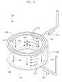
- FIG. 3illustrates a magnetically encoded ring for a roller bearing according to an embodiment of the invention.
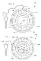
- FIG. 4is an illustration of a roller bearing having an outer magnetically encoded ring according to an embodiment of the invention.
- FIG. 5is an illustration of a roller bearing having an inner magnetically encoded ring according to an embodiment of the invention.
- FIG. 6illustrates a magnetically encoded ring for a thrust bearing according to an embodiment of the invention.
- FIG. 7is an illustration of a thrust bearing having an encoded ring according to an embodiment of the invention.
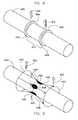
- FIG. 8illustrates a magnetically encoded shaft according to an embodiment of the invention.
- FIG. 9illustrates a magnetically encoded shaft according to an embodiment of the invention.
- a system and methodare shown for monitoring a condition of a bearing in an electrical motor.
- the inventionis equally applicable to other rotating devices that result in electrical current passing through balls of a bearing.
- the invention presented hereinneed not be limited to an electrical motor, but may include any rotating device having bearings therein that are susceptible to bearing currents passing therethrough.
- embodiments of the invention described hereininclude a ring that is magnetically encoded and coupled or otherwise attached to one or more bearing races.
- additional embodimentsas will be discussed, include races or other components that are themselves ferromagnetic materials that may be magnetically encoded, thus forgoing a separate magnetically encoded ring attached.
- bearing components of an electrical motormay be magnetically encoded and used to monitor a condition of a bearing in an electrical motor in order to predict failure of the bearing.
- bearing currentsincrease during life of the bearing, the bearing currents disturb and affect the magnetization of the magnetic encoded component(s).
- monitoring bearing currents via a magnetically encoded componentyield a condition of a bearing that may be used to proactively replace the bearing before failure of the bearing, according to embodiments of the invention.
- the historically acquired datamay be based on monitoring and failure data acquired in the field (i.e., in functioning units at customer sites, etc. . . . ), or may be based on monitoring and failure data acquired in test rigs in, for instance, test laboratories.
- a flowchart 50illustrates a broad overview of acquisition of bearing condition data according to an embodiment of the invention.
- Flowchart 50begins with fabrication of bearings at step 52 , each bearing having one or more magnetically encoded bearing components and each bearing having essentially a single direction of magnetization.
- bearing component(s)are permanently encoded, which means that the bearing component(s) retain magnetization after application of a pulsed current thereto.
- permanent magnetizationmay likewise be de-magnetized as is commonly understood within the art.
- the magnetically encoded bearing componentsmay include one or more bearing races and/or a magnetically encoded bearing shaft, as will be discussed in embodiments of the invention.
- the bearingsare assembled into electrical motors and/or test devices, and such assembly includes placement of magnetic field sensor(s) proximately to the magnetically encoded bearing component(s).
- the magnetic flux density proximate the magnetically encoded bearing component(s)is monitored and recorded during the life of the bearing.
- the bearingsmay be in devices in the “field” or may be in test rigs in laboratories, as examples. In such fashion, life data of the bearing is monitored and acquired as the bearing progresses from early life through failure.
- a pool of bearing life datais acquired as a function of bearing current, which is a function of the field disturbance that is measured proximately to the magnetically encoded bearing component(s) via the magnetic flux density.
- a historical bearing life databasemay be assembled and continually built upon that is based on field disturbance that is a function of bearing current.
- field disturbance proximate an encoded bearing componentmay be used to directly monitor a bearing condition in order to proactively predict bearing failure.
- predictionsmay be based on absolute measurements of the magnetic flux density or may be based on changes in the magnetic flux density over time, as examples.
- additional measurement informationmay be yielded by measuring in two or even all three Euclidean 3-space vectors, proximately and with respect to the originally encoded magnetic field flux lines.
- the magnetically encoded bearing componentsmay include multiple bearing types and multiple bearing configurations—of components and of measurement locations.
- a historical bearing databasemay be generated for each unique configuration, measurement location, and measurement orientation.
- a process 70includes step 72 , wherein at least one bearing component is magnetically encoded having essentially a single direction of magnetic polarization according to embodiments of the invention.
- a bearingis assembled at step 74 and installed into an electrical motor. Magnetic flux density in the bearing component is measured and monitored at step 76 and is compared to a historical database, such as one acquired as discussed with respect to FIG. 1 , at step 78 .
- the condition of the bearingis determined based on the historical database and based on the historical understanding that has been developed.
- a predictionis made of whether the bearing is going to imminently fail or fail in the near future.
- Such predictionmay be used to proactively replace a bearing within the electrical motor during, for instance, a scheduled maintenance period, or such prediction may be used to avoid a catastrophic bearing failure, as examples. Further, such monitoring may be local to the electrical device, or may be remotely monitored via a processing unit, via a computer, or via the Internet, as examples. Thus, if bearing failure is predicted imminently or in the near future 82 , then the bearing may be proactively replaced at step 84 . However, if bearing failure is not predicted 86 , then the system may continue to monitor magnetic flux density in the bearing component at step 76 .
- FIG. 3illustrates a magnetic encoding of a ring according to an embodiment of the invention.
- ring 100is a ferromagnetic material that includes an inner surface 102 and an outer surface 104 .
- Ring 100includes a first axial surface 106 and a second axial surface 108 .
- a first ring electrode 110is placed in contact with first axial surface 106
- a second ring electrode 112is placed in contact with second axial surface 108 .
- Pulsed currents 114are applied to the first ring electrode 110 , resulting in a current density vector 116 passing through ring 100 in a substantially axial direction 118 and as a return current 120 .
- ring 100may be magnetically encoded and used in, for instance, a roller bearing as illustrated in FIGS. 4 and 5 , in order to monitor a bearing condition thereof.
- ring 100may be shrink fitted or otherwise attached to a bearing race in a path to ground that may be used to monitor a condition of a bearing.
- roller bearing 200that may be used in an electrical motor (not shown) according to embodiments of the invention.
- Roller bearing 200includes an inner race 202 and an outer race 204 and a plurality of bearing balls 206 positioned therebetween.
- Roller bearing assembly 200includes a magnetically encoded ring 208 that is in a path to ground and is encoded in the fashion as illustrated in FIG. 3 above.
- Each ballcontacts the races 202 , 204 at respective contact points 210 , 212 .
- bearing currentspass through the bearing balls.
- the bearing currentsdisturb the magnetization in magnetically encoded ring 208 , and the disturbance may be detected via a magnetic field sensor 214 positioned proximately thereto. Referring to FIG.
- magnetic field sensor 214is illustrated as being positioned external to and tangential or perpendicular to an outer circumference 217 of roller bearing assembly 200 to detect disturbances in magnetic field lines, such as parallel magnetization lines 122 . Accordingly, magnetic field sensor 214 is positioned to detect disturbances in magnetization 122 in a direction that is tangential or perpendicular to outer circumference 217 .
- additional magnetic field sensorssimilar to magnetic field sensor 214 , may likewise be used to detect and measure disturbances therein by orienting the additional magnetic field sensors perpendicular to the orientation of the first sensor
- the disturbancesmay be compared to historically obtained data and may be used to monitor a condition of roller bearing assembly 200 .
- magnetic field sensor 214is connected to a signal conditioning and processing unit 215 , which may be accessed via for instance a computer, and which may further be accessed remotely for monitoring a condition of roller bearing assembly 200 .
- a signal conditioning and processing unit 215may be accessed via for instance a computer, and which may further be accessed remotely for monitoring a condition of roller bearing assembly 200 .
- the bearing currentslikewise increase, and such increase may be measured through magnetic field disturbances proximate to a magnetized surface different than the magnetic field caused by the magnetized surface of a normally operating bearing.
- FIG. 5illustrates a roller bearing 240 that may be used in an electrical motor for monitoring condition of bearing 240 , according to another embodiment of the invention.
- Roller bearing assembly 240includes an inner race 242 and an outer race 244 and a plurality of balls 246 positioned therebetween.
- Roller bearing assembly 240includes a magnetically encoded ring 248 having an inner circumference 251 that is in a path to ground and is encoded in the fashion as illustrated in FIG. 3 above.
- Each ballcontacts the races 242 , 244 at respective contact points 250 , 252 .
- bearing currentspass through the bearing balls.
- Such bearing currentsdisturb the magnetization in magnetically encoded ring 248 , and the disturbance may be detected via a magnetic field sensor 254 positioned proximately thereto.
- magnetic field sensor 254is positioned to detect magnetic field disturbances similar to that described with respect to FIG. 4 and in a direction that is tangential or perpendicular to inner circumference 251 .
- additional magnetic field sensorssimilar to magnetic field sensor 254 , may likewise be used to detect and measure disturbances therein by orienting the additional magnetic field sensors perpendicular to the orientation of the first sensor.
- the disturbancesmay be compared to historically obtained data and may be used to monitor a condition of roller bearing assembly 240 .
- the bearing currentslikewise increase, and such increase may be measured through magnetic field disturbances proximate to a magnetized surface different than the magnetic field caused by the magnetized surface of a normally operating bearing.
- FIGS. 4 and 5each are illustrated having a single magnetically encoded ring therein.
- a roller bearingmay have both an outer ring such as magnetically encoded ring 208 of FIG. 4 and an inner ring such as magnetically encoded ring 248 of FIG. 5 . Accordingly, bearing condition data may be obtained in both locations and in multiple orientations at each location, thus providing additional information for monitoring a condition of a roller bearing.
- magnetically encoded ring 208 of FIG. 4 and magnetically encoded ring 248 of FIG. 5are illustrated as rings that are separate from their respective races 204 , 242 to which they are coupled, embodiments of the invention include magnetization of the races themselves in lieu of providing additional rings 208 , 248 .
- the race(s)may be made of a ferromagnetic material that can be magnetically encoded and in a path to ground to enable monitoring of a bearing condition via a magnetic field sensor as discussed above.
- the races themselvesmay be magnetically encoded in the fashion described with respect to FIG. 3 .
- an inner race, an outer race, or both races of a roller bearing assemblymay be magnetized and monitored via a signal conditioning and processing unit 249 to provide an indication of bearing currents and a condition of the bearing.
- FIGS. 6 and 7illustrate a thrust bearing according to embodiments of the invention.
- a ringmay be magnetically encoded in an analogous fashion to the ring encoded as discussed with respect to FIG. 3 .
- the ringis encoded to have a magnetic polarization that is oriented at an angle of 90° with respect to that illustrated in FIG. 3 .
- a ferromagnetic ring 300 for use in a thrust bearingincludes a first axial surface 302 and a second axial surface 304 , as well as an inner surface 306 and an outer surface 308 .
- a first ring electrode 310is placed in contact with outer surface 308
- a second ring electrode 312is placed in contact with inner surface 306 of ring 300 .
- Pulsed currents 314are applied to first ring electrode 310 , resulting in a current density vector 316 passing through ring 300 in a substantially radial direction and as a return current 318 .
- ring 300may be encoded and used in, for instance, a thrust bearing as illustrated in FIG. 7 in order to monitor a bearing condition thereof. As with the embodiments illustrated in FIGS. 4 and 5 , such monitoring may be in one, two, or all three orientations with respect to the lines of magnetization 320 .
- ring 300may be mechanically attached to a bearing race in a path to ground that may be used to monitor a condition of a bearing.
- Thrust bearing 350may be used in an electrical motor (not shown) according to embodiments of the invention.
- Thrust bearing 350includes a first thrust bearing race 352 and a second thrust bearing race 354 and a plurality of bearing balls 356 positioned therebetween.
- Thrust bearing 350includes one or more magnetically encoded rings 358 that are in a path to ground and are each encoded in the fashion as discussed above with respect to FIG. 6 .
- Each ball 356contacts the thrust bearing races 352 , 354 at respective contact points (not shown). Thus, during operation bearing currents pass through bearing balls 356 .
- Such bearing currentsdisturb the magnetic field in the one or more magnetically encoded rings 358 , and the disturbance may be detected via respective magnetic field sensors 360 positioned proximate thereto and monitored via a signal conditioning and processing unit 361 .
- the disturbancesmay be compared to historically obtained data and may be used to monitor a condition of thrust bearing 350 .
- the bearing currentslikewise increase, and such increase may be measured through magnetic field disturbances proximate to a magnetized surface different than the magnetic field caused by the magnetized surface of a normally operating bearing.
- thrust bearing 350may be fabricated having rings 352 , 354 that are themselves fabricated (one or both) of a ferromagnetic material and encoded in lieu of using separate rings 358 .
- rings 352 , 354are encoded, and the bearing currents are monitored therein using magnetic field sensors 360 as discussed above.
- a ferromagnetic shaft for an electrical motormay be magnetically encoded instead of the bearings themselves, and the shaft field disturbance may be monitored to monitor a bearing condition.
- a shaft 400includes two Shaft Processing Holding Clamps (SPHCs) 402 , 404 that are placed at respective borders 406 , 408 of a planned sensing encoding region 410 over which a bearing, such as a roller bearing (not shown), may be placed.
- SPHCsShaft Processing Holding Clamps
- a pulsed electrical currentmay enter 412 the shaft at SPHC 404 and may exit 414 the shaft at SPHC 402 .
- Region 410will thus become a uniformly encoded region having a essentially a single direction of magnetic polarization that may be used for bearing current monitoring according to this embodiment.
- a depth of magnetization in shaft 400may be controlled by controlling a frequency and duration of the applied pulses.
- a shaft 440may be magnetically encoded in sections according to another embodiment of the invention. If electrodes are installed at sufficient distance from the bearing, then the bearing section can be magnetically encoded with sufficient uniformity and having essentially a single direction of magnetic polarization. Thus, when a spacing between individual circumferentially placed current entry points are relatively large in relation to a diameter of the shaft (and equally large are the spacings between the circumferentially placed current exit points), then a poor rotational signal uniformity results. In such a case, the length of the pulsed current encoded segment has to be as large as possible, otherwise the created magnetic field may be circumferentially non-uniform. According to this embodiment, if a pulsed current encoded segment is long enough, then a uniform current distribution is achieved that generates the essentially single direction of magnetic polarization.
- shaft 440includes a first electrode 442 and a second electrode 444 and electrical input contact points 446 that are electrically connected to first electrode 442 .
- electrical output contact points 448are electrically connected to second electrode 444 .
- a pulsed current 450is applied to first electrode 442 , the pulsed current is caused to pass to shaft 440 through electrical contact points 446 and to exit through electrical output contact points 448 and to second electrode 444 .
- a plurality of magnetically encoded regions 452each having a substantially uniform magnetic flux therein and each having a single and uniform polarization, may be generated in shaft 440 .
- a bearing conditionmay be monitored therewith by monitoring disturbances in the magnetic flux density proximate thereto.
- a shaftmay be magnetically encoded according to embodiments of the invention, as shown in exemplary illustrations in FIGS. 8 and 9 .
- bearing currentsmay be monitored therein as discussed herein, and the condition of a bearing positioned about the encoded shaft may likewise be inferred based on historically obtained data.
- the life of the bearingmay be, likewise, monitored and the bearing proactively replaced during operation of an electrical machine in which it is placed.
- magnetic field sensorsare illustrated as positioned proximate the encoded component (e.g., encoded ring 208 of FIG. 4 ). In embodiments of the invention it is desirable to position the sensor(s) between 0 and 10 mm, preferably not more than 5 mm distant therefrom. Further, in the embodiments illustrated, mapping of the magnetic fields may be conducted while the system with components is being assembled. In embodiments of the invention, the magnetic field sensors may be passive components that may be embedded within components. As an example, FIG. 5 illustrates magnetic field sensor 254 positioned internal to inner circumference 251 . However, such an embodiment may include a shaft (not shown) positioned therein and in contact with inner circumference 251 .
- magnetic field sensor 254may be embedded within the shaft and periodically monitored for detection of bearing currents.
- magnetic sensingmay be done while a rotor-shaft system is partially or fully disassembled.
- the systemmay be partially or fully disassembled and the sensor, such as magnetic field sensor 254 , may be connected to processing unit 249 to ascertain a condition of the bearing.
- a plug for wiringmay be provided that is used for periods of ascertaining a condition of a bearing.
- the bearingmay be operated during normal operation and without continuous monitoring of a bearing condition. Then, during periods of condition monitoring, the system may be disassembled and the plug attached to a processing unit in order to measure and determine a condition thereof
- each electrode 110 , 112is illustrating as covering an entire 360° circumference of ring 100 , it is possible to magnetically encode only a portion of the circumference of ring 100 , so long as the electrodes encompass substantially the same area of ring 100 and are substantially opposite to one another.
- the amount or portion of the circumferencemay be selected based on the magnitude of the relevant bearing currents. Thus, if there are relevant bearing currents of sufficient magnitude, they will occur in the limited circumferential portion of the ring itself.
- a sectional encodingincludes less technical effort than for a full encoding, simplifying the fabrication costs by reducing the necessary encoding current, as an example.
- a sectional encodingcan be applied at lower cost and can be used in the same fashion to detect bearing currents through magnetic inspection.
- a technical contribution for the disclosed method and apparatusis that it provides for a computer implemented system and method of monitoring a condition of a bearing.
- an electrical motor bearing condition monitoring systemincludes an assembly that includes a shaft, a first bearing race coupled to the shaft, a plurality of bearing balls, and a second bearing race coupled to the first bearing race via the plurality of bearing balls. A portion of the assembly has a magnetic field encoded thereon.
- the monitoring systemincludes a magnetic field sensor positioned proximately to the magnetized assembly and configured to measure the magnetic field, and a processing unit configured to detect changes in the magnetic field via the magnetic field sensor that occur due to passage of electrical current through the bearing balls.
- a methodincludes providing components of a bearing assembly, the components comprising at least one of a first bearing race, a second bearing race, and a bearing shaft, magnetically encoding at least a portion of one of the components, assembling the components of the bearing assembly together, and configuring a controller to monitor a magnetic field for disturbances in the magnetization that result from bearing currents proximate to the magnetically encoded portion during operation of the bearing assembly, and predict a failure of the bearing assembly based on the monitored magnetic field.
- Another embodiment of the inventionincludes an apparatus that includes a shaft, a first bearing race coupled to the shaft, a second bearing race coupled to the shaft, and a plurality of bearing balls positioned between the first bearing race and the second bearing race.
- One of the shaft, a portion of the first bearing race, and a portion of the second bearing raceis magnetically encoded having essentially a single direction of magnetic polarization.
Landscapes
- Engineering & Computer Science (AREA)
- General Engineering & Computer Science (AREA)
- Mechanical Engineering (AREA)
- Microelectronics & Electronic Packaging (AREA)
- Power Engineering (AREA)
- Physics & Mathematics (AREA)
- General Physics & Mathematics (AREA)
- Rolling Contact Bearings (AREA)
- Testing Of Devices, Machine Parts, Or Other Structures Thereof (AREA)
- Manufacture Of Motors, Generators (AREA)
Abstract
Description
Claims (25)
Priority Applications (4)
| Application Number | Priority Date | Filing Date | Title |
|---|---|---|---|
| US12/542,046US8229682B2 (en) | 2009-08-17 | 2009-08-17 | Apparatus and method for bearing condition monitoring |
| EP10171542.3AEP2288000A3 (en) | 2009-08-17 | 2010-08-02 | Apparatus and method for bearing condition monitoring |
| JP2010181183AJP5693083B2 (en) | 2009-08-17 | 2010-08-13 | Bearing state monitoring apparatus and method |
| CN201010262686.3ACN101995433B (en) | 2009-08-17 | 2010-08-17 | Apparatus and method for bearing condition monitoring |
Applications Claiming Priority (1)
| Application Number | Priority Date | Filing Date | Title |
|---|---|---|---|
| US12/542,046US8229682B2 (en) | 2009-08-17 | 2009-08-17 | Apparatus and method for bearing condition monitoring |
Publications (2)
| Publication Number | Publication Date |
|---|---|
| US20110040495A1 US20110040495A1 (en) | 2011-02-17 |
| US8229682B2true US8229682B2 (en) | 2012-07-24 |
Family
ID=43244950
Family Applications (1)
| Application Number | Title | Priority Date | Filing Date |
|---|---|---|---|
| US12/542,046Active2030-11-06US8229682B2 (en) | 2009-08-17 | 2009-08-17 | Apparatus and method for bearing condition monitoring |
Country Status (4)
| Country | Link |
|---|---|
| US (1) | US8229682B2 (en) |
| EP (1) | EP2288000A3 (en) |
| JP (1) | JP5693083B2 (en) |
| CN (1) | CN101995433B (en) |
Cited By (11)
| Publication number | Priority date | Publication date | Assignee | Title |
|---|---|---|---|---|
| WO2013077795A1 (en)* | 2011-11-23 | 2013-05-30 | Aktiebolaget Skf | Method and system for detection of electric currents through a bearing of a rotating system |
| US10403116B2 (en) | 2017-06-20 | 2019-09-03 | General Electric Company | Electrical signature analysis of electrical rotating machines |
| US10416001B2 (en)* | 2017-08-25 | 2019-09-17 | Infineon Technologies Ag | Magnet arrangement for rotational angle detection |
| US10928814B2 (en) | 2017-02-24 | 2021-02-23 | General Electric Technology Gmbh | Autonomous procedure for monitoring and diagnostics of machine based on electrical signature analysis |
| US11169511B2 (en) | 2016-05-09 | 2021-11-09 | Strong Force Iot Portfolio 2016, Llc | Methods and systems for network-sensitive data collection and intelligent process adjustment in an industrial environment |
| US11175653B2 (en) | 2017-08-02 | 2021-11-16 | Strong Force Iot Portfolio 2016, Llc | Systems for data collection and storage including network evaluation and data storage profiles |
| US11221613B2 (en) | 2016-05-09 | 2022-01-11 | Strong Force Iot Portfolio 2016, Llc | Methods and systems for noise detection and removal in a motor |
| US11735982B2 (en) | 2021-03-18 | 2023-08-22 | General Electric Company | Bearing current mitigation for an electric machine embedded in a gas turbine engine |
| US20230304478A1 (en)* | 2020-10-09 | 2023-09-28 | PROKON Regenerative Energien eG | Method for monitoring one or more electric drives of an electromechanical system |
| US11774944B2 (en) | 2016-05-09 | 2023-10-03 | Strong Force Iot Portfolio 2016, Llc | Methods and systems for the industrial internet of things |
| US12140930B2 (en) | 2016-05-09 | 2024-11-12 | Strong Force Iot Portfolio 2016, Llc | Method for determining service event of machine from sensor data |
Families Citing this family (22)
| Publication number | Priority date | Publication date | Assignee | Title |
|---|---|---|---|---|
| US8229682B2 (en)* | 2009-08-17 | 2012-07-24 | General Electric Company | Apparatus and method for bearing condition monitoring |
| DE102010002294A1 (en)* | 2010-02-24 | 2011-08-25 | Siemens Aktiengesellschaft, 80333 | System or method for determining a storage condition |
| CN104067011B (en) | 2011-11-23 | 2017-07-28 | Skf公司 | Rotary system state monitoring device and method, computer readable medium and management server |
| US8760309B2 (en)* | 2011-12-05 | 2014-06-24 | GM Global Technology Operations LLC | Fuel cell compressor air bearing wear sensor |
| CN104220870A (en)* | 2012-04-12 | 2014-12-17 | 西门子公司 | Sensor element with acoustic emission sensor |
| CN103063419A (en)* | 2012-10-30 | 2013-04-24 | 西安交通大学 | Quality testing device for motorized spindle rotor |
| CN105518429A (en)* | 2013-09-13 | 2016-04-20 | 斯凯孚公司 | Device, method and computer program product |
| CN105890563A (en)* | 2014-10-24 | 2016-08-24 | 南通山口精工机电有限公司 | Adjustable difference amplitude meter for measuring miniature bearing |
| WO2016157347A1 (en)* | 2015-03-30 | 2016-10-06 | 株式会社日立製作所 | Bearing current monitoring device and rotary electric machine |
| CN105372070B (en)* | 2015-12-15 | 2018-06-01 | 新昌县羽林街道全顺机械厂 | A kind of bearing installation accuracy detection device |
| EP3309529B1 (en)* | 2016-10-11 | 2022-02-23 | ABB Schweiz AG | Prediction of remaining useful lifetime for bearings |
| EP3330493B1 (en)* | 2016-12-02 | 2019-05-01 | Rolls-Royce Deutschland Ltd & Co KG | Control system and method for a gas turbine engine |
| CN108918651A (en)* | 2018-04-16 | 2018-11-30 | 东南大学 | Bearing inner ring rolling contact fatigue non-destructive testing device and manufacturing method |
| EP3588049A1 (en)* | 2018-06-27 | 2020-01-01 | ABB Schweiz AG | Decision of faulty bearing |
| DE102018115847A1 (en)* | 2018-06-29 | 2020-01-02 | Sensitec Gmbh | Wear monitoring device and ball screw drive |
| CN109226352B (en)* | 2018-09-12 | 2020-02-07 | 马鞍山钢铁股份有限公司 | Method for monitoring bearing degradation state of transmission speed reducer of multi-roller driven straightener |
| EP3623828A1 (en)* | 2018-09-14 | 2020-03-18 | Hitech & Development Wireless Sweden AB | Machine operation monitoring |
| EP3660482A1 (en)* | 2018-11-30 | 2020-06-03 | Siemens Aktiengesellschaft | System, apparatus and method of determining remaining life of a bearing |
| WO2020255476A1 (en)* | 2019-06-17 | 2020-12-24 | 日本精工株式会社 | Rolling machine element fatigue diagnosis method and rolling machine element fatigue diagnosis system |
| CN110645266B (en)* | 2019-06-26 | 2020-11-27 | 扬州市舜意机械有限公司 | Sensing integrated joint bearing and use method thereof |
| JP7686178B1 (en)* | 2024-07-10 | 2025-05-30 | 三菱電機株式会社 | Bearing condition detection device, rotating electrical machine, and bearing condition detection method |
| CN120595204B (en)* | 2025-08-07 | 2025-10-03 | 太原工业学院 | Bearing fault diagnosis method and system |
Citations (17)
| Publication number | Priority date | Publication date | Assignee | Title |
|---|---|---|---|---|
| US2439035A (en)* | 1945-03-08 | 1948-04-06 | Gen Motors Corp | Bearing testing machine |
| US2468509A (en)* | 1945-11-15 | 1949-04-26 | Ingersoll Rand Co | Bearing wear indicating and adjusting device for pistons |
| US2538790A (en)* | 1946-06-18 | 1951-01-23 | William E Merrill | Electric bearing tester |
| US2883255A (en)* | 1954-04-28 | 1959-04-21 | Panellit Inc | Automatic process logging system |
| US3108264A (en)* | 1957-07-08 | 1963-10-22 | Heinoo Lauri | Bearing wear sensor |
| US3155956A (en)* | 1963-02-15 | 1964-11-03 | Beloit Corp | Bearing failure predicting device |
| US3183500A (en)* | 1963-02-15 | 1965-05-11 | Beloit Corp | Bearing failure predicting device |
| US3201996A (en)* | 1961-11-29 | 1965-08-24 | Bosch Arma Corp | Bearing testing apparatus |
| US3373300A (en)* | 1966-02-04 | 1968-03-12 | Francis P. Sullivan | Electric bearing failure indicator |
| US3508241A (en)* | 1967-09-06 | 1970-04-21 | Bendix Corp | Bearing failure sensing device |
| US5336996A (en)* | 1992-08-21 | 1994-08-09 | The Duriron Company, Inc. | Hall effect monitoring of wear of bearing supporting a rotor within a stationary housing |
| US6043643A (en)* | 1996-10-23 | 2000-03-28 | Skf France | Sensor for a rotating member of a bearing having reinforcing elements |
| US6100809A (en)* | 1998-11-24 | 2000-08-08 | Alliedsignal Inc. | Bearing wear detection system |
| US7243557B2 (en) | 2003-12-30 | 2007-07-17 | Nctengineering Gmbh | Torque sensor |
| US20090093975A1 (en)* | 2006-05-01 | 2009-04-09 | Dynamic Measurement Consultants, Llc | Rotating bearing analysis and monitoring system |
| US20100172605A1 (en)* | 2007-02-14 | 2010-07-08 | Schaeffler Kg | Rolling bearing device comprising an integrated sensor system |
| JP2011039056A (en)* | 2009-08-17 | 2011-02-24 | General Electric Co <Ge> | Bearing state monitoring device and method |
Family Cites Families (13)
| Publication number | Priority date | Publication date | Assignee | Title |
|---|---|---|---|---|
| US4875785A (en)* | 1987-11-13 | 1989-10-24 | The Torrington Company | Thrust bearing with a magnetic field detector |
| AU605882B2 (en)* | 1987-11-13 | 1991-01-24 | Torrington Company, The | Bearing with a magnetic field detector |
| US4914387A (en)* | 1988-04-04 | 1990-04-03 | The Torrington Company | Magnetic speed sensor with an adaptive threshold circuit for use with a bearing assembly |
| CN2096759U (en)* | 1991-06-10 | 1992-02-19 | 哈尔滨铁路局哈尔滨科学技术研究所 | Magnetizing apparatus for wheel flaw detection |
| DE10135784B4 (en)* | 2000-07-26 | 2015-09-17 | Ntn Corp. | Bearing provided with a rotation sensor and motor equipped therewith |
| JP4250890B2 (en)* | 2001-11-22 | 2009-04-08 | 日本精工株式会社 | Rolling bearing with sensor |
| CN100394188C (en)* | 2003-11-28 | 2008-06-11 | Ntn株式会社 | Bearing with rotation sensor and electric motor using the same |
| JP4800221B2 (en)* | 2003-12-30 | 2011-10-26 | エヌシーティーエンジニアリング ゲーエムベーハー | Torque sensor |
| WO2006030786A1 (en)* | 2004-09-13 | 2006-03-23 | Nsk Ltd. | Abnormality diagnosis device and abnormality diagnosis method |
| EP1859458B1 (en)* | 2005-03-16 | 2012-02-15 | NCTEngineering GmbH | A method and an array for magnetizing a magnetizable object |
| JP2007064778A (en)* | 2005-08-31 | 2007-03-15 | Ntn Corp | Bearing for wheel with sensor |
| JP4003088B2 (en)* | 2006-12-20 | 2007-11-07 | 日本精工株式会社 | Rotating body abnormality diagnosis method and apparatus |
| JP4957412B2 (en)* | 2007-07-02 | 2012-06-20 | 日本精工株式会社 | Inspection method for state quantity measuring device of rolling bearing unit |
- 2009
- 2009-08-17USUS12/542,046patent/US8229682B2/enactiveActive
- 2010
- 2010-08-02EPEP10171542.3Apatent/EP2288000A3/ennot_activeWithdrawn
- 2010-08-13JPJP2010181183Apatent/JP5693083B2/enactiveActive
- 2010-08-17CNCN201010262686.3Apatent/CN101995433B/enactiveActive
Patent Citations (18)
| Publication number | Priority date | Publication date | Assignee | Title |
|---|---|---|---|---|
| US2439035A (en)* | 1945-03-08 | 1948-04-06 | Gen Motors Corp | Bearing testing machine |
| US2468509A (en)* | 1945-11-15 | 1949-04-26 | Ingersoll Rand Co | Bearing wear indicating and adjusting device for pistons |
| US2538790A (en)* | 1946-06-18 | 1951-01-23 | William E Merrill | Electric bearing tester |
| US2883255A (en)* | 1954-04-28 | 1959-04-21 | Panellit Inc | Automatic process logging system |
| US3108264A (en)* | 1957-07-08 | 1963-10-22 | Heinoo Lauri | Bearing wear sensor |
| US3201996A (en)* | 1961-11-29 | 1965-08-24 | Bosch Arma Corp | Bearing testing apparatus |
| US3155956A (en)* | 1963-02-15 | 1964-11-03 | Beloit Corp | Bearing failure predicting device |
| US3183500A (en)* | 1963-02-15 | 1965-05-11 | Beloit Corp | Bearing failure predicting device |
| US3373300A (en)* | 1966-02-04 | 1968-03-12 | Francis P. Sullivan | Electric bearing failure indicator |
| US3508241A (en)* | 1967-09-06 | 1970-04-21 | Bendix Corp | Bearing failure sensing device |
| US5336996A (en)* | 1992-08-21 | 1994-08-09 | The Duriron Company, Inc. | Hall effect monitoring of wear of bearing supporting a rotor within a stationary housing |
| US6043643A (en)* | 1996-10-23 | 2000-03-28 | Skf France | Sensor for a rotating member of a bearing having reinforcing elements |
| US6100809A (en)* | 1998-11-24 | 2000-08-08 | Alliedsignal Inc. | Bearing wear detection system |
| US7243557B2 (en) | 2003-12-30 | 2007-07-17 | Nctengineering Gmbh | Torque sensor |
| US20090093975A1 (en)* | 2006-05-01 | 2009-04-09 | Dynamic Measurement Consultants, Llc | Rotating bearing analysis and monitoring system |
| US7606673B2 (en)* | 2006-05-01 | 2009-10-20 | Dynamic Measurement Consultants, Llc | Rotating bearing analysis and monitoring system |
| US20100172605A1 (en)* | 2007-02-14 | 2010-07-08 | Schaeffler Kg | Rolling bearing device comprising an integrated sensor system |
| JP2011039056A (en)* | 2009-08-17 | 2011-02-24 | General Electric Co <Ge> | Bearing state monitoring device and method |
Non-Patent Citations (3)
| Title |
|---|
| "Bearing Currents in Modern AC Drive Systems," Technical Guide No. 5, ABB Automation Group Ltd., 1999. |
| "Inverter-Driven Induction Motors Shaft and Bearing Current Solutions," Baldor Electric Company. |
| Erdman et al., "Effect of PWM Inverters on AC Motor Bearing Currents and Shaft Voltages", IEEE Transactions on Industry Applications, vol. 32, No. 2, Mar./Apr. 1996, pp. 250-259. |
Cited By (76)
| Publication number | Priority date | Publication date | Assignee | Title |
|---|---|---|---|---|
| WO2013077795A1 (en)* | 2011-11-23 | 2013-05-30 | Aktiebolaget Skf | Method and system for detection of electric currents through a bearing of a rotating system |
| US9551733B2 (en) | 2011-11-23 | 2017-01-24 | Aktiebolaget Skf | Method and apparatus for detecting a current in a rotating system |
| US11409266B2 (en) | 2016-05-09 | 2022-08-09 | Strong Force Iot Portfolio 2016, Llc | System, method, and apparatus for changing a sensed parameter group for a motor |
| US11646808B2 (en) | 2016-05-09 | 2023-05-09 | Strong Force Iot Portfolio 2016, Llc | Methods and systems for adaption of data storage and communication in an internet of things downstream oil and gas environment |
| US11194318B2 (en) | 2016-05-09 | 2021-12-07 | Strong Force Iot Portfolio 2016, Llc | Systems and methods utilizing noise analysis to determine conveyor performance |
| US11221613B2 (en) | 2016-05-09 | 2022-01-11 | Strong Force Iot Portfolio 2016, Llc | Methods and systems for noise detection and removal in a motor |
| US11243528B2 (en) | 2016-05-09 | 2022-02-08 | Strong Force Iot Portfolio 2016, Llc | Systems and methods for data collection utilizing adaptive scheduling of a multiplexer |
| US11243521B2 (en) | 2016-05-09 | 2022-02-08 | Strong Force Iot Portfolio 2016, Llc | Methods and systems for data collection in an industrial environment with haptic feedback and data communication and bandwidth control |
| US11243522B2 (en) | 2016-05-09 | 2022-02-08 | Strong Force Iot Portfolio 2016, Llc | Methods and systems for detection in an industrial Internet of Things data collection environment with intelligent data collection and equipment package adjustment for a production line |
| US11256243B2 (en) | 2016-05-09 | 2022-02-22 | Strong Force loT Portfolio 2016, LLC | Methods and systems for detection in an industrial Internet of Things data collection environment with intelligent data collection and equipment package adjustment for fluid conveyance equipment |
| US11256242B2 (en) | 2016-05-09 | 2022-02-22 | Strong Force Iot Portfolio 2016, Llc | Methods and systems of chemical or pharmaceutical production line with self organizing data collectors and neural networks |
| US11262737B2 (en) | 2016-05-09 | 2022-03-01 | Strong Force Iot Portfolio 2016, Llc | Systems and methods for monitoring a vehicle steering system |
| US11169511B2 (en) | 2016-05-09 | 2021-11-09 | Strong Force Iot Portfolio 2016, Llc | Methods and systems for network-sensitive data collection and intelligent process adjustment in an industrial environment |
| US11307565B2 (en) | 2016-05-09 | 2022-04-19 | Strong Force Iot Portfolio 2016, Llc | Method and system of a noise pattern data marketplace for motors |
| US11327475B2 (en) | 2016-05-09 | 2022-05-10 | Strong Force Iot Portfolio 2016, Llc | Methods and systems for intelligent collection and analysis of vehicle data |
| US11340589B2 (en) | 2016-05-09 | 2022-05-24 | Strong Force Iot Portfolio 2016, Llc | Methods and systems for detection in an industrial Internet of Things data collection environment with expert systems diagnostics and process adjustments for vibrating components |
| US11347205B2 (en) | 2016-05-09 | 2022-05-31 | Strong Force Iot Portfolio 2016, Llc | Methods and systems for network-sensitive data collection and process assessment in an industrial environment |
| US11347206B2 (en) | 2016-05-09 | 2022-05-31 | Strong Force Iot Portfolio 2016, Llc | Methods and systems for data collection in a chemical or pharmaceutical production process with haptic feedback and control of data communication |
| US11347215B2 (en) | 2016-05-09 | 2022-05-31 | Strong Force Iot Portfolio 2016, Llc | Methods and systems for detection in an industrial internet of things data collection environment with intelligent management of data selection in high data volume data streams |
| US11353850B2 (en) | 2016-05-09 | 2022-06-07 | Strong Force Iot Portfolio 2016, Llc | Systems and methods for data collection and signal evaluation to determine sensor status |
| US11353851B2 (en) | 2016-05-09 | 2022-06-07 | Strong Force Iot Portfolio 2016, Llc | Systems and methods of data collection monitoring utilizing a peak detection circuit |
| US11360459B2 (en) | 2016-05-09 | 2022-06-14 | Strong Force Iot Portfolio 2016, Llc | Method and system for adjusting an operating parameter in a marginal network |
| US11366455B2 (en) | 2016-05-09 | 2022-06-21 | Strong Force Iot Portfolio 2016, Llc | Methods and systems for optimization of data collection and storage using 3rd party data from a data marketplace in an industrial internet of things environment |
| US11366456B2 (en) | 2016-05-09 | 2022-06-21 | Strong Force Iot Portfolio 2016, Llc | Methods and systems for detection in an industrial internet of things data collection environment with intelligent data management for industrial processes including analog sensors |
| US11372394B2 (en) | 2016-05-09 | 2022-06-28 | Strong Force Iot Portfolio 2016, Llc | Methods and systems for detection in an industrial internet of things data collection environment with self-organizing expert system detection for complex industrial, chemical process |
| US11372395B2 (en) | 2016-05-09 | 2022-06-28 | Strong Force Iot Portfolio 2016, Llc | Methods and systems for detection in an industrial Internet of Things data collection environment with expert systems diagnostics for vibrating components |
| US11378938B2 (en) | 2016-05-09 | 2022-07-05 | Strong Force Iot Portfolio 2016, Llc | System, method, and apparatus for changing a sensed parameter group for a pump or fan |
| US11385623B2 (en) | 2016-05-09 | 2022-07-12 | Strong Force Iot Portfolio 2016, Llc | Systems and methods of data collection and analysis of data from a plurality of monitoring devices |
| US11385622B2 (en) | 2016-05-09 | 2022-07-12 | Strong Force Iot Portfolio 2016, Llc | Systems and methods for characterizing an industrial system |
| US11392111B2 (en) | 2016-05-09 | 2022-07-19 | Strong Force Iot Portfolio 2016, Llc | Methods and systems for intelligent data collection for a production line |
| US11392109B2 (en) | 2016-05-09 | 2022-07-19 | Strong Force Iot Portfolio 2016, Llc | Methods and systems for data collection in an industrial refining environment with haptic feedback and data storage control |
| US12372946B2 (en) | 2016-05-09 | 2025-07-29 | Strong Force Iot Portfolio 2016, Llc | Systems and methods for enabling user acceptance of a smart band data collection template for data collection in an industrial environment |
| US12333403B2 (en) | 2016-05-09 | 2025-06-17 | Strong Force IoT Portfolio2016, LLC | Systems for self-organizing data collection in an industrial environment |
| US12333401B2 (en) | 2016-05-09 | 2025-06-17 | Strong Force Iot Portfolio 2016, Llc | Systems for self-organizing data collection and storage in a power generation environment |
| US12333402B2 (en) | 2016-05-09 | 2025-06-17 | Strong Force Iot Portfolio 2016, Llc | Systems for self-organizing data collection and storage in a manufacturing environment |
| US11397422B2 (en) | 2016-05-09 | 2022-07-26 | Strong Force Iot Portfolio 2016, Llc | System, method, and apparatus for changing a sensed parameter group for a mixer or agitator |
| US12327168B2 (en) | 2016-05-09 | 2025-06-10 | Strong Force Iot Portfolio 2016, Llc | Systems for self-organizing data collection and storage in a refining environment |
| US11402826B2 (en) | 2016-05-09 | 2022-08-02 | Strong Force Iot Portfolio 2016, Llc | Methods and systems of industrial production line with self organizing data collectors and neural networks |
| US11281202B2 (en)* | 2016-05-09 | 2022-03-22 | Strong Force Iot Portfolio 2016, Llc | Method and system of modifying a data collection trajectory for bearings |
| US11181893B2 (en) | 2016-05-09 | 2021-11-23 | Strong Force Iot Portfolio 2016, Llc | Systems and methods for data communication over a plurality of data paths |
| US11397421B2 (en)* | 2016-05-09 | 2022-07-26 | Strong Force Iot Portfolio 2016, Llc | Systems, devices and methods for bearing analysis in an industrial environment |
| US11493903B2 (en) | 2016-05-09 | 2022-11-08 | Strong Force Iot Portfolio 2016, Llc | Methods and systems for a data marketplace in a conveyor environment |
| US11507075B2 (en) | 2016-05-09 | 2022-11-22 | Strong Force Iot Portfolio 2016, Llc | Method and system of a noise pattern data marketplace for a power station |
| US11573558B2 (en) | 2016-05-09 | 2023-02-07 | Strong Force Iot Portfolio 2016, Llc | Methods and systems for sensor fusion in a production line environment |
| US11586188B2 (en) | 2016-05-09 | 2023-02-21 | Strong Force Iot Portfolio 2016, Llc | Methods and systems for a data marketplace for high volume industrial processes |
| US11586181B2 (en) | 2016-05-09 | 2023-02-21 | Strong Force Iot Portfolio 2016, Llc | Systems and methods for adjusting process parameters in a production environment |
| US11609553B2 (en) | 2016-05-09 | 2023-03-21 | Strong Force Iot Portfolio 2016, Llc | Systems and methods for data collection and frequency evaluation for pumps and fans |
| US11609552B2 (en) | 2016-05-09 | 2023-03-21 | Strong Force Iot Portfolio 2016, Llc | Method and system for adjusting an operating parameter on a production line |
| US11415978B2 (en) | 2016-05-09 | 2022-08-16 | Strong Force Iot Portfolio 2016, Llc | Systems and methods for enabling user selection of components for data collection in an industrial environment |
| US11663442B2 (en) | 2016-05-09 | 2023-05-30 | Strong Force Iot Portfolio 2016, Llc | Methods and systems for detection in an industrial Internet of Things data collection environment with intelligent data management for industrial processes including sensors |
| US11728910B2 (en) | 2016-05-09 | 2023-08-15 | Strong Force Iot Portfolio 2016, Llc | Methods and systems for detection in an industrial internet of things data collection environment with expert systems to predict failures and system state for slow rotating components |
| US12282837B2 (en) | 2016-05-09 | 2025-04-22 | Strong Force Iot Portfolio 2016, Llc | Systems and methods for processing data collected in an industrial environment using neural networks |
| US12259711B2 (en) | 2016-05-09 | 2025-03-25 | Strong Force Iot Portfolio 2016, Llc | Methods and systems for the industrial internet of things |
| US11770196B2 (en) | 2016-05-09 | 2023-09-26 | Strong Force TX Portfolio 2018, LLC | Systems and methods for removing background noise in an industrial pump environment |
| US12244359B2 (en) | 2016-05-09 | 2025-03-04 | Strong Force Iot Portfolio 2016, Llc | Systems and methods for monitoring pumps and fans |
| US11774944B2 (en) | 2016-05-09 | 2023-10-03 | Strong Force Iot Portfolio 2016, Llc | Methods and systems for the industrial internet of things |
| US11791914B2 (en) | 2016-05-09 | 2023-10-17 | Strong Force Iot Portfolio 2016, Llc | Methods and systems for detection in an industrial Internet of Things data collection environment with a self-organizing data marketplace and notifications for industrial processes |
| US11797821B2 (en) | 2016-05-09 | 2023-10-24 | Strong Force Iot Portfolio 2016, Llc | System, methods and apparatus for modifying a data collection trajectory for centrifuges |
| US11836571B2 (en) | 2016-05-09 | 2023-12-05 | Strong Force Iot Portfolio 2016, Llc | Systems and methods for enabling user selection of components for data collection in an industrial environment |
| US11838036B2 (en) | 2016-05-09 | 2023-12-05 | Strong Force Iot Portfolio 2016, Llc | Methods and systems for detection in an industrial internet of things data collection environment |
| US11996900B2 (en) | 2016-05-09 | 2024-05-28 | Strong Force Iot Portfolio 2016, Llc | Systems and methods for processing data collected in an industrial environment using neural networks |
| US12039426B2 (en) | 2016-05-09 | 2024-07-16 | Strong Force Iot Portfolio 2016, Llc | Methods for self-organizing data collection, distribution and storage in a distribution environment |
| US12079701B2 (en) | 2016-05-09 | 2024-09-03 | Strong Force Iot Portfolio 2016, Llc | System, methods and apparatus for modifying a data collection trajectory for conveyors |
| US12099911B2 (en) | 2016-05-09 | 2024-09-24 | Strong Force loT Portfolio 2016, LLC | Systems and methods for learning data patterns predictive of an outcome |
| US12140930B2 (en) | 2016-05-09 | 2024-11-12 | Strong Force Iot Portfolio 2016, Llc | Method for determining service event of machine from sensor data |
| US12191926B2 (en) | 2016-05-09 | 2025-01-07 | Strong Force Iot Portfolio 2016, Llc | Methods and systems for detection in an industrial internet of things data collection environment with noise detection and system response for vibrating components |
| US12237873B2 (en) | 2016-05-09 | 2025-02-25 | Strong Force Iot Portfolio 2016, Llc | Systems and methods for balancing remote oil and gas equipment |
| US10928814B2 (en) | 2017-02-24 | 2021-02-23 | General Electric Technology Gmbh | Autonomous procedure for monitoring and diagnostics of machine based on electrical signature analysis |
| US10403116B2 (en) | 2017-06-20 | 2019-09-03 | General Electric Company | Electrical signature analysis of electrical rotating machines |
| US11442445B2 (en) | 2017-08-02 | 2022-09-13 | Strong Force Iot Portfolio 2016, Llc | Data collection systems and methods with alternate routing of input channels |
| US11397428B2 (en) | 2017-08-02 | 2022-07-26 | Strong Force Iot Portfolio 2016, Llc | Self-organizing systems and methods for data collection |
| US11175653B2 (en) | 2017-08-02 | 2021-11-16 | Strong Force Iot Portfolio 2016, Llc | Systems for data collection and storage including network evaluation and data storage profiles |
| US10416001B2 (en)* | 2017-08-25 | 2019-09-17 | Infineon Technologies Ag | Magnet arrangement for rotational angle detection |
| US20230304478A1 (en)* | 2020-10-09 | 2023-09-28 | PROKON Regenerative Energien eG | Method for monitoring one or more electric drives of an electromechanical system |
| US11735982B2 (en) | 2021-03-18 | 2023-08-22 | General Electric Company | Bearing current mitigation for an electric machine embedded in a gas turbine engine |
| US12384553B2 (en) | 2021-03-18 | 2025-08-12 | General Electric Company | Bearing current mitigation for an electric machine embedded in a gas turbine engine |
Also Published As
| Publication number | Publication date |
|---|---|
| JP5693083B2 (en) | 2015-04-01 |
| EP2288000A2 (en) | 2011-02-23 |
| CN101995433B (en) | 2014-03-12 |
| JP2011039056A (en) | 2011-02-24 |
| CN101995433A (en) | 2011-03-30 |
| EP2288000A3 (en) | 2016-11-23 |
| US20110040495A1 (en) | 2011-02-17 |
Similar Documents
| Publication | Publication Date | Title |
|---|---|---|
| US8229682B2 (en) | Apparatus and method for bearing condition monitoring | |
| Lee et al. | Condition monitoring of industrial electric machines: State of the art and future challenges | |
| Jung et al. | Online diagnosis of induction motors using MCSA | |
| US9551733B2 (en) | Method and apparatus for detecting a current in a rotating system | |
| Jiang et al. | A review of condition monitoring of induction motors based on stray flux | |
| CA2662034C (en) | Permanent magnet rotor crack detection | |
| CN104067011B (en) | Rotary system state monitoring device and method, computer readable medium and management server | |
| Thorsen et al. | Condition monitoring methods, failure identification and analysis for high voltage motors in petrochemical industry | |
| Zoubek et al. | Frequency response analysis for rolling-bearing damage diagnosis | |
| US6798210B2 (en) | Speed sensitive field ground detection mode for a generator field winding | |
| JP4598656B2 (en) | Turbomachine with a device for automatically detecting ferromagnetic particles in an oil enclosure | |
| önel et al. | Detection of outer raceway bearing defects in small induction motors using stator current analysis | |
| Mortezaei et al. | Eccentricity fault detection in surface-mounted permanent magnet synchronous motors by analytical prediction, FEM evaluation, and experimental magnetic sensing of the stray flux density | |
| JP2008032673A (en) | Rolling device part inspection method and rolling device part inspection device | |
| Irfan et al. | Analysis of bearing outer race defects in induction motors | |
| Lee et al. | Recent challenges in condition monitoring of industrial electric machines | |
| Holbert et al. | Enhancement of electric motor reliability through condition monitoring | |
| US20250112569A1 (en) | Inductive sensor system | |
| LOZANOV et al. | Capabilities for diagnostics of pump system's electrical equipment via frequency converters | |
| Paul et al. | A COMPREHENSIVE SURVEY ON REAL TIME INDUCTION MOTOR FAILURE DIAGNOSIS AND ANALYSIS | |
| Ortega et al. | A review on relevant failure modes in electric machines | |
| Yusa | Detection of Wear-out of Friction Bearings Through Airgap Eccentricity with an Electromagnetic Sensor | |
| KR20060071516A (en) | Apparatus for detecting broken rotor-bar in induction motor | |
| JP2010151774A (en) | Sensor for electromagnetic diagnostic device |
Legal Events
| Date | Code | Title | Description |
|---|---|---|---|
| AS | Assignment | Owner name:GENERAL ELECTRIC COMPANY, NEW YORK Free format text:ASSIGNMENT OF ASSIGNORS INTEREST;ASSIGNORS:EL-REFAIE, AYMAN MOHAMED FAWZI;KING, ROBERT DEAN;SIHLER, CHRISTOF MARTIN;SIGNING DATES FROM 20090810 TO 20090817;REEL/FRAME:023104/0980 | |
| STCF | Information on status: patent grant | Free format text:PATENTED CASE | |
| FPAY | Fee payment | Year of fee payment:4 | |
| MAFP | Maintenance fee payment | Free format text:PAYMENT OF MAINTENANCE FEE, 8TH YEAR, LARGE ENTITY (ORIGINAL EVENT CODE: M1552); ENTITY STATUS OF PATENT OWNER: LARGE ENTITY Year of fee payment:8 | |
| MAFP | Maintenance fee payment | Free format text:PAYMENT OF MAINTENANCE FEE, 12TH YEAR, LARGE ENTITY (ORIGINAL EVENT CODE: M1553); ENTITY STATUS OF PATENT OWNER: LARGE ENTITY Year of fee payment:12 | |
| AS | Assignment | Owner name:EDISON INNOVATIONS, LLC, TEXAS Free format text:ASSIGNMENT OF ASSIGNORS INTEREST;ASSIGNOR:DOLBY INTELLECTUAL PROPERTY LICENSING, LLC;REEL/FRAME:070293/0273 Effective date:20250219 | |
| AS | Assignment | Owner name:GE INTELLECTUAL PROPERTY LICENSING, LLC, NEW YORK Free format text:ASSIGNMENT OF ASSIGNORS INTEREST;ASSIGNOR:GENERAL ELECTRIC COMPANY;REEL/FRAME:070636/0815 Effective date:20240630 Owner name:DOLBY INTELLECTUAL PROPERTY LICENSING, LLC, NEW YORK Free format text:CHANGE OF NAME;ASSIGNOR:GE INTELLECTUAL PROPERTY LICENSING, LLC;REEL/FRAME:070643/0907 Effective date:20240819 |