US8229265B2 - Fiber distribution hub with multiple configurations - Google Patents
Fiber distribution hub with multiple configurationsDownload PDFInfo
- Publication number
- US8229265B2 US8229265B2US12/276,005US27600508AUS8229265B2US 8229265 B2US8229265 B2US 8229265B2US 27600508 AUS27600508 AUS 27600508AUS 8229265 B2US8229265 B2US 8229265B2
- Authority
- US
- United States
- Prior art keywords
- mounting
- storage panel
- distribution hub
- fiber distribution
- cabinet
- Prior art date
- Legal status (The legal status is an assumption and is not a legal conclusion. Google has not performed a legal analysis and makes no representation as to the accuracy of the status listed.)
- Active, expires
Links
Images


Classifications
- G—PHYSICS
- G02—OPTICS
- G02B—OPTICAL ELEMENTS, SYSTEMS OR APPARATUS
- G02B6/00—Light guides; Structural details of arrangements comprising light guides and other optical elements, e.g. couplings
- G02B6/46—Processes or apparatus adapted for installing or repairing optical fibres or optical cables
- G02B6/48—Overhead installation
- G02B6/483—Installation of aerial type
- G—PHYSICS
- G02—OPTICS
- G02B—OPTICAL ELEMENTS, SYSTEMS OR APPARATUS
- G02B6/00—Light guides; Structural details of arrangements comprising light guides and other optical elements, e.g. couplings
- G02B6/44—Mechanical structures for providing tensile strength and external protection for fibres, e.g. optical transmission cables
- G02B6/4439—Auxiliary devices
- G02B6/444—Systems or boxes with surplus lengths
- G02B6/4452—Distribution frames
- G02B6/44524—Distribution frames with frame parts or auxiliary devices mounted on the frame and collectively not covering a whole width of the frame or rack
- G—PHYSICS
- G02—OPTICS
- G02B—OPTICAL ELEMENTS, SYSTEMS OR APPARATUS
- G02B6/00—Light guides; Structural details of arrangements comprising light guides and other optical elements, e.g. couplings
- G02B6/44—Mechanical structures for providing tensile strength and external protection for fibres, e.g. optical transmission cables
- G02B6/4439—Auxiliary devices
- G02B6/444—Systems or boxes with surplus lengths
- G02B6/44528—Patch-cords; Connector arrangements in the system or in the box
Definitions
- the principles disclosed hereinrelate to fiber optic cable and other cable distribution systems. More particularly, the present disclosure relates to distributing fiber optic cables and related signals within a network including provisions to reroute, add capacity to, and reduce capacity of the network.
- Passive optical networksare becoming prevalent in part because service providers want to deliver high bandwidth communication capabilities to customers. Passive optical networks are a desirable choice for delivering high speed communication data because they may not employ active electronic devices, such as amplifiers and repeaters, between a central office and a subscriber termination. The absence of active electronic devices may decrease network complexity and/or cost and may increase network reliability.
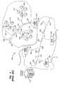
- FIG. 1illustrates a network 100 deploying passive fiber optic lines.
- the network 100may include a central office 110 that connects a number of end subscribers 115 (also called end users 115 herein) within the network 100 .
- the central office 110may additionally connect to a larger network such as the Internet (not shown) and a public switched telephone network (PSTN).
- PSTNpublic switched telephone network
- the network 100may also include fiber distribution hubs (FDHs) 130 having one or more optical splitters (e.g., 1-to-8 splitters, 1-to-16 splitters, or 1-to-32 splitters) that generate a number of individual fibers that may lead to the premises of an end user 115 .
- the various lines of the network 100can be aerial or housed within underground conduits (e.g., see conduit 105 ).
- a portion of the network 100 that is closest to the central office 110is generally referred to as an F 1 region, where F 1 is the “feeder fiber” from the central office 110 .
- the F 1 portion of the network 100may include a distribution cable having on the order of 12 to 48 fibers; however, alternative implementations may include fewer or more fibers.
- a portion of the network 100 that includes at least one of the FDHs 130 and at least one of the end users 115may be referred to as an F 2 portion of the network 100 .
- Splitters used in the typical FDH 130may split incoming fibers of a feeder cable into, for example, 216 to 432 individual distribution fibers that may be associated with a like number of end user 115 locations.
- the network 100includes a plurality of break-out locations 125 at which branch cables 122 are separated out from main cable lines 120 .
- the break-out locations 125can also be referred to as tap locations, drop cable locations, splice locations or branch locations.
- the branch cables 122can also be referred to as drop cables, drop lines, break-out cables or stub cables.
- the branch cables 122are often connected to drop terminals 104 that include connector interfaces for facilitating coupling the fibers of the branch cables 122 to a plurality of different subscriber locations 115 .
- the branch cables 122are also often connected to FDHs 130 .
- incoming optical fibersfrom the central office 110 can be connected to outgoing optical fibers, leading to the end users 115 , forming an optical signal connection.
- Each of the incoming optical fibersmay be split into multiple intermediate fibers.
- Each of these intermediate fibersmay also be connected to one of the outgoing optical fibers, forming an optical signal connection.
- the optical signal connectionscan be reconfigured within the FDH 130 . For example, a particular incoming fiber may be initially connected to a first outgoing fiber but may be disconnected and instead connected to a second outgoing fiber. Certain unused incoming fibers and/or intermediate fibers may not be connected to any of the outgoing fibers.
- the FDH 130may be mounted in various applications and locations. There is a need for the mounting of the FDH 130 to be adaptable to conveniently match various applications and locations. The present disclosure satisfies these and other needs.
- Certain aspects of the disclosurerelate to fiber optic cable systems.
- a fiber optic distribution systemincludes one or more fiber distribution hubs (FDHs) that provide an interface between a central office and subscribers.
- the FDHcontains terminated incoming fibers, coming from the central office, and terminated outgoing fibers, each going to one of the subscribers.
- the terminated outgoing fibersmay be collected at a termination region within the FDH.
- One or more of the incoming fibersmay be connected to an optical splitter within the FDH thereby coupling the incoming fiber to multiple intermediate fibers (e.g., connectorized pigtails).
- the incoming fibers and intermediate fibersmay be selectively connected to the outgoing fibers within the FDH.
- One or more of the incoming fibers and/or the intermediate fibersmay not be connected to any of the outgoing fibers but may instead be parked at a storage module.
- the FDHsmay be mounted in a variety of different locations and in a variety of different applications.
- a common FDH mounting locationis overhead on a mounting pole.
- the mounting polemay also carry an aerially suspended main fiber optic line with a branch line routed to the FDH.
- the FDHis accessed by a technician when it is necessary to establish and/or reconfigure optical connections within the FDH. For example, it may be desired to connect a particular intermediate fiber currently parked at one of the storage modules to a particular outgoing fiber. To reconfigure the optical connections within the FDH, the technician must gain access to the FDH. This may be done by climbing a ladder or the mounting pole itself in the case of the pole mounted FDH.
- Certain embodiments of the present disclosureprovide a ladder bracket for securing the placement of the ladder.
- a cabinet door of the FDHis opened exposing a storage panel.
- the cabinet dooris configured to automatically stop and hold at one or more intermediate locations along its range-of-motion.
- an example storage panelmay be rotatably mounted on a vertical axis or a horizontal axis. The storage panel is opened, exposing multiple parking locations for the storage modules on the storage panel and the termination region behind the storage panel. The desired intermediate fiber is removed from its parking location and connected to the desired outgoing fiber at the termination region. The storage panel is then closed followed by closing (i.e., shutting) the cabinet door.
- the mounting configuration of the FDHmay be chosen based on the specific application. Variables such as the mounting location of the FDH, obstacles surrounding the mounting location of the FDH, and access methods available to the technician to reach the FDH may be considered when choosing the configuration of the FDH.
- the configuration selection of the storage panelmay be jointly considered with the mounting configuration selection of the FDH.
- an example FDHhas three mounting configurations on a mounting pole. The three FDH mounting configurations include a right side mounting configuration, a rear mounting configuration, and a left side mounting configuration.
- the FDH mounting configuration and the storage panel configurationmay be chosen based on convenience of service to the technician.
- an applicationmay have an existing mounting pole available to mount an FDH overhead.
- the example mounting polemay be near existing obstacles which require either the right side mounting configuration or the left side mounting configuration.
- the left side mounting configurationmay be chosen if it offers a suitable ground surface for placement of the ladder.
- the ladder placementprovides the technician with convenient access to the interior of the FDH.
- choosing the vertical axis mounting configuration for the storage panelmay result in screening the technician's view of the termination region when the storage panel is opened.
- the horizontal axis mounting configuration for the storage panelis chosen providing the technician with convenient access to both the storage module(s) and the termination region.
- Other specific applicationsmay favor other mounting configurations for the FDH and the storage panel within the FDH. For example, installations with limited room in front of and no room to the sides of the mounting pole may favor the rear FDH mounting configuration in combination with the vertical axis storage panel mounting configuration.
- an example cabinet doorautomatically stops when opened to a convenient intermediate position (i.e., an intermediate open position) and when fully open (i.e. at a fully opened positioned) and holds at either of these positions.
- the door stopping and holding featureis especially useful in windy conditions at pole mounted FDH installations requiring a ladder for access. At such installations, the door may be difficult to reach and close if opened beyond the intermediate position. With the door held at the intermediate position, the servicing technician is able to grab and close the door without stretching to reach it or dismounting from and repositioning the ladder to reach it.
- the servicing technicianmay find it necessary to dismount from and reposition the ladder or may find it necessary to stretch to be able to reach the door.
- repositioning the laddermay preclude the use of the ladder bracket and is therefore undesired.
- having the FDH door held at the intermediate or fully open positionfrees the technician from holding the door while servicing the FDH. To release the FDH door from the holding positions, a door stay assembly is lifted while the door is closed. In certain embodiments, more than one intermediate position may be provided.
- the ladder bracketis reconfigurable and can also function as an FDH support bracket.
- the ladder bracket configurationcan compliment the FDH mounting configuration functioning as a support bracket in certain configurations and functioning as a ladder bracket in other configurations.
- the example ladder bracketfunctions as a ladder support when the FDH is mounted in the rear mounting configuration and functions as an FDH support bracket when the FDH is mounted in the right side mounting configuration or the left side mounting configuration.
- the ladder bracketwhen functioning as a ladder support, supports the ladder in a position convenient for the technician when servicing the FDH.
- FIG. 1shows a prior art passive fiber optic network
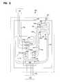
- FIG. 2is a schematic diagram showing an example cable routing scheme for a fiber distribution hub
- FIG. 3is a perspective view showing a front, top, and left side of an example fiber distribution hub having a cabinet with a front door shown in an open position and a hinged storage panel configured in a vertical hinge configuration shown in a closed position;
- FIG. 4shows an enlarged exploded portion of FIG. 3 illustrating a first hinge mounting position for mounting a hinge resulting in the vertical hinge configuration of FIG. 3 ;
- FIG. 5shows an enlarged exploded portion of FIG. 3 illustrating a second hinge mounting position with a stop plate mounted thereon;
- FIG. 6is a perspective view showing the front, top, and a right side of the example fiber distribution hub of FIG. 3 having the front door removed and the vertically configured hinged storage panel shown in an open position;
- FIG. 7shows an enlarged portion of FIG. 6 illustrating a parking location holding a storage module on the hinged storage panel of FIG. 3 ;
- FIG. 8is a perspective view showing a rear, top, and right side of the storage module of FIG. 7 ;
- FIG. 9is a perspective view showing the rear, top, and a left side of the storage module of FIG. 7 holding a connectorized fiber and a connector dust cap;
- FIG. 10is a perspective view showing the front, top, and right side of the example fiber distribution hub of FIG. 3 having the front door removed and the vertically configured hinged storage panel shown in the open position of FIG. 6 , the view illustrating an example cable/fiber route from a splitter module mounted on a swing frame to the storage module of FIG. 7 mounted on the hinged storage panel of FIG. 3 ;
- FIG. 11is a perspective view showing the front, top, and left side of the example fiber distribution hub of FIG. 3 with the front door in the open position and the hinged storage panel configured in a horizontal hinge configuration shown in a closed position;
- FIG. 12shows an enlarged exploded portion of FIG. 11 illustrating the first hinge mounting position of FIG. 4 with the stop plate of FIG. 5 mounted thereon;
- FIG. 13shows an enlarged exploded portion of FIG. 11 illustrating a third hinge mounting position for mounting the hinge of FIG. 4 resulting in the horizontal hinge configuration of FIG. 11 ;
- FIG. 14is a perspective view showing the front, top, and left side of the example fiber distribution hub of FIG. 3 with the horizontally configured hinged storage panel shown in another open position;
- FIG. 15shows an enlarged portion of FIG. 14 illustrating a storage panel support cable with a ring terminal and a storage panel support hook
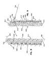
- FIG. 16is a perspective view showing a rear, the top, and the right side of the example fiber distribution hub of FIG. 3 , the view illustrating an entrance location for incoming fibers and an exit location for outgoing fibers;
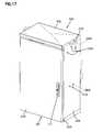
- FIG. 17is a perspective view showing the front, top, and left side of the example fiber distribution hub of FIG. 3 with the front door shown in a closed position;
- FIG. 18is a partially exploded perspective view showing the front, top, and left side of the example fiber distribution hub of FIG. 3 and a set of mounting brackets configured on the left side;
- FIG. 19is an exploded perspective view showing a front, top, and left side of a mounting pole including a mounting bracket receiver;
- FIG. 20is a partially exploded perspective view showing the front, top, and left side of the example fiber distribution hub of FIG. 3 with the set of mounting brackets of FIG. 18 installed and mounted to the mounting pole of FIG. 19 in a left mounting configuration;
- FIG. 21is a perspective view showing the front, top, and left side of the example fiber distribution hub of FIG. 3 with the front door shown in the open position and the swing frame of FIG. 10 shown in a service position;
- FIG. 22is a partial perspective view showing the front, top, and leftward side of the example fiber distribution hub of FIG. 3 with the front door in the open position and a door stay assembly in an intermediate holding position;
- FIG. 23is a partial perspective view showing the front, top, and leftward side of the example fiber distribution hub of FIG. 3 with the front door in the open position and the door stay assembly of FIG. 22 removed to fully reveal a door holding slot;
- FIG. 24is a partial perspective view showing the front, bottomward, and leftward side of the example fiber distribution hub of FIG. 3 with the front door in the open position and the door stay assembly of FIG. 22 in the intermediate holding position;
- FIG. 25is a partial perspective view showing the front, bottomward, and leftward side of the example fiber distribution hub of FIG. 3 with the front door in the open position and the door stay assembly of FIG. 22 removed to fully reveal the door holding slot of FIG. 23 ;
- FIG. 26is a perspective view showing the bottom of the door stay assembly of FIG. 22 ;
- FIG. 27is a perspective view showing the top of the door stay assembly of FIG. 22 ;
- FIG. 28is an exploded perspective view showing the top of the door stay assembly of FIG. 22 ;
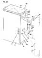
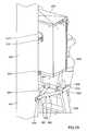
- FIG. 29is a perspective view showing the rear, the top, and the right side of the example fiber distribution hub of FIG. 3 mounted on the pole of FIG. 19 in a rear mounting configuration and a ladder bracket also mounted to the pole beneath the fiber distribution hub;
- FIG. 30is the same view as FIG. 29 but shows an upper component of the ladder bracket through the pole;
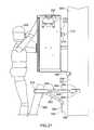
- FIG. 31is an elevation view showing the left side of the example fiber distribution hub of FIG. 3 mounted on the pole of FIG. 19 in the rear mounting configuration and the ladder bracket of FIG. 29 also mounted to the pole beneath the fiber distribution hub;
- FIG. 32is a perspective view showing the rear, top, and right side of the example fiber distribution hub of FIG. 3 mounted to the mounting pole of FIG. 19 in a left mounting configuration and the ladder bracket of FIG. 29 serving as a support bracket;
- FIG. 33is an elevation view showing the front of the example fiber distribution hub of FIG. 3 mounted to the mounting pole of FIG. 19 in a left mounting configuration and the ladder bracket of FIG. 29 serving as a support bracket.
- a fiber optic distribution systemincludes one or more fiber distribution hubs (FDHs) that provide an interface between a central office 110 and subscribers 115 .
- the FDHcontains terminated incoming fibers, coming from the central office 110 , and terminated outgoing fibers, each going to one of the subscribers 115 .
- Optical connections between the incoming fibers and the outgoing fibersmay be established and rearranged within the FDH.
- a hinged storage paneldescribed and illustrated in example embodiments below, provides multiple mounting locations for multiple storage modules. The storage modules organize and hold the terminated incoming fibers until they are connected to the terminated outgoing fibers at a termination region, also described in example embodiments below.
- the hinged storage panelcovers the termination region unless and until the FDH is being serviced (e.g., when optical connections are being established and/or rearranged).
- the hinged storage paneluncovers the termination region and holds the storage modules in convenient proximity to the termination region. This convenient proximity facilitates manually establishing and switching the optical connections between the storage modules and the termination region.
- the hinged storage panelis mountable to multiple configurations and is mounted on at least one variable position hinge. A configuration for the hinged storage panel is chosen based upon the given application and mounting location of the FDH among other things.
- the FDHincludes a cabinet enclosing the optical connections, the hinged storage panel, the termination region, and other components when closed.
- the cabinetis openable to expose the optical connections, the hinged storage panel, the termination region, and other components when being serviced.
- the FDH cabinetis mountable in multiple configurations and locations in various environments.
- FDH mounting locationsinclude overhead on a mounting pole, on a wall, on a pedestal, and within an underground vault.
- Various environmentsmay include obstacles near the FDH that interfere with access to the FDH and the servicing of the FDH.
- a mounting configuration for the FDH cabinetis chosen based upon the given application, mounting location, and environment of the FDH.
- the combination of the hinged storage panel configuration and the FDH cabinet mounting configurationmay be considered together, further matching the overall FDH configuration to the given application, mounting location, and environment.
- An example FDH cabinetincludes multiple mounting areas each adapted for fastening to a mounting bracket set to facilitate the multiple mounting configurations.
- the mounting bracket setis adapted to mount the FDH cabinet at one of the mounting areas to a mounting pole.
- another mounting bracket setmay be adapted to mount the FDH cabinet at one of the mounting areas to, for example, a wall, an underground vault, or other mounting location.
- the example FDH cabinetfurther includes a cabinet door configured to automatically stop and hold at one or more intermediate positions along its range-of-motion.
- the cabinet doorincludes stop-and-hold features that automatically stop the door when it is opened approximately 90 degrees and 135 degrees and holds the door at these positions.
- the stop-and-hold featuresmay be effective at other door positions including at the door's range-of-motion limits.
- the door stop-and-hold functionaids in servicing the FDH especially in windy conditions. To release the FDH door from the holding positions, a door stay assembly is lifted while the door is closed.
- the stop-and-hold functionmay be included in one or more of the doors.
- FIG. 2is a schematic diagram showing an example cable routing scheme for example FDH 200 .
- the FDH 200generally administers connections at a termination region 311 between incoming fibers and outgoing fibers in an Outside Plant (OSP) environment.
- OSPOutside Plant
- a connectionbetween fibers includes both direct and indirect connections.
- incoming fibersinclude feeder cable 700 fibers that enter the FDH 200 and intermediate fibers (e.g., connectorized pigtails 704 extending from splitters 500 and patching fibers/jumpers) that connect the feeder cable 700 fibers to the termination region 311 .
- intermediate fiberse.g., connectorized pigtails 704 extending from splitters 500 and patching fibers/jumpers
- Examples of outgoing fibersinclude subscriber cable 708 fibers that exit the FDH 200 and any intermediate fibers that connect the subscriber cable 708 fibers to the termination region 311 .
- the FDH 200provides an interconnect interface for optical transmission signals at a location in the network where operational access and reconfiguration are desired.
- the FDH 200can be used to split the feeder cables 700 and connect the split feeder cables 700 to distribution cables 708 routed to subscriber locations 115 .
- the FDH 200is designed to accommodate a range of alternative sizes and fiber counts and support factory installation of pigtails 704 , fanouts, and splitters 500 .
- the feeder cable 700is initially routed into the example FDH 200 through a cabinet 201 (e.g., typically through the back or bottom of the cabinet 201 as shown at FIG. 16 ).
- the fibers of the feeder cable 700can include ribbon fibers.
- An example feeder cable 700may include twelve to forty-eight individual fibers connected to the service provider's central office 110 .
- the fibers of the feeder cable 700are routed to a feeder cable interface 800 (e.g., fiber optic adapter modules, a splice tray, etc.).
- a feeder cable interface 800e.g., fiber optic adapter modules, a splice tray, etc.
- the splitter input fibers 702are routed from the feeder cable interface 800 to a splitter mounting location 322 at which a plurality of splitter modules 500 can be mounted.
- Each splitter module 500includes at least one fiber optic splitter 501 positioned within a splitter housing 503 .
- the splitter input fibers 702are optically connected to separate splitter modules 500 , wherein the input fibers 702 are each split by the fiber optic splitters of the splitter module 500 into multiple pigtails 704 , each having a connectorized end 706 .
- the fibers of the feeder cable 700can be connectorized and can be routed directly to the splitter modules 500 thereby bypassing or eliminating the need for an intermediate feeder cable interface 800 .
- the connectorized ends 706can be temporarily stored on a storage module 600 that is mounted at a storage region 313 of a swing frame 300 .
- the pigtails 704are routed from the splitter modules 500 to a termination module 400 that is provided at the termination region 311 of the swing frame 300 .
- the connectorized ends 706 of the pigtails 704are connected to the connectorized ends 710 of the fibers of the distribution cable 708 within an adaptor 450 .
- the termination region 311is the dividing line between the incoming fibers and the outgoing fibers.
- a typical distribution cable 708forms the F 2 portion of a network (see FIG. 1 ) and typically includes a plurality of fibers (e.g., 144, 216 or 432 fibers) that are routed from the FDH 200 to subscriber locations 115 .
- one or more of the fibers of the feeder cable 700are not connected to any of the splitter modules 500 . Rather, these fibers of the feeder cable 700 are connected to pass-through fibers 712 having connectorized ends 714 .
- the pass-through fibers 712are connected to the termination modules 400 , without first connecting to the splitter modules 500 . By refraining from splitting the fiber 712 , a stronger signal can be sent to one of the subscribers.
- the connectorized ends 714 of the pass-through fibers 712can be stored at the storage region 313 when not in use.
- the splitter modules 500 and storage modules 600can be incrementally added to the swing frame 300 .
- the connectorized pigtails 704are typically stored in one or more storage modules 600 prior to installation on the swing frame 300 .
- the connector 706 of each pigtail 704is secured in a storage module 600 before the splitter module 500 leaves the factory.
- the storage module 600includes a body 610 having a front side 602 , a rear side 604 , a top, and a bottom.
- the body 610is configured to hold at least one fiber connector 706 within at least one port 606 .
- the body 610is configured to hold about sixteen connectors 706 and includes about sixteen ports 606 .
- the body 610is arranged to retain the fiber connectors 706 in a single row configuration. In other embodiments, the body 610 can be arranged to hold the connectors 706 in a square pattern or in any other desired configuration.
- an adapter dust plug 453can be stored within the port 606 .
- a plurality of dust cap holders 616are provided on the body 610 to store connector 706 dust caps 458 .
- a latch 612is provided near the top of the body 610 and a tab 614 is provided near the bottom for mounting purposes. More information regarding the storage modules 600 can be found at U.S. Pat. No. 7,198,409, issued on Apr. 3, 2007, entitled FIBER OPTIC CONNECTOR HOLDER AND METHOD; at U.S. Pat. No. 7,233,731, issued on Jun. 19, 2007, entitled TELECOMMUNICATIONS CONNECTION CABINET; and at U.S. Pat. No. 7,218,827, issued on May 15, 2007, entitled MULTI-POSITION FIBER OPTIC CONNECTOR HOLDER AND METHOD which are hereby incorporated by reference in their entirety.
- the storage region 313is defined in part by a variable position, hinged storage panel 250 .
- the storage panel 250includes a plurality of upper openings 266 and a plurality of lower openings 268 .
- the latch 612 of the storage module 600is designed to removably snap into any of the upper openings 266 while the tab 614 is engaged in a paired lower opening 268 .
- Each of the opening 266 , 268 pairsdefines a storage module 600 mounting location 264 which can be arranged in any desired configuration within the storage panel 250 .
- the storage panel 250defines twenty-two of the storage module 600 mounting locations 264 .
- Each of the opening 266 , 268 pairsis configured to receive a storage module body 610 arranged to retain sixteen fiber connectors 706 in a row.
- Other embodimentsmay employ fewer or more than twenty-two of the mounting locations 264 and may employ storage module bodies arranged to retain fewer or more than sixteen fiber connectors 706 .
- the corresponding storage modules 600are loaded onto the storage panel 250 .
- the pigtail 704 sets extending from the splitter modules 500 to the storage modules 600are routed along a path 705 through one or more guide rings 270 that allows the hinged storage panel 250 to rotate through a desired range-of-motion.
- the range-of-motionincludes an open position (see FIGS. 6 , 10 , 14 , and 15 ) and a closed position (see FIGS. 3 and 11 ) of the hinged storage panel 250 .
- the open positioncan be one of several open positions depending on the configuration of the hinged storage panel 250 as will be further described hereinafter.
- FIGS. 6 and 10show one open position of the hinged storage panel 250
- FIGS. 14 and 15show another open position.
- the hinged storage panel 250is moveable between the closed position and the open position.
- the hinged storage panel 250is typically in the closed position when the FDH 200 is in normal service and when the FDH 200 is being stored or transported (e.g., before the FDH 200 is initially installed).
- the hinged storage panel 250is typically moved to the open position when certain service operations are performed on the FDH 200 by the technician (e.g., the connectorized ends 706 are reconfigured between being stored on the hinged storage panel 250 and being placed in service on the termination region 311 of the swing frame 300 ). After the service operation is completed, the hinged storage panel 250 is typically returned to the closed position.
- the example FDH 200includes the example cabinet 201 that houses internal components.
- the example cabinet 201has a top panel 202 , a bottom panel 203 , a left side panel 204 , a back panel 205 , and a right side panel 206 .
- At least one cabinet door 210covers the cabinet 201 front when closed.
- the door 210is rotatably mounted to the cabinet 201 by at least one hinge 214 and is secured to the cabinet 201 by a door latch 211 when closed.
- the door 210is held at certain open positions by a door stay assembly 230 further described below.
- the cabinet 201includes an opening 722 through which the feeder cable (e.g., or F 1 cable) 700 enters and another opening 724 through which the subscriber cable 708 exits the cabinet 201 .
- the example FDH cabinet 201includes three sets of mounting holes 280 b , 280 l , and 280 r , each set 280 b , 280 l , 280 r defining a separate mounting area.
- the mounting hole set 280 bfacilitates mounting the FDH 200 on its back panel 205 .
- the mounting hole set 280 rfacilitates right side panel 206 mounting and the mounting hole set 280 l facilitates left side panel 204 mounting.
- two or fewer mounting area(s)may be provided.
- four or more mounting areasmay be provided.
- the cabinet 201 of the FDH 200is configured to protect the internal components against rain, wind, dust, rodents and other contaminants.
- the cabinet 201remains relatively lightweight for easy installation and breathable to prevent accumulation of moisture in the FDH 200 .
- an aluminum construction with a heavy powder coat finishalso provides for corrosion resistance.
- the cabinet 201is manufactured from heavy gauge aluminum and is NEMA-4X rated. In other embodiments, however, other materials can also be used.
- loops 218can be provided on the cabinet 201 for facilitating deployment of the cabinet 201 at a desired location.
- the loops 218can be used to position the cabinet 201 using a crane.
- the cranecan lower the cabinet 201 into an underground region.
- the loops 218are removable or can be adjusted to not protrude from the top cabinet panel 202 .
- the swing frame 300is pivotably mounted on hinges 355 within and to the cabinet 201 and supports the termination region 311 among other things.
- the swing frame 300is moveable between a stowed position (see FIGS. 3 , 10 , 11 , and 14 ) and a service position (see FIG. 21 ).
- the swing frame 300is typically in the stowed position when the FDH 200 is in normal service and when the FDH 200 is being stored or transported (e.g., before the FDH 200 is initially installed).
- the swing frame 300is typically moved to the service position when certain service operations are performed on the FDH 200 by the technician (e.g., when reconfiguring, adding, or removing the pigtails 704 , the fanouts, the splitters 500 , the feeder cable 700 , the feeder cable interface 800 , the splitter input fibers 702 , etc.) After the service operation is completed, the swing frame 300 is typically returned to the stowed position.
- the swing frame 300includes a top panel 320 , a bottom panel 330 , a left panel 340 , and a rear portion 336 .
- the storage panel 250is mounted to the swing frame 300 with a pair of variable position hinges 252 and can hold at least one storage module 600 .
- the storage panel 250can be configured with a vertical axis hinge 252 mount or a horizontal axis hinge 252 mount.
- the storage panel 250includes a first set and a second set of vertical hinge mounting holes 253 v matched to two sets of vertical hinge mounting holes 255 v included on the swing frame 300 .
- the vertical axis hinge 252 configurationis obtained by fastening one of the hinges 252 to the first set of mount holes 253 v , 255 v and the other hinge 252 to the second set of mounting holes 253 v , 255 v .
- the storage panel 250includes a first set and a second set of horizontal hinge mounting holes 253 h matched to two sets of horizontal hinge mounting holes 255 h included on the swing frame 300 .
- the horizontal axis hinge 252 configurationis obtained by fastening one of the hinges 252 to the first set of mount holes 253 h , 255 h and the other hinge 252 to the second set of mounting holes 253 h , 255 h .
- a stop plate 254is provided to stop the storage panel 250 at the closed position in both the horizontal and vertical axis hinge 252 configurations. As illustrated at FIGS.
- the stop plate 254is fastened to the set of horizontal hinge mounting holes 253 h farthest from the hinges 252 when the storage panel 250 is in the vertical axis hinge 252 configuration. Similarly, as illustrated at FIGS. 11 and 12 , the stop plate 254 is fastened to the set of vertical hinge mounting holes 253 v farthest from the hinges 252 when the storage panel 250 is in the horizontal axis hinge 252 configuration.
- a latch 256is provided on the storage panel 250 to secure the storage panel 250 when in the closed position.
- a support member 258e.g. a support cable
- a first end of the support member 258is attached to the swing frame 300 .
- a second end of the support member 258is terminated by a ring terminal 260 .
- a hook 262is provided on the storage panel 250 .
- the ring terminal 260is preferably attached to the hook 262 when the storage panel 250 is in the horizontal hinge 252 configuration.
- Other embodimentsmay provide other means to provide a horizontally and a vertically hinged mount for the storage panel 250 .
- Other embodimentsmay provide other means for stopping and latching the storage panel 250 .
- FIGS. 16 through 20an example FDH mounting system is illustrated for mounting the FDH 200 to a mounting pole 550 in three configurations.
- the three configurationscorrespond with the three sets of mounting holes 280 b , 280 l , and 280 r , provided on the example FDH cabinet 201 as mentioned above.
- a clip plate 570 and a bottom bracket 580are fastened to one of the three sets of mounting holes 280 b , 280 l , or 280 r .
- the mounting hole set 280 bis used.
- the mounting hole set 280 ris used for a right side panel 206 mounting configuration
- mounting hole set 280 lis used for a left side panel 204 mounting configuration.
- FIGS. 18 and 20illustrate the left side panel 204 mounting configuration with the clip plate 570 fastened through mounting holes 578 , provided at a mounting flange 571 , with mounting fasteners 579 at an upper three of the mounting holes of the set 280 l . Additionally, the bottom bracket 580 is fastened through mounting holes 582 , provided at a cabinet mounting flange 586 , with additional mounting fasteners 579 at a lower two of the mounting holes of the set 280 l.
- the mounting pole 550is prepared to receive the FDH 200 by attaching a pole mounting bracket 560 to the pole 550 as illustrated at FIG. 19 .
- a thru hole 552is prepared on the pole 550 and a thru fastener 568 is inserted through a mounting hole 562 , provided on the bracket 560 , and the thru hole 552 .
- a nut 569retains the thru fastener 568 and is tightened, drawing an upper and a lower pole cradle 563 of the bracket 560 toward the pole 550 .
- the pole cradles 563are shaped to engage an outer surface 551 of the pole 550 thereby preventing rotation of the pole mounting bracket 560 .
- the pole mounting bracket 560further includes a pair of clip support flanges 566 and a pair of cabinet support flanges 564 to engage and support the FDH cabinet 201 with the attached clip plate 570 , further described below.
- FIG. 20illustrates a mounting method that mounts the FDH 200 to the mounting pole 550 .
- the FDH 200 with the clip plate 570 and the bottom bracket 580 pre-assembled, as described above,may be hung from the mounting pole 550 with the pole mounting bracket 560 pre-assembled, also described above.
- Hanging the FDH 200 from the mounting pole 550does not require installing fasteners but instead relies on a clip tab 572 of the clip plate 570 being inserted within a clip slot 567 defined on the pole mounting bracket 560 .
- the clip tab 572 and clip slot 567act in conjunction with a pair of retaining fingers 576 that engage the cabinet support flanges 564 .
- the retaining fingers 576may be spring loaded providing a tight, rattle free connection by squeezing the cabinet support flanges 564 against the cabinet 201 .
- the hangingrelies on a pair of pole mounting flanges 588 , which form a saddle shape (e.g., a “V” shape) on the bottom bracket 580 , engaging the outer surface 551 of the mounting pole 550 and a stop pad 574 on the clip plate 570 engaging a pair of clip support flanges 566 on the pole mounting bracket 560 .
- the FDH 200is raised such that the bottom of the attached clip tab 572 is positioned above the clip slot 567 and the outer surface 551 of the mounting pole 550 is nestled within the “V” shape of the pair of the attached pole mounting flanges 588 .
- Such a positionis the clip tab 572 engagement position.
- the “V” shapemay radially guide the FDH 200 into a radial engagement position about the mounting pole 550 .
- the loops 218are provided to facilitate raising the FDH 200 by a crane.
- the crane positionmay be adjusted to move the FDH 200 into a vertical engagement position.
- a tangential engagement position of the FDH 200may be obtained with lateral movements of the crane or, if near the clip tab 572 engagement position, manual force may be used.
- the FDH 200is lowered, resulting in the clip tab 572 engaging the clip slot 567 .
- the FDH 200is further lowered until the stop pad 574 on the clip plate 570 rests against the clip support flanges 566 on the pole mounting bracket 560 .
- the FDH 200is in a stable hanging position on the mounting pole 550 without additional fasteners.
- a tipping momentis created by an offset between a center of gravity of the FDH 200 and vertical support at the stop pad 574 .
- the tipping momentis balanced by a lateral support, provided by the clip slot 567 , pulling the FDH 200 towards the mounting pole 550 coupled by another lateral support, provided by the mounting pole 550 , pushing the FDH 200 away at the bottom bracket 580 .
- the pushing action between the mounting pole 550 and the bottom bracket 580occurs at the “V” shape of the pair of pole mounting flanges 588 , stabilizing the FDH 200 .
- a pair of pole fasteners 589is inserted through a pair of pole mounting holes 584 , provided at the pair of pole mounting flanges 588 , and screwed into the mounting pole 550 at a pair of screw locations 554 .
- the pair of pole fasteners 589prevents the bottom bracket 580 from separating from the mounting pole 550 during disturbances such as a wind storm.
- the pole mounting fastenersprevent the clip tab 572 from being pulled out of the clip slot 567 and the retaining fingers 576 from being pulled off of the cabinet support flanges 564 .
- a ladder bracket 920is provided and can serve several functions as illustrated at FIGS. 29 through 33 .
- the ladder bracket 920may be mounted in several configurations depending on the mounting location and the mounting configuration of the FDH 200 .
- FIGS. 29 through 31illustrate the FDH 200 mounted on the mounting pole 550 in the back panel 205 mounting configuration and the ladder bracket 920 serving as a ladder 926 support.
- FIGS. 32 and 33illustrate the FDH 200 mounted on the mounting pole 550 in the left side panel 204 mounting configuration and the ladder bracket 920 (with certain parts removed) serving as an FDH 200 mounting bracket.
- FIGS. 29 through 31illustrate the FDH 200 mounted
- an upper component 940 of the ladder bracket 920may support the FDH 200 and connect the FDH 200 to the pole 550 with the FDH 200 in the left side panel 204 mounting configuration or the right side panel 206 mounting configuration. This support and connection may be in conjunction with the brackets 560 , 570 , and 580 of the preceding paragraphs or may be with the ladder bracket 920 (or component thereof) acting alone.
- the ladder bracket 920is shown mounted to the pole 550 (e.g., a telephone pole) at a location beneath the FDH 200 .
- a ladder 926is shown supported by the ladder bracket 920 .
- an upper hook 928 of the ladder 926is shown hooked over the ladder bracket 920 .
- Lateral guide posts 970can be included with the ladder bracket 920 to keep the ladder 926 from laterally slipping off the ladder bracket 920 .
- the lateral guide posts 970are especially useful in preventing a ladder without upper hooks 928 from slipping laterally off of the ladder bracket 920 .
- a servicing technician 930is shown standing on the ladder 926 at a position suitable for accessing the interior of the FDH 200 .
- the ladder bracket 920includes the generally U-shaped upper component 940 and an angled support component 962 .
- the upper component 940includes a central rung portion 944 over which the hooks 928 of the ladder 926 can be hooked.
- the central rung portion 944can also provide support for the ladder 926 directly and also can support a ladder without hooks 928 .
- the upper component 940includes first and second ends 937 and 939 .
- the upper component 940also includes rearward extensions 946 (e.g., legs, members, struts, bars, rods, etc.) having forward ends connected to the first and second ends 937 and 939 of the central rung portion 944 and rearward ends that are rearwardly offset from the central rung portion 944 .
- Lateral flanges 948are positioned at the rearward ends of the rearward extensions 946 .
- the lateral flanges 948define openings 950 for receiving fasteners used to secure the flanges 948 to opposite sides of the pole 550 .
- the flanges 948 shown positioned at opposite sides of the pole 550such that the pole 550 is positioned directly between the lateral flanges 948 (i.e., rearward extensions 946 straddle the pole 550 ).
- Example fasteners suitable for securing the flanges 948 to the pole 550include lag bolts.
- the angled support component 962is adapted for reinforcing the upper component 940 such that the upper component 940 is held in a generally horizontal orientation.
- the angled support component 962extends downwardly from the upper component 940 and is preferably aligned at an acute angle relative to the upper component 940 .
- the angled support component 962can be pivotally moveable relative to the upper component 940 (e.g., through the use of pivot bearings, T-collars or other structures) such that the angular relation between the upper component 940 and the angled support component 962 can be adjusted during installation.
- the angled support component 962includes a base end 960 .
- a forward end of the angled support component 962is secured to the central portion 944 of the upper component 940 .
- the base end 960 of the angled support component 962is attached to a lower flange 964 .
- the lower flange 964includes one or more fastener openings 965 for allowing the flange 964 to be fastened to the pole 550 .
- a spacer(not shown) may be inserted between the lower flange 964 and the pole 550 .
- the lower flange 964is secured to a front side of the pole 550
- the flanges 948are secured to left and right sides of the pole 550 .
- the lower flange 964is secured to the pole 550 by fasteners such as lag bolts.
- the central rung portion 944is preferably located below the fiber distribution hub 200 and forwardly offset from the pole 550 .
- the ladder bracket 920is shown in a configuration serving as one of the FDH 200 support brackets.
- the lateral flanges 948 of the ladder bracket 920are near the pole 550 and can be joined to the pole 550 by suitable combinations of fasteners and/or brackets (e.g., angle brackets).
- the central portion 944 and the lateral guide posts 970 of the upper component 940are near the center of the back panel 205 of the FDH cabinet 201 .
- the clip plate 570attaches to the lateral guide posts 970 between the retaining fingers 576 and the clip tab 572 (see FIG. 18 ).
- fastenersare used to secure the ladder bracket 920 to the FDH cabinet 201 .
- the angled support component 962has been removed from the embodiment illustrated in FIG. 32 .
- the angled support component 962can remain attached and can serve as a third attachment point to the pole 550 (the pole 550 being cradled between the lateral flanges 948 and the base end 960 ).
- the FDH 200can be further tailored to a variety of specific applications.
- the door stay assembly 230in cooperation with a pivot mount 233 , fixedly attached to the FDH cabinet 201 (see FIG. 25 ), and a door holding slot 240 , included within the FDH cabinet door 210 , function to stop and hold the door 210 .
- a first end 232 of the door stay assembly 230is rotatably mounted at the pivot mount 233 .
- a second end 234 of the door stay assembly 230is slidably mounted along the door holding slot 240 .
- the first end 232 and the second end 234 of the door stay assembly 230may both be formed in and joined by a bar 238 (see FIG.
- the door stay assembly 230moves in a predetermined manner, guided by the pivot mount 233 and the door holding slot 240 .
- One or more stop positions 244are included along the door holding slot 240 .
- the stop positions 244engage certain features mounted on the second end 234 of the door stay assembly 230 automatically as the second end 234 slides along the door holding slot 240 . This engagement stops and holds the second end 234 at the given stop position 244 preventing further sliding until the engagement is released.
- the cabinet door 210is also stopped and held.
- a bearing mountmay be used.
- a pivot hole 235is provided at the first end 232 of the door stay assembly 230 (see FIG. 28 ).
- the pivot hole 235is mounted around a sleeve 231 of the pivot mount 233 .
- the pivot mount 233further captures and retains the first end 232 of the door stay assembly.
- a slide mount 245includes a mounting flange 249 fixedly mounted to an opening 236 on the second end 234 of the door stay assembly 230 (see FIGS. 26 through 28 ).
- the slide mount 245further includes a sliding diameter 246 positioned between an engaging diameter 247 and a retaining flange 248 .
- the sliding diameter 246is sized to slide along and within a guide slot portion(s) 242 of the door holding slot 240 .
- the engaging diameter 247is sized larger than a width of the guide slot portion(s) 242 and smaller than the stop position(s) 244 of the door holding slot 240 .
- the retaining flange 248is sized larger than both the width of the guide slot portion(s) 242 and the stop position(s) 244 of the door holding slot 240 .
- the slide mount 245is therefore slidingly held by the guide slot portion(s) 244 along its length and retains the door stay assembly 230 to the door holding slot 240 .
- the slide mount 245Upon opening the cabinet door 210 , the slide mount 245 is initially held by and slides within a first guide slot portion 242 . Continuing to open the cabinet door 210 further slides the slide mount 245 along the first guide slot portion 242 until it reaches a first stop position 244 along the door holding slot 240 (see FIG. 25 ). An intermediate open position of the cabinet door 210 is held when the slide mount 245 engages the first stop position 244 . As mentioned above, the engaging diameter 247 is sized smaller than the stop position(s) 244 . Therefore, upon reaching the first stop position 244 , gravity pulls the door stay assembly 230 down causing the engaging diameter 247 to occupy the first stop position 244 .
- the door stay assembly 230may be manually lifted, raising the engaging diameter 247 out of the stop position 244 .
- the cabinet door 210may be moved slightly causing the slide mount 245 to move off of the stop position 244 . If the cabinet door 210 is opened beyond the intermediate open position to a fully open position, the fully open position of the cabinet door 210 is held when the slide mount 245 engages the second stop position 244 at an end of the door holding slot 240 (see FIGS. 24 and 25 ).
- methods not relying on gravitymay be used to engage the stop position 244 and the engaging diameter 247 .
- the bar 238may be spring loaded and urge such engagement.
- the FDH cabinet door 210 stop and hold features described aboveare especially useful in conjunction with the ladder bracket 920 also described above. It is often desired for the servicing technician 930 to be able to remain in the same position on the ladder 926 while servicing the FDH 200 . By controlling and limiting the door 210 opening position, the door 210 remains within convenient reach of the servicing technician 930 while on the ladder 926 held in position by the ladder bracket 920 (see FIG. 31 ).
- the hingesincluding the hinges 214 , 252 , and 355 , include hinges with simple hinging lines, flexible hinging members, hinges not having simple hinging lines, hinges having pivoting members, hinges having linkages, etc.
- the hinging axis or axes of such hingescan have a fixed position with respect to the hinge or have a non-fixed position.
- the hinging axisdoes not necessarily coincide with a physical feature of the hinge and can be a virtual axis that varies in position as the hinge moves through its range of motion.
Landscapes
- Physics & Mathematics (AREA)
- General Physics & Mathematics (AREA)
- Optics & Photonics (AREA)
- Light Guides In General And Applications Therefor (AREA)
Abstract
Description
Claims (21)
Priority Applications (1)
| Application Number | Priority Date | Filing Date | Title |
|---|---|---|---|
| US12/276,005US8229265B2 (en) | 2007-11-21 | 2008-11-21 | Fiber distribution hub with multiple configurations |
Applications Claiming Priority (3)
| Application Number | Priority Date | Filing Date | Title |
|---|---|---|---|
| US395507P | 2007-11-21 | 2007-11-21 | |
| US99060907P | 2007-11-27 | 2007-11-27 | |
| US12/276,005US8229265B2 (en) | 2007-11-21 | 2008-11-21 | Fiber distribution hub with multiple configurations |
Publications (2)
| Publication Number | Publication Date |
|---|---|
| US20090263096A1 US20090263096A1 (en) | 2009-10-22 |
| US8229265B2true US8229265B2 (en) | 2012-07-24 |
Family
ID=41201173
Family Applications (1)
| Application Number | Title | Priority Date | Filing Date |
|---|---|---|---|
| US12/276,005Active2031-01-21US8229265B2 (en) | 2007-11-21 | 2008-11-21 | Fiber distribution hub with multiple configurations |
Country Status (1)
| Country | Link |
|---|---|
| US (1) | US8229265B2 (en) |
Cited By (13)
| Publication number | Priority date | Publication date | Assignee | Title |
|---|---|---|---|---|
| US20150370025A1 (en)* | 2014-06-23 | 2015-12-24 | Adc Telecommunications, Inc. | Bladed chassis systems |
| US9816304B2 (en) | 2014-09-11 | 2017-11-14 | Commscope Technologies Llc | Door hinge mechanism for telecommunications panel |
| US10031306B2 (en) | 2015-02-27 | 2018-07-24 | Opterna Technology Limited | Fiber distribution assemblies |
| US10036865B2 (en) | 2016-09-16 | 2018-07-31 | Corning Research & Development Corporation | Parking door assemblies for use with fiber distribution hubs and methods of installing parking door assemblies |
| US10278298B2 (en) | 2014-07-22 | 2019-04-30 | CommScope Connectivity Belgium BVBA | Door hinge mechanism for telecommunications panel |
| US20190196127A1 (en)* | 2017-12-27 | 2019-06-27 | Afl Ig Llc | Optical distribution frames |
| US10539757B2 (en) | 2016-04-19 | 2020-01-21 | Commscope, Inc. Of North Carolina | Telecommunications chassis with slidable trays |
| US10935745B1 (en) | 2017-07-20 | 2021-03-02 | Forrest Tyrone Gay | Multi-carrier fiber distribution hub |
| US11022770B2 (en) | 2015-07-29 | 2021-06-01 | Commscope Technologies Llc | Bladed chassis systems |
| US20210176888A1 (en)* | 2019-08-05 | 2021-06-10 | Panduit Corp. | Cable manager with a hinged door |
| US11674345B2 (en) | 2016-04-19 | 2023-06-13 | Commscope, Inc. Of North Carolina | Door assembly for a telecommunications chassis with a combination hinge structure |
| US12298581B2 (en) | 2020-01-29 | 2025-05-13 | Afl Telecommunications Llc | Terminal enclosure for a telecommunications system |
| USD1096736S1 (en)* | 2020-12-21 | 2025-10-07 | Charter Communications Operating, Llc | Media distribution hub enclosure |
Families Citing this family (47)
| Publication number | Priority date | Publication date | Assignee | Title |
|---|---|---|---|---|
| US7720344B2 (en)* | 2007-10-22 | 2010-05-18 | Adc Telecommunications, Inc. | Fiber distribution hub |
| US8229265B2 (en)* | 2007-11-21 | 2012-07-24 | Adc Telecommunications, Inc. | Fiber distribution hub with multiple configurations |
| US11294136B2 (en) | 2008-08-29 | 2022-04-05 | Corning Optical Communications LLC | High density and bandwidth fiber optic apparatuses and related equipment and methods |
| US8452148B2 (en) | 2008-08-29 | 2013-05-28 | Corning Cable Systems Llc | Independently translatable modules and fiber optic equipment trays in fiber optic equipment |
| EP2221932B1 (en) | 2009-02-24 | 2011-11-16 | CCS Technology Inc. | Holding device for a cable or an assembly for use with a cable |
| US8699838B2 (en) | 2009-05-14 | 2014-04-15 | Ccs Technology, Inc. | Fiber optic furcation module |
| US9075216B2 (en) | 2009-05-21 | 2015-07-07 | Corning Cable Systems Llc | Fiber optic housings configured to accommodate fiber optic modules/cassettes and fiber optic panels, and related components and methods |
| US8712206B2 (en) | 2009-06-19 | 2014-04-29 | Corning Cable Systems Llc | High-density fiber optic modules and module housings and related equipment |
| EP2443497B1 (en) | 2009-06-19 | 2020-03-04 | Corning Cable Systems LLC | High density and bandwidth fiber optic apparatus |
| US8606067B2 (en)* | 2009-09-04 | 2013-12-10 | Adc Telecommunications, Inc. | Pedestal terminal with swing frame |
| US8208781B1 (en)* | 2009-12-03 | 2012-06-26 | Adtran, Inc. | Fiber optic connector panel |
| US8625950B2 (en) | 2009-12-18 | 2014-01-07 | Corning Cable Systems Llc | Rotary locking apparatus for fiber optic equipment trays and related methods |
| US8992099B2 (en) | 2010-02-04 | 2015-03-31 | Corning Cable Systems Llc | Optical interface cards, assemblies, and related methods, suited for installation and use in antenna system equipment |
| US8913866B2 (en) | 2010-03-26 | 2014-12-16 | Corning Cable Systems Llc | Movable adapter panel |
| US8837940B2 (en)* | 2010-04-14 | 2014-09-16 | Adc Telecommunications, Inc. | Methods and systems for distributing fiber optic telecommunication services to local areas and for supporting distributed antenna systems |
| CA2796221C (en) | 2010-04-16 | 2018-02-13 | Ccs Technology, Inc. | Sealing and strain relief device for data cables |
| US20110268408A1 (en)* | 2010-04-30 | 2011-11-03 | Giraud William J | Door fiber management for fiber optic housings, and related components and methods |
| US8879881B2 (en) | 2010-04-30 | 2014-11-04 | Corning Cable Systems Llc | Rotatable routing guide and assembly |
| US9519118B2 (en) | 2010-04-30 | 2016-12-13 | Corning Optical Communications LLC | Removable fiber management sections for fiber optic housings, and related components and methods |
| US9632270B2 (en) | 2010-04-30 | 2017-04-25 | Corning Optical Communications LLC | Fiber optic housings configured for tool-less assembly, and related components and methods |
| US9075217B2 (en) | 2010-04-30 | 2015-07-07 | Corning Cable Systems Llc | Apparatuses and related components and methods for expanding capacity of fiber optic housings |
| US8705926B2 (en) | 2010-04-30 | 2014-04-22 | Corning Optical Communications LLC | Fiber optic housings having a removable top, and related components and methods |
| US9720195B2 (en) | 2010-04-30 | 2017-08-01 | Corning Optical Communications LLC | Apparatuses and related components and methods for attachment and release of fiber optic housings to and from an equipment rack |
| US8660397B2 (en) | 2010-04-30 | 2014-02-25 | Corning Cable Systems Llc | Multi-layer module |
| PL3594729T3 (en)* | 2010-06-23 | 2021-11-22 | Corning Research & Development Corporation | Fiber optic cabinet and cabinet lift |
| US8472773B2 (en) | 2010-08-06 | 2013-06-25 | Corning Cable Systems Llc | Fiber optic connector holder |
| US8718436B2 (en) | 2010-08-30 | 2014-05-06 | Corning Cable Systems Llc | Methods, apparatuses for providing secure fiber optic connections |
| US9279951B2 (en) | 2010-10-27 | 2016-03-08 | Corning Cable Systems Llc | Fiber optic module for limited space applications having a partially sealed module sub-assembly |
| US8662760B2 (en) | 2010-10-29 | 2014-03-04 | Corning Cable Systems Llc | Fiber optic connector employing optical fiber guide member |
| US9116324B2 (en) | 2010-10-29 | 2015-08-25 | Corning Cable Systems Llc | Stacked fiber optic modules and fiber optic equipment configured to support stacked fiber optic modules |
| CA2819235C (en) | 2010-11-30 | 2018-01-16 | Corning Cable Systems Llc | Fiber device holder and strain relief device |
| WO2012106510A2 (en) | 2011-02-02 | 2012-08-09 | Corning Cable Systems Llc | Dense fiber optic connector assemblies and related connectors and cables suitable for establishing optical connections for optical backplanes in equipment racks |
| WO2012138440A1 (en)* | 2011-04-04 | 2012-10-11 | Afl Telecommunications Llc | Optical fiber distribution cabinet for outdoor use |
| US9008485B2 (en) | 2011-05-09 | 2015-04-14 | Corning Cable Systems Llc | Attachment mechanisms employed to attach a rear housing section to a fiber optic housing, and related assemblies and methods |
| AU2012275598A1 (en) | 2011-06-30 | 2014-01-16 | Corning Optical Communications LLC | Fiber optic equipment assemblies employing non-U-width-sized housings and related methods |
| US8953924B2 (en) | 2011-09-02 | 2015-02-10 | Corning Cable Systems Llc | Removable strain relief brackets for securing fiber optic cables and/or optical fibers to fiber optic equipment, and related assemblies and methods |
| US9038832B2 (en) | 2011-11-30 | 2015-05-26 | Corning Cable Systems Llc | Adapter panel support assembly |
| CN102385130B (en)* | 2011-12-02 | 2013-04-17 | 宁波电业局 | Wall-mounted optical fiber wiring combined box |
| US9250409B2 (en) | 2012-07-02 | 2016-02-02 | Corning Cable Systems Llc | Fiber-optic-module trays and drawers for fiber-optic equipment |
| US9042702B2 (en) | 2012-09-18 | 2015-05-26 | Corning Cable Systems Llc | Platforms and systems for fiber optic cable attachment |
| ES2551077T3 (en) | 2012-10-26 | 2015-11-16 | Ccs Technology, Inc. | Fiber optic management unit and fiber optic distribution device |
| US8985862B2 (en) | 2013-02-28 | 2015-03-24 | Corning Cable Systems Llc | High-density multi-fiber adapter housings |
| US9851523B2 (en)* | 2015-09-22 | 2017-12-26 | Go!Foton Holdings, Inc. | Apparatus for cable routing |
| US20170322385A1 (en)* | 2016-05-03 | 2017-11-09 | The Siemon Company | Telecommunications zone enclosure |
| US10310206B2 (en) | 2017-05-22 | 2019-06-04 | Go!Foton Holdings, Inc. | Apparatus for cable routing |
| US11582538B2 (en)* | 2019-08-05 | 2023-02-14 | Panduit Corp. | Horizontal cable manager with a hinged door |
| CN111538129B (en)* | 2020-06-11 | 2024-09-20 | 义博通信设备集团股份有限公司 | Fiber dividing box convenient for wire drawing and use method |
Citations (176)
| Publication number | Priority date | Publication date | Assignee | Title |
|---|---|---|---|---|
| US4736100A (en) | 1986-07-31 | 1988-04-05 | Amp Incorporated | Optical loop attenuator simulating an optical system |
| US4747020A (en) | 1986-05-16 | 1988-05-24 | Adc Telecommunications, Inc. | Wire distribution apparatus |
| US4792203A (en) | 1985-09-17 | 1988-12-20 | Adc Telecommunications, Inc. | Optical fiber distribution apparatus |
| US4824196A (en) | 1987-05-26 | 1989-04-25 | Minnesota Mining And Manufacturing Company | Optical fiber distribution panel |
| US4861134A (en) | 1988-06-29 | 1989-08-29 | American Telephone And Telegraph Company, At&T Bell Laboratories | Opto-electronic and optical fiber interface arrangement |
| US4900123A (en) | 1988-08-29 | 1990-02-13 | Gte Products Corporation | 1550 nm fiber distribution panel |
| US4948220A (en) | 1988-06-20 | 1990-08-14 | Societe Anonyme De Telecommunications | Module for distributing and connecting optical fibers |
| US4995688A (en) | 1989-07-31 | 1991-02-26 | Adc Telecommunications, Inc. | Optical fiber distribution frame |
| US5023646A (en) | 1985-12-27 | 1991-06-11 | Minolta Camera Kabushiki Kaisha | Automatic focus detection system |
| DE9105800U1 (en) | 1991-05-10 | 1991-06-27 | kabelmetal electro GmbH, 3000 Hannover | Cable termination device for optical fiber cables |
| US5069636A (en) | 1987-07-07 | 1991-12-03 | Raychem Corporation | Terminal block and adapter |
| US5073042A (en) | 1990-06-21 | 1991-12-17 | Amp Incorporated | Coupling bushing for various types of optical fiber connectors |
| US5076688A (en) | 1990-03-23 | 1991-12-31 | Amp Incorporated | Optical simulator with loop-back attenuator having metalized optical fiber |
| US5109467A (en) | 1991-02-27 | 1992-04-28 | Keptel, Inc. | Interconnect cabinet for optical fibers |
| US5142598A (en) | 1991-08-28 | 1992-08-25 | Porta Systems Corp. | Fiber optic connector having snap ring adjustment means |
| US5214735A (en) | 1992-04-06 | 1993-05-25 | Adc Telecommunications, Inc. | Fiber optic connector retainer |
| US5233674A (en) | 1991-11-21 | 1993-08-03 | Methode Electronics, Inc. | Fiber optic connector with sliding tab release |
| US5274729A (en) | 1992-07-30 | 1993-12-28 | At&T Bell Laboratories | Universal optical fiber buildout system |
| US5274731A (en) | 1992-12-24 | 1993-12-28 | Adc Telecommunications, Inc. | Optical fiber cabinet |
| US5317663A (en) | 1993-05-20 | 1994-05-31 | Adc Telecommunications, Inc. | One-piece SC adapter |
| US5333221A (en) | 1992-06-30 | 1994-07-26 | The Whitaker Corporation | Universal adapter for optical connectors |
| US5333222A (en) | 1993-05-14 | 1994-07-26 | Molex Incorporated | Adapter for interconnecting optical fiber connectors or the like |
| US5359688A (en) | 1994-03-04 | 1994-10-25 | Siecor Corporation | Metal internal holding clips for fiber optic connector coupling |
| US5363465A (en) | 1993-02-19 | 1994-11-08 | Adc Telecommunications, Inc. | Fiber optic connector module |
| US5367598A (en) | 1993-10-21 | 1994-11-22 | Nec America, Inc. | Interface chassis for fiber optic transport system |
| US5402515A (en) | 1994-03-01 | 1995-03-28 | Minnesota Mining And Manufacturing Company | Fiber distribution frame system, cabinets, trays and fiber optic connector couplings |
| US5408557A (en) | 1994-04-20 | 1995-04-18 | Hsu; Chung-Tang | FC-type optical fiber cable connector's adaptor |
| US5420958A (en) | 1990-05-21 | 1995-05-30 | Minnesota Mining And Manufacturing Company | Optical fiber distribution center |
| US5442726A (en) | 1994-02-22 | 1995-08-15 | Hubbell Incorporated | Optical fiber storage system |
| US5448015A (en) | 1991-12-30 | 1995-09-05 | Societe Anonyme Dite Alcatel Cit | Support and Guide device for cables carrying elcetrical or light signals |
| US5469526A (en) | 1994-01-07 | 1995-11-21 | Porta Systems Corp. | Optical fiber support for printed circuit boards |
| US5497444A (en) | 1994-01-21 | 1996-03-05 | Adc Telecommunications, Inc. | High-density fiber distribution frame |
| US5506922A (en) | 1994-08-01 | 1996-04-09 | Molex Incorporated | Fiber optic component assembly with a movable protective shield |
| US5511144A (en) | 1994-06-13 | 1996-04-23 | Siecor Corporation | Optical distribution frame |
| US5542015A (en) | 1993-04-08 | 1996-07-30 | The Whitaker Corporation | Optical fiber connector latching mechanism |
| EP0743701A2 (en) | 1995-05-17 | 1996-11-20 | AT&T IPM Corp. | Insulation displacement contact including retention means |
| US5636138A (en) | 1992-12-29 | 1997-06-03 | Lucent Technologies Inc. | Jumper cable selection and routing system |
| US5647043A (en) | 1995-10-12 | 1997-07-08 | Lucent Technologies, Inc. | Unipartite jack receptacle |
| EP0788002A1 (en) | 1996-02-01 | 1997-08-06 | Molex Incorporated | Fiber optic connector receptacle with protective shutter |
| US5708751A (en) | 1996-04-24 | 1998-01-13 | Tii Industries, Inc. | Optical fiber enclosure system |
| US5734774A (en) | 1995-11-30 | 1998-03-31 | Lucent Technologies Inc. | Outdoor electronics cabinet |
| US5734776A (en) | 1996-08-28 | 1998-03-31 | Adc Telecommunications, Inc. | Outside plant cross-connect apparatus |
| US5758003A (en) | 1996-03-15 | 1998-05-26 | Adc Telecommunications, Inc. | High density fiber management |
| US5764844A (en) | 1994-03-21 | 1998-06-09 | N.V. Raychem S.A. | Splice organizing apparatus |
| US5774612A (en) | 1995-08-02 | 1998-06-30 | Molex Incorporated | Adapted for interconnecting optical fiber connectors |
| US5778132A (en) | 1997-01-16 | 1998-07-07 | Ciena Corporation | Modular optical amplifier and cassette system |
| US5823646A (en) | 1997-09-02 | 1998-10-20 | Siecor Corporation | Door assembly for optical hardware cabinet |
| US5825955A (en) | 1997-02-05 | 1998-10-20 | Molex Incorporated | Fiber optic diversion connector |
| US5828807A (en) | 1996-04-30 | 1998-10-27 | Next Level Communications | Optical network unit (ONU) mechanical enclosure |
| US5883995A (en) | 1997-05-20 | 1999-03-16 | Adc Telecommunications, Inc. | Fiber connector and adapter |
| US5909526A (en) | 1998-04-08 | 1999-06-01 | Molex Incorporated | Fiber optic connector assembly |
| US5930425A (en) | 1998-04-21 | 1999-07-27 | Lucent Technologies Inc. | High density coupling module |
| US5945633A (en) | 1996-05-23 | 1999-08-31 | The Siemon Company | Rack mountable cable distribution enclosure having an angled adapter plate bracket |
| US5956444A (en) | 1997-02-13 | 1999-09-21 | Amphenol Corporation | Radiation absorbing shield for fiber optic systems |
| US5969294A (en) | 1997-12-31 | 1999-10-19 | Siecor Operations, Llc | Fiber optic connector cabinet with rotatably mounted adapter panels |
| US5975769A (en) | 1997-07-08 | 1999-11-02 | Telect, Inc. | Universal fiber optic module system |
| EP0975180A1 (en) | 1998-07-24 | 2000-01-26 | Nippon Telegraph and Telephone Corporation | Optical fiber distribution module, optical fiber cord and fiber distribution system |
| US6027252A (en) | 1997-12-19 | 2000-02-22 | The Whitaker Corporation | Simplified fiber optic receptacle |
| US6041155A (en) | 1997-12-10 | 2000-03-21 | Lucent Technologies Inc. | Universal dust cover |
| US6044193A (en) | 1998-07-10 | 2000-03-28 | Siecor Operations, Llc | Fiber optic interconnection enclosure having a forced air system |
| US6061492A (en) | 1997-04-09 | 2000-05-09 | Siecor Corporation | Apparatus and method for interconnecting fiber cables |
| US6069797A (en) | 1998-12-29 | 2000-05-30 | Motorola, Inc. | Power distribution assembly |
| US6079881A (en) | 1998-04-08 | 2000-06-27 | Molex Incorporated | Fiber optic connector receptacle assembly |
| US6096797A (en) | 1997-09-10 | 2000-08-01 | Basf Aktiengesellschaft | Radiation-curable binder for printing inks |
| EP1045267A1 (en) | 1999-04-15 | 2000-10-18 | Lucent Technologies Inc. | Dust cover for protecting optical fiber sleeve housing |
| US6149315A (en) | 1998-09-04 | 2000-11-21 | Lucent Technologies Inc. | Side load resistant buildout |
| US6160946A (en) | 1998-07-27 | 2000-12-12 | Adc Telecommunications, Inc. | Outside plant fiber distribution apparatus and method |
| WO2000075706A2 (en) | 1999-06-03 | 2000-12-14 | Adc Telecommunications, Inc. | Optical fiber distribution frame with connector modules |
| US6188687B1 (en) | 1994-11-30 | 2001-02-13 | Verizon Laboratories Inc. | Broadband switch that manages traffic and method therefor |
| US6208796B1 (en) | 1998-07-21 | 2001-03-27 | Adc Telecommunications, Inc. | Fiber optic module |
| US6227717B1 (en) | 1997-12-16 | 2001-05-08 | The Siemon Company | Dust caps for use with telecommunications adapters and connectors |
| US6236795B1 (en) | 1999-06-07 | 2001-05-22 | E. Walter Rodgers | High-density fiber optic cable distribution frame |
| US6234683B1 (en) | 1999-09-13 | 2001-05-22 | Stratos Lightwave, Inc. | Field repairable hermaphroditic connector |
| US6240229B1 (en) | 1998-12-21 | 2001-05-29 | Molex Incorporated | Connector assembly |
| US6247849B1 (en) | 1997-09-13 | 2001-06-19 | Alliance Fiber Optics Products, Inc. | Protection cap for fiber coupler |
| US6259850B1 (en) | 1999-10-26 | 2001-07-10 | Lucent Technologies Inc. | Crossconnect module having monitoring provisions |
| US6271484B1 (en) | 1997-10-08 | 2001-08-07 | Ishida Co., Ltd. | Weighing apparatus having an automatic filter adjusting capability |
| US6278829B1 (en) | 1999-05-05 | 2001-08-21 | Marconi Communications, Inc. | Optical fiber routing and support apparatus |
| US6347888B1 (en) | 1998-11-23 | 2002-02-19 | Adc Telecommunications, Inc. | Fiber optic adapter, including hybrid connector system |
| US6356697B1 (en) | 1999-05-04 | 2002-03-12 | Sumitomo Electric Lightwave Corp. | Optical fiber cable distribution shelf with pivotably mounted trays |
| WO2002021182A1 (en) | 2000-09-08 | 2002-03-14 | Telect, Inc. | High density fiber distribution tray system |
| US20020034290A1 (en) | 2000-09-15 | 2002-03-21 | Verizon Services Corp. | Methods and apparatus for facilitating the interaction between multiple telephone and computer users |
| US6383034B1 (en) | 2001-02-23 | 2002-05-07 | Corning Cable Systems Llc | Network access terminal |
| US6385381B1 (en) | 1999-09-21 | 2002-05-07 | Lucent Technologies Inc. | Fiber optic interconnection combination closure |
| US6411767B1 (en) | 1999-08-24 | 2002-06-25 | Corning Cable Systems Llc | Optical fiber interconnection closures |
| US6418262B1 (en) | 2000-03-13 | 2002-07-09 | Adc Telecommunications, Inc. | Fiber distribution frame with fiber termination blocks |
| US6424781B1 (en) | 1999-03-01 | 2002-07-23 | Adc Telecommunications, Inc. | Optical fiber distribution frame with pivoting connector panels |
| JP3307618B2 (en) | 1999-10-28 | 2002-07-24 | 株式会社フジクラ | Optical distribution frame |
| US6425694B1 (en) | 2000-09-18 | 2002-07-30 | Molex Incorporated | Fiber optic receptacle with protective shutter |
| US6431762B1 (en) | 1999-04-09 | 2002-08-13 | Seiko Instruments Inc. | Optical connector adapter |
| US6434313B1 (en) | 2000-10-31 | 2002-08-13 | Corning Cable Systems Llc | Fiber optic closure with couplers and splice tray |
| US6453033B1 (en) | 1998-08-24 | 2002-09-17 | Verizon Services Corp. | Automated system and method for subscriber line service control |
| US6452925B1 (en) | 1996-04-18 | 2002-09-17 | Verizon Services Corp. | Universal access multimedia data network |
| US6464402B1 (en) | 1999-07-28 | 2002-10-15 | Fitel Usa Corp. | Optical fiber connector tuning index tool |
| US20020150372A1 (en) | 2001-02-12 | 2002-10-17 | Fiber Optic Network Solutions Corp. | Optical fiber enclosure system |
| US6480487B1 (en) | 1998-08-24 | 2002-11-12 | Verizon Services Group | Digital loop carrier remote terminal having integrated digital subscriber plug-in line cards for multiplexing of telephone and broadband signals |
| US6483977B2 (en) | 2001-04-12 | 2002-11-19 | Corning Cable Systems Llc | Fiber management frame having movable work platform |
| USD466087S1 (en) | 2001-01-30 | 2002-11-26 | Nexans | Optical fiber connection cabinet |
| US6496640B1 (en) | 1999-12-16 | 2002-12-17 | Corning Cable Systems Llc | Splice closure with removable and pivotable splice trays, and associated methods |
| WO2002103429A2 (en) | 2000-11-20 | 2002-12-27 | Adc Telecommunications, Inc. | Optical fiber distribution frame with outside plant enclosure |
| US6535682B1 (en) | 1999-03-01 | 2003-03-18 | Adc Telecommunications, Inc. | Optical fiber distribution frame with connector modules |
| US6539160B2 (en) | 2000-10-27 | 2003-03-25 | Corning Cable Systems Llc | Optical fiber splicing and connecting assembly with coupler cassette |
| US6539147B1 (en) | 1999-08-12 | 2003-03-25 | Bellsouth Intellectual Property Corporation | Connectorized inside fiber optic drop |
| US6542688B1 (en) | 2000-10-27 | 2003-04-01 | Corning Cable Systems Llc | Optical fiber splicing and connecting assembly |
| US6554485B1 (en) | 2000-09-11 | 2003-04-29 | Corning Cable Systems Llc | Translucent dust cap and associated method for testing the continuity of an optical fiber jumper |
| US6577595B1 (en) | 1999-11-12 | 2003-06-10 | Genuity Inc. | Systems and methods for transporting associated data signals over a network |
| US20030113086A1 (en) | 2001-12-01 | 2003-06-19 | Unicom Technologies Co., Ltd. | Optical splitter module |
| US6591051B2 (en) | 2001-11-16 | 2003-07-08 | Adc Telecommunications, Inc. | Fiber termination block with angled slide |
| US6597670B1 (en) | 1998-01-26 | 2003-07-22 | Verizon Laboratories Inc. | Method and system for distributing subscriber services using wireless bidirectional broadband loops |
| US6614980B1 (en) | 1999-08-12 | 2003-09-02 | Bellsouth Intellectual Property Corporation | Connectorized outside fiber optic drop |
| US20030165315A1 (en) | 2000-01-24 | 2003-09-04 | Adc Telecommunications, Inc. | Cable management panel with sliding drawer |
| US6621975B2 (en) | 2001-11-30 | 2003-09-16 | Corning Cable Systems Llc | Distribution terminal for network access point |
| US20030174996A1 (en) | 2002-03-15 | 2003-09-18 | Fiber Optic Network Solutions, Inc. | Optical fiber enclosure system using integrated optical connector and coupler assembly |
| US6625375B1 (en) | 1999-08-12 | 2003-09-23 | Bellsouth Intellectual Property Corporation | Fiber optic interface device |
| US6623170B2 (en) | 2001-06-20 | 2003-09-23 | Fci Americas Technology, Inc. | Angular mounted optical connector adaptor frame |
| US6631237B2 (en) | 2001-03-06 | 2003-10-07 | Adc Telecommunications, Inc. | Termination and splice panel |
| US20030207601A1 (en) | 2002-05-01 | 2003-11-06 | Hataya Mfg. Co., Ltd. | Socket |
| US6654536B2 (en) | 2001-04-12 | 2003-11-25 | Corning Cable Systems Llc | Fiber management frame having connector platform |
| US6661961B1 (en) | 2000-11-01 | 2003-12-09 | Tyco Electronics Corporation | Fiber low profile network interface device |
| US6678457B2 (en) | 2001-12-01 | 2004-01-13 | Unicom Technologies, Co., Ltd | Optical splitter module |
| US6715719B2 (en) | 2002-03-27 | 2004-04-06 | Adc Telecommunications, Inc. | Coupler for cable trough |
| US6721484B1 (en) | 2002-09-27 | 2004-04-13 | Corning Cable Systems Llc | Fiber optic network interface device |
| WO2004032532A2 (en) | 2002-10-04 | 2004-04-15 | Urmet Telecomunicazioni S.P.A. | System of pots-splitter modules for adsl |
| US20040074852A1 (en) | 2002-10-21 | 2004-04-22 | Knudsen Clinton M. | High density panel with rotating tray |
| US6768860B2 (en) | 2002-12-05 | 2004-07-27 | Jds Uniphase Inc. | High density fiber optic module |
| US6778752B2 (en) | 2002-05-31 | 2004-08-17 | Corning Cable Systems Llc | Below grade closure for local convergence point |
| US20040165852A1 (en) | 2001-07-27 | 2004-08-26 | Erwin Charles Matthew | Optical fiber management system and method and fiber bender thereof |
| US6788786B1 (en) | 2000-09-22 | 2004-09-07 | Adc Telecommunications, Inc. | Multimedia patching box |
| DE10307944A1 (en) | 2003-02-25 | 2004-09-09 | Berthold Sichert Gmbh | Slip-on distribution cabinet |
| US6792191B1 (en) | 2003-04-22 | 2004-09-14 | Corning Cable Systems Llc | Local convergence cabinet |
| US6792190B2 (en) | 2001-06-01 | 2004-09-14 | Telect, Inc. | High density fiber optic splitter/connector tray system |
| US6815612B2 (en) | 2002-10-18 | 2004-11-09 | Corning Cable Systems Llc | Watertight seal for network interface device |
| US20040228598A1 (en) | 2003-03-20 | 2004-11-18 | Allen Barry W. | Optical fiber interconnect cabinets, termination modules and fiber connectivity management for the same |
| US20050013768A1 (en) | 2003-07-17 | 2005-01-20 | Kellogg Brown And Root, Inc. | Low-delta p purifier for nitrogen, methane, and argon removal from syngas |
| US6850685B2 (en) | 2002-03-27 | 2005-02-01 | Adc Telecommunications, Inc. | Termination panel with pivoting bulkhead and cable management |
| US6853795B2 (en) | 2003-03-05 | 2005-02-08 | Corning Cable Systems Llc | High density fiber optic distribution frame |
| US6870734B2 (en) | 2003-05-30 | 2005-03-22 | Adc Telecommunications, Inc. | Fiber containment system |
| US6901200B2 (en) | 2000-12-22 | 2005-05-31 | Fiber Optic Network Solutions, Inc. | Module and housing for optical fiber distribution and DWDM equipment |
| US20050135768A1 (en) | 2003-12-23 | 2005-06-23 | Rapp David E. | High density optical fiber distribution frame with modules |
| US20050163448A1 (en) | 2004-01-27 | 2005-07-28 | Blackwell Chois A.Jr. | Multi-port optical connection terminal |
| US6925241B2 (en) | 2002-10-11 | 2005-08-02 | 3M Innovative Properties Company | Drawer for the management of optical fibers |
| JP2005222749A (en) | 2004-02-04 | 2005-08-18 | Kel Corp | Connector for coaxial cable |
| US6950593B2 (en) | 2001-05-21 | 2005-09-27 | Wave7 Optics, Inc. | Cable splice enclosure |
| US20050281526A1 (en) | 2004-06-18 | 2005-12-22 | Soutsada Vongseng | Multi-position fiber optic connector holder and method |
| US6980725B1 (en) | 2002-04-30 | 2005-12-27 | Calix Networks, Inc. | Space reuse during technology upgrade in a protection area of an outdoor enclosure |
| US6983095B2 (en) | 2003-11-17 | 2006-01-03 | Fiber Optic Network Solutions Corporation | Systems and methods for managing optical fibers and components within an enclosure in an optical communications network |
| US20060003637A1 (en) | 2002-03-16 | 2006-01-05 | Krone Gmbh | Plug for connection strips and method for the production thereof |
| US20060008231A1 (en) | 2003-11-17 | 2006-01-12 | Fiber Optic Network Solutions Corporation | Hinged parking in fiber distribution hubs |
| JP3761762B2 (en) | 2000-02-23 | 2006-03-29 | 株式会社フジクラ | Optical distribution board |
| US7029322B2 (en) | 2003-02-27 | 2006-04-18 | Molex Incorporated | Connector panel mount system |
| US20060083475A1 (en) | 2003-10-06 | 2006-04-20 | Christopher Grubish | Optical fiber splice case |
| US20060093301A1 (en) | 2004-11-03 | 2006-05-04 | Zimmel Steven C | Fiber optic module and system including rear connectors |
| US20060115220A1 (en) | 2004-11-30 | 2006-06-01 | Elkins Robert B Ii | Adjustable tether assembly for fiber optic distribution cable |
| US20060204200A1 (en) | 2005-03-10 | 2006-09-14 | Yazaki Corporation | Dust shutter for an optical adapter |
| US20060228086A1 (en) | 2005-03-31 | 2006-10-12 | Matthew Holmberg | Adapter block including connector storage |
| US20060269206A1 (en) | 2005-05-25 | 2006-11-30 | Zimmel Steven C | Fiber optic adapter module |
| US20060269205A1 (en) | 2005-05-25 | 2006-11-30 | Zimmel Steven C | Fiber optic splitter module |
| US20070031100A1 (en) | 2005-08-04 | 2007-02-08 | Garcia Cesar G | Optical fiber distribution cabinet |
| US20070033629A1 (en) | 2005-08-05 | 2007-02-08 | Mcgranahan Danny | Parking device for fiber distribution hub |
| US20070047893A1 (en) | 2005-08-29 | 2007-03-01 | Anne Kramer | Fiber optic splitter module with connector access |
| US7198409B2 (en) | 2003-06-30 | 2007-04-03 | Adc Telecommunications, Inc. | Fiber optic connector holder and method |
| US7233731B2 (en) | 2003-07-02 | 2007-06-19 | Adc Telecommunications, Inc. | Telecommunications connection cabinet |
| US7245809B1 (en)* | 2005-12-28 | 2007-07-17 | Adc Telecommunications, Inc. | Splitter modules for fiber distribution hubs |
| US20070165995A1 (en) | 2005-08-30 | 2007-07-19 | Randy Reagan | Fiber distribution hub with modular termination blocks |
| US20070192817A1 (en) | 2006-02-13 | 2007-08-16 | Landry Edward T | Fiber distribution hub with outside accessible grounding terminals |
| US20070189691A1 (en) | 2006-02-13 | 2007-08-16 | Michael Barth | Fiber distribution hub with swing frame and modular termination panels |
| US20080031585A1 (en) | 2006-05-04 | 2008-02-07 | Solheid James J | Fiber Distribution Hub with Swing Frame and Wrap-Around Doors |
| US20080042535A1 (en) | 2006-08-21 | 2008-02-21 | Afl Telecommunications Llc. | Novel design for a fiber distribution cabinet |
| US20080080827A1 (en) | 2006-10-02 | 2008-04-03 | Eduardo Leon | Universal splitter module holder for an optic fiber distribution hub |
| US20080080826A1 (en) | 2006-10-02 | 2008-04-03 | Eduardo Leon | Distribution module for an optic fiber distribution hub |
| US20080079341A1 (en) | 2006-10-02 | 2008-04-03 | Steve Anderson | Fiber Distribution Hub with Dual Swing Frames |
| US20080080828A1 (en) | 2006-10-02 | 2008-04-03 | Eduardo Leon | Slack limiting fiber management system for an optic fiber distribution hub |
| US7416349B2 (en) | 2005-07-27 | 2008-08-26 | Adc Telecommunications, Inc. | Fiber optic adapter module |
| US7418181B2 (en) | 2006-02-13 | 2008-08-26 | Adc Telecommunications, Inc. | Fiber optic splitter module |
| US20090263096A1 (en)* | 2007-11-21 | 2009-10-22 | Adc Telecommunications, Inc. | Fiber distribution hub with multiple configurations |
| US20110103760A1 (en)* | 2009-10-30 | 2011-05-05 | Cote Monique L | Mounting Clips for Mounting Fiber Optic Equipment and Apparatuses and Related Methods |
Family Cites Families (2)
| Publication number | Priority date | Publication date | Assignee | Title |
|---|---|---|---|---|
| US4841134A (en)* | 1985-07-27 | 1989-06-20 | Dai Nippon Insatsu Kabushika Kaisha | IC card |
| US6411757B1 (en)* | 2000-02-14 | 2002-06-25 | Agere Systems Guardian Corp. | Article comprising a waveguide structure with improved pump utilization |
- 2008
- 2008-11-21USUS12/276,005patent/US8229265B2/enactiveActive
Patent Citations (240)
| Publication number | Priority date | Publication date | Assignee | Title |
|---|---|---|---|---|
| US4792203A (en) | 1985-09-17 | 1988-12-20 | Adc Telecommunications, Inc. | Optical fiber distribution apparatus |
| US5023646A (en) | 1985-12-27 | 1991-06-11 | Minolta Camera Kabushiki Kaisha | Automatic focus detection system |
| US4747020A (en) | 1986-05-16 | 1988-05-24 | Adc Telecommunications, Inc. | Wire distribution apparatus |
| US4736100A (en) | 1986-07-31 | 1988-04-05 | Amp Incorporated | Optical loop attenuator simulating an optical system |
| US4824196A (en) | 1987-05-26 | 1989-04-25 | Minnesota Mining And Manufacturing Company | Optical fiber distribution panel |
| US5069636A (en) | 1987-07-07 | 1991-12-03 | Raychem Corporation | Terminal block and adapter |
| US4948220A (en) | 1988-06-20 | 1990-08-14 | Societe Anonyme De Telecommunications | Module for distributing and connecting optical fibers |
| US4861134A (en) | 1988-06-29 | 1989-08-29 | American Telephone And Telegraph Company, At&T Bell Laboratories | Opto-electronic and optical fiber interface arrangement |
| US4900123A (en) | 1988-08-29 | 1990-02-13 | Gte Products Corporation | 1550 nm fiber distribution panel |
| US4995688A (en) | 1989-07-31 | 1991-02-26 | Adc Telecommunications, Inc. | Optical fiber distribution frame |
| USRE34955E (en) | 1989-07-31 | 1995-05-30 | Adc Telecommunications, Inc. | Optical fiber distribution frame |
| USRE37489E1 (en) | 1989-07-31 | 2002-01-01 | Adc Telecommunications, Inc. | Optical fiber distribution frame |
| US5076688A (en) | 1990-03-23 | 1991-12-31 | Amp Incorporated | Optical simulator with loop-back attenuator having metalized optical fiber |
| US5420958A (en) | 1990-05-21 | 1995-05-30 | Minnesota Mining And Manufacturing Company | Optical fiber distribution center |
| US5073042A (en) | 1990-06-21 | 1991-12-17 | Amp Incorporated | Coupling bushing for various types of optical fiber connectors |
| US5109467A (en) | 1991-02-27 | 1992-04-28 | Keptel, Inc. | Interconnect cabinet for optical fibers |
| DE9105800U1 (en) | 1991-05-10 | 1991-06-27 | kabelmetal electro GmbH, 3000 Hannover | Cable termination device for optical fiber cables |
| US5142598A (en) | 1991-08-28 | 1992-08-25 | Porta Systems Corp. | Fiber optic connector having snap ring adjustment means |
| US5233674A (en) | 1991-11-21 | 1993-08-03 | Methode Electronics, Inc. | Fiber optic connector with sliding tab release |
| US5448015A (en) | 1991-12-30 | 1995-09-05 | Societe Anonyme Dite Alcatel Cit | Support and Guide device for cables carrying elcetrical or light signals |
| US5214735A (en) | 1992-04-06 | 1993-05-25 | Adc Telecommunications, Inc. | Fiber optic connector retainer |
| US5333221A (en) | 1992-06-30 | 1994-07-26 | The Whitaker Corporation | Universal adapter for optical connectors |
| US5274729A (en) | 1992-07-30 | 1993-12-28 | At&T Bell Laboratories | Universal optical fiber buildout system |
| US5274731A (en) | 1992-12-24 | 1993-12-28 | Adc Telecommunications, Inc. | Optical fiber cabinet |
| US5636138A (en) | 1992-12-29 | 1997-06-03 | Lucent Technologies Inc. | Jumper cable selection and routing system |
| US5363465A (en) | 1993-02-19 | 1994-11-08 | Adc Telecommunications, Inc. | Fiber optic connector module |
| US5542015A (en) | 1993-04-08 | 1996-07-30 | The Whitaker Corporation | Optical fiber connector latching mechanism |
| US5333222A (en) | 1993-05-14 | 1994-07-26 | Molex Incorporated | Adapter for interconnecting optical fiber connectors or the like |
| US5317663A (en) | 1993-05-20 | 1994-05-31 | Adc Telecommunications, Inc. | One-piece SC adapter |
| US5367598A (en) | 1993-10-21 | 1994-11-22 | Nec America, Inc. | Interface chassis for fiber optic transport system |
| US5469526A (en) | 1994-01-07 | 1995-11-21 | Porta Systems Corp. | Optical fiber support for printed circuit boards |
| US5497444A (en) | 1994-01-21 | 1996-03-05 | Adc Telecommunications, Inc. | High-density fiber distribution frame |
| EP0871047A1 (en) | 1994-01-21 | 1998-10-14 | Adc Telecommunications, Inc. | High-density fiber distribution frame |
| US5717810A (en) | 1994-01-21 | 1998-02-10 | Adc Telecommunications, Inc. | High-density fiber distribution frame |
| US5442726A (en) | 1994-02-22 | 1995-08-15 | Hubbell Incorporated | Optical fiber storage system |
| US5402515A (en) | 1994-03-01 | 1995-03-28 | Minnesota Mining And Manufacturing Company | Fiber distribution frame system, cabinets, trays and fiber optic connector couplings |
| US5359688A (en) | 1994-03-04 | 1994-10-25 | Siecor Corporation | Metal internal holding clips for fiber optic connector coupling |
| US5764844A (en) | 1994-03-21 | 1998-06-09 | N.V. Raychem S.A. | Splice organizing apparatus |
| US5408557A (en) | 1994-04-20 | 1995-04-18 | Hsu; Chung-Tang | FC-type optical fiber cable connector's adaptor |
| US5511144A (en) | 1994-06-13 | 1996-04-23 | Siecor Corporation | Optical distribution frame |
| US5506922A (en) | 1994-08-01 | 1996-04-09 | Molex Incorporated | Fiber optic component assembly with a movable protective shield |
| US6188687B1 (en) | 1994-11-30 | 2001-02-13 | Verizon Laboratories Inc. | Broadband switch that manages traffic and method therefor |
| EP0743701A2 (en) | 1995-05-17 | 1996-11-20 | AT&T IPM Corp. | Insulation displacement contact including retention means |
| US5774612A (en) | 1995-08-02 | 1998-06-30 | Molex Incorporated | Adapted for interconnecting optical fiber connectors |
| US5647043A (en) | 1995-10-12 | 1997-07-08 | Lucent Technologies, Inc. | Unipartite jack receptacle |
| US5734774A (en) | 1995-11-30 | 1998-03-31 | Lucent Technologies Inc. | Outdoor electronics cabinet |
| EP0788002A1 (en) | 1996-02-01 | 1997-08-06 | Molex Incorporated | Fiber optic connector receptacle with protective shutter |
| US5758003A (en) | 1996-03-15 | 1998-05-26 | Adc Telecommunications, Inc. | High density fiber management |
| US6452925B1 (en) | 1996-04-18 | 2002-09-17 | Verizon Services Corp. | Universal access multimedia data network |
| US5708751A (en) | 1996-04-24 | 1998-01-13 | Tii Industries, Inc. | Optical fiber enclosure system |
| US5982972A (en) | 1996-04-30 | 1999-11-09 | Next Level Communications | Line card for optical network unit mechanical enclosure |
| US5828807A (en) | 1996-04-30 | 1998-10-27 | Next Level Communications | Optical network unit (ONU) mechanical enclosure |
| US5945633A (en) | 1996-05-23 | 1999-08-31 | The Siemon Company | Rack mountable cable distribution enclosure having an angled adapter plate bracket |
| US5734776A (en) | 1996-08-28 | 1998-03-31 | Adc Telecommunications, Inc. | Outside plant cross-connect apparatus |
| US5778132A (en) | 1997-01-16 | 1998-07-07 | Ciena Corporation | Modular optical amplifier and cassette system |
| US5825955A (en) | 1997-02-05 | 1998-10-20 | Molex Incorporated | Fiber optic diversion connector |
| US5956444A (en) | 1997-02-13 | 1999-09-21 | Amphenol Corporation | Radiation absorbing shield for fiber optic systems |
| US6061492A (en) | 1997-04-09 | 2000-05-09 | Siecor Corporation | Apparatus and method for interconnecting fiber cables |
| US5883995A (en) | 1997-05-20 | 1999-03-16 | Adc Telecommunications, Inc. | Fiber connector and adapter |
| US5975769A (en) | 1997-07-08 | 1999-11-02 | Telect, Inc. | Universal fiber optic module system |
| US5823646A (en) | 1997-09-02 | 1998-10-20 | Siecor Corporation | Door assembly for optical hardware cabinet |
| US6096797A (en) | 1997-09-10 | 2000-08-01 | Basf Aktiengesellschaft | Radiation-curable binder for printing inks |
| US6247849B1 (en) | 1997-09-13 | 2001-06-19 | Alliance Fiber Optics Products, Inc. | Protection cap for fiber coupler |
| US6271484B1 (en) | 1997-10-08 | 2001-08-07 | Ishida Co., Ltd. | Weighing apparatus having an automatic filter adjusting capability |
| US6041155A (en) | 1997-12-10 | 2000-03-21 | Lucent Technologies Inc. | Universal dust cover |
| US6227717B1 (en) | 1997-12-16 | 2001-05-08 | The Siemon Company | Dust caps for use with telecommunications adapters and connectors |
| US6027252A (en) | 1997-12-19 | 2000-02-22 | The Whitaker Corporation | Simplified fiber optic receptacle |
| US5969294A (en) | 1997-12-31 | 1999-10-19 | Siecor Operations, Llc | Fiber optic connector cabinet with rotatably mounted adapter panels |
| US6597670B1 (en) | 1998-01-26 | 2003-07-22 | Verizon Laboratories Inc. | Method and system for distributing subscriber services using wireless bidirectional broadband loops |
| US6079881A (en) | 1998-04-08 | 2000-06-27 | Molex Incorporated | Fiber optic connector receptacle assembly |
| US5909526A (en) | 1998-04-08 | 1999-06-01 | Molex Incorporated | Fiber optic connector assembly |
| US5930425A (en) | 1998-04-21 | 1999-07-27 | Lucent Technologies Inc. | High density coupling module |
| US6044193A (en) | 1998-07-10 | 2000-03-28 | Siecor Operations, Llc | Fiber optic interconnection enclosure having a forced air system |
| US6208796B1 (en) | 1998-07-21 | 2001-03-27 | Adc Telecommunications, Inc. | Fiber optic module |
| US20010001270A1 (en) | 1998-07-21 | 2001-05-17 | Adc Telecommunications, Inc. | Fiber optic module |
| EP0975180A1 (en) | 1998-07-24 | 2000-01-26 | Nippon Telegraph and Telephone Corporation | Optical fiber distribution module, optical fiber cord and fiber distribution system |
| US6160946A (en) | 1998-07-27 | 2000-12-12 | Adc Telecommunications, Inc. | Outside plant fiber distribution apparatus and method |
| US6363200B1 (en) | 1998-07-27 | 2002-03-26 | Adc Telecommunications, Inc. | Outside plant fiber distribution apparatus and method |
| US6480487B1 (en) | 1998-08-24 | 2002-11-12 | Verizon Services Group | Digital loop carrier remote terminal having integrated digital subscriber plug-in line cards for multiplexing of telephone and broadband signals |
| US6453033B1 (en) | 1998-08-24 | 2002-09-17 | Verizon Services Corp. | Automated system and method for subscriber line service control |
| US6149315A (en) | 1998-09-04 | 2000-11-21 | Lucent Technologies Inc. | Side load resistant buildout |
| US6347888B1 (en) | 1998-11-23 | 2002-02-19 | Adc Telecommunications, Inc. | Fiber optic adapter, including hybrid connector system |
| US6240229B1 (en) | 1998-12-21 | 2001-05-29 | Molex Incorporated | Connector assembly |
| US6069797A (en) | 1998-12-29 | 2000-05-30 | Motorola, Inc. | Power distribution assembly |
| US6535682B1 (en) | 1999-03-01 | 2003-03-18 | Adc Telecommunications, Inc. | Optical fiber distribution frame with connector modules |
| US6556763B1 (en) | 1999-03-01 | 2003-04-29 | Adc Telecommunications, Inc. | Optical fiber distribution frame with connector modules |
| US7139461B2 (en) | 1999-03-01 | 2006-11-21 | Adc Telecommunications, Inc. | Optical fiber distribution frame with outside plant enclosure |
| US6760531B1 (en) | 1999-03-01 | 2004-07-06 | Adc Telecommunications, Inc. | Optical fiber distribution frame with outside plant enclosure |
| US20090022467A1 (en) | 1999-03-01 | 2009-01-22 | Adc Telecommunications, Inc. | Optical fiber distribution frame with outside plant enclosure |
| US7333707B2 (en) | 1999-03-01 | 2008-02-19 | Adc Telecommunications, Inc. | Optical fiber distribution frame with outside plant enclosure |
| US7149398B2 (en) | 1999-03-01 | 2006-12-12 | Adc Telecommunications, Inc. | Optical fiber distribution frame with outside plant enclosure |
| US6424781B1 (en) | 1999-03-01 | 2002-07-23 | Adc Telecommunications, Inc. | Optical fiber distribution frame with pivoting connector panels |
| US6431762B1 (en) | 1999-04-09 | 2002-08-13 | Seiko Instruments Inc. | Optical connector adapter |
| EP1045267A1 (en) | 1999-04-15 | 2000-10-18 | Lucent Technologies Inc. | Dust cover for protecting optical fiber sleeve housing |
| US6188825B1 (en) | 1999-04-15 | 2001-02-13 | Lucent Technologies, Inc. | Dust cover for protecting optical fiber sleeve housing |
| US6356697B1 (en) | 1999-05-04 | 2002-03-12 | Sumitomo Electric Lightwave Corp. | Optical fiber cable distribution shelf with pivotably mounted trays |
| US6278829B1 (en) | 1999-05-05 | 2001-08-21 | Marconi Communications, Inc. | Optical fiber routing and support apparatus |
| WO2000075706A2 (en) | 1999-06-03 | 2000-12-14 | Adc Telecommunications, Inc. | Optical fiber distribution frame with connector modules |
| US6236795B1 (en) | 1999-06-07 | 2001-05-22 | E. Walter Rodgers | High-density fiber optic cable distribution frame |
| US6464402B1 (en) | 1999-07-28 | 2002-10-15 | Fitel Usa Corp. | Optical fiber connector tuning index tool |
| US6625375B1 (en) | 1999-08-12 | 2003-09-23 | Bellsouth Intellectual Property Corporation | Fiber optic interface device |
| US6539147B1 (en) | 1999-08-12 | 2003-03-25 | Bellsouth Intellectual Property Corporation | Connectorized inside fiber optic drop |
| US6614980B1 (en) | 1999-08-12 | 2003-09-02 | Bellsouth Intellectual Property Corporation | Connectorized outside fiber optic drop |
| US6668127B1 (en) | 1999-08-12 | 2003-12-23 | Bellsouth Intellectual Property Corporation | Connectorized inside fiber optic drop |
| US6411767B1 (en) | 1999-08-24 | 2002-06-25 | Corning Cable Systems Llc | Optical fiber interconnection closures |
| US6234683B1 (en) | 1999-09-13 | 2001-05-22 | Stratos Lightwave, Inc. | Field repairable hermaphroditic connector |
| US6385381B1 (en) | 1999-09-21 | 2002-05-07 | Lucent Technologies Inc. | Fiber optic interconnection combination closure |
| US6259850B1 (en) | 1999-10-26 | 2001-07-10 | Lucent Technologies Inc. | Crossconnect module having monitoring provisions |
| JP3307618B2 (en) | 1999-10-28 | 2002-07-24 | 株式会社フジクラ | Optical distribution frame |
| US6577595B1 (en) | 1999-11-12 | 2003-06-10 | Genuity Inc. | Systems and methods for transporting associated data signals over a network |
| US6496640B1 (en) | 1999-12-16 | 2002-12-17 | Corning Cable Systems Llc | Splice closure with removable and pivotable splice trays, and associated methods |
| US20030165315A1 (en) | 2000-01-24 | 2003-09-04 | Adc Telecommunications, Inc. | Cable management panel with sliding drawer |
| JP3761762B2 (en) | 2000-02-23 | 2006-03-29 | 株式会社フジクラ | Optical distribution board |
| US6418262B1 (en) | 2000-03-13 | 2002-07-09 | Adc Telecommunications, Inc. | Fiber distribution frame with fiber termination blocks |
| US20020176681A1 (en) | 2000-03-13 | 2002-11-28 | Adc Telecommunications, Inc. | Fiber distribution frame with fiber termination blocks |
| WO2002021182A1 (en) | 2000-09-08 | 2002-03-14 | Telect, Inc. | High density fiber distribution tray system |
| US6554485B1 (en) | 2000-09-11 | 2003-04-29 | Corning Cable Systems Llc | Translucent dust cap and associated method for testing the continuity of an optical fiber jumper |
| US20020034290A1 (en) | 2000-09-15 | 2002-03-21 | Verizon Services Corp. | Methods and apparatus for facilitating the interaction between multiple telephone and computer users |
| US6920213B2 (en) | 2000-09-15 | 2005-07-19 | Verizon Services Corp. | Methods and apparatus for facilitating the interaction between multiple telephone and computer users |
| US6425694B1 (en) | 2000-09-18 | 2002-07-30 | Molex Incorporated | Fiber optic receptacle with protective shutter |
| US6788786B1 (en) | 2000-09-22 | 2004-09-07 | Adc Telecommunications, Inc. | Multimedia patching box |
| US6539160B2 (en) | 2000-10-27 | 2003-03-25 | Corning Cable Systems Llc | Optical fiber splicing and connecting assembly with coupler cassette |
| US6542688B1 (en) | 2000-10-27 | 2003-04-01 | Corning Cable Systems Llc | Optical fiber splicing and connecting assembly |
| US6434313B1 (en) | 2000-10-31 | 2002-08-13 | Corning Cable Systems Llc | Fiber optic closure with couplers and splice tray |
| US6661961B1 (en) | 2000-11-01 | 2003-12-09 | Tyco Electronics Corporation | Fiber low profile network interface device |
| WO2002103429A2 (en) | 2000-11-20 | 2002-12-27 | Adc Telecommunications, Inc. | Optical fiber distribution frame with outside plant enclosure |
| US6901200B2 (en) | 2000-12-22 | 2005-05-31 | Fiber Optic Network Solutions, Inc. | Module and housing for optical fiber distribution and DWDM equipment |
| USD466087S1 (en) | 2001-01-30 | 2002-11-26 | Nexans | Optical fiber connection cabinet |
| US20020150372A1 (en) | 2001-02-12 | 2002-10-17 | Fiber Optic Network Solutions Corp. | Optical fiber enclosure system |
| US6845207B2 (en) | 2001-02-12 | 2005-01-18 | Fiber Optic Network Solutions Corp. | Optical fiber enclosure system |
| US6383034B1 (en) | 2001-02-23 | 2002-05-07 | Corning Cable Systems Llc | Network access terminal |
| US6631237B2 (en) | 2001-03-06 | 2003-10-07 | Adc Telecommunications, Inc. | Termination and splice panel |
| US6654536B2 (en) | 2001-04-12 | 2003-11-25 | Corning Cable Systems Llc | Fiber management frame having connector platform |
| US6483977B2 (en) | 2001-04-12 | 2002-11-19 | Corning Cable Systems Llc | Fiber management frame having movable work platform |
| US6950593B2 (en) | 2001-05-21 | 2005-09-27 | Wave7 Optics, Inc. | Cable splice enclosure |
| US6792190B2 (en) | 2001-06-01 | 2004-09-14 | Telect, Inc. | High density fiber optic splitter/connector tray system |
| US6623170B2 (en) | 2001-06-20 | 2003-09-23 | Fci Americas Technology, Inc. | Angular mounted optical connector adaptor frame |
| US20040165852A1 (en) | 2001-07-27 | 2004-08-26 | Erwin Charles Matthew | Optical fiber management system and method and fiber bender thereof |
| US6591051B2 (en) | 2001-11-16 | 2003-07-08 | Adc Telecommunications, Inc. | Fiber termination block with angled slide |
| US6621975B2 (en) | 2001-11-30 | 2003-09-16 | Corning Cable Systems Llc | Distribution terminal for network access point |
| US6678457B2 (en) | 2001-12-01 | 2004-01-13 | Unicom Technologies, Co., Ltd | Optical splitter module |
| US20030113086A1 (en) | 2001-12-01 | 2003-06-19 | Unicom Technologies Co., Ltd. | Optical splitter module |
| US20030174996A1 (en) | 2002-03-15 | 2003-09-18 | Fiber Optic Network Solutions, Inc. | Optical fiber enclosure system using integrated optical connector and coupler assembly |
| US6909833B2 (en) | 2002-03-15 | 2005-06-21 | Fiber Optic Network Solutions, Inc. | Optical fiber enclosure system using integrated optical connector and coupler assembly |
| US7419384B2 (en) | 2002-03-16 | 2008-09-02 | Adc Gmbh | Plug for connection strips and method for the production thereof |
| US20060003637A1 (en) | 2002-03-16 | 2006-01-05 | Krone Gmbh | Plug for connection strips and method for the production thereof |
| US6850685B2 (en) | 2002-03-27 | 2005-02-01 | Adc Telecommunications, Inc. | Termination panel with pivoting bulkhead and cable management |
| US6715719B2 (en) | 2002-03-27 | 2004-04-06 | Adc Telecommunications, Inc. | Coupler for cable trough |
| US6980725B1 (en) | 2002-04-30 | 2005-12-27 | Calix Networks, Inc. | Space reuse during technology upgrade in a protection area of an outdoor enclosure |
| US20030207601A1 (en) | 2002-05-01 | 2003-11-06 | Hataya Mfg. Co., Ltd. | Socket |
| US6778752B2 (en) | 2002-05-31 | 2004-08-17 | Corning Cable Systems Llc | Below grade closure for local convergence point |
| US6721484B1 (en) | 2002-09-27 | 2004-04-13 | Corning Cable Systems Llc | Fiber optic network interface device |
| WO2004032532A2 (en) | 2002-10-04 | 2004-04-15 | Urmet Telecomunicazioni S.P.A. | System of pots-splitter modules for adsl |
| US6925241B2 (en) | 2002-10-11 | 2005-08-02 | 3M Innovative Properties Company | Drawer for the management of optical fibers |
| US6815612B2 (en) | 2002-10-18 | 2004-11-09 | Corning Cable Systems Llc | Watertight seal for network interface device |
| US20040074852A1 (en) | 2002-10-21 | 2004-04-22 | Knudsen Clinton M. | High density panel with rotating tray |
| US7086539B2 (en) | 2002-10-21 | 2006-08-08 | Adc Telecommunications, Inc. | High density panel with rotating tray |
| US6768860B2 (en) | 2002-12-05 | 2004-07-27 | Jds Uniphase Inc. | High density fiber optic module |
| DE10307944A1 (en) | 2003-02-25 | 2004-09-09 | Berthold Sichert Gmbh | Slip-on distribution cabinet |
| US7492575B2 (en) | 2003-02-25 | 2009-02-17 | Adc Gmbh | Slip-over distribution cabinet |
| US7029322B2 (en) | 2003-02-27 | 2006-04-18 | Molex Incorporated | Connector panel mount system |
| US6853795B2 (en) | 2003-03-05 | 2005-02-08 | Corning Cable Systems Llc | High density fiber optic distribution frame |
| US7142764B2 (en) | 2003-03-20 | 2006-11-28 | Tyco Electronics Corporation | Optical fiber interconnect cabinets, termination modules and fiber connectivity management for the same |
| US7298952B2 (en) | 2003-03-20 | 2007-11-20 | Tyco Electronics Corporation | Optical fiber interconnect cabinets, termination modules and fiber connectivity management for the same |
| US20040228598A1 (en) | 2003-03-20 | 2004-11-18 | Allen Barry W. | Optical fiber interconnect cabinets, termination modules and fiber connectivity management for the same |
| US6792191B1 (en) | 2003-04-22 | 2004-09-14 | Corning Cable Systems Llc | Local convergence cabinet |
| US6870734B2 (en) | 2003-05-30 | 2005-03-22 | Adc Telecommunications, Inc. | Fiber containment system |
| US7198409B2 (en) | 2003-06-30 | 2007-04-03 | Adc Telecommunications, Inc. | Fiber optic connector holder and method |
| US20090087157A1 (en) | 2003-06-30 | 2009-04-02 | Adc Telecommunications, Inc. | Fiber optic connector holder and method |
| US7407330B2 (en) | 2003-06-30 | 2008-08-05 | Adc Telecommunications, Inc. | Fiber optic connector holder and method |
| US20080019644A1 (en) | 2003-06-30 | 2008-01-24 | Adc Telecommunications, Inc. | Fiber optic connector holder and method |
| US7233731B2 (en) | 2003-07-02 | 2007-06-19 | Adc Telecommunications, Inc. | Telecommunications connection cabinet |
| US20080075411A1 (en) | 2003-07-02 | 2008-03-27 | Adc Telecommunications, Inc. | Telecommunications connection cabinet |
| US20090074372A1 (en) | 2003-07-02 | 2009-03-19 | Adc Telecommunications, Inc. | Telecommunications connection cabinet |
| US7457503B2 (en) | 2003-07-02 | 2008-11-25 | Adc Telecommunications, Inc. | Telecommunications connection cabinet |
| US20050013768A1 (en) | 2003-07-17 | 2005-01-20 | Kellogg Brown And Root, Inc. | Low-delta p purifier for nitrogen, methane, and argon removal from syngas |
| US20060083475A1 (en) | 2003-10-06 | 2006-04-20 | Christopher Grubish | Optical fiber splice case |
| US7088899B2 (en) | 2003-11-17 | 2006-08-08 | Fiber Optic Networks Solutions Corporation | Configuring pigtails in a fiber distribution hub |
| US7369741B2 (en)* | 2003-11-17 | 2008-05-06 | Fiber Optics Network Solutions Corp. | Storage adapter with dust cap posts |
| US7400816B2 (en) | 2003-11-17 | 2008-07-15 | Fiber Optics Network Solutions Corp. | Telecommunications apparatus for distributing optical communications signals |
| US7146089B2 (en) | 2003-11-17 | 2006-12-05 | Fiber Optic Network Solutions Corporation | Systems and methods for fiber distribution hub administration |
| US20060008231A1 (en) | 2003-11-17 | 2006-01-12 | Fiber Optic Network Solutions Corporation | Hinged parking in fiber distribution hubs |
| US7171102B2 (en) | 2003-11-17 | 2007-01-30 | Fiber Optic Network Solutions Corporation | Optical communication signal distribution enclosure |
| US7103255B2 (en) | 2003-11-17 | 2006-09-05 | Fiber Optic Networks Solutions Corporation | Optical splitter module |
| EP1692556A2 (en) | 2003-11-17 | 2006-08-23 | Fiber Optic Network Solutions Corporation | Frame for optical fiber distribution and management, and associated methods |
| US20080013910A1 (en) | 2003-11-17 | 2008-01-17 | Fiber Optics Network Solutions Corp. | Hinged parking in fiber distribution hubs |
| US20080008436A1 (en) | 2003-11-17 | 2008-01-10 | Fiber Optics Network Solutions Corp. | Hinged parking in fiber distribution hubs |
| US7200317B2 (en)* | 2003-11-17 | 2007-04-03 | Fiber Optic Network Solutions Corporation | Systems and methods for optical fiber distribution and management |
| US7471869B2 (en) | 2003-11-17 | 2008-12-30 | Fiber Optics Network Solutions Corp. | Equipment layout for fiber distribution hubs |
| US6983095B2 (en) | 2003-11-17 | 2006-01-03 | Fiber Optic Network Solutions Corporation | Systems and methods for managing optical fibers and components within an enclosure in an optical communications network |
| US20050135768A1 (en) | 2003-12-23 | 2005-06-23 | Rapp David E. | High density optical fiber distribution frame with modules |
| US6920274B2 (en) | 2003-12-23 | 2005-07-19 | Adc Telecommunications, Inc. | High density optical fiber distribution frame with modules |
| US20050163448A1 (en) | 2004-01-27 | 2005-07-28 | Blackwell Chois A.Jr. | Multi-port optical connection terminal |
| JP2005222749A (en) | 2004-02-04 | 2005-08-18 | Kel Corp | Connector for coaxial cable |
| US20080317425A1 (en) | 2004-06-18 | 2008-12-25 | Adc Telecommunications, Inc. | Telecommunications cabinet with connector storage |
| US20060177190A1 (en) | 2004-06-18 | 2006-08-10 | Adc Telecommunications, Inc. | Fiber optic splitter |
| US20090196565A1 (en) | 2004-06-18 | 2009-08-06 | Adc Telecommunications, Inc. | Telecommunications Connection Cabinet |
| US7277620B2 (en) | 2004-06-18 | 2007-10-02 | Adc Telecommunications, Inc. | Fiber optic splitter |
| US7218827B2 (en) | 2004-06-18 | 2007-05-15 | Adc Telecommunications, Inc. | Multi-position fiber optic connector holder and method |
| US20050281526A1 (en) | 2004-06-18 | 2005-12-22 | Soutsada Vongseng | Multi-position fiber optic connector holder and method |
| US20090190896A1 (en) | 2004-06-18 | 2009-07-30 | Adc Telecommunications, Inc. | Telecommunications cabinet with connector storage |
| US20080019655A1 (en) | 2004-06-18 | 2008-01-24 | Adc Telecommunications, Inc. | Fiber Optic Splitter |
| US7515805B2 (en) | 2004-06-18 | 2009-04-07 | Adc Telecommunications, Inc. | Fiber optic splitter |
| US20080025684A1 (en) | 2004-06-18 | 2008-01-31 | Adc Telecommunications, Inc. | Fiber Optic Splitter |
| US7519259B2 (en) | 2004-06-18 | 2009-04-14 | Adc Telecommunications, Inc. | Increasing capacity of a telecommunications cabinet |
| US7376322B2 (en) | 2004-11-03 | 2008-05-20 | Adc Telecommunications, Inc. | Fiber optic module and system including rear connectors |
| US20060093301A1 (en) | 2004-11-03 | 2006-05-04 | Zimmel Steven C | Fiber optic module and system including rear connectors |
| US7228036B2 (en) | 2004-11-30 | 2007-06-05 | Corning Cable Systems Llc | Adjustable tether assembly for fiber optic distribution cable |
| US20060115220A1 (en) | 2004-11-30 | 2006-06-01 | Elkins Robert B Ii | Adjustable tether assembly for fiber optic distribution cable |
| US7340146B2 (en) | 2005-03-10 | 2008-03-04 | Yazaki Corporation | Dust shutter for an optical adapter |
| US20060204200A1 (en) | 2005-03-10 | 2006-09-14 | Yazaki Corporation | Dust shutter for an optical adapter |
| US20060228086A1 (en) | 2005-03-31 | 2006-10-12 | Matthew Holmberg | Adapter block including connector storage |
| US7194181B2 (en) | 2005-03-31 | 2007-03-20 | Adc Telecommunications, Inc. | Adapter block including connector storage |
| US7376323B2 (en) | 2005-05-25 | 2008-05-20 | Adc Telecommunications, Inc. | Fiber optic adapter module |
| US20060269205A1 (en) | 2005-05-25 | 2006-11-30 | Zimmel Steven C | Fiber optic splitter module |
| US7400813B2 (en) | 2005-05-25 | 2008-07-15 | Adc Telecommunications, Inc. | Fiber optic splitter module |
| US20060269206A1 (en) | 2005-05-25 | 2006-11-30 | Zimmel Steven C | Fiber optic adapter module |
| US7416349B2 (en) | 2005-07-27 | 2008-08-26 | Adc Telecommunications, Inc. | Fiber optic adapter module |
| US20070031100A1 (en) | 2005-08-04 | 2007-02-08 | Garcia Cesar G | Optical fiber distribution cabinet |
| US20070033629A1 (en) | 2005-08-05 | 2007-02-08 | Mcgranahan Danny | Parking device for fiber distribution hub |
| US7346254B2 (en) | 2005-08-29 | 2008-03-18 | Adc Telecommunications, Inc. | Fiber optic splitter module with connector access |
| US20070047893A1 (en) | 2005-08-29 | 2007-03-01 | Anne Kramer | Fiber optic splitter module with connector access |
| US20070165995A1 (en) | 2005-08-30 | 2007-07-19 | Randy Reagan | Fiber distribution hub with modular termination blocks |
| US7245809B1 (en)* | 2005-12-28 | 2007-07-17 | Adc Telecommunications, Inc. | Splitter modules for fiber distribution hubs |
| US20080124039A1 (en) | 2005-12-28 | 2008-05-29 | Adc Telecommunications, Inc. | Splitter Modules for Fiber Distribution Hubs |
| US20070189691A1 (en) | 2006-02-13 | 2007-08-16 | Michael Barth | Fiber distribution hub with swing frame and modular termination panels |
| US7418181B2 (en) | 2006-02-13 | 2008-08-26 | Adc Telecommunications, Inc. | Fiber optic splitter module |
| WO2007095037A2 (en) | 2006-02-13 | 2007-08-23 | Adc Telecommunications, Inc. | Fiber distribution hub with outside accessible grounding terminals |
| US20070192817A1 (en) | 2006-02-13 | 2007-08-16 | Landry Edward T | Fiber distribution hub with outside accessible grounding terminals |
| US20080031585A1 (en) | 2006-05-04 | 2008-02-07 | Solheid James J | Fiber Distribution Hub with Swing Frame and Wrap-Around Doors |
| US20080042536A1 (en) | 2006-08-21 | 2008-02-21 | Afl Telecommunications Llc. | Strain relief system |
| US20080042535A1 (en) | 2006-08-21 | 2008-02-21 | Afl Telecommunications Llc. | Novel design for a fiber distribution cabinet |
| US20080079341A1 (en) | 2006-10-02 | 2008-04-03 | Steve Anderson | Fiber Distribution Hub with Dual Swing Frames |
| US20080080826A1 (en) | 2006-10-02 | 2008-04-03 | Eduardo Leon | Distribution module for an optic fiber distribution hub |
| US20080080827A1 (en) | 2006-10-02 | 2008-04-03 | Eduardo Leon | Universal splitter module holder for an optic fiber distribution hub |
| US20080080828A1 (en) | 2006-10-02 | 2008-04-03 | Eduardo Leon | Slack limiting fiber management system for an optic fiber distribution hub |
| US20080080829A1 (en) | 2006-10-02 | 2008-04-03 | Smith Trevor D | Reskinnable fiber distribution hub |
| US20100209066A1 (en)* | 2006-10-02 | 2010-08-19 | Adc Telecommunications, Inc. | Fiber distribution hub with dual swing frames |
| US20090263096A1 (en)* | 2007-11-21 | 2009-10-22 | Adc Telecommunications, Inc. | Fiber distribution hub with multiple configurations |
| US20110103760A1 (en)* | 2009-10-30 | 2011-05-05 | Cote Monique L | Mounting Clips for Mounting Fiber Optic Equipment and Apparatuses and Related Methods |
Non-Patent Citations (41)
| Title |
|---|
| "Retainer Staright [sic] Removable SC," which shows a latch design, 2 pages (Jan. 17, 2006). |
| 24 photos of LambdaUnite® Blank Card; "LambdaUnite® MultiService Switch (MSS)" brochure (2003); and "Lucent's LambdaUnite® Busts Out" official release (Jan. 29, 2002). |
| 24-Fiber Wall-Mount Box FPL Duplex Adapters, ADC Telecommunications; Fiber Panel Products-Specialty Panels, Jul. 1996, p. 65. |
| ADC Telecommunications, Inc.'s 2nd Edition of Fiber Panel Products; front cover, Table of Contents, pp. 1-111, and back cover; revised Jul. 1996, Item No. 846. |
| ADC Telecommunications, Inc.'s 6th Edition of Next Generation Frame (NGF) Product Family Ordering Guide; front cover, Table of Contents, pp. 1-41, and back cover; revised Feb. 2003, Item No. 820. |
| ADC Telecommunications, Inc.'s Fiber Optic, Cable Assemblies and Accessories Brochure; front cover, Table of Contents, pp. 1-23, and back cover; revised Apr. 2003, Item No. 100300. |
| ADC Telecommunications, Inc.'s OMX(TM) 600, Optical Distribution Frame Brochure; front cover, Table of Contents, pp. 1-14, and back cover; revised Feb. 2000, Item No. 854. |
| ADC Telecommunications, Inc.'s OMX™ 600, Optical Distribution Frame Brochure; front cover, Table of Contents, pp. 1-14, and back cover; revised Feb. 2000, Item No. 854. |
| ADC Telecommunications, Inc.'s Outside Plant, Fiber Cross-Connect Solutions Products Brochure; front cover, Table of Contents, pp. 1-48, and back cover.; revised Jun. 2002, Item No. 1047. |
| ADC Telecommunications, Inc.'s Secure Fiber Entrance Terminal (SFET) Brochure; front cover, pp. 2-7, and back cover; revised May 1998, Item No. 1005. |
| AMP Inc. catalog entitled "Fiber Optic Products," front and back covers and p. 59, (4 pgs.) (©1991). |
| AT&T Network Systems catalog entitled "Fiber Optic Products Innovation for wide ranging applications," front and back covers and pp. 6-1 through 6-16 (18 pages) (©1995). |
| Brochure from Amphenol Corp. entitled "Amphenol® 954 Series one piece SC Connector," 2 pgs. (1990). |
| Complaint relating to Civil Action No. 08-CV-02234-DWF-JSM, filed Jun. 13, 2008 (7 pages). |
| Complaint relating to Civil Action No. 08-CV-5222-RMK-JJK, filed Sep. 19, 2008 (8 pages). |
| Copending and coassigned Reagan et al., U.S. Appl. No. 11/699,716, Optical Communication Signal Distribution Enclosure, filed Jan. 29, 2007. |
| Copending and coassigned Reagan et al., U.S. Appl. No. 12/426,723, Parking in Fiber Distribution Hubs, filed Apr. 20, 2009. |
| Copending and coassigned Reagan et al., U.S. Appl. No. 12/435,170, Fiber Distribution Hub, filed May 4, 2009. |
| Copending and coassigned Reagan et al., U.S. Appl. No. 12/435,181, Fiber Distribution Device, filed May 4, 2009. |
| Copending and coassigned Reagan et al., U.S. Appl. No. 12/603,412, Fiber Distribution Hubs with Swing Frame Chassis, filed Oct. 21, 2009. |
| Drawings showing an ADC fiber storage trough concept including presentation entitled "Fujitsu Fiber Management Project Fiber Trough Concept", 11 pages (Jun. 2002). |
| Drawings showing another ADC fiber storage trough concept including presentation entitled "Fujitsu Fiber Management Project Fiber Trough Concept" by Kathy Barnes (7 pages), photos of trough disclosed in presentation by Kathy Barnes installed in a rack (3 pages) and presentation entitled "Fujitsu Fiber Management Project Fiber Trough Concept" by Dan Mertesdorf (9 pages), 19 total pages (Apr. 2002). |
| Fiber Distribution Hub ACE-102V Pole-Mount Cabinet Installation Instructions, ADCP-96-008, Issue 2, ADC Telecommunications, Inc., pp. 1-31 (Dec. 2004). |
| FL1000-Customer Premises Fiber Distribution Products, ADC Telecommunications; © 1998, pp. 1-8. |
| FONS Corporation's MDC Series Rack or Wall Mount Enclosures product sheet, 3 pages, (2002). |
| FONS Corporation's Modular Distribution Cabinets Rack Mount Enclosures, Model MDC-7, product sheet, 2 pages (2005) (shows the same device as shown in Exhibit L). |
| FONS Corporation's Technical Drawing No. 11669, Rev. D, of Distribution Cabinet Assembly MFDC-7, 1 page (technical drawing depicting the device shown in Exhibit M). |
| FONS LX-10 Series Cabinets, Wall Mount Enclosures, FONS® Fiber Optic Network Solutions, now part of ADC Telecommunications, Inc., FONS Corp. © 2005, pp. 1-3. |
| FONS Small Termination Interconnect Cabinet; FONS® Fiber Optic Network Solutions, now part of ADC Telecommunications, Inc., FONS Corp. © 2005, 2 pages. |
| FONS TIC Series Cabinets, Indoor Wall Mount Terminals, FONS® Fiber Optic Network Solutions, now part of ADC Telecommunications, Inc., FONS Corp. © 2005, pp. 1-3. |
| FONS Wall Mount Patch/Splice Enclosure, Indoor Wall Mount Terminals, FONS® Fiber Optic Network Solutions, now part of ADC Telecommunications, Inc., FONS Corp. © 2005, 1 page. |
| HRS catalog entitled "Optical Fibre Connectors," front and back covers and pp. 16, 17 and 49 (5 pages) (Mar. 1991). |
| Iwano, S. et al., "MU-type Optical Fiber Connector System," NTT Review, vol. 9, No. 2, pp. 63-71 (Mar. 1997). |
| NTT Int'l Fiber Termination Module (FTM) & Premises Optical Distribution Cabinets (PODC) product brochure, 3 pages (Publicly known at least as early as Jun. 30, 2003). |
| OmniReach(TM) FONS Fiber Distribution Hub Pole-Mount Kit Installation Instructions, ADCP-96-116, Issue 3, ADC Telecommunications, Inc., pp. 1-11 (Dec. 2006). |
| OmniReach™ FONS Fiber Distribution Hub Pole-Mount Kit Installation Instructions, ADCP-96-116, Issue 3, ADC Telecommunications, Inc., pp. 1-11 (Dec. 2006). |
| Pole Mounting Kits for the 4300 6U Outdoor Cabinet Installation Instructions, Document No. 4300-A2-ZZ49-00, Zhone Technologies, Inc., pp. 1-8 (Nov. 2005). |
| Reagan et al.; U.S. Appl. No. 11/699,716; Optical Communication Signal Distribution Enclosure; filed Jan. 29, 2007. |
| Sugita, E. et al., "SC-Type Single-Mode Optical Fiber Connectors," Journal of Lightwave Technology, vol. 7, No. 11, pp. 1689-1696 (Nov. 1989). |
| U.S. Appl. No. 12/185,504, filed Aug. 4, 2008. |
| U.S. Appl. No. 12/338,586, filed Dec. 18, 2008 entitled "Multi-Configuration Mounting System for Fiber Distribution Hub". |
Cited By (29)
| Publication number | Priority date | Publication date | Assignee | Title |
|---|---|---|---|---|
| US12164169B2 (en) | 2014-06-23 | 2024-12-10 | Commscope Technologies Llc | Bladed chassis systems |
| US9709765B2 (en)* | 2014-06-23 | 2017-07-18 | Commscope Technologies Llc | Bladed chassis systems |
| US11294134B2 (en) | 2014-06-23 | 2022-04-05 | Commscope Technologies Llc | Bladed chassis systems |
| US11815727B2 (en) | 2014-06-23 | 2023-11-14 | Commscope Technologies Llc | Bladed chassis systems |
| US20150370025A1 (en)* | 2014-06-23 | 2015-12-24 | Adc Telecommunications, Inc. | Bladed chassis systems |
| US10126513B2 (en) | 2014-06-23 | 2018-11-13 | Commscope Technologies Llc | Bladed chassis systems |
| US10852500B2 (en) | 2014-06-23 | 2020-12-01 | Commscope Technologies Llc | Bladed chassis systems |
| US10359593B2 (en) | 2014-06-23 | 2019-07-23 | Commscope Technologies Llc | Bladed chassis systems |
| US10278298B2 (en) | 2014-07-22 | 2019-04-30 | CommScope Connectivity Belgium BVBA | Door hinge mechanism for telecommunications panel |
| US10538946B2 (en) | 2014-09-11 | 2020-01-21 | Commscope Technologies Llc | Door hinge mechanism for telecommunications panel |
| US11199036B2 (en) | 2014-09-11 | 2021-12-14 | Commscope Technologies Llc | Door hinge mechanism for telecommunications panel |
| US9816304B2 (en) | 2014-09-11 | 2017-11-14 | Commscope Technologies Llc | Door hinge mechanism for telecommunications panel |
| US10809478B2 (en) | 2015-02-27 | 2020-10-20 | Opterna Am, Inc. | Fiber distribution assemblies |
| US12360324B2 (en) | 2015-02-27 | 2025-07-15 | Opterna Am, Inc. | Fiber distribution assemblies |
| US10031306B2 (en) | 2015-02-27 | 2018-07-24 | Opterna Technology Limited | Fiber distribution assemblies |
| US11022770B2 (en) | 2015-07-29 | 2021-06-01 | Commscope Technologies Llc | Bladed chassis systems |
| US11635579B2 (en) | 2015-07-29 | 2023-04-25 | Commscope Technologies Llc | Bladed chassis systems |
| US11674345B2 (en) | 2016-04-19 | 2023-06-13 | Commscope, Inc. Of North Carolina | Door assembly for a telecommunications chassis with a combination hinge structure |
| US10539757B2 (en) | 2016-04-19 | 2020-01-21 | Commscope, Inc. Of North Carolina | Telecommunications chassis with slidable trays |
| US11042001B2 (en) | 2016-04-19 | 2021-06-22 | Commscope, Inc. Of North Carolina | Telecommunications chassis with slidable trays |
| US11585996B2 (en) | 2016-04-19 | 2023-02-21 | Commscope, Inc. Of North Carolina | Telecommunications chassis with slidable trays |
| US10036865B2 (en) | 2016-09-16 | 2018-07-31 | Corning Research & Development Corporation | Parking door assemblies for use with fiber distribution hubs and methods of installing parking door assemblies |
| US10935745B1 (en) | 2017-07-20 | 2021-03-02 | Forrest Tyrone Gay | Multi-carrier fiber distribution hub |
| US10591692B2 (en)* | 2017-12-27 | 2020-03-17 | Afl Ig Llc | Optical distribution frames |
| US20190196127A1 (en)* | 2017-12-27 | 2019-06-27 | Afl Ig Llc | Optical distribution frames |
| US11706894B2 (en)* | 2019-08-05 | 2023-07-18 | Panduit Corp. | Cable manager with a hinged door |
| US20210176888A1 (en)* | 2019-08-05 | 2021-06-10 | Panduit Corp. | Cable manager with a hinged door |
| US12298581B2 (en) | 2020-01-29 | 2025-05-13 | Afl Telecommunications Llc | Terminal enclosure for a telecommunications system |
| USD1096736S1 (en)* | 2020-12-21 | 2025-10-07 | Charter Communications Operating, Llc | Media distribution hub enclosure |
Also Published As
| Publication number | Publication date |
|---|---|
| US20090263096A1 (en) | 2009-10-22 |
Similar Documents
| Publication | Publication Date | Title |
|---|---|---|
| US8229265B2 (en) | Fiber distribution hub with multiple configurations | |
| US8238709B2 (en) | Multi-configuration mounting system for fiber distribution hub | |
| US10845560B2 (en) | Fiber distribution hub with swing frame and wrap-around doors | |
| US7715682B2 (en) | Fiber distribution hub having an adjustable plate | |
| US8357851B2 (en) | Fiber distribution hub with dual swing frames | |
| US7822312B2 (en) | Splitter modules for fiber distribution hubs | |
| US8068712B2 (en) | Fiber distribution hub | |
| US9547145B2 (en) | Local convergence point for multiple dwelling unit fiber optic distribution network | |
| US20070189691A1 (en) | Fiber distribution hub with swing frame and modular termination panels | |
| MX2010013995A (en) | METHODS AND SYSTEMS FOR THE DISTRIBUTION OF TELECOMMUNICATIONS SERVICES BY OPTICAL FIBER IN A LOCAL AREA. | |
| WO2009076536A1 (en) | Wall box adapted to be mounted at a mid-span access location of a telecommunications cable | |
| US20170082814A1 (en) | Pivotably attachable fiber optic housing, modular housing system and method | |
| US10036865B2 (en) | Parking door assemblies for use with fiber distribution hubs and methods of installing parking door assemblies | |
| AU2015234391A1 (en) | Fiber optic distribution network for multiple dwelling units | |
| US20250110305A1 (en) | Strand mounted terminal for a fiber optic network and method of making same | |
| MX2008009531A (en) | Fiber distribution hub with swing frame and modular termination panels |
Legal Events
| Date | Code | Title | Description |
|---|---|---|---|
| AS | Assignment | Owner name:ADC TELECOMMUNICATIONS, INC., MINNESOTA Free format text:ASSIGNMENT OF ASSIGNORS INTEREST;ASSIGNORS:SOLHEID, JAMES J.;SMITH, TREVOR D.;HOLMBERG, MATTHEW;REEL/FRAME:022936/0076;SIGNING DATES FROM 20090624 TO 20090626 Owner name:ADC TELECOMMUNICATIONS, INC., MINNESOTA Free format text:ASSIGNMENT OF ASSIGNORS INTEREST;ASSIGNORS:SOLHEID, JAMES J.;SMITH, TREVOR D.;HOLMBERG, MATTHEW;SIGNING DATES FROM 20090624 TO 20090626;REEL/FRAME:022936/0076 | |
| AS | Assignment | Owner name:ADC TELECOMMUNICATIONS, INC., MINNESOTA Free format text:ASSIGNMENT OF ASSIGNORS INTEREST;ASSIGNOR:MAASKE, NICK;REEL/FRAME:026219/0851 Effective date:20110112 | |
| STCF | Information on status: patent grant | Free format text:PATENTED CASE | |
| AS | Assignment | Owner name:TYCO ELECTRONICS SERVICES GMBH, SWITZERLAND Free format text:ASSIGNMENT OF ASSIGNORS INTEREST;ASSIGNOR:ADC TELECOMMUNICATIONS, INC.;REEL/FRAME:036060/0174 Effective date:20110930 | |
| AS | Assignment | Owner name:COMMSCOPE EMEA LIMITED, IRELAND Free format text:ASSIGNMENT OF ASSIGNORS INTEREST;ASSIGNOR:TYCO ELECTRONICS SERVICES GMBH;REEL/FRAME:036956/0001 Effective date:20150828 | |
| AS | Assignment | Owner name:COMMSCOPE TECHNOLOGIES LLC, NORTH CAROLINA Free format text:ASSIGNMENT OF ASSIGNORS INTEREST;ASSIGNOR:COMMSCOPE EMEA LIMITED;REEL/FRAME:037012/0001 Effective date:20150828 | |
| AS | Assignment | Owner name:JPMORGAN CHASE BANK, N.A., AS COLLATERAL AGENT, ILLINOIS Free format text:PATENT SECURITY AGREEMENT (TERM);ASSIGNOR:COMMSCOPE TECHNOLOGIES LLC;REEL/FRAME:037513/0709 Effective date:20151220 Owner name:JPMORGAN CHASE BANK, N.A., AS COLLATERAL AGENT, ILLINOIS Free format text:PATENT SECURITY AGREEMENT (ABL);ASSIGNOR:COMMSCOPE TECHNOLOGIES LLC;REEL/FRAME:037514/0196 Effective date:20151220 Owner name:JPMORGAN CHASE BANK, N.A., AS COLLATERAL AGENT, IL Free format text:PATENT SECURITY AGREEMENT (ABL);ASSIGNOR:COMMSCOPE TECHNOLOGIES LLC;REEL/FRAME:037514/0196 Effective date:20151220 Owner name:JPMORGAN CHASE BANK, N.A., AS COLLATERAL AGENT, IL Free format text:PATENT SECURITY AGREEMENT (TERM);ASSIGNOR:COMMSCOPE TECHNOLOGIES LLC;REEL/FRAME:037513/0709 Effective date:20151220 | |
| FPAY | Fee payment | Year of fee payment:4 | |
| AS | Assignment | Owner name:ANDREW LLC, NORTH CAROLINA Free format text:RELEASE BY SECURED PARTY;ASSIGNOR:JPMORGAN CHASE BANK, N.A.;REEL/FRAME:048840/0001 Effective date:20190404 Owner name:ALLEN TELECOM LLC, ILLINOIS Free format text:RELEASE BY SECURED PARTY;ASSIGNOR:JPMORGAN CHASE BANK, N.A.;REEL/FRAME:048840/0001 Effective date:20190404 Owner name:COMMSCOPE, INC. OF NORTH CAROLINA, NORTH CAROLINA Free format text:RELEASE BY SECURED PARTY;ASSIGNOR:JPMORGAN CHASE BANK, N.A.;REEL/FRAME:048840/0001 Effective date:20190404 Owner name:COMMSCOPE TECHNOLOGIES LLC, NORTH CAROLINA Free format text:RELEASE BY SECURED PARTY;ASSIGNOR:JPMORGAN CHASE BANK, N.A.;REEL/FRAME:048840/0001 Effective date:20190404 Owner name:REDWOOD SYSTEMS, INC., NORTH CAROLINA Free format text:RELEASE BY SECURED PARTY;ASSIGNOR:JPMORGAN CHASE BANK, N.A.;REEL/FRAME:048840/0001 Effective date:20190404 Owner name:COMMSCOPE TECHNOLOGIES LLC, NORTH CAROLINA Free format text:RELEASE BY SECURED PARTY;ASSIGNOR:JPMORGAN CHASE BANK, N.A.;REEL/FRAME:049260/0001 Effective date:20190404 Owner name:ANDREW LLC, NORTH CAROLINA Free format text:RELEASE BY SECURED PARTY;ASSIGNOR:JPMORGAN CHASE BANK, N.A.;REEL/FRAME:049260/0001 Effective date:20190404 Owner name:ALLEN TELECOM LLC, ILLINOIS Free format text:RELEASE BY SECURED PARTY;ASSIGNOR:JPMORGAN CHASE BANK, N.A.;REEL/FRAME:049260/0001 Effective date:20190404 Owner name:COMMSCOPE, INC. OF NORTH CAROLINA, NORTH CAROLINA Free format text:RELEASE BY SECURED PARTY;ASSIGNOR:JPMORGAN CHASE BANK, N.A.;REEL/FRAME:049260/0001 Effective date:20190404 Owner name:REDWOOD SYSTEMS, INC., NORTH CAROLINA Free format text:RELEASE BY SECURED PARTY;ASSIGNOR:JPMORGAN CHASE BANK, N.A.;REEL/FRAME:049260/0001 Effective date:20190404 | |
| AS | Assignment | Owner name:WILMINGTON TRUST, NATIONAL ASSOCIATION, AS COLLATE Free format text:PATENT SECURITY AGREEMENT;ASSIGNOR:COMMSCOPE TECHNOLOGIES LLC;REEL/FRAME:049892/0051 Effective date:20190404 Owner name:JPMORGAN CHASE BANK, N.A., NEW YORK Free format text:TERM LOAN SECURITY AGREEMENT;ASSIGNORS:COMMSCOPE, INC. OF NORTH CAROLINA;COMMSCOPE TECHNOLOGIES LLC;ARRIS ENTERPRISES LLC;AND OTHERS;REEL/FRAME:049905/0504 Effective date:20190404 Owner name:JPMORGAN CHASE BANK, N.A., NEW YORK Free format text:ABL SECURITY AGREEMENT;ASSIGNORS:COMMSCOPE, INC. OF NORTH CAROLINA;COMMSCOPE TECHNOLOGIES LLC;ARRIS ENTERPRISES LLC;AND OTHERS;REEL/FRAME:049892/0396 Effective date:20190404 Owner name:WILMINGTON TRUST, NATIONAL ASSOCIATION, AS COLLATERAL AGENT, CONNECTICUT Free format text:PATENT SECURITY AGREEMENT;ASSIGNOR:COMMSCOPE TECHNOLOGIES LLC;REEL/FRAME:049892/0051 Effective date:20190404 | |
| MAFP | Maintenance fee payment | Free format text:PAYMENT OF MAINTENANCE FEE, 8TH YEAR, LARGE ENTITY (ORIGINAL EVENT CODE: M1552); ENTITY STATUS OF PATENT OWNER: LARGE ENTITY Year of fee payment:8 | |
| AS | Assignment | Owner name:WILMINGTON TRUST, DELAWARE Free format text:SECURITY INTEREST;ASSIGNORS:ARRIS SOLUTIONS, INC.;ARRIS ENTERPRISES LLC;COMMSCOPE TECHNOLOGIES LLC;AND OTHERS;REEL/FRAME:060752/0001 Effective date:20211115 | |
| MAFP | Maintenance fee payment | Free format text:PAYMENT OF MAINTENANCE FEE, 12TH YEAR, LARGE ENTITY (ORIGINAL EVENT CODE: M1553); ENTITY STATUS OF PATENT OWNER: LARGE ENTITY Year of fee payment:12 | |
| AS | Assignment | Owner name:APOLLO ADMINISTRATIVE AGENCY LLC, NEW YORK Free format text:SECURITY INTEREST;ASSIGNORS:ARRIS ENTERPRISES LLC;COMMSCOPE TECHNOLOGIES LLC;COMMSCOPE INC., OF NORTH CAROLINA;AND OTHERS;REEL/FRAME:069889/0114 Effective date:20241217 | |
| AS | Assignment | Owner name:RUCKUS WIRELESS, LLC (F/K/A RUCKUS WIRELESS, INC.), NORTH CAROLINA Free format text:RELEASE OF SECURITY INTEREST AT REEL/FRAME 049905/0504;ASSIGNOR:JPMORGAN CHASE BANK, N.A., AS COLLATERAL AGENT;REEL/FRAME:071477/0255 Effective date:20241217 Owner name:COMMSCOPE TECHNOLOGIES LLC, NORTH CAROLINA Free format text:RELEASE OF SECURITY INTEREST AT REEL/FRAME 049905/0504;ASSIGNOR:JPMORGAN CHASE BANK, N.A., AS COLLATERAL AGENT;REEL/FRAME:071477/0255 Effective date:20241217 Owner name:COMMSCOPE, INC. OF NORTH CAROLINA, NORTH CAROLINA Free format text:RELEASE OF SECURITY INTEREST AT REEL/FRAME 049905/0504;ASSIGNOR:JPMORGAN CHASE BANK, N.A., AS COLLATERAL AGENT;REEL/FRAME:071477/0255 Effective date:20241217 Owner name:ARRIS SOLUTIONS, INC., NORTH CAROLINA Free format text:RELEASE OF SECURITY INTEREST AT REEL/FRAME 049905/0504;ASSIGNOR:JPMORGAN CHASE BANK, N.A., AS COLLATERAL AGENT;REEL/FRAME:071477/0255 Effective date:20241217 Owner name:ARRIS TECHNOLOGY, INC., NORTH CAROLINA Free format text:RELEASE OF SECURITY INTEREST AT REEL/FRAME 049905/0504;ASSIGNOR:JPMORGAN CHASE BANK, N.A., AS COLLATERAL AGENT;REEL/FRAME:071477/0255 Effective date:20241217 Owner name:ARRIS ENTERPRISES LLC (F/K/A ARRIS ENTERPRISES, INC.), NORTH CAROLINA Free format text:RELEASE OF SECURITY INTEREST AT REEL/FRAME 049905/0504;ASSIGNOR:JPMORGAN CHASE BANK, N.A., AS COLLATERAL AGENT;REEL/FRAME:071477/0255 Effective date:20241217 |