US8228668B2 - Balanced moment lift system and method - Google Patents
Balanced moment lift system and methodDownload PDFInfo
- Publication number
- US8228668B2 US8228668B2US11/828,866US82886607AUS8228668B2US 8228668 B2US8228668 B2US 8228668B2US 82886607 AUS82886607 AUS 82886607AUS 8228668 B2US8228668 B2US 8228668B2
- Authority
- US
- United States
- Prior art keywords
- pulley
- lift system
- display
- radius
- operatively coupled
- Prior art date
- Legal status (The legal status is an assumption and is not a legal conclusion. Google has not performed a legal analysis and makes no representation as to the accuracy of the status listed.)
- Active, expires
Links
- 238000000034methodMethods0.000titleclaimsdescription5
- 238000005096rolling processMethods0.000claimsdescription2
- 230000001419dependent effectEffects0.000claims2
- 230000007423decreaseEffects0.000description6
- 230000008901benefitEffects0.000description3
- 230000008859changeEffects0.000description3
- 230000008878couplingEffects0.000description2
- 238000010168coupling processMethods0.000description2
- 238000005859coupling reactionMethods0.000description2
- 239000000853adhesiveSubstances0.000description1
- 230000001070adhesive effectEffects0.000description1
- WYTGDNHDOZPMIW-RCBQFDQVSA-NalstonineNatural productsC1=CC2=C3C=CC=CC3=NC2=C2N1C[C@H]1[C@H](C)OC=C(C(=O)OC)[C@H]1C2WYTGDNHDOZPMIW-RCBQFDQVSA-N0.000description1
- 230000015572biosynthetic processEffects0.000description1
- 238000010276constructionMethods0.000description1
- 230000003993interactionEffects0.000description1
- 239000004973liquid crystal related substanceSubstances0.000description1
- 238000004519manufacturing processMethods0.000description1
- 239000000463materialSubstances0.000description1
- 230000007246mechanismEffects0.000description1
- 125000006850spacer groupChemical group0.000description1
Images


Classifications
- F—MECHANICAL ENGINEERING; LIGHTING; HEATING; WEAPONS; BLASTING
- F16—ENGINEERING ELEMENTS AND UNITS; GENERAL MEASURES FOR PRODUCING AND MAINTAINING EFFECTIVE FUNCTIONING OF MACHINES OR INSTALLATIONS; THERMAL INSULATION IN GENERAL
- F16M—FRAMES, CASINGS OR BEDS OF ENGINES, MACHINES OR APPARATUS, NOT SPECIFIC TO ENGINES, MACHINES OR APPARATUS PROVIDED FOR ELSEWHERE; STANDS; SUPPORTS
- F16M11/00—Stands or trestles as supports for apparatus or articles placed thereon ; Stands for scientific apparatus such as gravitational force meters
- F16M11/02—Heads
- F16M11/04—Means for attachment of apparatus; Means allowing adjustment of the apparatus relatively to the stand
- F16M11/043—Allowing translations
- F16M11/046—Allowing translations adapted to upward-downward translation movement
- F—MECHANICAL ENGINEERING; LIGHTING; HEATING; WEAPONS; BLASTING
- F16—ENGINEERING ELEMENTS AND UNITS; GENERAL MEASURES FOR PRODUCING AND MAINTAINING EFFECTIVE FUNCTIONING OF MACHINES OR INSTALLATIONS; THERMAL INSULATION IN GENERAL
- F16M—FRAMES, CASINGS OR BEDS OF ENGINES, MACHINES OR APPARATUS, NOT SPECIFIC TO ENGINES, MACHINES OR APPARATUS PROVIDED FOR ELSEWHERE; STANDS; SUPPORTS
- F16M2200/00—Details of stands or supports
- F16M2200/04—Balancing means
- F16M2200/041—Balancing means for balancing rotational movement of the head
Definitions
- the inventionrelates to balanced moment lift mechanisms useful for supporting displays.
- the inventionincludes a lift system having a first pulley having an axis of rotation and a biasing member having a centerline and a first portion operatively coupled to the first pulley.
- a first pulleyhaving an axis of rotation
- a biasing memberhaving a centerline and a first portion operatively coupled to the first pulley.
- a first tension membersuch as a cable
- the lift systemis configured to provide a constant force to the first tension member during a defined angle of rotation of the first pulley.
- Such a constant forceis useful, for example, for providing a counterbalancing force to a display.
- Embodiments of the inventionalso include using such a lift system and a stand with such a lift system in combination with a display.
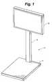
- FIG. 1shows a front perspective view of a display and stand in accordance with an embodiment of the invention.
- FIG. 2shows a top plan view of a lift system in a first position in accordance with an embodiment of the invention.
- FIG. 3shows the lift system of FIG. 2 in a second position in accordance with an embodiment of the invention.
- FIG. 4shows a top plan view of a lift system in accordance with an embodiment of the invention.
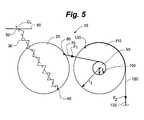
- FIG. 5shows the lift system of FIG. 4 in a second position in accordance with an embodiment of the invention.
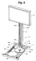
- FIG. 6shows a front perspective view of a display and stand with a lift system in accordance with an embodiment of the invention.
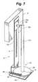
- FIG. 7shows a rear perspective view of a display and stand with a lift system in accordance with another embodiment of the invention.
- lift system systems and methods useful for lifting an objectsuch as a flat panel display of the type commonly used as television sets and computer screens.
- Various embodiments of the lift systems discussed hereinhave several advantages. For example, these lift systems are settable versus adjustable. This refers to the property of the system that allows it to position an object at any suitable location with one hand rather than set into a predefined position using two hands.
- these systemsare easily maneuverable. For example, lift systems in accordance with embodiments of the invention are moveable using less than a predefined percentage of the object weight. For example, in some embodiments, the lift system and object can be maneuvered using a force equal to 10% or less of the weight of the object itself.
- lift systems in accordance with embodiments of the inventionare infinitely adjustable along the range of travel rather than locked into position at a series of predefined points. All of these properties are provided in a lift system that is low cost to produce and highly reliable.
- some embodiments of the inventioninclude a stand 2 having a base 4 and a vertical member 6 .
- one or more displays 8e.g., flat panel displays, such as liquid crystal displays (LCDs) or plasma displays
- LCDsliquid crystal displays
- plasma displaysmay be coupled the stand 2 .
- the stand 2may house a lift system to provide for the display 8 to be set at any point along a range of travel relative to the base in an easily maneuverable manner.
- the lift systemmay be housed in a cavity defined by the base 4 of the stand 2 .
- the lift system 10includes a first pulley 20 having an axis of rotation A and a biasing member 30 (e.g., a spring, such as an extension spring) with a first portion 40 (e.g., a first end) operatively coupled to the first pulley 20 .
- a biasing member 30e.g., a spring, such as an extension spring
- first portion 40e.g., a first end
- “Operatively coupled,” as used herein,can include, for example, clamps, screws, adhesives and/or integral formation for a direct type coupling, or the use of various spacers, trucks and/or brackets for a more indirect type coupling.
- the biasing memberis coupled proximate an outer circumference of the pulley.
- the biasing member 30may have a second portion 50 operatively coupled to a support 60 (e.g., a fixed member coupled to the stand, a housing fixed member, or wall). In some embodiments, the biasing member is free to pivot about its connection to the pulley and the support. Also shown in the embodiment of FIGS. 2 and 3 , the lift system 10 includes a first tension member 70 (e.g., a cable or rope) having a first portion 80 operatively coupled to the first pulley 20 . Such a lift system 10 is useful for providing a constant force to the first tension member 70 during a defined angle DA rotation of the first pulley 20 . As will be understood by those skilled in the art, “constant force” or “generally constant force” means an effectively constant force, such as plus or minus 10% or less (e.g., 5% or less) of a purely constant force output.
- such a constant moment outputcan be achieved until about 10 degrees to about 20 degrees before D 1 becomes zero.
- the first tension member 70can be used to apply a rotating force to the first pulley.
- the force F 1 experienced by the first tension memberwill be generally constant throughout the first pulley movement through the defined angle.
- the first radiuswill have a maximum when the biasing member has a first length and a minimum when the biasing member has a second length, the second length being the maximum biasing member length.
- the biasing memberwill have a length, and the length of the biasing member continuously increases as the first radius continuously decreases during the defined angle of rotation of the first pulley.
- the defined angleis less than about 180 degrees. In other embodiments, the defined angle is less than about 135 degrees. In yet other embodiments, the defined angle is less than about 90 degrees. In some embodiments, the defined angle is less than 45 degrees. In yet other embodiments, the defined angle is less than about 30 degrees. In some embodiments, the defined angle is about 15 degrees.
- the lift system 10in configured to increase the range of travel of a lifted object, such as a display, compared to what is provided by the defined angle DA.
- the lift system 10can include a second pulley 90 with a radius r 2 operatively coupled to the first pulley 20 via a second portion 100 of the first tension member 70 .
- the second pulley 90is operatively coupled to a third pulley 110 having a radius r 3 .
- the second pulley and third pulleyare integrally formed with one another.
- the second pulley and third pulleycan have coaxial axes of rotation.
- the second pulley and third pulleyare vertically offset from one another about a common axis of rotation.
- the radius r 2 of the second pulley 90can be less than the radius r 3 of the third pulley 110 .
- the third pulley radiusis at least about twice the length of the second pulley radius.
- the third pulley radius divided by the second pulley radiusdefines a ratio, the ratio being greater than about two (e.g., greater than about 3).
- the third pulley 110has a second tension member 120 with a first portion 130 operatively coupled thereto.
- the force F 1 described abovemay be transferred to the second pulley 90 via first tension member 70 .
- the third pulley 110will rotate a full turn too, thereby magnifying the range of motion of a second portion 132 (and any object associated therewith) of the second tension member 120 as the first pulley 20 moves through the defined angle.
- force F 1is a generally constant force through the defined angle
- force F 2will also be generally constant through this angle.
- an object, such as a displayassociated with the second portion of the second tension member can provide a balancing force generally equal to F 1 .
- Such a displaywill be settable, easily maneuverable, and infinitely adjustable along the range of travel.
- FIGS. 2-5are referred to as a “top plan” views, it should be noted that designation is only for purposes of discussion, and that embodiments of the lift system may be orientated in any suitable fashion, including vertical and horizontal. Further, embodiments of the lift system may also be configured to lift an object in any direction, including vertical and horizontal.
- FIG. 6shows an embodiment of a lift system 10 in a stand 2 supporting a display 8 .
- the lift system 10is housed in a cavity in the base 4 of the stand 2 .
- the vertical portion 6 of the stand 2includes an outer member 140 fixed to the base and an inner member 150 fixed to the display 8 .
- the outer memberwill be fixed to the display and the inner member will be fixed to the base.
- the inner and outer membersare in sliding or rolling engagement with each other to allow the display 8 to be set at any height relative to the base within a defined range of travel.
- one or more pulleys 160may be provided to route the second tension member 120 from the third pulley 110 to the vertical member 6 .
- the third pulley 110As the display 8 is lowered relative to the base it allows the third pulley 110 to rotate, in this example, in a clockwise direction.
- the second pulley 90will also rotate in a clockwise direction.
- the first pulley 20will rotate in a clockwise direction and the biasing member length L will decrease (thereby changing the biasing member force) while D 1 increases to provide a continuously counterbalancing force to the display as it is moved downward through its range of motion and to provide the proper counterbalancing force to hold the display at its new position.
- Raising the displaycauses the first, second, and third pulleys to rotate in a counterclockwise direction and the biasing member length L to expand and D 1 to decrease to provide a continuously counterbalancing force to the display as it is moved upward through its range of motion and in its new desired position.
- FIG. 7Another embodiment of the invention is shown in FIG. 7 .
- first pulley 20 and biasing member 30are housed in the base 4 of the stand 2 .
- the biasing member length L (and associated biasing member force) and D 1cooperatively change together as the display is moved through its range of motion as discussed above.
- a contact member 170e.g., cam member
- the contact memberhas a longitudinal axis that coincides with the axis of rotation of the first pulley.
- an engagement member 190e.g., cam engagement member
- useful for engaging the contact surfacecan be coupled with the display.
- the contact surfacetakes the form of a helical groove. In other embodiments, the contact surface takes the form of a generally serpentine groove in the contact member to provide a camming surface. Such embodiments are useful for more closely approximating a pure constant force output.
- the engagement memberincludes a rigid protrusion that rides within the groove. In the embodiment shown, as the display is moved downwardly relative to the base the engagement member rides within the groove and interacts with the contact surface. The interaction causes the contact member and the first pulley to move in a counterclockwise direction.
- the biasing member length Lwill increase while D 1 decreases to provide a continuously counterbalancing force to the display and it is moved downward through its range of motion and to provide the proper counterbalancing force to hold the display at its new position.
- Raising the displaycauses the cam member to rotate in a clockwise direction and the biasing member length L to decrease and D 1 to increase to provide a continuously counterbalancing force to the display as it is moved upward through its range of motion and in its new desired position.
- Embodiments of the inventionalso include methods of making and using the various embodiments of lift systems described above.
- a lift system as described abovecan be provided.
- the usercan manually engage the display and apply a force in the vertical direction.
- the third pulley 110will rotate.
- the second pulley 90 attached to the first tension member 70will rotate in the same direction.
- rotation of a contact memberwill cause the first pulley to rotate.
- the first tension member 70will cause the first pulley 20 to rotate through its defined angle, causing an extension of the biasing member.
- the resistance force experienced by the user during the repositioningis relatively constant.
- the forceis counterbalanced, the user will be able to reposition the display using a force equal to a fraction of the weight of the display.
Landscapes
- Engineering & Computer Science (AREA)
- General Engineering & Computer Science (AREA)
- Mechanical Engineering (AREA)
- Devices For Indicating Variable Information By Combining Individual Elements (AREA)
Abstract
Description
Claims (18)
Priority Applications (1)
| Application Number | Priority Date | Filing Date | Title |
|---|---|---|---|
| US11/828,866US8228668B2 (en) | 2006-07-26 | 2007-07-26 | Balanced moment lift system and method |
Applications Claiming Priority (2)
| Application Number | Priority Date | Filing Date | Title |
|---|---|---|---|
| US83350306P | 2006-07-26 | 2006-07-26 | |
| US11/828,866US8228668B2 (en) | 2006-07-26 | 2007-07-26 | Balanced moment lift system and method |
Publications (2)
| Publication Number | Publication Date |
|---|---|
| US20080026892A1 US20080026892A1 (en) | 2008-01-31 |
| US8228668B2true US8228668B2 (en) | 2012-07-24 |
Family
ID=38987021
Family Applications (1)
| Application Number | Title | Priority Date | Filing Date |
|---|---|---|---|
| US11/828,866Active2031-02-22US8228668B2 (en) | 2006-07-26 | 2007-07-26 | Balanced moment lift system and method |
Country Status (1)
| Country | Link |
|---|---|
| US (1) | US8228668B2 (en) |
Cited By (24)
| Publication number | Priority date | Publication date | Assignee | Title |
|---|---|---|---|---|
| US20120019990A1 (en)* | 2009-12-07 | 2012-01-26 | Ergotron, Inc. | Brake stand systems |
| US20130112818A1 (en)* | 2011-11-09 | 2013-05-09 | Jarllytec Co., Ltd. | Screen supporter |
| US20140077050A1 (en)* | 2012-09-17 | 2014-03-20 | Ming-Hsien Huang | Lifting device |
| USD722794S1 (en)* | 2012-11-18 | 2015-02-24 | Kevin Luong | Retail multimedia product and presentation display |
| USD734965S1 (en)* | 2012-09-19 | 2015-07-28 | Apple Inc. | Display structure |
| US20150228149A1 (en)* | 2001-09-28 | 2015-08-13 | Igt | Wide screen gaming apparatus |
| US9277812B2 (en) | 2010-07-08 | 2016-03-08 | Southco, Inc. | Display support with first and second arms and mechanism for maintaining constant orientation of the plane bisecting the range of rotation of the second arm relative to a support base |
| USD758106S1 (en)* | 2011-06-01 | 2016-06-07 | Apple Inc. | Display structure |
| USD842930S1 (en) | 2016-09-22 | 2019-03-12 | Igt | Gaming device cabinet |
| USD843468S1 (en) | 2016-09-22 | 2019-03-19 | Igt | Gaming device cabinet |
| USD843467S1 (en) | 2016-09-22 | 2019-03-19 | Igt | Gaming device cabinet |
| USD858153S1 (en) | 2017-05-05 | 2019-09-03 | Apple Inc. | Retail display |
| USD867036S1 (en) | 2018-07-09 | 2019-11-19 | Apple Inc. | Retail fixture |
| USD867035S1 (en) | 2018-07-10 | 2019-11-19 | Apple Inc. | Retail fixture |
| USD885805S1 (en) | 2018-07-10 | 2020-06-02 | Apple Inc. | Retail fixture |
| US10845000B2 (en) | 2016-10-21 | 2020-11-24 | Colebrook Bosson Saunders (Products) Limited | Display support system |
| US11131423B2 (en) | 2016-03-07 | 2021-09-28 | Southco, Inc. | Display support arm assembly for mounting a display |
| USD935813S1 (en) | 2019-11-15 | 2021-11-16 | Apple Inc. | Retail fixture |
| US20220039276A1 (en)* | 2020-08-03 | 2022-02-03 | Giga-Byte Technology Co., Ltd. | Display stand holder and display apparatus thereof |
| USD946324S1 (en) | 2018-07-31 | 2022-03-22 | Apple Inc. | Retail fixture group |
| US20230024561A1 (en)* | 2021-07-21 | 2023-01-26 | Lg Electronics Inc. | Display device |
| US11904965B1 (en) | 2021-04-06 | 2024-02-20 | Ronald La Porte | Bicycle brake lock |
| USD1058678S1 (en) | 2022-12-14 | 2025-01-21 | Igt | Gaming machine cabinet |
| USD1097657S1 (en) | 2024-08-26 | 2025-10-14 | Apple Inc. | Retail fixture |
Families Citing this family (25)
| Publication number | Priority date | Publication date | Assignee | Title |
|---|---|---|---|---|
| TWI367670B (en)* | 2008-03-11 | 2012-07-01 | Qisda Corp | Height adjustable holding apparatus |
| US8905496B2 (en)* | 2008-12-11 | 2014-12-09 | Rubbermaid Incorporated | Wall work station |
| WO2011060223A1 (en)* | 2009-11-13 | 2011-05-19 | Ergotron, Inc. | Vertical spring lift systems |
| US20110235249A1 (en)* | 2010-01-29 | 2011-09-29 | Rubbermaid Incorporated | Work surface articulation |
| US8616136B2 (en)* | 2010-01-29 | 2013-12-31 | Rubbermaid Incorporated | Keyboard tray tilt |
| US8567735B2 (en)* | 2010-01-29 | 2013-10-29 | Rubbermaid Incorporated | Work station with height adjustment lock |
| US8826831B2 (en) | 2010-07-30 | 2014-09-09 | Ergotron, Inc. | Display positioning apparatus and method |
| US12022941B2 (en) | 2010-07-30 | 2024-07-02 | Ergotron, Inc. | Display positioning apparatus and method |
| US8967560B2 (en) | 2010-07-30 | 2015-03-03 | Ergotron, Inc. | Cam balance mechanism systems and methods |
| CA2805389C (en) | 2010-07-30 | 2019-02-26 | Ergotron, Inc. | Display positioning apparatus and method |
| US9188275B2 (en) | 2010-07-30 | 2015-11-17 | Ergotron, Inc. | Edge mount positioning apparatus, system, and method |
| CA2826701C (en) | 2011-02-11 | 2020-03-24 | Ergotron, Inc. | Bifocal display positioning apparatus and method |
| US8677911B2 (en) | 2011-02-18 | 2014-03-25 | Rubbermaid Incorporated | Technology cart |
| US8662605B2 (en) | 2011-02-18 | 2014-03-04 | Rubbermaid Incorporated | Mobile technology cabinet |
| TWI425834B (en)* | 2011-08-08 | 2014-02-01 | Qisda Corp | Support frame and monitor using the same |
| CN102359702B (en)* | 2011-09-02 | 2013-01-02 | 苏州佳世达电通有限公司 | Support frame and display using same |
| EP2831486B1 (en)* | 2012-03-30 | 2018-05-23 | Ergotron, Inc. | Counterbalancing lift mechanisms and methods |
| CN102963852B (en)* | 2012-08-24 | 2015-05-13 | 深圳市海亚科技发展有限公司 | Gravity balance mechanism |
| EP2914180B1 (en)* | 2012-10-31 | 2018-03-07 | Brainlab AG | Positioning device for a medical field generator |
| CN103901944B (en)* | 2012-12-24 | 2017-11-28 | 联想(北京)有限公司 | A kind of method and electronic equipment for adjusting position of centre of gravity |
| US9933106B2 (en) | 2013-03-14 | 2018-04-03 | Capsa Solutions, Llc | Height adjustable support |
| TWM467080U (en)* | 2013-08-20 | 2013-12-01 | Syncmold Entpr Corp | Monitor stand lifting mechanism |
| USD769881S1 (en) | 2014-08-18 | 2016-10-25 | Humanscale Corporation | Height adjustable workstation |
| DE102015120809B9 (en)* | 2015-12-01 | 2019-01-24 | Hermann Maderbacher | Device for holding a screen |
| USD849456S1 (en) | 2017-04-11 | 2019-05-28 | Humanscale Corporation | Workstation |
Citations (124)
| Publication number | Priority date | Publication date | Assignee | Title |
|---|---|---|---|---|
| US1222915A (en) | 1915-08-13 | 1917-04-17 | Frank Ridlon Company | Electric-light stand. |
| US1965973A (en) | 1933-07-11 | 1934-07-10 | Brown Frank Elwood | Broom hanger |
| US2010214A (en) | 1933-07-03 | 1935-08-06 | Braun Karl | Compensating device for sash windows and the like |
| US2168209A (en)* | 1937-07-16 | 1939-08-01 | Kelley Koett Mfg Company Inc | Spring counterbalance |
| US2178122A (en) | 1937-01-14 | 1939-10-31 | Deckel Friedrich | Power equalizing device |
| US2471998A (en) | 1943-03-22 | 1949-05-31 | Hartford Nat Bank & Trust Co | Column-stand for supporting apparatus vertically movable along the column, particularly x-ray apparatus |
| US2480865A (en) | 1943-08-19 | 1949-09-06 | Anders R Lofstrand | Leverage pulley |
| US2506228A (en) | 1943-08-19 | 1950-05-02 | Sr Anders R Lofstrand | Counterbalance for glassware washing machines |
| US2657925A (en)* | 1946-03-27 | 1953-11-03 | Crow Rector | Closure, operating, and controlling device |
| US2876362A (en) | 1956-09-10 | 1959-03-03 | Picker X Ray Corp Waite Mfg | Compensating cam and spring balance for x-ray devices |
| US2924411A (en) | 1955-05-19 | 1960-02-09 | Grinnell Corp | Counterbalancing mechanism |
| DE1091279B (en) | 1958-09-12 | 1960-10-20 | Picker X Ray Corp Waite Mfg Di | Height-adjustable ceiling suspension with weight compensation |
| US3113793A (en) | 1960-08-08 | 1963-12-10 | Richard J Harwood | Positioning means for seat structures and the like |
| DE1171222B (en) | 1958-10-30 | 1964-05-27 | Elin Union Ag | Cam gear to compensate for a constant load over your excursion |
| US3269035A (en)* | 1963-11-26 | 1966-08-30 | A Varren Dr Ing | Spring balanced adjustable blackboard |
| US3534935A (en) | 1967-04-04 | 1970-10-20 | Ronald Leonard Gunn | Sliding display or storage units and catch mechanisms therefor |
| US3543282A (en) | 1967-04-11 | 1970-11-24 | Lucien Emile | Drawing board |
| US3575368A (en) | 1969-01-27 | 1971-04-20 | Westinghouse Electric Corp | Vertically adjustable counterbalancing x-ray tube head suspension support apparatus |
| US3675597A (en) | 1969-05-20 | 1972-07-11 | Trygve R Oddsen | Table top support |
| US3767181A (en) | 1970-07-07 | 1973-10-23 | Burgt Gerrit V D | Spring system |
| DE1611809C3 (en) | 1967-03-17 | 1974-03-07 | Andre Besancon Bruneau (Frankreich | Weight compensation device for a height-adjustable drawing table |
| US3862734A (en) | 1973-05-17 | 1975-01-28 | Berthold Ag H | Instrument head mounting |
| US3890907A (en) | 1973-10-24 | 1975-06-24 | Joerns Furniture Co | Vertically adjustable overbed table |
| USRE28767E (en) | 1971-10-11 | 1976-04-13 | Franz Kuhlmann Kg | Drawing table |
| US3976016A (en) | 1974-12-23 | 1976-08-24 | Rca Corporation | Overbed table with locking mechanism |
| US4215776A (en) | 1977-11-10 | 1980-08-05 | Joseph M. Stofan | Belt conveyor idler |
| US4351245A (en) | 1980-09-04 | 1982-09-28 | Laporte Joseph L | Counterweight system |
| US4357249A (en) | 1980-09-11 | 1982-11-02 | Arguto, Inc. | Self-lubricating bearing and the like, and method of making same |
| US4387468A (en) | 1981-10-09 | 1983-06-07 | Techny Industries, Inc. | Mobile X-ray apparatus |
| US4387876A (en) | 1979-05-05 | 1983-06-14 | Advanced Products Beer-Sheva Ltd. | Constant force generator mechanism and adjustable seat constructed therewith |
| US4389228A (en) | 1981-08-26 | 1983-06-21 | Albany International Corp. | Constant tensioning device |
| US4427243A (en) | 1981-07-28 | 1984-01-24 | Decision Data Computer Corporation | Display station tilt mechanism |
| US4494720A (en) | 1981-12-14 | 1985-01-22 | Digital Equipment Corporation | Tilt swivel base |
| DE3406669A1 (en) | 1984-02-24 | 1985-08-29 | Peter 7022 Leinfelden-Echterdingen Heckmann | Weight-compensating device for vertically adjustable furniture, preferably having only one support leg |
| GB2154442A (en) | 1984-02-21 | 1985-09-11 | Reginald John Spratling | Support unit |
| EP0183938A1 (en) | 1984-12-07 | 1986-06-11 | International Business Machines Corporation | Counterbalanced, height adjustable load carrying apparatus |
| US4605189A (en) | 1983-09-07 | 1986-08-12 | Alpia S.A. | Anti-fail device for locking a drawing-board pillar against motion |
| US4616218A (en) | 1983-01-03 | 1986-10-07 | International Business Machines Corporation | Adjustable CRT display |
| EP0202533A2 (en) | 1985-05-17 | 1986-11-26 | Bausch & Lomb Incorporated | Counterbalancing apparatus for use in an optical instrument |
| US4690362A (en) | 1984-06-26 | 1987-09-01 | Tangberg Data A/S | Adjustable stand for a visual display unit |
| US4691886A (en) | 1985-04-18 | 1987-09-08 | Texas Instruments Incorporated | Adjustable display stand |
| DE3610612A1 (en) | 1986-03-29 | 1987-10-01 | Hados Moebelfabrik Doll Gmbh & | Weight counterbalance device |
| US4697977A (en) | 1983-06-15 | 1987-10-06 | Litton Systems, Inc. | Safety brake for vertical lift |
| US4706920A (en) | 1984-02-29 | 1987-11-17 | Nhk Spring Co. Limited | Television stand having a tilt mechanism |
| US4751884A (en) | 1985-10-09 | 1988-06-21 | Hauseman, Inc. | Height adjustable work top |
| US4760622A (en)* | 1986-07-31 | 1988-08-02 | Schlegel Corporation | Compound winding apparatus and counterbalance systems |
| US4768762A (en)* | 1985-05-15 | 1988-09-06 | Lund Kurt O | Means and method to counterbalance the weight of a body |
| US4836478A (en) | 1987-10-15 | 1989-06-06 | Ergotron, Inc. | Suspension system for personal computers and monitors |
| US4856740A (en) | 1988-03-07 | 1989-08-15 | Macleod Edwin A | Multi-purpose indoor/outdoor refuse bag support |
| US4914780A (en) | 1988-08-02 | 1990-04-10 | Schlegel Corporation | Compound counterbalance and winding systems with zero torque spirals |
| US4920381A (en) | 1989-01-03 | 1990-04-24 | Eastman Kodak Company | Toner container lift mechanism |
| US4922836A (en) | 1988-12-01 | 1990-05-08 | Thill, Inc. | Lead screw support mechanism for an overbed table |
| US4953256A (en) | 1989-02-06 | 1990-09-04 | Raytheon Company | Counterbalance mechanism |
| US4953748A (en) | 1988-08-23 | 1990-09-04 | Diebold, Incorporated | Force modifying device |
| US4964152A (en) | 1988-10-13 | 1990-10-16 | Siemens Aktiengesellschaft | Portable x-ray diagnostics apparatus having a height-adjustable column |
| US4964221A (en) | 1988-07-07 | 1990-10-23 | Carl-Zeiss-Stiftung, Heidenheim/Brenz | Counterbalanced coordinate-measuring instrument |
| US5101735A (en)* | 1990-08-27 | 1992-04-07 | Williams Matti I | Constant tension apparatus and method with eccentric cam to regulate tension |
| US5143333A (en) | 1989-08-25 | 1992-09-01 | Siemens Aktiengesellschaft | Weight counterbalance means |
| US5160104A (en) | 1988-10-20 | 1992-11-03 | Sher Joseph M | Vertically adjustable holder |
| US5229584A (en) | 1991-03-06 | 1993-07-20 | Missions Marketing, Inc. | Encounter billing system |
| US5246191A (en) | 1991-10-17 | 1993-09-21 | James Moss | Cradle assembly for a moveable arm support system |
| US5305996A (en) | 1991-11-13 | 1994-04-26 | Fujitsu Limited | Paper hopper |
| US5311827A (en) | 1992-06-18 | 1994-05-17 | Greene H Peter | Load compensator for spring counter-weighting mechanism |
| US5400721A (en)* | 1992-06-18 | 1995-03-28 | Greene; H. Peter | Load compensator for spring counter-weighting mechanism |
| US5487525A (en) | 1991-10-18 | 1996-01-30 | Drabczyk; Matthew P. | Adjustable keyboard holder for workstations |
| US5520361A (en) | 1993-04-20 | 1996-05-28 | Inkel Corporation | Monitor tilting device |
| US5549264A (en) | 1994-07-01 | 1996-08-27 | Baxter International Inc. | Support pole lift mechanism |
| US5589849A (en) | 1989-07-03 | 1996-12-31 | Ditzik; Richard J. | Display monitor position adjustment apparatus |
| US5626323A (en) | 1995-05-31 | 1997-05-06 | Nova Solutions, Inc. | Adjustable keyboard holder |
| US5668570A (en) | 1993-06-29 | 1997-09-16 | Ditzik; Richard J. | Desktop computer with adjustable flat panel screen |
| US5718406A (en) | 1996-01-11 | 1998-02-17 | Long; Dennis L. | Counterbalance apparatus |
| US5722513A (en) | 1995-06-20 | 1998-03-03 | Pentalift Equipment Corporation | Scissor lift |
| DE19635236C1 (en) | 1996-08-30 | 1998-03-12 | Siemens Ag | Counterweight device especially for medical X-ray equipment |
| US5738316A (en) | 1995-04-03 | 1998-04-14 | Ergotron, Inc. | Vertical work center |
| US5743503A (en) | 1996-03-08 | 1998-04-28 | Ergotron, Inc. | Computer suspension system |
| US5836562A (en) | 1996-08-16 | 1998-11-17 | Fellowes Manufacturing Company | Mounting device for an apparatus for supporting a keyboard |
| US5842672A (en) | 1996-06-07 | 1998-12-01 | Ergotron, Inc. | Mounting system for flat panel display, keyboard and stand |
| US5860370A (en) | 1997-06-02 | 1999-01-19 | Poniecki; Andy | Universally adjustable, portable shelving unit |
| US5876008A (en) | 1995-01-17 | 1999-03-02 | Ergotron, Inc. | Suspension system for video monitor or other equipment |
| US5881984A (en) | 1997-06-20 | 1999-03-16 | Lin; Chin-Chih | Dimensional adjusting device for computer keyboards racks |
| US5902201A (en) | 1996-03-14 | 1999-05-11 | U.S. Philips Corporation | Positioning device and component placement machine including the positioning device |
| US5904328A (en) | 1997-06-23 | 1999-05-18 | Stb Systems, Inc. | Articulating computer monitor |
| DE29908098U1 (en) | 1999-01-15 | 1999-07-22 | Ctx Opto-Electronics Corp., Hsinchu | Lifting device for a liquid crystal display device |
| US5931549A (en) | 1997-08-25 | 1999-08-03 | Lindberg; Paul E. | Computer workstation with movable platform |
| US6012693A (en) | 1998-02-19 | 2000-01-11 | Ergotron, Inc. | Multi-function display mounting system |
| GB2338894A (en) | 1998-06-18 | 2000-01-12 | Grorud Eng Ltd | Support, particularly for flat-panel monitors |
| US6026755A (en) | 1996-01-11 | 2000-02-22 | Long; Dennis L. | Counterbalance apparatus |
| GB2346071A (en) | 1999-01-27 | 2000-08-02 | Andrew John Nelson Wills | An adjustable support for an apparatus |
| EP1052472A2 (en) | 1999-05-11 | 2000-11-15 | Mitutoyo Corporation | Constant pressure mechanism of probe |
| US6189849B1 (en) | 1998-05-06 | 2001-02-20 | Ergotron, Inc. | Lift system |
| US6229584B1 (en) | 1999-11-15 | 2001-05-08 | Compal Electronics, Inc. | Liquid crystal display monitor having a monitor stand with a replaceable housing part |
| US6227518B1 (en) | 1999-09-08 | 2001-05-08 | Compal Electronics, Inc. | Pivot base for a computer monitor |
| US6282264B1 (en) | 1999-10-06 | 2001-08-28 | Hologic, Inc. | Digital flat panel x-ray detector positioning in diagnostic radiology |
| US6283462B1 (en) | 1999-11-02 | 2001-09-04 | Raymond L. Emmert | Helical spring tension adjuster |
| US6286794B1 (en) | 1999-06-14 | 2001-09-11 | Bradley Harbin | Ergonomic computer mounting device permitting extensive vertical, horizontal and angular ranges of motion |
| US6378829B1 (en) | 1997-05-23 | 2002-04-30 | Straeter Fritz | Articulated bracket for office equipment |
| WO2002044609A1 (en) | 2000-11-28 | 2002-06-06 | Constant Force Technology, Llc | Methods and apparatus for generating force and torque |
| US6411271B1 (en) | 1998-03-18 | 2002-06-25 | Samsung Electronics Co., Ltd. | Liquid crystal display |
| US6418010B1 (en)* | 2000-08-11 | 2002-07-09 | Gateway, Inc. | Convertible flat panel display hanging support |
| US20020100851A1 (en) | 2000-10-19 | 2002-08-01 | Heinz Abramowsky | Pivot mounting assembly |
| US6504707B2 (en) | 2000-06-14 | 2003-01-07 | International Business Machines Corporation | Portable computer |
| JP2003295161A (en) | 2002-04-05 | 2003-10-15 | Kato Electrical Mach Co Ltd | Stand for liquid crystal display device |
| US20040011932A1 (en) | 2002-06-07 | 2004-01-22 | Simon Duff | Stand for flat panel display |
| US20040035243A1 (en) | 2002-05-22 | 2004-02-26 | Duval Eugene F. | Counter balance system and method with one or more mechanical arms |
| US20040035989A1 (en) | 2002-08-21 | 2004-02-26 | Sweere Harry C. | Stand |
| US6702238B1 (en) | 2003-03-28 | 2004-03-09 | Top Victory Electronics Co., Ltd. | Adjustable supporting device for a display panel |
| US6712321B1 (en) | 2003-05-21 | 2004-03-30 | Compal Electronics, Inc. | Adjustable supporting device for a display panel |
| US20040084585A1 (en) | 2001-12-13 | 2004-05-06 | Atsushi Watanabe | Direction regulator of display |
| US20040118984A1 (en) | 2002-09-27 | 2004-06-24 | Samsung Electronics Co., Ltd. | Display apparatus |
| US6783105B2 (en) | 2001-06-20 | 2004-08-31 | Innovative Office Products, Inc. | Adjustable display arm for computer components |
| US6796537B1 (en) | 2004-01-13 | 2004-09-28 | Pei-Ching Lin | Lifting base for a LCD monitor |
| US6819550B2 (en)* | 2001-11-08 | 2004-11-16 | Apple Computer, Inc. | Computer controlled display device |
| US20040250635A1 (en) | 2003-05-20 | 2004-12-16 | Sweere Harry C. | Lift mechanism based on torque equalization principles |
| US20050034547A1 (en) | 2003-08-01 | 2005-02-17 | Sweere Harry C. | Mechanisms based on torque equalization principles |
| US20050139734A1 (en) | 2000-11-28 | 2005-06-30 | Constant Force Technology, Llc | Monitor support system |
| US7063024B2 (en) | 2003-07-03 | 2006-06-20 | Wright Line, Llc | Computer monitor lift and storage mechanism |
| US20060185563A1 (en) | 2004-07-30 | 2006-08-24 | Sweere Harry C | Lift mechanism systems and methods |
| US7104203B2 (en) | 2004-06-16 | 2006-09-12 | Chiu-Hsiang Lo | Height adjustable device for a retractable tube assembly |
| US20060219849A1 (en)* | 2005-04-04 | 2006-10-05 | Fulfil Tech. Co., Ltd. | Height-adjustable support for a display device |
| US7168665B2 (en)* | 2002-07-06 | 2007-01-30 | Samsung Electronics Co., Ltd. | Display apparatus |
| US20080099637A1 (en)* | 2006-10-19 | 2008-05-01 | Chih-Tang Pai | Stepless Adjustable Supporting Device |
| US7621490B2 (en)* | 2007-03-02 | 2009-11-24 | Qisda Corporation | Height adjustable holding apparatus |
| US7789354B2 (en)* | 2007-12-27 | 2010-09-07 | Hong Fu Jin Precision Industry (Shenzhen) Co., Ltd. | Adjustable support mechanism for display devices and support stand utilizing the same |
| US20110155867A1 (en)* | 2009-12-30 | 2011-06-30 | Krueger International, Inc. | Monitor lift mechanism |
- 2007
- 2007-07-26USUS11/828,866patent/US8228668B2/enactiveActive
Patent Citations (140)
| Publication number | Priority date | Publication date | Assignee | Title |
|---|---|---|---|---|
| US1222915A (en) | 1915-08-13 | 1917-04-17 | Frank Ridlon Company | Electric-light stand. |
| US2010214A (en) | 1933-07-03 | 1935-08-06 | Braun Karl | Compensating device for sash windows and the like |
| US1965973A (en) | 1933-07-11 | 1934-07-10 | Brown Frank Elwood | Broom hanger |
| US2178122A (en) | 1937-01-14 | 1939-10-31 | Deckel Friedrich | Power equalizing device |
| US2168209A (en)* | 1937-07-16 | 1939-08-01 | Kelley Koett Mfg Company Inc | Spring counterbalance |
| US2471998A (en) | 1943-03-22 | 1949-05-31 | Hartford Nat Bank & Trust Co | Column-stand for supporting apparatus vertically movable along the column, particularly x-ray apparatus |
| US2480865A (en) | 1943-08-19 | 1949-09-06 | Anders R Lofstrand | Leverage pulley |
| US2506228A (en) | 1943-08-19 | 1950-05-02 | Sr Anders R Lofstrand | Counterbalance for glassware washing machines |
| US2657925A (en)* | 1946-03-27 | 1953-11-03 | Crow Rector | Closure, operating, and controlling device |
| US2924411A (en) | 1955-05-19 | 1960-02-09 | Grinnell Corp | Counterbalancing mechanism |
| US2876362A (en) | 1956-09-10 | 1959-03-03 | Picker X Ray Corp Waite Mfg | Compensating cam and spring balance for x-ray devices |
| DE1091279B (en) | 1958-09-12 | 1960-10-20 | Picker X Ray Corp Waite Mfg Di | Height-adjustable ceiling suspension with weight compensation |
| DE1171222B (en) | 1958-10-30 | 1964-05-27 | Elin Union Ag | Cam gear to compensate for a constant load over your excursion |
| US3113793A (en) | 1960-08-08 | 1963-12-10 | Richard J Harwood | Positioning means for seat structures and the like |
| US3269035A (en)* | 1963-11-26 | 1966-08-30 | A Varren Dr Ing | Spring balanced adjustable blackboard |
| DE1611809C3 (en) | 1967-03-17 | 1974-03-07 | Andre Besancon Bruneau (Frankreich | Weight compensation device for a height-adjustable drawing table |
| US3534935A (en) | 1967-04-04 | 1970-10-20 | Ronald Leonard Gunn | Sliding display or storage units and catch mechanisms therefor |
| US3543282A (en) | 1967-04-11 | 1970-11-24 | Lucien Emile | Drawing board |
| US3575368A (en) | 1969-01-27 | 1971-04-20 | Westinghouse Electric Corp | Vertically adjustable counterbalancing x-ray tube head suspension support apparatus |
| FR2037056B1 (en) | 1969-01-27 | 1975-02-21 | Westinghouse Electric Corp | |
| US3675597A (en) | 1969-05-20 | 1972-07-11 | Trygve R Oddsen | Table top support |
| US3767181A (en) | 1970-07-07 | 1973-10-23 | Burgt Gerrit V D | Spring system |
| USRE28767E (en) | 1971-10-11 | 1976-04-13 | Franz Kuhlmann Kg | Drawing table |
| US3862734A (en) | 1973-05-17 | 1975-01-28 | Berthold Ag H | Instrument head mounting |
| US3890907A (en) | 1973-10-24 | 1975-06-24 | Joerns Furniture Co | Vertically adjustable overbed table |
| US3976016A (en) | 1974-12-23 | 1976-08-24 | Rca Corporation | Overbed table with locking mechanism |
| US4215776A (en) | 1977-11-10 | 1980-08-05 | Joseph M. Stofan | Belt conveyor idler |
| US4387876A (en) | 1979-05-05 | 1983-06-14 | Advanced Products Beer-Sheva Ltd. | Constant force generator mechanism and adjustable seat constructed therewith |
| US4351245A (en) | 1980-09-04 | 1982-09-28 | Laporte Joseph L | Counterweight system |
| US4357249A (en) | 1980-09-11 | 1982-11-02 | Arguto, Inc. | Self-lubricating bearing and the like, and method of making same |
| US4427243A (en) | 1981-07-28 | 1984-01-24 | Decision Data Computer Corporation | Display station tilt mechanism |
| US4389228A (en) | 1981-08-26 | 1983-06-21 | Albany International Corp. | Constant tensioning device |
| US4387468A (en) | 1981-10-09 | 1983-06-07 | Techny Industries, Inc. | Mobile X-ray apparatus |
| US4494720A (en) | 1981-12-14 | 1985-01-22 | Digital Equipment Corporation | Tilt swivel base |
| US4616218A (en) | 1983-01-03 | 1986-10-07 | International Business Machines Corporation | Adjustable CRT display |
| US4697977A (en) | 1983-06-15 | 1987-10-06 | Litton Systems, Inc. | Safety brake for vertical lift |
| US4605189A (en) | 1983-09-07 | 1986-08-12 | Alpia S.A. | Anti-fail device for locking a drawing-board pillar against motion |
| GB2154442A (en) | 1984-02-21 | 1985-09-11 | Reginald John Spratling | Support unit |
| DE3406669A1 (en) | 1984-02-24 | 1985-08-29 | Peter 7022 Leinfelden-Echterdingen Heckmann | Weight-compensating device for vertically adjustable furniture, preferably having only one support leg |
| US4706920A (en) | 1984-02-29 | 1987-11-17 | Nhk Spring Co. Limited | Television stand having a tilt mechanism |
| US4690362A (en) | 1984-06-26 | 1987-09-01 | Tangberg Data A/S | Adjustable stand for a visual display unit |
| EP0183938A1 (en) | 1984-12-07 | 1986-06-11 | International Business Machines Corporation | Counterbalanced, height adjustable load carrying apparatus |
| US4691886A (en) | 1985-04-18 | 1987-09-08 | Texas Instruments Incorporated | Adjustable display stand |
| US4768762A (en)* | 1985-05-15 | 1988-09-06 | Lund Kurt O | Means and method to counterbalance the weight of a body |
| EP0202533A2 (en) | 1985-05-17 | 1986-11-26 | Bausch & Lomb Incorporated | Counterbalancing apparatus for use in an optical instrument |
| US4685648A (en) | 1985-05-17 | 1987-08-11 | Bausch & Lomb Incorporated | Counterbalancing apparatus for use in an optical instrument |
| US4751884A (en) | 1985-10-09 | 1988-06-21 | Hauseman, Inc. | Height adjustable work top |
| DE3610612A1 (en) | 1986-03-29 | 1987-10-01 | Hados Moebelfabrik Doll Gmbh & | Weight counterbalance device |
| US4760622A (en)* | 1986-07-31 | 1988-08-02 | Schlegel Corporation | Compound winding apparatus and counterbalance systems |
| US4836478A (en) | 1987-10-15 | 1989-06-06 | Ergotron, Inc. | Suspension system for personal computers and monitors |
| US4856740A (en) | 1988-03-07 | 1989-08-15 | Macleod Edwin A | Multi-purpose indoor/outdoor refuse bag support |
| US4964221A (en) | 1988-07-07 | 1990-10-23 | Carl-Zeiss-Stiftung, Heidenheim/Brenz | Counterbalanced coordinate-measuring instrument |
| US4914780A (en) | 1988-08-02 | 1990-04-10 | Schlegel Corporation | Compound counterbalance and winding systems with zero torque spirals |
| US4953748A (en) | 1988-08-23 | 1990-09-04 | Diebold, Incorporated | Force modifying device |
| US4964152A (en) | 1988-10-13 | 1990-10-16 | Siemens Aktiengesellschaft | Portable x-ray diagnostics apparatus having a height-adjustable column |
| US5160104A (en) | 1988-10-20 | 1992-11-03 | Sher Joseph M | Vertically adjustable holder |
| US4922836A (en) | 1988-12-01 | 1990-05-08 | Thill, Inc. | Lead screw support mechanism for an overbed table |
| US4920381A (en) | 1989-01-03 | 1990-04-24 | Eastman Kodak Company | Toner container lift mechanism |
| US4953256A (en) | 1989-02-06 | 1990-09-04 | Raytheon Company | Counterbalance mechanism |
| US5589849A (en) | 1989-07-03 | 1996-12-31 | Ditzik; Richard J. | Display monitor position adjustment apparatus |
| US5143333A (en) | 1989-08-25 | 1992-09-01 | Siemens Aktiengesellschaft | Weight counterbalance means |
| US5101735A (en)* | 1990-08-27 | 1992-04-07 | Williams Matti I | Constant tension apparatus and method with eccentric cam to regulate tension |
| US5229584A (en) | 1991-03-06 | 1993-07-20 | Missions Marketing, Inc. | Encounter billing system |
| US5246191A (en) | 1991-10-17 | 1993-09-21 | James Moss | Cradle assembly for a moveable arm support system |
| US5487525A (en) | 1991-10-18 | 1996-01-30 | Drabczyk; Matthew P. | Adjustable keyboard holder for workstations |
| US5305996A (en) | 1991-11-13 | 1994-04-26 | Fujitsu Limited | Paper hopper |
| US5311827A (en) | 1992-06-18 | 1994-05-17 | Greene H Peter | Load compensator for spring counter-weighting mechanism |
| US5400721A (en)* | 1992-06-18 | 1995-03-28 | Greene; H. Peter | Load compensator for spring counter-weighting mechanism |
| US5520361A (en) | 1993-04-20 | 1996-05-28 | Inkel Corporation | Monitor tilting device |
| US5668570A (en) | 1993-06-29 | 1997-09-16 | Ditzik; Richard J. | Desktop computer with adjustable flat panel screen |
| US6064373A (en) | 1993-06-29 | 2000-05-16 | Ditzik; Richard J. | Desktop computer with adjustable flat panel screen |
| US6326955B1 (en) | 1993-06-29 | 2001-12-04 | Richard J. Ditzik | Information device with adjustable flat panel screen |
| US5549264A (en) | 1994-07-01 | 1996-08-27 | Baxter International Inc. | Support pole lift mechanism |
| US5876008A (en) | 1995-01-17 | 1999-03-02 | Ergotron, Inc. | Suspension system for video monitor or other equipment |
| US5738316A (en) | 1995-04-03 | 1998-04-14 | Ergotron, Inc. | Vertical work center |
| US5626323A (en) | 1995-05-31 | 1997-05-06 | Nova Solutions, Inc. | Adjustable keyboard holder |
| US5722513A (en) | 1995-06-20 | 1998-03-03 | Pentalift Equipment Corporation | Scissor lift |
| US5718406A (en) | 1996-01-11 | 1998-02-17 | Long; Dennis L. | Counterbalance apparatus |
| US6026755A (en) | 1996-01-11 | 2000-02-22 | Long; Dennis L. | Counterbalance apparatus |
| US5743503A (en) | 1996-03-08 | 1998-04-28 | Ergotron, Inc. | Computer suspension system |
| US5902201A (en) | 1996-03-14 | 1999-05-11 | U.S. Philips Corporation | Positioning device and component placement machine including the positioning device |
| US5842672A (en) | 1996-06-07 | 1998-12-01 | Ergotron, Inc. | Mounting system for flat panel display, keyboard and stand |
| US5918841A (en) | 1996-06-07 | 1999-07-06 | Ergotron, Inc. | Computer keyboard and flat panel display cart |
| US5924665A (en) | 1996-06-07 | 1999-07-20 | Ergotron, Inc. | Ceiling system for a flat panel display |
| US5947429A (en) | 1996-06-07 | 1999-09-07 | Ergotron, Inc. | Table mount system for flat panel display |
| US5967479A (en) | 1996-06-07 | 1999-10-19 | Ergotron, Inc. | Keyboard tray on support arm with pivoting brake |
| US5992809A (en) | 1996-06-07 | 1999-11-30 | Ergotron, Inc. | Mounting system for flat panel display, keyboard, and stand |
| US6019332A (en) | 1996-06-07 | 2000-02-01 | Ergotron, Inc. | Pivot/ratchet assembly and support system |
| US5836562A (en) | 1996-08-16 | 1998-11-17 | Fellowes Manufacturing Company | Mounting device for an apparatus for supporting a keyboard |
| DE19635236C1 (en) | 1996-08-30 | 1998-03-12 | Siemens Ag | Counterweight device especially for medical X-ray equipment |
| US6378829B1 (en) | 1997-05-23 | 2002-04-30 | Straeter Fritz | Articulated bracket for office equipment |
| US5860370A (en) | 1997-06-02 | 1999-01-19 | Poniecki; Andy | Universally adjustable, portable shelving unit |
| US5881984A (en) | 1997-06-20 | 1999-03-16 | Lin; Chin-Chih | Dimensional adjusting device for computer keyboards racks |
| US5904328A (en) | 1997-06-23 | 1999-05-18 | Stb Systems, Inc. | Articulating computer monitor |
| US5931549A (en) | 1997-08-25 | 1999-08-03 | Lindberg; Paul E. | Computer workstation with movable platform |
| US6012693A (en) | 1998-02-19 | 2000-01-11 | Ergotron, Inc. | Multi-function display mounting system |
| US6411271B1 (en) | 1998-03-18 | 2002-06-25 | Samsung Electronics Co., Ltd. | Liquid crystal display |
| US6189849B1 (en) | 1998-05-06 | 2001-02-20 | Ergotron, Inc. | Lift system |
| GB2338894A (en) | 1998-06-18 | 2000-01-12 | Grorud Eng Ltd | Support, particularly for flat-panel monitors |
| DE29908098U1 (en) | 1999-01-15 | 1999-07-22 | Ctx Opto-Electronics Corp., Hsinchu | Lifting device for a liquid crystal display device |
| GB2346071A (en) | 1999-01-27 | 2000-08-02 | Andrew John Nelson Wills | An adjustable support for an apparatus |
| US6434851B1 (en) | 1999-05-11 | 2002-08-20 | Mitutoyo Corporation | Constant pressure mechanism of probe |
| EP1052472A2 (en) | 1999-05-11 | 2000-11-15 | Mitutoyo Corporation | Constant pressure mechanism of probe |
| US6286794B1 (en) | 1999-06-14 | 2001-09-11 | Bradley Harbin | Ergonomic computer mounting device permitting extensive vertical, horizontal and angular ranges of motion |
| US6227518B1 (en) | 1999-09-08 | 2001-05-08 | Compal Electronics, Inc. | Pivot base for a computer monitor |
| US6282264B1 (en) | 1999-10-06 | 2001-08-28 | Hologic, Inc. | Digital flat panel x-ray detector positioning in diagnostic radiology |
| US6283462B1 (en) | 1999-11-02 | 2001-09-04 | Raymond L. Emmert | Helical spring tension adjuster |
| US6229584B1 (en) | 1999-11-15 | 2001-05-08 | Compal Electronics, Inc. | Liquid crystal display monitor having a monitor stand with a replaceable housing part |
| US6504707B2 (en) | 2000-06-14 | 2003-01-07 | International Business Machines Corporation | Portable computer |
| US6418010B1 (en)* | 2000-08-11 | 2002-07-09 | Gateway, Inc. | Convertible flat panel display hanging support |
| US20020100851A1 (en) | 2000-10-19 | 2002-08-01 | Heinz Abramowsky | Pivot mounting assembly |
| US6994306B1 (en) | 2000-11-28 | 2006-02-07 | Constant Force Technology, Llc | Monitor support system |
| US20020088910A1 (en) | 2000-11-28 | 2002-07-11 | Sweere Harry C. | Methods and apparatus for generating force and torque |
| US7032870B2 (en) | 2000-11-28 | 2006-04-25 | Ergotron, Inc. | Methods and apparatus for generating force and torque |
| WO2002044609A1 (en) | 2000-11-28 | 2002-06-06 | Constant Force Technology, Llc | Methods and apparatus for generating force and torque |
| US20050145762A1 (en) | 2000-11-28 | 2005-07-07 | Constant Force Technology, Llc | Methods and apparatus for generating force and torque |
| US20050139734A1 (en) | 2000-11-28 | 2005-06-30 | Constant Force Technology, Llc | Monitor support system |
| US6783105B2 (en) | 2001-06-20 | 2004-08-31 | Innovative Office Products, Inc. | Adjustable display arm for computer components |
| US6819550B2 (en)* | 2001-11-08 | 2004-11-16 | Apple Computer, Inc. | Computer controlled display device |
| US20040084585A1 (en) | 2001-12-13 | 2004-05-06 | Atsushi Watanabe | Direction regulator of display |
| JP2003295161A (en) | 2002-04-05 | 2003-10-15 | Kato Electrical Mach Co Ltd | Stand for liquid crystal display device |
| US20040035243A1 (en) | 2002-05-22 | 2004-02-26 | Duval Eugene F. | Counter balance system and method with one or more mechanical arms |
| US20040011932A1 (en) | 2002-06-07 | 2004-01-22 | Simon Duff | Stand for flat panel display |
| US7168665B2 (en)* | 2002-07-06 | 2007-01-30 | Samsung Electronics Co., Ltd. | Display apparatus |
| US20040035989A1 (en) | 2002-08-21 | 2004-02-26 | Sweere Harry C. | Stand |
| US6997422B2 (en) | 2002-08-21 | 2006-02-14 | Ergotron, Inc. | Stand |
| US20040118984A1 (en) | 2002-09-27 | 2004-06-24 | Samsung Electronics Co., Ltd. | Display apparatus |
| US6702238B1 (en) | 2003-03-28 | 2004-03-09 | Top Victory Electronics Co., Ltd. | Adjustable supporting device for a display panel |
| US20040250635A1 (en) | 2003-05-20 | 2004-12-16 | Sweere Harry C. | Lift mechanism based on torque equalization principles |
| US6712321B1 (en) | 2003-05-21 | 2004-03-30 | Compal Electronics, Inc. | Adjustable supporting device for a display panel |
| US7063024B2 (en) | 2003-07-03 | 2006-06-20 | Wright Line, Llc | Computer monitor lift and storage mechanism |
| US20050034547A1 (en) | 2003-08-01 | 2005-02-17 | Sweere Harry C. | Mechanisms based on torque equalization principles |
| US6796537B1 (en) | 2004-01-13 | 2004-09-28 | Pei-Ching Lin | Lifting base for a LCD monitor |
| US7104203B2 (en) | 2004-06-16 | 2006-09-12 | Chiu-Hsiang Lo | Height adjustable device for a retractable tube assembly |
| US20060185563A1 (en) | 2004-07-30 | 2006-08-24 | Sweere Harry C | Lift mechanism systems and methods |
| US20060219849A1 (en)* | 2005-04-04 | 2006-10-05 | Fulfil Tech. Co., Ltd. | Height-adjustable support for a display device |
| US20080099637A1 (en)* | 2006-10-19 | 2008-05-01 | Chih-Tang Pai | Stepless Adjustable Supporting Device |
| US7621490B2 (en)* | 2007-03-02 | 2009-11-24 | Qisda Corporation | Height adjustable holding apparatus |
| US7789354B2 (en)* | 2007-12-27 | 2010-09-07 | Hong Fu Jin Precision Industry (Shenzhen) Co., Ltd. | Adjustable support mechanism for display devices and support stand utilizing the same |
| US20110155867A1 (en)* | 2009-12-30 | 2011-06-30 | Krueger International, Inc. | Monitor lift mechanism |
Non-Patent Citations (6)
| Title |
|---|
| English-language abstract for DE19635236 (Siemens AG). |
| English-language abstract for DE3406669 (Heckmann). |
| English-language abstract for DE36106129 (Hados Moebelfabrik). |
| English-language abstract for FR2037056 (Westinghouse Electric). |
| English-language abstract for JP2003295161 (Kato Electric & Machinery). |
| English-language abstract for TW88200746 (Lin). |
Cited By (69)
| Publication number | Priority date | Publication date | Assignee | Title |
|---|---|---|---|---|
| US9865123B2 (en) | 2001-09-28 | 2018-01-09 | Igt | Wide screen gaming apparatus |
| US9437071B2 (en)* | 2001-09-28 | 2016-09-06 | Igt | Wide screen gaming apparatus |
| US20160371919A1 (en)* | 2001-09-28 | 2016-12-22 | Igt | Wide screen gaming apparatus |
| US20150228149A1 (en)* | 2001-09-28 | 2015-08-13 | Igt | Wide screen gaming apparatus |
| US9734657B2 (en)* | 2001-09-28 | 2017-08-15 | Igt | Wide screen gaming apparatus |
| US9416911B2 (en) | 2009-12-07 | 2016-08-16 | Ergotron, Inc. | Brake stand systems |
| US8659884B2 (en)* | 2009-12-07 | 2014-02-25 | Ergotron, Inc. | Brake stand systems |
| US9593800B2 (en) | 2009-12-07 | 2017-03-14 | Ergotron, Inc. | Brake stand systems |
| US20120019990A1 (en)* | 2009-12-07 | 2012-01-26 | Ergotron, Inc. | Brake stand systems |
| US10400946B2 (en) | 2010-07-08 | 2019-09-03 | Southco, Inc. | Display support apparatus |
| US9277812B2 (en) | 2010-07-08 | 2016-03-08 | Southco, Inc. | Display support with first and second arms and mechanism for maintaining constant orientation of the plane bisecting the range of rotation of the second arm relative to a support base |
| USD758106S1 (en)* | 2011-06-01 | 2016-06-07 | Apple Inc. | Display structure |
| US20130112818A1 (en)* | 2011-11-09 | 2013-05-09 | Jarllytec Co., Ltd. | Screen supporter |
| US8672277B2 (en)* | 2011-11-09 | 2014-03-18 | Jarllytec Co., Ltd. | Screen supporter |
| US9046213B2 (en)* | 2012-09-17 | 2015-06-02 | Ming-Hsien Huang | Lifting device |
| US20140077050A1 (en)* | 2012-09-17 | 2014-03-20 | Ming-Hsien Huang | Lifting device |
| USD734965S1 (en)* | 2012-09-19 | 2015-07-28 | Apple Inc. | Display structure |
| USD790260S1 (en) | 2012-09-19 | 2017-06-27 | Apple Inc. | Display structure |
| USD882992S1 (en) | 2012-09-19 | 2020-05-05 | Apple Inc. | Display structure group |
| USD824702S1 (en)* | 2012-09-19 | 2018-08-07 | Apple Inc. | Display structure |
| USD997610S1 (en) | 2012-09-19 | 2023-09-05 | Apple Inc. | Display structure group |
| USD769651S1 (en) | 2012-09-19 | 2016-10-25 | Apple Inc. | Display structure |
| USD959880S1 (en) | 2012-09-19 | 2022-08-09 | Apple Inc. | Display structure group |
| USD931663S1 (en) | 2012-09-19 | 2021-09-28 | Apple Inc. | Display structure |
| USD722794S1 (en)* | 2012-11-18 | 2015-02-24 | Kevin Luong | Retail multimedia product and presentation display |
| US11536416B2 (en) | 2016-03-07 | 2022-12-27 | Southco, Inc. | Display support arm assembly for mounting a display |
| US11543070B2 (en) | 2016-03-07 | 2023-01-03 | Southco, Inc. | Display support arm assembly for mounting a display |
| US11506329B2 (en) | 2016-03-07 | 2022-11-22 | Southco, Inc. | Display support arm assembly for mounting a display |
| US11131423B2 (en) | 2016-03-07 | 2021-09-28 | Southco, Inc. | Display support arm assembly for mounting a display |
| USD842930S1 (en) | 2016-09-22 | 2019-03-12 | Igt | Gaming device cabinet |
| USD843468S1 (en) | 2016-09-22 | 2019-03-19 | Igt | Gaming device cabinet |
| USD843467S1 (en) | 2016-09-22 | 2019-03-19 | Igt | Gaming device cabinet |
| US10845000B2 (en) | 2016-10-21 | 2020-11-24 | Colebrook Bosson Saunders (Products) Limited | Display support system |
| USD921403S1 (en) | 2017-05-05 | 2021-06-08 | Apple Inc. | Retail display |
| USD946943S1 (en) | 2017-05-05 | 2022-03-29 | Apple Inc. | Retail display |
| USD871115S1 (en) | 2017-05-05 | 2019-12-31 | Apple Inc. | Retail display |
| USD858153S1 (en) | 2017-05-05 | 2019-09-03 | Apple Inc. | Retail display |
| USD965356S1 (en) | 2017-05-05 | 2022-10-04 | Apple Inc. | Retail display |
| USD1039882S1 (en) | 2018-07-09 | 2024-08-27 | Apple Inc. | Retail fixture |
| USD867036S1 (en) | 2018-07-09 | 2019-11-19 | Apple Inc. | Retail fixture |
| USD968858S1 (en) | 2018-07-09 | 2022-11-08 | Apple Inc. | Retail fixture |
| USD887185S1 (en) | 2018-07-09 | 2020-06-16 | Apple Inc. | Retail fixture |
| USD904083S1 (en) | 2018-07-09 | 2020-12-08 | Apple Inc. | Retail fixture |
| USD937612S1 (en) | 2018-07-10 | 2021-12-07 | Apple Inc. | Retail fixture |
| USD885805S1 (en) | 2018-07-10 | 2020-06-02 | Apple Inc. | Retail fixture |
| USD938202S1 (en) | 2018-07-10 | 2021-12-14 | Apple Inc. | Retail fixture |
| USD960614S1 (en) | 2018-07-10 | 2022-08-16 | Apple Inc. | Retail fixture |
| USD961309S1 (en) | 2018-07-10 | 2022-08-23 | Apple Inc. | Retail fixture |
| USD1022550S1 (en) | 2018-07-10 | 2024-04-16 | Apple Inc. | Retail fixture |
| USD1035340S1 (en) | 2018-07-10 | 2024-07-16 | Apple Inc. | Retail fixture |
| USD917936S1 (en) | 2018-07-10 | 2021-05-04 | Apple Inc. | Retail fixture |
| USD1080266S1 (en) | 2018-07-10 | 2025-06-24 | Apple Inc. | Retail fixture |
| USD893923S1 (en) | 2018-07-10 | 2020-08-25 | Apple Inc. | Retail fixture |
| USD877548S1 (en) | 2018-07-10 | 2020-03-10 | Apple Inc. | Retail fixture |
| USD867035S1 (en) | 2018-07-10 | 2019-11-19 | Apple Inc. | Retail fixture |
| USD991715S1 (en) | 2018-07-10 | 2023-07-11 | Apple Inc. | Retail fixture |
| USD946324S1 (en) | 2018-07-31 | 2022-03-22 | Apple Inc. | Retail fixture group |
| USD1015030S1 (en)* | 2018-07-31 | 2024-02-20 | Apple Inc. | Retail fixture group |
| USD935813S1 (en) | 2019-11-15 | 2021-11-16 | Apple Inc. | Retail fixture |
| US20220039276A1 (en)* | 2020-08-03 | 2022-02-03 | Giga-Byte Technology Co., Ltd. | Display stand holder and display apparatus thereof |
| US11540406B2 (en)* | 2020-08-03 | 2022-12-27 | Giga-Byte Technology Co., Ltd. | Display stand holder and display apparatus thereof |
| US11904965B1 (en) | 2021-04-06 | 2024-02-20 | Ronald La Porte | Bicycle brake lock |
| US12026018B2 (en)* | 2021-07-21 | 2024-07-02 | Lg Electronics Inc. | Display device |
| US20230024561A1 (en)* | 2021-07-21 | 2023-01-26 | Lg Electronics Inc. | Display device |
| US12216506B2 (en) | 2021-07-21 | 2025-02-04 | Lg Electronics Inc. | Display device |
| US12228975B2 (en) | 2021-07-21 | 2025-02-18 | Lg Electronics Inc. | Display device |
| USD1058678S1 (en) | 2022-12-14 | 2025-01-21 | Igt | Gaming machine cabinet |
| USD1097659S1 (en) | 2024-07-15 | 2025-10-14 | Apple Inc. | Retail fixture |
| USD1097657S1 (en) | 2024-08-26 | 2025-10-14 | Apple Inc. | Retail fixture |
Also Published As
| Publication number | Publication date |
|---|---|
| US20080026892A1 (en) | 2008-01-31 |
Similar Documents
| Publication | Publication Date | Title |
|---|---|---|
| US8228668B2 (en) | Balanced moment lift system and method | |
| CN103003614B (en) | Support system | |
| US8684326B2 (en) | Tilt mounting system | |
| US7487943B1 (en) | Dual arm mounting system with vertical adjustment feature | |
| AU2011282862B2 (en) | Cam balance mechanism systems and methods | |
| US10317006B2 (en) | Display mounts and related assemblies and methods | |
| US7950613B2 (en) | Moveable mounting system | |
| US8544811B2 (en) | Spring arm lift systems | |
| US7887014B2 (en) | Stand system and method | |
| US20070001076A1 (en) | Support arm and method with variable counterbalance | |
| US20160073772A1 (en) | Bifocal display positioning apparatus and method | |
| US9038972B2 (en) | Tilt mechanism for a monitor | |
| US8272617B2 (en) | Adjustable supporting stand | |
| CN101555977A (en) | Support device | |
| JP2023531111A (en) | Monitor stand with adjustable height | |
| US8181927B2 (en) | Providing constant counterbalance throughout predetermined range of motion | |
| TWI358505B (en) | Supporting device | |
| US20020162921A1 (en) | Telescope support stand system | |
| EP2620689A1 (en) | Adjustable supporting stand | |
| KR102628095B1 (en) | Stand and display device using the same | |
| KR20090097066A (en) | Desktop display angle adjuster | |
| CN114877207A (en) | an electronic device | |
| CN1855315A (en) | Adjustable lifting support device | |
| HK1106279B (en) | Tilt mounting system |
Legal Events
| Date | Code | Title | Description |
|---|---|---|---|
| AS | Assignment | Owner name:ERGOTRON, INC., MINNESOTA Free format text:ASSIGNMENT OF ASSIGNORS INTEREST;ASSIGNORS:ASAMARAI, SAEB;FLUHRER, ROBERT W.;REEL/FRAME:019846/0876 Effective date:20070912 | |
| AS | Assignment | Owner name:BANK OF AMERICA, N.A., NEW YORK Free format text:INTELLECTUAL PROPERTY SECURITY AGREEMENT SUPPLEMENT;ASSIGNOR:ERGOTRON, INC.;REEL/FRAME:025582/0807 Effective date:20101230 | |
| STCF | Information on status: patent grant | Free format text:PATENTED CASE | |
| AS | Assignment | Owner name:WELLS FARGO BANK, NATIONAL ASSOCIATION, AS COLLATE Free format text:INTELLECTUAL PROPERTY SECURITY AGREEMENT;ASSIGNORS:LINEAR LLC;GTO ACCESS SYSTEMS, LLC (F/K/A GATES THAT OPEN, LLC);BROAN-NUTONE LLC;AND OTHERS;REEL/FRAME:032891/0753 Effective date:20140430 Owner name:WELLS FARGO BANK, NATIONAL ASSOCIATION, AS COLLATERAL AGENT, NORTH CAROLINA Free format text:INTELLECTUAL PROPERTY SECURITY AGREEMENT;ASSIGNORS:LINEAR LLC;GTO ACCESS SYSTEMS, LLC (F/K/A GATES THAT OPEN, LLC);BROAN-NUTONE LLC;AND OTHERS;REEL/FRAME:032891/0753 Effective date:20140430 | |
| FPAY | Fee payment | Year of fee payment:4 | |
| AS | Assignment | Owner name:CES GROUP, LLC (SUCCESSOR BY MERGER TO HUNTAIR, INC.), MINNESOTA Free format text:NOTICE OF RELEASE OF SECURITY INTEREST IN PATENTS;ASSIGNOR:WELLS FARGO BANK, NATIONAL ASSOCIATION;REEL/FRAME:041346/0048 Effective date:20160831 Owner name:GTO ACCESS SYSTEMS, LLC (F/K/A GATES THAT OPEN, LLC), FLORIDA Free format text:NOTICE OF RELEASE OF SECURITY INTEREST IN PATENTS;ASSIGNOR:WELLS FARGO BANK, NATIONAL ASSOCIATION;REEL/FRAME:041346/0048 Effective date:20160831 Owner name:PACIFIC ZEPHYR RANGE HOOD, INC., CALIFORNIA Free format text:NOTICE OF RELEASE OF SECURITY INTEREST IN PATENTS;ASSIGNOR:WELLS FARGO BANK, NATIONAL ASSOCIATION;REEL/FRAME:041346/0048 Effective date:20160831 Owner name:BARCOM CHINA HOLDINGS, LLC, RHODE ISLAND Free format text:NOTICE OF RELEASE OF SECURITY INTEREST IN PATENTS;ASSIGNOR:WELLS FARGO BANK, NATIONAL ASSOCIATION;REEL/FRAME:041346/0048 Effective date:20160831 Owner name:BROAN-NUTONE STORAGE SOLUTIONS LP, WISCONSIN Free format text:NOTICE OF RELEASE OF SECURITY INTEREST IN PATENTS;ASSIGNOR:WELLS FARGO BANK, NATIONAL ASSOCIATION;REEL/FRAME:041346/0048 Effective date:20160831 Owner name:NORTEK, INC., RHODE ISLAND Free format text:NOTICE OF RELEASE OF SECURITY INTEREST IN PATENTS;ASSIGNOR:WELLS FARGO BANK, NATIONAL ASSOCIATION;REEL/FRAME:041346/0048 Effective date:20160831 Owner name:BROAN-NUTONE LLC, WISCONSIN Free format text:NOTICE OF RELEASE OF SECURITY INTEREST IN PATENTS;ASSIGNOR:WELLS FARGO BANK, NATIONAL ASSOCIATION;REEL/FRAME:041346/0048 Effective date:20160831 Owner name:OPERATOR SPECIALTY COMPANY, INC., MICHIGAN Free format text:NOTICE OF RELEASE OF SECURITY INTEREST IN PATENTS;ASSIGNOR:WELLS FARGO BANK, NATIONAL ASSOCIATION;REEL/FRAME:041346/0048 Effective date:20160831 Owner name:ZEPHYR VENTILATION, LLC, CALIFORNIA Free format text:NOTICE OF RELEASE OF SECURITY INTEREST IN PATENTS;ASSIGNOR:WELLS FARGO BANK, NATIONAL ASSOCIATION;REEL/FRAME:041346/0048 Effective date:20160831 Owner name:BNSS LP, INC., RHODE ISLAND Free format text:NOTICE OF RELEASE OF SECURITY INTEREST IN PATENTS;ASSIGNOR:WELLS FARGO BANK, NATIONAL ASSOCIATION;REEL/FRAME:041346/0048 Effective date:20160831 Owner name:GEFEN, LLC, CALIFORNIA Free format text:NOTICE OF RELEASE OF SECURITY INTEREST IN PATENTS;ASSIGNOR:WELLS FARGO BANK, NATIONAL ASSOCIATION;REEL/FRAME:041346/0048 Effective date:20160831 Owner name:NORDYNE LLC, MISSOURI Free format text:NOTICE OF RELEASE OF SECURITY INTEREST IN PATENTS;ASSIGNOR:WELLS FARGO BANK, NATIONAL ASSOCIATION;REEL/FRAME:041346/0048 Effective date:20160831 Owner name:BARCOM ASIA HOLDINGS, LLC, RHODE ISLAND Free format text:NOTICE OF RELEASE OF SECURITY INTEREST IN PATENTS;ASSIGNOR:WELLS FARGO BANK, NATIONAL ASSOCIATION;REEL/FRAME:041346/0048 Effective date:20160831 Owner name:REZNOR LLC, MISSOURI Free format text:NOTICE OF RELEASE OF SECURITY INTEREST IN PATENTS;ASSIGNOR:WELLS FARGO BANK, NATIONAL ASSOCIATION;REEL/FRAME:041346/0048 Effective date:20160831 Owner name:HUNTAIR MIDDLE EAST HOLDINGS, INC., MINNESOTA Free format text:NOTICE OF RELEASE OF SECURITY INTEREST IN PATENTS;ASSIGNOR:WELLS FARGO BANK, NATIONAL ASSOCIATION;REEL/FRAME:041346/0048 Effective date:20160831 Owner name:CES GROUP, LLC (SUCCESSOR BY MERGER TO HUNTAIR, IN Free format text:NOTICE OF RELEASE OF SECURITY INTEREST IN PATENTS;ASSIGNOR:WELLS FARGO BANK, NATIONAL ASSOCIATION;REEL/FRAME:041346/0048 Effective date:20160831 Owner name:NORDYNE INTERNATIONAL, INC., CALIFORNIA Free format text:NOTICE OF RELEASE OF SECURITY INTEREST IN PATENTS;ASSIGNOR:WELLS FARGO BANK, NATIONAL ASSOCIATION;REEL/FRAME:041346/0048 Effective date:20160831 Owner name:CES INTERNATIONAL LTD., MINNESOTA Free format text:NOTICE OF RELEASE OF SECURITY INTEREST IN PATENTS;ASSIGNOR:WELLS FARGO BANK, NATIONAL ASSOCIATION;REEL/FRAME:041346/0048 Effective date:20160831 Owner name:BNSS GP, INC., RHODE ISLAND Free format text:NOTICE OF RELEASE OF SECURITY INTEREST IN PATENTS;ASSIGNOR:WELLS FARGO BANK, NATIONAL ASSOCIATION;REEL/FRAME:041346/0048 Effective date:20160831 Owner name:CORE BRANDS, LLC, CALIFORNIA Free format text:NOTICE OF RELEASE OF SECURITY INTEREST IN PATENTS;ASSIGNOR:WELLS FARGO BANK, NATIONAL ASSOCIATION;REEL/FRAME:041346/0048 Effective date:20160831 Owner name:LINEAR LLC, CALIFORNIA Free format text:NOTICE OF RELEASE OF SECURITY INTEREST IN PATENTS;ASSIGNOR:WELLS FARGO BANK, NATIONAL ASSOCIATION;REEL/FRAME:041346/0048 Effective date:20160831 Owner name:NORTEK INTERNATIONAL, INC., RHODE ISLAND Free format text:NOTICE OF RELEASE OF SECURITY INTEREST IN PATENTS;ASSIGNOR:WELLS FARGO BANK, NATIONAL ASSOCIATION;REEL/FRAME:041346/0048 Effective date:20160831 Owner name:TV ONE BROADCAST SALES CORPORATION, RHODE ISLAND Free format text:NOTICE OF RELEASE OF SECURITY INTEREST IN PATENTS;ASSIGNOR:WELLS FARGO BANK, NATIONAL ASSOCIATION;REEL/FRAME:041346/0048 Effective date:20160831 Owner name:MAGENTA RESEARCH LTD., RHODE ISLAND Free format text:NOTICE OF RELEASE OF SECURITY INTEREST IN PATENTS;ASSIGNOR:WELLS FARGO BANK, NATIONAL ASSOCIATION;REEL/FRAME:041346/0048 Effective date:20160831 Owner name:ERGOTRON, INC., MINNESOTA Free format text:NOTICE OF RELEASE OF SECURITY INTEREST IN PATENTS;ASSIGNOR:WELLS FARGO BANK, NATIONAL ASSOCIATION;REEL/FRAME:041346/0048 Effective date:20160831 Owner name:GTO ACCESS SYSTEMS, LLC (F/K/A GATES THAT OPEN, LL Free format text:NOTICE OF RELEASE OF SECURITY INTEREST IN PATENTS;ASSIGNOR:WELLS FARGO BANK, NATIONAL ASSOCIATION;REEL/FRAME:041346/0048 Effective date:20160831 | |
| MAFP | Maintenance fee payment | Free format text:PAYMENT OF MAINTENANCE FEE, 8TH YEAR, LARGE ENTITY (ORIGINAL EVENT CODE: M1552); ENTITY STATUS OF PATENT OWNER: LARGE ENTITY Year of fee payment:8 | |
| AS | Assignment | Owner name:ERGOTRON, INC., MINNESOTA Free format text:TERMINATION AND RELEASE OF INTELLECTUAL PROPERTY SECURITY AGREEMENT SUPPLEMENT;ASSIGNOR:BANK OF AMERICA, N.A.;REEL/FRAME:060542/0414 Effective date:20220615 | |
| AS | Assignment | Owner name:PNC BANK, NATIONAL ASSOCIATION, PENNSYLVANIA Free format text:GRANT OF PATENT SECURITY INTEREST;ASSIGNOR:ERGOTRON, INC.;REEL/FRAME:060613/0415 Effective date:20220706 | |
| MAFP | Maintenance fee payment | Free format text:PAYMENT OF MAINTENANCE FEE, 12TH YEAR, LARGE ENTITY (ORIGINAL EVENT CODE: M1553); ENTITY STATUS OF PATENT OWNER: LARGE ENTITY Year of fee payment:12 |