US8228323B2 - Electronic document reader system - Google Patents
Electronic document reader systemDownload PDFInfo
- Publication number
- US8228323B2 US8228323B2US12/139,011US13901108AUS8228323B2US 8228323 B2US8228323 B2US 8228323B2US 13901108 AUS13901108 AUS 13901108AUS 8228323 B2US8228323 B2US 8228323B2
- Authority
- US
- United States
- Prior art keywords
- display
- holder
- removable
- electronic documents
- open front
- Prior art date
- Legal status (The legal status is an assumption and is not a legal conclusion. Google has not performed a legal analysis and makes no representation as to the accuracy of the status listed.)
- Expired - Fee Related, expires
Links
Images


Classifications
- G—PHYSICS
- G06—COMPUTING OR CALCULATING; COUNTING
- G06F—ELECTRIC DIGITAL DATA PROCESSING
- G06F1/00—Details not covered by groups G06F3/00 - G06F13/00 and G06F21/00
- G06F1/16—Constructional details or arrangements
- G06F1/1613—Constructional details or arrangements for portable computers
- G06F1/1626—Constructional details or arrangements for portable computers with a single-body enclosure integrating a flat display, e.g. Personal Digital Assistants [PDAs]
- G—PHYSICS
- G06—COMPUTING OR CALCULATING; COUNTING
- G06F—ELECTRIC DIGITAL DATA PROCESSING
- G06F1/00—Details not covered by groups G06F3/00 - G06F13/00 and G06F21/00
- G06F1/16—Constructional details or arrangements
- G06F1/1613—Constructional details or arrangements for portable computers
- G06F1/1632—External expansion units, e.g. docking stations
- G—PHYSICS
- G06—COMPUTING OR CALCULATING; COUNTING
- G06F—ELECTRIC DIGITAL DATA PROCESSING
- G06F1/00—Details not covered by groups G06F3/00 - G06F13/00 and G06F21/00
- G06F1/16—Constructional details or arrangements
- G06F1/1613—Constructional details or arrangements for portable computers
- G06F1/1633—Constructional details or arrangements of portable computers not specific to the type of enclosures covered by groups G06F1/1615 - G06F1/1626
- G06F1/1637—Details related to the display arrangement, including those related to the mounting of the display in the housing
- G06F1/1643—Details related to the display arrangement, including those related to the mounting of the display in the housing the display being associated to a digitizer, e.g. laptops that can be used as penpads
Definitions
- the present inventionrelates to electronic document reader systems in which electronic documents are viewable on an electronic document reader display.
- the present inventionrelates to a document reader system in which the electronic documents are viewable on a removable electronic document reader display that is useable whilst removed from an electronic document reader display holder.
- the present inventionprovides an electronic document reader system for viewing electronic documents, comprising: a removable non-volatile display for viewing electronic documents thereon, the display having a display portion on which electronic documents are viewable; a display holder for receiving the removable display, the display holder comprising a back, and an open front shaped to receive the removable display, each of the display and the holder having an electrical interface, wherein, when the removable display is received in the open front, the removable display and holder form an electrically connected combined unit to enable the display to receive document data from the holder for display, and wherein the removable display is useable to read electronic documents when removed from the display holder.
- the display and holdermay be connected together so that data and/or power may be supplied to the removable display, which may then be useable to view electronic documents when removed from the holder.
- the inventiontherefore provides an electronic document reader that is either light-weight and very portable (that is, when removed from the holder), or has increased functionality (that is, when connected to the holder).
- the display and holderare both portable, and battery powered.
- the display holdercomprises retaining means to releasably retain the received removable display flush in the display holder so as to give the removable display and display holder a generally laminar shape.
- the retaining meansfurther comprises one or more protrusions along a first inside edge of the open front of the display holder and one or more spring-loaded protrusions along a second inside edge of the open front of the display holder opposing the first inside edge, the protrusions being shaped so as to engage with a correspondingly shaped recess in respective edges of the removable display.
- the display holderfurther comprises a display releasing means to release the removable display from the display holder, the display releasing means comprising a flap on the one or more spring-loaded protrusions positioned in a base of the open front so as to sit under the removable display when the display is received in the holder, and the flaps being operable to push the removable display from the display holder.
- the display releasing meanscomprising a flap on the one or more spring-loaded protrusions positioned in a base of the open front so as to sit under the removable display when the display is received in the holder, and the flaps being operable to push the removable display from the display holder.
- the display holderprotects and/or mechanically supports the removable display when the removable display is received in the open front.
- the display and holdermay therefore be carried around and used away from the normal working environment.
- the display holdersubstantially matches the removable display so as to give the appearance that the display holder is an extension of the removable display when the display is received in the open front.
- the displaywhen the removable display is received in the open front of the display holder, the display is connected to the display holder to receive power.
- the removable displayis receivable in the display holder in a forward position in which the removable display is readable by a user when the display is received in the display holder.
- the open front of the display holderhas a bottom surface and wherein the removable display is receivable in the display holder in a storage position in which the display portion of the removable display faces towards the bottom surface so as to protect the display portion.
- the display holdercomprises an electrical connector along a portion of an inside edge of the open front, the electrical connector comprising a row of electrical contacts shaped and positioned along the inside edge so as to contact a correspondingly shaped and positioned electrical connector in an edge of the removable display when the display is received in the display holder.
- the display holderfurther comprises an external electrical connector for connection to one or more of external peripherals and/or external power sources.
- the display holderfurther comprises a wireless interface to transmit data to and/or receive data from external peripherals.
- the wireless interfacecomprises one or more of Bluetooth, 3G and Wifi.
- the external peripheralswhen connected to the display holder, are accessible by the removable display when the display is in connection with the display holder.
- the display holdercontains a CPU, memory storage and application software that generates documents for display on the removable display.
- each of the removable display and display holderhave a separate rechargeable power source.
- the rechargeable power source of the display holderprovides power to the display and/or recharges the rechargeable power source of the removable display when the display is received within the display holder.
- the display portion of the removable displaycomprises an electroactive display.
- the electroactive displaycomprises an electrophoretic display.
- the removable displaycomprises one or more touch sensitive regions in one or more regions of the display portion.
- the removable displaycomprises a wireless interface for transmitting data to and/or receiving data from the display holder and/or one or more external peripherals.
- the wireless interfacecomprises Bluetooth.
- the displaycomprises an electrical connector along an edge of the display, the connector comprising a row of contacts shaped and positioned so as to contact a correspondingly shaped and positioned electrical connector on an inside edge of the open face of the display holder when the display is received in the display holder.
- the removable displaycomprises a recess along one or more edges of the display for receiving a correspondingly shaped protrusion of the display holder for retaining the display in the display holder.
- the systemhas a thickness of less than 10 mm.
- the present inventionalso provides a method of providing a portable electronic document, the method comprising: using a removable electroactive non-volatile display for displaying electronic documents in an electronic document reader system, the display comprising a memory store for storing electronic documents; writing one or more electronic documents to the memory store of the display; removing the removable display from the electronic document reader system; and using the removable display to display the electronic documents remote from the electronic document reader system.
- the above methodprovides a means to view documents remote from the normal working environment.
- the present inventionfurther provides an electronic document reader system for viewing electronic documents, comprising: a removable non-volatile display for viewing electronic documents thereon, the display having a display portion on which electronic documents are viewable; a display holder for receiving the removable display, the display holder comprising a back, and an open front shaped to receive the removable display; wherein, when the removable display is received in the open front, the removable display and holder form a flush, combined unit so as to give the removable display and display holder a generally laminar shape, and wherein the removable display is useable to read electronic documents when removed from the display holder.
- the present inventionalso provides an electronic document reader system for viewing electronic documents, comprising: a removable non-volatile display for viewing electronic documents thereon, the display having a display portion on which electronic documents are viewable; a display holder for receiving the removable display, the display holder comprising a back, and an open front shaped to receive the removable display; wherein, when the removable display is received in the open front, the display holder protects and/or mechanically supports the removable display, and wherein the removable display is useable to read electronic documents when removed from the display holder.
- the present inventionfurther provides an electronic document reader system for viewing electronic documents, comprising: a removable non-volatile display for viewing electronic documents thereon, the display having a display portion on which electronic documents are viewable; a display holder for receiving the removable display, the display holder comprising a back, and an open front shaped to receive the removable display; wherein the display holder substantially matches the removable display so as to give the appearance that the display holder is an extension of the removable display when the display is received in the open front, and wherein the removable display is useable to read electronic documents when removed from the display holder.
- the present inventionalso provides an electronic document reader system for viewing electronic documents, comprising: a removable non-volatile display for viewing electronic documents thereon, the display having a display portion on which electronic documents are viewable; a display holder for receiving the removable display, the display holder containing a CPU, memory storage and application software, and the display holder comprising a back, and an open front shaped to receive the removable display, each of the display and the holder having an electrical interface, wherein, when the removable display is received in the open front, the removable display and holder form an electrically connected combined unit to enable the display to receive document data from the holder for display, wherein the application software generates documents for display on the removable display, and wherein the removable display is useable to read electronic documents when removed from the display holder.
- the holdermay be configured as a holder or briefcase, providing both mechanical protection and functioning as an expansion unit for expanding the capabilities of the display.
- FIG. 1shows an electronic document reader system
- FIGS. 2 a and 2 bshow a display holder of an electronic document reader system
- FIG. 3shows an above view of the display holder of FIG. 2 ;
- FIG. 4shows a below view of the display holder of FIG. 2 ;
- FIGS. 5 a and 5 bshow the display holder of FIG. 1 from an alternative angle
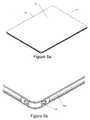
- FIGS. 6 a , 6 b and 6 cshow a removable display of an electronic document reader system
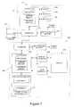
- FIG. 7shows a system block diagram for an electronic document reader system.
- an electronic document reader systemthat has a display holder and a removable display.
- the display and holdermay be connected together so that data and/or power may be supplied to the removable display, which is then useable to view electronic documents when removed from the holder.
- FIG. 1shows an electronic document reader system 1 , which comprises a display holder 10 that receives a removable display 50 .
- Electronic documentsare viewable on the removable display by a user.
- the holder 10performs one or more functions, including: mechanically supporting and/or protecting the removable display whilst the display is received in the holder; providing additional connectivity to the removable display; providing power and/or electronic document data to the display; and providing additional electronic functions and/or processing power to the display.
- the holder 10performs one or more functions, including: mechanically supporting and/or protecting the removable display whilst the display is received in the holder; providing additional connectivity to the removable display; providing power and/or electronic document data to the display; and providing additional electronic functions and/or processing power to the display.
- FIGS. 2 to 5show the display holder 10 of the electronic document reader system.
- the display holder 10has an open front 12 , a back 24 and an edge portion 14 .
- the open front 12is shaped to receive the removable display 50 .
- Various electronics and power supplyare housed in the edge portion 14 , and will be described in more detail below.
- the display holder 10has an electrical interface 18 to allow an electrical connection to the removable display 50 .
- the holderalso has retaining means 20 and 22 to retain the removable display in position, and one or more releasing flaps 16 a , 16 b to allow the removable display 50 to be removed from the holder 10 .
- the retaining means 22comprises a protrusion along an inside edge of the open front 12 .
- the protrusionis shown as a roughly convex shape. Of course, other shapes may be used instead.
- the protrusion 22is shaped to fit a correspondingly shaped recess in a corresponding edge of the removable display (which will be described later) so as to prevent the retained display edge from lifting from the holder.
- the retaining meanscomprises protrusions 20 on the inside edge of the open front 12 opposing the inside edge having the protrusion 22 .
- the protrusion 20(here shown as a roughly convex shape) is shaped to fit a correspondingly shaped recess a corresponding edge of the removable display so as to prevent the retained display edge from lifting from the holder.
- One or both of the protrusion 20 and 22may be spring-loaded to facilitate insertion of the removable display into the open front 12 of the holder 10 .
- the spring-loaded protrusion(s)are biased in a protruding position (as shown) and, during insertion of the removable display, the spring-loaded protrusion(s) are pushed into the respective inside edge so as to allow the display to be inserted. Once the display is inserted, the spring-loaded protrusion(s) extend into the protruding position (and thus engaging with the correspondingly shaped recess in the corresponding edge of the display) and retain the removable display until released.
- the releasing flaps 16 a , 16 blie flush with the surface of the open front 12 , extending away from the inside edge. Thus, the flaps 16 a , 16 b sit underneath the display when the display is received and held in the holder.
- a releasing panel or button 26is linked to the flaps 16 a , 16 b so that pressure applied to the button 26 causes the ends of the flaps to lift by pivoting about an axis along the inside edge of the open front.
- the lifting flapswhen operated, thus apply an upward force to the display received in the holder. The upward force is sufficient to overcome the spring-loaded protrusions 20 , 22 , so releasing the display from the holder.
- the protrusion 20forms part of the flap 16 b (flap 16 a also having a corresponding protrusion).
- the pivoting, lifting actionfurther causes the protrusion to retract, aiding the release of the display from the holder.
- the holder 10is designed to have a substantially similar appearance to that of the removable display 50 , and to have physical dimensions that are not substantially larger than the display 50 .
- Typical dimensions of the displayare 216 mm ⁇ 279 mm ⁇ 6 mm and typical dimensions of the holder are 251 mm ⁇ 289 mm ⁇ 7.5 mm.
- the open front 12 of the holderis shaped to receive the display 50 .
- the upper surface of the displaysits flush with the upper surface of the holder, to give the reader system the appearance of single, combined unit having a generally laminar shape. Since the holder and display have substantially similar appearances, the holder appears to the user as an extension of the display. Also in this position the display portion lies within the holder such that the back of the display portion (now towards the front) is substantially flush with the surrounding part of the holder.
- the display 50can be received within the open front 12 of the holder 10 in a forward position or a storage position. In both forward and storage positions, the holder 10 protects and/or mechanically supports the display 50 . In the forward position, a display portion of the display (which shall be described in detail below) faces towards the user so that the display is useable to view electronic documents whilst retained in the holder. In the storage position, the display portion of the display faces towards the bottom surface of the open front 12 . In such a position, the display portion is protected from external damage.
- the holder 10comprises one or more external connectors (not shown) to enable the holder to receive power from an external power source and to communicate with a computer and external peripherals such us a mouse, keyboard, monitors and other such peripherals.
- a computerexternal peripherals
- peripheralssuch as a mouse, keyboard, monitors and other such peripherals.
- Wired external connectors to provide communication between the holder and external computers and/or peripheralsinclude connectors such as USB and the like.
- external computers and/or peripheralsmay be coupled to the holder wirelessly using wireless protocols such as BluetoothTM, WiFi, HSDPA (High Speed Downlink Packet Access), 3G, and other like protocols. Through such wired and/or wireless connectors, data may be transferred to and from the holder.
- datamay pass in either direction between the holder and display, and the holder may provide power to the display.
- the holder 10may communicate with the display 50 through wireless protocols such as BluetoothTM and the like. As such, the display may actually communicate with the holder without being retained in the holder. However, it is preferable that the wireless protocol(s) used for communication between the holder and display are power efficient protocols to prolong the battery life of the display and/or holder.
- FIGS. 6 a , 6 b and 6 cshow a removable display 50 of an electronic document reader system 1 .
- the display 50has a front display surface 52 , which comprises a re-writeable display portion 54 and non-re-writeable portion bordering the re-writable display portion. Electronic documents are viewable on the re-writable display portion 54 .
- the front display surface 52is substantially flat to the edges of the removable display and, in particular, lacks a display bezel. As discussed, typical dimensions of the display are 216 mm ⁇ 279 mm ⁇ 6 mm.
- the re-writeable display portion 54is an electroactive display device such as a reflective bistable display. Examples of such displays include electrophoretic, LDC or other like displays. In preferred embodiments, the display is an electrophortetic display.
- the re-writable portion 54 of the display 50comprises a number of layers. From the upper-most surface, the re-writeable display portion 54 comprises a substantially transparent front panel, for example made of perspex, a moisture barrier, a layer of electrophoretic display, an active matrix pixel driver circuitry layer, a substrate and a further moisture layer.
- the active matrixmay comprise an array of organic or inorganic thin film transistors as disclosed, for example, in WO01/47045.
- the substrateis typically of plastic such as PET (polyethylene terephthalate).
- the electrophoretic displayis attached to the active matrix pixel driver circuitry layer by adhesive.
- the uppermost moisture barriersis, for example, of polyethylene and/or AclarTM, a fluoropolymer (polychlorotrifluoroethylene-PCTFE).
- the lower-most moisture barrier, under the substrate,does not need to be transparent. Therefore the lower-most moisture barrier may incorporate a metallic moisture barrier such as a layer of aluminium foil. This allows the lower-most moisture barrier to be thinner, hence enhancing overall flexibility.
- Approximate example thicknesses for the layersare as follows: 100 ⁇ m for moisture barrier 110 , 200 ⁇ m for substrate 108 , 5-6 ⁇ m for active layer 106 , 190 ⁇ m for electroactive display 104 , and 200 ⁇ m for moisture barrier 102 .
- These layersform an encapsulated electronic display; preferably this is bonded, for example by adhesive, to the uppermost transparent display panel.
- the display panelmay have a thickness in the range 0.5-2 mm, for example approximately 1 mm.
- the display mediumis a reflective display medium, in particular an electrophoretic display medium and the backplane comprises a flexible substrate such as PET or PEN (polyethylene naphthalene).
- the backplaneis fabricated using solution-based transistors preferably patterned by techniques such as direct-write printing, laser ablation or photolithography. Further details can be found in the applicant's earlier patent applications, including, in particular, WO01/47045, WO2004/070466, WO01/47043, WO 2006/059162, WO2006/056808, WO 2006/061658, WO2006/106365 and PCT/GB2006/050265, all hereby incorporated by reference in their entirety.
- control and power electronicsare contained in the display underneath the non-re-writeable and re-writable display portions.
- these electronicsinclude microprocessor, memory (volatile and non-volatile) and associated glue logic, together with a rechargeable power source and associated power management hardware and software.
- a non-re-writable display portionborders the re-writable display portion 54 .
- This display borderis coloured to substantially match the colour of the re-writable display portion 54 , which gives the appearance to the reader of a single display extending to the edges of the reader device.
- a boundary between the active display area and its borderis at least partially concealed and may be substantially invisible.
- the bordermay comprise a simple border, which may be, for example, sprayed onto the front panel.
- a uniform appearance to a user display edgingmay comprise electrophoretic display material such as an additional, undriven sheet of electrophoretic display or an undriven lateral extension of the re-writable electrophoretic display portion.
- electrophoretic display materialsuch as an additional, undriven sheet of electrophoretic display or an undriven lateral extension of the re-writable electrophoretic display portion.
- the colour of the holder, at least at the front,substantially matches a background colour of the non-volatile display.
- the removable display 50may also include a number of user controls for selecting documents to view on the display portion 54 and/or pages, turning pages of the electronic documents forward and back and the like.
- the border around the re-writeable display portion 54comprises touch sensitive elements.
- the displaymay be touch sensitive, for example as described in our co-pending international patent application PCT/GB2006/050220 hereby incorporated by reference in its entirety.
- Such sensorsmay include capacitive sensors or resistive touch sensors.
- the aforementioned patent applicationdescribes an arrangement in which a touch-screen component is positioned below the display, but which is nonetheless operable from the front, display surface, in particular by laminating the display medium and display backplane over a resistive touch-screen (using a pressure sensitive adhesive).
- documentsmay be electronically “marked-up”, with mark-up data being written to or being associated with the electronic document being displayed.
- the removable display 50comprises recesses 56 a , 56 b along its edges.
- the recessesare shaped to receive the protrusions 20 , 22 of the holder 10 for retaining the display in the open front 12 of the holder 10 .
- Additional holes 58may also be provided around the periphery of the display 50 to securely attach peripherals, such as pens or a stylus for controlling the display, to the edge of the display.
- the removable display 50comprises connectors 62 located along an edge of the device to enable the device to be connected to other electronic devices, such as a laptop or desktop computer, a PDA (Personal Digital Assistant), a mobile phone or ‘smart’ phone, or other such devices.
- a USB (universal serial bus) or similar connectoris, for example, provided.
- Such connectionsenable the transfer of electronic documents and other data between the display and other devices, and for the display to receive power.
- the displaymay also be provided with wireless interfaces (for example BluetoothTM or other such interfaces) to enable the transfer of electronic documents between the display and other devices.
- the displayalso comprises an electrical connector 60 to enable connection with the holder 10 .
- the electrical connector 60is disposed on an edge of the display 50 and comprises a row of electrical contacts, typically 6 to 8, that are shaped and positioned along the edge of the display so as to contact the correspondingly shaped and positioned internal electrical connector 18 located along an inside edge of the open front 12 of the holder 10 when the display is received in the holder.
- the electrical contactsthereby provide a wired connection between the display 50 and the holder 10 .
- the display 50comprises a second electrical connector (not shown) on an opposing edge of the display so that a connection between the holder and display may be maintained when the display is in either of the forward and storage positions.
- datamay pass in either direction between the holder and display, and the holder may provide power to the display.
- FIG. 7shows the electronic document reader system and example control circuitry suitable for the above-described electronic document reader system 1 .
- the control circuitry of the display 200comprises a controller 202 including a processor, working memory and programme memory, coupled to a user interface 216 (for example touch sensitive controls).
- the controlleris also coupled to the active matrix driver circuitry of the display 212 by a display interface 214 for example provided by integrated circuits.
- controller 202is able to send electronic documents and electronic document data to the display 212 and, optionally, to receive touch-sense data from the display 212 .
- the control electronicsalso includes non-volatile memory 210 , for example Flash memory for storing data for one or more electronic documents for display and, optionally, other data such as user bookmark locations and the like.
- An interface 204is provided for interfacing with the holder 100 to receive electronic document data and, optionally, to provide data such as user bookmark data.
- the interface 204may comprise a wired (for example through the electrical connectors 60 , 18 ) and/or wireless, for example BluetoothTM, interface. Power is also transferred through the interface 204 to power the display 200 and associated control electronics and/or to recharge a rechargeable battery 206 .
- the display 200may instead be connected directly to a computer 300 or other devices via the interface.
- the interface 204may comprise a wired (for example a USB connector) and/or wireless, for example BluetoothTM, interface.
- processor control code for a wide range of functionsmay be stored in the programme memory.
- a simple document display proceduremay comprise, in operation, sensing a user control, determining which document to update, reading a portion of the relevant document from the non-volatile memory, and writing the read portion of the document to the page display.
- the removable displayis useable to view electronic documents whilst in connection with the display holder and/or computer and/or additional peripherals, as well as removed from the holder and/or computer and/or additional peripherals.
- the display holder 100has control circuitry comprising a controller 202 including a processor, working memory and programme memory, coupled to an interface 104 and one or more modules 108 .
- the control electronicsalso includes non-volatile memory, for example Flash memory for storing data for one or more electronic documents for display on the removable display 200 and additional storage media (not shown) for storing electronic documents and associated data.
- the interface 104is provided for interfacing with the display 200 to transmit and receive electronic document data.
- the interface 104may comprise a wired (for example through the electrical connectors 60 , 18 ) and/or wireless, for example BluetoothTM, interface. Power is also transferred through the interface 104 to power the display 200 and associated control electronics and/or to recharge a rechargeable battery 106 of the display holder.
- the interface 104provides a connection to external computers ( 300 ) and other peripherals, either through wired connectors (for example USB) and/or wireless protocols (for example BluetoothTM, WiFi, 3G and other like protocols) so that electronic documents and their associated data my be transmitted to and received from such connected computers and/or peripherals.
- the interface 104also receives power from external sources (such as from a computer connected to the USB wired port or through a dedicated mains connection) to power the display holder electronics and/or recharge the rechargeable batter 106 .
- Each of the one or more modules 108are specific to different functional applications of the display holder 100 . Different display holders may have different modules. Therefore, different display holders may be targeted at specific markets, or for specific applications.
- Some examples of modulesinclude: GPS (Global Positioning System), additional storage media, an Internet connection browser, a keyboard or other physical user interface-based document editor/processor, an expansion card/device module, a module for formatting a document for viewing on the removable display, or additional graphical or general processors, and modules for other specific application programs residing in the memory of the holder. Each of the modules has associated with them software and/or hardware to perform the desired function.
- the display holderprovides the display with an additional power source, processing power and/or functionality (via the one or more modules).
- the userplaces the removable display 200 within the holder, thus enabling the internal connectors to make a connection between the holder and display.
- the holderprovides at least power to the display to recharge the display's rechargeable battery.
- Connecting a computer 300 to the holderenables the transfer of electronic documents stored on the computer to the memory of the holder and display.
- the usermay designate the electronic documents to transfer to the holder and display via a graphical user interface on the computer or the display itself.
- the processmay be automated, and all of the electronic documents present on the computer that are not present on the holder and/or display are transferred to the holder and/or display. In such a method, the electronic documents on the computer, holder and display are synchronised.
- the userdetaches the holder from the computer and/or power source.
- the usermay transport the display in the holder in either of the forward or storage positions (as discussed above). Should the user not require access to the electronic documents, the user stores the display in the storage position to protect the display area of the screen from damage or scratches that might occur during transit. In the storage position, power is provided to the display's rechargeable battery by the holder's rechargeable power source.
- the userWhilst connected to the holder and with the display in the forward position, the user may use the display to view the electronic document. From the graphical user interface of the display and the touch sensors on the display surface, the user may control the viewing of the electronic documents (and record user annotations of the electronic documents should touch sensors be provided over the re-writeable portion of the display). Since the display is connected to the holder, the user may also control or use other peripherals connected to the holder, and may also use any applications specific to that holder (for example GPS, WiFi, 3G).
- any applications specific to that holderfor example GPS, WiFi, 3G.
- the displaymay be released from the holder (as described above). Whilst released and removed from the holder, the user may use the display as before i.e. the user may use the graphical user interface of the display and the touch sensors (or keyboard such as a touch keyboard) on the display surface to control the viewing of the electronic documents (and record user annotations of the electronic documents should touch sensors be provided over the re-writeable portion of the display).
- the touch sensorsor keyboard such as a touch keyboard
- the usermay also connect to various peripherals such as external projectors, a mouse, printers and the like using the wired or wireless interfaces.
- peripheralssuch as external projectors, a mouse, printers and the like using the wired or wireless interfaces.
- the userAfter the business trip, the user returns and connected and the display and holder to the computer. Power is again received from the computer and/or external power source to recharge the holder and display's rechargeable battery. As with the display and holder, any annotations or changes made to the electronic documents whilst the display and/or holder were remote from the computer are synchronised with the copy of the electronic documents stored in the computer.
Landscapes
- Engineering & Computer Science (AREA)
- Theoretical Computer Science (AREA)
- Computer Hardware Design (AREA)
- Human Computer Interaction (AREA)
- Physics & Mathematics (AREA)
- General Engineering & Computer Science (AREA)
- General Physics & Mathematics (AREA)
- Devices For Indicating Variable Information By Combining Individual Elements (AREA)
- Facsimiles In General (AREA)
Abstract
Description
Claims (26)
Applications Claiming Priority (2)
| Application Number | Priority Date | Filing Date | Title |
|---|---|---|---|
| GB0803915.8 | 2008-03-03 | ||
| GB0803915.8AGB2458106B (en) | 2008-03-03 | 2008-03-03 | Electronic document reader system |
Publications (2)
| Publication Number | Publication Date |
|---|---|
| US20090219271A1 US20090219271A1 (en) | 2009-09-03 |
| US8228323B2true US8228323B2 (en) | 2012-07-24 |
Family
ID=39315848
Family Applications (1)
| Application Number | Title | Priority Date | Filing Date |
|---|---|---|---|
| US12/139,011Expired - Fee RelatedUS8228323B2 (en) | 2008-03-03 | 2008-06-13 | Electronic document reader system |
Country Status (2)
| Country | Link |
|---|---|
| US (1) | US8228323B2 (en) |
| GB (1) | GB2458106B (en) |
Cited By (10)
| Publication number | Priority date | Publication date | Assignee | Title |
|---|---|---|---|---|
| US20110175902A1 (en)* | 2010-01-20 | 2011-07-21 | Apple Inc. | Multilayer display device |
| US9176536B2 (en) | 2011-09-30 | 2015-11-03 | Apple, Inc. | Wireless display for electronic devices |
| US20160291639A1 (en)* | 2013-11-26 | 2016-10-06 | Hewlett-Packard Development Company, L.P. | Electronic device accessory with at least one port |
| US9810942B2 (en) | 2012-06-15 | 2017-11-07 | Apple Inc. | Quantum dot-enhanced display having dichroic filter |
| US10783613B2 (en) | 2013-09-27 | 2020-09-22 | Kofax, Inc. | Content-based detection and three dimensional geometric reconstruction of objects in image and video data |
| US10803350B2 (en)* | 2017-11-30 | 2020-10-13 | Kofax, Inc. | Object detection and image cropping using a multi-detector approach |
| US11062163B2 (en) | 2015-07-20 | 2021-07-13 | Kofax, Inc. | Iterative recognition-guided thresholding and data extraction |
| US11087407B2 (en) | 2012-01-12 | 2021-08-10 | Kofax, Inc. | Systems and methods for mobile image capture and processing |
| US11302109B2 (en) | 2015-07-20 | 2022-04-12 | Kofax, Inc. | Range and/or polarity-based thresholding for improved data extraction |
| US11321772B2 (en) | 2012-01-12 | 2022-05-03 | Kofax, Inc. | Systems and methods for identification document processing and business workflow integration |
Families Citing this family (11)
| Publication number | Priority date | Publication date | Assignee | Title |
|---|---|---|---|---|
| GB0702350D0 (en)* | 2007-02-07 | 2007-03-21 | Plastic Logic Ltd | Electronic reading devices |
| GB0702349D0 (en)* | 2007-02-07 | 2007-03-21 | Plastic Logic Ltd | Electronic document readers and reading devices |
| GB0702347D0 (en)* | 2007-02-07 | 2007-03-21 | Plastic Logic Ltd | Electronic document reading devices |
| GB2454032A (en)* | 2007-10-24 | 2009-04-29 | Plastic Logic Ltd | Edgeless document viewer |
| GB2458106B (en) | 2008-03-03 | 2012-07-18 | Plastic Logic Ltd | Electronic document reader system |
| US9188976B1 (en)* | 2009-09-02 | 2015-11-17 | Amazon Technologies, Inc. | Content enabling cover for electronic book reader devices |
| US8866581B1 (en) | 2010-03-09 | 2014-10-21 | Amazon Technologies, Inc. | Securing content using a wireless authentication factor |
| US8909838B2 (en) | 2010-06-24 | 2014-12-09 | Microsoft Corporation | Detachable computer with variable performance computing environment |
| US20120326003A1 (en)* | 2011-06-27 | 2012-12-27 | Solow Michael L | Multi-function tablet computer grip with 360-degree rotating finger ringlet |
| US10427445B2 (en)* | 2013-09-12 | 2019-10-01 | Susan Francesca HUDACHEK | Illuminatable assembly |
| KR102357391B1 (en)* | 2015-08-31 | 2022-02-03 | 삼성디스플레이 주식회사 | Display apparatus and method of driving the same |
Citations (52)
| Publication number | Priority date | Publication date | Assignee | Title |
|---|---|---|---|---|
| US4453200A (en) | 1981-07-20 | 1984-06-05 | Rockwell International Corporation | Apparatus for lighting a passive display |
| EP0283235A2 (en) | 1987-03-14 | 1988-09-21 | Sharp Kabushiki Kaisha | Liquid crystal display device |
| US4856088A (en) | 1988-01-14 | 1989-08-08 | Motorola, Inc. | Radio with removable display |
| GB2214342A (en) | 1988-01-19 | 1989-08-31 | Mitsubishi Electric Corp | Liquid crystal display apparatus |
| US5347630A (en) | 1991-04-23 | 1994-09-13 | Seiko Epson Corporation | Computer system having a detachable display |
| WO1995023367A1 (en) | 1994-02-28 | 1995-08-31 | Ing. C. Olivetti & C., S.P.A. | Portable electronic computer |
| US5508720A (en)* | 1994-02-02 | 1996-04-16 | Copytele, Inc. | Portable telecommunication device with removable electrophoretic display |
| JPH1027162A (en) | 1996-07-11 | 1998-01-27 | Oki Electric Ind Co Ltd | Portable electronic equipment |
| US5857157A (en) | 1995-06-06 | 1999-01-05 | Sony Corporation | Portable communication terminal apparatus |
| US5956034A (en) | 1996-08-13 | 1999-09-21 | Softbook Press, Inc. | Method and apparatus for viewing electronic reading materials |
| US6297945B1 (en) | 1999-03-29 | 2001-10-02 | Ricoh Company, Ltd. | Portable electronic terminal apparatus having a plurality of displays |
| US20020018027A1 (en) | 2000-06-22 | 2002-02-14 | Koichio Sugimoto | Information processing apparatus and information output controlling method |
| US6388877B1 (en) | 1999-02-04 | 2002-05-14 | Palm, Inc. | Handheld computer with open accessory slot |
| US20020102866A1 (en) | 2000-12-28 | 2002-08-01 | Jean-Pierre Lubowicki | Electronic apparatus comprising two mutually movable parts |
| US6456732B1 (en) | 1998-09-11 | 2002-09-24 | Hewlett-Packard Company | Automatic rotation, cropping and scaling of images for printing |
| WO2002095555A2 (en) | 2001-05-18 | 2002-11-28 | Palm, Inc. | Portable computer system |
| WO2003017245A1 (en) | 2001-08-17 | 2003-02-27 | Palm, Inc. | Handheld computer with variable size |
| EP1308825A1 (en) | 2001-11-01 | 2003-05-07 | Eastman Kodak Company | Detachable flat panel display |
| WO2003044765A2 (en) | 2001-11-20 | 2003-05-30 | E Ink Corporation | Methods for driving bistable electro-optic displays |
| EP1355221A2 (en) | 2002-04-18 | 2003-10-22 | Gateway, Inc. | Computer having detachable wireless independently operable computer |
| US6661920B1 (en) | 2000-01-19 | 2003-12-09 | Palm Inc. | Method and apparatus for multiple simultaneously active data entry mechanisms on a computer system |
| US20040008398A1 (en) | 2002-06-27 | 2004-01-15 | E Ink Corporation | Illumination system for nonemissive electronic displays |
| US20040246666A1 (en) | 2003-06-09 | 2004-12-09 | Arif Maskatia | Portable electronic device with a docking unit |
| US6831662B1 (en) | 2000-11-08 | 2004-12-14 | Palmone, Inc. | Apparatus and methods to achieve a variable color pixel border on a negative mode screen with a passive matrix drive |
| WO2004114259A2 (en) | 2003-06-23 | 2004-12-29 | Simon Richard Daniel | Display device having an extendible screen |
| US20040268004A1 (en) | 2003-06-27 | 2004-12-30 | Oakley Nicholas W | Always-on removable communicator display |
| US20050025387A1 (en) | 2003-07-31 | 2005-02-03 | Eastman Kodak Company | Method and computer program product for producing an image of a desired aspect ratio |
| US6888643B1 (en) | 2000-06-16 | 2005-05-03 | International Business Machines Corporation | Method and system for printing documents to a reusable medium |
| US6919879B2 (en) | 1998-06-26 | 2005-07-19 | Research In Motion Limited | Hand-held electronic device with a keyboard optimized for use with the thumbs |
| US20050206580A1 (en) | 2003-12-16 | 2005-09-22 | Fumio Koyama | Information display |
| JP2005266968A (en) | 2004-03-16 | 2005-09-29 | Toshiba Corp | Electronics |
| JP2005274832A (en) | 2004-03-24 | 2005-10-06 | Matsushita Electric Ind Co Ltd | Reflective liquid crystal display with auxiliary light source |
| US20050237444A1 (en) | 2004-04-23 | 2005-10-27 | Lg.Philips Lcd Co., Ltd. | Liquid crystal display device |
| US6961029B1 (en) | 2000-11-08 | 2005-11-01 | Palm, Inc. | Pixel border for improved viewability of a display device |
| US20050257143A1 (en) | 2002-05-22 | 2005-11-17 | The Appliance Studio Limited | Printing to displays |
| US20060026536A1 (en) | 2004-07-30 | 2006-02-02 | Apple Computer, Inc. | Gestures for touch sensitive input devices |
| WO2006031347A2 (en) | 2004-08-13 | 2006-03-23 | E Ink Corporation | Methods and apparatus for driving electro-optic displays |
| US7058829B2 (en) | 2002-08-14 | 2006-06-06 | Intel Corporation | Method and apparatus for a computing system having an active sleep mode CPU that uses the cache of a normal active mode CPU |
| US7079111B2 (en) | 1997-12-18 | 2006-07-18 | E-Book Systems Pte Ltd | Computer based browsing computer program product, system and method |
| US20060274549A1 (en) | 2005-06-07 | 2006-12-07 | Nec Lcd Technologies, Ltd. | Multi-panel display apparatus |
| US20070024603A1 (en) | 2005-07-28 | 2007-02-01 | Li Xiao-Chang C | Integrated digital picture viewing device |
| US20070028086A1 (en) | 1990-03-23 | 2007-02-01 | Mitsuaki Oshima | Data processing apparatus |
| US20070058178A1 (en) | 2005-09-13 | 2007-03-15 | Fuji Xerox Co., Ltd. | Electronic paper system, image processing apparatus for electronic paper system storage medium storing image processing program, and image writing method using image processing apparatus |
| US20070115258A1 (en) | 2001-03-16 | 2007-05-24 | Dualcor Technologies, Inc. | Personal electronic device with display switching |
| US20070195009A1 (en) | 2006-01-31 | 2007-08-23 | Sadao Yamamoto | Information processing device and related method |
| US20070213105A1 (en) | 2001-01-26 | 2007-09-13 | Dell Products L.P. | Removable personal digital assistant in a dual personal computer/personal digital assistant computer architecture |
| US7289084B2 (en) | 2005-02-22 | 2007-10-30 | John Michael Lesniak | Computer display apparatus |
| GB2446500A (en) | 2007-02-07 | 2008-08-13 | Plastic Logic Ltd | Electronic document reading device with its centre of gravity is in the lower half of the device so that the device can be used by one hand |
| GB2446499A (en) | 2007-02-07 | 2008-08-13 | Plastic Logic Ltd | Flexible display for a an electronic document reading device with a perimeter frame on the underside of the screen |
| US20080298083A1 (en) | 2007-02-07 | 2008-12-04 | Ben Watson | Electronic reading devices |
| GB2454032A (en) | 2007-10-24 | 2009-04-29 | Plastic Logic Ltd | Edgeless document viewer |
| US20090219271A1 (en) | 2008-03-03 | 2009-09-03 | Carano Bandel | Electronic document reader system |
Family Cites Families (1)
| Publication number | Priority date | Publication date | Assignee | Title |
|---|---|---|---|---|
| US5587157A (en)* | 1992-05-19 | 1996-12-24 | Cox; James P. | Stabilization of biowastes |
- 2008
- 2008-03-03GBGB0803915.8Apatent/GB2458106B/ennot_activeExpired - Fee Related
- 2008-06-13USUS12/139,011patent/US8228323B2/ennot_activeExpired - Fee Related
Patent Citations (64)
| Publication number | Priority date | Publication date | Assignee | Title |
|---|---|---|---|---|
| US4453200A (en) | 1981-07-20 | 1984-06-05 | Rockwell International Corporation | Apparatus for lighting a passive display |
| EP0283235A2 (en) | 1987-03-14 | 1988-09-21 | Sharp Kabushiki Kaisha | Liquid crystal display device |
| US4856088A (en) | 1988-01-14 | 1989-08-08 | Motorola, Inc. | Radio with removable display |
| GB2214342A (en) | 1988-01-19 | 1989-08-31 | Mitsubishi Electric Corp | Liquid crystal display apparatus |
| US20070028086A1 (en) | 1990-03-23 | 2007-02-01 | Mitsuaki Oshima | Data processing apparatus |
| US5347630A (en) | 1991-04-23 | 1994-09-13 | Seiko Epson Corporation | Computer system having a detachable display |
| US5508720A (en)* | 1994-02-02 | 1996-04-16 | Copytele, Inc. | Portable telecommunication device with removable electrophoretic display |
| WO1995023367A1 (en) | 1994-02-28 | 1995-08-31 | Ing. C. Olivetti & C., S.P.A. | Portable electronic computer |
| US5857157A (en) | 1995-06-06 | 1999-01-05 | Sony Corporation | Portable communication terminal apparatus |
| JPH1027162A (en) | 1996-07-11 | 1998-01-27 | Oki Electric Ind Co Ltd | Portable electronic equipment |
| US5956034A (en) | 1996-08-13 | 1999-09-21 | Softbook Press, Inc. | Method and apparatus for viewing electronic reading materials |
| US7079111B2 (en) | 1997-12-18 | 2006-07-18 | E-Book Systems Pte Ltd | Computer based browsing computer program product, system and method |
| US6919879B2 (en) | 1998-06-26 | 2005-07-19 | Research In Motion Limited | Hand-held electronic device with a keyboard optimized for use with the thumbs |
| US6456732B1 (en) | 1998-09-11 | 2002-09-24 | Hewlett-Packard Company | Automatic rotation, cropping and scaling of images for printing |
| US6388877B1 (en) | 1999-02-04 | 2002-05-14 | Palm, Inc. | Handheld computer with open accessory slot |
| US6297945B1 (en) | 1999-03-29 | 2001-10-02 | Ricoh Company, Ltd. | Portable electronic terminal apparatus having a plurality of displays |
| US6661920B1 (en) | 2000-01-19 | 2003-12-09 | Palm Inc. | Method and apparatus for multiple simultaneously active data entry mechanisms on a computer system |
| US6888643B1 (en) | 2000-06-16 | 2005-05-03 | International Business Machines Corporation | Method and system for printing documents to a reusable medium |
| US20020018027A1 (en) | 2000-06-22 | 2002-02-14 | Koichio Sugimoto | Information processing apparatus and information output controlling method |
| US6961029B1 (en) | 2000-11-08 | 2005-11-01 | Palm, Inc. | Pixel border for improved viewability of a display device |
| US6831662B1 (en) | 2000-11-08 | 2004-12-14 | Palmone, Inc. | Apparatus and methods to achieve a variable color pixel border on a negative mode screen with a passive matrix drive |
| US20020102866A1 (en) | 2000-12-28 | 2002-08-01 | Jean-Pierre Lubowicki | Electronic apparatus comprising two mutually movable parts |
| US20070213105A1 (en) | 2001-01-26 | 2007-09-13 | Dell Products L.P. | Removable personal digital assistant in a dual personal computer/personal digital assistant computer architecture |
| US20070115258A1 (en) | 2001-03-16 | 2007-05-24 | Dualcor Technologies, Inc. | Personal electronic device with display switching |
| WO2002095555A2 (en) | 2001-05-18 | 2002-11-28 | Palm, Inc. | Portable computer system |
| WO2003017245A1 (en) | 2001-08-17 | 2003-02-27 | Palm, Inc. | Handheld computer with variable size |
| EP1308825A1 (en) | 2001-11-01 | 2003-05-07 | Eastman Kodak Company | Detachable flat panel display |
| US20030090480A1 (en)* | 2001-11-01 | 2003-05-15 | Eastman Kodak Company | Disaggregated flat panel display |
| WO2003044765A2 (en) | 2001-11-20 | 2003-05-30 | E Ink Corporation | Methods for driving bistable electro-optic displays |
| EP1355221A2 (en) | 2002-04-18 | 2003-10-22 | Gateway, Inc. | Computer having detachable wireless independently operable computer |
| US20050257143A1 (en) | 2002-05-22 | 2005-11-17 | The Appliance Studio Limited | Printing to displays |
| US20040008398A1 (en) | 2002-06-27 | 2004-01-15 | E Ink Corporation | Illumination system for nonemissive electronic displays |
| US7058829B2 (en) | 2002-08-14 | 2006-06-06 | Intel Corporation | Method and apparatus for a computing system having an active sleep mode CPU that uses the cache of a normal active mode CPU |
| US20040246666A1 (en) | 2003-06-09 | 2004-12-09 | Arif Maskatia | Portable electronic device with a docking unit |
| WO2004114259A2 (en) | 2003-06-23 | 2004-12-29 | Simon Richard Daniel | Display device having an extendible screen |
| US20040268004A1 (en) | 2003-06-27 | 2004-12-30 | Oakley Nicholas W | Always-on removable communicator display |
| US20050025387A1 (en) | 2003-07-31 | 2005-02-03 | Eastman Kodak Company | Method and computer program product for producing an image of a desired aspect ratio |
| US20050206580A1 (en) | 2003-12-16 | 2005-09-22 | Fumio Koyama | Information display |
| JP2005266968A (en) | 2004-03-16 | 2005-09-29 | Toshiba Corp | Electronics |
| JP2005274832A (en) | 2004-03-24 | 2005-10-06 | Matsushita Electric Ind Co Ltd | Reflective liquid crystal display with auxiliary light source |
| US20050237444A1 (en) | 2004-04-23 | 2005-10-27 | Lg.Philips Lcd Co., Ltd. | Liquid crystal display device |
| US20060026536A1 (en) | 2004-07-30 | 2006-02-02 | Apple Computer, Inc. | Gestures for touch sensitive input devices |
| WO2006031347A2 (en) | 2004-08-13 | 2006-03-23 | E Ink Corporation | Methods and apparatus for driving electro-optic displays |
| US7289084B2 (en) | 2005-02-22 | 2007-10-30 | John Michael Lesniak | Computer display apparatus |
| US20060274549A1 (en) | 2005-06-07 | 2006-12-07 | Nec Lcd Technologies, Ltd. | Multi-panel display apparatus |
| US20070024603A1 (en) | 2005-07-28 | 2007-02-01 | Li Xiao-Chang C | Integrated digital picture viewing device |
| US20070058178A1 (en) | 2005-09-13 | 2007-03-15 | Fuji Xerox Co., Ltd. | Electronic paper system, image processing apparatus for electronic paper system storage medium storing image processing program, and image writing method using image processing apparatus |
| US20070195009A1 (en) | 2006-01-31 | 2007-08-23 | Sadao Yamamoto | Information processing device and related method |
| US20080298083A1 (en) | 2007-02-07 | 2008-12-04 | Ben Watson | Electronic reading devices |
| GB2446499A (en) | 2007-02-07 | 2008-08-13 | Plastic Logic Ltd | Flexible display for a an electronic document reading device with a perimeter frame on the underside of the screen |
| US20080297470A1 (en) | 2007-02-07 | 2008-12-04 | Matthew Marsh | Electronic document readers and reading devices |
| US20080297496A1 (en) | 2007-02-07 | 2008-12-04 | Ben Watson | Electronic document reading devices |
| GB2446500A (en) | 2007-02-07 | 2008-08-13 | Plastic Logic Ltd | Electronic document reading device with its centre of gravity is in the lower half of the device so that the device can be used by one hand |
| US20090109498A1 (en) | 2007-10-24 | 2009-04-30 | Duncan Barclay | Electronic document reading devices |
| GB2454033A (en) | 2007-10-24 | 2009-04-29 | Plastic Logic Ltd | Portable paperless electronic printer |
| GB2454032A (en) | 2007-10-24 | 2009-04-29 | Plastic Logic Ltd | Edgeless document viewer |
| WO2009053740A1 (en) | 2007-10-24 | 2009-04-30 | Plastic Logic Limited | Electronic document reader |
| WO2009053738A1 (en) | 2007-10-24 | 2009-04-30 | Plastic Logic Limited | Document printing techniques |
| US20090109185A1 (en) | 2007-10-24 | 2009-04-30 | Plastic Logic Limited | Electronic Document Reader |
| WO2009053747A1 (en) | 2007-10-24 | 2009-04-30 | Plastic Logic Limited | Electronic document reading devices |
| US20090109468A1 (en) | 2007-10-24 | 2009-04-30 | Duncan Barclay | Document printing techniques |
| WO2009053743A1 (en) | 2007-10-24 | 2009-04-30 | Plastic Logic Limited | Electronic document reader |
| US20090113291A1 (en) | 2007-10-24 | 2009-04-30 | Plastic Logic Limited | Electronic Document Reader |
| US20090219271A1 (en) | 2008-03-03 | 2009-09-03 | Carano Bandel | Electronic document reader system |
Non-Patent Citations (15)
| Title |
|---|
| Iddo Genuth: "the Future of Electronic Paper" [Online]; Oct. 15, 2007, XP002513292; http://thefutureofthings.com/articles/1000/the-future-of-electronic-paper.html. |
| International Search Report; GB 0802816.9; J. McCann; May 23, 2008. |
| International Search Report; GB 0802818.5; J. McCann; May 29, 2008. |
| International Search Report; GB0801998.6; D. Maskery; May 28, 2008. |
| International Search Report; PCT/GB2008/050975; Feb. 20, 2009; E. Maciu. |
| International Search Report; PCT/GB2008/050977; Feb. 19, 2009; E. Maciu. |
| International Search Report; PCT/GB2008/050980; Feb. 23, 2009; E. Maciu. |
| Search Report and Examiner Letter for Application No. GB0802011.7 (dated Aug. 27, 2009). |
| Search Report; GB 0801987.9; D. Maskery; May 19, 2008. |
| Search Report; GB 0802011.7; R. Jenkins; Jun. 18, 2008. |
| Search Report; GB 0803915.8; D. Maskery; Jun. 17, 2008. |
| Search Report; GB0802820.1; R. Jenkins; Sep. 12, 2008. |
| USPTO Office Action in U.S. Appl. No. 12/027,176, mailed Jun. 4, 2009, 12 pages. |
| www.palm.com, Palm Z22, T/X, and Tungsten E2 handhelds (copyright 2005). |
| www.palm.com; Palm Z22,T| and Tungsten E2 handhelds. |
Cited By (12)
| Publication number | Priority date | Publication date | Assignee | Title |
|---|---|---|---|---|
| US20110175902A1 (en)* | 2010-01-20 | 2011-07-21 | Apple Inc. | Multilayer display device |
| US9176536B2 (en) | 2011-09-30 | 2015-11-03 | Apple, Inc. | Wireless display for electronic devices |
| US11087407B2 (en) | 2012-01-12 | 2021-08-10 | Kofax, Inc. | Systems and methods for mobile image capture and processing |
| US11321772B2 (en) | 2012-01-12 | 2022-05-03 | Kofax, Inc. | Systems and methods for identification document processing and business workflow integration |
| US9810942B2 (en) | 2012-06-15 | 2017-11-07 | Apple Inc. | Quantum dot-enhanced display having dichroic filter |
| US10783613B2 (en) | 2013-09-27 | 2020-09-22 | Kofax, Inc. | Content-based detection and three dimensional geometric reconstruction of objects in image and video data |
| US20160291639A1 (en)* | 2013-11-26 | 2016-10-06 | Hewlett-Packard Development Company, L.P. | Electronic device accessory with at least one port |
| US9753494B2 (en)* | 2013-11-26 | 2017-09-05 | Hewlett-Packard Development Company, L.P. | Electronic device accessory with at least one port |
| US11062163B2 (en) | 2015-07-20 | 2021-07-13 | Kofax, Inc. | Iterative recognition-guided thresholding and data extraction |
| US11302109B2 (en) | 2015-07-20 | 2022-04-12 | Kofax, Inc. | Range and/or polarity-based thresholding for improved data extraction |
| US10803350B2 (en)* | 2017-11-30 | 2020-10-13 | Kofax, Inc. | Object detection and image cropping using a multi-detector approach |
| US11062176B2 (en) | 2017-11-30 | 2021-07-13 | Kofax, Inc. | Object detection and image cropping using a multi-detector approach |
Also Published As
| Publication number | Publication date |
|---|---|
| GB2458106B (en) | 2012-07-18 |
| US20090219271A1 (en) | 2009-09-03 |
| GB2458106A (en) | 2009-09-09 |
| GB0803915D0 (en) | 2008-04-09 |
Similar Documents
| Publication | Publication Date | Title |
|---|---|---|
| US8228323B2 (en) | Electronic document reader system | |
| CN104350445B (en) | Electronic reading device | |
| EP3440505B1 (en) | Borderless display with curved edges | |
| US9001024B2 (en) | Electronic document reader | |
| US20130040657A1 (en) | Electronic document reading devices | |
| US8203546B2 (en) | Electronic document reading devices | |
| CN106325496B (en) | Electronic device with force touch function | |
| CN107003702B (en) | Electronic equipment stack assemblies | |
| KR101396373B1 (en) | Writing tablet information recording device | |
| KR102473527B1 (en) | Electronic device | |
| US8619021B2 (en) | Electronic document reading devices | |
| GB2504944A (en) | Wrapable flexible display for attaching to a smartphone etc. with control of display contents following display form. | |
| WO2014057241A1 (en) | Foldable electronic display | |
| JP2013210491A (en) | Display device and electronic apparatus | |
| US20150296063A1 (en) | Electronic device | |
| CN105321430A (en) | Foldable display apparatus | |
| CN104135550A (en) | Portable electronic device, flip-type protective cover and control method thereof | |
| WO2015008009A1 (en) | Assembly of multiple flexible displays | |
| TW201643852A (en) | Electronic paper display device | |
| US9268925B2 (en) | Electronic paper with mode switch unit | |
| US9423891B2 (en) | Shared digitizer | |
| US8345073B1 (en) | Touch screen layer reduction | |
| US20100142133A1 (en) | Electronic device with touch panel | |
| US9819815B1 (en) | Surface display assembly having proximate active elements | |
| KR20210058148A (en) | Flexible display apparatus using shape memory member |
Legal Events
| Date | Code | Title | Description |
|---|---|---|---|
| AS | Assignment | Owner name:PLASTIC LOGIC LIMITED, UNITED KINGDOM Free format text:ASSIGNMENT OF ASSIGNORS INTEREST;ASSIGNORS:BANDEL, CARANO;HAUSER, HERMANN;HAYTON, CARL;AND OTHERS;REEL/FRAME:022145/0219;SIGNING DATES FROM 20051205 TO 20090122 Owner name:PLASTIC LOGIC LIMITED, UNITED KINGDOM Free format text:ASSIGNMENT OF ASSIGNORS INTEREST;ASSIGNORS:BANDEL, CARANO;HAUSER, HERMANN;HAYTON, CARL;AND OTHERS;SIGNING DATES FROM 20051205 TO 20090122;REEL/FRAME:022145/0219 | |
| AS | Assignment | Owner name:STATE CORPORATION "RUSSIAN CORPORATION OF NANOTECH Free format text:SECURITY AGREEMENT;ASSIGNOR:PLASTIC LOGIC LIMITED;REEL/FRAME:024776/0357 Effective date:20100802 | |
| AS | Assignment | Owner name:PLASTIC LOGIC LIMITED, UNITED KINGDOM Free format text:RELEASE BY SECURED PARTY;ASSIGNOR:STATE CORPORATION "RUSSIAN CORPORATION OF NANOTECHNOLOGIES";REEL/FRAME:026271/0377 Effective date:20110415 | |
| STCF | Information on status: patent grant | Free format text:PATENTED CASE | |
| FEPP | Fee payment procedure | Free format text:PAT HOLDER NO LONGER CLAIMS SMALL ENTITY STATUS, ENTITY STATUS SET TO UNDISCOUNTED (ORIGINAL EVENT CODE: STOL); ENTITY STATUS OF PATENT OWNER: LARGE ENTITY | |
| AS | Assignment | Owner name:FLEXENABLE LIMITED, UNITED KINGDOM Free format text:CHANGE OF NAME;ASSIGNOR:PLASTIC LOGIC LIMITED;REEL/FRAME:035061/0110 Effective date:20001101 | |
| FPAY | Fee payment | Year of fee payment:4 | |
| FEPP | Fee payment procedure | Free format text:MAINTENANCE FEE REMINDER MAILED (ORIGINAL EVENT CODE: REM.); ENTITY STATUS OF PATENT OWNER: LARGE ENTITY | |
| LAPS | Lapse for failure to pay maintenance fees | Free format text:PATENT EXPIRED FOR FAILURE TO PAY MAINTENANCE FEES (ORIGINAL EVENT CODE: EXP.); ENTITY STATUS OF PATENT OWNER: LARGE ENTITY | |
| STCH | Information on status: patent discontinuation | Free format text:PATENT EXPIRED DUE TO NONPAYMENT OF MAINTENANCE FEES UNDER 37 CFR 1.362 | |
| FP | Lapsed due to failure to pay maintenance fee | Effective date:20200724 |