US8227682B2 - Same plane multiple thermoelectric mounting system - Google Patents
Same plane multiple thermoelectric mounting systemDownload PDFInfo
- Publication number
- US8227682B2 US8227682B2US10/823,353US82335304AUS8227682B2US 8227682 B2US8227682 B2US 8227682B2US 82335304 AUS82335304 AUS 82335304AUS 8227682 B2US8227682 B2US 8227682B2
- Authority
- US
- United States
- Prior art keywords
- fluid
- thermal
- modules
- thermoelectric
- module
- Prior art date
- Legal status (The legal status is an assumption and is not a legal conclusion. Google has not performed a legal analysis and makes no representation as to the accuracy of the status listed.)
- Expired - Fee Related, expires
Links
- 239000012530fluidSubstances0.000claimsdescription96
- 230000005611electricityEffects0.000claimsdescription36
- 230000006835compressionEffects0.000claimsdescription13
- 238000007906compressionMethods0.000claimsdescription13
- 230000008602contractionEffects0.000claimsdescription5
- XLYOFNOQVPJJNP-UHFFFAOYSA-NwaterSubstancesOXLYOFNOQVPJJNP-UHFFFAOYSA-N0.000claimsdescription3
- 239000007788liquidSubstances0.000claims2
- 238000003754machiningMethods0.000abstract1
- 238000012423maintenanceMethods0.000abstract1
- 238000010438heat treatmentMethods0.000description7
- 238000001816coolingMethods0.000description5
- 230000013011matingEffects0.000description1
- 238000000034methodMethods0.000description1
- 238000007789sealingMethods0.000description1
- 238000000926separation methodMethods0.000description1
Images


Classifications
- H—ELECTRICITY
- H10—SEMICONDUCTOR DEVICES; ELECTRIC SOLID-STATE DEVICES NOT OTHERWISE PROVIDED FOR
- H10N—ELECTRIC SOLID-STATE DEVICES NOT OTHERWISE PROVIDED FOR
- H10N10/00—Thermoelectric devices comprising a junction of dissimilar materials, i.e. devices exhibiting Seebeck or Peltier effects
- H10N10/10—Thermoelectric devices comprising a junction of dissimilar materials, i.e. devices exhibiting Seebeck or Peltier effects operating with only the Peltier or Seebeck effects
- H10N10/13—Thermoelectric devices comprising a junction of dissimilar materials, i.e. devices exhibiting Seebeck or Peltier effects operating with only the Peltier or Seebeck effects characterised by the heat-exchanging means at the junction
Definitions
- thermoelectric module configurations in the same planeto be assembled in parallel by removing the need to sort or match mechanical tolerances of the individual elements of the resultant stack of components.
- This systemalso includes heating and cooling chambers with mating self sealing connectors that are articulated in three planes so to be self aligning and remove the need for sorting, matching or lapping of individual elements that occupy the same mechanical plane of reference.
- the preferred embodiment of this inventionenables any number of elements of the electricity generator to be mass assembled by reducing external heating and cooling fluidic connections as each element has self aligning fluidic input and output ports to adjacent modules of the same stack. This embodiment reduces physical connections, allows for mechanical thermal expansion and contraction in three axis while maintaining compression equally on all members of the parallel in plane stack of thermoelectric modules. This embodiment removes mechanical tolerance stack-up constraints between any element of the multiple in plane elements.
- FIG. 1Thermoelectrics mounted in same plane
- FIG. 1depicts a view of the multiple thermoelectric modules mounted in the same plane sandwiched between two opposing cold fluidic blocks under spring compression with the heating fluidic block in the center.
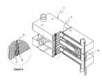
- FIG. 2Thermoelectrics mounted in same plane with cut-away view
- FIG. 2depicts a cut-away view of the multiple thermoelectric modules mounted in the same plane sandwiched between two opposing cold fluidic blocks under spring compression with the heating fluidic block in the center.
- This applicationpertains to removing the need to sort individual components that could consist of multiple elements configured in the same plane as a single system.
- the inherent designallows for the separation of air in the heating and cooling fluidic paths by feeding input fluids from the lowest point of the invention to the highest point of discharge of the invention. Fluid paths are mounted with a pronounced elevation of all exit paths from each element of the heating or cooling blocks. The required elevation is dependant on fluid velocity through the heating and cooling blocks. A base elevation of 15 degrees to 45 degrees from horizontal is the preferred configuration for fluid paths below one inch in diameter.
- thermoelectric modulesMultiple fluids of different temperatures for circulating to and from external storage tanks or reservoirs cycle through opposing blocks of different fluid temperatures generate electricity within the thermoelectric modules.
- Cold blocks numbers 1 and 3are in spring compression around hot block number 7 . Electricity is generated in thermoelectric modules number 10 and number 11 .
- Cold waterenters via number 9 and exits number 12 .
- Hot waterenters via number 8 and exits from number 2 to return to a storage reservoir. The temperature difference between the hot and cold generates electricity.
- By circulating fluid from the low input ports of number 8 and number 9air is transported out of the assembly to the exit ports number 2 for hot fluid and number 12 for cold fluid.
- Each cold blockif bifurcated at number 5 which allows for not having to sort any stack element (thermoelectric modules or hot or cold blocks) for thickness dimensions.
- Cold ports number 4 and number 6show detents for O-rings that allow for stack mechanical tolerance build up to be automatically compensated and removed while providing automatic compensation for thermal expansion and contraction. Any number of elements can be added to the stack by mounting the new element to the fluid input port number 6 and output fluid port number 4 .
- Cold block 3is bifurcated in the middle and has a dog leg feature that keeps adjacent blocks connected and applies pressure on o-ring 13 .
- This featureeliminates multiple in plane sorting of thermoelectric modules and other stack elements.
- O-ring 14also allows dimensional mechanical differences to be automatically adjusted to, eliminating sorting or lapping procedures. Compression on the total stack is shown in the detail ‘A’ enlargement.
- Spring 15is held on to connecting rod 16 under compression, and further held in place by C-ring 17 .
- This embodimentallows all axis expansion, contraction and natural mechanical variance in stack elements in multi-up configurations.
- This viewshows a double opposed two multi-up thermoelectric module configuration. Any number of parallel in plane configurations can be constructed in this manner.
Landscapes
- Heat-Exchange Devices With Radiators And Conduit Assemblies (AREA)
Abstract
Description
Claims (27)
Priority Applications (1)
| Application Number | Priority Date | Filing Date | Title |
|---|---|---|---|
| US10/823,353US8227682B2 (en) | 2003-04-17 | 2004-04-13 | Same plane multiple thermoelectric mounting system |
Applications Claiming Priority (2)
| Application Number | Priority Date | Filing Date | Title |
|---|---|---|---|
| US46353103P | 2003-04-17 | 2003-04-17 | |
| US10/823,353US8227682B2 (en) | 2003-04-17 | 2004-04-13 | Same plane multiple thermoelectric mounting system |
Publications (2)
| Publication Number | Publication Date |
|---|---|
| US20040206386A1 US20040206386A1 (en) | 2004-10-21 |
| US8227682B2true US8227682B2 (en) | 2012-07-24 |
Family
ID=33162336
Family Applications (1)
| Application Number | Title | Priority Date | Filing Date |
|---|---|---|---|
| US10/823,353Expired - Fee RelatedUS8227682B2 (en) | 2003-04-17 | 2004-04-13 | Same plane multiple thermoelectric mounting system |
Country Status (1)
| Country | Link |
|---|---|
| US (1) | US8227682B2 (en) |
Cited By (1)
| Publication number | Priority date | Publication date | Assignee | Title |
|---|---|---|---|---|
| US11167618B2 (en)* | 2015-07-23 | 2021-11-09 | Hyundai Motor Company | Combined heat exchanger module |
Families Citing this family (6)
| Publication number | Priority date | Publication date | Assignee | Title |
|---|---|---|---|---|
| US20030024566A1 (en)* | 2001-07-18 | 2003-02-06 | Watts Phillip Charles | Combination outdoor portable heating pad and electricity generator |
| FR2932924B1 (en)* | 2008-06-24 | 2011-03-04 | Valeo Systemes Thermiques | DEVICE FOR GENERATING ELECTRIC ENERGY, HEAT EXCHANGE BEAM COMPRISING SUCH DEVICE AND HEAT EXCHANGER COMPRISING SUCH BEAM |
| FR2965404B1 (en)* | 2010-09-29 | 2012-09-14 | Valeo Systemes Thermiques | METHOD OF MANUFACTURING A THERMO ELECTRICAL DEVICE, PARTICULARLY FOR GENERATING AN ELECTRICAL CURRENT IN A MOTOR VEHICLE. |
| US20120204923A1 (en)* | 2011-02-15 | 2012-08-16 | Mesa Digital, Llc | Thermoelectric piping apparatus and method for generating electricity |
| FR2972570B1 (en)* | 2011-03-10 | 2016-06-10 | Valeo Systemes Thermiques | MODULE AND ELECTRIC THERMO DEVICE, PARTICULARLY FOR GENERATING AN ELECTRICAL CURRENT IN A MOTOR VEHICLE |
| EP2960953B1 (en)* | 2014-06-25 | 2018-04-11 | Alfa Laval Corporate AB | Plate heat exchanger assembly and a frame to be used in such assembly |
Citations (23)
| Publication number | Priority date | Publication date | Assignee | Title |
|---|---|---|---|---|
| US3240261A (en)* | 1964-12-14 | 1966-03-15 | Robert H Dietrich | Thermoelectric apparatus and method |
| US3607443A (en)* | 1966-09-23 | 1971-09-21 | Nuclear Materials & Equipment | Electrical generator |
| US3607444A (en)* | 1966-12-06 | 1971-09-21 | Siemens Ag | Thermoelectric assembly |
| US3899359A (en) | 1970-07-08 | 1975-08-12 | John Z O Stachurski | Thermoelectric generator |
| US3989547A (en)* | 1971-05-10 | 1976-11-02 | Arco Medical Products Company | Thermoelectric generator having a resiliently mounted removable thermoelectric module |
| US4011104A (en)* | 1973-10-05 | 1977-03-08 | Hughes Aircraft Company | Thermoelectric system |
| US4095998A (en)* | 1976-09-30 | 1978-06-20 | The United States Of America As Represented By The Secretary Of The Army | Thermoelectric voltage generator |
| US4125122A (en)* | 1975-08-11 | 1978-11-14 | Stachurski John Z O | Direct energy conversion device |
| US4564504A (en)* | 1983-11-29 | 1986-01-14 | Sorco Corporation | Apparatus for producing an acid compound |
| US4753682A (en)* | 1985-09-03 | 1988-06-28 | Ital Idee S.R.L. | Apparatus of thermoelectric effect for current generation in internal combustion engine vehicles and the like, with recovery of the externally dissipated heat |
| US4802929A (en) | 1986-12-19 | 1989-02-07 | Fairchild Industries, Inc. | Compliant thermoelectric converter |
| US5228923A (en)* | 1991-12-13 | 1993-07-20 | Implemed, Inc. | Cylindrical thermoelectric cells |
| US5322042A (en)* | 1992-06-17 | 1994-06-21 | Sonex Research, Inc. | Combustion chamber for internal combustion engine and process of combustion using fuel radical species |
| US5450869A (en)* | 1992-03-25 | 1995-09-19 | Volvo Flygmotor Ab | Heater mechanism including a light compact thermoelectric converter |
| US5625245A (en)* | 1993-10-19 | 1997-04-29 | Bass; John C. | Thermoelectric generator for motor vehicle |
| WO1997043790A1 (en) | 1996-05-10 | 1997-11-20 | Tryport International, Gmbh | Improved thermoelectric unit with electric input/output provision |
| US5917144A (en)* | 1996-06-11 | 1999-06-29 | Matsushita Electric Industrial Co., Ltd. | Thermoelectric generator, thermoelectric generator for outdoor use |
| US6385976B1 (en)* | 2000-09-08 | 2002-05-14 | Ferrotec (Usa) Corporation | Thermoelectric module with integrated heat exchanger and method of use |
| US6410971B1 (en)* | 2001-07-12 | 2002-06-25 | Ferrotec (Usa) Corporation | Thermoelectric module with thin film substrates |
| WO2003071198A1 (en) | 2002-02-22 | 2003-08-28 | Varmaraf Ehf. | A heat transfer apparatus |
| US20040068991A1 (en) | 1999-10-07 | 2004-04-15 | Ben Banney | Heat exchanger for an electronic heat pump |
| US6759586B2 (en) | 2001-03-26 | 2004-07-06 | Kabushiki Kaisha Toshiba | Thermoelectric module and heat exchanger |
| US7587902B2 (en) | 2001-02-09 | 2009-09-15 | Bsst, Llc | High power density thermoelectric systems |
- 2004
- 2004-04-13USUS10/823,353patent/US8227682B2/ennot_activeExpired - Fee Related
Patent Citations (23)
| Publication number | Priority date | Publication date | Assignee | Title |
|---|---|---|---|---|
| US3240261A (en)* | 1964-12-14 | 1966-03-15 | Robert H Dietrich | Thermoelectric apparatus and method |
| US3607443A (en)* | 1966-09-23 | 1971-09-21 | Nuclear Materials & Equipment | Electrical generator |
| US3607444A (en)* | 1966-12-06 | 1971-09-21 | Siemens Ag | Thermoelectric assembly |
| US3899359A (en) | 1970-07-08 | 1975-08-12 | John Z O Stachurski | Thermoelectric generator |
| US3989547A (en)* | 1971-05-10 | 1976-11-02 | Arco Medical Products Company | Thermoelectric generator having a resiliently mounted removable thermoelectric module |
| US4011104A (en)* | 1973-10-05 | 1977-03-08 | Hughes Aircraft Company | Thermoelectric system |
| US4125122A (en)* | 1975-08-11 | 1978-11-14 | Stachurski John Z O | Direct energy conversion device |
| US4095998A (en)* | 1976-09-30 | 1978-06-20 | The United States Of America As Represented By The Secretary Of The Army | Thermoelectric voltage generator |
| US4564504A (en)* | 1983-11-29 | 1986-01-14 | Sorco Corporation | Apparatus for producing an acid compound |
| US4753682A (en)* | 1985-09-03 | 1988-06-28 | Ital Idee S.R.L. | Apparatus of thermoelectric effect for current generation in internal combustion engine vehicles and the like, with recovery of the externally dissipated heat |
| US4802929A (en) | 1986-12-19 | 1989-02-07 | Fairchild Industries, Inc. | Compliant thermoelectric converter |
| US5228923A (en)* | 1991-12-13 | 1993-07-20 | Implemed, Inc. | Cylindrical thermoelectric cells |
| US5450869A (en)* | 1992-03-25 | 1995-09-19 | Volvo Flygmotor Ab | Heater mechanism including a light compact thermoelectric converter |
| US5322042A (en)* | 1992-06-17 | 1994-06-21 | Sonex Research, Inc. | Combustion chamber for internal combustion engine and process of combustion using fuel radical species |
| US5625245A (en)* | 1993-10-19 | 1997-04-29 | Bass; John C. | Thermoelectric generator for motor vehicle |
| WO1997043790A1 (en) | 1996-05-10 | 1997-11-20 | Tryport International, Gmbh | Improved thermoelectric unit with electric input/output provision |
| US5917144A (en)* | 1996-06-11 | 1999-06-29 | Matsushita Electric Industrial Co., Ltd. | Thermoelectric generator, thermoelectric generator for outdoor use |
| US20040068991A1 (en) | 1999-10-07 | 2004-04-15 | Ben Banney | Heat exchanger for an electronic heat pump |
| US6385976B1 (en)* | 2000-09-08 | 2002-05-14 | Ferrotec (Usa) Corporation | Thermoelectric module with integrated heat exchanger and method of use |
| US7587902B2 (en) | 2001-02-09 | 2009-09-15 | Bsst, Llc | High power density thermoelectric systems |
| US6759586B2 (en) | 2001-03-26 | 2004-07-06 | Kabushiki Kaisha Toshiba | Thermoelectric module and heat exchanger |
| US6410971B1 (en)* | 2001-07-12 | 2002-06-25 | Ferrotec (Usa) Corporation | Thermoelectric module with thin film substrates |
| WO2003071198A1 (en) | 2002-02-22 | 2003-08-28 | Varmaraf Ehf. | A heat transfer apparatus |
Cited By (1)
| Publication number | Priority date | Publication date | Assignee | Title |
|---|---|---|---|---|
| US11167618B2 (en)* | 2015-07-23 | 2021-11-09 | Hyundai Motor Company | Combined heat exchanger module |
Also Published As
| Publication number | Publication date |
|---|---|
| US20040206386A1 (en) | 2004-10-21 |
Similar Documents
| Publication | Publication Date | Title |
|---|---|---|
| US20130213449A1 (en) | Thermoelectric plate and frame exchanger | |
| JP4580422B2 (en) | Micro component sheet structure | |
| US6748755B2 (en) | Refrigeration system utilizing incomplete evaporation of refrigerant in evaporator | |
| US7032651B2 (en) | Heat exchanger | |
| US8196480B1 (en) | Modular sample conditioning system | |
| EP0212878A1 (en) | Plate-type cross-flow heat exchanger | |
| WO2018097092A1 (en) | Electricity storage device | |
| US8227682B2 (en) | Same plane multiple thermoelectric mounting system | |
| CN117751270A (en) | Modular fluid heat exchange system | |
| GB2227123A (en) | Cooling electronic circuit boards | |
| CA2733847C (en) | Heat exchanger | |
| TW200727121A (en) | Multi-element heat exchange assemblies and methods of fabrication for a cooling system | |
| US8925623B2 (en) | Scaleable parallel flow micro-channel heat exchanger and method for manufacturing same | |
| EP3499169A1 (en) | Laminated header, heat exchanger and refrigeration cycle device | |
| ATE434832T1 (en) | MICROELECTRONIC SYSTEM WITH INTEGRATED CRYOSTATIC COOLER | |
| EP3097374A1 (en) | Heat exchanger | |
| CN114502899A (en) | Solid Cooling Module | |
| US10193048B2 (en) | Energy recovering assembly and a method of providing the same | |
| JP7704840B2 (en) | heat exchanger | |
| KR101307518B1 (en) | Thermoelectric generator device | |
| WO2022022759A1 (en) | Heat exchanger assembly | |
| EP3312530A1 (en) | Heat exchange device | |
| CN116075119A (en) | Refrigerant cooling heat sink for power electronics modules | |
| KR102523184B1 (en) | Printed circuit type heat exchanger | |
| US7752928B1 (en) | Modular sample conditioning system |
Legal Events
| Date | Code | Title | Description |
|---|---|---|---|
| AS | Assignment | Owner name:WATTS THERMOELECTRIC, LLC, COLORADO Free format text:ASSIGNMENT OF ASSIGNORS INTEREST;ASSIGNOR:WATTS, PHILLIP CHARLES;REEL/FRAME:023249/0212 Effective date:20090710 | |
| STCF | Information on status: patent grant | Free format text:PATENTED CASE | |
| REMI | Maintenance fee reminder mailed | ||
| FPAY | Fee payment | Year of fee payment:4 | |
| SULP | Surcharge for late payment | ||
| AS | Assignment | Owner name:WATTS, DENESE G., MS, COLORADO Free format text:ASSIGNMENT OF ASSIGNORS INTEREST;ASSIGNOR:PHILLIP CHARLES WATTS, DECEASED BY JENNIFER GAYLE FINLEY, EXECUTOR OF ESTATE;REEL/FRAME:051796/0366 Effective date:20190524 | |
| FEPP | Fee payment procedure | Free format text:MAINTENANCE FEE REMINDER MAILED (ORIGINAL EVENT CODE: REM.); ENTITY STATUS OF PATENT OWNER: SMALL ENTITY | |
| FEPP | Fee payment procedure | Free format text:7.5 YR SURCHARGE - LATE PMT W/IN 6 MO, SMALL ENTITY (ORIGINAL EVENT CODE: M2555); ENTITY STATUS OF PATENT OWNER: SMALL ENTITY | |
| MAFP | Maintenance fee payment | Free format text:PAYMENT OF MAINTENANCE FEE, 8TH YR, SMALL ENTITY (ORIGINAL EVENT CODE: M2552); ENTITY STATUS OF PATENT OWNER: SMALL ENTITY Year of fee payment:8 | |
| AS | Assignment | Owner name:BAUMAN, STEVEN, MR, NEW MEXICO Free format text:ASSIGNMENT OF ASSIGNORS INTEREST;ASSIGNOR:WATTS, DENESE G, MS;REEL/FRAME:056012/0695 Effective date:20201019 | |
| FEPP | Fee payment procedure | Free format text:MAINTENANCE FEE REMINDER MAILED (ORIGINAL EVENT CODE: REM.); ENTITY STATUS OF PATENT OWNER: SMALL ENTITY | |
| LAPS | Lapse for failure to pay maintenance fees | Free format text:PATENT EXPIRED FOR FAILURE TO PAY MAINTENANCE FEES (ORIGINAL EVENT CODE: EXP.); ENTITY STATUS OF PATENT OWNER: SMALL ENTITY | |
| STCH | Information on status: patent discontinuation | Free format text:PATENT EXPIRED DUE TO NONPAYMENT OF MAINTENANCE FEES UNDER 37 CFR 1.362 | |
| FP | Lapsed due to failure to pay maintenance fee | Effective date:20240724 |