US8226720B2 - Disk augmentation system - Google Patents
Disk augmentation systemDownload PDFInfo
- Publication number
- US8226720B2 US8226720B2US11/869,009US86900907AUS8226720B2US 8226720 B2US8226720 B2US 8226720B2US 86900907 AUS86900907 AUS 86900907AUS 8226720 B2US8226720 B2US 8226720B2
- Authority
- US
- United States
- Prior art keywords
- recited
- compression system
- adjustable
- disk
- adjustable compression
- Prior art date
- Legal status (The legal status is an assumption and is not a legal conclusion. Google has not performed a legal analysis and makes no representation as to the accuracy of the status listed.)
- Active, expires
Links
- 230000003416augmentationEffects0.000titleclaimsabstractdescription14
- 230000006835compressionEffects0.000claimsabstractdescription129
- 238000007906compressionMethods0.000claimsabstractdescription129
- 230000008878couplingEffects0.000claimsdescription4
- 238000010168coupling processMethods0.000claimsdescription4
- 238000005859coupling reactionMethods0.000claimsdescription4
- 239000000463materialSubstances0.000claimsdescription3
- 239000004698PolyethyleneSubstances0.000claimsdescription2
- -1polyethylenePolymers0.000claimsdescription2
- 229920000573polyethylenePolymers0.000claimsdescription2
- 229920000642polymerPolymers0.000claimsdescription2
- 229920001296polysiloxanePolymers0.000claimsdescription2
- 230000001154acute effectEffects0.000claims2
- 238000000034methodMethods0.000description20
- 230000008901benefitEffects0.000description3
- 230000007246mechanismEffects0.000description3
- 230000008569processEffects0.000description2
- 238000001356surgical procedureMethods0.000description2
- 210000002517zygapophyseal jointAnatomy0.000description2
- 208000027418Wounds and injuryDiseases0.000description1
- 210000001015abdomenAnatomy0.000description1
- 230000003187abdominal effectEffects0.000description1
- 238000005452bendingMethods0.000description1
- 230000000295complement effectEffects0.000description1
- 230000006378damageEffects0.000description1
- 230000000694effectsEffects0.000description1
- 239000012530fluidSubstances0.000description1
- 208000014674injuryDiseases0.000description1
- 230000036316preloadEffects0.000description1
- 239000012858resilient materialSubstances0.000description1
- 230000004044responseEffects0.000description1
- 238000010561standard procedureMethods0.000description1
- 208000011580syndromic diseaseDiseases0.000description1
Images


Classifications
- A—HUMAN NECESSITIES
- A61—MEDICAL OR VETERINARY SCIENCE; HYGIENE
- A61B—DIAGNOSIS; SURGERY; IDENTIFICATION
- A61B17/00—Surgical instruments, devices or methods
- A61B17/56—Surgical instruments or methods for treatment of bones or joints; Devices specially adapted therefor
- A61B17/58—Surgical instruments or methods for treatment of bones or joints; Devices specially adapted therefor for osteosynthesis, e.g. bone plates, screws or setting implements
- A61B17/68—Internal fixation devices, including fasteners and spinal fixators, even if a part thereof projects from the skin
- A61B17/70—Spinal positioners or stabilisers, e.g. stabilisers comprising fluid filler in an implant
- A61B17/7001—Screws or hooks combined with longitudinal elements which do not contact vertebrae
- A61B17/7043—Screws or hooks combined with longitudinal elements which do not contact vertebrae with a longitudinal element fixed to one or more transverse elements which connect multiple screws or hooks
- A—HUMAN NECESSITIES
- A61—MEDICAL OR VETERINARY SCIENCE; HYGIENE
- A61B—DIAGNOSIS; SURGERY; IDENTIFICATION
- A61B17/00—Surgical instruments, devices or methods
- A61B17/56—Surgical instruments or methods for treatment of bones or joints; Devices specially adapted therefor
- A61B17/58—Surgical instruments or methods for treatment of bones or joints; Devices specially adapted therefor for osteosynthesis, e.g. bone plates, screws or setting implements
- A61B17/68—Internal fixation devices, including fasteners and spinal fixators, even if a part thereof projects from the skin
- A61B17/70—Spinal positioners or stabilisers, e.g. stabilisers comprising fluid filler in an implant
- A61B17/7001—Screws or hooks combined with longitudinal elements which do not contact vertebrae
- A61B17/7002—Longitudinal elements, e.g. rods
- A61B17/7019—Longitudinal elements having flexible parts, or parts connected together, such that after implantation the elements can move relative to each other
- A61B17/7031—Longitudinal elements having flexible parts, or parts connected together, such that after implantation the elements can move relative to each other made wholly or partly of flexible material
- A—HUMAN NECESSITIES
- A61—MEDICAL OR VETERINARY SCIENCE; HYGIENE
- A61B—DIAGNOSIS; SURGERY; IDENTIFICATION
- A61B17/00—Surgical instruments, devices or methods
- A61B17/56—Surgical instruments or methods for treatment of bones or joints; Devices specially adapted therefor
- A61B17/58—Surgical instruments or methods for treatment of bones or joints; Devices specially adapted therefor for osteosynthesis, e.g. bone plates, screws or setting implements
- A61B17/68—Internal fixation devices, including fasteners and spinal fixators, even if a part thereof projects from the skin
- A61B17/70—Spinal positioners or stabilisers, e.g. stabilisers comprising fluid filler in an implant
- A61B17/7049—Connectors, not bearing on the vertebrae, for linking longitudinal elements together
- A—HUMAN NECESSITIES
- A61—MEDICAL OR VETERINARY SCIENCE; HYGIENE
- A61F—FILTERS IMPLANTABLE INTO BLOOD VESSELS; PROSTHESES; DEVICES PROVIDING PATENCY TO, OR PREVENTING COLLAPSING OF, TUBULAR STRUCTURES OF THE BODY, e.g. STENTS; ORTHOPAEDIC, NURSING OR CONTRACEPTIVE DEVICES; FOMENTATION; TREATMENT OR PROTECTION OF EYES OR EARS; BANDAGES, DRESSINGS OR ABSORBENT PADS; FIRST-AID KITS
- A61F2/00—Filters implantable into blood vessels; Prostheses, i.e. artificial substitutes or replacements for parts of the body; Appliances for connecting them with the body; Devices providing patency to, or preventing collapsing of, tubular structures of the body, e.g. stents
- A61F2/02—Prostheses implantable into the body
- A61F2/30—Joints
- A61F2/44—Joints for the spine, e.g. vertebrae, spinal discs
- A61F2/4405—Joints for the spine, e.g. vertebrae, spinal discs for apophyseal or facet joints, i.e. between adjacent spinous or transverse processes
- A—HUMAN NECESSITIES
- A61—MEDICAL OR VETERINARY SCIENCE; HYGIENE
- A61F—FILTERS IMPLANTABLE INTO BLOOD VESSELS; PROSTHESES; DEVICES PROVIDING PATENCY TO, OR PREVENTING COLLAPSING OF, TUBULAR STRUCTURES OF THE BODY, e.g. STENTS; ORTHOPAEDIC, NURSING OR CONTRACEPTIVE DEVICES; FOMENTATION; TREATMENT OR PROTECTION OF EYES OR EARS; BANDAGES, DRESSINGS OR ABSORBENT PADS; FIRST-AID KITS
- A61F2/00—Filters implantable into blood vessels; Prostheses, i.e. artificial substitutes or replacements for parts of the body; Appliances for connecting them with the body; Devices providing patency to, or preventing collapsing of, tubular structures of the body, e.g. stents
- A61F2/02—Prostheses implantable into the body
- A61F2/30—Joints
- A61F2002/30001—Additional features of subject-matter classified in A61F2/28, A61F2/30 and subgroups thereof
- A61F2002/30316—The prosthesis having different structural features at different locations within the same prosthesis; Connections between prosthetic parts; Special structural features of bone or joint prostheses not otherwise provided for
- A61F2002/30535—Special structural features of bone or joint prostheses not otherwise provided for
- A61F2002/30563—Special structural features of bone or joint prostheses not otherwise provided for having elastic means or damping means, different from springs, e.g. including an elastomeric core or shock absorbers
Definitions
- This inventionrelates to a disk augmentation system and method for providing support for reducing load on one or more disks in a patient's spine.
- Human spinesare formed from vertebrae, which are separated and cushioned from each other by disks.
- the disksconsist of a fibrous outer envelope containing a gel-like fluid.
- the disksare subject to large forces, which may vary from about 175 pounds when a person is at rest to as high as about 500 pounds during activity. For example, a person who lifts a 15-pound weight one foot in front of such person, using a bending movement, can generate nearly 500 pounds of force on his or her spine. Because of the high forces on them, spinal disks commonly rupture, particularly as they deteriorate with age.
- an object of the inventionto provide a disk augmentation system for providing exterior support to one or more vertebrae and to facilitate reducing load on one or more disks.
- this inventioncomprises a disk augmentation system comprising: a first support for mounting onto a first vertebra in a spinal column, a second support for mounting onto a second vertebra, the first and second supports being located exterior to a disk area between the first and second vertebrae and cooperating to define a compression body area for receiving a compression body, the first and second supports supporting the compression body exterior to the disk area and permitting the first and second supports to become non-parallel during compression of the compression body, or wherein the disk augmentation system further comprises an adjustable tensioner that is adjustable after the first support is mounted to the first vertebra and the second support is mounted to the second vertebra, and wherein the compression body is generally planar.
- this inventioncomprises an adjustable compression system for mounting to a plurality of vertebrae, a support for mounting on the vertebrae of a spinal column, and a retainer situated exterior of the spinal column for retaining a compression body outside a native disk space and an axis of the spine, the retainer facilitating reducing loading of at least one disk in the spinal column, the retainer comprising a first support for mounting to a first one of the vertebrae and a second support for mounting to a second one of the vertebrae, the first and second supports being adapted to permit the compression body to replicate or augment a function of a native or natural intervertebral disk by permitting the first support and the second support to become non-parallel relative to each other during use, and an adjustable tensioner for adjusting an amount of compression on the compression body between the first support and the second support after the first and second supports are mounted onto the first one of the vertebrae and the second one of the vertebrae, respectively, wherein the compression body is generally planar.
- this inventioncomprises a method for reducing load on a disk, mounting a first support on a first vertebra, mounting a second support on a second vertebra that is adjacent the first vertebra, the first and second supports defining an area for housing a compression body exterior to a disk area, and situating the compression body in the area, using an adjustor to adjust an amount of loading on the compression body after the first and second supports are mounted on the first and second vertebrae, respectively, the adjustor adjustably coupling the first support to the second support, and the first and second supports being adapted to become non-parallel during compression of the compression body.
- this inventioncomprises an adjustable compression system for reducing a load on at least one lumbar disk in a spinal column
- the adjustable compression systemcomprising: a retainer for mounting on a first vertebra and a second vertebra of a spinal column, the retainer comprising a first artificial body support and a second artificial body support cooperating to define a retaining area for receiving an artificial body and for supporting the artificial body posterior of the first vertebra and the second vertebra, an adjuster adjusting an amount of loading on the artificial body after the first and second supports are mounted on the first and second ones, respectively, of the vertebrae; and the retainer cooperating with the artificial body to facilitate reducing load on the at least one lumbar disk when the first and second vertebrae move either toward or away from each other, and permitting the first artificial body support and the second artificial body support to become non-parallel relative to each other to replicate or augment a function of a native disk, the artificial body being generally planar.
- this inventioncomprises an extra-axial spinal artificial disk method comprising the step of placing an artificial elastic or articulating mechanism that replicates or augments the function of a native disk in any location other than a native disk space or a normal axis of the spine.
- this inventioncomprises an artificial disk that replicates or augments the function of a native disk in any location other than a native disk space or a normal axis of the spine, comprising: a body, and an elastomeric or articulating mechanism in the body.
- this inventioncomprises an adjustable compression system for reducing the load on at least one lumbar disk, the adjustable compression system comprising: a retainer for retaining a first compression body posterior of the spinal column and for facilitating reducing load on at least one lumbar disk in the spinal column, and a second retainer for mounting on the spinal column also for facilitating reducing load on the at least one lumbar disk, wherein the first and second retainers are not located along an axis of the spinal column.
- FIG. 1is a view of a showing a disk situated between adjacent vertebrae.
- FIG. 2is another view with part of the central vertebrae removed
- FIG. 3is a view illustrating means and method for mounting support rods onto anchor screws
- FIG. 4is a view illustrating a retainer mounted onto the support rods
- FIG. 5is an exploded view of the retainer shown in a mounted position in FIG. 4 ;
- FIG. 6is a sectional view illustrating a single disk being used with a pair of support members
- FIG. 7illustrates another feature of the invention used without a disk
- FIG. 8illustrates a supply of compression bodies or disks of varying densities and sizes
- FIG. 9is an exploded view of an embodiment of the inventions.
- FIG. 10is a rear view of a rear or posterior view of the retainer mounted on the supports;
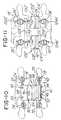
- FIG. 11is a view of another embodiment of the invention showing a plurality of retainers mounted on supports;
- FIG. 12is another view of another embodiment.
- FIG. 13is a view of a pair of supports used in another embodiment of the invention.
- the system and method of the inventionare used to facilitate reducing load on one or more disks, such as disk 12 between vertebrae 14 and 16 and disk 18 between vertebrae 16 and 20 .
- the inventioncomprises means or a system 22 for reducing a load on at least one of lumbar disks when the vertebrae, such as vertebrae 14 and 16 , move either away from or toward each other.
- the system 22comprises a plurality of screws 24 , 26 , 28 and 30 comprising open heads 24 a , 26 a , 28 a and 30 a , respectively.
- the open heads 24 a , 26 a , 28 a and 30 acomprise a receiving area 24 a 1 , 26 a 1 , 28 a 1 and 30 a 1 , respectively.
- the areas 24 a 1 , 26 a 1 , 28 a 1 and 30 a 1receive supports 32 and 42 as shown.
- the open heads 24 a and 26 areceive a support or cylindrical rod 32 in the areas 24 a 1 and 26 a 1 , respectively.
- the inner diameter of the heads 24 a , 26 a , 28 a and 30 aare threaded to threadably receive the screws 34 , 36 , 38 and 40 as described later herein.
- the screws 24 , 26 , 28 and 30are first screwed into the vertebrae 16 and 20 .
- the support 32is situated in the areas 24 a 1 and 26 a 1 .
- the heads 24 a and 26 areceive the screws 34 and 36 to secure the support 32 to the heads 24 a and 26 a as shown.
- the support 42is situated in the areas 28 a 1 and 30 a 1 .
- the screws 38 and 40are threadably received in the threaded screw heads 28 a and 30 a to lock the support 42 to the heads 28 a and 30 a.
- the system 22further comprises at least one retainer, retainer means or retaining system 41 ( FIG. 5 ) for mounting on the supports 32 and 42 to supportably retain at least one compression body, such as a compression disk 64 , exterior of an axis of the patient's spine.
- the retainer 41comprises a first support 44 and a second support 46 which are mounted onto the rods 32 and 42 , respectively, with appropriate fasteners or screws 48 , 50 , 52 and 54 , as best illustrated in FIG. 10 .
- a third support 56may optionally be provided as well.
- system 22comprises an adjustable fastener or fastening means in the form of an adjustable fastener, tensioner or screw 58 that is received through the apertures 56 a and 44 a of supports 56 and 44 and threadably received in a threaded opening 46 a of support 46 .
- the support 44comprises an aperture or recessed area 70 ( FIG. 5 ) defined by a generally arcuate or curved wall 72 .
- the support 32is received in the area 70 and the screws 48 and 50 ( FIG. 9 ) are threadably mounted in the threaded openings 51 and 53 , respectively.
- the ends 48 a and 50 a of screws 48 and 50engage the support 32 and force it against the surface 72 a ( FIG. 5 ) in order to mount and retain the support 44 on the rod 32 .
- the support 46comprises an aperture 74 defined by an arcuate or curved wall 76 and having a surface 76 a against which the support or rod 42 engages when the second support 46 is mounted thereto. In this regard and as illustrated in FIGS.
- screws 52 and 54are threadably received in threaded openings (e.g. threaded screw 52 is received in opening 78 in FIG. 9 ) until end 52 a of screw 52 engages the support 42 and forces it against the surface 76 a , thereby mounting and retaining the second support 46 onto the support 42
- the supports 44 and 46cooperate to define a first compression body area 60
- supports 44 and 56cooperate to define a second compression body area 62
- the first and second compression body areas 60 and 62receive at least one compression body, such as compression bodies or disks 64 and 66 , respectively.
- the compression bodyis a compressible material such as polyethylene, silicone, or viscoelastic polymer that comprises a mechanical density on the order of the native intervertebral disk.
- the compression bodies 64 and 66may comprise any suitable cross-sectional and overall shape, such as one or more of the polygonal shapes illustrated in FIG. 8 or any oval, elliptical, circular or any other suitable or desired shape to provide the desired compression characteristics necessary to facilitate relieving or reducing load on at least one of the disks 12 or 18 ( FIG. 1 ).
- the inventionmay be used with less than all three of the supports 44 , 46 , and 56 or with more supports as desired in a stacked or sandwiched array of supports and compression bodies, one on top of the other.
- the system 22could comprise just a pair of supports 44 and 46 between which one or more disks are mounted as shown in FIG. 6 .
- the supportscould be provided without any compression disk therebetween to provide a fixed or fusion-type support to the vertebrae, such as vertebrae 16 and 20 illustrated in FIG. 4 .
- the first and second supports 44 and 46comprise portions 44 b and 46 b that lie in imaginary planes P 1 and P 2 ( FIG. 4 ) that are generally parallel and are situated at an angle ⁇ relative to the spinal axis when the system 22 is assembled and mounted into position illustrated in FIG. 4 .
- the compression bodies 64 and 66lie in one or more planes, such as planes P 1 and P 2 , as illustrated in FIG. 4 .
- the angle ⁇is a predetermined angle of approximately 30 degrees or less. The angle generally corresponds to the angle between the long axis of the spine and the facet joints and/or spinous processes.
- the compression bodies 64 and 66are situated exterior to the spinal axis and spinal column, as illustrated in FIG. 4 .
- the planes P 1 and P 2 mentioned earlierare generally parallel to the facet joint and inter-spinous process articulations.
- the at least one adjustable fastener 58is adjustable to permit loading at least one of the compression bodies 64 and 66 with a predetermined amount of pressure.
- the predetermined amount of pressureis about 10-300 pounds. The predetermined amount of pressure may vary depending on the desired compliance and constraining properties of the device.
- the supports 44 , 46 and 56each comprise a compression body support surface which in the embodiment being described is a planar portion 44 b , 46 b and 56 b .
- Each of the generally planar portions 44 b , 46 b and 56 bare arranged to define opposing surfaces 44 b 1 and 44 b 2 , 46 b 1 and 46 b 2 , and 56 b 1 and 56 b 2 , respectively.
- Each surfacecooperates with an opposing surface from an adjacent support to define the compression body receiving areas, such as the areas 60 and 62 ( FIG. 5 ), mentioned earlier herein.
- the support 44 in FIG. 5comprises the surfaces 44 b 1 and 44 b 2 .
- the surface 44 b 2 of support 44cooperates with surface 56 b 1 of planar portion 56 b to define the compression body receiving area 62 .
- the surface 44 b 1 of support 44cooperates with surface 46 b 1 to define the compression body receiving area 60 .
- the surfaces 44 b 1 , 44 b 2 , 46 b 1 , 46 b 2 , 56 b 1 and 56 b 2may define a substantially continuous or flat surface for supporting all or a portion of the compression bodies 64 and 66 , which as mentioned earlier, may be provided in any suitable shape. Alternatively, these surfaces may be non-planar.
- the surfacesmay be concave or define a recessed area (not shown) that generally corresponds to the shape of the compression body to facilitate retaining the compression body in place.
- the compression bodieshave an aperture, such as aperture 66 a in body 66 , that receives the adjustable fastener 58 to facilitate retaining the body in place.
- system and method of the present inventionprovide means for situating one or more artificial compression bodies exterior to the spinal column and exterior to the disk areas in which the patient's disks, such as disks 12 and 18 , are situated.
- the compression bodies 64 and 66are selected from a supply of a plurality of compression bodies comprising a plurality of different predetermined densities and/or a plurality of different predetermined shapes when viewed in cross section and/or a plan view.
- the compression bodies 64 , 66 and 81 - 91 in FIG. 8may comprise a cross-sectional and overall shape that is polygonal, triangular, elliptical, circular, rectangular, square, or any other suitable shape desired.
- the compression bodiessuch as compression bodies 64 and 66 shown in FIG. 9
- the compression bodies 64 and 66 shown in FIG. 9may be generally rectangular to match or generally correspond to or complement the shape and size of the planar surfaces 44 b 1 , 44 b 2 , 46 b 1 and 56 b 2 .
- different shapes and sizessuch as circular, triangular, polygonal, elliptical shaped disks may be provided.
- the supports 44 , 46 and 56may be provided to define surface areas that are different from the shape of the portions 44 b , 46 b and 56 b illustrated in FIG. 9 .
- a portion 16 a ( FIG. 1 ) of vertebra 16is removed by conventional means. Screws 24 , 26 , 28 and 30 are mounted into the vertebrae, such as vertebrae 16 and 20 in the illustration shown in FIG. 4 .
- the supports 32 and 42are then mounted on the screws 24 - 30 as shown and as described earlier.
- the retainer 41comprising the first and second supports 44 and 46 are then mounted on the support rods 32 and 42 , respectively.
- the disks 64 and 66are sandwiched between the supports 44 , 46 and 56 as shown and the adjustable tensioner 58 is mounted through the disks 64 , 66 and supports 44 and 56 and threaded into threaded aperture 46 a as illustrated in FIGS. 4 and 9 .
- the adjustable fastener 58is adjustable so that a surgeon may preload or load one or more of the compression bodies 62 and 64 with a predetermined amount of pressure by simply rotating the fastener 58 in a clockwise direction. This may be desirable in order to decrease the freedom of movement of the device and decrease the compliance of the compression body based on the patient's needs.
- the retainer 41is situated posterior of and exterior to the spinal axis and the native disk spaces in which the disks, such as disks 12 and 18 in FIG. 1 , are located.
- the system and methodprovide means and apparatus for situating one or more elastic or articulating mechanisms or bodies designed to replicate or augment the function of the native disk in any location other than the native disk space in which the patient's native disk is located.
- the system and methodfurther permits the retainer 41 to be situated outside the axis of the spine.
- Another advantage of the apparatus and system of the inventionis that after the supports 44 and 46 are installed during a first operation, for example, a surgeon may replace the compressible disks, such as disk 64 and 66 , with one or more new or replacement disks 64 and 66 , such as a replacement disk (not shown) having a greater thickness, different density, different shape, different size or the like.
- the system and method of the present inventionis adaptable and enables, for example, a surgeon to replace one or more of the compression bodies 64 and 66 with a replacement body (not shown) during subsequent operations. This can be done by using the same or a different retainer 41 in order to meet the needs of the patient.
- FIGS. 11-13another embodiment of the invention is shown wherein the system and method comprises a plurality of disk augmentation supports for facilitating reducing a load on at least one of the lumbar disks, when the vertebrae, such as vertebrae 14 and 16 ( FIG. 1 ) move either away from or toward each other.
- This embodimentcomprises parts that are the same or similar to the parts shown in FIGS. 1-10 and such parts are labeled with the same part number, except that the parts in FIGS. 11-13 have a prime mark (“′”) added thereto. Notice in the embodiment shown in FIGS. 11-13 that a plurality of retainers 100 ′ are provided.
- Each retainer 100 ′comprises a first support 102 a ′ that is coupled to a support column or post 102 b ′.
- An opposing support 104 ′comprises a planar member 104 a ′ that is coupled to a support post or column 104 b ′. Notice that the surfaces 102 a 1 ′ and 104 a 1 ′ are generally planar in the embodiment being described and support the compression disks 66 ′ as shown. Similar to the embodiment shown in FIGS. 1-10 , the supports 102 b ′ and 104 b ′ are secured to the screws 24 ′- 30 ′ with the screws 34 ′- 40 ′ in the same manner as the embodiment shown in FIGS. 1-10 . The embodiment in FIGS.
- 11-13further comprises a pair of retaining or spacing brackets 106 ′ and 108 ′ that are secured to the supports 102 b ′ and 104 b ′ with the screws 110 ′ and 112 ′, respectively.
- the brackets 106 ′ and 108 ′facilitate retaining the retainers 100 ′ in a fixed and spaced position relative to each other.
- the supports 102 ′ and 104 ′ of retainer 100 ′are secured thereto with the screws 34 ′- 40 ′.
- the compression bodies 66 ′are then placed between surfaces 102 a 1 ′ and 104 a 1 ′ as shown and screw 58 ′ is threaded through opening 107 ′ ( FIG. 13 ) and then threaded into the threaded aperture 109 ′ to retain the compression body 66 between the supports 102 ′ and 104 ′.
- this embodiment of the inventionutilizes the same or similar features as the embodiment illustrated in FIGS. 1-10 to facilitate reducing load on one or more disks in the spine or spinal column.
- the retainers 100 ′may be equipped with multiple disks like in FIG. 4 , and those disks may be configured as shown in FIG. 8 .
- a plurality of retainers 41are provided to provide multiple support to adjacent vertebrae.
- the inventionmay also be used in an environment where one or more disks are fused together, such as when a patient has transitional segment syndrome.
Landscapes
- Health & Medical Sciences (AREA)
- Orthopedic Medicine & Surgery (AREA)
- Life Sciences & Earth Sciences (AREA)
- Neurology (AREA)
- Surgery (AREA)
- Heart & Thoracic Surgery (AREA)
- Engineering & Computer Science (AREA)
- Biomedical Technology (AREA)
- Nuclear Medicine, Radiotherapy & Molecular Imaging (AREA)
- Medical Informatics (AREA)
- Molecular Biology (AREA)
- Animal Behavior & Ethology (AREA)
- General Health & Medical Sciences (AREA)
- Public Health (AREA)
- Veterinary Medicine (AREA)
- Prostheses (AREA)
- Surgical Instruments (AREA)
Abstract
Description
Claims (36)
Priority Applications (1)
| Application Number | Priority Date | Filing Date | Title |
|---|---|---|---|
| US11/869,009US8226720B2 (en) | 2004-04-09 | 2007-10-09 | Disk augmentation system |
Applications Claiming Priority (2)
| Application Number | Priority Date | Filing Date | Title |
|---|---|---|---|
| US10/821,823US7282065B2 (en) | 2004-04-09 | 2004-04-09 | Disk augmentation system and method |
| US11/869,009US8226720B2 (en) | 2004-04-09 | 2007-10-09 | Disk augmentation system |
Related Parent Applications (1)
| Application Number | Title | Priority Date | Filing Date |
|---|---|---|---|
| US10/821,823DivisionUS7282065B2 (en) | 2004-04-09 | 2004-04-09 | Disk augmentation system and method |
Publications (2)
| Publication Number | Publication Date |
|---|---|
| US20080027549A1 US20080027549A1 (en) | 2008-01-31 |
| US8226720B2true US8226720B2 (en) | 2012-07-24 |
Family
ID=35061550
Family Applications (2)
| Application Number | Title | Priority Date | Filing Date |
|---|---|---|---|
| US10/821,823Expired - LifetimeUS7282065B2 (en) | 2004-04-09 | 2004-04-09 | Disk augmentation system and method |
| US11/869,009Active2027-01-29US8226720B2 (en) | 2004-04-09 | 2007-10-09 | Disk augmentation system |
Family Applications Before (1)
| Application Number | Title | Priority Date | Filing Date |
|---|---|---|---|
| US10/821,823Expired - LifetimeUS7282065B2 (en) | 2004-04-09 | 2004-04-09 | Disk augmentation system and method |
Country Status (3)
| Country | Link |
|---|---|
| US (2) | US7282065B2 (en) |
| EP (1) | EP1732458B1 (en) |
| WO (1) | WO2005099392A2 (en) |
Families Citing this family (100)
| Publication number | Priority date | Publication date | Assignee | Title |
|---|---|---|---|---|
| GB0107708D0 (en) | 2001-03-28 | 2001-05-16 | Imp College Innovations Ltd | Bone fixated,articulated joint load control device |
| US20040054414A1 (en) | 2002-09-18 | 2004-03-18 | Trieu Hai H. | Collagen-based materials and methods for augmenting intervertebral discs |
| US7744651B2 (en) | 2002-09-18 | 2010-06-29 | Warsaw Orthopedic, Inc | Compositions and methods for treating intervertebral discs with collagen-based materials |
| JP2006515765A (en) | 2002-11-15 | 2006-06-08 | エスディージーアイ・ホールディングス・インコーポレーテッド | Collagen-based materials and methods for treating synovial joints |
| US8979900B2 (en) | 2003-09-24 | 2015-03-17 | DePuy Synthes Products, LLC | Spinal stabilization device |
| US7815665B2 (en) | 2003-09-24 | 2010-10-19 | N Spine, Inc. | Adjustable spinal stabilization system |
| US7137985B2 (en) | 2003-09-24 | 2006-11-21 | N Spine, Inc. | Marking and guidance method and system for flexible fixation of a spine |
| US20050203513A1 (en) | 2003-09-24 | 2005-09-15 | Tae-Ahn Jahng | Spinal stabilization device |
| US7763052B2 (en) | 2003-12-05 | 2010-07-27 | N Spine, Inc. | Method and apparatus for flexible fixation of a spine |
| US7588590B2 (en) | 2003-12-10 | 2009-09-15 | Facet Solutions, Inc | Spinal facet implant with spherical implant apposition surface and bone bed and methods of use |
| US7771479B2 (en) | 2004-01-09 | 2010-08-10 | Warsaw Orthopedic, Inc. | Dual articulating spinal device and method |
| US20050171608A1 (en) | 2004-01-09 | 2005-08-04 | Sdgi Holdings, Inc. | Centrally articulating spinal device and method |
| US8333789B2 (en) | 2007-01-10 | 2012-12-18 | Gmedelaware 2 Llc | Facet joint replacement |
| US8562649B2 (en) | 2004-02-17 | 2013-10-22 | Gmedelaware 2 Llc | System and method for multiple level facet joint arthroplasty and fusion |
| US9451990B2 (en)* | 2004-02-17 | 2016-09-27 | Globus Medical, Inc. | Facet joint replacement instruments and methods |
| US8480742B2 (en)* | 2005-08-02 | 2013-07-09 | Perumala Corporation | Total artificial disc |
| US7507242B2 (en)* | 2004-06-02 | 2009-03-24 | Facet Solutions | Surgical measurement and resection framework |
| US7481840B2 (en)* | 2004-09-29 | 2009-01-27 | Kyphon Sarl | Multi-piece artificial spinal disk replacement device with selectably positioning articulating element |
| US7896906B2 (en) | 2004-12-30 | 2011-03-01 | Depuy Spine, Inc. | Artificial facet joint |
| US8092496B2 (en) | 2004-09-30 | 2012-01-10 | Depuy Spine, Inc. | Methods and devices for posterior stabilization |
| US20060084976A1 (en) | 2004-09-30 | 2006-04-20 | Depuy Spine, Inc. | Posterior stabilization systems and methods |
| US7766940B2 (en)* | 2004-12-30 | 2010-08-03 | Depuy Spine, Inc. | Posterior stabilization system |
| DE102004048938B4 (en) | 2004-10-07 | 2015-04-02 | Synthes Gmbh | Device for the dynamic stabilization of vertebral bodies |
| US20060085076A1 (en) | 2004-10-15 | 2006-04-20 | Manoj Krishna | Posterior spinal arthroplasty-development of a new posteriorly inserted artificial disc and an artificial facet joint |
| US7935134B2 (en) | 2004-10-20 | 2011-05-03 | Exactech, Inc. | Systems and methods for stabilization of bone structures |
| US8226690B2 (en) | 2005-07-22 | 2012-07-24 | The Board Of Trustees Of The Leland Stanford Junior University | Systems and methods for stabilization of bone structures |
| US8025680B2 (en) | 2004-10-20 | 2011-09-27 | Exactech, Inc. | Systems and methods for posterior dynamic stabilization of the spine |
| US8162985B2 (en) | 2004-10-20 | 2012-04-24 | The Board Of Trustees Of The Leland Stanford Junior University | Systems and methods for posterior dynamic stabilization of the spine |
| US8267969B2 (en) | 2004-10-20 | 2012-09-18 | Exactech, Inc. | Screw systems and methods for use in stabilization of bone structures |
| US20060265074A1 (en)* | 2004-10-21 | 2006-11-23 | Manoj Krishna | Posterior spinal arthroplasty-development of a new posteriorly inserted artificial disc, a new anteriorly inserted artifical disc and an artificial facet joint |
| WO2006058221A2 (en) | 2004-11-24 | 2006-06-01 | Abdou Samy M | Devices and methods for inter-vertebral orthopedic device placement |
| US8597331B2 (en)* | 2004-12-10 | 2013-12-03 | Life Spine, Inc. | Prosthetic spinous process and method |
| US7763050B2 (en)* | 2004-12-13 | 2010-07-27 | Warsaw Orthopedic, Inc. | Inter-cervical facet implant with locking screw and method |
| US7776090B2 (en)* | 2004-12-13 | 2010-08-17 | Warsaw Orthopedic, Inc. | Inter-cervical facet implant and method |
| US7491238B2 (en)* | 2004-12-23 | 2009-02-17 | Impliant Ltd. | Adjustable spinal prosthesis |
| US7951169B2 (en) | 2005-06-10 | 2011-05-31 | Depuy Spine, Inc. | Posterior dynamic stabilization cross connectors |
| US8523865B2 (en) | 2005-07-22 | 2013-09-03 | Exactech, Inc. | Tissue splitter |
| US8357181B2 (en) | 2005-10-27 | 2013-01-22 | Warsaw Orthopedic, Inc. | Intervertebral prosthetic device for spinal stabilization and method of implanting same |
| US7815663B2 (en) | 2006-01-27 | 2010-10-19 | Warsaw Orthopedic, Inc. | Vertebral rods and methods of use |
| US7811326B2 (en)* | 2006-01-30 | 2010-10-12 | Warsaw Orthopedic Inc. | Posterior joint replacement device |
| US7635389B2 (en) | 2006-01-30 | 2009-12-22 | Warsaw Orthopedic, Inc. | Posterior joint replacement device |
| US7914562B2 (en)* | 2006-02-27 | 2011-03-29 | Zielinski Steven C | Method and apparatus for lateral reduction and fusion of the spine |
| US20070288009A1 (en)* | 2006-06-08 | 2007-12-13 | Steven Brown | Dynamic spinal stabilization device |
| US8858600B2 (en)* | 2006-06-08 | 2014-10-14 | Spinadyne, Inc. | Dynamic spinal stabilization device |
| US7905906B2 (en)* | 2006-06-08 | 2011-03-15 | Disc Motion Technologies, Inc. | System and method for lumbar arthroplasty |
| WO2008003047A2 (en) | 2006-06-28 | 2008-01-03 | Synthes (U.S.A.) | Dynamic fixation system |
| US8399619B2 (en) | 2006-06-30 | 2013-03-19 | Warsaw Orthopedic, Inc. | Injectable collagen material |
| US8118779B2 (en) | 2006-06-30 | 2012-02-21 | Warsaw Orthopedic, Inc. | Collagen delivery device |
| US8062341B2 (en)* | 2006-10-18 | 2011-11-22 | Globus Medical, Inc. | Rotatable bone plate |
| US8096996B2 (en) | 2007-03-20 | 2012-01-17 | Exactech, Inc. | Rod reducer |
| US8740941B2 (en)* | 2006-11-10 | 2014-06-03 | Lanx, Inc. | Pedicle based spinal stabilization with adjacent vertebral body support |
| US9107705B2 (en)* | 2006-12-11 | 2015-08-18 | M. Samy Abdou | Dynamic spinal stabilization systems and methods of use |
| US7931676B2 (en) | 2007-01-18 | 2011-04-26 | Warsaw Orthopedic, Inc. | Vertebral stabilizer |
| US20080243187A1 (en)* | 2007-02-01 | 2008-10-02 | Warsaw Orthopedic, Inc. | Vertebral body fixation apparatus |
| USD618349S1 (en) | 2007-03-23 | 2010-06-22 | Disc Motion Technologies, Inc. | Spinal stabilization device |
| USD618348S1 (en) | 2007-03-23 | 2010-06-22 | Disc Motion Technologies, Inc. | Spinal stabilization device |
| US9907645B2 (en) | 2007-05-01 | 2018-03-06 | Moximed, Inc. | Adjustable absorber designs for implantable device |
| US20080275567A1 (en) | 2007-05-01 | 2008-11-06 | Exploramed Nc4, Inc. | Extra-Articular Implantable Mechanical Energy Absorbing Systems |
| US8409281B2 (en)* | 2007-05-01 | 2013-04-02 | Moximed, Inc. | Adjustable absorber designs for implantable device |
| US8123805B2 (en) | 2007-05-01 | 2012-02-28 | Moximed, Inc. | Adjustable absorber designs for implantable device |
| US7967741B2 (en)* | 2007-05-01 | 2011-06-28 | Ethicon Endo-Surgery, Inc. | Endoscopic guide device |
| US20100137996A1 (en) | 2007-05-01 | 2010-06-03 | Moximed, Inc. | Femoral and tibial base components |
| US20110245928A1 (en) | 2010-04-06 | 2011-10-06 | Moximed, Inc. | Femoral and Tibial Bases |
| US7655041B2 (en) | 2007-05-01 | 2010-02-02 | Moximed, Inc. | Extra-articular implantable mechanical energy absorbing systems and implantation method |
| US8894714B2 (en) | 2007-05-01 | 2014-11-25 | Moximed, Inc. | Unlinked implantable knee unloading device |
| US10022154B2 (en) | 2007-05-01 | 2018-07-17 | Moximed, Inc. | Femoral and tibial base components |
| US8709090B2 (en) | 2007-05-01 | 2014-04-29 | Moximed, Inc. | Adjustable absorber designs for implantable device |
| US8864832B2 (en) | 2007-06-20 | 2014-10-21 | Hh Spinal Llc | Posterior total joint replacement |
| US7909874B2 (en)* | 2008-01-30 | 2011-03-22 | Zielinski Steven C | Artificial spinal disk |
| US20100004748A1 (en)* | 2008-07-03 | 2010-01-07 | Cordaro Nicholas M | Intervertebral prosthesis |
| WO2010017191A1 (en)* | 2008-08-05 | 2010-02-11 | The Cleveland Clinic Foundation | Facet augmentation |
| US8287571B2 (en) | 2008-08-12 | 2012-10-16 | Blackstone Medical, Inc. | Apparatus for stabilizing vertebral bodies |
| EP2484300B1 (en)* | 2008-09-05 | 2015-05-20 | Biedermann Technologies GmbH & Co. KG | Stabilization device for bones, in particular for the spinal column |
| WO2010078029A1 (en) | 2008-12-17 | 2010-07-08 | Synthes Usa, Llc | Posterior spine dynamic stabilizer |
| US8118840B2 (en) | 2009-02-27 | 2012-02-21 | Warsaw Orthopedic, Inc. | Vertebral rod and related method of manufacture |
| US9861408B2 (en) | 2009-08-27 | 2018-01-09 | The Foundry, Llc | Method and apparatus for treating canine cruciate ligament disease |
| US9668868B2 (en) | 2009-08-27 | 2017-06-06 | Cotera, Inc. | Apparatus and methods for treatment of patellofemoral conditions |
| CA2771332C (en) | 2009-08-27 | 2020-11-10 | Cotera, Inc. | Method and apparatus for force redistribution in articular joints |
| US9278004B2 (en) | 2009-08-27 | 2016-03-08 | Cotera, Inc. | Method and apparatus for altering biomechanics of the articular joints |
| US10349980B2 (en) | 2009-08-27 | 2019-07-16 | The Foundry, Llc | Method and apparatus for altering biomechanics of the shoulder |
| US9011494B2 (en) | 2009-09-24 | 2015-04-21 | Warsaw Orthopedic, Inc. | Composite vertebral rod system and methods of use |
| US9901455B2 (en) | 2009-11-25 | 2018-02-27 | Nathan C. Moskowitz | Total artificial spino-laminar prosthetic replacement |
| US8764806B2 (en) | 2009-12-07 | 2014-07-01 | Samy Abdou | Devices and methods for minimally invasive spinal stabilization and instrumentation |
| US9265620B2 (en) | 2011-03-18 | 2016-02-23 | Raed M. Ali, M.D., Inc. | Devices and methods for transpedicular stabilization of the spine |
| EP2685921B1 (en) | 2011-03-18 | 2019-03-13 | Raed M. Ali, M.D., Inc. | Transpedicular access to intervertebral spaces and related spinal fusion systems and methods |
| US9044270B2 (en) | 2011-03-29 | 2015-06-02 | Moximed, Inc. | Apparatus for controlling a load on a hip joint |
| US8845728B1 (en) | 2011-09-23 | 2014-09-30 | Samy Abdou | Spinal fixation devices and methods of use |
| US20130226240A1 (en) | 2012-02-22 | 2013-08-29 | Samy Abdou | Spinous process fixation devices and methods of use |
| WO2013177314A1 (en)* | 2012-05-22 | 2013-11-28 | The Regents Of The University Of California | A method and device for restabilization with axial rotation of the atlantoaxial junction |
| US9468466B1 (en) | 2012-08-24 | 2016-10-18 | Cotera, Inc. | Method and apparatus for altering biomechanics of the spine |
| US9198767B2 (en) | 2012-08-28 | 2015-12-01 | Samy Abdou | Devices and methods for spinal stabilization and instrumentation |
| US9320617B2 (en) | 2012-10-22 | 2016-04-26 | Cogent Spine, LLC | Devices and methods for spinal stabilization and instrumentation |
| US9861495B2 (en) | 2013-03-14 | 2018-01-09 | Raed M. Ali, M.D., Inc. | Lateral interbody fusion devices, systems and methods |
| US10687962B2 (en) | 2013-03-14 | 2020-06-23 | Raed M. Ali, M.D., Inc. | Interbody fusion devices, systems and methods |
| US9717541B2 (en) | 2015-04-13 | 2017-08-01 | DePuy Synthes Products, Inc. | Lamina implants and methods for spinal decompression |
| US10792077B2 (en)* | 2015-10-01 | 2020-10-06 | Orion Spine Inc. | Spine protection device |
| US10857003B1 (en) | 2015-10-14 | 2020-12-08 | Samy Abdou | Devices and methods for vertebral stabilization |
| US10744000B1 (en) | 2016-10-25 | 2020-08-18 | Samy Abdou | Devices and methods for vertebral bone realignment |
| US10973648B1 (en) | 2016-10-25 | 2021-04-13 | Samy Abdou | Devices and methods for vertebral bone realignment |
| US11179248B2 (en) | 2018-10-02 | 2021-11-23 | Samy Abdou | Devices and methods for spinal implantation |
Citations (71)
| Publication number | Priority date | Publication date | Assignee | Title |
|---|---|---|---|---|
| US3786806A (en) | 1972-11-22 | 1974-01-22 | A Johnson | Thermoconstrictive surgical appliance |
| US4309777A (en) | 1980-11-13 | 1982-01-12 | Patil Arun A | Artificial intervertebral disc |
| US4364382A (en) | 1979-08-23 | 1982-12-21 | Ulrich Mennen | Internal fixation device for bone fractures |
| US4512038A (en) | 1979-04-27 | 1985-04-23 | University Of Medicine And Dentistry Of New Jersey | Bio-absorbable composite tissue scaffold |
| US4573458A (en) | 1982-08-17 | 1986-03-04 | Zimmer, Inc. | Bone fixation plate |
| US4697582A (en) | 1983-10-28 | 1987-10-06 | Peze William | Appliance for correcting rachidial deformities |
| US4743260A (en) | 1985-06-10 | 1988-05-10 | Burton Charles V | Method for a flexible stabilization system for a vertebral column |
| US4759769A (en) | 1987-02-12 | 1988-07-26 | Health & Research Services Inc. | Artificial spinal disc |
| US4834757A (en) | 1987-01-22 | 1989-05-30 | Brantigan John W | Prosthetic implant |
| US4932975A (en) | 1989-10-16 | 1990-06-12 | Vanderbilt University | Vertebral prosthesis |
| US5041113A (en) | 1989-07-20 | 1991-08-20 | Lutz Biedermann | Stabilization member for stabilizing bones |
| US5092866A (en) | 1989-02-03 | 1992-03-03 | Breard Francis H | Flexible inter-vertebral stabilizer as well as process and apparatus for determining or verifying its tension before installation on the spinal column |
| US5180381A (en) | 1991-09-24 | 1993-01-19 | Aust Gilbert M | Anterior lumbar/cervical bicortical compression plate |
| US5180393A (en) | 1990-09-21 | 1993-01-19 | Polyclinique De Bourgogne & Les Hortensiad | Artificial ligament for the spine |
| FR2681525A1 (en) | 1991-09-19 | 1993-03-26 | Medical Op | Device for flexible or semi-rigid stabilisation of the spine, in particular of the human spine, by a posterior route |
| US5258031A (en) | 1992-01-06 | 1993-11-02 | Danek Medical | Intervertebral disk arthroplasty |
| US5314477A (en) | 1990-03-07 | 1994-05-24 | J.B.S. Limited Company | Prosthesis for intervertebral discs and instruments for implanting it |
| US5360430A (en) | 1993-07-29 | 1994-11-01 | Lin Chih I | Intervertebral locking device |
| US5372598A (en) | 1987-05-14 | 1994-12-13 | Howmedica Gmbh | Small bone plate for cranial or facial fractures or the like |
| US5375823A (en) | 1992-06-25 | 1994-12-27 | Societe Psi | Application of an improved damper to an intervertebral stabilization device |
| US5401269A (en) | 1992-03-13 | 1995-03-28 | Waldemar Link Gmbh & Co. | Intervertebral disc endoprosthesis |
| US5415661A (en) | 1993-03-24 | 1995-05-16 | University Of Miami | Implantable spinal assist device |
| US5423816A (en) | 1993-07-29 | 1995-06-13 | Lin; Chih I. | Intervertebral locking device |
| US5425773A (en) | 1992-01-06 | 1995-06-20 | Danek Medical, Inc. | Intervertebral disk arthroplasty device |
| US5480401A (en) | 1993-02-17 | 1996-01-02 | Psi | Extra-discal inter-vertebral prosthesis for controlling the variations of the inter-vertebral distance by means of a double damper |
| US5507816A (en) | 1991-12-04 | 1996-04-16 | Customflex Limited | Spinal vertebrae implants |
| US5540688A (en)* | 1991-05-30 | 1996-07-30 | Societe "Psi" | Intervertebral stabilization device incorporating dampers |
| US5562737A (en) | 1993-11-18 | 1996-10-08 | Henry Graf | Extra-discal intervertebral prosthesis |
| US5597378A (en) | 1983-10-14 | 1997-01-28 | Raychem Corporation | Medical devices incorporating SIM alloy elements |
| US5601572A (en) | 1989-08-16 | 1997-02-11 | Raychem Corporation | Device or apparatus for manipulating matter having a elastic ring clip |
| US5616144A (en) | 1992-11-25 | 1997-04-01 | Codman & Shurtleff, Inc. | Osteosynthesis plate system |
| US5645596A (en) | 1993-07-07 | 1997-07-08 | Asahi Kogaku Kogyo Kabushiki Kaisha | Ceramic vertebrae prosthesis |
| US5645599A (en) | 1994-07-26 | 1997-07-08 | Fixano | Interspinal vertebral implant |
| US5674296A (en) | 1994-11-14 | 1997-10-07 | Spinal Dynamics Corporation | Human spinal disc prosthesis |
| US5676701A (en) | 1993-01-14 | 1997-10-14 | Smith & Nephew, Inc. | Low wear artificial spinal disc |
| US5683465A (en) | 1996-03-18 | 1997-11-04 | Shinn; Gary Lee | Artificial intervertebral disk prosthesis |
| US5713900A (en) | 1996-05-31 | 1998-02-03 | Acromed Corporation | Apparatus for retaining bone portions in a desired spatial relationship |
| US5776162A (en) | 1997-01-03 | 1998-07-07 | Nitinol Medical Technologies, Inc. | Vessel implantable shape memory appliance with superelastic hinged joint |
| US5779707A (en) | 1992-11-13 | 1998-07-14 | Bertholet; Maurice | Link piece for bony elements |
| US5893889A (en) | 1997-06-20 | 1999-04-13 | Harrington; Michael | Artificial disc |
| USRE36221E (en) | 1989-02-03 | 1999-06-01 | Breard; Francis Henri | Flexible inter-vertebral stabilizer as well as process and apparatus for determining or verifying its tension before installation on the spinal column |
| US5928284A (en) | 1998-07-09 | 1999-07-27 | Mehdizadeh; Hamid M. | Disc replacement prosthesis |
| US5951558A (en) | 1998-04-22 | 1999-09-14 | Fiz; Daniel | Bone fixation device |
| WO1999059492A1 (en) | 1998-05-19 | 1999-11-25 | Synthes Ag Chur | Osteosynthetic implant with an embedded hinge joint |
| US6022350A (en) | 1996-05-13 | 2000-02-08 | Stryker France S.A. | Bone fixing device, in particular for fixing to the sacrum during osteosynthesis of the backbone |
| US6063121A (en) | 1998-07-29 | 2000-05-16 | Xavier; Ravi | Vertebral body prosthesis |
| WO2000035382A1 (en) | 1998-12-11 | 2000-06-22 | Dimso (Distribution Medicale Du Sud-Ouest) | Intervertebral disc prosthesis with reduced friction |
| US6146421A (en) | 1997-08-04 | 2000-11-14 | Gordon, Maya, Roberts And Thomas, Number 1, Llc | Multiple axis intervertebral prosthesis |
| US6152927A (en) | 1997-05-15 | 2000-11-28 | Sdgi Holdings, Inc. | Anterior cervical plating system |
| US6231609B1 (en) | 1998-07-09 | 2001-05-15 | Hamid M. Mehdizadeh | Disc replacement prosthesis |
| US6241730B1 (en) | 1997-11-26 | 2001-06-05 | Scient'x (Societe A Responsabilite Limitee) | Intervertebral link device capable of axial and angular displacement |
| US6293949B1 (en) | 2000-03-01 | 2001-09-25 | Sdgi Holdings, Inc. | Superelastic spinal stabilization system and method |
| US6419704B1 (en) | 1999-10-08 | 2002-07-16 | Bret Ferree | Artificial intervertebral disc replacement methods and apparatus |
| US6440169B1 (en) | 1998-02-10 | 2002-08-27 | Dimso | Interspinous stabilizer to be fixed to spinous processes of two vertebrae |
| US20030009226A1 (en) | 1999-12-29 | 2003-01-09 | Henry Graf | Device and assembly for intervertebral stabilisation |
| US20030055427A1 (en)* | 1999-12-01 | 2003-03-20 | Henry Graf | Intervertebral stabilising device |
| US6540785B1 (en) | 1998-10-22 | 2003-04-01 | Sdgi Holdings, Inc. | Artificial intervertebral joint permitting translational and rotational motion |
| US6572653B1 (en) | 2001-12-07 | 2003-06-03 | Rush E. Simonson | Vertebral implant adapted for posterior insertion |
| US6595993B2 (en) | 2000-05-12 | 2003-07-22 | Suler Orthopedics Ltd. | Connection of a bone screw to a bone plate |
| US6610093B1 (en) | 2000-07-28 | 2003-08-26 | Perumala Corporation | Method and apparatus for stabilizing adjacent vertebrae |
| US20030163132A1 (en) | 2002-02-27 | 2003-08-28 | Chin Kingsley Richard | Apparatus and method for spine fixation |
| US20030171750A1 (en) | 2002-03-08 | 2003-09-11 | Chin Kingsley Richard | Apparatus and method for the replacement of posterior vertebral elements |
| US6626944B1 (en) | 1998-02-20 | 2003-09-30 | Jean Taylor | Interspinous prosthesis |
| US20030191470A1 (en) | 2002-04-05 | 2003-10-09 | Stephen Ritland | Dynamic fixation device and method of use |
| US6660007B2 (en) | 2002-01-03 | 2003-12-09 | Rohit K. Khanna | Laminoplasty fixation system |
| US6835207B2 (en) | 1996-07-22 | 2004-12-28 | Fred Zacouto | Skeletal implant |
| US6835205B2 (en) | 2000-04-04 | 2004-12-28 | Spinalabs, Llc | Devices and methods for the treatment of spinal disorders |
| US6896676B2 (en) | 2003-03-06 | 2005-05-24 | Spinecore, Inc. | Instrumentation and methods for use in implanting a cervical disc replacement device |
| US20050182400A1 (en) | 2003-05-02 | 2005-08-18 | Jeffrey White | Spine stabilization systems, devices and methods |
| WO2005110257A1 (en) | 2004-04-28 | 2005-11-24 | Fortin Frederic | Modular flexible and adjustable vertebral connector element for an intervertebral device |
| US7011685B2 (en) | 2003-11-07 | 2006-03-14 | Impliant Ltd. | Spinal prostheses |
- 2004
- 2004-04-09USUS10/821,823patent/US7282065B2/ennot_activeExpired - Lifetime
- 2005
- 2005-04-07WOPCT/US2005/011736patent/WO2005099392A2/ennot_activeApplication Discontinuation
- 2005-04-07EPEP05735305.4Apatent/EP1732458B1/ennot_activeExpired - Lifetime
- 2007
- 2007-10-09USUS11/869,009patent/US8226720B2/enactiveActive
Patent Citations (78)
| Publication number | Priority date | Publication date | Assignee | Title |
|---|---|---|---|---|
| US3786806A (en) | 1972-11-22 | 1974-01-22 | A Johnson | Thermoconstrictive surgical appliance |
| US4512038A (en) | 1979-04-27 | 1985-04-23 | University Of Medicine And Dentistry Of New Jersey | Bio-absorbable composite tissue scaffold |
| US4364382A (en) | 1979-08-23 | 1982-12-21 | Ulrich Mennen | Internal fixation device for bone fractures |
| US4309777A (en) | 1980-11-13 | 1982-01-12 | Patil Arun A | Artificial intervertebral disc |
| US4573458A (en) | 1982-08-17 | 1986-03-04 | Zimmer, Inc. | Bone fixation plate |
| US5597378A (en) | 1983-10-14 | 1997-01-28 | Raychem Corporation | Medical devices incorporating SIM alloy elements |
| US4697582A (en) | 1983-10-28 | 1987-10-06 | Peze William | Appliance for correcting rachidial deformities |
| US4743260A (en) | 1985-06-10 | 1988-05-10 | Burton Charles V | Method for a flexible stabilization system for a vertebral column |
| US4834757A (en) | 1987-01-22 | 1989-05-30 | Brantigan John W | Prosthetic implant |
| US4878915A (en) | 1987-01-22 | 1989-11-07 | Brantigan John W | Surgical prosthetic implant facilitating vertebral interbody fusion |
| US4759769A (en) | 1987-02-12 | 1988-07-26 | Health & Research Services Inc. | Artificial spinal disc |
| US5372598A (en) | 1987-05-14 | 1994-12-13 | Howmedica Gmbh | Small bone plate for cranial or facial fractures or the like |
| USRE36221E (en) | 1989-02-03 | 1999-06-01 | Breard; Francis Henri | Flexible inter-vertebral stabilizer as well as process and apparatus for determining or verifying its tension before installation on the spinal column |
| US5092866A (en) | 1989-02-03 | 1992-03-03 | Breard Francis H | Flexible inter-vertebral stabilizer as well as process and apparatus for determining or verifying its tension before installation on the spinal column |
| US5041113A (en) | 1989-07-20 | 1991-08-20 | Lutz Biedermann | Stabilization member for stabilizing bones |
| US5601572A (en) | 1989-08-16 | 1997-02-11 | Raychem Corporation | Device or apparatus for manipulating matter having a elastic ring clip |
| US4932975A (en) | 1989-10-16 | 1990-06-12 | Vanderbilt University | Vertebral prosthesis |
| US5314477A (en) | 1990-03-07 | 1994-05-24 | J.B.S. Limited Company | Prosthesis for intervertebral discs and instruments for implanting it |
| US5180393A (en) | 1990-09-21 | 1993-01-19 | Polyclinique De Bourgogne & Les Hortensiad | Artificial ligament for the spine |
| US5540688A (en)* | 1991-05-30 | 1996-07-30 | Societe "Psi" | Intervertebral stabilization device incorporating dampers |
| FR2681525A1 (en) | 1991-09-19 | 1993-03-26 | Medical Op | Device for flexible or semi-rigid stabilisation of the spine, in particular of the human spine, by a posterior route |
| US5180381A (en) | 1991-09-24 | 1993-01-19 | Aust Gilbert M | Anterior lumbar/cervical bicortical compression plate |
| US5507816A (en) | 1991-12-04 | 1996-04-16 | Customflex Limited | Spinal vertebrae implants |
| US5258031A (en) | 1992-01-06 | 1993-11-02 | Danek Medical | Intervertebral disk arthroplasty |
| US5562738A (en) | 1992-01-06 | 1996-10-08 | Danek Medical, Inc. | Intervertebral disk arthroplasty device |
| US5425773A (en) | 1992-01-06 | 1995-06-20 | Danek Medical, Inc. | Intervertebral disk arthroplasty device |
| US5401269A (en) | 1992-03-13 | 1995-03-28 | Waldemar Link Gmbh & Co. | Intervertebral disc endoprosthesis |
| US5375823A (en) | 1992-06-25 | 1994-12-27 | Societe Psi | Application of an improved damper to an intervertebral stabilization device |
| US5779707A (en) | 1992-11-13 | 1998-07-14 | Bertholet; Maurice | Link piece for bony elements |
| US5616144A (en) | 1992-11-25 | 1997-04-01 | Codman & Shurtleff, Inc. | Osteosynthesis plate system |
| US5676701A (en) | 1993-01-14 | 1997-10-14 | Smith & Nephew, Inc. | Low wear artificial spinal disc |
| US5480401A (en) | 1993-02-17 | 1996-01-02 | Psi | Extra-discal inter-vertebral prosthesis for controlling the variations of the inter-vertebral distance by means of a double damper |
| US5415661A (en) | 1993-03-24 | 1995-05-16 | University Of Miami | Implantable spinal assist device |
| US5645596A (en) | 1993-07-07 | 1997-07-08 | Asahi Kogaku Kogyo Kabushiki Kaisha | Ceramic vertebrae prosthesis |
| US5423816A (en) | 1993-07-29 | 1995-06-13 | Lin; Chih I. | Intervertebral locking device |
| US5360430A (en) | 1993-07-29 | 1994-11-01 | Lin Chih I | Intervertebral locking device |
| US5562737A (en) | 1993-11-18 | 1996-10-08 | Henry Graf | Extra-discal intervertebral prosthesis |
| US5645599A (en) | 1994-07-26 | 1997-07-08 | Fixano | Interspinal vertebral implant |
| US5674296A (en) | 1994-11-14 | 1997-10-07 | Spinal Dynamics Corporation | Human spinal disc prosthesis |
| US5683465A (en) | 1996-03-18 | 1997-11-04 | Shinn; Gary Lee | Artificial intervertebral disk prosthesis |
| US6022350A (en) | 1996-05-13 | 2000-02-08 | Stryker France S.A. | Bone fixing device, in particular for fixing to the sacrum during osteosynthesis of the backbone |
| US5713900A (en) | 1996-05-31 | 1998-02-03 | Acromed Corporation | Apparatus for retaining bone portions in a desired spatial relationship |
| US6835207B2 (en) | 1996-07-22 | 2004-12-28 | Fred Zacouto | Skeletal implant |
| US5776162A (en) | 1997-01-03 | 1998-07-07 | Nitinol Medical Technologies, Inc. | Vessel implantable shape memory appliance with superelastic hinged joint |
| US6152927A (en) | 1997-05-15 | 2000-11-28 | Sdgi Holdings, Inc. | Anterior cervical plating system |
| US5893889A (en) | 1997-06-20 | 1999-04-13 | Harrington; Michael | Artificial disc |
| US6146421A (en) | 1997-08-04 | 2000-11-14 | Gordon, Maya, Roberts And Thomas, Number 1, Llc | Multiple axis intervertebral prosthesis |
| US6241730B1 (en) | 1997-11-26 | 2001-06-05 | Scient'x (Societe A Responsabilite Limitee) | Intervertebral link device capable of axial and angular displacement |
| US6440169B1 (en) | 1998-02-10 | 2002-08-27 | Dimso | Interspinous stabilizer to be fixed to spinous processes of two vertebrae |
| US6626944B1 (en) | 1998-02-20 | 2003-09-30 | Jean Taylor | Interspinous prosthesis |
| US5951558A (en) | 1998-04-22 | 1999-09-14 | Fiz; Daniel | Bone fixation device |
| WO1999059492A1 (en) | 1998-05-19 | 1999-11-25 | Synthes Ag Chur | Osteosynthetic implant with an embedded hinge joint |
| US6663632B1 (en) | 1998-05-19 | 2003-12-16 | Synthes (U.S.A.) | Osteosynthetic implant with an embedded hinge joint |
| US6231609B1 (en) | 1998-07-09 | 2001-05-15 | Hamid M. Mehdizadeh | Disc replacement prosthesis |
| US5928284A (en) | 1998-07-09 | 1999-07-27 | Mehdizadeh; Hamid M. | Disc replacement prosthesis |
| US6063121A (en) | 1998-07-29 | 2000-05-16 | Xavier; Ravi | Vertebral body prosthesis |
| US6540785B1 (en) | 1998-10-22 | 2003-04-01 | Sdgi Holdings, Inc. | Artificial intervertebral joint permitting translational and rotational motion |
| WO2000035382A1 (en) | 1998-12-11 | 2000-06-22 | Dimso (Distribution Medicale Du Sud-Ouest) | Intervertebral disc prosthesis with reduced friction |
| US6582466B1 (en) | 1998-12-11 | 2003-06-24 | Stryker Spine | Intervertebral disc prosthesis with reduced friction |
| US6419704B1 (en) | 1999-10-08 | 2002-07-16 | Bret Ferree | Artificial intervertebral disc replacement methods and apparatus |
| US20030055427A1 (en)* | 1999-12-01 | 2003-03-20 | Henry Graf | Intervertebral stabilising device |
| US20030009226A1 (en) | 1999-12-29 | 2003-01-09 | Henry Graf | Device and assembly for intervertebral stabilisation |
| US7066957B2 (en) | 1999-12-29 | 2006-06-27 | Sdgi Holdings, Inc. | Device and assembly for intervertebral stabilization |
| US6293949B1 (en) | 2000-03-01 | 2001-09-25 | Sdgi Holdings, Inc. | Superelastic spinal stabilization system and method |
| US6835205B2 (en) | 2000-04-04 | 2004-12-28 | Spinalabs, Llc | Devices and methods for the treatment of spinal disorders |
| US6595993B2 (en) | 2000-05-12 | 2003-07-22 | Suler Orthopedics Ltd. | Connection of a bone screw to a bone plate |
| US6610093B1 (en) | 2000-07-28 | 2003-08-26 | Perumala Corporation | Method and apparatus for stabilizing adjacent vertebrae |
| US6572653B1 (en) | 2001-12-07 | 2003-06-03 | Rush E. Simonson | Vertebral implant adapted for posterior insertion |
| US6660007B2 (en) | 2002-01-03 | 2003-12-09 | Rohit K. Khanna | Laminoplasty fixation system |
| US20030163132A1 (en) | 2002-02-27 | 2003-08-28 | Chin Kingsley Richard | Apparatus and method for spine fixation |
| US6626909B2 (en) | 2002-02-27 | 2003-09-30 | Kingsley Richard Chin | Apparatus and method for spine fixation |
| US6669729B2 (en) | 2002-03-08 | 2003-12-30 | Kingsley Richard Chin | Apparatus and method for the replacement of posterior vertebral elements |
| US20030171750A1 (en) | 2002-03-08 | 2003-09-11 | Chin Kingsley Richard | Apparatus and method for the replacement of posterior vertebral elements |
| US20030191470A1 (en) | 2002-04-05 | 2003-10-09 | Stephen Ritland | Dynamic fixation device and method of use |
| US6896676B2 (en) | 2003-03-06 | 2005-05-24 | Spinecore, Inc. | Instrumentation and methods for use in implanting a cervical disc replacement device |
| US20050182400A1 (en) | 2003-05-02 | 2005-08-18 | Jeffrey White | Spine stabilization systems, devices and methods |
| US7011685B2 (en) | 2003-11-07 | 2006-03-14 | Impliant Ltd. | Spinal prostheses |
| WO2005110257A1 (en) | 2004-04-28 | 2005-11-24 | Fortin Frederic | Modular flexible and adjustable vertebral connector element for an intervertebral device |
Also Published As
| Publication number | Publication date |
|---|---|
| EP1732458B1 (en) | 2013-06-05 |
| WO2005099392A2 (en) | 2005-10-27 |
| US20080027549A1 (en) | 2008-01-31 |
| US20050228381A1 (en) | 2005-10-13 |
| WO2005099392A3 (en) | 2006-06-08 |
| EP1732458A4 (en) | 2012-02-15 |
| US7282065B2 (en) | 2007-10-16 |
| EP1732458A2 (en) | 2006-12-20 |
Similar Documents
| Publication | Publication Date | Title |
|---|---|---|
| US8226720B2 (en) | Disk augmentation system | |
| US8323342B2 (en) | Intervertebral implant | |
| US7862591B2 (en) | Intervertebral prosthetic device for spinal stabilization and method of implanting same | |
| US6312431B1 (en) | Vertebrae linking system | |
| US8906066B2 (en) | Non-pedicle based interspinous spacer methods | |
| US8308801B2 (en) | Spinal implant | |
| US7270680B2 (en) | Intervertebral spacer device utilizing a spirally slotted belleville washer having radially extending grooves | |
| US6352537B1 (en) | Method and apparatus for spinal fixation | |
| EP1951160B1 (en) | Intervertebral prosthetic device for spinal stabilization | |
| US7896904B2 (en) | Vertebral disc tensioning device | |
| US7591840B2 (en) | Orthopedic fusion plate having both active and passive subsidence controlling features | |
| US7666211B2 (en) | Vertebral disc annular fibrosis tensioning and lengthening device | |
| US9044278B2 (en) | Inter spinous process spacer with compressible core providing dynamic stabilization | |
| US20020111687A1 (en) | Intervertebral spacer device utilizing a belleville washer having radially extending grooves | |
| US20040181284A1 (en) | Vertebral implant with dampening matrix adapted for posterior insertion | |
| US20070233077A1 (en) | Dynamic intervertebral spacer assembly | |
| US20110166605A1 (en) | Posterior dynamic stabilization of spine | |
| US20090138085A1 (en) | Vertebral implants adapted for posterior insertion | |
| EP2077778A2 (en) | Dynamic spinal stabilization device | |
| JP2004538082A (en) | Vertebral stabilization assembly | |
| CN101394800A (en) | Devices and methods for spinal fixation | |
| US8197516B2 (en) | Lateral fixation assembly for spinal column | |
| KR20220084881A (en) | Expandable cage for intervertebral body | |
| CA3108768C (en) | Device and method for correcting spinal deformities in patients |
Legal Events
| Date | Code | Title | Description |
|---|---|---|---|
| AS | Assignment | Owner name:X-SPINE SYSTEMS, INC., OHIO Free format text:ASSIGNMENT OF ASSIGNORS INTEREST;ASSIGNOR:KIRSCHMAN, DAVID LOUIS;REEL/FRAME:020552/0353 Effective date:20071005 | |
| STCF | Information on status: patent grant | Free format text:PATENTED CASE | |
| AS | Assignment | Owner name:ROS ACQUISITION OFFSHORE, LP, CAYMAN ISLANDS Free format text:SECURITY INTEREST;ASSIGNORS:BACTERIN INTERNATIONAL, INC.;X-SPINE SYSTEMS, INC.;REEL/FRAME:036252/0338 Effective date:20150731 | |
| FPAY | Fee payment | Year of fee payment:4 | |
| MAFP | Maintenance fee payment | Free format text:PAYMENT OF MAINTENANCE FEE, 8TH YR, SMALL ENTITY (ORIGINAL EVENT CODE: M2552); ENTITY STATUS OF PATENT OWNER: SMALL ENTITY Year of fee payment:8 | |
| AS | Assignment | Owner name:BACTERIN INTERNATIONAL, INC., MONTANA Free format text:RELEASE BY SECURED PARTY;ASSIGNOR:ROS ACQUISITION OFFSHORE LP;REEL/FRAME:056323/0218 Effective date:20210506 Owner name:X-SPINE SYSTEMS, INC., MONTANA Free format text:RELEASE BY SECURED PARTY;ASSIGNOR:ROS ACQUISITION OFFSHORE LP;REEL/FRAME:056323/0218 Effective date:20210506 | |
| AS | Assignment | Owner name:MIDCAP FINANCIAL TRUST, MARYLAND Free format text:SECURITY INTEREST (REVOLVING);ASSIGNORS:XTANT MEDICAL HOLDINGS, INC.;XTANT MEDICAL, INC.;BACTERIN INTERNATIONAL, INC.;AND OTHERS;REEL/FRAME:056323/0536 Effective date:20210506 Owner name:MIDCAP FINANCIAL TRUST, MARYLAND Free format text:SECURITY INTEREST (TERM);ASSIGNORS:XTANT MEDICAL HOLDINGS, INC.;XTANT MEDICAL, INC.;BACTERIN INTERNATIONAL, INC.;AND OTHERS;REEL/FRAME:056323/0586 Effective date:20210506 | |
| AS | Assignment | Owner name:XTANT MEDICAL HOLDINGS, INC., MONTANA Free format text:RELEASE BY SECURED PARTY;ASSIGNOR:SILICON VALLEY BANK;REEL/FRAME:056493/0457 Effective date:20210503 Owner name:BACTERIN INTERNATIONAL, INC., MONTANA Free format text:RELEASE BY SECURED PARTY;ASSIGNOR:SILICON VALLEY BANK;REEL/FRAME:056493/0457 Effective date:20210503 Owner name:X-SPINE SYSTEMS, INC., MONTANA Free format text:RELEASE BY SECURED PARTY;ASSIGNOR:SILICON VALLEY BANK;REEL/FRAME:056493/0457 Effective date:20210503 Owner name:XTANT MEDICAL, INC., MONTANA Free format text:RELEASE BY SECURED PARTY;ASSIGNOR:SILICON VALLEY BANK;REEL/FRAME:056493/0457 Effective date:20210503 | |
| AS | Assignment | Owner name:BACTERIN INTERNATIONAL, INC., MONTANA Free format text:RELEASE BY SECURED PARTY;ASSIGNOR:ROS ACQUISITION OFFSHORE LP;REEL/FRAME:056627/0795 Effective date:20210506 Owner name:X-SPINE SYSTEMS, INC., MONTANA Free format text:RELEASE BY SECURED PARTY;ASSIGNOR:ROS ACQUISITION OFFSHORE LP;REEL/FRAME:056627/0795 Effective date:20210506 | |
| MAFP | Maintenance fee payment | Free format text:PAYMENT OF MAINTENANCE FEE, 12TH YR, SMALL ENTITY (ORIGINAL EVENT CODE: M2553); ENTITY STATUS OF PATENT OWNER: SMALL ENTITY Year of fee payment:12 | |
| AS | Assignment | Owner name:MIDCAP FINANCIAL TRUST, MARYLAND Free format text:SECURITY INTEREST;ASSIGNORS:XTANT MEDICAL, INC.;BACTERIN INTERNATIONAL, INC.;X-SPINE SYSTEMS, INC.;AND OTHERS;REEL/FRAME:068539/0665 Effective date:20240307 Owner name:MIDCAP FUNDING IV TRUST, MARYLAND Free format text:SECURITY INTEREST;ASSIGNORS:XTANT MEDICAL, INC.;BACTERIN INTERNATIONAL, INC.;X-SPINE SYSTEMS, INC.;AND OTHERS;REEL/FRAME:068539/0492 Effective date:20240307 |