US8226689B2 - Apparatus and methods for spinal implant with variable link mechanism - Google Patents
Apparatus and methods for spinal implant with variable link mechanismDownload PDFInfo
- Publication number
- US8226689B2 US8226689B2US11/234,706US23470605AUS8226689B2US 8226689 B2US8226689 B2US 8226689B2US 23470605 AUS23470605 AUS 23470605AUS 8226689 B2US8226689 B2US 8226689B2
- Authority
- US
- United States
- Prior art keywords
- rod
- engaging member
- transverse
- longitudinal
- plug
- Prior art date
- Legal status (The legal status is an assumption and is not a legal conclusion. Google has not performed a legal analysis and makes no representation as to the accuracy of the status listed.)
- Expired - Fee Related, expires
Links
- 238000000034methodMethods0.000titleclaimsdescription23
- 239000007943implantSubstances0.000titleabstractdescription45
- 230000007246mechanismEffects0.000titledescription4
- 230000006835compressionEffects0.000claimsdescription16
- 238000007906compressionMethods0.000claimsdescription16
- 230000008878couplingEffects0.000claimsdescription14
- 238000010168coupling processMethods0.000claimsdescription13
- 238000005859coupling reactionMethods0.000claimsdescription13
- RTAQQCXQSZGOHL-UHFFFAOYSA-NTitaniumChemical compound[Ti]RTAQQCXQSZGOHL-UHFFFAOYSA-N0.000claimsdescription4
- 239000010936titaniumSubstances0.000claimsdescription4
- 229910052719titaniumInorganic materials0.000claimsdescription4
- 238000004132cross linkingMethods0.000claimsdescription3
- 229910052751metalInorganic materials0.000claims1
- 239000002184metalSubstances0.000claims1
- 230000000087stabilizing effectEffects0.000claims1
- 238000002324minimally invasive surgeryMethods0.000abstractdescription9
- 230000004927fusionEffects0.000abstractdescription8
- 238000001356surgical procedureMethods0.000abstractdescription4
- 230000033001locomotionEffects0.000description15
- 230000008901benefitEffects0.000description13
- 210000003484anatomyAnatomy0.000description10
- 208000027418Wounds and injuryDiseases0.000description4
- 238000013459approachMethods0.000description4
- 206010052428WoundDiseases0.000description3
- 239000000463materialSubstances0.000description3
- 230000004044responseEffects0.000description2
- 238000007493shaping processMethods0.000description2
- 230000015572biosynthetic processEffects0.000description1
- 230000000740bleeding effectEffects0.000description1
- 238000006880cross-coupling reactionMethods0.000description1
- 230000006378damageEffects0.000description1
- 230000007547defectEffects0.000description1
- 230000007812deficiencyEffects0.000description1
- 238000013461designMethods0.000description1
- 208000037265diseases, disorders, signs and symptomsDiseases0.000description1
- -1for exampleSubstances0.000description1
- 238000007499fusion processingMethods0.000description1
- 230000035876healingEffects0.000description1
- 208000014674injuryDiseases0.000description1
- 238000003780insertionMethods0.000description1
- 230000037431insertionEffects0.000description1
- 238000012986modificationMethods0.000description1
- 230000004048modificationEffects0.000description1
- 230000000704physical effectEffects0.000description1
- 206010041569spinal fractureDiseases0.000description1
- 230000000451tissue damageEffects0.000description1
- 231100000827tissue damageToxicity0.000description1
Images


Classifications
- A—HUMAN NECESSITIES
- A61—MEDICAL OR VETERINARY SCIENCE; HYGIENE
- A61B—DIAGNOSIS; SURGERY; IDENTIFICATION
- A61B17/00—Surgical instruments, devices or methods
- A61B17/56—Surgical instruments or methods for treatment of bones or joints; Devices specially adapted therefor
- A61B17/58—Surgical instruments or methods for treatment of bones or joints; Devices specially adapted therefor for osteosynthesis, e.g. bone plates, screws or setting implements
- A61B17/68—Internal fixation devices, including fasteners and spinal fixators, even if a part thereof projects from the skin
- A61B17/70—Spinal positioners or stabilisers, e.g. stabilisers comprising fluid filler in an implant
- A61B17/7049—Connectors, not bearing on the vertebrae, for linking longitudinal elements together
- A—HUMAN NECESSITIES
- A61—MEDICAL OR VETERINARY SCIENCE; HYGIENE
- A61B—DIAGNOSIS; SURGERY; IDENTIFICATION
- A61B17/00—Surgical instruments, devices or methods
- A61B17/56—Surgical instruments or methods for treatment of bones or joints; Devices specially adapted therefor
- A61B17/58—Surgical instruments or methods for treatment of bones or joints; Devices specially adapted therefor for osteosynthesis, e.g. bone plates, screws or setting implements
- A61B17/68—Internal fixation devices, including fasteners and spinal fixators, even if a part thereof projects from the skin
- A61B17/70—Spinal positioners or stabilisers, e.g. stabilisers comprising fluid filler in an implant
- A61B17/7001—Screws or hooks combined with longitudinal elements which do not contact vertebrae
Definitions
- the inventive conceptsrelate generally to spinal implants. More particularly, the invention concerns apparatus and associated methods for articulating variable cross-link or transverse connectors or devices for use in spinal implants.
- Typical spinal implantsmay include rigid (i.e., in a fusion procedure) support for the affected regions of the spine. They either limit movement in the affected regions in virtually all directions (for example, in a fused region).
- Fusion or rigid implantstypically use longitudinal rods to support parts of the spine.
- the rodsusually do not provide much protection against torsional forces or movement.
- cross-link deviceshave been used.
- the conventional cross-link devicessuffer from disadvantages, such as limited range of motion (to allow the surgeon to adjust the implant to the patient's needs and anatomy), a relatively large number of fasteners to adjust, etc.
- an implantin one exemplary embodiment, includes a locking mechanism.
- the locking mechanismincludes a rod engaging member.
- the rod engaging memberis configured to facilitate a compression fit to two implant rods.
- the implant rodsmay constitute two longitudinal rods, or a longitudinal rod and a transverse rod, as desired.
- a system for supporting a spinein another exemplary embodiment, includes two longitudinal rods, and a transverse rod.
- the systemfurther includes at least one variable cross-link device, having a body.
- the variable cross-link deviceis configured to simultaneously couple the transverse rod to a respective one of the longitudinal rods when a plug is engaged with the body of that variable cross-link device.
- Yet another exemplary embodimentconcerns a method of coupling a pair of longitudinal rods in a spinal implant by using a transverse rod and a pair of poly-axial connectors.
- the methodincludes tightening a fastener in one of the poly-axial connectors in order to couple that connector to one of the longitudinal rods and to the transverse rod.
- the methodfurther includes tightening a fastener in the other poly-axial connector in order to couple that connector to the other longitudinal rod and to the transverse rod.
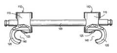
- FIG. 1shows a spinal implant system that includes a variable cross-link device or transverse connector according to an illustrative embodiment of the invention.
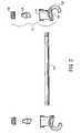
- FIG. 2illustrates an exploded view of variable cross-link devices according to an illustrative embodiment of the invention.
- FIG. 3depicts a perspective view of variable cross-link devices according to an exemplary embodiment of the invention.
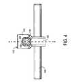
- FIG. 4shows a side view of a variable cross-link device according to an exemplary embodiment of the invention.
- FIG. 5illustrates an end view of variable cross-link devices according to an exemplary embodiment of the invention.
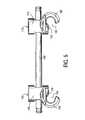
- FIG. 6depicts a transverse connection using variable cross-link devices according to an exemplary embodiment of the invention.
- FIG. 7shows another transverse connection using variable cross-link devices according to an exemplary embodiment of the invention.
- FIG. 8illustrates a cross-section of the variable cross-link device shown in FIG. 4 .
- the disclosed novel conceptsrelate to spinal implants with variable cross-link devices or transverse connectors.
- the cross-link devicesprovide poly-axial or variable motion, thus providing several degrees of freedom and facilitating conforming the implant to the patient's anatomy or desired formation or structure.
- the cross-link devicesallow supporting of the spine in fusion procedures. More specifically, the cross-link devices help to limit or eliminate undesired motion (e.g., torsional movement) in a fusion implant. In other applications, the variable cross-link devices help the surgeon to extend a fused portion of the spine to additional levels. In such cases, the surgeon may use extended longitudinal rods, and use cross-link devices to provide additional support and to link the new implants to the existing implants.
- the novel cross-link devicesprovide several advantages over conventional devices, as persons of ordinary skill in the art who have the benefit of the description of the invention appreciate.
- FIG. 1shows a spinal implant system that includes a variable cross-link device or transverse connector according to an illustrative embodiment of the invention.
- the implant systemmay include a pair of longitudinal rods or elongated members 103 .
- Longitudinal rods 103are affixed to spine 10 of the patient, disposed generally in a vertical direction along spine 10 .
- the surgeonmay use a variety of techniques to affix longitudinal rods 103 to spine 10 , as desired, and as persons of ordinary skill in the art who have the benefit of the description of the invention understand.
- the surgeonmay use coupling elements 106 , which may include fasteners such as screws, caps, set screws, hooks, etc.
- coupling elements 106may include pedicle screws, as persons of ordinary skill in the art who have the benefit of the description of the invention understand.
- the longitudinal rods 103immobilize and support one or more levels of spine 10 . More specifically, during a surgical procedure, the surgeon uses coupling elements 106 to affix longitudinal rods 103 to the vertebrae of spine 10 . Longitudinal rods 103 support and/or immobilize spine 10 and facilitate fusion in one or more levels, as desired, depending on the nature of the defect or injury in spine 10 . Persons of ordinary skill in the art who have the benefit of the description of the invention understand the details of the procedures, as well as the instruments and devices used to affix longitudinal rods 103 to spine 10 .
- the spinal implant systemalso includes a plurality of cross-link devices 112 (or poly-axial connectors), and one or more transverse rods or elongated members 109 .
- Each pair of cross-link devices 112couples to longitudinal rods 103 and also to a respective transverse rod 109 .
- variable cross-link devices 112the surgeon may also couple longitudinal rods 103 to each other at one or more locations, as desired. More specifically, at one or more desired locations, the surgeon may use a pair of variable cross-link devices 112 (or poly-axial connectors), together with transverse rod 109 , to further support and immobilize the spine.
- variable cross-links 112when used with transverse rod 109 , provide additional rigidity to the spinal implant.
- the additional rigidityhelps to reduce, limit, or eliminate undesired motions or stresses.
- the implanttends to limit or eliminate torsional movements in the affected levels of spine 10 , provides torsional stability to spine 10 , and therefore facilitates fusion in one or more desired levels.
- variable cross-link devicesoffer several advantages.
- the surgeonforms longitudinal rods 103 to conform them to the patient's anatomy, i.e., the physical properties and geometry of spine 10 .
- the surgeonalso forms longitudinal rods 103 in order to conform them to the cross-link device.
- variable cross-link devices 112provide the surgeon with more flexibility, and help achieve a better fit among the various parts of the implant. Viewed another way, by providing variable transverse cross-linking or coupling between longitudinal rods 103 , cross-link devices 112 more readily conform to the geometry and shape of longitudinal rods 103 and the anatomy of spine 10 .
- spinal implant systemsprovide better support and immobilization of spine 10 , thus accelerating the healing or fusion process.
- variable cross-link devicesuse a novel approach of transmitting force from a relatively small number of fasteners in order to couple to longitudinal rods 103 and transverse rod 109 .
- FIG. 2shows an exploded view of variable cross-link devices 112 according to an illustrative embodiment of the invention.
- the following descriptiondiscusses variable cross-link device 112 on the right side of the figure; a similar description applies to the cross-link device on the left side of the figure.
- Variable cross-link device 112includes body 115 , piston or rod engaging member 125 , and screw or closure top or cap or plug 130 .
- cross-link device 112may also include transverse rod 109 , as desired.
- the cross-link devicemay comprise either a connector (body 115 , rod engaging member 125 , and plug 130 ), or a combination of a connector with a transverse rod 109 (e.g., as an integral unit).
- onemay provide the variable cross-link as a combination of two variable cross-link devices 112 pre-assembled with a transverse rod 109 , as desired.
- Body 115has an opening or through hole (not shown explicitly) that allows an end of transverse rod 109 to pass through body 115 .
- the end of transverse rod 109may protrude from body 115 , as shown more clearly in FIG. 2 .
- the holemay have a diameter larger than the diameter of transverse rod 109 , as desired. That arrangement allows positioning transverse rod 109 in a number of positions with respect to body 115 of variable cross-link device 112 .
- the surgeonmay rotate body 115 with respect to transverse rod 109 in order to fit the implant to the patient's anatomy, or fit variable cross-link device 112 to the shape and structure of longitudinal rod(s) 103 and transverse rod 109 .
- body 115includes a curved or hook element or member 120 .
- Curved member 120outlines an opening or recess 140 . Opening 140 engages with longitudinal rod 103 (not shown explicitly), and helps couple body 115 to longitudinal rod 103 .
- Body 115may be made of a desired suitable material, such as titanium.
- Rod engaging member 125couples to transverse rod 109 , and couples body 115 to transverse rod 109 . As described below in detail, rod engaging member 125 also couples curved member 120 to longitudinal rod 103 (not shown explicitly).
- rod engaging member 125has a “U”-shaped portion or slot for engaging or coupling to one end of transverse rod 109 .
- the exemplary embodiment of rod engaging member 125 in FIG. 2also has a beveled portion or face, or conical face, that engages with, or couples to, longitudinal rod 103 (not shown explicitly).
- Rod engaging member 125may be made of a variety of suitable materials, for example, titanium.
- Plug 130screws or fastens in the top part of body 115 .
- Plug 130may have a variety of shapes, for example, it may have a hexagonal head.
- Plug 130may be made of a desired suitable material, such as titanium.
- rod engaging member 125When fastened in body 115 , plug 130 couples to transverse rod 109 , and exerts force onto it. Transverse rod 109 transmits or transfers this force to rod engaging member 125 . In response, rod engaging member 125 provides a compression coupling or fit to transverse rod 109 . Advantageously, rod engaging member 125 also provides a compression coupling or fit to longitudinal rod 103 (not shown explicitly).
- the implantmay include mechanisms to prevent or reduce the possibility of loosening or dislodging, either during surgery or thereafter, as desired.
- the end(s) of transverse rod 109may be widened to prevent it from uncoupling from device(s) 112 , by expanding the end(s) of rod 109 by applying force to it and deforming it (e.g., shaping or turning it to a ball or round shape).
- a “stake”may be added to plug 130 to prevent it from loosening or falling out.
- FIG. 3depicts a perspective view of a pair of variable cross-link devices according to an exemplary embodiment of the invention. More particularly, the illustration shows a pair of cross-link devices 112 coupled to a transverse rod 109 .
- body 115 of variable cross-link device 112includes an elongated, elliptical, or oblong hole.
- the topology of the holeallows rotation of body 115 with respect to transverse rod 109 , thus providing the surgeon with an additional degree of freedom.
- body 115includes curved member or hook 120 , shaped for coupling to longitudinal rod 103 (not shown explicitly).
- the inside surface of curved member 120may be shaped in order to couple to longitudinal rod 103 , and provide a compression or friction fit to it.
- the surgeonmay position each of variable cross-link devices 112 in a desired position along transverse rod 109 . More specifically, the surgeon may slide each of variable cross-link devices 112 along transverse rod 109 and fasten it in a position that accommodates the anatomy of spine 10 , the position and shape of longitudinal rods 103 , or both, as desired. In this manner, the inventive variable cross-link devices provide the surgeon with a degree of freedom in positioning and securing the implant within the patient's body.
- FIG. 4shows a side view of a variable cross-link device 112 according to an exemplary embodiment of the invention. More specifically, the figure shows how curved member 120 of body 115 of the variable cross-link device 112 couples to longitudinal rod 103 . Put another way, curved member 120 of body 115 “wraps” at least part-way around longitudinal rod 103 , and provides a compression or friction fit to it (in response to the force exerted by fastening plug 130 , as described below in detail).
- rod engaging member 125has a channeled or “U”-shaped slot that engages transverse rod 109 .
- the pressure exerted from fastening plug 130compresses or presses transverse rod 109 against rod engaging member 125 .
- the “U”-shaped slot of rod engaging member 125may match the physical characteristics of transverse rod 109 , and thus facilitate a compression or friction fit to it.
- the width of the opening in the “U”-shaped slot of rod engaging member 125may be close to, or the same as, the diameter of transverse rod 109 .
- This arrangementwould result in a relatively tight compression or friction fit between rod engaging member 125 and transverse rod 109 .
- the compression or friction fitprovides a relatively tight coupling of plug 130 , rod engaging member 125 , transverse rod 109 , and body 115 to one another.
- FIG. 5illustrates an end view of a pair of variable cross-link devices 112 according to an exemplary embodiment of the invention, coupled to a transverse rod 109 .
- curved member or hook 120allows “wrapping” around a longitudinal rod 103 (not shown explicitly), as described above. Put another way, curved member 120 receives or wraps around (at least partially) the lateral outside surface of the longitudinal rod 103 to which it couples.
- rod engaging member 125 in each variable cross-link device 112protrudes from body 115 .
- the protruding portion of rod engaging member 125helps to provide a compression or friction fit to longitudinal rod 103 .
- variable cross-link devices 112provide flexibility to the surgeon in shaping an implant system that suits the needs or anatomy of a particular patient.
- longitudinal rods 103may be parallel or non-parallel to each other, as desired.
- longitudinal rods 103may be skewed in orientation with respect to each other.
- longitudinal rods 103may be diverging or converging with respect to each other, as desired.
- FIG. 6depicts a transverse connection of longitudinal rods 103 , using variable cross-link devices 112 according to an exemplary embodiment of the invention.
- a pair of variable cross-link devices 112couple to each other a pair of vertically skewed longitudinal rods 103 .
- longitudinal rods 103do not occupy the same plane along spine 10 .
- variable cross-link devices 112Because of the flexibility that variable cross-link devices 112 provide, the surgeon may rotate or skew longitudinal rods 103 with respect to each other, as desired. Thus, the surgeon may rotate each variable cross-link device 112 with respect to transverse rod 109 , and thus accommodate a vertically skewed implant, as desired.
- FIG. 7shows another transverse connection of longitudinal rods 103 , using variable cross-link devices 112 according to an exemplary embodiment of the invention.
- a pair of variable cross-link devices 112couple to each other a pair of horizontally skewed longitudinal rods 103 .
- longitudinal rods 103may occupy the same horizontal plane (e.g., a plane along spine 10 ). They, however, may have a non-parallel configuration and diverge from each other or converge towards each other. As an example, the surgeon may wish to design converging longitudinal rods 103 in order to accommodate a progressively narrower spine.
- Variable cross-link devices 112provide the surgeon with additional flexibility by allowing the surgeon to skew longitudinal rods 103 with respect to each other, in either a converging or diverging configuration, as desired.
- the choice of the arrangementdepends on factors such as the patient's anatomy, the size and configuration of the components, etc., as persons of ordinary skill in the art who have the benefit of the description of the invention understand.
- variable cross-link devicesor poly-axial connectors
- the variations of movementmay occur in two axes (i.e., the x, and y axes), and movement about three axes (i.e., movement or rotation about each of the x, y, and z axes, 300 , 310 , 320 ) as shown in FIGS. 6 and 7 .
- the cross-linkprovides the capability for horizontal adjustment along the length of transverse rod 109 , vertical adjustment along longitudinal rods 103 , and anterior/posterior adjustment on longitudinal rods 103 .
- the variable cross-link devicesallow locking transverse rod 109 and longitudinal rods 103 without limiting their freedoms of movement (or variations of movement).
- Variable cross-link devicesprovide the additional advantage that, by fastening plug 130 , the surgeon can couple a variable cross-link device 112 to both longitudinal rod 103 and transverse rod 109 . (Note that, to lock the variable cross-link device at the other end of transverse rod 109 , the surgeon may use a similar procedure.) Locking variable cross-link device 112 to longitudinal rod(s) 103 and transverse rod 109 prevents or limits further movement or articulation of the implant.
- the surgeonfastens plug 130 for each variable cross-link device 112 . This feature simplifies the operation, reduces the number of steps that the surgeon takes, and may reduce the number of physical components.
- FIG. 8illustrates a cross-section of variable cross-link device 112 shown in FIG. 4 . More specifically, FIG. 8 shows a cross-section along the line marked A-A in FIG. 4 of variable cross-link device 112 . The cross-section shown in FIG. 8 illustrates the details of how the surgeon may affix variable cross-link device 112 by fastening plug 130 .
- Fastening plug 130exerts a force (labeled “F 1 ” in FIG. 8 ) to transverse rod 109 , and provides a compression fit between body 115 , plug 130 , and rod engaging member 125 of variable cross-link device 112 and transverse rod 109 .
- Fastening plug 130also pushes transverse rod 109 against rod engaging member 125 .
- plug 130causes rod engaging member 125 to extend downward into body 115 of variable cross-link device 112 .
- rod engaging member 125 in body 115causes the beveled portion of rod engaging member 125 to contact longitudinal rod 103 , and exert a force (labeled “F 2 ” in FIG. 8 ) against it.
- the application of this forcehelps to provide a compression or friction fit between rod engaging member 125 and longitudinal rod 103 .
- the application of force against longitudinal rod 103causes it to exert a force (labeled “F 3 ”) against curved member 120 of body 115 of variable cross-link device 112 .
- the exertion of force against curved member 120further causes a compression or friction fit between it and longitudinal rod 103 .
- variable cross-link device 112can simultaneously cause a compression or friction fit between variable cross-link device 112 and both transverse rod 109 and longitudinal rod 103 . Accordingly, unlike conventional devices, the surgeon need not fasten separate or individual fasteners.
- the slot in body 115 for accommodating transverse rod 109may be parallel to longitudinal rod 103 (or a desired angle with respect to rod 103 ), rather than being normal (or substantially or nearly normal) to longitudinal rod 103 .
- Such a configurationallows coupling two rods 103 , or two sections or pieces of rods 103 , to be coupled together, including the advantages of the connectors according to the invention, as described herein.
- the implants according to the inventionmay be used in minimally invasive surgery (MIS) procedures or in non-MIS procedures, as desired, and as persons of ordinary skill in the art who have the benefit of the description of the invention understand.
- MIS proceduresseek to reduce cutting, bleeding, and tissue damage or disturbance associated with implanting a spinal implant in a patient's body.
- Exemplary proceduresmay use a percutaneous technique for implanting longitudinal rods and coupling elements. Examples of MIS procedures and related apparatus are provided in U.S. patent application Ser. No. 10/698,049, filed Oct. 30, 2003, U.S. patent application Ser. No. 10/698,010, Oct. 30, 2003, and U.S. patent application Ser. No. 10/697,793, filed Oct. 30, 2003, incorporated herein by reference.
- variable cross-link devicesor poly-axial connectors
- plug 130used to lock the rods
- the surgeonmay percutaneously position and place the implant using the same technique and through the same wound exposure as with other spinal implants, then tighten or fasten plug 130 by inserting. Because plug 130 is accessible through the wound, one may couple the rods together by tightening plug 130 , as described above in detail, without using additional incisions or wounds.
- variable cross-link devicesor poly-axial connectors
- implanting the variable cross-link devicesdoes not entail additional exposures or cuts, as all insertion and locking of the poly-axial connector may be performed through the two existing exposure sites used to implant the longitudinal rods.
- Other details of the procedurewill be apparent to persons of ordinary skill in the art who have the benefit of the description of the invention.
Landscapes
- Health & Medical Sciences (AREA)
- Orthopedic Medicine & Surgery (AREA)
- Life Sciences & Earth Sciences (AREA)
- Neurology (AREA)
- Surgery (AREA)
- Heart & Thoracic Surgery (AREA)
- Engineering & Computer Science (AREA)
- Biomedical Technology (AREA)
- Nuclear Medicine, Radiotherapy & Molecular Imaging (AREA)
- Medical Informatics (AREA)
- Molecular Biology (AREA)
- Animal Behavior & Ethology (AREA)
- General Health & Medical Sciences (AREA)
- Public Health (AREA)
- Veterinary Medicine (AREA)
- Prostheses (AREA)
- Surgical Instruments (AREA)
Abstract
Description
Claims (10)
Priority Applications (3)
| Application Number | Priority Date | Filing Date | Title |
|---|---|---|---|
| US11/234,706US8226689B2 (en) | 2005-09-23 | 2005-09-23 | Apparatus and methods for spinal implant with variable link mechanism |
| EP06814918AEP1937169A1 (en) | 2005-09-23 | 2006-09-19 | Spinal implant with variable link mechanism |
| PCT/US2006/036429WO2007038076A1 (en) | 2005-09-23 | 2006-09-19 | Spinal implant with variable link mechanism |
Applications Claiming Priority (1)
| Application Number | Priority Date | Filing Date | Title |
|---|---|---|---|
| US11/234,706US8226689B2 (en) | 2005-09-23 | 2005-09-23 | Apparatus and methods for spinal implant with variable link mechanism |
Publications (2)
| Publication Number | Publication Date |
|---|---|
| US20070083201A1 US20070083201A1 (en) | 2007-04-12 |
| US8226689B2true US8226689B2 (en) | 2012-07-24 |
Family
ID=37492039
Family Applications (1)
| Application Number | Title | Priority Date | Filing Date |
|---|---|---|---|
| US11/234,706Expired - Fee RelatedUS8226689B2 (en) | 2005-09-23 | 2005-09-23 | Apparatus and methods for spinal implant with variable link mechanism |
Country Status (3)
| Country | Link |
|---|---|
| US (1) | US8226689B2 (en) |
| EP (1) | EP1937169A1 (en) |
| WO (1) | WO2007038076A1 (en) |
Cited By (9)
| Publication number | Priority date | Publication date | Assignee | Title |
|---|---|---|---|---|
| US20090030462A1 (en)* | 2007-07-26 | 2009-01-29 | Glenn R. Buttermann, M.D. | Segmental Orthopaedic device for spinal elongation and for treatment of Scoliosis |
| US20130325070A1 (en)* | 2012-06-01 | 2013-12-05 | Zimmer Spine | Device for fixing a bony structure to a support member |
| US8940020B2 (en) | 2012-04-06 | 2015-01-27 | DePuy Synthes Products, LLC | Rod connector |
| US20150150603A1 (en)* | 2005-03-02 | 2015-06-04 | Gmedelaware 2 Llc | Arthoplasty revision system and method |
| US9204908B2 (en)* | 2007-07-26 | 2015-12-08 | Dynamic Spine, Llc | Segmental orthopedic device for spinal elongation and for treatment of scoliosis |
| US9277950B2 (en) | 2010-06-10 | 2016-03-08 | Dynamic Spine, Llc | Low-profile, uniplanar bone screw |
| US9510870B2 (en) | 2007-09-25 | 2016-12-06 | DePuy Synthes Products, Inc. | Transconnector |
| US10575876B2 (en) | 2016-04-20 | 2020-03-03 | K2M, Inc. | Spinal stabilization assemblies with bone hooks |
| US20200146728A1 (en)* | 2018-11-14 | 2020-05-14 | Quandary Medical, Llc | Cross connection system for strengthening a stabilization construct |
Families Citing this family (43)
| Publication number | Priority date | Publication date | Assignee | Title |
|---|---|---|---|---|
| FR2812186B1 (en)* | 2000-07-25 | 2003-02-28 | Spine Next Sa | FLEXIBLE CONNECTION PIECE FOR SPINAL STABILIZATION |
| FR2812185B1 (en) | 2000-07-25 | 2003-02-28 | Spine Next Sa | SEMI-RIGID CONNECTION PIECE FOR RACHIS STABILIZATION |
| FR2831048B1 (en) | 2001-10-18 | 2004-09-17 | Ldr Medical | PROGRESSIVE APPROACH OSTEOSYNTHESIS DEVICE AND PRE-ASSEMBLY PROCESS |
| FR2831049B1 (en) | 2001-10-18 | 2004-08-13 | Ldr Medical | PLATE FOR OSTEOSYNTHESIS DEVICE AND PRE-ASSEMBLY METHOD |
| CN1304618C (en)* | 2002-04-05 | 2007-03-14 | 新日本制铁株式会社 | Pealite based rail excellent in wear resistance and ductility and method for production thereof |
| US9539012B2 (en) | 2002-10-30 | 2017-01-10 | Zimmer Spine, Inc. | Spinal stabilization systems with quick-connect sleeve assemblies for use in surgical procedures |
| AU2003287273C1 (en) | 2002-10-30 | 2010-01-07 | Zimmer Spine, Inc. | Spinal stabilization system insertion and methods |
| FR2870718B1 (en)* | 2004-05-25 | 2006-09-22 | Spine Next Sa | TREATMENT ASSEMBLY FOR THE DEGENERATION OF AN INTERVERTEBRAL DISC |
| US7621942B2 (en)* | 2005-03-21 | 2009-11-24 | Zimmer Spine, Inc. | Variable geometry occipital fixation plate |
| US8496686B2 (en)* | 2005-03-22 | 2013-07-30 | Gmedelaware 2 Llc | Minimally invasive spine restoration systems, devices, methods and kits |
| US20070299441A1 (en)* | 2006-06-09 | 2007-12-27 | Zachary M. Hoffman | Adjustable Occipital Plate |
| US7901433B2 (en) | 2006-10-04 | 2011-03-08 | Zimmer Spine, Inc. | Occipito-cervical stabilization system and method |
| US8147527B2 (en)* | 2006-11-28 | 2012-04-03 | Zimmer Spine, Inc. | Adjustable occipital plate |
| US8636737B2 (en)* | 2006-12-27 | 2014-01-28 | Zimmer Spine, Inc. | Modular occipital plate |
| US8246662B2 (en)* | 2006-12-27 | 2012-08-21 | Zimmer Spine, Inc. | Modular occipital plate |
| FR2916956B1 (en) | 2007-06-08 | 2012-12-14 | Ldr Medical | INTERSOMATIC CAGE, INTERVERTEBRAL PROSTHESIS, ANCHORING DEVICE AND IMPLANTATION INSTRUMENTATION |
| FR2918555B1 (en) | 2007-07-12 | 2010-04-02 | Ldr Medical | DEVICE AND SYSTEM FOR TRANSVERSE SPINACH CONNECTION |
| US8048129B2 (en) | 2007-08-15 | 2011-11-01 | Zimmer Spine, Inc. | MIS crosslink apparatus and methods for spinal implant |
| US9060813B1 (en) | 2008-02-29 | 2015-06-23 | Nuvasive, Inc. | Surgical fixation system and related methods |
| US8025678B2 (en)* | 2008-03-26 | 2011-09-27 | Depuy Spine, Inc. | Interspinous process spacer having tight access offset hooks |
| US8313512B2 (en)* | 2008-03-26 | 2012-11-20 | Depuy Spine, Inc. | S-shaped interspinous process spacer having tight access offset hooks |
| US8167908B2 (en)* | 2008-08-29 | 2012-05-01 | Zimmer Spine, Inc. | Polyaxial transverse connector |
| WO2010065795A1 (en) | 2008-12-03 | 2010-06-10 | Eminent Spine Llc | Spinal Cross-Connector and Method for Use of Same |
| EP2421454A4 (en)* | 2009-04-23 | 2013-12-11 | Spinal Elements Inc | Transverse connectors |
| US8246657B1 (en) | 2009-06-29 | 2012-08-21 | Nuvasive, Inc. | Spinal cross connector |
| US8657856B2 (en) | 2009-08-28 | 2014-02-25 | Pioneer Surgical Technology, Inc. | Size transition spinal rod |
| US9211144B2 (en)* | 2009-09-09 | 2015-12-15 | Globus Medical, Inc. | Spine surgery device and method |
| US9381044B2 (en) | 2010-01-26 | 2016-07-05 | Pioneer Surgical Technology, Inc. | Posterior spinal stabilization plate device |
| US9198696B1 (en) | 2010-05-27 | 2015-12-01 | Nuvasive, Inc. | Cross-connector and related methods |
| US9247964B1 (en) | 2011-03-01 | 2016-02-02 | Nuasive, Inc. | Spinal Cross-connector |
| US9387013B1 (en) | 2011-03-01 | 2016-07-12 | Nuvasive, Inc. | Posterior cervical fixation system |
| US9131963B2 (en)* | 2011-03-08 | 2015-09-15 | Life Spine, Inc. | Posterior cross connector assembly |
| US8740950B2 (en)* | 2011-12-08 | 2014-06-03 | Spine Wave, Inc. | Methods for percutaneously attaching a cross connector to contralateral spinal constructs |
| US9125691B2 (en) | 2011-12-23 | 2015-09-08 | Amendia, Inc. | Transverse crosslink device |
| US20140277163A1 (en)* | 2013-03-15 | 2014-09-18 | Ryan Kretzer | Reinforcement systems for spine stabilization constructs |
| US9707015B2 (en)* | 2014-01-14 | 2017-07-18 | Life Spine, Inc. | Implant for immobilizing cervical vertebrae |
| US20170265904A1 (en)* | 2016-03-16 | 2017-09-21 | Globus Medical, Inc. | Transverse connectors for spinal systems |
| WO2020035958A1 (en)* | 2018-08-16 | 2020-02-20 | Medtronic Sofamor Danek, Co., Ltd. | Spinal implant system and method |
| US11224466B2 (en) | 2019-05-13 | 2022-01-18 | Devin Datta | Devices and methods for treating spinal stress fractures |
| US20230346433A1 (en)* | 2020-05-04 | 2023-11-02 | K2M, Inc. | Segmental Correction And Spondylolisthesis Reduction |
| US11331125B1 (en) | 2021-10-07 | 2022-05-17 | Ortho Inventions, Llc | Low profile rod-to-rod coupler |
| CN114732505B (en)* | 2022-04-11 | 2025-08-29 | 中国人民解放军海军军医大学第二附属医院 | Double-rod compression reduction device for kyphosis |
| US20240299065A1 (en)* | 2023-03-08 | 2024-09-12 | Nuvasive, Inc. | Percutaneous posterior fixation |
Citations (26)
| Publication number | Priority date | Publication date | Assignee | Title |
|---|---|---|---|---|
| US5312402A (en)* | 1991-04-16 | 1994-05-17 | Synthes (U.S.A.) | Connection device |
| US5312405A (en) | 1992-07-06 | 1994-05-17 | Zimmer, Inc. | Spinal rod coupler |
| US5474551A (en)* | 1994-11-18 | 1995-12-12 | Smith & Nephew Richards, Inc. | Universal coupler for spinal fixation |
| US5487742A (en)* | 1990-03-08 | 1996-01-30 | Sofamore Danek Group | Transverse fixation device for a spinal osteosynthesis system |
| US5522816A (en)* | 1994-03-09 | 1996-06-04 | Acromed Corporation | Transverse connection for spinal column corrective devices |
| US5534002A (en)* | 1993-01-04 | 1996-07-09 | Danek Medical, Inc. | Spinal fixation system |
| FR2732887A1 (en) | 1995-04-12 | 1996-10-18 | Euros Sa | Connector for lengthwise and transverse spinal support rods |
| US5569246A (en) | 1993-12-28 | 1996-10-29 | Asahi Kogaku Kogyo Kabushiki Kaisha | Fixing instrument for spinal fusion members |
| US5624442A (en) | 1990-04-26 | 1997-04-29 | Cross Medical Products, Inc. | Transverse link for use with a spinal implant system |
| US5702393A (en)* | 1995-12-07 | 1997-12-30 | Groupe Lepine | Assembly device for elongate components of osteosynthesis, especially spinal, equipment |
| US5743911A (en)* | 1994-03-18 | 1998-04-28 | Sofamor S.N.C. | Fixing device for a rigid transverse connection device between rods of a spinal osteosynthesis system |
| US5947966A (en) | 1995-06-06 | 1999-09-07 | Sdgi Holdings, Inc. | Device for linking adjacent rods in spinal instrumentation |
| US5980523A (en) | 1998-01-08 | 1999-11-09 | Jackson; Roger | Transverse connectors for spinal rods |
| FR2795622A1 (en) | 1999-07-01 | 2001-01-05 | Gerard Vanacker | CONNECTOR FOR OSTEOSYNTHESIS SYSTEM FOR PROVIDING RIGID BOND BETWEEN TWO RODS OF SPINAL OSTEOSYNTHESIS SYSTEM, OSTEOSYNTHESIS SYSTEM USING SUCH CONNECTOR |
| WO2002015766A2 (en) | 2000-08-18 | 2002-02-28 | Blackstone Medical, Inc. | A surgical cross-connecting apparatus |
| US6352537B1 (en)* | 1998-09-17 | 2002-03-05 | Electro-Biology, Inc. | Method and apparatus for spinal fixation |
| US6368320B1 (en)* | 1997-12-09 | 2002-04-09 | (Dimso) Distribution Medicale Du Sud-Ouest | Connector for backbone osteosynthesis device |
| US20030023243A1 (en) | 2001-07-27 | 2003-01-30 | Biedermann Motech Gmbh | Bone screw and fastening tool for same |
| US20030045874A1 (en)* | 2001-08-31 | 2003-03-06 | Thomas James C. | Transverse connector assembly for spine fixation system |
| US6554832B2 (en) | 2001-04-02 | 2003-04-29 | Endius Incorporated | Polyaxial transverse connector |
| US6616668B2 (en) | 2000-06-09 | 2003-09-09 | Cross Medical Products, Inc. | Adjustable transverse connector for use with a spinal implant system |
| US20040143265A1 (en) | 2002-10-30 | 2004-07-22 | Landry Michael E. | Spinal stabilization systems and methods using minimally invasive surgical procedures |
| US6887241B1 (en) | 2000-10-06 | 2005-05-03 | Spinal Concepts, Inc. | Adjustable transverse connector with cam activated engagers |
| US20050149019A1 (en)* | 2003-12-19 | 2005-07-07 | Sasing Jude L. | Transverse connector for rod-based spinal implants |
| US20070016189A1 (en)* | 2005-06-30 | 2007-01-18 | Depuy Spine Sarl | Orthopedic clamping hook assembly |
| US20070083199A1 (en)* | 2003-09-04 | 2007-04-12 | Abbott Spine | Spinal implant |
Family Cites Families (1)
| Publication number | Priority date | Publication date | Assignee | Title |
|---|---|---|---|---|
| FR2835734B1 (en)* | 2002-02-11 | 2004-10-29 | Scient X | CONNECTION SYSTEM BETWEEN A SPINAL ROD AND A CROSS BAR |
- 2005
- 2005-09-23USUS11/234,706patent/US8226689B2/ennot_activeExpired - Fee Related
- 2006
- 2006-09-19EPEP06814918Apatent/EP1937169A1/ennot_activeWithdrawn
- 2006-09-19WOPCT/US2006/036429patent/WO2007038076A1/enactiveApplication Filing
Patent Citations (30)
| Publication number | Priority date | Publication date | Assignee | Title |
|---|---|---|---|---|
| US5487742A (en)* | 1990-03-08 | 1996-01-30 | Sofamore Danek Group | Transverse fixation device for a spinal osteosynthesis system |
| US5651789A (en) | 1990-03-08 | 1997-07-29 | Sofamor Danek Group | Transverse fixation device for ensuring a rigid transverse connection between two rods of a spinal osteosynthesis system |
| US5624442A (en) | 1990-04-26 | 1997-04-29 | Cross Medical Products, Inc. | Transverse link for use with a spinal implant system |
| US5312402A (en)* | 1991-04-16 | 1994-05-17 | Synthes (U.S.A.) | Connection device |
| US5312405A (en) | 1992-07-06 | 1994-05-17 | Zimmer, Inc. | Spinal rod coupler |
| US5534002A (en)* | 1993-01-04 | 1996-07-09 | Danek Medical, Inc. | Spinal fixation system |
| US5569246A (en) | 1993-12-28 | 1996-10-29 | Asahi Kogaku Kogyo Kabushiki Kaisha | Fixing instrument for spinal fusion members |
| US5522816A (en)* | 1994-03-09 | 1996-06-04 | Acromed Corporation | Transverse connection for spinal column corrective devices |
| US5743911A (en)* | 1994-03-18 | 1998-04-28 | Sofamor S.N.C. | Fixing device for a rigid transverse connection device between rods of a spinal osteosynthesis system |
| US5474551A (en)* | 1994-11-18 | 1995-12-12 | Smith & Nephew Richards, Inc. | Universal coupler for spinal fixation |
| FR2732887A1 (en) | 1995-04-12 | 1996-10-18 | Euros Sa | Connector for lengthwise and transverse spinal support rods |
| US5947966A (en) | 1995-06-06 | 1999-09-07 | Sdgi Holdings, Inc. | Device for linking adjacent rods in spinal instrumentation |
| US5702393A (en)* | 1995-12-07 | 1997-12-30 | Groupe Lepine | Assembly device for elongate components of osteosynthesis, especially spinal, equipment |
| US6368320B1 (en)* | 1997-12-09 | 2002-04-09 | (Dimso) Distribution Medicale Du Sud-Ouest | Connector for backbone osteosynthesis device |
| US5980523A (en) | 1998-01-08 | 1999-11-09 | Jackson; Roger | Transverse connectors for spinal rods |
| US6352537B1 (en)* | 1998-09-17 | 2002-03-05 | Electro-Biology, Inc. | Method and apparatus for spinal fixation |
| FR2795622A1 (en) | 1999-07-01 | 2001-01-05 | Gerard Vanacker | CONNECTOR FOR OSTEOSYNTHESIS SYSTEM FOR PROVIDING RIGID BOND BETWEEN TWO RODS OF SPINAL OSTEOSYNTHESIS SYSTEM, OSTEOSYNTHESIS SYSTEM USING SUCH CONNECTOR |
| US6616668B2 (en) | 2000-06-09 | 2003-09-09 | Cross Medical Products, Inc. | Adjustable transverse connector for use with a spinal implant system |
| WO2002015766A2 (en) | 2000-08-18 | 2002-02-28 | Blackstone Medical, Inc. | A surgical cross-connecting apparatus |
| US6887241B1 (en) | 2000-10-06 | 2005-05-03 | Spinal Concepts, Inc. | Adjustable transverse connector with cam activated engagers |
| US6554832B2 (en) | 2001-04-02 | 2003-04-29 | Endius Incorporated | Polyaxial transverse connector |
| US20030023243A1 (en) | 2001-07-27 | 2003-01-30 | Biedermann Motech Gmbh | Bone screw and fastening tool for same |
| US20030045874A1 (en)* | 2001-08-31 | 2003-03-06 | Thomas James C. | Transverse connector assembly for spine fixation system |
| US20040172022A1 (en) | 2002-10-30 | 2004-09-02 | Landry Michael E. | Bone fastener assembly for a spinal stabilization system |
| US20040143265A1 (en) | 2002-10-30 | 2004-07-22 | Landry Michael E. | Spinal stabilization systems and methods using minimally invasive surgical procedures |
| US7250052B2 (en) | 2002-10-30 | 2007-07-31 | Abbott Spine Inc. | Spinal stabilization systems and methods |
| US20070083199A1 (en)* | 2003-09-04 | 2007-04-12 | Abbott Spine | Spinal implant |
| US7901436B2 (en)* | 2003-09-04 | 2011-03-08 | Zimmer Spine S.A.S. | Spinal implant |
| US20050149019A1 (en)* | 2003-12-19 | 2005-07-07 | Sasing Jude L. | Transverse connector for rod-based spinal implants |
| US20070016189A1 (en)* | 2005-06-30 | 2007-01-18 | Depuy Spine Sarl | Orthopedic clamping hook assembly |
Non-Patent Citations (2)
| Title |
|---|
| International Search Report and Written Opinion for PCT/US2006/ 036429 mailed Dec. 28, 2006, 14 pages. |
| Lenke, Lawrence G., "Segmental Spinal Stabilization Using a Low-Profile Crosslinking Device," retrieved Jan. 25, 2010 from http://www.spineuniverse,com/exams-tests/devices/segmental-spinal-stabilization-using-low-profile; posted Feb. 13, 2004, 3 pages. |
Cited By (17)
| Publication number | Priority date | Publication date | Assignee | Title |
|---|---|---|---|---|
| US20150150603A1 (en)* | 2005-03-02 | 2015-06-04 | Gmedelaware 2 Llc | Arthoplasty revision system and method |
| US9526530B2 (en)* | 2005-03-02 | 2016-12-27 | Globus Medical, Inc. | Arthoplasty revision system and method |
| US9204908B2 (en)* | 2007-07-26 | 2015-12-08 | Dynamic Spine, Llc | Segmental orthopedic device for spinal elongation and for treatment of scoliosis |
| US20090030462A1 (en)* | 2007-07-26 | 2009-01-29 | Glenn R. Buttermann, M.D. | Segmental Orthopaedic device for spinal elongation and for treatment of Scoliosis |
| US8790380B2 (en) | 2007-07-26 | 2014-07-29 | Dynamic Spine, Llc | Segmental orthopaedic device for spinal elongation and for treatment of scoliosis |
| US9204899B2 (en) | 2007-07-26 | 2015-12-08 | Dynamic Spine, Llc | Segmental orthopedic device for spinal elongation and for treatment of scoliosis |
| US9949768B2 (en) | 2007-09-25 | 2018-04-24 | DePuy Synthes Products, Inc. | Transconnector |
| US9510870B2 (en) | 2007-09-25 | 2016-12-06 | DePuy Synthes Products, Inc. | Transconnector |
| US9277950B2 (en) | 2010-06-10 | 2016-03-08 | Dynamic Spine, Llc | Low-profile, uniplanar bone screw |
| US8940020B2 (en) | 2012-04-06 | 2015-01-27 | DePuy Synthes Products, LLC | Rod connector |
| US8936625B2 (en)* | 2012-06-01 | 2015-01-20 | Zimmer Spine | Device for fixing a bony structure to a support member |
| US9427263B2 (en)* | 2012-06-01 | 2016-08-30 | Zimmer Spine | Device for fixing a bony structure to a support member |
| US20150094768A1 (en)* | 2012-06-01 | 2015-04-02 | Zimmer Spine | Device for fixing a bony structure to a support member |
| US20130325070A1 (en)* | 2012-06-01 | 2013-12-05 | Zimmer Spine | Device for fixing a bony structure to a support member |
| US10575876B2 (en) | 2016-04-20 | 2020-03-03 | K2M, Inc. | Spinal stabilization assemblies with bone hooks |
| US20200146728A1 (en)* | 2018-11-14 | 2020-05-14 | Quandary Medical, Llc | Cross connection system for strengthening a stabilization construct |
| US11653956B2 (en)* | 2018-11-14 | 2023-05-23 | Quandary Medical, Llc | Cross connection system for strengthening a stabilization construct |
Also Published As
| Publication number | Publication date |
|---|---|
| EP1937169A1 (en) | 2008-07-02 |
| US20070083201A1 (en) | 2007-04-12 |
| WO2007038076A1 (en) | 2007-04-05 |
Similar Documents
| Publication | Publication Date | Title |
|---|---|---|
| US8226689B2 (en) | Apparatus and methods for spinal implant with variable link mechanism | |
| US7967845B2 (en) | Head-to-head connector spinal fixation system | |
| US7901433B2 (en) | Occipito-cervical stabilization system and method | |
| US10010352B2 (en) | Adjustable rod assembly | |
| US7803174B2 (en) | Dorsal adjusting multi-rod connector | |
| US7867255B2 (en) | Spinal rod connector system and method for a bone anchor | |
| US9629663B2 (en) | Rod attachment for head to head cross connector | |
| US8915945B2 (en) | Adjustable multi-axial spinal coupling assemblies | |
| USRE39035E1 (en) | Universal coupler for spinal fixation | |
| USRE39325E1 (en) | Spinal fixation apparatus and method | |
| US8147519B2 (en) | Variable angle rod connectors and the methods of use | |
| US7857834B2 (en) | Spinal implant fixation assembly | |
| US7967848B2 (en) | Spring-loaded dynamic pedicle screw assembly | |
| US20090264926A1 (en) | Spinal Fixation System | |
| US20050192573A1 (en) | Biased angle polyaxial pedicle screw assembly | |
| EP4033994B1 (en) | Spinal fixation device with rotatable connector |
Legal Events
| Date | Code | Title | Description |
|---|---|---|---|
| AS | Assignment | Owner name:ABBOTT SPINE, INC., TEXAS Free format text:ASSIGNMENT OF ASSIGNORS INTEREST;ASSIGNORS:JONES, ROBERT J.;FORTON, CHARLES R.;SIGNING DATES FROM 20060103 TO 20060109;REEL/FRAME:017300/0479 Owner name:ABBOTT SPINE, INC., TEXAS Free format text:ASSIGNMENT OF ASSIGNORS INTEREST;ASSIGNORS:JONES, ROBERT J.;FORTON, CHARLES R.;REEL/FRAME:017300/0479;SIGNING DATES FROM 20060103 TO 20060109 | |
| AS | Assignment | Owner name:ZIMMER SPINE AUSTIN, INC., TEXAS Free format text:CHANGE OF NAME;ASSIGNOR:ABBOTT SPINE INC.;REEL/FRAME:023281/0468 Effective date:20081215 | |
| AS | Assignment | Owner name:ZIMMER SPINE, INC., MINNESOTA Free format text:MERGER;ASSIGNOR:ZIMMER SPINE AUSTIN, INC.;REEL/FRAME:023300/0875 Effective date:20090828 | |
| STCF | Information on status: patent grant | Free format text:PATENTED CASE | |
| CC | Certificate of correction | ||
| FPAY | Fee payment | Year of fee payment:4 | |
| MAFP | Maintenance fee payment | Free format text:PAYMENT OF MAINTENANCE FEE, 8TH YEAR, LARGE ENTITY (ORIGINAL EVENT CODE: M1552); ENTITY STATUS OF PATENT OWNER: LARGE ENTITY Year of fee payment:8 | |
| AS | Assignment | Owner name:ZIMMER BIOMET SPINE, INC., INDIANA Free format text:MERGER;ASSIGNOR:ZIMMER SPINE, INC.;REEL/FRAME:059232/0356 Effective date:20160930 | |
| AS | Assignment | Owner name:JPMORGAN CHASE BANK, N.A., AS ADMINISTRATIVE AGENT, NEW YORK Free format text:SECURITY INTEREST;ASSIGNORS:BIOMET 3I, LLC;EBI, LLC;ZIMMER BIOMET SPINE, INC.;AND OTHERS;REEL/FRAME:059293/0213 Effective date:20220228 | |
| FEPP | Fee payment procedure | Free format text:MAINTENANCE FEE REMINDER MAILED (ORIGINAL EVENT CODE: REM.); ENTITY STATUS OF PATENT OWNER: LARGE ENTITY | |
| AS | Assignment | Owner name:CERBERUS BUSINESS FINANCE AGENCY, LLC, NEW YORK Free format text:GRANT OF A SECURITY INTEREST -- PATENTS;ASSIGNORS:ZIMMER BIOMET SPINE, LLC;EBI, LLC;REEL/FRAME:066970/0806 Effective date:20240401 | |
| AS | Assignment | Owner name:ZIMMER BIOMET SPINE, LLC (F/K/A ZIMMER BIOMET SPINE, INC.), COLORADO Free format text:RELEASE BY SECURED PARTY;ASSIGNOR:JPMORGAN CHASE BANK, N.A.;REEL/FRAME:066973/0833 Effective date:20240401 Owner name:EBI, LLC, NEW JERSEY Free format text:RELEASE BY SECURED PARTY;ASSIGNOR:JPMORGAN CHASE BANK, N.A.;REEL/FRAME:066973/0833 Effective date:20240401 | |
| LAPS | Lapse for failure to pay maintenance fees | Free format text:PATENT EXPIRED FOR FAILURE TO PAY MAINTENANCE FEES (ORIGINAL EVENT CODE: EXP.); ENTITY STATUS OF PATENT OWNER: LARGE ENTITY | |
| STCH | Information on status: patent discontinuation | Free format text:PATENT EXPIRED DUE TO NONPAYMENT OF MAINTENANCE FEES UNDER 37 CFR 1.362 | |
| FP | Lapsed due to failure to pay maintenance fee | Effective date:20240724 | |
| AS | Assignment | Owner name:ZIMMER BIOMET SPINE, LLC, COLORADO Free format text:CHANGE OF NAME;ASSIGNOR:ZIMMER BIOMET SPINE, INC.;REEL/FRAME:069772/0121 Effective date:20240220 Owner name:HIGHRIDGE MEDICAL, LLC, COLORADO Free format text:CHANGE OF NAME;ASSIGNOR:ZIMMER BIOMET SPINE, LLC;REEL/FRAME:069772/0248 Effective date:20240405 |