US8226687B2 - Apparatus and method for dynamic vertebral stabilization - Google Patents
Apparatus and method for dynamic vertebral stabilizationDownload PDFInfo
- Publication number
- US8226687B2 US8226687B2US12/582,977US58297709AUS8226687B2US 8226687 B2US8226687 B2US 8226687B2US 58297709 AUS58297709 AUS 58297709AUS 8226687 B2US8226687 B2US 8226687B2
- Authority
- US
- United States
- Prior art keywords
- vertebra
- vertebrae
- resilient
- path
- stabilization system
- Prior art date
- Legal status (The legal status is an assumption and is not a legal conclusion. Google has not performed a legal analysis and makes no representation as to the accuracy of the status listed.)
- Expired - Fee Related
Links
Images


Classifications
- A—HUMAN NECESSITIES
- A61—MEDICAL OR VETERINARY SCIENCE; HYGIENE
- A61B—DIAGNOSIS; SURGERY; IDENTIFICATION
- A61B17/00—Surgical instruments, devices or methods
- A61B17/56—Surgical instruments or methods for treatment of bones or joints; Devices specially adapted therefor
- A61B17/58—Surgical instruments or methods for treatment of bones or joints; Devices specially adapted therefor for osteosynthesis, e.g. bone plates, screws or setting implements
- A61B17/68—Internal fixation devices, including fasteners and spinal fixators, even if a part thereof projects from the skin
- A61B17/70—Spinal positioners or stabilisers, e.g. stabilisers comprising fluid filler in an implant
- A61B17/7001—Screws or hooks combined with longitudinal elements which do not contact vertebrae
- A61B17/7002—Longitudinal elements, e.g. rods
- A61B17/7019—Longitudinal elements having flexible parts, or parts connected together, such that after implantation the elements can move relative to each other
- A61B17/7026—Longitudinal elements having flexible parts, or parts connected together, such that after implantation the elements can move relative to each other with a part that is flexible due to its form
- A61B17/7028—Longitudinal elements having flexible parts, or parts connected together, such that after implantation the elements can move relative to each other with a part that is flexible due to its form the flexible part being a coil spring
- A—HUMAN NECESSITIES
- A61—MEDICAL OR VETERINARY SCIENCE; HYGIENE
- A61B—DIAGNOSIS; SURGERY; IDENTIFICATION
- A61B17/00—Surgical instruments, devices or methods
- A61B17/56—Surgical instruments or methods for treatment of bones or joints; Devices specially adapted therefor
- A61B17/58—Surgical instruments or methods for treatment of bones or joints; Devices specially adapted therefor for osteosynthesis, e.g. bone plates, screws or setting implements
- A61B17/68—Internal fixation devices, including fasteners and spinal fixators, even if a part thereof projects from the skin
- A61B17/70—Spinal positioners or stabilisers, e.g. stabilisers comprising fluid filler in an implant
- A61B17/7001—Screws or hooks combined with longitudinal elements which do not contact vertebrae
- A61B17/7002—Longitudinal elements, e.g. rods
- A61B17/7004—Longitudinal elements, e.g. rods with a cross-section which varies along its length
- A61B17/7007—Parts of the longitudinal elements, e.g. their ends, being specially adapted to fit around the screw or hook heads
- A—HUMAN NECESSITIES
- A61—MEDICAL OR VETERINARY SCIENCE; HYGIENE
- A61B—DIAGNOSIS; SURGERY; IDENTIFICATION
- A61B17/00—Surgical instruments, devices or methods
- A61B17/56—Surgical instruments or methods for treatment of bones or joints; Devices specially adapted therefor
- A61B17/58—Surgical instruments or methods for treatment of bones or joints; Devices specially adapted therefor for osteosynthesis, e.g. bone plates, screws or setting implements
- A61B17/68—Internal fixation devices, including fasteners and spinal fixators, even if a part thereof projects from the skin
- A61B17/70—Spinal positioners or stabilisers, e.g. stabilisers comprising fluid filler in an implant
- A61B17/7001—Screws or hooks combined with longitudinal elements which do not contact vertebrae
- A61B17/7002—Longitudinal elements, e.g. rods
- A61B17/7019—Longitudinal elements having flexible parts, or parts connected together, such that after implantation the elements can move relative to each other
- A61B17/7025—Longitudinal elements having flexible parts, or parts connected together, such that after implantation the elements can move relative to each other with a sliding joint
- A—HUMAN NECESSITIES
- A61—MEDICAL OR VETERINARY SCIENCE; HYGIENE
- A61B—DIAGNOSIS; SURGERY; IDENTIFICATION
- A61B17/00—Surgical instruments, devices or methods
- A61B17/56—Surgical instruments or methods for treatment of bones or joints; Devices specially adapted therefor
- A61B17/58—Surgical instruments or methods for treatment of bones or joints; Devices specially adapted therefor for osteosynthesis, e.g. bone plates, screws or setting implements
- A61B17/68—Internal fixation devices, including fasteners and spinal fixators, even if a part thereof projects from the skin
- A61B17/70—Spinal positioners or stabilisers, e.g. stabilisers comprising fluid filler in an implant
- A61B17/7049—Connectors, not bearing on the vertebrae, for linking longitudinal elements together
- A61B17/7052—Connectors, not bearing on the vertebrae, for linking longitudinal elements together of variable angle or length
Definitions
- the present inventionrelates generally to orthopedic medicine, and more precisely, to systems and methods for restricting relative motion between vertebrae.
- Back painis not only uncomfortable, but can be particularly debilitating.
- Many people who wish to participate in sports, manual labor, or even sedentary employmentare unable to do so because of pains that arise from motion of or pressure on the spinal column.
- Such painsare often caused by traumatic, inflammatory, metabolic, synovial, neoplastic and degenerative disorders of the spine.
- intervertebral discsthat separate adjacent vertebrae from each other serve to provide stiffness that helps to restrain relative motion of the vertebrae in flexion, extension, axial rotation, and lateral bending.
- a damaged discmay provide inadequate stiffness along one or more modes of spinal motion. Inadequate stiffness may result in excessive relative vertebral motion when the spine is under a given load, as when the patient uses the muscles of the back. Such excessive relative motion may cause further damage to the disc, thereby causing back pain and ultimately, requiring replacement of the disc and/or other operations to decompress nerves affected by central, lateral or foraminal stenosis.
- Some stabilization deviceshave been proposed to restrict, but not entirely prevent, relative motion between adjacent vertebrae. Such devices are often somewhat complex and/or bulky. Many such devices cannot be tailored to limit the types of motion (i.e., flexion/extension, axial rotation, or lateral bending) that are most painful. Additionally, in the event that stabilization ultimately becomes insufficient, most known stabilization devices do not provide any mechanism that can be used to more fully secure the spinal motion segment.
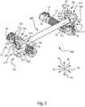
- FIG. 1is a perspective view of the L4 and L5 vertebrae of a spinal column, with left and right apparatus according to one embodiment of the invention attached to stabilize relative motion of the vertebrae.
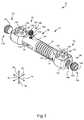
- FIG. 2is an exploded, perspective view of the apparatus of FIG. 1 .
- FIG. 3is a partially exploded, perspective view illustrating the apparatus of FIG. 1 with optional components including end caps and a set screw.
- FIG. 4is a perspective view of the apparatus of FIG. 1 , with the end caps and set screw in place.
- FIG. 5is a perspective view of the left and right apparatus of FIG. 1 , with a crosslink used to limit relative rotation of the left and right apparatus.
- FIG. 6is a chart illustrating corrected and pathological rotation/moment curves for typical prior art stabilization devices.
- FIG. 7is a chart illustrating natural (corrected) and pathological rotation/moment curves for the apparatus of FIG. 1 .
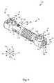
- FIG. 8is an exploded, perspective view illustrating an apparatus according to one alternative embodiment of the invention.
- FIG. 9is a perspective, partially cutaway view of the apparatus of FIG. 8 .
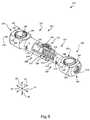
- FIG. 10is a perspective view of the apparatus of FIG. 8 , with end caps and a set screw in place.
- the present inventionadvances the state of the art by providing systems and methods that can be used to stabilize relative motion between two vertebrae.
- the present inventioncan be used as an alternative to spinal fusion to alleviate back pain resulting from traumatic, inflammatory, metabolic, synovial, neoplastic and degenerative spinal disorders.
- the configuration and operation of at least one embodiment of the inventionwill be shown and described in greater detail with reference to FIGS. 1 and 2 , as follows.
- telescopic engagementand variations thereof refer to two members, wherein a portion of one hollow member fits around a portion of a second member to permit relative linear motion of the two members.
- Locking of two membersrefers to substantially preventing relative translation or rotation between the members along at least one axis.
- Generally symmetricalrefers to items that are arranged in a manner that is symmetrical or nearly symmetrical to each other, with no requirement of precise symmetry. For example, the left and right sides of the spinal column may be considered to be generally symmetrical, despite the fact that anatomical differences and asymmetries will exist between them.
- Two components that are “integrally formed” with each otherare formed as a single piece.
- FIG. 1a perspective view illustrates a portion of a spine 10 .
- FIG. 1illustrates only the bony structures; accordingly, ligaments, cartilage, and other soft tissues are omitted for clarity.
- the spine 10has a cephalad direction 12 , a caudal direction 14 , an anterior direction 16 , a posterior direction 18 , and a medial/lateral axis 20 , all of which are oriented as shown by the arrows bearing the same reference numerals.
- “left” and “right”are used with reference to a posterior view, i.e., a view from behind the spine 10 .
- Medialrefers to a position or orientation toward a sagittal plane (i.e., plane of symmetry that separates left and right sides from each other) of the spine 10
- lateralrefers to a position or orientation relatively further from the sagittal plane.
- the portion of the spine 10 illustrated in FIG. 1includes a first vertebra 24 , which may be the L5 (Fifth Lumbar) vertebra of a patient, and a second vertebra 26 , which may be the L4 (Fourth Lumbar) vertebra of the patient.
- the systems and methodsmay be applicable to any vertebra or vertebrae of the spine 10 and/or the sacrum (not shown).
- the term “vertebra”may be broadly interpreted to include the sacrum.
- the first vertebra 24has a body 28 with a generally disc-like shape and two pedicles 30 that extend posteriorly from the body 28 .
- a posterior arch, or lamina 32extends between the posterior ends of the pedicles 30 to couple the pedicles 30 together.
- the first vertebra 24also has a pair of transverse processes 34 that extend laterally from the pedicles 30 generally along the medial/lateral axis 20 , and a spinous process 36 that extends from the lamina 32 along the posterior direction 18 .
- the first vertebra 24also has a pair of superior facets 38 , which are positioned toward the top of the first vertebra 24 and face generally medially. Additionally, the first vertebra 24 has inferior facets 40 , which are positioned toward the bottom of the first vertebra 24 and face generally laterally. Each of the pedicles 30 of the first vertebra 24 has a saddle point 42 , which is positioned generally at the center of the juncture of each superior facet 38 with the adjacent transverse process 34 .
- the second vertebra 26has a body 48 from which two pedicles 50 extend posteriorly.
- a posterior arch, or lamina 52extends between the posterior ends of the pedicles 50 to couple the pedicles 50 together.
- the second vertebra 26also has a pair of transverse processes 54 , each of which extends from the corresponding pedicle 50 generally along the medial/lateral axis 20 , and a spinous process 56 that extends from the lamina 52 along the posterior direction 18 .
- the second vertebra 26also has a pair of superior facets 58 , which are positioned toward the top of the second vertebra 26 and face generally inward. Additionally, the second vertebra 26 has inferior facets 60 , which are positioned toward the bottom of the second vertebra 26 and face generally outward. Each of the pedicles 60 of the second vertebra 26 has a saddle point 62 , which is positioned generally at the center of the juncture of each superior facet 58 with the adjacent transverse process 54 .
- the superior facets 38 of the first vertebra 24articulate (i.e., slide and/or press) with the inferior facets 60 of the second vertebra 26 to limit relative motion between the first and second vertebrae 24 , 26 .
- the combination of each superior facet 38 with the adjacent inferior facet 60provides a facet joint 64 .
- the first and second vertebrae 24 , 26thus define two facet joints 64 that span the distance between the first and second vertebrae 24 , 26 .
- the inferior facets 40 of the first vertebra 40 and the superior facets 58 of the second vertebra 26are part of other facet joints that control motion between the first and second vertebrae 24 , 26 and adjacent vertebrae (not shown) and/or the sacrum (also not shown).
- the vertebrae 24 , 26are separated from each other by an intervertebral disc 66 .
- an apparatus 70is coupled to the vertebrae 24 , 26 on either side of the sagittal plane to provide dynamic stabilization.
- dynamic stabilizationrefers to selectively limiting, but not entirely preventing, the relative motion of two objects.
- the apparatus 70may be termed a “stabilizer.”
- the apparatus 70is designed to preserve relatively free relative motion between the saddle points 42 , 62 of the vertebrae 24 , 26 along the cephalad and caudal directions 12 , 14 , thereby permitting flexion, extension, and lateral bending of the spine 10 with little restriction.
- the apparatus 70is also designed to significantly restrict relative motion between the saddle points 42 , 62 along the anterior direction 16 , the posterior direction 18 , and the medial/lateral axis 20 . Accordingly, rotation of the spine 10 and relative anterior/posterior or medial/lateral motion of the vertebrae 24 , 26 under shear are restricted.
- each apparatus 70has a bridge 72 , a stabilization rod 74 (not visible in FIG. 1 ), a pair of pins 76 , a pair of castle nuts 78 , and a pair of fixation members 80 .
- the fixation members 70are implanted in the pedicles 30 , 50 of the vertebrae 24 , 26 , respectively. More precisely, each of the fixation members 70 has a distal end (not shown) implanted in the pedicle 30 or 50 and a proximal end 84 that is exposed to protrude from the corresponding saddle point 42 or 62 .
- Each proximal end 84has threads 86 that enable threaded attachment of the corresponding castle nut 78 .
- the remainder of the apparatus 70is secured to the saddle points 42 , 62 via the castle nuts 78 .
- the bridge 72spans the distance between the saddle points 42 , 62 in a manner that enables relative cephalad/caudal motion with resilient support.
- the stabilization rod 74is movably secured within the bridge 72 via the pins 76 to limit relative motion between the saddle points 42 , 62 along the anterior direction 16 , the posterior direction 18 , and the medial/lateral axis 20 .
- FIG. 2an exploded, perspective view illustrates one of the apparatus 70 of FIG. 1 in isolation.
- the bridge 72has a first end 92 , a second end 94 , and a central portion 96 between the first and second ends 92 , 94 .
- the first end 92may be coupled to the first vertebra 24
- the second end 94may be coupled to the second vertebra 26 , so that upon implantation, the first end 92 is generally cephalad and the second end 94 is generally caudal.
- Each of the first and second ends 92 , 94has a mounting interface 100 that facilitates attachment of the first or second end 92 or 94 to the corresponding saddle point 42 or 62 .
- Each of the first and second ends 92 , 94also has a mounting aperture 102 from which the corresponding mounting interface 100 extends.
- the mounting interfaces 100 and the mounting apertures 102may each be sized to permit passage of the corresponding proximal end 84 therethrough.
- the mounting interfaces 100 and mounting apertures 102are sufficiently large that the proximal end 84 may pass therethrough at a variety of angles nonparallel to the axis of the mounting interface 100 and mounting aperture 102 .
- the apparatus 70accommodates spinal morphologies in which the pedicles 30 , 50 are not perpendicular to the desired orientation of the bridge 72 by permitting the fixation members 80 to extend non-perpendicular to the bridge 72 .
- Each mounting interface 100has a generally concave, semispherical shape that is designed to receive and compress the corresponding castle nut 78 to substantially prevent relative rotation between the bridge 72 and the corresponding fixation member 80 . Therefore, the orientation of the bridge 72 with respect to the fixation members 80 may be fixed in any of a variety of orientations to accommodate differing spinal morphologies. The manner in which the castle nuts 78 cooperate with the mounting interfaces 100 will be described in greater detail subsequently.
- each of the mounting interfaces 100has an interior orifice 106 and an exterior orifice 108 .
- the interior orifices 106provide communication with a bore 112 of the central portion 96 of the bridge 112 , and the exterior orifices 108 provide access to the interior orifices 106 .
- the stabilization rod 74may easily be installed in the bore 112 by inserting the stabilization rod 74 through one of the exterior orifices 108 , and then through the adjacent interior orifice 106 .
- the central portion 96has a pin registration slot 114 adjacent to the first end 92 , and a pin registration orifice 116 adjacent to the second end 94 .
- the pin registration slot 114 and the pin registration orifice 116communicate with the bore 112 , and are designed to receive the pins 76 . More precisely, the pin registration orifice 116 receives the corresponding pin 76 such that the pin 76 is unable to move with respect to the bridge 72 along the cephalad, caudal, anterior, and posterior directions 12 , 14 , 16 , 18 .
- the pin registration slot 118receives the other pin 76 such that the pin 76 is unable to move with respect to the bridge 72 along the anterior and posterior directions 16 , 18 , but may move along the pin registration slot 118 in the cephalad and caudal directions 12 , 14 .
- the central portion 96has a supplemental orifice 118 , which may be used to carry out various functions.
- a set screw(not shown in FIG. 1 ) or other implement may be seated in the supplemental orifice 118 to restrict sliding of the stabilization rod 74 within the bore 112 , thereby converting the apparatus 70 from a stabilization device to a fixation, or fusion device.
- the central portion 96also has a resilient section 120 , which may take the form of a linear spring integrally formed with the remainder of the bridge 72 .
- the resilient section 120permits the first and second ends 92 , 94 to move toward or away from each other to enable relative cephalad/caudal motion of the saddle points 42 , 62 of the vertebrae 24 , 26 , respectively.
- the resilient section 120also provides resilient force tending to push or pull the ends 92 , 94 into a relative position in which the resilient section 120 is substantially undeflected. Such a position may correspond to a spinal disposition in which the vertebrae 24 , 26 are neither flexed nor extended with respect to each other.
- the resilient section 120is integrally formed with the first and second ends 92 , 94 of the bridge 72 .
- a resilient sectionmay be separately formed from ends to which the resilient section is permanently or removably attached. For example, if the resilient section 120 were a separate piece from the ends 92 , 94 , the stabilization rod 74 would act to hold the resilient section 120 and the ends 92 , 94 together after the bridge 72 and the stabilization rod 74 had been assembled.
- the stabilization rod 74has a first end 124 , a second end 126 , and a central portion 128 between the first and second ends 124 , 126 .
- Each of the first and second ends 124 , 126has a pin registration orifice 132 sized to receive the corresponding pin 76 . More specifically, the pin registration orifices 132 may be sized to receive the pins 76 with some interference to provide a press fit so that, once inserted into the orifices 132 , the pins 76 remain in place until deliberately removed.
- the ends 124 , 126may each be sized to fit into the bore 112 of the bridge 72 with relatively little clearance to maintain coaxiality between the bridge 72 and the stabilization rod 74 .
- coaxialitymay be maintained by providing relatively small clearance between the pins 76 and the pin registration slot 114 and the pin registration orifice 116 . Maintaining coaxiality between the bridge 72 and the stabilization rod 74 restricts relative motion of the first and second ends 92 , 94 of the bridge 72 to motion along the axis of the bridge 72 , thereby permitting significant relative motion between the saddle points 42 , 62 only along the cephalad and caudal directions 12 , 14 .
- the central portion 128has a stepped down region 136 with a diameter slightly smaller than that of the first and second ends 124 , 126 .
- clearanceexists between the stepped down region 136 and the inward-facing surfaces of the resilient section 120 so that the resilient section 120 will not bind on the central portion 128 as the ends 92 , 94 of the bridge 72 move together or apart.
- Each of the castle nuts 78has a torquing end 140 and a compression end 142 .
- the torquing end 140is designed to receive torque from a tool (not shown) with an end that meshes with the torquing end 140 .
- the compression end 142has a generally semispherical shape and is compressible to lock the orientation of the castle nut 78 with respect to the corresponding mounting interface 100 . This permits locking of the orientation of the bridge 72 with respect to the fixation members 80 to prevent shear slippage of the vertebrae 24 , 26 with respect to each other and to generally restrict relative anterior/posterior and medial/lateral motion between the vertebrae 24 , 26 .
- Each castle nut 78also has a bore 144 that passes through the torquing end 140 and the compression end 142 .
- the bore 144has threads (not shown) that mate with the threads 86 of the corresponding fixation member 80 .
- the torquing end 140has a plurality of crenelations 146 that enable the torquing tool (not shown) to interlock with the torquing end 140 without interfering with positioning of the proximal end 84 of the fixation member 80 in the bore 144 .
- each castle nut 78has a plurality of fingers 148 arrayed in radially symmetrical fashion about the axis of the castle nut 78 .
- the fingers 148are separated from each other by slots 150 so that the fingers 148 are able to deflect inward upon engagement with the corresponding mounting interface 100 .
- the fingers 148are deflected inward in response to tightening of the castle nut 78 into the mounting interface 100 as the castle nut 78 is rotated to advance it along the proximal end 84 of the corresponding fixation member 80 .
- Deflection of the fingers 148increases the contacting surface area between the compression end 142 and the mounting interface, thereby enhancing frictional engagement of the castle nut 78 with the mounting interface 100 .
- the resulting frictional forcesare generally adequate to maintain the relative orientations of the bridge 72 and the fixation members 80 during normal motion of the spine 10 .
- the mating semispherical shapes of the compression ends 142 and the mounting interfaces 100allow such frictional locking to occur in any of a variety of orientations of the bridge 72 with respect to the fixation members 80 , thereby permitting usage of the apparatus 70 with a variety of spinal morphologies.
- FIG. 3a partially exploded view illustrates the apparatus 70 of FIGS. 1 and 2 , with extra components to help lock the apparatus 70 to substantially prevent elongation, contraction, and/or rotation of the apparatus 70 .
- each of the exterior orifices 108may have a plurality of threads 154 .
- the supplemental orifice 118may have a plurality of threads 156 .
- the extra components, shown exploded from the apparatus 70 in FIG. 3include a pair of end plugs 158 that may be received by the exterior orifices 108 , and a locking component, which may take the form of a set screw 160 , which may be received by the supplemental orifice 118 .
- each of the end plugs 158has threads 162 designed to interface with the threads 154 of the corresponding exterior orifice 108 . Furthermore, each of the end plugs 158 has a torquing feature 164 , such as a hexagonal recess, that facilitates rotation of the end plug 158 through the use of a suitable too such as a hex-head driver. Thus, each end plug 158 can be rotated into engagement with the corresponding exterior orifice 108 .
- the set screw 160has threads 166 that interface with the threads 156 of the supplemental orifice 118 .
- the set screw 160also has a torquing feature 168 , such as a hexagonal recess, that operates in a manner similar to that of the torquing features 164 of the end plugs 158 to facilitate rotation of the set screw 160 into engagement with the supplemental orifice 118 .
- FIG. 4a perspective view illustrates the apparatus 70 in fully assembled form, with the end plugs 158 and the set screw 160 in place.
- the end plugs 158may be sufficiently actuated to cause the leading end of each end plug 158 to press against the side of the corresponding castle nut 78 . Pressure against the castle nut 78 further restricts rotation of the castle nut 78 within the corresponding mounting interface 100 , thereby further securing the ends 92 , 94 against rotation with respect to the corresponding pedicles 30 , 50 . This tends to restrict flexion, extension, lateral bending, and axial rotation of the vertebrae 24 , 26 .
- end plugs 158provide additional securement.
- the ends of a stabilizermay be allowed to dynamically rotate polyaxially with respect to vertebral attachment points.
- the apparatus 70may easily modified to provide such polyaxiality. End plugs 158 may then be used to selectively restrict relative polyaxial motion.
- the set screw 160may be sufficiently actuated to cause the leading end of the set screw 106 to press against the first end 124 of the stabilization rod 74 . Pressure against the first end 124 tends to arrest sliding of the first end 124 with respect to the first end 92 of the bridge 72 , thereby keeping the apparatus 70 from elongating or contracting.
- the vertebrae 24 , 26are substantially unable to move relative to each other in flexion, extension, lateral bending, and axial rotation. Accordingly, usage of the set screw 160 , with or without the end plugs 158 , may amount to fusion of the vertebrae 24 , 26 . If stabilization via the apparatus 70 is unsuccessful in preventing further damage to the intervertebral disc 66 or to the vertebrae 24 , 26 , the set screw 160 may easily be applied to fuse the vertebrae 24 , 26 without requiring removal of the apparatus 70 or further removal of bone tissue.
- a perspective viewillustrates left and right apparatus 70 that are linked together via a crosslink 180 .
- the crosslink 180may operate to restrict relative rotation between the apparatus 70 on the left-hand side and the apparatus 70 on the right-hand side, thereby restricting relative axial rotation and/or lateral bending of a pair of vertebrae, as described above.
- the crosslink 180includes a rod 182 , a pair of brackets 184 , and a pair of fasteners, which may take the form of screws 186 , that hold the brackets 184 to the rod 182 and the left and right apparatus 70 .
- the rod 182may have a generally cylindrical shape, and may pass generally underneath the spinous process 36 of the first vertebra 24 (shown in FIG. 1 ).
- the rod 182has a first end 190 attached to one of the apparatus 70 and a second end 192 attached to the other apparatus 70 .
- Each screw 186has a head 200 , a shank (not shown), and a torquing feature 202 extending into the head.
- the torquing feature 202may take the form of a hexagonal recess like those of the end plugs 158 and the set screw 160 , as described previously.
- the shankmay be threaded to interface with corresponding threads (not shown) of the brackets 184 .
- Each of the brackets 184has a first grip 210 and a second grip 212 .
- the first grip 210is designed to secure each bracket 184 to the corresponding end 190 , 192 of the rod 182 .
- the second grip 212secures each bracket 184 to the corresponding apparatus 70 .
- the first and second grips 210 , 212are designed to be energized by the corresponding screw 186 to retain the rod 182 and the corresponding apparatus 70 .
- each of the brackets 184may have a bore (not shown) extending through both of the grips 210 , 212 , with threads only on the end of the bore furthest from the end at which the corresponding head 200 will be positioned. Accordingly, tightening of each screw 186 may cause axial compression of the bore of the corresponding bracket 184 .
- the first grip 210has a slot 220 with a compression portion 222 and a gripping portion 224 .
- the slot 220is relatively narrow.
- the slot 220widens to provide a generally cylindrical interior surface shaped to receive the corresponding end 190 or 192 of the rod 182 .
- the sides of the compression portion 222are drawn toward each other by tightening the corresponding screw 186 .
- the sides of the gripping portion 224press inward against the corresponding end 190 or 192 for secure retention.
- the second grip 212similarly has a slot 230 with a compression portion 232 and a gripping portion 234 .
- the slot 230is relatively narrow.
- the slot 230widens to provide a generally cylindrical interior surface shaped to receive the first end 92 of the bridge 72 of the corresponding apparatus 70 .
- the sides of the compression portion 232are drawn toward each other by tightening the corresponding screw 186 .
- the sides of the gripping portion 234press inward against the end 92 of the bridge 72 of the corresponding apparatus 70 for secure retention.
- the brackets 184enable efficient installation because tightening the screws 186 causes the brackets 184 to simultaneously retain the rod 182 and the left and right apparatus 70 .
- the crosslink 180can be easily inserted into loose engagement with the left and right apparatus 70 , such that the rod 182 is not securely retained.
- the screws 186can be tightened to restrict further relative rotation between the left and right apparatus 70 , thereby restricting further axial rotation and/or lateral bending.
- a crosslinkneed not extend between two stabilizers.
- a crosslink(not shown) may have a first end attached to one apparatus 70 , and a second end attached directly to one of the vertebrae 24 , 26 .
- the second endmay be attached to any desirable feature such as a pedicle 30 or 50 or a spinous process 36 or 56 .
- Such a crosslinkwould inhibit rotation of the apparatus 70 with respect to the vertebrae 24 , 26 in a manner similar to that of the crosslink 180 .
- Such a crosslinkmay be particularly desirable if only one stabilizer is used.
- An end of a crosslink that is “substantially secured” with respect to a vertebramay be attached to a stabilizer such as the apparatus 70 coupled to the vertebra, attached directly to the vertebra, or indirectly attached to the vertebra through the use of a different element such as a fastener or another type of spinal prosthesis.
- crosslinksmay be used in place of the brackets 184 .
- retention membersmay be attached to the apparatus 70 or to the rod 182 via adhesives, set screws, clips, or other devices.
- a crosslinkmay be made from fewer pieces.
- two telescoping rod segmentsmay each have an integrated end capable of being attached to one apparatus 70 .
- a crosslinkmay be designed to provide locking as well as crosslinking, thereby making it unnecessary to install a separate locking component.
- Such a crosslinkmay have a built-in set screw or other locking component, or may otherwise retain the corresponding stabilizers in such a manner that they are unable to elongate or contract when the crosslink is in place.
- Those of skill in the artwill recognize that a wide range of alternatives may be used within the scope of the present invention.
- Usage of the apparatus 70may beneficially add stiffness in flexion, extension, axial rotation, and lateral bending, whether used with or without the crosslink 180 .
- the crosslink 180may help to add additional stiffness in axial rotation and lateral bending.
- the manner in which the apparatus 70 and/or the crosslink 180 may help to restore natural spinal biomechanicswill be shown and described with reference to FIGS. 6 and 7 , as follows.
- a chartillustrates the manner in which the flexion, extension, axial rotation and/or lateral bending of a damaged or diseased joint motion segment may be adjusted according to many prior art methods.
- a corrected displacement curve 236shows the magnitude of flexion, extension, axial rotation, and/or lateral bending of two vertebrae separated by a healthy intervertebral disc as a function of moment loading.
- a pathological displacement curve 238shows the magnitude of axial rotation or lateral bending of two vertebrae separated by a diseased or damaged intervertebral disc as a function of moment loading according to some traditional analysis methods.
- a stabilizerWhen applied to a joint motion segment having the pathological displacement curve 238 , a stabilizer adds stiffness in flexion, extension, axial rotation, and/or lateral bending across substantially the entire range of motion of the joint.
- Known stabilizersoften have resilient members that provide a single spring constant across the entire range of motion, thereby applying a proportionate increase in stiffness along the range of motion of the joint. The result is to move a spinal motion segment from the motion characteristics of the pathological displacement curve 238 toward those of the corrected displacement curve 236 . Since such a stabilizer may not provide any mechanical stops, the corrected displacement curve 236 has a substantially constant slope, which does not accurately replicate natural biomechanics.
- a natural displacement curve 240shows the natural magnitude of relative rotation as a function of moment loading of two vertebrae separated by a healthy intervertebral disc, healthy facet joints, and connected by healthy ligaments.
- a pathological displacement curve 242shows the magnitude of relative rotation as a function of moment loading of two vertebrae separated by one or more of: diseased or damaged intervertebral disc, diseased or damaged ligaments, and diseased or damaged facet joints.
- the natural displacement curve 240also represents an ideal displacement curve after the application of the apparatus 70 to a pathological joint motion segment, where restoration of natural biomechanics has been achieved.
- a pair of boundaries 250illustrates the limits of a neutral zone 252 of the natural displacement curve 240 .
- relatively large displacementoccurs because the stiffness of the intervertebral disc, ligaments, facet joint capsules and other adjacent tissues is relatively low.
- the natural displacement curve 240has motion limited zones 254 within which the stiffness of these members is greater due to the fact that they are under higher deflection.
- abutment of bone structuressuch as facet joints may contribute a relative larger stiffness so that relatively small displacement occurs with the incremental addition of moments.
- Boundaries 260similarly illustrate the limits of a neutral zone 262 of the pathological displacement curve 242 .
- the pathological displacement curve 242has motion limited zones 264 within which motion in response to incremental addition of moments is generally more limited than within the neutral zone 262 .
- the pathological displacement curve 242exhibits far more motion for any given input moment than the natural displacement curve 240 .
- the slope of the neutral zone 262is lower than that of the neutral zone 252 , and the boundaries 260 are not reached until a higher moment is applied.
- the slopes of the motion limited zones 264may even be higher than those of the motion limited zones 254 . As mentioned previously, such a condition may accelerate deterioration of, and necessary surgical intervention for, the intervertebral disc due to excessive intervertebral motion.
- the apparatus 70 of FIGS. 1 through 5beneficially adds stiffness in flexion and extension across substantially the entire range of motion of the joint.
- the crosslink 180is also in place, even more stiffness in axial rotation and lateral bending may be added, without significantly inhibiting motion in flexion and extension. The result is to move a spinal motion segment from the motion characteristics of the pathological displacement curve 242 back toward those of the natural displacement curve 240 . It may be desirable to stiffen the spinal motion segment even beyond the level of stiffness provided by a natural, healthy spinal motion segment to protect a diseased or damaged intervertebral disc from further damage.
- the resilient section 120 of the central portion 96 of the bridge 72adds stiffness that increases the slope of the neutral zone 262 to approximate that of the neutral zone 252 of the natural displacement curve 240 .
- the boundaries 260are thus brought inward proximate the locations of the boundaries 250 .
- the apparatus 70provides mechanical stops that limit motion by providing additional stiffness to approximate the motion limited zones 254 of the natural displacement curve 240 .
- Such mechanical stopsmay include, but are not limited to, the ends of the pin registration slot 114 of the central portion 96 of the bridge 72 because the ends of the pin registration slot 114 limit extension and contraction of the apparatus 70 .
- the apparatus 70 of FIGS. 1 through 5is only one of many different designs that can provide dynamic stabilization according to the invention.
- the apparatus 70utilizes stabilization, as provided by the stabilization rod 74 , in conjunction with a resilient member, i.e., the resilient section 120 of the central portion 96 of the bridge 72 , to provide motion characteristics that provide the needed stabilization while more closely replicating natural kinematics.
- the stabilization rod 74passes through the resilient section 120 .
- a stabilization assemblymay extend around the outside of a resilient member. Such an embodiment will be shown and described in connection with FIGS. 8 through 10 , as follows.
- FIG. 8an exploded, perspective view illustrates an apparatus 270 according to one alternative embodiment of the invention.
- the apparatus 270includes castle nuts (not shown), each of which has a threaded bore and a torquing interface such as the crenelations 146 of the castle nuts 78 of the previous embodiment.
- the castle nuts of the current embodimentdo not have a compression end because they are not designed to lock the apparatus 270 to prevent rotation with respect to the vertebrae 24 , 26 (shown in FIG. 1 ). Rather, the castle nuts have flat ends that hold the ends of the apparatus 270 against the pedicles 30 , 50 , while permitting limited polyaxial relative rotation due to the structure of the ends of the apparatus 270 , as will be described subsequently.
- the castle nutsmay cooperate with fixation members 80 like those of the previous embodiment to attach the apparatus 270 to the vertebrae 24 , 26 .
- the apparatus 270includes a bridge 272 , a resilient rod 274 , a pair of pins 76 , and a pair of split spheres 282 .
- the bridge 272does not provide resiliency, but rather, acts as a stabilization assembly.
- the resilient rod 274provides resiliency.
- the bridge 272 and the rod 274cooperate to perform a function similar to that of the bridge 72 and the stabilization rod 74 of the previous embodiment.
- the pins 76may be identical to those of the previous embodiment.
- Each of the split spheres 282may be formed of a relatively pliable material such as a polymer.
- Each split sphere 282may have a semispherical surface 284 with an open portion 286 that permits the split sphere 282 to flex to enlarge or contract the semispherical surface 284 .
- each split sphere 282has a pair of end rings 288 .
- Each end ring 288has a generally tubular configuration that protrudes beyond the adjacent semispherical surface 284 .
- the split spheres 282operate to enable polyaxial rotation of the apparatus 270 with respect to the vertebrae 24 , 26 in a manner that will be described subsequently.
- the polyaxial rotationis “dynamic,” which means that it is able to occur after the apparatus 270 has been securely attached to the pedicles 30 , 50 .
- the bridge 272 of FIG. 3has a first containment member 292 and a second containment member 294 .
- the containment members 292 , 294cooperate to substantially contain the resilient rod 274 , as will be described in greater detail subsequently.
- Each of the first and second containment members 292 , 294has an end 296 .
- the first containment member 292has a telescoping portion 298
- the second containment member 294has a telescoping member 300 designed to telescopically engage the telescoping portion 298 of the first containment member 292 .
- Each end 296has a mounting interface 302 with a generally semispherical shape that converges to a pair of generally symmetrical mounting apertures 102 , only one of which is visible on each mounting interface 302 in FIG. 8 .
- each mounting interface 302has an interior orifice 106 and an exterior orifice 108 .
- the interior and exterior orifices 106 , 108cooperate to facilitate installation of the resilient rod 274 within the bridge 272 .
- the exterior orifices 108may receive end plugs 158 like those of the previous embodiment to facilitate locking of the apparatus 270 to optionally prevent rotation with respect to the vertebrae 24 , 26 after attachment.
- the telescoping portion 298 of the first containment member 292has a supplemental orifice 304 with threads 306 to facilitate locking, as will be discussed subsequently.
- the first telescoping portion 298has an interior surface 308 with a generally cylindrical shape.
- the second telescoping portion 300is designed to slide within the first telescoping portion 298 , and therefore has an exterior surface 310 that fits within the interior surface 308 with clearance.
- the second telescoping portion 300also has an interior surface 312 within which the resilient rod 274 is generally positionable.
- the first containment member 292has a pin registration orifice 314 positioned generally at the juncture of the corresponding end 296 with the telescoping portion 298 .
- the pin registration orifice 314is sized to receive the corresponding pin 76 with either clearance or interference, as desired.
- the second containment member 294similarly has a pin registration orifice 316 positioned generally at the juncture of the corresponding end 296 with the telescoping portion 300 to receive the corresponding pin 76 with either clearance or interference.
- the telescoping portion 300 of the second containment member 294has a stepped down interior surface (not visible in FIG. 8 ) that is sized to fit with relatively small clearance around the corresponding portion of the resilient rod 274 .
- the resilient rod 274has a first end 324 , a second end 326 , and a central portion 328 between the first and second ends 324 , 326 .
- the first end 324has a pin registration orifice 332 designed to receive the corresponding pin 76 in concert with the pin registration orifice 314 of the first containment member 292 .
- the second end 326has a pin registration orifice 334 designed to receive the corresponding pin 76 in concert with the pin registration interface 316 of the second containment member 294 .
- the central portion 328has a stepped down region 336 designed to reside within the stepped down interior surface 350 of the telescoping portion 300 of the second containment member 294 .
- the stepped down region 336may fit into the stepped down interior surface 350 with relatively small clearance so that the engagement of the stepped down region 336 with the stepped down interior surface (not visible in FIG. 8 ) helps to maintain coaxiality of the bridge 272 with the resilient rod 274 .
- the central portion 328also has a resilient section 338 , which may be a linear spring like that of the resilient section 120 of the previous embodiment.
- the resilient section 338is integrally formed with the remainder of the resilient rod 274 .
- a resilient sectionmay be a separate piece with the remainder of a resilient rod, and may be attached to the other resilient rod components or may remain coupled thereto by virtue of assembly with the corresponding bridge.
- a locking componentmay optionally be provided.
- the locking componentmay take the form of a set screw 340 configured somewhat similarly to the set screw 160 of the previous embodiment, in that the set screw 340 has threads 342 and a torquing feature 344 .
- the threads 342are shaped to mate with the threads 306 of the supplemental orifice 304 so that the set screw 340 can be rotated into engagement with the supplemental orifice 304 .
- a fully assembled, partially cut away viewillustrates the apparatus 270 in a fully assembled state, without the end plugs 158 and the set screw 340 .
- the telescoping portion 300 of the second containment member 294has a stepped down interior surface 350 that fits around the stepped down region 336 of the central portion 328 of the resilient rod 274 with relatively little clearance.
- the stepped down interior surface 350may slide relatively freely around the stepped down region 336 , but the clearance between the two may be small enough to inhibit relative rotation between the containment members 292 , 294 , except about the axis of the containment members 292 , 294 .
- the split spheres 282have been inserted into the corresponding mounting interfaces 302 .
- the bridge 272 and the resilient rod 274may be relatively easily assembled by sliding the stepped down region 336 of the resilient rod 274 through the exterior orifice 108 , the interior orifice 106 , and then into the stepped down interior surface 350 of the second containment member 294 .
- the second end 326 of the resilient rod 274may be fixed with respect to the end 296 of the second containment member 294 by sliding one of the pins 76 through the pin registration orifice 316 of the second containment member 294 , and through the pin registration orifice 334 of the second end 326 of the resilient rod.
- the first end 324 of the resilient rod 274may then be fixed with respect to the end 296 of the first containment member 292 by sliding the other pin 76 through the pin registration orifice 314 of the first containment member 292 , and through the pin registration orifice 332 of the first end 324 of the resilient rod.
- the first and second containment members 292 , 294may be constrained to remain substantially coaxial with each other and with the resilient rod 274 .
- the resilient section 338provides resilient force to urge the saddle points 42 , 62 to a displacement in which the resilient section 338 is substantially undeflected.
- the apparatus 270performs a function similar to that of the apparatus 70 of FIG. 1 .
- an apparatus like the apparatus 270may be tuned to provide slight distraction of the vertebrae 24 , 26 , i.e., urge the posterior elements of the vertebrae 24 , 26 to move apart from each other more than in a normal neutral position of the spinal motion segment to further protect the intervertebral disc 66 from damage.
- FIG. 10a perspective view illustrates the apparatus 270 in a fully assembled state, with the end plugs 158 and the set screw 340 in place.
- the ends 296 of the containment members 292 , 294Prior to installation of the end plugs 158 , the ends 296 of the containment members 292 , 294 are able to rotate polyaxially with respect to the corresponding saddle points 42 , 62 .
- the proximal ends 84 of the fixation members 80(shown in FIG. 1 ) pass through the split spheres 282 , and the castle nuts (not shown) are rotated into place to press against the exposed end rings 288 of the split spheres 282 to hold the split spheres 282 relatively securely to the fixation members 80 .
- the semispherical surfaces 284 of the split spheres 282articulate with the mounting interfaces 302 to permit triaxial rotation of each end 296 relative to the fixation member 80 that passes through it.
- Each of the end rings 288may serve as a motion stop by contacting the adjacent mounting aperture 102 of the corresponding mounting interface 302 when the end 296 reaches a pre-established orientation with respect to the corresponding vertebra 24 or 26 .
- alternative embodimentsmay utilize end rings with non-circular peripheries to provide tighter control over the polyaxiality provided by the corresponding split sphere. For example, an oval-shaped, squared, or otherwise deliberately shaped end ring may be used as a cam to permit a higher degree of rotation about one axis than about another.
- the end plugs 158are rotated into the exterior orifices 108 to abut against the split spheres 282 , thereby restricting, or even preventing, rotation of the ends 296 relative to the vertebrae 24 , 26 . More precisely, end interior ends of the end plugs 158 engage the semispherical surfaces 284 of the split spheres 282 , thereby restricting rotation of the split spheres 282 within the mounting interfaces 302 . Thus, the apparatus 270 is then constrained to remain at a fixed orientation with respect to the vertebrae 24 , 26 .
- the apparatus 270is unable to elongate or contract, and as with usage of the set screw 160 of the previous embodiment, flexion, extension axial rotation, and lateral bending are substantially prevented.
- the set screw 340 and the end plugs 158may cooperate to lock the apparatus 270 to substantially fuse the vertebrae 24 , 26 together.
- the set screw 340 and the end plugs 158may be used independently of each other.
- Set screwsprovide only one of many different locking components that may be used to lock an apparatus according to the invention.
- clipsmay be used. Such clips may have prongs or other features that are insertable into aligned holes of the two telescoping portions 298 , 300 . If desired, the telescoping portions 298 , 300 may have multiple hole combinations that can be aligned at different relative positions of the telescoping members 298 , 300 to permit locking of the telescoping portions 298 , 300 at any of the relative positions.
- a locking componentmay include a rod (not shown) with ends that have rings or other features that can engage fixation members 80 independently.
- a rodmay be attached to the two engagement members 80 parallel to the apparatus 270 to provide intervertebral fusion, or the apparatus 270 may even be removed to permit attachment of the rod in its place.
- a locking componentmay take the form of a curable resin, bone graft, or the like. Such a material may be injected into an apparatus 270 and allowed to harden to provide locking. Those of skill in the art will recognize that a variety of other locking components may be used. Similarly, many different structures may be used to lock the ends of an apparatus such as the apparatus 270 to restrict or prevent rotation of the ends with respect to the vertebrae 24 , 26 .
- the telescoping portion 298 of the first containment member 292has an outside diameter of about 8 millimeters
- the telescoping portion 300 of the second containment member 294has an outside diameter of about 7 millimeters.
- the centers of the mounting apertures 102may be about 35 millimeters apart when the resilient section 338 is substantially undeflected. In use, the resilient section 338 may be expected to deflect by plus or minus about five millimeters.
Landscapes
- Health & Medical Sciences (AREA)
- Orthopedic Medicine & Surgery (AREA)
- Life Sciences & Earth Sciences (AREA)
- Neurology (AREA)
- Surgery (AREA)
- Heart & Thoracic Surgery (AREA)
- Engineering & Computer Science (AREA)
- Biomedical Technology (AREA)
- Nuclear Medicine, Radiotherapy & Molecular Imaging (AREA)
- Medical Informatics (AREA)
- Molecular Biology (AREA)
- Animal Behavior & Ethology (AREA)
- General Health & Medical Sciences (AREA)
- Public Health (AREA)
- Veterinary Medicine (AREA)
- Surgical Instruments (AREA)
- Prostheses (AREA)
Abstract
Description
Claims (18)
Priority Applications (1)
| Application Number | Priority Date | Filing Date | Title |
|---|---|---|---|
| US12/582,977US8226687B2 (en) | 2005-02-22 | 2009-10-21 | Apparatus and method for dynamic vertebral stabilization |
Applications Claiming Priority (4)
| Application Number | Priority Date | Filing Date | Title |
|---|---|---|---|
| US65529805P | 2005-02-22 | 2005-02-22 | |
| US11/087,115US7361196B2 (en) | 2005-02-22 | 2005-03-22 | Apparatus and method for dynamic vertebral stabilization |
| US12/070,256US7625393B2 (en) | 2005-02-22 | 2008-02-15 | Apparatus and method for dynamic vertebral stabilization |
| US12/582,977US8226687B2 (en) | 2005-02-22 | 2009-10-21 | Apparatus and method for dynamic vertebral stabilization |
Related Parent Applications (1)
| Application Number | Title | Priority Date | Filing Date |
|---|---|---|---|
| US12/070,256ContinuationUS7625393B2 (en) | 2005-02-22 | 2008-02-15 | Apparatus and method for dynamic vertebral stabilization |
Publications (2)
| Publication Number | Publication Date |
|---|---|
| US20100042153A1 US20100042153A1 (en) | 2010-02-18 |
| US8226687B2true US8226687B2 (en) | 2012-07-24 |
Family
ID=36913753
Family Applications (7)
| Application Number | Title | Priority Date | Filing Date |
|---|---|---|---|
| US11/087,434Expired - Fee RelatedUS7604654B2 (en) | 2005-02-22 | 2005-03-22 | Apparatus and method for dynamic vertebral stabilization |
| US11/087,115Expired - LifetimeUS7361196B2 (en) | 2005-02-22 | 2005-03-22 | Apparatus and method for dynamic vertebral stabilization |
| US12/070,256Expired - Fee RelatedUS7625393B2 (en) | 2005-02-22 | 2008-02-15 | Apparatus and method for dynamic vertebral stabilization |
| US12/560,776Expired - Fee RelatedUS8974499B2 (en) | 2005-02-22 | 2009-09-16 | Apparatus and method for dynamic vertebral stabilization |
| US12/582,977Expired - Fee RelatedUS8226687B2 (en) | 2005-02-22 | 2009-10-21 | Apparatus and method for dynamic vertebral stabilization |
| US14/640,490Expired - Fee RelatedUS9486244B2 (en) | 2005-02-22 | 2015-03-06 | Apparatus and method for dynamic vertebral stabilization |
| US15/290,805Expired - Fee RelatedUS9949762B2 (en) | 2005-02-22 | 2016-10-11 | Apparatus and method for dynamic vertebral stabilization |
Family Applications Before (4)
| Application Number | Title | Priority Date | Filing Date |
|---|---|---|---|
| US11/087,434Expired - Fee RelatedUS7604654B2 (en) | 2005-02-22 | 2005-03-22 | Apparatus and method for dynamic vertebral stabilization |
| US11/087,115Expired - LifetimeUS7361196B2 (en) | 2005-02-22 | 2005-03-22 | Apparatus and method for dynamic vertebral stabilization |
| US12/070,256Expired - Fee RelatedUS7625393B2 (en) | 2005-02-22 | 2008-02-15 | Apparatus and method for dynamic vertebral stabilization |
| US12/560,776Expired - Fee RelatedUS8974499B2 (en) | 2005-02-22 | 2009-09-16 | Apparatus and method for dynamic vertebral stabilization |
Family Applications After (2)
| Application Number | Title | Priority Date | Filing Date |
|---|---|---|---|
| US14/640,490Expired - Fee RelatedUS9486244B2 (en) | 2005-02-22 | 2015-03-06 | Apparatus and method for dynamic vertebral stabilization |
| US15/290,805Expired - Fee RelatedUS9949762B2 (en) | 2005-02-22 | 2016-10-11 | Apparatus and method for dynamic vertebral stabilization |
Country Status (3)
| Country | Link |
|---|---|
| US (7) | US7604654B2 (en) |
| EP (2) | EP1850805B1 (en) |
| WO (2) | WO2006091572A2 (en) |
Cited By (2)
| Publication number | Priority date | Publication date | Assignee | Title |
|---|---|---|---|---|
| US20100318130A1 (en)* | 2007-12-15 | 2010-12-16 | Parlato Brian D | Flexible rod assembly for spinal fixation |
| US20150173801A1 (en)* | 2005-02-22 | 2015-06-25 | Stryker European Holdings I, Llc | Apparatus and method for dynamic vertebral stabilization |
Families Citing this family (276)
| Publication number | Priority date | Publication date | Assignee | Title |
|---|---|---|---|---|
| FR2897259B1 (en) | 2006-02-15 | 2008-05-09 | Ldr Medical Soc Par Actions Si | INTERSOMATIC TRANSFORAMINAL CAGE WITH INTERBREBAL FUSION GRAFT AND CAGE IMPLANTATION INSTRUMENT |
| FR2812185B1 (en) | 2000-07-25 | 2003-02-28 | Spine Next Sa | SEMI-RIGID CONNECTION PIECE FOR RACHIS STABILIZATION |
| US7833250B2 (en) | 2004-11-10 | 2010-11-16 | Jackson Roger P | Polyaxial bone screw with helically wound capture connection |
| GB0107708D0 (en) | 2001-03-28 | 2001-05-16 | Imp College Innovations Ltd | Bone fixated,articulated joint load control device |
| US10729469B2 (en) | 2006-01-09 | 2020-08-04 | Roger P. Jackson | Flexible spinal stabilization assembly with spacer having off-axis core member |
| US8353932B2 (en) | 2005-09-30 | 2013-01-15 | Jackson Roger P | Polyaxial bone anchor assembly with one-piece closure, pressure insert and plastic elongate member |
| US8292926B2 (en) | 2005-09-30 | 2012-10-23 | Jackson Roger P | Dynamic stabilization connecting member with elastic core and outer sleeve |
| US10258382B2 (en) | 2007-01-18 | 2019-04-16 | Roger P. Jackson | Rod-cord dynamic connection assemblies with slidable bone anchor attachment members along the cord |
| US7862587B2 (en) | 2004-02-27 | 2011-01-04 | Jackson Roger P | Dynamic stabilization assemblies, tool set and method |
| FR2827156B1 (en) | 2001-07-13 | 2003-11-14 | Ldr Medical | VERTEBRAL CAGE DEVICE WITH MODULAR FASTENING |
| WO2006052796A2 (en) | 2004-11-10 | 2006-05-18 | Jackson Roger P | Helical guide and advancement flange with break-off extensions |
| US8876868B2 (en) | 2002-09-06 | 2014-11-04 | Roger P. Jackson | Helical guide and advancement flange with radially loaded lip |
| US7282064B2 (en)* | 2003-02-11 | 2007-10-16 | Spinefrontier Lls | Apparatus and method for connecting spinal vertebrae |
| US7621918B2 (en) | 2004-11-23 | 2009-11-24 | Jackson Roger P | Spinal fixation tool set and method |
| US7713287B2 (en)* | 2003-05-02 | 2010-05-11 | Applied Spine Technologies, Inc. | Dynamic spine stabilizer |
| US8652175B2 (en) | 2003-05-02 | 2014-02-18 | Rachiotek, Llc | Surgical implant devices and systems including a sheath member |
| CA2524145A1 (en) | 2003-05-02 | 2004-11-18 | Yale University | Dynamic spine stabilizer |
| US7377923B2 (en) | 2003-05-22 | 2008-05-27 | Alphatec Spine, Inc. | Variable angle spinal screw assembly |
| US8366753B2 (en) | 2003-06-18 | 2013-02-05 | Jackson Roger P | Polyaxial bone screw assembly with fixed retaining structure |
| US7967850B2 (en) | 2003-06-18 | 2011-06-28 | Jackson Roger P | Polyaxial bone anchor with helical capture connection, insert and dual locking assembly |
| US8092500B2 (en) | 2007-05-01 | 2012-01-10 | Jackson Roger P | Dynamic stabilization connecting member with floating core, compression spacer and over-mold |
| US7766915B2 (en) | 2004-02-27 | 2010-08-03 | Jackson Roger P | Dynamic fixation assemblies with inner core and outer coil-like member |
| US8926670B2 (en) | 2003-06-18 | 2015-01-06 | Roger P. Jackson | Polyaxial bone screw assembly |
| US7322981B2 (en)* | 2003-08-28 | 2008-01-29 | Jackson Roger P | Polyaxial bone screw with split retainer ring |
| US7776067B2 (en) | 2005-05-27 | 2010-08-17 | Jackson Roger P | Polyaxial bone screw with shank articulation pressure insert and method |
| US7909869B2 (en) | 2003-08-05 | 2011-03-22 | Flexuspine, Inc. | Artificial spinal unit assemblies |
| US7753958B2 (en) | 2003-08-05 | 2010-07-13 | Gordon Charles R | Expandable intervertebral implant |
| US7799082B2 (en) | 2003-08-05 | 2010-09-21 | Flexuspine, Inc. | Artificial functional spinal unit system and method for use |
| US7763052B2 (en) | 2003-12-05 | 2010-07-27 | N Spine, Inc. | Method and apparatus for flexible fixation of a spine |
| US20050203513A1 (en)* | 2003-09-24 | 2005-09-15 | Tae-Ahn Jahng | Spinal stabilization device |
| US8979900B2 (en) | 2003-09-24 | 2015-03-17 | DePuy Synthes Products, LLC | Spinal stabilization device |
| US7815665B2 (en) | 2003-09-24 | 2010-10-19 | N Spine, Inc. | Adjustable spinal stabilization system |
| US7137985B2 (en) | 2003-09-24 | 2006-11-21 | N Spine, Inc. | Marking and guidance method and system for flexible fixation of a spine |
| US7217291B2 (en)* | 2003-12-08 | 2007-05-15 | St. Francis Medical Technologies, Inc. | System and method for replacing degenerated spinal disks |
| US7588590B2 (en) | 2003-12-10 | 2009-09-15 | Facet Solutions, Inc | Spinal facet implant with spherical implant apposition surface and bone bed and methods of use |
| US11419642B2 (en) | 2003-12-16 | 2022-08-23 | Medos International Sarl | Percutaneous access devices and bone anchor assemblies |
| US7179261B2 (en) | 2003-12-16 | 2007-02-20 | Depuy Spine, Inc. | Percutaneous access devices and bone anchor assemblies |
| US7527638B2 (en) | 2003-12-16 | 2009-05-05 | Depuy Spine, Inc. | Methods and devices for minimally invasive spinal fixation element placement |
| EP2113227B1 (en) | 2004-02-04 | 2015-07-29 | LDR Medical | Intervertebral disc prosthesis |
| US8562649B2 (en) | 2004-02-17 | 2013-10-22 | Gmedelaware 2 Llc | System and method for multiple level facet joint arthroplasty and fusion |
| US8333789B2 (en) | 2007-01-10 | 2012-12-18 | Gmedelaware 2 Llc | Facet joint replacement |
| US9451990B2 (en)* | 2004-02-17 | 2016-09-27 | Globus Medical, Inc. | Facet joint replacement instruments and methods |
| US7160300B2 (en) | 2004-02-27 | 2007-01-09 | Jackson Roger P | Orthopedic implant rod reduction tool set and method |
| US8152810B2 (en) | 2004-11-23 | 2012-04-10 | Jackson Roger P | Spinal fixation tool set and method |
| US11241261B2 (en) | 2005-09-30 | 2022-02-08 | Roger P Jackson | Apparatus and method for soft spinal stabilization using a tensionable cord and releasable end structure |
| JP2007525274A (en) | 2004-02-27 | 2007-09-06 | ロジャー・ピー・ジャクソン | Orthopedic implant rod reduction instrument set and method |
| DE102004011685A1 (en)* | 2004-03-09 | 2005-09-29 | Biedermann Motech Gmbh | Spine supporting element, comprising spiraled grooves at outer surface and three plain areas |
| US7507242B2 (en) | 2004-06-02 | 2009-03-24 | Facet Solutions | Surgical measurement and resection framework |
| US7658753B2 (en) | 2004-08-03 | 2010-02-09 | K Spine, Inc. | Device and method for correcting a spinal deformity |
| US8114158B2 (en) | 2004-08-03 | 2012-02-14 | Kspine, Inc. | Facet device and method |
| US7854752B2 (en) | 2004-08-09 | 2010-12-21 | Theken Spine, Llc | System and method for dynamic skeletal stabilization |
| US7651502B2 (en) | 2004-09-24 | 2010-01-26 | Jackson Roger P | Spinal fixation tool set and method for rod reduction and fastener insertion |
| US7896906B2 (en)* | 2004-12-30 | 2011-03-01 | Depuy Spine, Inc. | Artificial facet joint |
| US7766940B2 (en) | 2004-12-30 | 2010-08-03 | Depuy Spine, Inc. | Posterior stabilization system |
| US20060084976A1 (en)* | 2004-09-30 | 2006-04-20 | Depuy Spine, Inc. | Posterior stabilization systems and methods |
| US8092496B2 (en) | 2004-09-30 | 2012-01-10 | Depuy Spine, Inc. | Methods and devices for posterior stabilization |
| DE102004048938B4 (en)* | 2004-10-07 | 2015-04-02 | Synthes Gmbh | Device for the dynamic stabilization of vertebral bodies |
| US20060085076A1 (en)* | 2004-10-15 | 2006-04-20 | Manoj Krishna | Posterior spinal arthroplasty-development of a new posteriorly inserted artificial disc and an artificial facet joint |
| US20070239159A1 (en)* | 2005-07-22 | 2007-10-11 | Vertiflex, Inc. | Systems and methods for stabilization of bone structures |
| US8162985B2 (en) | 2004-10-20 | 2012-04-24 | The Board Of Trustees Of The Leland Stanford Junior University | Systems and methods for posterior dynamic stabilization of the spine |
| US20090228045A1 (en)* | 2004-10-20 | 2009-09-10 | Stanley Kyle Hayes | Dynamic rod |
| US8226690B2 (en) | 2005-07-22 | 2012-07-24 | The Board Of Trustees Of The Leland Stanford Junior University | Systems and methods for stabilization of bone structures |
| US20090030465A1 (en)* | 2004-10-20 | 2009-01-29 | Moti Altarac | Dynamic rod |
| US8025680B2 (en) | 2004-10-20 | 2011-09-27 | Exactech, Inc. | Systems and methods for posterior dynamic stabilization of the spine |
| US7935134B2 (en)* | 2004-10-20 | 2011-05-03 | Exactech, Inc. | Systems and methods for stabilization of bone structures |
| US8267969B2 (en) | 2004-10-20 | 2012-09-18 | Exactech, Inc. | Screw systems and methods for use in stabilization of bone structures |
| US20060265074A1 (en)* | 2004-10-21 | 2006-11-23 | Manoj Krishna | Posterior spinal arthroplasty-development of a new posteriorly inserted artificial disc, a new anteriorly inserted artifical disc and an artificial facet joint |
| US8926672B2 (en) | 2004-11-10 | 2015-01-06 | Roger P. Jackson | Splay control closure for open bone anchor |
| EP1830722A2 (en)* | 2004-11-19 | 2007-09-12 | Alphaspine, Inc. | Rod-coupling assemblies |
| US9168069B2 (en) | 2009-06-15 | 2015-10-27 | Roger P. Jackson | Polyaxial bone anchor with pop-on shank and winged insert with lower skirt for engaging a friction fit retainer |
| WO2006057837A1 (en) | 2004-11-23 | 2006-06-01 | Jackson Roger P | Spinal fixation tool attachment structure |
| US9216041B2 (en) | 2009-06-15 | 2015-12-22 | Roger P. Jackson | Spinal connecting members with tensioned cords and rigid sleeves for engaging compression inserts |
| US8444681B2 (en) | 2009-06-15 | 2013-05-21 | Roger P. Jackson | Polyaxial bone anchor with pop-on shank, friction fit retainer and winged insert |
| US9980753B2 (en) | 2009-06-15 | 2018-05-29 | Roger P Jackson | pivotal anchor with snap-in-place insert having rotation blocking extensions |
| WO2006058221A2 (en) | 2004-11-24 | 2006-06-01 | Abdou Samy M | Devices and methods for inter-vertebral orthopedic device placement |
| US10076361B2 (en) | 2005-02-22 | 2018-09-18 | Roger P. Jackson | Polyaxial bone screw with spherical capture, compression and alignment and retention structures |
| US7901437B2 (en) | 2007-01-26 | 2011-03-08 | Jackson Roger P | Dynamic stabilization member with molded connection |
| FR2886129B1 (en)* | 2005-05-26 | 2007-08-10 | Xavier Renard | ELASTIC EXTERNAL FIXER BETWEEN TWO BONE PORTIONS |
| US7951169B2 (en) | 2005-06-10 | 2011-05-31 | Depuy Spine, Inc. | Posterior dynamic stabilization cross connectors |
| US8523865B2 (en) | 2005-07-22 | 2013-09-03 | Exactech, Inc. | Tissue splitter |
| DE602005007223D1 (en)* | 2005-08-24 | 2008-07-10 | Biedermann Motech Gmbh | Rod-shaped element for use in spine or trauma surgery and stabilization device with such an element |
| BRPI0520561A2 (en)* | 2005-09-21 | 2010-03-23 | Sintea Biotech S P A | intervertebral stabilization device, medical kit for intervertebral stabilization, intervertebral stabilization method |
| FR2891135B1 (en) | 2005-09-23 | 2008-09-12 | Ldr Medical Sarl | INTERVERTEBRAL DISC PROSTHESIS |
| US20080140076A1 (en)* | 2005-09-30 | 2008-06-12 | Jackson Roger P | Dynamic stabilization connecting member with slitted segment and surrounding external elastomer |
| US8105368B2 (en) | 2005-09-30 | 2012-01-31 | Jackson Roger P | Dynamic stabilization connecting member with slitted core and outer sleeve |
| US20070093813A1 (en)* | 2005-10-11 | 2007-04-26 | Callahan Ronald Ii | Dynamic spinal stabilizer |
| US20070093814A1 (en)* | 2005-10-11 | 2007-04-26 | Callahan Ronald Ii | Dynamic spinal stabilization systems |
| US20070093815A1 (en)* | 2005-10-11 | 2007-04-26 | Callahan Ronald Ii | Dynamic spinal stabilizer |
| US8137385B2 (en) | 2005-10-31 | 2012-03-20 | Stryker Spine | System and method for dynamic vertebral stabilization |
| US8034078B2 (en)* | 2008-05-30 | 2011-10-11 | Globus Medical, Inc. | System and method for replacement of spinal motion segment |
| US7704271B2 (en) | 2005-12-19 | 2010-04-27 | Abdou M Samy | Devices and methods for inter-vertebral orthopedic device placement |
| US20080294198A1 (en)* | 2006-01-09 | 2008-11-27 | Jackson Roger P | Dynamic spinal stabilization assembly with torsion and shear control |
| US8518084B2 (en)* | 2006-01-24 | 2013-08-27 | Biedermann Technologies Gmbh & Co. Kg | Connecting rod with external flexible element |
| US7815663B2 (en) | 2006-01-27 | 2010-10-19 | Warsaw Orthopedic, Inc. | Vertebral rods and methods of use |
| US7578849B2 (en)* | 2006-01-27 | 2009-08-25 | Warsaw Orthopedic, Inc. | Intervertebral implants and methods of use |
| US7682376B2 (en)* | 2006-01-27 | 2010-03-23 | Warsaw Orthopedic, Inc. | Interspinous devices and methods of use |
| US20070233091A1 (en)* | 2006-02-23 | 2007-10-04 | Naifeh Bill R | Multi-level spherical linkage implant system |
| US8118869B2 (en) | 2006-03-08 | 2012-02-21 | Flexuspine, Inc. | Dynamic interbody device |
| US8025681B2 (en) | 2006-03-29 | 2011-09-27 | Theken Spine, Llc | Dynamic motion spinal stabilization system |
| US20070288012A1 (en)* | 2006-04-21 | 2007-12-13 | Dennis Colleran | Dynamic motion spinal stabilization system and device |
| US8858600B2 (en)* | 2006-06-08 | 2014-10-14 | Spinadyne, Inc. | Dynamic spinal stabilization device |
| US20070288009A1 (en)* | 2006-06-08 | 2007-12-13 | Steven Brown | Dynamic spinal stabilization device |
| US7905906B2 (en)* | 2006-06-08 | 2011-03-15 | Disc Motion Technologies, Inc. | System and method for lumbar arthroplasty |
| US20080058808A1 (en)* | 2006-06-14 | 2008-03-06 | Spartek Medical, Inc. | Implant system and method to treat degenerative disorders of the spine |
| US7666211B2 (en)* | 2006-12-28 | 2010-02-23 | Mi4Spine, Llc | Vertebral disc annular fibrosis tensioning and lengthening device |
| WO2008003047A2 (en)* | 2006-06-28 | 2008-01-03 | Synthes (U.S.A.) | Dynamic fixation system |
| US8096996B2 (en) | 2007-03-20 | 2012-01-17 | Exactech, Inc. | Rod reducer |
| US9867640B2 (en) | 2006-12-07 | 2018-01-16 | Nexus Spine, LLC | Press-on pedicle screw assembly |
| CA2670988C (en) | 2006-12-08 | 2014-03-25 | Roger P. Jackson | Tool system for dynamic spinal implants |
| CN102525623B (en)* | 2006-12-10 | 2015-04-29 | 帕拉迪格脊骨有限责任公司 | Posterior functionally dynamic stabilization system |
| FR2910267B1 (en)* | 2006-12-21 | 2009-01-23 | Ldr Medical Soc Par Actions Si | VERTEBRAL SUPPORT DEVICE |
| US7892265B2 (en) | 2006-12-28 | 2011-02-22 | Mi4Spine, Llc | Surgical screw including a body that facilitates bone in-growth |
| US8366745B2 (en) | 2007-05-01 | 2013-02-05 | Jackson Roger P | Dynamic stabilization assembly having pre-compressed spacers with differential displacements |
| US8475498B2 (en) | 2007-01-18 | 2013-07-02 | Roger P. Jackson | Dynamic stabilization connecting member with cord connection |
| US7959677B2 (en) | 2007-01-19 | 2011-06-14 | Flexuspine, Inc. | Artificial functional spinal unit system and method for use |
| US9314346B2 (en)* | 2007-02-12 | 2016-04-19 | Brigham Young University | Spinal implant |
| US8012177B2 (en) | 2007-02-12 | 2011-09-06 | Jackson Roger P | Dynamic stabilization assembly with frusto-conical connection |
| US8308801B2 (en)* | 2007-02-12 | 2012-11-13 | Brigham Young University | Spinal implant |
| USD618349S1 (en) | 2007-03-23 | 2010-06-22 | Disc Motion Technologies, Inc. | Spinal stabilization device |
| USD618348S1 (en) | 2007-03-23 | 2010-06-22 | Disc Motion Technologies, Inc. | Spinal stabilization device |
| US8123805B2 (en) | 2007-05-01 | 2012-02-28 | Moximed, Inc. | Adjustable absorber designs for implantable device |
| US10383660B2 (en) | 2007-05-01 | 2019-08-20 | Roger P. Jackson | Soft stabilization assemblies with pretensioned cords |
| US8409281B2 (en)* | 2007-05-01 | 2013-04-02 | Moximed, Inc. | Adjustable absorber designs for implantable device |
| US8979904B2 (en) | 2007-05-01 | 2015-03-17 | Roger P Jackson | Connecting member with tensioned cord, low profile rigid sleeve and spacer with torsion control |
| US20080275567A1 (en)* | 2007-05-01 | 2008-11-06 | Exploramed Nc4, Inc. | Extra-Articular Implantable Mechanical Energy Absorbing Systems |
| US20110245928A1 (en) | 2010-04-06 | 2011-10-06 | Moximed, Inc. | Femoral and Tibial Bases |
| US9907645B2 (en) | 2007-05-01 | 2018-03-06 | Moximed, Inc. | Adjustable absorber designs for implantable device |
| US7655041B2 (en)* | 2007-05-01 | 2010-02-02 | Moximed, Inc. | Extra-articular implantable mechanical energy absorbing systems and implantation method |
| US8894714B2 (en) | 2007-05-01 | 2014-11-25 | Moximed, Inc. | Unlinked implantable knee unloading device |
| US10022154B2 (en)* | 2007-05-01 | 2018-07-17 | Moximed, Inc. | Femoral and tibial base components |
| US8709090B2 (en) | 2007-05-01 | 2014-04-29 | Moximed, Inc. | Adjustable absorber designs for implantable device |
| US20100137996A1 (en) | 2007-05-01 | 2010-06-03 | Moximed, Inc. | Femoral and tibial base components |
| WO2008153747A2 (en)* | 2007-05-25 | 2008-12-18 | Vertiflex, Inc. | Dynamic rod |
| CA2690038C (en) | 2007-05-31 | 2012-11-27 | Roger P. Jackson | Dynamic stabilization connecting member with pre-tensioned solid core |
| US8021396B2 (en) | 2007-06-05 | 2011-09-20 | Spartek Medical, Inc. | Configurable dynamic spinal rod and method for dynamic stabilization of the spine |
| US8092501B2 (en) | 2007-06-05 | 2012-01-10 | Spartek Medical, Inc. | Dynamic spinal rod and method for dynamic stabilization of the spine |
| US8109970B2 (en)* | 2007-06-05 | 2012-02-07 | Spartek Medical, Inc. | Deflection rod system with a deflection contouring shield for a spine implant and method |
| US8048123B2 (en)* | 2007-06-05 | 2011-11-01 | Spartek Medical, Inc. | Spine implant with a deflection rod system and connecting linkages and method |
| US8048128B2 (en) | 2007-06-05 | 2011-11-01 | Spartek Medical, Inc. | Revision system and method for a dynamic stabilization and motion preservation spinal implantation system and method |
| WO2008154194A1 (en)* | 2007-06-05 | 2008-12-18 | Spartek Medical, Inc. | Dynamic stabilization and motion preservation spinal implantation system and method |
| US8048115B2 (en) | 2007-06-05 | 2011-11-01 | Spartek Medical, Inc. | Surgical tool and method for implantation of a dynamic bone anchor |
| US8083772B2 (en) | 2007-06-05 | 2011-12-27 | Spartek Medical, Inc. | Dynamic spinal rod assembly and method for dynamic stabilization of the spine |
| US8114134B2 (en) | 2007-06-05 | 2012-02-14 | Spartek Medical, Inc. | Spinal prosthesis having a three bar linkage for motion preservation and dynamic stabilization of the spine |
| US8052722B2 (en) | 2007-06-05 | 2011-11-08 | Spartek Medical, Inc. | Dual deflection rod system for a dynamic stabilization and motion preservation spinal implantation system and method |
| EP2155086B1 (en) | 2007-06-06 | 2016-05-04 | K2M, Inc. | Medical device to correct deformity |
| FR2916956B1 (en) | 2007-06-08 | 2012-12-14 | Ldr Medical | INTERSOMATIC CAGE, INTERVERTEBRAL PROSTHESIS, ANCHORING DEVICE AND IMPLANTATION INSTRUMENTATION |
| US20110172708A1 (en)* | 2007-06-22 | 2011-07-14 | Simpirica Spine, Inc. | Methods and systems for increasing the bending stiffness of a spinal segment with elongation limit |
| US8460341B2 (en)* | 2007-06-27 | 2013-06-11 | Spinefrontier Inc | Dynamic facet replacement system |
| FR2930886A1 (en)* | 2007-07-24 | 2009-11-13 | Henry Graf | EXTRA-DISCAL ASSEMBLY FOR INTERNETEBRAL PROTHERMAL STABILIZATION |
| EP2178451A2 (en)* | 2007-08-07 | 2010-04-28 | Synthes GmbH | Dynamic cable system |
| US20090088782A1 (en)* | 2007-09-28 | 2009-04-02 | Missoum Moumene | Flexible Spinal Rod With Elastomeric Jacket |
| EP2047810B1 (en)* | 2007-10-11 | 2011-09-28 | BIEDERMANN MOTECH GmbH | Modular rod system for spinal stabilization |
| US8267965B2 (en) | 2007-10-22 | 2012-09-18 | Flexuspine, Inc. | Spinal stabilization systems with dynamic interbody devices |
| US8162994B2 (en) | 2007-10-22 | 2012-04-24 | Flexuspine, Inc. | Posterior stabilization system with isolated, dual dampener systems |
| US8157844B2 (en) | 2007-10-22 | 2012-04-17 | Flexuspine, Inc. | Dampener system for a posterior stabilization system with a variable length elongated member |
| US8187330B2 (en) | 2007-10-22 | 2012-05-29 | Flexuspine, Inc. | Dampener system for a posterior stabilization system with a variable length elongated member |
| US8182514B2 (en) | 2007-10-22 | 2012-05-22 | Flexuspine, Inc. | Dampener system for a posterior stabilization system with a fixed length elongated member |
| US8523912B2 (en) | 2007-10-22 | 2013-09-03 | Flexuspine, Inc. | Posterior stabilization systems with shared, dual dampener systems |
| US8911477B2 (en) | 2007-10-23 | 2014-12-16 | Roger P. Jackson | Dynamic stabilization member with end plate support and cable core extension |
| US8758439B2 (en) | 2007-11-19 | 2014-06-24 | Linares Medical Devices, Llc | Spine support implant including inter vertebral insertable fluid ballastable insert and inter-vertebral web retaining harnesses |
| US8888850B2 (en)* | 2007-11-19 | 2014-11-18 | Linares Medical Devices, Llc | Combination spacer insert and support for providing inter-cervical vertebral support |
| US20090131984A1 (en)* | 2007-11-19 | 2009-05-21 | Linares Miguel A | Spine support implant including inter vertebral insertable fluid ballastable insert and inter-vertebral web retaining harnesses |
| US8894687B2 (en) | 2011-04-25 | 2014-11-25 | Nexus Spine, L.L.C. | Coupling system for surgical construct |
| US8252028B2 (en) | 2007-12-19 | 2012-08-28 | Depuy Spine, Inc. | Posterior dynamic stabilization device |
| US9232968B2 (en) | 2007-12-19 | 2016-01-12 | DePuy Synthes Products, Inc. | Polymeric pedicle rods and methods of manufacturing |
| US8333792B2 (en) | 2008-02-26 | 2012-12-18 | Spartek Medical, Inc. | Load-sharing bone anchor having a deflectable post and method for dynamic stabilization of the spine |
| US8211155B2 (en) | 2008-02-26 | 2012-07-03 | Spartek Medical, Inc. | Load-sharing bone anchor having a durable compliant member and method for dynamic stabilization of the spine |
| US8057517B2 (en) | 2008-02-26 | 2011-11-15 | Spartek Medical, Inc. | Load-sharing component having a deflectable post and centering spring and method for dynamic stabilization of the spine |
| US8007518B2 (en) | 2008-02-26 | 2011-08-30 | Spartek Medical, Inc. | Load-sharing component having a deflectable post and method for dynamic stabilization of the spine |
| US8337536B2 (en) | 2008-02-26 | 2012-12-25 | Spartek Medical, Inc. | Load-sharing bone anchor having a deflectable post with a compliant ring and method for stabilization of the spine |
| US8048125B2 (en) | 2008-02-26 | 2011-11-01 | Spartek Medical, Inc. | Versatile offset polyaxial connector and method for dynamic stabilization of the spine |
| US8083775B2 (en) | 2008-02-26 | 2011-12-27 | Spartek Medical, Inc. | Load-sharing bone anchor having a natural center of rotation and method for dynamic stabilization of the spine |
| US8097024B2 (en) | 2008-02-26 | 2012-01-17 | Spartek Medical, Inc. | Load-sharing bone anchor having a deflectable post and method for stabilization of the spine |
| FR2927791B1 (en)* | 2008-02-26 | 2011-02-18 | Clariance | ARTICULAR PROSTHESIS POSTERIEURE LUMBAR WITH ROTULE |
| US8267979B2 (en) | 2008-02-26 | 2012-09-18 | Spartek Medical, Inc. | Load-sharing bone anchor having a deflectable post and axial spring and method for dynamic stabilization of the spine |
| US9168065B2 (en)* | 2008-04-30 | 2015-10-27 | Moximed, Inc. | Ball and socket assembly |
| US7826382B2 (en)* | 2008-05-30 | 2010-11-02 | Abbott Diabetes Care Inc. | Close proximity communication device and methods |
| US20090326584A1 (en)* | 2008-06-27 | 2009-12-31 | Michael Andrew Slivka | Spinal Dynamic Stabilization Rods Having Interior Bumpers |
| US20100004693A1 (en)* | 2008-07-01 | 2010-01-07 | Peter Thomas Miller | Cam locking spine stabilization system and method |
| US8118837B2 (en)* | 2008-07-03 | 2012-02-21 | Zimmer Spine, Inc. | Tapered-lock spinal rod connectors and methods for use |
| US8167914B1 (en) | 2008-07-16 | 2012-05-01 | Zimmer Spine, Inc. | Locking insert for spine stabilization and method of use |
| US8197512B1 (en)* | 2008-07-16 | 2012-06-12 | Zimmer Spine, Inc. | System and method for spine stabilization using resilient inserts |
| AU2010260521C1 (en) | 2008-08-01 | 2013-08-01 | Roger P. Jackson | Longitudinal connecting member with sleeved tensioned cords |
| US8287571B2 (en) | 2008-08-12 | 2012-10-16 | Blackstone Medical, Inc. | Apparatus for stabilizing vertebral bodies |
| ES2394670T3 (en)* | 2008-10-08 | 2013-02-04 | Biedermann Technologies Gmbh & Co. Kg | Elongated implant device and vertebral stabilization device |
| US20100094344A1 (en)* | 2008-10-14 | 2010-04-15 | Kyphon Sarl | Pedicle-Based Posterior Stabilization Members and Methods of Use |
| WO2010045491A1 (en)* | 2008-10-15 | 2010-04-22 | Replication Medical, Inc. | Swellable interspinous stabilization implant |
| US8828058B2 (en) | 2008-11-11 | 2014-09-09 | Kspine, Inc. | Growth directed vertebral fixation system with distractible connector(s) and apical control |
| WO2010078029A1 (en) | 2008-12-17 | 2010-07-08 | Synthes Usa, Llc | Posterior spine dynamic stabilizer |
| US8002807B2 (en)* | 2009-01-03 | 2011-08-23 | Custom Spine, Inc. | Sealed lubrication system and method for dynamic stabilization system |
| US20100211105A1 (en)* | 2009-02-13 | 2010-08-19 | Missoum Moumene | Telescopic Rod For Posterior Dynamic Stabilization |
| US8641734B2 (en) | 2009-02-13 | 2014-02-04 | DePuy Synthes Products, LLC | Dual spring posterior dynamic stabilization device with elongation limiting elastomers |
| CA2743721A1 (en)* | 2009-02-19 | 2010-08-26 | Anton E. Bowden | Compliant dynamic spinal implant |
| WO2010096829A2 (en)* | 2009-02-23 | 2010-08-26 | Crocker Spinal, L.L.C. | Press-on link for surgical screws |
| US8118840B2 (en)* | 2009-02-27 | 2012-02-21 | Warsaw Orthopedic, Inc. | Vertebral rod and related method of manufacture |
| US8357182B2 (en) | 2009-03-26 | 2013-01-22 | Kspine, Inc. | Alignment system with longitudinal support features |
| US20110040331A1 (en)* | 2009-05-20 | 2011-02-17 | Jose Fernandez | Posterior stabilizer |
| US8998959B2 (en) | 2009-06-15 | 2015-04-07 | Roger P Jackson | Polyaxial bone anchors with pop-on shank, fully constrained friction fit retainer and lock and release insert |
| CN103826560A (en) | 2009-06-15 | 2014-05-28 | 罗杰.P.杰克逊 | Polyaxial Bone Anchor with Socket Stem and Winged Inserts with Friction Fit Compression Collars |
| US11229457B2 (en) | 2009-06-15 | 2022-01-25 | Roger P. Jackson | Pivotal bone anchor assembly with insert tool deployment |
| US9320543B2 (en)* | 2009-06-25 | 2016-04-26 | DePuy Synthes Products, Inc. | Posterior dynamic stabilization device having a mobile anchor |
| US8105360B1 (en) | 2009-07-16 | 2012-01-31 | Orthonex LLC | Device for dynamic stabilization of the spine |
| WO2011022723A1 (en)* | 2009-08-21 | 2011-02-24 | K2M, Inc. | Transverse rod connector |
| US10349980B2 (en) | 2009-08-27 | 2019-07-16 | The Foundry, Llc | Method and apparatus for altering biomechanics of the shoulder |
| US9668868B2 (en) | 2009-08-27 | 2017-06-06 | Cotera, Inc. | Apparatus and methods for treatment of patellofemoral conditions |
| CA2771332C (en) | 2009-08-27 | 2020-11-10 | Cotera, Inc. | Method and apparatus for force redistribution in articular joints |
| US9278004B2 (en) | 2009-08-27 | 2016-03-08 | Cotera, Inc. | Method and apparatus for altering biomechanics of the articular joints |
| US9861408B2 (en) | 2009-08-27 | 2018-01-09 | The Foundry, Llc | Method and apparatus for treating canine cruciate ligament disease |
| US9168071B2 (en) | 2009-09-15 | 2015-10-27 | K2M, Inc. | Growth modulation system |
| CN105326585B (en) | 2009-09-17 | 2018-12-11 | Ldr控股公司 | Intervertebral implant with extensible bone anchoring element |
| US9011494B2 (en)* | 2009-09-24 | 2015-04-21 | Warsaw Orthopedic, Inc. | Composite vertebral rod system and methods of use |
| EP2485654B1 (en) | 2009-10-05 | 2021-05-05 | Jackson P. Roger | Polyaxial bone anchor with non-pivotable retainer and pop-on shank, some with friction fit |
| US9157497B1 (en) | 2009-10-30 | 2015-10-13 | Brigham Young University | Lamina emergent torsional joint and related methods |
| US8870923B2 (en)* | 2009-11-06 | 2014-10-28 | Marc E. Richelsoph | Rod to rod connector with load sharing |
| CN102695465A (en) | 2009-12-02 | 2012-09-26 | 斯帕泰克医疗股份有限公司 | Low profile spinal prosthesis incorporating a bone anchor having a deflectable post and a compound spinal rod |
| US8764806B2 (en) | 2009-12-07 | 2014-07-01 | Samy Abdou | Devices and methods for minimally invasive spinal stabilization and instrumentation |
| WO2011080535A1 (en) | 2009-12-31 | 2011-07-07 | Lrd Medical | Anchoring device, intervertebral implant and implantation instrument |
| US9445844B2 (en) | 2010-03-24 | 2016-09-20 | DePuy Synthes Products, Inc. | Composite material posterior dynamic stabilization spring rod |
| US8641723B2 (en) | 2010-06-03 | 2014-02-04 | Orthonex LLC | Skeletal adjustment device |
| US20110307015A1 (en) | 2010-06-10 | 2011-12-15 | Spartek Medical, Inc. | Adaptive spinal rod and methods for stabilization of the spine |
| US20120046754A1 (en)* | 2010-08-18 | 2012-02-23 | Moximed, Inc. | Apparatus for controlling a load on a hip joint |
| AU2011299558A1 (en) | 2010-09-08 | 2013-05-02 | Roger P. Jackson | Dynamic stabilization members with elastic and inelastic sections |
| AU2011324058A1 (en) | 2010-11-02 | 2013-06-20 | Roger P. Jackson | Polyaxial bone anchor with pop-on shank and pivotable retainer |
| US8721566B2 (en) | 2010-11-12 | 2014-05-13 | Robert A. Connor | Spinal motion measurement device |
| JP5865479B2 (en) | 2011-03-24 | 2016-02-17 | ロジャー・ピー・ジャクソン | Multiaxial bone anchor with compound joint and pop-mounted shank |
| US8388687B2 (en) | 2011-03-25 | 2013-03-05 | Flexuspine, Inc. | Interbody device insertion systems and methods |
| US9044270B2 (en) | 2011-03-29 | 2015-06-02 | Moximed, Inc. | Apparatus for controlling a load on a hip joint |
| JP6158176B2 (en) | 2011-06-03 | 2017-07-05 | ケイツーエム インコーポレイテッドK2M,Inc. | Spine correction system |
| WO2012177412A2 (en) | 2011-06-07 | 2012-12-27 | Brigham Young University | Serpentine spinal stability device and associated methods |
| US8845728B1 (en) | 2011-09-23 | 2014-09-30 | Samy Abdou | Spinal fixation devices and methods of use |
| WO2014172632A2 (en) | 2011-11-16 | 2014-10-23 | Kspine, Inc. | Spinal correction and secondary stabilization |
| US9451987B2 (en) | 2011-11-16 | 2016-09-27 | K2M, Inc. | System and method for spinal correction |
| US8920472B2 (en) | 2011-11-16 | 2014-12-30 | Kspine, Inc. | Spinal correction and secondary stabilization |
| US9468469B2 (en) | 2011-11-16 | 2016-10-18 | K2M, Inc. | Transverse coupler adjuster spinal correction systems and methods |
| US9468468B2 (en) | 2011-11-16 | 2016-10-18 | K2M, Inc. | Transverse connector for spinal stabilization system |
| US9526627B2 (en) | 2011-11-17 | 2016-12-27 | Exactech, Inc. | Expandable interbody device system and method |
| US9125691B2 (en) | 2011-12-23 | 2015-09-08 | Amendia, Inc. | Transverse crosslink device |
| US8430916B1 (en) | 2012-02-07 | 2013-04-30 | Spartek Medical, Inc. | Spinal rod connectors, methods of use, and spinal prosthesis incorporating spinal rod connectors |
| US20130226240A1 (en) | 2012-02-22 | 2013-08-29 | Samy Abdou | Spinous process fixation devices and methods of use |
| FR2987256B1 (en) | 2012-02-24 | 2014-08-08 | Ldr Medical | ANCHORING DEVICE FOR INTERVERTEBRAL IMPLANT, INTERVERTEBRAL IMPLANT AND IMPLANTATION INSTRUMENTATION |
| US10327818B2 (en) | 2012-06-18 | 2019-06-25 | Bruce Francis Hodgson | Method and apparatus for the treatment of scoliosis |
| CA2903160A1 (en)* | 2012-06-18 | 2014-12-27 | Bruce Francis HODGSON | Method and apparatus for the treatment of scoliosis |
| US9468466B1 (en) | 2012-08-24 | 2016-10-18 | Cotera, Inc. | Method and apparatus for altering biomechanics of the spine |
| US9198767B2 (en) | 2012-08-28 | 2015-12-01 | Samy Abdou | Devices and methods for spinal stabilization and instrumentation |
| US9320617B2 (en) | 2012-10-22 | 2016-04-26 | Cogent Spine, LLC | Devices and methods for spinal stabilization and instrumentation |
| US9339300B2 (en)* | 2012-11-05 | 2016-05-17 | University of Medical Center of Johannes Guten University Mainz | Dynamic stabilizing device for bones |
| US8911478B2 (en) | 2012-11-21 | 2014-12-16 | Roger P. Jackson | Splay control closure for open bone anchor |
| US10058354B2 (en) | 2013-01-28 | 2018-08-28 | Roger P. Jackson | Pivotal bone anchor assembly with frictional shank head seating surfaces |
| US8852239B2 (en) | 2013-02-15 | 2014-10-07 | Roger P Jackson | Sagittal angle screw with integral shank and receiver |
| US9492288B2 (en) | 2013-02-20 | 2016-11-15 | Flexuspine, Inc. | Expandable fusion device for positioning between adjacent vertebral bodies |
| WO2014165025A1 (en)* | 2013-03-13 | 2014-10-09 | Moximed, Inc. | Extra-articular implantable mechanical energy absorbing assemblies and methods |
| WO2014150786A1 (en)* | 2013-03-15 | 2014-09-25 | Moximed, Inc. | Implantation approach and instrumentality for an energy absorbing system |
| FR3004919B1 (en)* | 2013-04-30 | 2015-05-08 | Xavier Renard | IMPROVEMENT TO EXTERNAL FIXATORS |
| FR3005569B1 (en) | 2013-05-16 | 2021-09-03 | Ldr Medical | VERTEBRAL IMPLANT, VERTEBRAL IMPLANT FIXATION DEVICE AND IMPLANTATION INSTRUMENTATION |
| US9468471B2 (en) | 2013-09-17 | 2016-10-18 | K2M, Inc. | Transverse coupler adjuster spinal correction systems and methods |
| US9566092B2 (en) | 2013-10-29 | 2017-02-14 | Roger P. Jackson | Cervical bone anchor with collet retainer and outer locking sleeve |
| US9717533B2 (en) | 2013-12-12 | 2017-08-01 | Roger P. Jackson | Bone anchor closure pivot-splay control flange form guide and advancement structure |
| US9451993B2 (en) | 2014-01-09 | 2016-09-27 | Roger P. Jackson | Bi-radial pop-on cervical bone anchor |
| FR3016793B1 (en) | 2014-01-30 | 2021-05-07 | Ldr Medical | ANCHORING DEVICE FOR SPINAL IMPLANT, SPINAL IMPLANT AND IMPLANTATION INSTRUMENTATION |
| US9517144B2 (en) | 2014-04-24 | 2016-12-13 | Exactech, Inc. | Limited profile intervertebral implant with incorporated fastening mechanism |
| US10398565B2 (en) | 2014-04-24 | 2019-09-03 | Choice Spine, Llc | Limited profile intervertebral implant with incorporated fastening and locking mechanism |
| FR3020756B1 (en) | 2014-05-06 | 2022-03-11 | Ldr Medical | VERTEBRAL IMPLANT, VERTEBRAL IMPLANT FIXATION DEVICE AND IMPLANT INSTRUMENTATION |
| US9597119B2 (en) | 2014-06-04 | 2017-03-21 | Roger P. Jackson | Polyaxial bone anchor with polymer sleeve |
| US10064658B2 (en) | 2014-06-04 | 2018-09-04 | Roger P. Jackson | Polyaxial bone anchor with insert guides |
| US9642651B2 (en) | 2014-06-12 | 2017-05-09 | Brigham Young University | Inverted serpentine spinal stability device and associated methods |
| US9814496B2 (en) | 2015-09-15 | 2017-11-14 | Hydra Medical, LLC | Interspinous stabilization implant |
| US10857003B1 (en) | 2015-10-14 | 2020-12-08 | Samy Abdou | Devices and methods for vertebral stabilization |
| US10744000B1 (en) | 2016-10-25 | 2020-08-18 | Samy Abdou | Devices and methods for vertebral bone realignment |
| US10973648B1 (en) | 2016-10-25 | 2021-04-13 | Samy Abdou | Devices and methods for vertebral bone realignment |
| US11737793B2 (en)* | 2017-10-20 | 2023-08-29 | Mayo Foundation For Medical Education And Research | Facet joint replacement devices |
| EP3501457A1 (en)* | 2017-12-20 | 2019-06-26 | Materialise N.V. | Flexible porous implant fixation system |
| US11179248B2 (en) | 2018-10-02 | 2021-11-23 | Samy Abdou | Devices and methods for spinal implantation |
| US11583318B2 (en) | 2018-12-21 | 2023-02-21 | Paradigm Spine, Llc | Modular spine stabilization system and associated instruments |
| US11571244B2 (en)* | 2019-05-22 | 2023-02-07 | Nuvasive, Inc. | Posterior spinal fixation screws |
| US11723691B2 (en)* | 2019-12-25 | 2023-08-15 | Apifix Ltd | Biasing device for spinal device |
| CN118285895B (en)* | 2024-04-30 | 2024-10-22 | 中国人民解放军总医院第一医学中心 | Transverse connection device and spinal stabilization system |
Citations (157)
| Publication number | Priority date | Publication date | Assignee | Title |
|---|---|---|---|---|
| US3599245A (en) | 1968-06-26 | 1971-08-17 | Blatchford & Sons Ltd | Artificial leg having a preset automatic friction band tension control |
| DE2821678C3 (en) | 1978-05-12 | 1981-01-08 | Gebrueder Sulzer Ag, Winterthur (Schweiz) | Implant for insertion between adjacent vertebrae in the spine |
| US4369769A (en) | 1980-06-13 | 1983-01-25 | Edwards Charles C | Spinal fixation device and method |
| US4743260A (en) | 1985-06-10 | 1988-05-10 | Burton Charles V | Method for a flexible stabilization system for a vertebral column |
| US4771767A (en) | 1986-02-03 | 1988-09-20 | Acromed Corporation | Apparatus and method for maintaining vertebrae in a desired relationship |
| US4947835A (en) | 1989-04-05 | 1990-08-14 | Dynasplint Systems, Inc. | Adjustable splint assembly |
| US5034011A (en) | 1990-08-09 | 1991-07-23 | Advanced Spine Fixation Systems Incorporated | Segmental instrumentation of the posterior spine |
| US5036837A (en) | 1990-02-09 | 1991-08-06 | Bio-Tec, Inc. | Dynamic extension splint |
| US5092866A (en) | 1989-02-03 | 1992-03-03 | Breard Francis H | Flexible inter-vertebral stabilizer as well as process and apparatus for determining or verifying its tension before installation on the spinal column |
| US5180393A (en) | 1990-09-21 | 1993-01-19 | Polyclinique De Bourgogne & Les Hortensiad | Artificial ligament for the spine |
| FR2680461A1 (en) | 1991-08-19 | 1993-02-26 | Sofamor | IMPLANT FOR OSTEOSYNTHESIS DEVICE, ESPECIALLY OF THE RACHIS, AND CORRESPONDING DEVICE FOR ITS PLACEMENT. |
| US5236460A (en) | 1990-02-12 | 1993-08-17 | Midas Rex Pneumatic Tools, Inc. | Vertebral body prosthesis |
| US5375823A (en) | 1992-06-25 | 1994-12-27 | Societe Psi | Application of an improved damper to an intervertebral stabilization device |
| US5415661A (en) | 1993-03-24 | 1995-05-16 | University Of Miami | Implantable spinal assist device |
| FR2704137B1 (en) | 1993-04-20 | 1995-07-13 | Biotecnic Sa | OSTEOSYNTHESIS DEVICE FOR RACHIS. |
| FR2717370A1 (en) | 1994-03-18 | 1995-09-22 | Moreau Patrice | Intervertebral stabilising prosthesis for spinal reinforcement inserted during spinal surgery |
| US5456722A (en) | 1993-01-06 | 1995-10-10 | Smith & Nephew Richards Inc. | Load bearing polymeric cable |
| US5480401A (en) | 1993-02-17 | 1996-01-02 | Psi | Extra-discal inter-vertebral prosthesis for controlling the variations of the inter-vertebral distance by means of a double damper |
| EP0677277A3 (en) | 1994-03-18 | 1996-02-28 | Patrice Moreau | Spinal prosthetic assembly. |
| US5496318A (en) | 1993-01-08 | 1996-03-05 | Advanced Spine Fixation Systems, Inc. | Interspinous segmental spine fixation device |
| DE9419900U1 (en) | 1994-12-15 | 1996-04-18 | Schäfer micomed GmbH, 73614 Schorndorf | Osteosynthesis device |
| US5540688A (en) | 1991-05-30 | 1996-07-30 | Societe "Psi" | Intervertebral stabilization device incorporating dampers |
| US5562737A (en) | 1993-11-18 | 1996-10-08 | Henry Graf | Extra-discal intervertebral prosthesis |
| US5609634A (en) | 1992-07-07 | 1997-03-11 | Voydeville; Gilles | Intervertebral prosthesis making possible rotatory stabilization and flexion/extension stabilization |
| US5645599A (en) | 1994-07-26 | 1997-07-08 | Fixano | Interspinal vertebral implant |
| US5672175A (en) | 1993-08-27 | 1997-09-30 | Martin; Jean Raymond | Dynamic implanted spinal orthosis and operative procedure for fitting |
| FR2738143B1 (en) | 1995-09-04 | 1997-10-10 | Cahlik Marc Andre | INTERVERTEBRAL STABILIZATION SURGICAL IMPLANT |
| US5704936A (en) | 1992-04-10 | 1998-01-06 | Eurosurgical | Spinal osteosynthesis device |
| US5725582A (en) | 1992-08-19 | 1998-03-10 | Surgicraft Limited | Surgical implants |
| US5733284A (en) | 1993-08-27 | 1998-03-31 | Paulette Fairant | Device for anchoring spinal instrumentation on a vertebra |
| US5749873A (en) | 1993-11-26 | 1998-05-12 | Fairley; Jeffrey D. | Apparatus for the mobile fixation of bones |
| US5836948A (en) | 1997-01-02 | 1998-11-17 | Saint Francis Medical Technologies, Llc | Spine distraction implant and method |
| US5860977A (en) | 1997-01-02 | 1999-01-19 | Saint Francis Medical Technologies, Llc | Spine distraction implant and method |
| USRE36221E (en) | 1989-02-03 | 1999-06-01 | Breard; Francis Henri | Flexible inter-vertebral stabilizer as well as process and apparatus for determining or verifying its tension before installation on the spinal column |
| US5934354A (en) | 1997-10-23 | 1999-08-10 | Irvin Automotive Products, Inc. | Security shade support assembly |
| US5961516A (en) | 1996-08-01 | 1999-10-05 | Graf; Henry | Device for mechanically connecting and assisting vertebrae with respect to one another |
| FR2778089A1 (en) | 1998-04-30 | 1999-11-05 | Dimso Sa | SPINAL OSTEOSYNTHESIS SYSTEM WITH FLANGE AND LATCH |
| US5986169A (en) | 1997-12-31 | 1999-11-16 | Biorthex Inc. | Porous nickel-titanium alloy article |
| US6048342A (en) | 1997-01-02 | 2000-04-11 | St. Francis Medical Technologies, Inc. | Spine distraction implant |
| US6063121A (en) | 1998-07-29 | 2000-05-16 | Xavier; Ravi | Vertebral body prosthesis |
| US6068630A (en) | 1997-01-02 | 2000-05-30 | St. Francis Medical Technologies, Inc. | Spine distraction implant |
| US6152926A (en) | 1997-01-02 | 2000-11-28 | St. Francis Medical Technologies, Inc. | Spine distraction implant and method |
| US6176881B1 (en) | 1997-04-15 | 2001-01-23 | Synthes | Telescopic vertebral prosthesis |
| US6241730B1 (en) | 1997-11-26 | 2001-06-05 | Scient'x (Societe A Responsabilite Limitee) | Intervertebral link device capable of axial and angular displacement |
| US6267764B1 (en) | 1996-11-15 | 2001-07-31 | Stryker France S.A. | Osteosynthesis system with elastic deformation for spinal column |
| US20010012938A1 (en) | 1997-01-02 | 2001-08-09 | Zucherman James F. | Spine distraction implant |
| US20010016743A1 (en) | 1997-01-02 | 2001-08-23 | St. Francis Medical Technologies, Inc. | Spine distraction implant and method |
| US6290700B1 (en) | 1997-07-31 | 2001-09-18 | Plus Endoprothetik Ag | Device for stiffening and/or correcting a vertebral column or such like |
| US6293949B1 (en) | 2000-03-01 | 2001-09-25 | Sdgi Holdings, Inc. | Superelastic spinal stabilization system and method |
| US6296644B1 (en) | 1998-08-26 | 2001-10-02 | Jean Saurat | Spinal instrumentation system with articulated modules |
| FR2809304A1 (en) | 2000-05-24 | 2001-11-30 | Henry Graf | Intervertebral stabiliser comprises implant between adjacent vertebrae and movement damper to rear of spine |
| FR2810533A1 (en) | 2000-06-22 | 2001-12-28 | Emmanuel Bockx | Adjustable fixing for spinal tie rod and pedicular screw comprises supporting cushion with slotted hole for rod set in cup on screw head |
| US6402750B1 (en) | 2000-04-04 | 2002-06-11 | Spinlabs, Llc | Devices and methods for the treatment of spinal disorders |
| FR2799949B1 (en) | 1999-10-22 | 2002-06-28 | Abder Benazza | SPINAL OSTETHOSYNTHESIS DEVICE |
| US20020091446A1 (en) | 1997-10-27 | 2002-07-11 | Zucherman James F. | Interspinous process distraction system and method with positionable wing and method |
| US6423065B2 (en) | 2000-02-25 | 2002-07-23 | Bret A. Ferree | Cross-coupled vertebral stabilizers including cam-operated cable connectors |
| US20020116000A1 (en) | 1998-10-20 | 2002-08-22 | Zucherman James F. | Supplemental spine fixation device and method |
| US6440169B1 (en) | 1998-02-10 | 2002-08-27 | Dimso | Interspinous stabilizer to be fixed to spinous processes of two vertebrae |
| US6451019B1 (en) | 1998-10-20 | 2002-09-17 | St. Francis Medical Technologies, Inc. | Supplemental spine fixation device and method |
| US20020133155A1 (en) | 2000-02-25 | 2002-09-19 | Ferree Bret A. | Cross-coupled vertebral stabilizers incorporating spinal motion restriction |
| US20020143331A1 (en) | 1998-10-20 | 2002-10-03 | Zucherman James F. | Inter-spinous process implant and method with deformable spacer |
| US20020151978A1 (en) | 1996-07-22 | 2002-10-17 | Fred Zacouto | Skeletal implant |
| US6471704B2 (en) | 1995-01-25 | 2002-10-29 | Sdgi Holdings, Inc. | Spinal rod transverse connectors |
| US20030009226A1 (en) | 1999-12-29 | 2003-01-09 | Henry Graf | Device and assembly for intervertebral stabilisation |
| US20030065330A1 (en) | 1998-10-20 | 2003-04-03 | St. Francis Medical Technologies, Inc. | Deflectable spacer for use as an interspinous process implant and method |
| GB2382304A (en) | 2001-10-10 | 2003-05-28 | Dilip Kumar Sengupta | An assembly for soft stabilisation of vertebral bodies of the spine |
| US20030109880A1 (en) | 2001-08-01 | 2003-06-12 | Showa Ika Kohgyo Co., Ltd. | Bone connector |
| US6582433B2 (en) | 2001-04-09 | 2003-06-24 | St. Francis Medical Technologies, Inc. | Spine fixation device and method |
| US6582400B1 (en) | 2000-10-24 | 2003-06-24 | Scimed Life Systems, Inc. | Variable tip catheter |
| US6585769B1 (en) | 1999-04-05 | 2003-07-01 | Howmedica Osteonics Corp. | Artificial spinal ligament |
| US6616669B2 (en) | 1999-04-23 | 2003-09-09 | Sdgi Holdings, Inc. | Method for the correction of spinal deformities through vertebral body tethering without fusion |
| US20030171749A1 (en) | 2000-07-25 | 2003-09-11 | Regis Le Couedic | Semirigid linking piece for stabilizing the spine |
| US6626944B1 (en) | 1998-02-20 | 2003-09-30 | Jean Taylor | Interspinous prosthesis |
| US20030191470A1 (en) | 2002-04-05 | 2003-10-09 | Stephen Ritland | Dynamic fixation device and method of use |
| US6652585B2 (en) | 2001-02-28 | 2003-11-25 | Sdgi Holdings, Inc. | Flexible spine stabilization system |
| US6652534B2 (en) | 1998-10-20 | 2003-11-25 | St. Francis Medical Technologies, Inc. | Apparatus and method for determining implant size |
| US20030220642A1 (en) | 2002-05-21 | 2003-11-27 | Stefan Freudiger | Elastic stabilization system for vertebral columns |
| US20030220643A1 (en) | 2002-05-24 | 2003-11-27 | Ferree Bret A. | Devices to prevent spinal extension |
| US20040002708A1 (en) | 2002-05-08 | 2004-01-01 | Stephen Ritland | Dynamic fixation device and method of use |
| US20040006343A1 (en) | 2000-05-25 | 2004-01-08 | Sevrain Lionel C. | Auxiliary vertebrae connecting device |
| US20040006341A1 (en) | 2000-06-23 | 2004-01-08 | Shaolian Samuel M. | Curable media for implantable medical device |
| US20040024458A1 (en) | 2000-12-22 | 2004-02-05 | Jacques Senegas | Intervertebral implant with deformable wedge |
| US20040049190A1 (en) | 2002-08-09 | 2004-03-11 | Biedermann Motech Gmbh | Dynamic stabilization device for bones, in particular for vertebrae |
| US20040049189A1 (en) | 2000-07-25 | 2004-03-11 | Regis Le Couedic | Flexible linking piece for stabilising the spine |
| WO2004024010A1 (en) | 2002-09-10 | 2004-03-25 | Jean Taylor | Posterior vertebral support assembly |
| US20040073215A1 (en) | 2002-10-14 | 2004-04-15 | Scient ' X | Dynamic intervertebral connection device with controlled multidirectional deflection |
| US20040082954A1 (en) | 2000-06-23 | 2004-04-29 | Teitelbaum George P. | Formable orthopedic fixation system with cross linking |
| US20040087950A1 (en) | 2000-06-23 | 2004-05-06 | Teitelbaum George P. | Percutaneous vertebral fusion system |
| US6733534B2 (en) | 2002-01-29 | 2004-05-11 | Sdgi Holdings, Inc. | System and method for spine spacing |
| US20040106995A1 (en) | 2000-07-12 | 2004-06-03 | Regis Le Couedic | Shock-absorbing intervertebral implant |
| US20040117017A1 (en) | 2001-03-13 | 2004-06-17 | Denis Pasquet | Self locking fixable intervertebral implant |
| US20040116927A1 (en) | 2000-12-01 | 2004-06-17 | Henry Graf | Intervertebral stabilizing device |
| WO2004032794A3 (en) | 2002-10-10 | 2004-07-01 | Mekanika Inc | Apparatus and method for restoring biomechanical function to a motion segment unit of the spine |
| US6761720B1 (en) | 1999-10-15 | 2004-07-13 | Spine Next | Intervertebral implant |
| US20040143264A1 (en) | 2002-08-23 | 2004-07-22 | Mcafee Paul C. | Metal-backed UHMWPE rod sleeve system preserving spinal motion |
| US20040147928A1 (en) | 2002-10-30 | 2004-07-29 | Landry Michael E. | Spinal stabilization system using flexible members |
| US6770094B2 (en) | 2001-07-05 | 2004-08-03 | Gerald Fehling | Intervertebral disc prosthesis |
| WO2004041066A3 (en) | 2002-10-30 | 2004-08-05 | Mekanika Inc | Apparatus and method for measuring instability of a motion segment unit of a spine |
| US6783527B2 (en) | 2001-10-30 | 2004-08-31 | Sdgi Holdings, Inc. | Flexible spinal stabilization system and method |
| EP1239785B1 (en) | 1999-12-20 | 2004-09-01 | SYNTHES AG Chur | Device for the stabilisation of two adjacent verterbral bodies of the spine |
| WO2004073533A1 (en) | 2003-02-19 | 2004-09-02 | Sdgi Holdings Inc. | Interspinous device for impeding the movements of two successive vertebrae, and method for making a pad designed for it |
| US20040181285A1 (en) | 2001-12-07 | 2004-09-16 | Simonson Rush E. | Vertebral implants adapted for posterior insertion |
| US20040181282A1 (en) | 2002-10-29 | 2004-09-16 | Zucherman James F. | Interspinous process apparatus and method with a selectably expandable spacer |
| US6796983B1 (en) | 1997-01-02 | 2004-09-28 | St. Francis Medical Technologies, Inc. | Spine distraction implant and method |
| US6802844B2 (en) | 2001-03-26 | 2004-10-12 | Nuvasive, Inc | Spinal alignment apparatus and methods |
| US20040215191A1 (en) | 2003-04-25 | 2004-10-28 | Kitchen Michael S. | Spinal curvature correction device |
| US20040225289A1 (en) | 2003-05-07 | 2004-11-11 | Biedermann Motech Gmbh | Dynamic anchoring device and dynamic stabilization device for bones, in particular for vertebrae, with such an anchoring device |
| US20040236327A1 (en) | 2003-05-23 | 2004-11-25 | Paul David C. | Spine stabilization system |
| US20040236329A1 (en) | 2003-05-02 | 2004-11-25 | Panjabi Manohar M. | Dynamic spine stabilizer |
| US20040243239A1 (en) | 2001-08-08 | 2004-12-02 | Jean Taylor | Vertebra stabilizing assembly |
| WO2004039239A3 (en) | 2002-10-29 | 2004-12-23 | St Francis Medical Tech Inc | Interspinous process implant with radiolucent spacer and lead-in tissue expander |
| WO2004110287A1 (en) | 2003-06-12 | 2004-12-23 | Stratec Medical | Device for dynamically stabilizing bones or bone fragments, especially thoracic vertebral bodies |
| US20040267260A1 (en) | 2003-06-16 | 2004-12-30 | Thomas Mack | Implant for correction and stabilization of the spinal column |
| WO2004105577A3 (en) | 2003-05-23 | 2005-01-06 | Globus Medical | Spine stabilization system |
| US20050010293A1 (en) | 2003-05-22 | 2005-01-13 | Zucherman James F. | Distractible interspinous process implant and method of implantation |
| US20050013147A1 (en) | 2003-06-04 | 2005-01-20 | Universidad De Santiago De Chile | Method and apparatus to reduce distortion of currents feeding an AC/DC rectifier system |
| US20050033295A1 (en) | 2003-08-08 | 2005-02-10 | Paul Wisnewski | Implants formed of shape memory polymeric material for spinal fixation |
| US20050056979A1 (en) | 2001-12-07 | 2005-03-17 | Mathys Medizinaltechnik Ag | Damping element and device for stabilisation of adjacent vertebral bodies |
| US20050065515A1 (en) | 2003-09-24 | 2005-03-24 | Tae-Ahn Jahng | Marking and guidance method and system for flexible fixation of a spine |
| US20050071006A1 (en) | 2003-09-30 | 2005-03-31 | Kirschman David Louis | Spinal fusion system and method for fusing spinal bones |
| US20050085815A1 (en) | 2003-10-17 | 2005-04-21 | Biedermann Motech Gmbh | Rod-shaped implant element for application in spine surgery or trauma surgery, stabilization apparatus comprising said rod-shaped implant element, and production method for the rod-shaped implant element |
| US20050090822A1 (en) | 2003-10-24 | 2005-04-28 | Dipoto Gene | Methods and apparatus for stabilizing the spine through an access device |
| EP1399078B8 (en) | 2001-06-16 | 2005-05-25 | Spinal Concepts, Inc. | An assembly for the stabilisation of vertebral bodies of the spine |
| US20050113927A1 (en) | 2003-11-25 | 2005-05-26 | Malek Michel H. | Spinal stabilization systems |
| US20050141405A1 (en) | 2003-12-26 | 2005-06-30 | Kabushiki Kaisha Toshiba | Optical disk |
| US20050143823A1 (en) | 2003-12-31 | 2005-06-30 | Boyd Lawrence M. | Dynamic spinal stabilization system |
| US20050143737A1 (en) | 2003-12-31 | 2005-06-30 | John Pafford | Dynamic spinal stabilization system |
| US20050154390A1 (en) | 2003-11-07 | 2005-07-14 | Lutz Biedermann | Stabilization device for bones comprising a spring element and manufacturing method for said spring element |
| US20050171543A1 (en) | 2003-05-02 | 2005-08-04 | Timm Jens P. | Spine stabilization systems and associated devices, assemblies and methods |
| US20050177156A1 (en) | 2003-05-02 | 2005-08-11 | Timm Jens P. | Surgical implant devices and systems including a sheath member |
| FR2843538B1 (en) | 2002-08-13 | 2005-08-12 | Frederic Fortin | DEVICE FOR DISTRACTING AND DAMPING ADJUSTABLE TO THE GROWTH OF THE RACHIS |
| US20050182401A1 (en) | 2003-05-02 | 2005-08-18 | Timm Jens P. | Systems and methods for spine stabilization including a dynamic junction |
| US20050182400A1 (en) | 2003-05-02 | 2005-08-18 | Jeffrey White | Spine stabilization systems, devices and methods |
| US20050203519A1 (en) | 2004-03-09 | 2005-09-15 | Jurgen Harms | Rod-like element for application in spinal or trauma surgery, and stabilization device with such a rod-like element |
| US20050245930A1 (en) | 2003-05-02 | 2005-11-03 | Timm Jens P | Dynamic spine stabilizer |
| US20050261682A1 (en) | 2002-04-13 | 2005-11-24 | Ferree Bret A | Vertebral shock absorbers |
| US20050267485A1 (en) | 2004-02-06 | 2005-12-01 | Synvasive Technology, Inc. | Dynamic knee balancer with opposing adjustment mechanism |
| US20050288670A1 (en) | 2004-06-23 | 2005-12-29 | Panjabi Manohar M | Dynamic stabilization device including overhanging stabilizing member |
| US20060009767A1 (en) | 2004-07-02 | 2006-01-12 | Kiester P D | Expandable rod system to treat scoliosis and method of using the same |
| US20060036240A1 (en) | 2004-08-09 | 2006-02-16 | Innovative Spinal Technologies | System and method for dynamic skeletal stabilization |
| US20060058792A1 (en) | 2004-09-16 | 2006-03-16 | Hynes Richard A | Intervertebral support device with bias adjustment and related methods |
| US20060064090A1 (en) | 2004-09-22 | 2006-03-23 | Kyung-Woo Park | Bio-flexible spinal fixation apparatus with shape memory alloy |
| US7022138B2 (en) | 2003-07-31 | 2006-04-04 | Mashburn M Laine | Spinal interbody fusion device and method |
| US20060084988A1 (en) | 2004-10-20 | 2006-04-20 | The Board Of Trustees Of The Leland Stanford Junior University | Systems and methods for posterior dynamic stabilization of the spine |
| US20060085074A1 (en) | 2004-10-18 | 2006-04-20 | Kamshad Raiszadeh | Medical device systems for the spine |
| US20060155279A1 (en) | 2004-10-28 | 2006-07-13 | Axial Biotech, Inc. | Apparatus and method for concave scoliosis expansion |
| US20060189984A1 (en) | 2005-02-22 | 2006-08-24 | Medicinelodge, Inc. | Apparatus and method for dynamic vertebral stabilization |
| US20060235398A1 (en) | 2005-04-05 | 2006-10-19 | Sdgi Holdings, Inc. | Ratcheting fixation plate |
| US20070016204A1 (en) | 2005-07-14 | 2007-01-18 | Medical Device Concepts Llc. | Spinal buttress device and method |
| US20070123866A1 (en) | 2005-10-31 | 2007-05-31 | Stryker Spine | System and method for dynamic vertebral stabilization |
| US20070173818A1 (en) | 2006-01-09 | 2007-07-26 | Zimmer Spine, Inc. | Posterior dynamic stabilization of spine |
| US7291150B2 (en) | 1999-12-01 | 2007-11-06 | Sdgi Holdings, Inc. | Intervertebral stabilising device |
| US20080177319A1 (en) | 2006-12-09 | 2008-07-24 | Helmut Schwab | Expansion Rod, Self-Adjusting |
| US20080195156A1 (en) | 2003-10-23 | 2008-08-14 | Trans1 Inc. | Methods for Deploying Spinal Motion Preservation Assemblies |
| US20080208260A1 (en) | 2007-02-22 | 2008-08-28 | Csaba Truckai | Spine treatment devices and methods |
| US20100114318A1 (en) | 2005-09-01 | 2010-05-06 | Spinal Kinetics, Inc. | Prosthetic Intervertebral Discs |
| US7879074B2 (en) | 2005-09-27 | 2011-02-01 | Depuy Spine, Inc. | Posterior dynamic stabilization systems and methods |
Family Cites Families (51)
| Publication number | Priority date | Publication date | Assignee | Title |
|---|---|---|---|---|
| US895492A (en)* | 1906-05-18 | 1908-08-11 | Percy John Neate | Spring. |
| US3778610A (en)* | 1972-12-04 | 1973-12-11 | L Wolf | Adjustable joint for electrical fixtures |
| US4097071A (en)* | 1977-06-06 | 1978-06-27 | General Motors Corporation | Flexible exhaust coupling |
| US4181208A (en)* | 1978-05-18 | 1980-01-01 | General Motors Corporation | Vibration damper with three sets of springs in parallel |
| CH645013A5 (en)* | 1980-04-14 | 1984-09-14 | Wenk Wilh Ag | Osteosynthetic COMPRESSION PLATE. |
| US4309777A (en)* | 1980-11-13 | 1982-01-12 | Patil Arun A | Artificial intervertebral disc |
| US4479623A (en)* | 1982-12-10 | 1984-10-30 | The Boeing Company | Spring operated counterbalance hinge assembly for aircraft doors |
| US4919403A (en)* | 1986-10-07 | 1990-04-24 | Proprietary Technology, Inc. | Serpentine strip spring |
| FR2625097B1 (en) | 1987-12-23 | 1990-05-18 | Cote Sarl | INTER-SPINOUS PROSTHESIS COMPOSED OF SEMI-ELASTIC MATERIAL COMPRISING A TRANSFILING EYE AT ITS END AND INTER-SPINOUS PADS |
| US5254967A (en)* | 1992-10-02 | 1993-10-19 | Nor-Am Electrical Limited | Dual element fuse |
| US5520627A (en)* | 1993-06-30 | 1996-05-28 | Empi, Inc. | Range-of-motion ankle splint |
| US5423816A (en) | 1993-07-29 | 1995-06-13 | Lin; Chih I. | Intervertebral locking device |
| US5522214A (en)* | 1993-07-30 | 1996-06-04 | Stirling Technology Company | Flexure bearing support, with particular application to stirling machines |
| US5348514A (en)* | 1993-09-21 | 1994-09-20 | Dayco Products, Inc. | Belt tensioner, components therefor and methods of making the same |
| ATE180402T1 (en) | 1994-02-28 | 1999-06-15 | Sulzer Orthopaedie Ag | STABILIZATION OF ADJACENT BACK VERTEBRATE |
| DE4418382A1 (en)* | 1994-05-26 | 1995-11-30 | Michael Klopf | Orthesis for supporting foot, esp. in paralysis |
| CA2189744C (en)* | 1995-03-27 | 2003-09-16 | Gilbert Talos | Bone plate |
| DE19519101B4 (en)* | 1995-05-24 | 2009-04-23 | Harms, Jürgen, Prof. Dr. | Height adjustable vertebral body replacement |
| FR2745707B1 (en) | 1996-03-05 | 1998-04-30 | Neurofix | SPINAL OSTEOSYNTHESIS DEVICE |
| US7201751B2 (en) | 1997-01-02 | 2007-04-10 | St. Francis Medical Technologies, Inc. | Supplemental spine fixation device |
| JP2992878B2 (en) | 1997-04-09 | 1999-12-20 | 茂夫 佐野 | Artificial facet joint |
| DE19804765C2 (en)* | 1998-02-06 | 2000-09-28 | Biedermann Motech Gmbh | Placeholder with adjustable axial length |
| US6565565B1 (en) | 1998-06-17 | 2003-05-20 | Howmedica Osteonics Corp. | Device for securing spinal rods |
| DE19936286C2 (en) | 1999-08-02 | 2002-01-17 | Lutz Biedermann | bone screw |
| US6312438B1 (en) | 2000-02-01 | 2001-11-06 | Medtronic Xomed, Inc. | Rotary bur instruments having bur tips with aspiration passages |
| US6371464B1 (en)* | 2000-02-02 | 2002-04-16 | Medtronic, Inc. | Valve spring |
| US6562042B2 (en) | 2000-02-02 | 2003-05-13 | Owen A. Nelson | Orthopedic implant used to repair intertrochanteric fractures and a method for inserting the same |
| US6443183B1 (en)* | 2000-06-07 | 2002-09-03 | Transcend Inc. | Valve and assembly for axially movable members |
| EP1299041B1 (en) | 2000-06-12 | 2006-10-04 | Jeffrey E. Yeung | Intervertebral disc repair |
| CA2323252C (en) | 2000-10-12 | 2007-12-11 | Biorthex Inc. | Artificial disc |
| DE10065398C2 (en)* | 2000-12-27 | 2002-11-14 | Biedermann Motech Gmbh | Length-adjustable placeholder for insertion between two vertebrae |
| US7229441B2 (en) | 2001-02-28 | 2007-06-12 | Warsaw Orthopedic, Inc. | Flexible systems for spinal stabilization and fixation |
| FR2832917B1 (en) | 2001-11-30 | 2004-09-24 | Spine Next Sa | ELASTICALLY DEFORMABLE INTERVERTEBRAL IMPLANT |
| FR2837094B1 (en) | 2002-03-15 | 2004-11-26 | Fixano | INTERVERTEBRAL IMPLANT |
| FR2844180B1 (en) | 2002-09-11 | 2005-08-05 | Spinevision | CONNECTING ELEMENT FOR THE DYNAMIC STABILIZATION OF A SPINAL FIXING SYSTEM AND SPINAL FASTENING SYSTEM COMPRISING SUCH A MEMBER |
| US20040236343A1 (en) | 2003-05-23 | 2004-11-25 | Taylor Jon B. | Insertion tool for ocular implant and method for using same |
| US7731734B2 (en) | 2003-06-27 | 2010-06-08 | Medicrea Technologies | Vertebral osteosynthesis equipment |
| CN100435746C (en) | 2003-09-29 | 2008-11-26 | 斯恩蒂斯有限公司 | Device for elastically stabilizing vertebral bodies |
| EP1740111B1 (en) | 2004-04-28 | 2009-08-05 | Synthes GmbH | Device for dynamic bone stabilization |
| US20060065330A1 (en)* | 2004-09-29 | 2006-03-30 | Cooper Khershed P | Porous metallic product and method for making same |
| US8025680B2 (en)* | 2004-10-20 | 2011-09-27 | Exactech, Inc. | Systems and methods for posterior dynamic stabilization of the spine |
| US8162985B2 (en) | 2004-10-20 | 2012-04-24 | The Board Of Trustees Of The Leland Stanford Junior University | Systems and methods for posterior dynamic stabilization of the spine |
| DE102004055454A1 (en) | 2004-11-17 | 2006-05-24 | Biedermann Motech Gmbh | Flexible element for setting of bones e.g. spinal cord has loop-shaped staff which runs along the connecting axle from one end to another end on two opposite sides of axle |
| US7309357B2 (en) | 2004-12-30 | 2007-12-18 | Infinesse, Corporation | Prosthetic spinal discs |
| US20060189985A1 (en) | 2005-02-09 | 2006-08-24 | Lewis David W | Device for providing a combination of flexibility and variable force to the spinal column for the treatment of scoliosis |
| US20060229608A1 (en) | 2005-03-17 | 2006-10-12 | Foster Thomas A | Apparatus and methods for spinal implant with dynamic stabilization system |
| WO2006116119A2 (en) | 2005-04-21 | 2006-11-02 | Spine Wave, Inc. | Dynamic stabilization system for the spine |
| US20080140076A1 (en) | 2005-09-30 | 2008-06-12 | Jackson Roger P | Dynamic stabilization connecting member with slitted segment and surrounding external elastomer |
| FR2891727B1 (en)* | 2005-10-06 | 2008-09-26 | Frederic Fortin | PERFECTED AUTOBLOCATION DEVICE FOR COSTAL DISTRACTION DEVICE |
| US8858600B2 (en) | 2006-06-08 | 2014-10-14 | Spinadyne, Inc. | Dynamic spinal stabilization device |
| WO2008153747A2 (en) | 2007-05-25 | 2008-12-18 | Vertiflex, Inc. | Dynamic rod |
- 2005
- 2005-03-22USUS11/087,434patent/US7604654B2/ennot_activeExpired - Fee Related
- 2005-03-22USUS11/087,115patent/US7361196B2/ennot_activeExpired - Lifetime
- 2006
- 2006-02-22WOPCT/US2006/006049patent/WO2006091572A2/enactiveApplication Filing
- 2006-02-22EPEP06720926.2Apatent/EP1850805B1/ennot_activeNot-in-force
- 2006-02-22EPEP06735764.0Apatent/EP1850808B1/ennot_activeNot-in-force
- 2006-02-22WOPCT/US2006/006233patent/WO2006101655A1/enactiveApplication Filing
- 2008
- 2008-02-15USUS12/070,256patent/US7625393B2/ennot_activeExpired - Fee Related
- 2009
- 2009-09-16USUS12/560,776patent/US8974499B2/ennot_activeExpired - Fee Related
- 2009-10-21USUS12/582,977patent/US8226687B2/ennot_activeExpired - Fee Related
- 2015
- 2015-03-06USUS14/640,490patent/US9486244B2/ennot_activeExpired - Fee Related
- 2016
- 2016-10-11USUS15/290,805patent/US9949762B2/ennot_activeExpired - Fee Related
Patent Citations (216)
| Publication number | Priority date | Publication date | Assignee | Title |
|---|---|---|---|---|
| US3599245A (en) | 1968-06-26 | 1971-08-17 | Blatchford & Sons Ltd | Artificial leg having a preset automatic friction band tension control |
| DE2821678C3 (en) | 1978-05-12 | 1981-01-08 | Gebrueder Sulzer Ag, Winterthur (Schweiz) | Implant for insertion between adjacent vertebrae in the spine |
| US4369769A (en) | 1980-06-13 | 1983-01-25 | Edwards Charles C | Spinal fixation device and method |
| US4743260A (en) | 1985-06-10 | 1988-05-10 | Burton Charles V | Method for a flexible stabilization system for a vertebral column |
| US5282863A (en) | 1985-06-10 | 1994-02-01 | Charles V. Burton | Flexible stabilization system for a vertebral column |
| US4771767A (en) | 1986-02-03 | 1988-09-20 | Acromed Corporation | Apparatus and method for maintaining vertebrae in a desired relationship |
| US5092866A (en) | 1989-02-03 | 1992-03-03 | Breard Francis H | Flexible inter-vertebral stabilizer as well as process and apparatus for determining or verifying its tension before installation on the spinal column |
| USRE36221E (en) | 1989-02-03 | 1999-06-01 | Breard; Francis Henri | Flexible inter-vertebral stabilizer as well as process and apparatus for determining or verifying its tension before installation on the spinal column |
| US4947835A (en) | 1989-04-05 | 1990-08-14 | Dynasplint Systems, Inc. | Adjustable splint assembly |
| US5036837A (en) | 1990-02-09 | 1991-08-06 | Bio-Tec, Inc. | Dynamic extension splint |
| US5236460A (en) | 1990-02-12 | 1993-08-17 | Midas Rex Pneumatic Tools, Inc. | Vertebral body prosthesis |
| US5034011A (en) | 1990-08-09 | 1991-07-23 | Advanced Spine Fixation Systems Incorporated | Segmental instrumentation of the posterior spine |
| US5180393A (en) | 1990-09-21 | 1993-01-19 | Polyclinique De Bourgogne & Les Hortensiad | Artificial ligament for the spine |
| US5540688A (en) | 1991-05-30 | 1996-07-30 | Societe "Psi" | Intervertebral stabilization device incorporating dampers |
| FR2680461A1 (en) | 1991-08-19 | 1993-02-26 | Sofamor | IMPLANT FOR OSTEOSYNTHESIS DEVICE, ESPECIALLY OF THE RACHIS, AND CORRESPONDING DEVICE FOR ITS PLACEMENT. |
| US5704936A (en) | 1992-04-10 | 1998-01-06 | Eurosurgical | Spinal osteosynthesis device |
| US5375823A (en) | 1992-06-25 | 1994-12-27 | Societe Psi | Application of an improved damper to an intervertebral stabilization device |
| US5609634A (en) | 1992-07-07 | 1997-03-11 | Voydeville; Gilles | Intervertebral prosthesis making possible rotatory stabilization and flexion/extension stabilization |
| US5725582A (en) | 1992-08-19 | 1998-03-10 | Surgicraft Limited | Surgical implants |
| US5456722A (en) | 1993-01-06 | 1995-10-10 | Smith & Nephew Richards Inc. | Load bearing polymeric cable |
| US5496318A (en) | 1993-01-08 | 1996-03-05 | Advanced Spine Fixation Systems, Inc. | Interspinous segmental spine fixation device |
| US5480401A (en) | 1993-02-17 | 1996-01-02 | Psi | Extra-discal inter-vertebral prosthesis for controlling the variations of the inter-vertebral distance by means of a double damper |
| US5415661A (en) | 1993-03-24 | 1995-05-16 | University Of Miami | Implantable spinal assist device |
| FR2704137B1 (en) | 1993-04-20 | 1995-07-13 | Biotecnic Sa | OSTEOSYNTHESIS DEVICE FOR RACHIS. |
| US5733284A (en) | 1993-08-27 | 1998-03-31 | Paulette Fairant | Device for anchoring spinal instrumentation on a vertebra |
| US5672175A (en) | 1993-08-27 | 1997-09-30 | Martin; Jean Raymond | Dynamic implanted spinal orthosis and operative procedure for fitting |
| US5562737A (en) | 1993-11-18 | 1996-10-08 | Henry Graf | Extra-discal intervertebral prosthesis |
| US5749873A (en) | 1993-11-26 | 1998-05-12 | Fairley; Jeffrey D. | Apparatus for the mobile fixation of bones |
| EP0677277A3 (en) | 1994-03-18 | 1996-02-28 | Patrice Moreau | Spinal prosthetic assembly. |
| FR2717370A1 (en) | 1994-03-18 | 1995-09-22 | Moreau Patrice | Intervertebral stabilising prosthesis for spinal reinforcement inserted during spinal surgery |
| US5645599A (en) | 1994-07-26 | 1997-07-08 | Fixano | Interspinal vertebral implant |
| DE9419900U1 (en) | 1994-12-15 | 1996-04-18 | Schäfer micomed GmbH, 73614 Schorndorf | Osteosynthesis device |
| US6471704B2 (en) | 1995-01-25 | 2002-10-29 | Sdgi Holdings, Inc. | Spinal rod transverse connectors |
| FR2738143B1 (en) | 1995-09-04 | 1997-10-10 | Cahlik Marc Andre | INTERVERTEBRAL STABILIZATION SURGICAL IMPLANT |
| US6835207B2 (en) | 1996-07-22 | 2004-12-28 | Fred Zacouto | Skeletal implant |
| US20020151978A1 (en) | 1996-07-22 | 2002-10-17 | Fred Zacouto | Skeletal implant |
| US5961516A (en) | 1996-08-01 | 1999-10-05 | Graf; Henry | Device for mechanically connecting and assisting vertebrae with respect to one another |
| US6267764B1 (en) | 1996-11-15 | 2001-07-31 | Stryker France S.A. | Osteosynthesis system with elastic deformation for spinal column |
| US20010016743A1 (en) | 1997-01-02 | 2001-08-23 | St. Francis Medical Technologies, Inc. | Spine distraction implant and method |
| US6332882B1 (en) | 1997-01-02 | 2001-12-25 | St. Francis Medical Technologies, Inc. | Spine distraction implant |
| US6048342A (en) | 1997-01-02 | 2000-04-11 | St. Francis Medical Technologies, Inc. | Spine distraction implant |
| US6796983B1 (en) | 1997-01-02 | 2004-09-28 | St. Francis Medical Technologies, Inc. | Spine distraction implant and method |
| US6068630A (en) | 1997-01-02 | 2000-05-30 | St. Francis Medical Technologies, Inc. | Spine distraction implant |
| US6074390A (en) | 1997-01-02 | 2000-06-13 | St. Francis Medical Technologies, Inc. | Spine distraction implant and method |
| US6090112A (en) | 1997-01-02 | 2000-07-18 | St. Francis Medical Technologies, Inc. | Spine distraction implant and method |
| US6149652A (en) | 1997-01-02 | 2000-11-21 | St. Francis Medical Technologies, Inc. | Spine distraction implant and method |
| US6152926A (en) | 1997-01-02 | 2000-11-28 | St. Francis Medical Technologies, Inc. | Spine distraction implant and method |
| US6156038A (en) | 1997-01-02 | 2000-12-05 | St. Francis Medical Technologies, Inc. | Spine distraction implant and method |
| US5836948A (en) | 1997-01-02 | 1998-11-17 | Saint Francis Medical Technologies, Llc | Spine distraction implant and method |
| US6183471B1 (en) | 1997-01-02 | 2001-02-06 | St. Francis Medical Technologies, Inc. | Spine distraction implant and method |
| US6190387B1 (en) | 1997-01-02 | 2001-02-20 | St. Francis Medical Technologies, Inc. | Spine distraction implant |
| US6235030B1 (en) | 1997-01-02 | 2001-05-22 | St. Francis Medical Technologies, Inc. | Spine distraction implant |
| US6238397B1 (en) | 1997-01-02 | 2001-05-29 | St. Francis Technologies, Inc. | Spine distraction implant and method |
| US20040167520A1 (en) | 1997-01-02 | 2004-08-26 | St. Francis Medical Technologies, Inc. | Spinous process implant with tethers |
| US6451020B1 (en) | 1997-01-02 | 2002-09-17 | St. Francis Medical Technologies, Inc. | Spine distraction implant and method |
| US5860977A (en) | 1997-01-02 | 1999-01-19 | Saint Francis Medical Technologies, Llc | Spine distraction implant and method |
| US20040220568A1 (en) | 1997-01-02 | 2004-11-04 | St. Francis Medical Technologies, Inc. | Method for lateral implantation of spinous process spacer |
| US20010007073A1 (en) | 1997-01-02 | 2001-07-05 | St. Francis Medical Technologies, Inc. | Spine distraction implant and method |
| US6699246B2 (en) | 1997-01-02 | 2004-03-02 | St. Francis Medical Technologies, Inc. | Spine distraction implant |
| US20010021850A1 (en) | 1997-01-02 | 2001-09-13 | St. Francis Medical Technologies, Inc. | Spine distraction implant |
| US6419676B1 (en) | 1997-01-02 | 2002-07-16 | St. Francis Medical Technologies, Inc. | Spine distraction implant and method |
| US6280444B1 (en) | 1997-01-02 | 2001-08-28 | St. Francis Technologies, Inc. | Spine distraction implant and method |
| US6699247B2 (en) | 1997-01-02 | 2004-03-02 | St. Francis Medical Technologies, Inc. | Spine distraction implant |
| US20010031965A1 (en) | 1997-01-02 | 2001-10-18 | Zucherman James F. | Spine distraction implant and method |
| US20010039452A1 (en) | 1997-01-02 | 2001-11-08 | St. Francis Medical Technologies, Inc. | Spine distraction implant and method |
| US5876404A (en) | 1997-01-02 | 1999-03-02 | St. Francis Medical Technologies, Llc | Spine distraction implant and method |
| US20010012938A1 (en) | 1997-01-02 | 2001-08-09 | Zucherman James F. | Spine distraction implant |
| US6332883B1 (en) | 1997-01-02 | 2001-12-25 | St. Francis Medical Technologies, Inc. | Spine distraction implant |
| US6514256B2 (en) | 1997-01-02 | 2003-02-04 | St. Francis Medical Technologies, Inc. | Spine distraction implant and method |
| US6379355B1 (en) | 1997-01-02 | 2002-04-30 | St. Francis Medical Technologies, Inc. | Spine distraction implant and method |
| US6500178B2 (en) | 1997-01-02 | 2002-12-31 | St. Francis Medical Technologies, Inc. | Spine distraction implant and method |
| US20020183746A1 (en) | 1997-01-02 | 2002-12-05 | St. Francis Medical Technologies, Inc. | Spine distraction implant |
| US6478796B2 (en) | 1997-01-02 | 2002-11-12 | St. Francis Medical Technologies, Inc. | Spin distraction implant and method |
| US6419677B2 (en) | 1997-01-02 | 2002-07-16 | St. Francis Medical Technologies, Inc. | Spine distraction implant and method |
| US6176881B1 (en) | 1997-04-15 | 2001-01-23 | Synthes | Telescopic vertebral prosthesis |
| US6290700B1 (en) | 1997-07-31 | 2001-09-18 | Plus Endoprothetik Ag | Device for stiffening and/or correcting a vertebral column or such like |
| US5934354A (en) | 1997-10-23 | 1999-08-10 | Irvin Automotive Products, Inc. | Security shade support assembly |
| US6695842B2 (en) | 1997-10-27 | 2004-02-24 | St. Francis Medical Technologies, Inc. | Interspinous process distraction system and method with positionable wing and method |
| US20020091446A1 (en) | 1997-10-27 | 2002-07-11 | Zucherman James F. | Interspinous process distraction system and method with positionable wing and method |
| US6241730B1 (en) | 1997-11-26 | 2001-06-05 | Scient'x (Societe A Responsabilite Limitee) | Intervertebral link device capable of axial and angular displacement |
| US5986169A (en) | 1997-12-31 | 1999-11-16 | Biorthex Inc. | Porous nickel-titanium alloy article |
| US6440169B1 (en) | 1998-02-10 | 2002-08-27 | Dimso | Interspinous stabilizer to be fixed to spinous processes of two vertebrae |
| US6626944B1 (en) | 1998-02-20 | 2003-09-30 | Jean Taylor | Interspinous prosthesis |
| FR2778089A1 (en) | 1998-04-30 | 1999-11-05 | Dimso Sa | SPINAL OSTEOSYNTHESIS SYSTEM WITH FLANGE AND LATCH |
| US6063121A (en) | 1998-07-29 | 2000-05-16 | Xavier; Ravi | Vertebral body prosthesis |
| US6296644B1 (en) | 1998-08-26 | 2001-10-02 | Jean Saurat | Spinal instrumentation system with articulated modules |
| US20020116000A1 (en) | 1998-10-20 | 2002-08-22 | Zucherman James F. | Supplemental spine fixation device and method |
| US6451019B1 (en) | 1998-10-20 | 2002-09-17 | St. Francis Medical Technologies, Inc. | Supplemental spine fixation device and method |
| US20030065330A1 (en) | 1998-10-20 | 2003-04-03 | St. Francis Medical Technologies, Inc. | Deflectable spacer for use as an interspinous process implant and method |
| US6652527B2 (en) | 1998-10-20 | 2003-11-25 | St. Francis Medical Technologies, Inc. | Supplemental spine fixation device and method |
| US6652534B2 (en) | 1998-10-20 | 2003-11-25 | St. Francis Medical Technologies, Inc. | Apparatus and method for determining implant size |
| WO2004019762A3 (en) | 1998-10-20 | 2004-07-01 | St Francis Medical Tech Inc | Deflectable spacer for use as an interspinous process implant and method |
| US20020143331A1 (en) | 1998-10-20 | 2002-10-03 | Zucherman James F. | Inter-spinous process implant and method with deformable spacer |
| US20040153071A1 (en) | 1998-10-27 | 2004-08-05 | St. Francis Medical Technologies, Inc. | Interspinous process distraction system and method with positionable wing and method |
| US6585769B1 (en) | 1999-04-05 | 2003-07-01 | Howmedica Osteonics Corp. | Artificial spinal ligament |
| US6616669B2 (en) | 1999-04-23 | 2003-09-09 | Sdgi Holdings, Inc. | Method for the correction of spinal deformities through vertebral body tethering without fusion |
| US6761720B1 (en) | 1999-10-15 | 2004-07-13 | Spine Next | Intervertebral implant |
| FR2799949B1 (en) | 1999-10-22 | 2002-06-28 | Abder Benazza | SPINAL OSTETHOSYNTHESIS DEVICE |
| US7291150B2 (en) | 1999-12-01 | 2007-11-06 | Sdgi Holdings, Inc. | Intervertebral stabilising device |
| EP1239785B1 (en) | 1999-12-20 | 2004-09-01 | SYNTHES AG Chur | Device for the stabilisation of two adjacent verterbral bodies of the spine |
| US20030009226A1 (en) | 1999-12-29 | 2003-01-09 | Henry Graf | Device and assembly for intervertebral stabilisation |
| US6423065B2 (en) | 2000-02-25 | 2002-07-23 | Bret A. Ferree | Cross-coupled vertebral stabilizers including cam-operated cable connectors |
| US20020133155A1 (en) | 2000-02-25 | 2002-09-19 | Ferree Bret A. | Cross-coupled vertebral stabilizers incorporating spinal motion restriction |
| US6761719B2 (en) | 2000-03-01 | 2004-07-13 | Sdgi Holdings, Inc. | Superelastic spinal stabilization system and method |
| US6293949B1 (en) | 2000-03-01 | 2001-09-25 | Sdgi Holdings, Inc. | Superelastic spinal stabilization system and method |
| US6402750B1 (en) | 2000-04-04 | 2002-06-11 | Spinlabs, Llc | Devices and methods for the treatment of spinal disorders |
| US6835205B2 (en) | 2000-04-04 | 2004-12-28 | Spinalabs, Llc | Devices and methods for the treatment of spinal disorders |
| US20050049708A1 (en) | 2000-04-04 | 2005-03-03 | Atkinson Robert E. | Devices and methods for the treatment of spinal disorders |
| FR2809304A1 (en) | 2000-05-24 | 2001-11-30 | Henry Graf | Intervertebral stabiliser comprises implant between adjacent vertebrae and movement damper to rear of spine |
| US20040006343A1 (en) | 2000-05-25 | 2004-01-08 | Sevrain Lionel C. | Auxiliary vertebrae connecting device |
| FR2810533A1 (en) | 2000-06-22 | 2001-12-28 | Emmanuel Bockx | Adjustable fixing for spinal tie rod and pedicular screw comprises supporting cushion with slotted hole for rod set in cup on screw head |
| US20040006341A1 (en) | 2000-06-23 | 2004-01-08 | Shaolian Samuel M. | Curable media for implantable medical device |
| US20040082954A1 (en) | 2000-06-23 | 2004-04-29 | Teitelbaum George P. | Formable orthopedic fixation system with cross linking |
| US20040087950A1 (en) | 2000-06-23 | 2004-05-06 | Teitelbaum George P. | Percutaneous vertebral fusion system |
| US20040106995A1 (en) | 2000-07-12 | 2004-06-03 | Regis Le Couedic | Shock-absorbing intervertebral implant |
| US20030171749A1 (en) | 2000-07-25 | 2003-09-11 | Regis Le Couedic | Semirigid linking piece for stabilizing the spine |
| US20040049189A1 (en) | 2000-07-25 | 2004-03-11 | Regis Le Couedic | Flexible linking piece for stabilising the spine |
| US6582400B1 (en) | 2000-10-24 | 2003-06-24 | Scimed Life Systems, Inc. | Variable tip catheter |
| US20040116927A1 (en) | 2000-12-01 | 2004-06-17 | Henry Graf | Intervertebral stabilizing device |
| EP1343424B1 (en) | 2000-12-22 | 2004-09-15 | Spine Next | Intervertebral implant with deformable wedge |
| US20040024458A1 (en) | 2000-12-22 | 2004-02-05 | Jacques Senegas | Intervertebral implant with deformable wedge |
| US20040078082A1 (en) | 2001-02-28 | 2004-04-22 | Lange Eric C. | Flexible spine stabilization systems |
| US6652585B2 (en) | 2001-02-28 | 2003-11-25 | Sdgi Holdings, Inc. | Flexible spine stabilization system |
| US20040117017A1 (en) | 2001-03-13 | 2004-06-17 | Denis Pasquet | Self locking fixable intervertebral implant |
| US6802844B2 (en) | 2001-03-26 | 2004-10-12 | Nuvasive, Inc | Spinal alignment apparatus and methods |
| US6582433B2 (en) | 2001-04-09 | 2003-06-24 | St. Francis Medical Technologies, Inc. | Spine fixation device and method |
| EP1399078B8 (en) | 2001-06-16 | 2005-05-25 | Spinal Concepts, Inc. | An assembly for the stabilisation of vertebral bodies of the spine |
| US6770094B2 (en) | 2001-07-05 | 2004-08-03 | Gerald Fehling | Intervertebral disc prosthesis |
| US20030109880A1 (en) | 2001-08-01 | 2003-06-12 | Showa Ika Kohgyo Co., Ltd. | Bone connector |
| US20040243239A1 (en) | 2001-08-08 | 2004-12-02 | Jean Taylor | Vertebra stabilizing assembly |
| GB2382304A (en) | 2001-10-10 | 2003-05-28 | Dilip Kumar Sengupta | An assembly for soft stabilisation of vertebral bodies of the spine |
| US6783527B2 (en) | 2001-10-30 | 2004-08-31 | Sdgi Holdings, Inc. | Flexible spinal stabilization system and method |
| US20040172025A1 (en) | 2001-10-30 | 2004-09-02 | Drewry Troy D. | Flexible spinal stabilization system and method |
| US20050056979A1 (en) | 2001-12-07 | 2005-03-17 | Mathys Medizinaltechnik Ag | Damping element and device for stabilisation of adjacent vertebral bodies |
| US20040181285A1 (en) | 2001-12-07 | 2004-09-16 | Simonson Rush E. | Vertebral implants adapted for posterior insertion |
| US20050065514A1 (en) | 2001-12-07 | 2005-03-24 | Armin Studer | Damping element |
| US6733534B2 (en) | 2002-01-29 | 2004-05-11 | Sdgi Holdings, Inc. | System and method for spine spacing |
| US20030191470A1 (en) | 2002-04-05 | 2003-10-09 | Stephen Ritland | Dynamic fixation device and method of use |
| US20050261682A1 (en) | 2002-04-13 | 2005-11-24 | Ferree Bret A | Vertebral shock absorbers |
| US20040002708A1 (en) | 2002-05-08 | 2004-01-01 | Stephen Ritland | Dynamic fixation device and method of use |
| US20030220642A1 (en) | 2002-05-21 | 2003-11-27 | Stefan Freudiger | Elastic stabilization system for vertebral columns |
| US20030220643A1 (en) | 2002-05-24 | 2003-11-27 | Ferree Bret A. | Devices to prevent spinal extension |
| US20040049190A1 (en) | 2002-08-09 | 2004-03-11 | Biedermann Motech Gmbh | Dynamic stabilization device for bones, in particular for vertebrae |
| FR2843538B1 (en) | 2002-08-13 | 2005-08-12 | Frederic Fortin | DEVICE FOR DISTRACTING AND DAMPING ADJUSTABLE TO THE GROWTH OF THE RACHIS |
| WO2004017817A3 (en) | 2002-08-23 | 2004-11-25 | Paul C Mcafee | Metal-backed uhmpe rod sleeve system preserving spinal motion |
| US20040143264A1 (en) | 2002-08-23 | 2004-07-22 | Mcafee Paul C. | Metal-backed UHMWPE rod sleeve system preserving spinal motion |
| WO2004024010A1 (en) | 2002-09-10 | 2004-03-25 | Jean Taylor | Posterior vertebral support assembly |
| WO2004032794A3 (en) | 2002-10-10 | 2004-07-01 | Mekanika Inc | Apparatus and method for restoring biomechanical function to a motion segment unit of the spine |
| US20040073215A1 (en) | 2002-10-14 | 2004-04-15 | Scient ' X | Dynamic intervertebral connection device with controlled multidirectional deflection |
| US20040181282A1 (en) | 2002-10-29 | 2004-09-16 | Zucherman James F. | Interspinous process apparatus and method with a selectably expandable spacer |
| WO2004039243A3 (en) | 2002-10-29 | 2005-01-13 | St Francis Medical Tech Inc | Interspinous process apparatus and method with a selectably expandable spacer |
| WO2004039239A3 (en) | 2002-10-29 | 2004-12-23 | St Francis Medical Tech Inc | Interspinous process implant with radiolucent spacer and lead-in tissue expander |
| US20040147928A1 (en) | 2002-10-30 | 2004-07-29 | Landry Michael E. | Spinal stabilization system using flexible members |
| WO2004041066A3 (en) | 2002-10-30 | 2004-08-05 | Mekanika Inc | Apparatus and method for measuring instability of a motion segment unit of a spine |
| WO2004073533A1 (en) | 2003-02-19 | 2004-09-02 | Sdgi Holdings Inc. | Interspinous device for impeding the movements of two successive vertebrae, and method for making a pad designed for it |
| US20040215191A1 (en) | 2003-04-25 | 2004-10-28 | Kitchen Michael S. | Spinal curvature correction device |
| US20050177156A1 (en) | 2003-05-02 | 2005-08-11 | Timm Jens P. | Surgical implant devices and systems including a sheath member |
| US20050171543A1 (en) | 2003-05-02 | 2005-08-04 | Timm Jens P. | Spine stabilization systems and associated devices, assemblies and methods |
| US20050222569A1 (en) | 2003-05-02 | 2005-10-06 | Panjabi Manohar M | Dynamic spine stabilizer |
| US20050182400A1 (en) | 2003-05-02 | 2005-08-18 | Jeffrey White | Spine stabilization systems, devices and methods |
| US20050182401A1 (en) | 2003-05-02 | 2005-08-18 | Timm Jens P. | Systems and methods for spine stabilization including a dynamic junction |
| US20050245930A1 (en) | 2003-05-02 | 2005-11-03 | Timm Jens P | Dynamic spine stabilizer |
| WO2004098452A3 (en) | 2003-05-02 | 2005-02-24 | Univ Yale | Dynamic spine stabilizer |
| US7029475B2 (en) | 2003-05-02 | 2006-04-18 | Yale University | Spinal stabilization method |
| US7476238B2 (en)* | 2003-05-02 | 2009-01-13 | Yale University | Dynamic spine stabilizer |
| US20040236329A1 (en) | 2003-05-02 | 2004-11-25 | Panjabi Manohar M. | Dynamic spine stabilizer |
| US20040225289A1 (en) | 2003-05-07 | 2004-11-11 | Biedermann Motech Gmbh | Dynamic anchoring device and dynamic stabilization device for bones, in particular for vertebrae, with such an anchoring device |
| DE10320417A1 (en) | 2003-05-07 | 2004-12-02 | Biedermann Motech Gmbh | Dynamic anchoring device and dynamic stabilization device for bones, in particular for vertebrae, with such an anchoring device |
| WO2004098423A1 (en) | 2003-05-07 | 2004-11-18 | Biedermann Motech Gmbh | Dynamic anchoring device and dynamic stabilizing device, which serves to stabilize bones, particularly vertebrae, and which has an anchoring device of this type |
| US20050010298A1 (en) | 2003-05-22 | 2005-01-13 | St. Francis Medical Technologies, Inc. | Cervical interspinous process distraction implant and method of implantation |
| WO2004105580A3 (en) | 2003-05-22 | 2005-06-30 | St Francis Medical Tech Inc | Distractible interspinous process implant and method of implantation |
| US20050010293A1 (en) | 2003-05-22 | 2005-01-13 | Zucherman James F. | Distractible interspinous process implant and method of implantation |
| WO2004105577A3 (en) | 2003-05-23 | 2005-01-06 | Globus Medical | Spine stabilization system |
| US20040236327A1 (en) | 2003-05-23 | 2004-11-25 | Paul David C. | Spine stabilization system |
| US20040236328A1 (en) | 2003-05-23 | 2004-11-25 | Paul David C. | Spine stabilization system |
| US20050013147A1 (en) | 2003-06-04 | 2005-01-20 | Universidad De Santiago De Chile | Method and apparatus to reduce distortion of currents feeding an AC/DC rectifier system |
| WO2004110287A1 (en) | 2003-06-12 | 2004-12-23 | Stratec Medical | Device for dynamically stabilizing bones or bone fragments, especially thoracic vertebral bodies |
| US20040267260A1 (en) | 2003-06-16 | 2004-12-30 | Thomas Mack | Implant for correction and stabilization of the spinal column |
| US7022138B2 (en) | 2003-07-31 | 2006-04-04 | Mashburn M Laine | Spinal interbody fusion device and method |
| US20050033295A1 (en) | 2003-08-08 | 2005-02-10 | Paul Wisnewski | Implants formed of shape memory polymeric material for spinal fixation |
| US20050065515A1 (en) | 2003-09-24 | 2005-03-24 | Tae-Ahn Jahng | Marking and guidance method and system for flexible fixation of a spine |
| US20050065516A1 (en) | 2003-09-24 | 2005-03-24 | Tae-Ahn Jahng | Method and apparatus for flexible fixation of a spine |
| US20050071006A1 (en) | 2003-09-30 | 2005-03-31 | Kirschman David Louis | Spinal fusion system and method for fusing spinal bones |
| US20050085815A1 (en) | 2003-10-17 | 2005-04-21 | Biedermann Motech Gmbh | Rod-shaped implant element for application in spine surgery or trauma surgery, stabilization apparatus comprising said rod-shaped implant element, and production method for the rod-shaped implant element |
| US20080195156A1 (en) | 2003-10-23 | 2008-08-14 | Trans1 Inc. | Methods for Deploying Spinal Motion Preservation Assemblies |
| US20050090822A1 (en) | 2003-10-24 | 2005-04-28 | Dipoto Gene | Methods and apparatus for stabilizing the spine through an access device |
| US20050154390A1 (en) | 2003-11-07 | 2005-07-14 | Lutz Biedermann | Stabilization device for bones comprising a spring element and manufacturing method for said spring element |
| US20050113927A1 (en) | 2003-11-25 | 2005-05-26 | Malek Michel H. | Spinal stabilization systems |
| US20050141405A1 (en) | 2003-12-26 | 2005-06-30 | Kabushiki Kaisha Toshiba | Optical disk |
| US20050143823A1 (en) | 2003-12-31 | 2005-06-30 | Boyd Lawrence M. | Dynamic spinal stabilization system |
| US20050143737A1 (en) | 2003-12-31 | 2005-06-30 | John Pafford | Dynamic spinal stabilization system |
| US20050267485A1 (en) | 2004-02-06 | 2005-12-01 | Synvasive Technology, Inc. | Dynamic knee balancer with opposing adjustment mechanism |
| US20050203519A1 (en) | 2004-03-09 | 2005-09-15 | Jurgen Harms | Rod-like element for application in spinal or trauma surgery, and stabilization device with such a rod-like element |
| US20060015100A1 (en) | 2004-06-23 | 2006-01-19 | Panjabi Manohar M | Spinal stabilization devices coupled by torsional member |
| US20050288670A1 (en) | 2004-06-23 | 2005-12-29 | Panjabi Manohar M | Dynamic stabilization device including overhanging stabilizing member |
| US20060009767A1 (en) | 2004-07-02 | 2006-01-12 | Kiester P D | Expandable rod system to treat scoliosis and method of using the same |
| US20060036240A1 (en) | 2004-08-09 | 2006-02-16 | Innovative Spinal Technologies | System and method for dynamic skeletal stabilization |
| US20060058792A1 (en) | 2004-09-16 | 2006-03-16 | Hynes Richard A | Intervertebral support device with bias adjustment and related methods |
| US20060064090A1 (en) | 2004-09-22 | 2006-03-23 | Kyung-Woo Park | Bio-flexible spinal fixation apparatus with shape memory alloy |
| US20060085074A1 (en) | 2004-10-18 | 2006-04-20 | Kamshad Raiszadeh | Medical device systems for the spine |
| US20060084988A1 (en) | 2004-10-20 | 2006-04-20 | The Board Of Trustees Of The Leland Stanford Junior University | Systems and methods for posterior dynamic stabilization of the spine |
| US20060155279A1 (en) | 2004-10-28 | 2006-07-13 | Axial Biotech, Inc. | Apparatus and method for concave scoliosis expansion |
| US20060189983A1 (en) | 2005-02-22 | 2006-08-24 | Medicinelodge, Inc. | Apparatus and method for dynamic vertebral stabilization |
| US7361196B2 (en)* | 2005-02-22 | 2008-04-22 | Stryker Spine | Apparatus and method for dynamic vertebral stabilization |
| US7625393B2 (en)* | 2005-02-22 | 2009-12-01 | Stryker Spine | Apparatus and method for dynamic vertebral stabilization |
| US7604654B2 (en) | 2005-02-22 | 2009-10-20 | Stryker Spine | Apparatus and method for dynamic vertebral stabilization |
| US20060189984A1 (en) | 2005-02-22 | 2006-08-24 | Medicinelodge, Inc. | Apparatus and method for dynamic vertebral stabilization |
| US20060235398A1 (en) | 2005-04-05 | 2006-10-19 | Sdgi Holdings, Inc. | Ratcheting fixation plate |
| US20070016204A1 (en) | 2005-07-14 | 2007-01-18 | Medical Device Concepts Llc. | Spinal buttress device and method |
| US20100114318A1 (en) | 2005-09-01 | 2010-05-06 | Spinal Kinetics, Inc. | Prosthetic Intervertebral Discs |
| US7879074B2 (en) | 2005-09-27 | 2011-02-01 | Depuy Spine, Inc. | Posterior dynamic stabilization systems and methods |
| US20070123866A1 (en) | 2005-10-31 | 2007-05-31 | Stryker Spine | System and method for dynamic vertebral stabilization |
| US20070135815A1 (en) | 2005-10-31 | 2007-06-14 | Stryker Spine | System and method for dynamic vertebral stabilization |
| US20070173818A1 (en) | 2006-01-09 | 2007-07-26 | Zimmer Spine, Inc. | Posterior dynamic stabilization of spine |
| US20080177319A1 (en) | 2006-12-09 | 2008-07-24 | Helmut Schwab | Expansion Rod, Self-Adjusting |
| US20080208260A1 (en) | 2007-02-22 | 2008-08-28 | Csaba Truckai | Spine treatment devices and methods |
Cited By (4)
| Publication number | Priority date | Publication date | Assignee | Title |
|---|---|---|---|---|
| US20150173801A1 (en)* | 2005-02-22 | 2015-06-25 | Stryker European Holdings I, Llc | Apparatus and method for dynamic vertebral stabilization |
| US9486244B2 (en)* | 2005-02-22 | 2016-11-08 | Stryker European Holdings I, Llc | Apparatus and method for dynamic vertebral stabilization |
| US9949762B2 (en) | 2005-02-22 | 2018-04-24 | Stryker European Holdings I, Llc | Apparatus and method for dynamic vertebral stabilization |
| US20100318130A1 (en)* | 2007-12-15 | 2010-12-16 | Parlato Brian D | Flexible rod assembly for spinal fixation |
Also Published As
| Publication number | Publication date |
|---|---|
| EP1850805A2 (en) | 2007-11-07 |
| US9949762B2 (en) | 2018-04-24 |
| US20100042153A1 (en) | 2010-02-18 |
| US9486244B2 (en) | 2016-11-08 |
| EP1850808A1 (en) | 2007-11-07 |
| WO2006101655A1 (en) | 2006-09-28 |
| EP1850808B1 (en) | 2018-11-21 |
| US7361196B2 (en) | 2008-04-22 |
| US20100010544A1 (en) | 2010-01-14 |
| EP1850805B1 (en) | 2017-07-05 |
| WO2006091572A2 (en) | 2006-08-31 |
| WO2006091572B1 (en) | 2007-08-02 |
| US8974499B2 (en) | 2015-03-10 |
| US20060189983A1 (en) | 2006-08-24 |
| WO2006091572A3 (en) | 2007-06-07 |
| US7604654B2 (en) | 2009-10-20 |
| US20090099607A1 (en) | 2009-04-16 |
| US20170027613A1 (en) | 2017-02-02 |
| US20150173801A1 (en) | 2015-06-25 |
| WO2006101655B1 (en) | 2006-12-07 |
| US7625393B2 (en) | 2009-12-01 |
| US20060189984A1 (en) | 2006-08-24 |
| EP1850805A4 (en) | 2011-03-30 |
| EP1850808A4 (en) | 2011-03-30 |
Similar Documents
| Publication | Publication Date | Title |
|---|---|---|
| US9949762B2 (en) | Apparatus and method for dynamic vertebral stabilization | |
| US9844399B2 (en) | Facet joint implant crosslinking apparatus and method | |
| US9913664B2 (en) | Systems and methods for manipulating and/or installing a pedicle screw | |
| EP2142121B1 (en) | Flexible spine stabilization system | |
| US8845690B2 (en) | Variable tension spine fixation rod | |
| US7951169B2 (en) | Posterior dynamic stabilization cross connectors | |
| US20110087298A1 (en) | Rod reduction device | |
| US20070233075A1 (en) | Spinal fixation device with variable stiffness | |
| EP1781197A1 (en) | Polyaxial device for spine stabilization during osteosynthesis | |
| US20110040331A1 (en) | Posterior stabilizer | |
| KR100507615B1 (en) | Pedicle screw and pedicle screw assembly having the same |
Legal Events
| Date | Code | Title | Description |
|---|---|---|---|
| AS | Assignment | Owner name:MEDICINELODGE, INC.,UTAH Free format text:ASSIGNMENT OF ASSIGNORS INTEREST;ASSIGNORS:FALLIN, T. WADE;GERBEC, DANIEL E.;DEVER, JOEL;REEL/FRAME:023425/0598 Effective date:20050316 Owner name:MEDICINELODGE, INC., UTAH Free format text:ASSIGNMENT OF ASSIGNORS INTEREST;ASSIGNORS:FALLIN, T. WADE;GERBEC, DANIEL E.;DEVER, JOEL;REEL/FRAME:023425/0598 Effective date:20050316 | |
| AS | Assignment | Owner name:STRYKER SPINE,FRANCE Free format text:ASSIGNMENT OF ASSIGNORS INTEREST;ASSIGNOR:MEDICINELODGE, INC.;REEL/FRAME:023433/0939 Effective date:20060328 Owner name:STRYKER SPINE, FRANCE Free format text:ASSIGNMENT OF ASSIGNORS INTEREST;ASSIGNOR:MEDICINELODGE, INC.;REEL/FRAME:023433/0939 Effective date:20060328 | |
| STCF | Information on status: patent grant | Free format text:PATENTED CASE | |
| AS | Assignment | Owner name:STRYKER EUROPEAN HOLDINGS I, LLC, MICHIGAN Free format text:NUNC PRO TUNC ASSIGNMENT;ASSIGNOR:STRYKER EUROPEAN HOLDINGS VI, LLC;REEL/FRAME:037153/0391 Effective date:20151008 Owner name:STRYKER EUROPEAN HOLDINGS VI, LLC, MICHIGAN Free format text:NUNC PRO TUNC ASSIGNMENT;ASSIGNOR:STRYKER SPINE SAS;REEL/FRAME:037152/0825 Effective date:20151008 | |
| FPAY | Fee payment | Year of fee payment:4 | |
| FEPP | Fee payment procedure | Free format text:MAINTENANCE FEE REMINDER MAILED (ORIGINAL EVENT CODE: REM.); ENTITY STATUS OF PATENT OWNER: LARGE ENTITY | |
| AS | Assignment | Owner name:STRYKER EUROPEAN OPERATIONS HOLDINGS LLC, MICHIGAN Free format text:CHANGE OF NAME;ASSIGNOR:STRYKER EUROPEAN HOLDINGS III, LLC;REEL/FRAME:052860/0716 Effective date:20190226 Owner name:STRYKER EUROPEAN HOLDINGS III, LLC, DELAWARE Free format text:NUNC PRO TUNC ASSIGNMENT;ASSIGNOR:STRYKER EUROPEAN HOLDINGS I, LLC;REEL/FRAME:052861/0001 Effective date:20200519 | |
| LAPS | Lapse for failure to pay maintenance fees | Free format text:PATENT EXPIRED FOR FAILURE TO PAY MAINTENANCE FEES (ORIGINAL EVENT CODE: EXP.); ENTITY STATUS OF PATENT OWNER: LARGE ENTITY | |
| STCH | Information on status: patent discontinuation | Free format text:PATENT EXPIRED DUE TO NONPAYMENT OF MAINTENANCE FEES UNDER 37 CFR 1.362 | |
| FP | Expired due to failure to pay maintenance fee | Effective date:20200724 |