US8226644B2 - Gas-enhanced surgical instrument - Google Patents
Gas-enhanced surgical instrumentDownload PDFInfo
- Publication number
- US8226644B2 US8226644B2US12/503,738US50373809AUS8226644B2US 8226644 B2US8226644 B2US 8226644B2US 50373809 AUS50373809 AUS 50373809AUS 8226644 B2US8226644 B2US 8226644B2
- Authority
- US
- United States
- Prior art keywords
- gas
- source
- pressurized gas
- cylinder
- actuator
- Prior art date
- Legal status (The legal status is an assumption and is not a legal conclusion. Google has not performed a legal analysis and makes no representation as to the accuracy of the status listed.)
- Expired - Fee Related, expires
Links
- 239000007789gasSubstances0.000claimsdescription262
- XKRFYHLGVUSROY-UHFFFAOYSA-NArgonChemical compound[Ar]XKRFYHLGVUSROY-UHFFFAOYSA-N0.000claimsdescription12
- 229910052786argonInorganic materials0.000claimsdescription6
- 230000000994depressogenic effectEffects0.000claimsdescription6
- 238000004891communicationMethods0.000claimsdescription3
- 230000000977initiatory effectEffects0.000claimsdescription2
- 230000015271coagulationEffects0.000description15
- 238000005345coagulationMethods0.000description15
- 238000001356surgical procedureMethods0.000description13
- 239000011261inert gasSubstances0.000description12
- 230000007246mechanismEffects0.000description12
- 230000004913activationEffects0.000description8
- 230000000740bleeding effectEffects0.000description8
- 238000000034methodMethods0.000description8
- 230000008878couplingEffects0.000description7
- 238000010168coupling processMethods0.000description7
- 238000005859coupling reactionMethods0.000description7
- 238000003780insertionMethods0.000description6
- 230000037431insertionEffects0.000description6
- 239000000523sampleSubstances0.000description6
- 230000001105regulatory effectEffects0.000description5
- 230000008901benefitEffects0.000description4
- 239000006185dispersionSubstances0.000description4
- 230000000694effectsEffects0.000description4
- 206010051814EscharDiseases0.000description3
- 231100000333escharToxicity0.000description3
- 239000000203mixtureSubstances0.000description3
- 230000004044responseEffects0.000description3
- IJGRMHOSHXDMSA-UHFFFAOYSA-NAtomic nitrogenChemical compoundN#NIJGRMHOSHXDMSA-UHFFFAOYSA-N0.000description2
- 230000001276controlling effectEffects0.000description2
- 238000005520cutting processMethods0.000description2
- 230000001419dependent effectEffects0.000description2
- 230000005684electric fieldEffects0.000description2
- 230000003073embolic effectEffects0.000description2
- 238000012976endoscopic surgical procedureMethods0.000description2
- 238000012830laparoscopic surgical procedureMethods0.000description2
- 238000012986modificationMethods0.000description2
- 230000004048modificationEffects0.000description2
- 229910052756noble gasInorganic materials0.000description2
- 238000002355open surgical procedureMethods0.000description2
- 230000002035prolonged effectEffects0.000description2
- 238000007789sealingMethods0.000description2
- 230000000007visual effectEffects0.000description2
- 206010028980NeoplasmDiseases0.000description1
- 238000002679ablationMethods0.000description1
- QVGXLLKOCUKJST-UHFFFAOYSA-Natomic oxygenChemical compound[O]QVGXLLKOCUKJST-UHFFFAOYSA-N0.000description1
- 230000009286beneficial effectEffects0.000description1
- 230000015572biosynthetic processEffects0.000description1
- 239000008280bloodSubstances0.000description1
- 210000004369bloodAnatomy0.000description1
- 230000009172burstingEffects0.000description1
- 230000008859changeEffects0.000description1
- 230000001112coagulating effectEffects0.000description1
- 239000006071creamSubstances0.000description1
- 208000031513cystDiseases0.000description1
- 230000003111delayed effectEffects0.000description1
- 238000013461designMethods0.000description1
- 238000002224dissectionMethods0.000description1
- 239000013536elastomeric materialSubstances0.000description1
- 230000002708enhancing effectEffects0.000description1
- 239000002184metalSubstances0.000description1
- 229910052757nitrogenInorganic materials0.000description1
- 230000036542oxidative stressEffects0.000description1
- 239000001301oxygenSubstances0.000description1
- 229910052760oxygenInorganic materials0.000description1
- 230000000717retained effectEffects0.000description1
Images


Classifications
- A—HUMAN NECESSITIES
- A61—MEDICAL OR VETERINARY SCIENCE; HYGIENE
- A61B—DIAGNOSIS; SURGERY; IDENTIFICATION
- A61B18/00—Surgical instruments, devices or methods for transferring non-mechanical forms of energy to or from the body
- A61B18/04—Surgical instruments, devices or methods for transferring non-mechanical forms of energy to or from the body by heating
- A61B18/042—Surgical instruments, devices or methods for transferring non-mechanical forms of energy to or from the body by heating using additional gas becoming plasma
Definitions
- the present disclosurerelates to gas-enhanced surgical instruments with one or more portable gas supplies for use in open, laparoscopic or endoscopic procedures. More particularly, the present disclosure relates to gas-enhanced surgical instruments, including electrosurgical instruments for treating tissue, that include a selectively replaceable portable gas supply for use during medical or surgical applications.
- Deviceshereafter understood to include instruments for treating tissue, for example, for tissue division, dissection, ablation, or for arresting blood loss and coagulating tissue are well known.
- tissuefor example, for tissue division, dissection, ablation, or for arresting blood loss and coagulating tissue
- devicesfor treating tissue, for example, for tissue division, dissection, ablation, or for arresting blood loss and coagulating tissue are well known.
- thermic coagulationheated probes
- the probemay adhere to the tissue during probe removal and may possibly cause repeat bleeding.
- Many surgical probesalso produce an undesirable buildup of eschar on or proximate the probe tip which detrimentally affects the efficiency of the surgical instrument.
- Other instrumentsdirect high frequency electric current through the tissue to stop bleeding. Again, eschar adherence may occur with these instruments.
- the depth of the coagulationis often difficult to control.
- ionizable gasfor example argon gas
- a remote gas container or tankto the instrument and ionized by an electrode prior to the gas being emitted from the distal end of the instrument towards the bleeding tissue.
- the atmosphere of ionized gasis beneficial, for example, because it helps focus an arc of energy adjacent the electrode and it displaces oxygen from the area and reduces oxidative stress of the tissue.
- the remotely provided ionizable gasis supplied in large tanks that are typically fixed in one location in or near an operating room and not in close proximity to the patient so that a long gas supply hose is needed. Often such long hoses add to the clutter in the operating room and are distracting to the operating room staff.
- the instruments and small gas containers of the present disclosureare easy to handle and manipulate.
- These instrumentsmay be configured to include one or more of a variety of features, e.g., flow and/or pressure regulators, pressure relief valves, gauges, indicators, sensors and control systems that can be tailored to fit the surgical procedure.
- the instruments and the controls associated therewithmay be controlled by hand and/or foot by the user which accordingly, provide the opportunity for obtaining optimized results.
- the small gas containers and their contentscan also be tailored (e.g., in terms of use of a particular inert gas or gas mixture, gas pressure, volume, flow rate, etc.) to fit the particular instrument and/or procedure also providing the opportunity to obtain optimized results.
- the electrosurgical instrumentincludes a hand-held applicator and an actuator assembly.
- the hand-held applicatorhas a gas delivery member, e.g., a tube, used to deliver pressurized ionizable gas to the proximity of an electrode located adjacent a distal end of the applicator.
- the portable actuator assemblyis configured to hold a sealed portable source of pressurized ionizable gas, such as a cylinder or cartridge, and includes at least one controller that controls the delivery of the gas from the source and electrosurgical energy to the hand-held applicator.
- actuation of the at least one controllercauses gas from the source to be delivered to the proximity of the electrode through the gas delivery member and causes electrosurgical energy to be delivered to the electrode creating ionized gas that is emitted from the hand-held applicator toward the surgical site.
- the hand-held applicatorincludes a tubular frame having a port for emitting the ionized gas at its distal end and the tube extends through the tubular frame.
- the electrodeis located between the port and the end of the tube so that the gas is ionized just prior to being emitted from the tubular frame.
- the portable actuator assemblymay include a housing having a pivotably secured actuator, e.g., a foot pedal, a gas source module within the housing configured to hold the source of pressurized ionizable gas, and a first controller located within the housing and coupled to the gas source module.
- the housing actuatoris used to actuate the first controller, e.g., a valve, to cause the delivery of gas from the source of pressurized ionizable gas to the hand-held applicator.
- the housing actuatorcan also be used to actuate a second controller, e.g., a switch, located in the housing and used to deliver electrosurgical energy to the hand-held applicator.
- the housing actuatoractuates the first controller prior to actuating the second controller.
- the source of pressurized ionizable gasmay be a cylinder, canister, cartridge or other suitable container capable of holding pressurized gas, and the gas may be argon or other inert gas capable of being ionized for surgical procedures or a mixture of such inert gases.
- the gas source module in the housingincludes a movable receptacle that holds the source of pressurized ionizable gas. Movement of the receptacle facilitates movement of the source between engaged and disengaged positions.
- a locking assemblyis provided to lock the receptacle in place when the source of pressurized ionizable gas is in the engaged position, and a coupler assembly engages at least a portion (e.g., an outlet) of the source to form a hermetic seal around the outlet so that gas does not escape into the housing.
- the sourcehas a sealed outlet, and the coupler assembly is configured to rupture the sealed outlet when the source is moved to the engaged position.
- electrosurgical instrumentcan be used for different applications in different types of surgical procedures.
- electrosurgical instrumentcould be configured to coagulate body tissue, and the instrument could be configured and adapted for use in an open, laparoscopic or endoscopic surgical procedures.
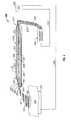
- FIG. 1is a side schematic view of an electrosurgical coagulator according to the present disclosure
- FIG. 1Ais an enlarged view of the encircled portion of FIG. 1 ;
- FIG. 2Ais an enlarged, schematic sectional view of an alternate embodiment of a gas cartridge for use with the electrosurgical coagulator of FIG. 1 having a color coded identification band and a safety valve;
- FIG. 2Bis an enlarged, schematic sectional view of a gas cartridge for use with the electrosurgical coagulator of FIG. 1 having a volume gauge and a refilling port;
- FIG. 2Cis an enlarged, schematic sectional view of a gas cartridge for use with the electrosurgical coagulator of FIG. 1 having a flow regulator;
- FIG. 3Ais a greatly-enlarged, schematic side view of an iris-like flow regulator for use with the electrosurgical coagulator of FIG. 1 ;
- FIG. 3Bis a cross sectional view of the iris-like flow regulator taken along line 3 B- 3 B of FIG. 3A ;
- FIG. 4is a side schematic view of an alternative embodiment of the electrosurgical instrument according to the present disclosure, showing an applicator and an actuator assembly;
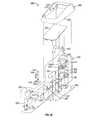
- FIGS. 5-5Bare perspective, side and frontal views of one embodiment of the actuator assembly of FIG. 4 ;
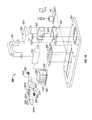
- FIGS. 6 and 6Aare perspective views with parts separated of the actuator assembly of FIG. 5 ;
- FIG. 7is a perspective view with parts separated of one embodiment of a gas source module in the actuator assembly
- FIG. 7Ais a side cross-sectional view of one embodiment of a gas supply coupler assembly according to the present disclosure.
- FIG. 7Bis a perspective view with parts separated of another embodiment of the gas source module in the actuator assembly.
- FIG. 8is a perspective view of the actuator assembly of FIG. 5 , with a foot pedal in an open position and showing the gas source module with a portable gas source in a disengaged position;
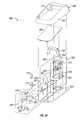
- FIG. 9is a perspective view of the actuator assembly of FIG. 5 , with the foot pedal in the open position and showing the gas source module with the portable gas source in an engaged position;
- FIG. 10is a perspective view of the interior of the actuator assembly of FIG. 8 , showing the gas source module with a portable gas source locking assembly and the gas source in the disengaged position;
- FIG. 11is a perspective view of the interior of the actuator assembly of FIG. 9 , showing the gas source module with the portable gas supply is in the engaged position and the portable gas source locking assembly locked;
- FIG. 12is a top view of the interior of the actuator assembly of FIG. 10 , showing a coupler assembly and corresponding portable gas supply in the disengaged position relative to the coupler assembly;
- FIG. 13is a top view of the interior of the actuator assembly of FIG. 11 , showing the coupler assembly and corresponding portable gas supply in the engaged position relative to the coupler assembly;
- FIG. 14is a perspective view of a cross-section of the actuator assembly of FIG. 5 , showing the foot pedal in the open position and the gas source module in the disengaged position;
- FIG. 15is a perspective view of a cross-section of the actuator assembly similar to FIG. 14 , showing the foot pedal in the open position and the gas source module in the engaged position;
- FIG. 16is a side cross-sectional view of the actuator assembly of FIG. 5 , showing the foot pedal in the open position and the gas source module in the disengaged position;
- FIG. 17is a side cross-sectional view of the actuator assembly of FIG. 5 , showing the foot pedal in the open position and the gas source module in the engaged position;
- FIG. 18is a side cross-sectional view of the actuator assembly of FIG. 5 , showing the foot pedal in a closed position and pads attached to the foot pedal used to actuate gas supply and energy controllers;
- FIG. 19is a side schematic view of an alternative embodiment of the electrosurgical instrument according to the present disclosure, showing a hand-held applicator with an actuator and the actuator assembly;
- FIG. 20is a perspective view with parts separated of the actuator assembly of FIG. 19 .
- FIG. 1shows one embodiment of a gas-enhanced electrosurgical instrument generally designated 10 having a self-contained supply of pressurized ionizable gas.
- FIGS. 4 and 19show different embodiments of gas-enhanced electrosurgical instruments generally designated 500 and 500 ′ having portable sources of pressurized ionizable gas remote from the hand-held applicator.
- the electrosurgical instruments of the present disclosuremay be used for various surgical functions, such as arresting bleeding tissue, desiccating surface tissue, eradicating cysts, forming eschars on tumors, or thermically marking tissue.
- the instrument described hereinis configured for use as a coagulator to arrest bleeding tissue.
- certain modificationscan be made to the electrosurgical instruments of the present disclosure so that the instruments can perform other surgical functions without departing from the scope of this disclosure.
- argonas the ionizable gas for promulgating coagulation of tissue
- another ionizable gas or a combination of ionizable gasesmay be utilized to achieve the desired result.
- coagulator 10is dimensioned to be pencil-like or hand-held, including robotically, for use during open surgical procedures, however, it is envisioned that a similar instrument or coagulator may be configured, for example, with a pistol grip or handle dimensioned for laparoscopic or endoscopic surgical procedures.
- a similar instrument or coagulatormay be configured, for example, with a pistol grip or handle dimensioned for laparoscopic or endoscopic surgical procedures.
- electrosurgical energyherein refers to any type of electrical energy which may be utilized for medical procedures.
- coagulator 10includes a frame, shown as an elongated housing 11 , having a proximal end 12 , a distal end 14 and an elongated cavity 15 extending therethrough, for supporting and/or housing a plurality of internal and/or external mechanical and electromechanical components thereon and therein.
- proximalwill refer to the end of coagulator 10 (or other element) which is closer to the user, while the term “distal” will refer to the end which is further from the user.
- Distal end 14 of housing 11includes a distal port 17 which is designed to emit, expel or disperse gas emanating from an elongated gas supply channel or tube 60 that in this embodiment runs generally longitudinally through frame or housing 11 of coagulator 10 .
- Tube 60is for supplying pressurized gas 50 to the proximity of an active electrode 350 located adjacent distal end 14 of housing 11 .
- Electrode 350is proximal of port 17 such that the gas that is emitted from port 17 is ionized.
- Elongated housing 11includes a receptacle 25 , typically positioned adjacent its proximal end 12 , which receptacle can be or be part of a unitary or integral handle portion 12 a of housing 11 .
- Receptacle 25is dimensioned to securely engage and receive or seat a gas pressurized container, canister, cartridge or cylinder 100 therein.
- Cylinder 100contains a surgical gas, e.g., a noble or inert gas, or mixture of noble or inert gases. References herein to inert gas or gases are understood to include noble gas or gases. The preferred inert gas is argon.
- Cylinder 100is relatively small, single use and disposable. The cylinder is of standardized design and certified for transportation requirements. Moreover, cylinder 100 is designed and/or sized to be incompatible with other commercial products such as whip cream dispensers and the like which use nitrogen and CO2 cartridges for other purposes. Details of gas cylinder 100 and its selective engagement with or connection to housing 11 are discussed in more detail below with respect to FIGS. 2A-2C .
- Elongated gas supply tube 60is adapted and dimensioned to channel or carry pressurized gas 50 from cylinder 100 through a regulator or valve 30 to or through distal end 14 of coagulator 10 for ionization, typically prior to the gas emitting and dispersing from distal port 17 .
- Regulator or valve 30can be part of or attached to cylinder 100 , housing 11 , or actuator 31 .
- distal port 17 or distal end 14may be configured to facilitate or promote the dispersion of the ionized gas plasma 50 ′ from distal port 17 in a uniform and consistent manner.
- distal end 14may be tapered on one, both or all sides thereof to direct the ionized plasma 50 ′ toward surgical or operative site 410 .
- distal port 17may be configured to disrupt or aggravate the dispersion or flow of gas plasma 50 ′ exiting distal port 17 to enhance coagulation by creating a more turbulent gas flow. It is contemplated that many suitable devices, e.g., screws, fans, blades, helical patterns, etc., may be employed to cause gas plasma 50 ′ to flow more or less turbulently or with other predetermined flow characteristics through tube 60 and/or out of distal port 17 .
- Elongated housing 11is connected, for example, by an electrical cable 310 , to a source of electrosurgical energy generally designated ESU, e.g., an electrosurgical generator 300 .
- proximal end 12includes a receptacle 25 which receives, securely engages and seats cylinder 100 therein.
- Receptacle 25 and/or cylinder 100need not be, as in the case of a single use disposable instrument, but may be configured to allow cylinder 100 to be selectively removable and replaceable within receptacle 25 . For example and as best shown in FIG.
- proximal end 12 of elongated housing 11 , or receptacle 25may include a locking mechanism 40 which upon insertion of a cylinder 100 into receptacle 25 automatically (or manually) releasably locks the cylinder 100 securely within receptacle 25 . By unlocking locking mechanism 40 , cylinder 100 may be removed and replaced with another cylinder 100 .
- the locking mechanism 40may be any suitable device or arrangement, e.g., a collar or clamp which provides adequate lever advantage to set the cylinder 100 against its end seal.
- the collar or clampmay be designed to allow the cylinder to be disengaged from the seal but retained within the receptacle 25 until the remaining pressurized gas is vented or otherwise relieved.
- the locking mechanism 40may include two or more opposing spring clamps 42 a , 42 b which mechanically engage a corresponding one or more notches or cut outs 120 a , 120 b formed in the outer surface of gas cylinder 100 .
- a locking mechanism 40 with spring clampscan be configured and adapted for releasably locking and quickly releasing the locking of cylinder 100 in receptacle 25 .
- the distal end 110 of cylinder 100 of FIG. 1 amay be configured, e.g., threaded (as shown as 110 ′ in FIG. 2A ) to threadedly engage valve 30 .
- the proximal end of cylinder 100 ′may include threads 120 ′ which threadably engage the interior of receptacle 25 (not shown). In this instance it may be advantageous to include or provide a rubber O-ring or washer in the proximity of the threads to protect against undesirable gas leakage.
- proximal end 12 of housing 11may be adapted to have an externally threaded collar or sleeve that extends axially outwardly and have an internally threaded screw closure cap.
- the screw closing of the capwould push cylinder 100 distally against the bias of a spring onto an axially disposed piercing member to thereby break the seal at the distal tip of the cylinder Removal of the closure cap would permit removal and replacement of the cylinder.
- the capcan be adapted to safely vent pressurized gas from the interior of the receptacle 25 should the seal on the distal end of the cylinder be lost or damages thus preventing the receptacle from bursting in the event of an internal overpressure.
- the capmay be configured to include a pressure regulator or valve to control flow through seal opening.
- this safety featuremay be designed to limit the flow from the cylinder and protect the user if the cylinder becomes damaged during handling.
- Other locking mechanismsare also envisioned, for example an over-the-center lever arrangement for pulling a yoke around the end of cylinder 100 , snap locks, spring locks on the cylinder 100 , locking levers, bayonet style locks, and locking dials or tabs, etc.
- the cylinder 100may also include various ergonomically friendly features such as rubber gripping elements or contoured walls to facilitate insertion into the housing 11 and handling especially during wet operative conditions. Additionally and as described in more detail below, the cylinder may be color coded to specify any or a combination of the following: cylinder contents (gas type and amount); initial pressure reading prior to activation; a specific flow rate; or specify use for a given procedure.
- Electrosurgical instrument 10includes at least one actuator, e.g., a dial or button, generally designated 31 , for actuating and selectively adjusting the flow of pressurized inert gas 50 from cylinder 100 to the proximity of active electrode 350 , and for actuating and selectively adjusting the delivery of electrosurgical energy from the source, i.e., from generator 300 , to the active electrode 350 for ionizing the inert gas for use at the surgical site 410 .
- Actuator 31can also operate as the actuator for actuating delivery of electrosurgical energy from the source.
- Actuator 31may be referred to herein as the first actuator. It is envisioned that instead of being located in housing 11 , one or more of the actuators, regulators and/or valves described herein may be located in a foot switch appropriately connected to coagulator 10 .
- Electrosurgical instrument or coagulator 10can also include a second actuator, here shown as a button-like trigger 20 , for actuating the delivery of electrosurgical energy from the source, e.g., from generator 300 , through cable 310 and leads 322 , 330 to the active electrode 350 for ionizing the inert gas for use at the surgical site 410 .
- Trigger 20can be attached to or mounted, for example, on or atop or through elongated housing 11 .
- Trigger 20may be any type of known trigger, e.g., a rocker switch, a handswitch, a footswitch, a slide switch, a dial, a button, a lever, etc., which, upon actuation thereof, electrically communicates with electrosurgical generator 300 to allow the selective delivery of electrosurgical energy to active electrode 350 .
- a rocker switche.g., a handswitch, a footswitch, a slide switch, a dial, a button, a lever, etc.
- Active electrode 350can be attached to or mechanically engaged with the distal end of the housing and positioned adjacent to or at an operating site 410 .
- Active electrode 350is positioned adjacent the distal end of frame or housing 11 between the distal end of tube 60 and distal port 17 , although the active electrode can be located just to the exterior of port 17 .
- active electrode 350can be mounted to an elongated member that is supported within housing 11 and that extends outside of the housing, such that the electrode is positioned just outside of the port. Active electrode 350 need not be as shown.
- Itcan be a conductive elongated member in the form of a blade, needle, snare or ball electrode that extends from an electrosurgical instrument and that is suitable, for example, for fulguration, i.e., coagulation, cutting or sealing tissue.
- a return electrode or pad 370is typically positioned under the patient and connected to a different electrical potential on electrosurgical generator 300 via cable 360 . During activation, return pad 370 acts as an electrical return for the electrosurgical energy emanating from electrosurgical coagulator 10 . It is envisioned that various types of electrosurgical generators 300 may be employed for this purpose, such as those generators sold by Valleylab, Inc.—a division of Tyco Healthcare Group LP, of Boulder, Colo.
- trigger 20upon actuation thereof is designed to energize electrode 350 in a simple “on/off” manner, e.g., when the trigger is depressed (or otherwise moved or manipulated, e.g., twisted (dial switch), rocked (rocker switch), or slid (slide switch)).
- the electrical intensity from generator 300may be selectively regulated by trigger 20 , such that the user can alter the electrosurgical effect at operative site 410 .
- a pressure sensitive trigger or regulatormay be utilized to control the amount of electrosurgical energy that is conducted to electrode 350 which, as described below with respect to the operation of coagulator 10 , effects coagulation of tissue 400 .
- Triggers and actuatorsthat are contemplated include those such as described in commonly-owned U.S. Provisional Application Ser. No. 60/424,352 and commonly-owned U.S. application Ser. No. 10/251,606, the entire contents of each of which are incorporated by reference herein, without intention of being limited to the same.
- U.S. application Ser. No. 10/251,606, now publication No. 04-0092927discloses an electrosurgical instrument having variable controls, a housing, and an electrocautery blade or electrode extending from the housing and connected to a source of electrosurgical energy.
- An actuator button supported on the housingis movable, e.g., depressed, or rocked or slid, from a first position to at least a subsequent position, preferably to a series of discrete subsequent positions wherein each subsequent position corresponds to a specific amount of energy being transmitted to the blade.
- a transducere.g., a pressure transducer, or other suitable circuit element, is electrically connected between the activation button and the source of electrosurgicai energy.
- the transduceris configured to transmit an electrical output signal (or a range of output signals) to the energy source correlating to the selected movement or position(s) of the activation button.
- the sourcecorrespondingly supplies an amount or range of electrosurgical energy emission to the blade dependent upon the electrical output signal(s).
- the above actuator and selectively adjustable systemcan be employed using at least one actuator, actuator 31 , for actuating and selectively adjusting the flow of pressurized gas from cylinder 100 , e.g., via regulator and valve 30 , and for actuating and selectively adjusting delivery of energy from the source.
- actuator 31for actuating and selectively adjusting the flow of pressurized gas from cylinder 100 , e.g., via regulator and valve 30 , and for actuating and selectively adjusting delivery of energy from the source.
- Suchcan be achieved by employing, for example, a suitable transistor that produces a signal or two signals or different sets of output signals based on movement of the actuator button.
- the signal(or one signal or set of signals) is sent to and is suitable for actuating actuator 31 or regulator and valve 30 to actuate movement-correlated corresponding selectively adjusted flow of gas from the cylinder.
- the signal (or the other signal or set)is sent to and is suitable for actuating trigger 20 to deliver energy from the source.
- a similar suitable actuator systemcan be employed with one transistor to actuate a first actuator, actuator 31 , for actuating and selectively adjusting the flow from cylinder 100 , and a second transistor to actuate a second actuator, trigger 20 , for actuating and selectively adjusting delivery of energy from the source. It is envisioned that instead of being located in housing 11 , trigger 20 can be located in a foot switch appropriately connected to electrosurgical generator 300 and coagulator 10 .
- the at least one actuatore.g., actuator 31
- the instrument or coagulatorincludes one or more elements, e.g., circuitry, or mechanical or electromechanical mechanism(s), for timing the flow of gas from cylinder 100 and the delivery of energy to the electrode.
- the first actuatoris activated prior to the activation of the second actuator.
- trigger 20may cooperate with one or more sensors 365 which can be attached to instrument 10 , housing 11 or electrode 350 and which, for example, continually measures or monitors a condition at operative site 410 , e.g., the amount of tissue coagulation, and relays the information back to generator 300 or trigger 20 .
- a control system or a safety circuitmay be employed which automatically (e.g., through a shut-off switch) reduces pressure or partially closes valve 30 if an obstruction is indicated.
- the safety circuitmay be configured to cut off the energy to tissue 400 and/or activate or release a pressure relief valve (e.g., a safety release valve generally designated 367 ) to release the pressure of the pressurized gas based upon a sensed condition (e.g., an embolic condition or concern) by a sensor 365 or by the surgeon.
- a pressure relief valvee.g., a safety release valve generally designated 367
- gas cylinder 100e.g., by valve 30
- valve 30can be partially modulated, inactivated, ejected (or released) from engagement with valve coupling 32 , or valve 30 may be automatically fully de-activated or closed.
- sensor 365may provide feedback to trigger 20 or generator 300 to optimize coagulation of the tissue 400 based upon distance from the tissue deduced from the measured back pressure in supply tube 60 , based upon tissue type or based upon tissue response.
- a second sensor 321may be employed to measure the flow of gas 50 through gas supply tube 60 , and may be electrically connected to a flow regulator, e.g., valve 30 , to automatically regulate the flow of gas from cylinder 100 to electrode 350 .
- actuator 31includes regulator and valve 30 which is mounted to and through elongated housing 11 and which can be dimensioned to mechanically engage (and preferably also puncture or otherwise engage and open) the sealed outlet at distal end 110 of selectively removable gas cylinder 100 .
- Gas cylinder 100can be removable in a reusable or disposable version of the instrument.
- the mechanical engagement and securement of gas cylinder 100 and valve 30involves a quick-release type mechanism or other simple attachment mechanism which can be employed on and/or or as part of cylinder 100 , receptacle 25 and/or housing 11 to enable the user to quickly and accurately engage and disengage and remove and replace gas cylinder 100 .
- locking mechanism 40may be employed to permanently or releasably secure cylinder 100 within receptacle 25 .
- Actuation of actuator 31activates regulator and valve 30 .
- Regulator and valve 30selectively controls or regulates the flow of gas from cylinder 100 to electrode 350 .
- Regulator and valve 30may include a cylinder interface or coupling 32 and a plenum 34 .
- Actuator 31 or regulator and valve 30selectively adjusts plenum 34 to selectively regulate the amount or flow of gas 50 from gas cylinder 100 , to supply tube 60 and to electrode 350 .
- actuator 31may be incrementally adjustable (i.e., rotatable, slideable or pressure sensitive) to provide tactile feedback to the user relating to the flow of gas 50 .
- plenum 34is disposed between the regulator portion of the regulator and valve 30 and the proximal end 62 of supply tube 60 .
- coupling 32mechanically engages (e.g., threadably engages, snap fits, friction-fits, slide fits, spring mounts, bayonets, or otherwise) cylinder 100 , seals the juncture with cylinder 100 , and also breaks, pierces or otherwise opens the sealed distal end or outlet of cylinder 100 upon insertion of the cylinder 100 into receptacle 25 .
- regulator and valve 30can include actuator 31 .
- Regulator and valve 30may be referred to herein as a first flow regulator for selectively regulating the flow of pressurized gas from cylinder 100 .
- coagulator 10can include separate pressure regulators, valves and/or flow regulators which are separated and spaced down the length of the coagulator 10 .
- a second flow regulatore.g., “FR2” may be included which selectively regulates the flow of pressurized gas to electrode 350 .
- coagulator 10can include a pressure regulator, e.g., “PR”, for regulating the pressure of the pressurized gas that flows to electrode 350 .
- Valve 30may include a pressure regulator having a pressure relief valve in communication with cylinder 100 for regulating and/or relieving the pressure of the pressurized gas in the cylinder.
- Coagulator 10also may include a flow limiter.
- valve 30may include a flow limiter for limiting the flow of pressurized gas to electrode 350 to a selected level.
- a pressure relief valve or “burp valve”may be included which is disposed proximal to the flow limiter or plenum to permit gas to escape from the channel 60 thereby preventing a build-up of pressure at opening 17 as a result of partial of full occlusion of opening 17 .
- a flue 430(see FIG. 1 ) may be included which transfers the relieved gas flow to the proximal end of the coagulator 10 .
- Distal end 110 of cylinder 100is hermetically sealed when and after it is mounted to and mechanically engaged with coupling 32 to avoid undesirable gas leakage from the mechanical connection.
- the end sealmay be formed through metal-to-metal contact, by an elastomeric land at the face 110 of cylinder 100 or an elastomeric ring encircling cylinder 100 .
- various rubber seals, gaskets, flanges or the likemay be employed to accomplish this purpose.
- valve 30be opened, e.g., manually, to a desired flow rate prior to activation of electrode 350 to ionize the plasma to coagulate tissue 400 .
- the same button, actuator or lever that actuates the delivery of energywould also activate regulator and valve 30 and the flow of gas.
- the movement of a leverwould actuate regulator and valve 30 and the flow of gas prior to continued movement of the lever to actuate delivery of energy from the generator 300 .
- actuator 31 or valve 30may be automatically regulated to communicate with trigger 20 and be automatically controlled by activation of trigger 20 .
- the usermay select a flow rate by actuating actuator 31 (which may include a visual indicator or the like to allow the user to readily determine flow rate) such that upon actuation of trigger 20 , regulator and valve 30 initiates the flow of gas 50 through tube 60 to the an ignition point 355 proximate electrode 350 .
- Electrode 350can, in turn, be activated to ionize the gas 50 and force the ionized gas plasma 50 ′ at the tissue or operating site 410 .
- actuation of actuator 31 or regulator and valve 30can automatically activate actuation of trigger 20 and flow of electrosurgical energy to electrode 350 .
- the ignition of the electrode 350is delayed either mechanically, electro-mechanically or utilizing delay circuitry or a delay algorithm to preferably enhance delivery of plasma 50 ′ to operating site 410 .
- the delay circuitry or algorithmmay be incorporated in trigger 20 , valve 30 or generator 300 .
- ionizable gas 50is supplied under pressure from gas cylinder 100 to regulator and valve 30 (or simply a flow regulator) and, upon selective actuation of actuator 31 , the gas flows to ignition point 335 near electrode 350 where gas 50 is ionized into a gas plasma 50 ′ before being distributed, dispersed or dispensed out of distal end 17 to operating site 410 .
- the usermay selectively alter the gas flow rate and/or the intensity of the energy emanating from electrode 350 to meet a desired surgical effect.
- Gas cylinder 100is relatively small and contains an appropriate or sufficient amount gas 50 for a given surgery of short duration. Cylinder 100 is typically for single use, and is disposable. It may be replaced as needed during the surgical procedure if it requires a longer or different gas application than provided by a single gas cylinder. As can be appreciated, different gas cylinders 100 may be utilized for different surgeries which have different gas requirements, e.g., in terms of types, amounts, pressures and/or flow rates. The gas pressure of cylinders 100 is typically about 3000 psi or less. Gas cylinders 100 have a volume of about 100 cc's or less.
- Cylinders 100 containing about 4 liters of gas and a flow time of about 2 minuteshave been found suitable for a typical coagulation procedure.
- the flow rate provided by the cylindercan range from about 0.2 liters/min. to about 4 liters/min, and the nominal flow rate may be about 2 liters /min.
- cartridge 100may be preconfigured to deliver gas at a predefined flow rate, and coagulator 10 may be configured without a flow regulator or flow valve 30 in or on elongated housing 11 .
- elongated housing IImay simply include an “open” and “close” switch (not shown) which blocks or releases the flow of gas from the gas cylinder 100 depending upon the position of the switch. As a result thereof, when opened, coagulator 10 relies on the predetermined flow rate of the gas 50 exiting the gas cylinder 100 under pressure.
- the gas flow rate employedis dependent upon factors such as the instrument being used and/or the type of surgery or procedure to be performed.
- Different gas cartridgese.g., cylinder 100 ′
- a usermay pick the appropriate color which specifically relates to a desired specific gas, flow rate and intended surgical use.
- Cylinder 100may include a knob, e.g., 100 a at the proximal end of the cylinder to facilitate manipulation of the cylinder.
- FIG. 2Ashows an embodiment of a gas cylinder 100 ′ which includes a safety release pressure stop valve 188 ′ which is designed to automatically prevent flow of gas from, cylinder 100 ′ when the cylinder is removed. More particularly, upon release of the cylinder 100 ′ from coupling 32 , a ball 189 ′ (in a ball check valve) or some other movable obstruction automatically moves distally to block the passage of gas 50 through distal end 110 ′ of the cylinder 100 ′. Upon insertion or engagement of the cylinder 100 ′ into coupling 32 , a pin or other protruding element (not shown) forces ball 189 ′ proximally to allow the release of gas 50 from cylinder 100 ′.
- a safety release pressure stop valve 188 ′which is designed to automatically prevent flow of gas from, cylinder 100 ′ when the cylinder is removed. More particularly, upon release of the cylinder 100 ′ from coupling 32 , a ball 189 ′ (in a ball check valve) or some other movable obstruction automatically moves
- release pressure stopsmay be employed to accomplish the same or similar purpose and the above-described release pressure stop valve 188 ′ is only one example.
- cylinder 100 or the likee.g., 100 ′′′
- coagulator 10e.g., receptacle 25
- coagulator 10can include a pressure relief valve 440 in communication with cylinder 100 for relieving the pressure of the pressurized gas in the cylinder.
- an embodiment of gas cylinder 100 ′′may include a gauge 185 ′′ which measures and indicates the amount of pressurized gas left in cylinder 100 ′′ at any given time.
- a visual or audible indicator or sensor(not shown) may be employed to alert the user of a low gas condition.
- Gas cylinder 100 ′′may also include a fill port or refill valve 160 ′′ which enables the user to selectively refill interior 170 ′′ of gas cylinder 100 ′′ without removing the cylinder from within receptacle 25 of instrument 10 .
- FIG. 2Cshows another embodiment of gas cylinder 100 ′′′, which includes a valve 180 ′′′ disposed thereon which allows a user to selectively regulate gas flow from interior chamber 170 ′′′ through distal end 110 ′′′ and to coagulator 10 .
- a valvewould not necessarily be needed within coagulator 10 and the user can selectively regulate gas 50 by rotating (or otherwise adjusting) valve 180 ′′′ as needed.
- FIGS. 3A and 3Bshow an embodiment of a flow control valve, here shown as a rotary iris-like valve 30 ′, which may be utilized within coagulator 10 (or with the gas cylinder 100 ′′′ as mentioned above) for selectively controlling the flow of pressurized gas from the cylinder.
- Iris valve 30 ′may be disposed between a coupling 32 ′ and a flared portion 62 ′ of proximal end 62 of supply tube 60 .
- a series of interleaved portions 31 a - 31 gmove to radially reduce or condense the dimensions of passageway or opening 37 to limit gas flow therethrough and to the flared portion 62 ′ of gas supply tube 60 .
- the interleaved portions 31 a - 31 gmove to radially expand the dimensions of opening 37 , enhancing gas flow therethrough and to the flared portion 62 ′ of the supply tube 60 .
- a corona return electrode or corona start electrodemay be utilized with electrode 350 to initiate a plasma arc.
- the corona return electrodemay be placed on or within housing 11 located near distal end 14 or distal port 14 .
- the corona return electrodeis electrically connected to return path 360 of electrosurgical generator 300 .
- the function of the corona return electrodeis to establish a non-uniform electrical field with active electrode 350 .
- the non-uniform electric fieldwill cause the formation of a corona near active electrode 350 , which will thereby aid in the ignition of gas 50 as it flows out of distal port 17 of the housing 11 .
- a dielectric member(not shown) may be positioned to separate active electrode 350 from the corona return electrode.
- the coagulator 10may be configured to include a two-stage regulator (not shown) instead of a burp valve.
- thismay be particularly advantageous for use with a laparoscopic device wherein the gas flow may be affected by insufflation pressure in the operating cavity.
- the electrosurgical instrumentmay include a pistol grip-like handle which enables the user to handle the instrument like a pistol. It is also contemplated that the cylinder may be dimensioned for selective engagement (i.e., insertion) within and disengagement (i.e., release) from the handle. Alternatively, the handle may be selectively pivotable for handling the electrosurgical instrument in different orientations, e.g., from an offset position relative to the housing for handling the electrosurgical instrument in pistol-like fashion to a generally aligned orientation for handling the electrosurgical instrument like a pencil.
- electrosurgical instrumentWhile several embodiments of the electrosurgical instrument described above show an internally mounted cylinder 100 that fits within receptacle 25 of housing 11 , it is envisioned that a portable gas supply may be used to accomplish the same purpose.
- a portable gas supplyis provided in a remote actuator assembly 550 , here a foot actuator assembly used by the surgeon.
- the remote actuator assemblycould be a hand operated actuator that is used by another person attending the surgical procedure, such as a nurse.
- the surgical instrument 500 in this embodimentincludes a hand-held applicator 510 and actuator assembly 550 .
- the hand-held applicator 510includes a frame, shown as an elongated housing 514 , having a proximal end 516 , a distal end 518 and an elongated cavity 520 extending therethrough.
- Distal end 518 of housing 514includes a distal port 522 which is designed to emit, expel or disperse gas emanating from an elongated gas delivery member (here a channel or tube) 524 that in this embodiment runs generally longitudinally through frame or housing 514 of applicator 510 .
- Tube 524extends from the proximal end 516 of housing 514 for connection to supply tube 552 connected to actuator assembly 550 .
- Tube 524is for supplying pressurized gas 50 to the proximity of an active electrode 350 located adjacent distal end 518 of housing 514 .
- Electrode 350is proximal of port 522 such that the gas that is emitted from port 522 is ionized.
- a connector 517is provided at the other end of the housing 514 , i.e., its proximal end 12 so that hand-held applicator 510 can be connected to the actuator assembly 550 and, for example, a source of electrosurgical energy, such as electrosurgical generator 300 , via electrical cable 575 .
- a source of electrosurgical energysuch as electrosurgical generator 300
- active electrode 350can be attached to or mechanically engaged with the distal end of the housing and positioned adjacent to or at an operating site 410 .
- Electrode 350is positioned adjacent the distal end of frame or housing 514 between the distal end 525 of tube 524 and distal port 522 , although the electrode can be located just to the exterior of port 522 .
- electrode 350can be mounted to an elongated member that is supported within housing 514 and that extends outside of the housing, such that the electrode is positioned just outside of the port. Like the embodiment of FIG. 1 , electrode 350 need not be as shown.
- Itcan be a conductive elongated member in the form of a blade, needle, snare or ball electrode that extends from an electrosurgical instrument and that is suitable, for example, for fulguration, i.e., coagulation, cutting or sealing tissue.
- a return electrode or pad 370is typically positioned under the patient and connected to a different electrical potential on electrosurgical generator 300 via cable 360 . During activation, return pad 370 acts as an electrical return for the electrosurgical energy emanating from hand-held applicator 510 . It is envisioned that various types of electrosurgical generators 300 may be employed for this purpose, such as those generators sold by Valleylab, Inc.—a division of Tyco Healthcare Group LP, of Boulder, Colo.
- distal port 522 or distal end 518 of applicator 510may be configured to facilitate or promote the dispersion of the ionized gas plasma 50 ′ from distal port 522 in a uniform and consistent manner.
- the distal end 518may be tapered on one or all sides to direct the ionized plasma 50 ′ toward the surgical or operative site 410 .
- distal port 522may be configured to disrupt or aggravate the dispersion or flow of gas plasma 50 ′ exiting distal port 522 to enhance coagulation by creating a more turbulent gas flow.
- gas plasma 50 ′may be employed to flow more or less turbulently or with other predetermined flow characteristics through tube 524 and/or out of distal port 522 .
- the hand-held applicatormay include a pistol grip-like handle which enables the user to handle the applicator like a pistol.
- the handlemay be selectively pivotable for handling the hand-held applicator in different orientations, e.g., from an offset position relative to the housing for handling the applicator in pistol-like fashion to a generally aligned orientation for handling the applicator like a pencil.
- the actuator assembly 550includes a housing 560 having a cover 562 connected to base 564 .
- Cover 562has an actuator 566 , which in this embodiment is a foot pedal pivotably secured to bracket 567 (See FIG. 6 ), used to actuate one or more controllers and to puncture the outlet of the gas supply.
- actuator 566which in this embodiment is a foot pedal pivotably secured to bracket 567 (See FIG. 6 ), used to actuate one or more controllers and to puncture the outlet of the gas supply.
- there are two controllersone used to control the gas supplied to applicator 510 and the other used to control the electrosurgical energy supplied to applicator 510 .
- controllers 568 and 570are secured to a mounting plate 572 which, in turn, is secured to base 564 .
- Actuation of controller 568is designed to energize electrode 350 in a simple “on/off” manner, e.g., when the controller is actuated (e.g., depressed or otherwise moved or manipulated) electrosurgical energy is supplied to the electrode 350 .
- Actuation of controller 570is designed to allow gas to flow from actuator assembly 550 to applicator 510 (See FIG. 6 ) for discharge to the operative site 410 .
- Controller 570is preferably an open and close type valve that permits or blocks the flow of the pressurized gas.
- controller 570When using this type of controller 570 the pressure of the gas in the cylinder 581 is the pressure of the gas supplied to applicator 510 .
- controller 570may be a regulator/valve assembly that selectively controls and/or regulates the flow of gas from cylinder 581 to applicator 510 .
- controller 570may be an adjustable valve that controls the flow of pressurized gas with a rotatable knob, slidable lever or pressure sensitive pad extending from housing 560 .
- the controller 570may also provide the user with tactile or audible feedback that is indicative of the flow of gas.
- Housing 560also houses a gas source module 580 that holds a portable source of pressurized ionizable gas for the surgical procedure being performed.
- Gas source module 580includes a receptacle 582 configured to securely engage, receive, seat or otherwise hold a source of pressurized ionizable gas and to move the gas source between a disengaged position shown in FIG. 10 and an engaged position shown in FIG. 11 .
- the gas source shownis a cylinder 581 containing pressurized ionizable gas.
- the cylinder 581 shownis similar to the cylinders 100 , 100 ′, 100 ′′ and 100 ′′′ described above.
- actuator assembly 550may be larger than the applicator 510 , larger or longer pressurized containers, canisters, cylinders or cartridges may be employed to provide more pressurized gas during prolonged use. Details of the engagement of cylinder 581 in the actuator assembly 550 are discussed in more detail below with reference to FIGS. 8-18 .
- receptacle 582includes a pair of groves 586 that fit onto rail 588 secured to base 564 so that cylinder 581 is movable between the disengaged and engaged positions.
- a gas source locking assembly 590is provided to facilitate movement of receptacle 582 and to lock the receptacle in place when the cylinder 581 is in the engaged position so as to maintain sufficient pressure on the receptacle 582 (and thus the cylinder 581 ) to ensure that the outlet of the cylinder is sealed in coupler assembly 598 and pressurized gas is prevented from leaking into the housing.
- Locking assembly 590includes pivot arm mount 592 secured to base 564 , pivot arm 594 pivotably secured at one end 594 a to mount 592 and pivotably secured to locking arm 596 at end 594 b . End 596 a of locking arm 596 is pivotably secured to receptacle 582 as shown.
- the locking assembly 590may be a ratchet mechanism where receptacle 582 includes a series of grooves 620 on one or both sides and one or more teeth 622 configured to engage the groves 620 and lock the receptacle in position are provided on pivotable arms 624 .
- Spring 626normally biases ends 624 a of arms 624 away from each other so that the teeth 622 move toward each other.
- Springs 628 supported by pins 630 on arms 624engage inner walls of the housing 560 and assist spring 626 in normally biasing the teeth 622 toward each other.
- ends 624 a of arms 624which partially extend outside from housing 560 are manually pressed or crimped so that springs 626 and 628 are compressed and ends 624 b of arms 624 spread apart.
- the gas source module 580also includes a coupler assembly 598 configured to engage the outlet of the cylinder 581 and provide a hermetic seal around the outlet of the cylinder so that gas does not escape from the coupler assembly.
- Coupler assembly 598includes a coupler 600 secured within housing 602 secured to base 564 .
- Coupler 600may be constructed of an elastomeric material so that when the outlet of cylinder 581 is pressed into port 604 (seen in FIG. 7A ) of coupler 600 a hermetic seal forms around the outlet of the cylinder.
- the interior of port 604has a pin 606 used to break, rupture or puncture the seal on the outlet when a new cylinder is first moved to the engaged position as will be described below.
- Coupler 600also has a channel 608 and an exit port 610 that connects to tube 612 connected to controller 570 (seen in FIG. 12 ).
- actuator assembly 550may cooperate with one or more sensors 365 that can be attached to housing 514 of applicator 510 or electrode 350 (seen in FIG. 4 ).
- sensors 365can be used to continually measure or monitor a condition at the operative site 410 , e.g., the amount of tissue coagulation, and relay the information back to generator 300 or actuator assembly 550 .
- a control system or safety circuit(not shown) may be employed to automatically (e.g., through a shut-off switch) reduce gas pressure or partially actuate controller 570 of actuator assembly 550 if an obstruction is detected.
- the safety circuitmay be configured to cut off the electrosurgical energy to tissue 400 (via electrode 350 ) and/or activate or release a pressure relief valve (e.g., a safety release valve generally designated 367 ) to change the pressure of the gas discharged from the distal end 522 of the applicator 510 in response to a condition (e.g., an embolic condition or concern) sensed by sensor 365 or by the surgeon.
- a pressure relief valvee.g., a safety release valve generally designated 367
- pressure release valve 367may be depressed or rotated into housing 514 to constrict supply tube 524 and reduce the volume of gas discharged from the distal end 522 of applicator 510 .
- controller 570may be automatically deactivated or closed.
- sensor 365may provide feedback to actuator assembly 550 or generator 300 to optimize performance of the surgical function, here coagulation of the tissue 400 , based upon, for example, 1) the distance of the applicator 510 from the tissue deduced from the measured back pressure in supply tube 524 , 2) tissue type, or 3) tissue response.
- a second sensor 321may be employed to measure the flow of gas 50 through gas supply tube 524 , and may be electrically connected to a flow regulator (not shown) to automatically regulate the flow of gas from cylinder 581 to electrode 350 .
- FIGS. 8-18the operation of the applicator 510 and actuator assembly 550 to supply ionized gas to the operative site 410 will be described.
- the actuator 566Prior to or at the beginning of the surgical procedure the actuator 566 is lifted (seen in FIG. 8 ) and a sealed portable source of pressurized ionizable gas, e.g. cylinder 581 , is inserted into receptacle 582 of gas source module 580 .
- a sealed portable source of pressurized ionizable gase.g. cylinder 581
- the gas source module 580is in a retracted position where the outlet of the cylinder 581 is not engaged with coupler 600 of coupler assembly 598 .
- locking arm 596 of locking assembly 590when in the disengaged position, locking arm 596 of locking assembly 590 is in a retracted position (seen in FIGS. 14 and 16 ) so that end 596 b of the locking arm extends from housing 560 and receptacle 582 is retracted along rail 588 so that the outlet of cylinder 581 is positioned away from coupler 600 .
- end 596 b of locking arm 596is pushed, preferably in the direction of arrow A (seen in FIG. 16 ), so that receptacle 582 slides along rail 588 in the direction of arrow B (seen in FIG. 17 ) towards coupler assembly 598 and the outlet of cylinder 581 enters port 604 of coupler 600 .
- actuator 566can pivot to a closed position (seen in FIG. 18 ).
- the seal on the sealed portable source of pressurized ionizable gase.g., cylinder 581
- the userfirsts applies sufficient pressure to actuator 566 so that pressure pads 565 attached to actuator 566 engage end 596 b of locking arm 596 causing the receptacle to further move along rail 588 so that the outlet of cylinder 581 is pressed against pin 606 in coupler 600 to puncture the seal.
- end 596 b of locking arm 596rests against mount 592 , as shown in FIG. 11 , so that the outlet of cylinder 581 is sealed within coupler 600 .
- pressurized gaspasses through channel 608 in coupler 600 and exits the coupler via exit port 610 (See FIGS. 10-13 ). Pressurized gas then passes through tube 612 to controller 570 .
- pad 569 attached to actuator 566engages controller 570 (as seen in FIGS. 12 and 18 ) and actuates the controller causing pressurized gas to flow through tube 614 to port 572 in housing 562 and exit the actuator assembly 550 .
- pad 571 attached to actuator 566engages controller 568 (as seen in FIG. 18 ) and actuates the controller causing energy to flow from connector 574 to the electrode 350 in the applicator 510 .
- Connector 574is a conventional electrical connector used to electrically connect the actuator assembly 550 to the cable 575 .
- pads 569 and 571can be dimensioned such that a first level of pressure causes pad 569 to actuate controller 570 and a second level of pressure causes pad 571 to actuate controller 568 so that pressurized gas is provided to applicator 510 prior to electrosurgical energy being supplied to electrode 350 .
- pads 569 and 571can be dimensioned so that pressurized gas and electrosurgical energy are supplied to the applicator 510 at the same time.
- the actuator assembly 550 ′includes the controller 570 for controlling the flow of pressurized gas to the applicator 510 ′, and the hand-held applicator includes the controller 568 that controls the energy supplied to the electrode 350 .
- the cable 575 between the applicator 510 ′ and the actuator assembly 550 ′is not needed and the electrical connections for this embodiment are similar to those described above with respect to FIG. 1 .
- Operation of the actuator assemblyis similar to the operation described above, except for the description of controller 568 which is not included in this embodiment.
- electrosurgical instrument pressurized gasis provided upon actuation of the controller 570 in actuator assembly 550 ′ and electrosurgical energy is supplied to the electrode upon actuation of controller 568 in hand-held applicator 510 ′.
- gas supply hose 552may be attached to the electrosurgical cable 575 which attaches to the proximal end of the applicator 510 to limit tangling.
- the electrosurgical instrumenti.e., the applicator and actuator assembly
- the source of pressurized ionizable gase.g., cylinder 581
- the electrosurgical instrumentmay be completely disposable or the electrosurgical instrument may be reposable and the gas source disposable.
- the mechanically engaging end of the gas sourcemay be designed for easy retrofit onto exiting electrosurgical instruments.
- the applicator 510 and/or 510 ′can include a second flow regulator (not shown) to regulate the flow of pressurized gas to electrode 350 .
- argonas the ionizable gas for promulgating coagulation of the tissue
- another ionizable gas or a combination of ionizable gasesto effect the same or a similar or different result.
Landscapes
- Health & Medical Sciences (AREA)
- Surgery (AREA)
- Engineering & Computer Science (AREA)
- Life Sciences & Earth Sciences (AREA)
- Biomedical Technology (AREA)
- Otolaryngology (AREA)
- Nuclear Medicine, Radiotherapy & Molecular Imaging (AREA)
- Plasma & Fusion (AREA)
- Physics & Mathematics (AREA)
- Heart & Thoracic Surgery (AREA)
- Medical Informatics (AREA)
- Molecular Biology (AREA)
- Animal Behavior & Ethology (AREA)
- General Health & Medical Sciences (AREA)
- Public Health (AREA)
- Veterinary Medicine (AREA)
- Surgical Instruments (AREA)
Abstract
Description
Claims (13)
Priority Applications (1)
| Application Number | Priority Date | Filing Date | Title |
|---|---|---|---|
| US12/503,738US8226644B2 (en) | 2004-02-03 | 2009-07-15 | Gas-enhanced surgical instrument |
Applications Claiming Priority (4)
| Application Number | Priority Date | Filing Date | Title |
|---|---|---|---|
| US54132604P | 2004-02-03 | 2004-02-03 | |
| US11/048,577US7628787B2 (en) | 2004-02-03 | 2005-02-01 | Self contained, gas-enhanced surgical instrument |
| US11/229,814US7572255B2 (en) | 2004-02-03 | 2005-09-19 | Gas-enhanced surgical instrument |
| US12/503,738US8226644B2 (en) | 2004-02-03 | 2009-07-15 | Gas-enhanced surgical instrument |
Related Parent Applications (1)
| Application Number | Title | Priority Date | Filing Date |
|---|---|---|---|
| US11/229,814ContinuationUS7572255B2 (en) | 2004-02-03 | 2005-09-19 | Gas-enhanced surgical instrument |
Publications (2)
| Publication Number | Publication Date |
|---|---|
| US20090275941A1 US20090275941A1 (en) | 2009-11-05 |
| US8226644B2true US8226644B2 (en) | 2012-07-24 |
Family
ID=43599641
Family Applications (2)
| Application Number | Title | Priority Date | Filing Date |
|---|---|---|---|
| US11/229,814Active2026-11-02US7572255B2 (en) | 2004-02-03 | 2005-09-19 | Gas-enhanced surgical instrument |
| US12/503,738Expired - Fee RelatedUS8226644B2 (en) | 2004-02-03 | 2009-07-15 | Gas-enhanced surgical instrument |
Family Applications Before (1)
| Application Number | Title | Priority Date | Filing Date |
|---|---|---|---|
| US11/229,814Active2026-11-02US7572255B2 (en) | 2004-02-03 | 2005-09-19 | Gas-enhanced surgical instrument |
Country Status (1)
| Country | Link |
|---|---|
| US (2) | US7572255B2 (en) |
Cited By (2)
| Publication number | Priority date | Publication date | Assignee | Title |
|---|---|---|---|---|
| US10463418B2 (en) | 2010-07-22 | 2019-11-05 | Plasma Surgical Investments Limited | Volumetrically oscillating plasma flows |
| US11882643B2 (en) | 2020-08-28 | 2024-01-23 | Plasma Surgical, Inc. | Systems, methods, and devices for generating predominantly radially expanded plasma flow |
Families Citing this family (21)
| Publication number | Priority date | Publication date | Assignee | Title |
|---|---|---|---|---|
| US6616660B1 (en) | 1999-10-05 | 2003-09-09 | Sherwood Services Ag | Multi-port side-fire coagulator |
| US6475217B1 (en)* | 1999-10-05 | 2002-11-05 | Sherwood Services Ag | Articulating ionizable gas coagulator |
| US7572255B2 (en)* | 2004-02-03 | 2009-08-11 | Covidien Ag | Gas-enhanced surgical instrument |
| US8226643B2 (en)* | 2004-02-03 | 2012-07-24 | Covidien Ag | Gas-enhanced surgical instrument with pressure safety feature |
| US8083735B2 (en) | 2006-11-17 | 2011-12-27 | Genii, Inc. | Compact electrosurgery apparatuses |
| US9656095B2 (en) | 2007-04-23 | 2017-05-23 | Plasmology4, Inc. | Harmonic cold plasma devices and associated methods |
| US9257264B2 (en) | 2007-04-23 | 2016-02-09 | Plasmology4, Inc. | Harmonic cold plasma devices and associated methods |
| US20090076505A1 (en)* | 2007-09-13 | 2009-03-19 | Arts Gene H | Electrosurgical instrument |
| US8994270B2 (en) | 2008-05-30 | 2015-03-31 | Colorado State University Research Foundation | System and methods for plasma application |
| US20100042088A1 (en)* | 2008-08-14 | 2010-02-18 | Arts Gene H | Surgical Gas Plasma Ignition Apparatus and Method |
| US8226642B2 (en)* | 2008-08-14 | 2012-07-24 | Tyco Healthcare Group Lp | Surgical gas plasma ignition apparatus and method |
| US8348942B1 (en)* | 2008-09-15 | 2013-01-08 | University Of South Florida | Device and method to prevent hair growth |
| US8083737B2 (en)* | 2009-08-26 | 2011-12-27 | Tyco Healthcare Group Lp | Gas-enhanced surgical instrument with mechanism for cylinder puncture |
| EP2552340A4 (en) | 2010-03-31 | 2015-10-14 | Univ Colorado State Res Found | PLASMA DEVICE WITH LIQUID-GAS INTERFACE |
| CA2794895A1 (en) | 2010-03-31 | 2011-10-06 | Colorado State University Research Foundation | Liquid-gas interface plasma device |
| US8668687B2 (en) | 2010-07-29 | 2014-03-11 | Covidien Lp | System and method for removing medical implants |
| JP5968886B2 (en)* | 2010-08-04 | 2016-08-10 | ミニマリー インべーシブ デバイシーズ, インコーポレイテッド | System and method for optimizing and maintaining operative field visualization while using a surgical microscope |
| US9532826B2 (en) | 2013-03-06 | 2017-01-03 | Covidien Lp | System and method for sinus surgery |
| US9555145B2 (en) | 2013-03-13 | 2017-01-31 | Covidien Lp | System and method for biofilm remediation |
| CN106660793B (en)* | 2014-06-30 | 2020-05-01 | 奥里根股份有限公司 | Device for applying nitric oxide to the treatment site |
| EP4486071A1 (en)* | 2023-06-28 | 2025-01-01 | Leibniz-Institut für Plasmaforschung und Technologie e.V. | Hand-held system for treating surfaces by means of plasma and method for treating surfaces by means of plasma using the hand-held system |
Citations (138)
| Publication number | Priority date | Publication date | Assignee | Title |
|---|---|---|---|---|
| US2708933A (en) | 1951-05-17 | 1955-05-24 | August William | Gas blanketed electro-surgical device |
| US2828747A (en) | 1952-12-06 | 1958-04-01 | Birtcher Corp | Gas-blanketed electro-surgical device |
| US3001288A (en)* | 1958-06-17 | 1961-09-26 | Freedman Hyman | Dental mirror |
| FR1340509A (en) | 1962-11-27 | 1963-10-18 | Siemens Reiniger Werke Ag | Safety device for high frequency surgical devices |
| US3434476A (en) | 1966-04-07 | 1969-03-25 | Robert F Shaw | Plasma arc scalpel |
| US3569661A (en) | 1969-06-09 | 1971-03-09 | Air Prod & Chem | Method and apparatus for establishing a cathode stabilized (collimated) plasma arc |
| US3692973A (en) | 1969-09-04 | 1972-09-19 | Matsushita Electric Industrial Co Ltd | Arc welding |
| US3699967A (en) | 1971-04-30 | 1972-10-24 | Valleylab Inc | Electrosurgical generator |
| US3832513A (en) | 1973-04-09 | 1974-08-27 | G Klasson | Starting and stabilizing apparatus for a gas-tungsten arc welding system |
| US3834433A (en)* | 1971-11-22 | 1974-09-10 | A Thompson | Cartridge-actuated device for inflating tires and the like |
| US3838242A (en) | 1972-05-25 | 1974-09-24 | Hogle Kearns Int | Surgical instrument employing electrically neutral, d.c. induced cold plasma |
| US3855704A (en)* | 1973-02-15 | 1974-12-24 | D Booth | Foot-operated speed control for air-driven tool |
| US3898737A (en)* | 1973-07-30 | 1975-08-12 | Raymond Cope | Dental spigot control device |
| US3903891A (en) | 1968-01-12 | 1975-09-09 | Hogle Kearns Int | Method and apparatus for generating plasma |
| US3970088A (en) | 1974-08-28 | 1976-07-20 | Valleylab, Inc. | Electrosurgical devices having sesquipolar electrode structures incorporated therein |
| US3991764A (en) | 1973-11-28 | 1976-11-16 | Purdue Research Foundation | Plasma arc scalpel |
| US4014343A (en) | 1975-04-25 | 1977-03-29 | Neomed Incorporated | Detachable chuck for electro-surgical instrument |
| US4019925A (en) | 1974-05-04 | 1977-04-26 | Osaka University | Metal articles having a property of repeatedly reversible shape memory effect and a process for preparing the same |
| US4040426A (en) | 1976-01-16 | 1977-08-09 | Valleylab, Inc. | Electrosurgical method and apparatus for initiating an electrical discharge in an inert gas flow |
| US4041952A (en) | 1976-03-04 | 1977-08-16 | Valleylab, Inc. | Electrosurgical forceps |
| US4043342A (en) | 1974-08-28 | 1977-08-23 | Valleylab, Inc. | Electrosurgical devices having sesquipolar electrode structures incorporated therein |
| US4057064A (en) | 1976-01-16 | 1977-11-08 | Valleylab, Inc. | Electrosurgical method and apparatus for initiating an electrical discharge in an inert gas flow |
| US4060088A (en) | 1976-01-16 | 1977-11-29 | Valleylab, Inc. | Electrosurgical method and apparatus for establishing an electrical discharge in an inert gas flow |
| US4209018A (en) | 1975-02-01 | 1980-06-24 | Karl Fastenmeier | Tissue coagulation apparatus and method |
| US4242562A (en) | 1977-10-18 | 1980-12-30 | Karinsky Viktor Nikolaevich | Plasma arc torch head |
| US4311145A (en) | 1979-07-16 | 1982-01-19 | Neomed, Inc. | Disposable electrosurgical instrument |
| US4417875A (en)* | 1980-12-02 | 1983-11-29 | Kabushiki Kaisha Morita Seisakusho | Foot controller for dental instrument |
| US4492231A (en) | 1982-09-17 | 1985-01-08 | Auth David C | Non-sticking electrocautery system and forceps |
| US4492845A (en) | 1982-09-17 | 1985-01-08 | Kljuchko Gennady V | Plasma arc apparatus for applying coatings by means of a consumable cathode |
| US4545375A (en) | 1983-06-10 | 1985-10-08 | Aspen Laboratories, Inc. | Electrosurgical instrument |
| US4577637A (en) | 1984-07-13 | 1986-03-25 | Argon Medical Corp. | Flexible metal radiopaque indicator and plugs for catheters |
| US4601701A (en) | 1985-02-25 | 1986-07-22 | Argon Medical Corp. | Multi-purpose multi-lumen catheter |
| US4665906A (en) | 1983-10-14 | 1987-05-19 | Raychem Corporation | Medical devices incorporating sim alloy elements |
| US4676750A (en)* | 1985-01-25 | 1987-06-30 | Mason Michael S | Dental drill system |
| US4708137A (en) | 1985-05-20 | 1987-11-24 | Olympus Optical Co., Ltd. | High-frequency incision device |
| US4711238A (en) | 1985-03-14 | 1987-12-08 | Cunningham Frank W | Meniscal cutting device |
| US4728322A (en) | 1986-02-05 | 1988-03-01 | Menlo Care, Inc. | Adjustable catheter assembly |
| US4732556A (en) | 1986-12-04 | 1988-03-22 | Aerojet-General Corporation | Apparatus for synthesizing and densifying materials using a shape memory alloy |
| US4753223A (en) | 1986-11-07 | 1988-06-28 | Bremer Paul W | System for controlling shape and direction of a catheter, cannula, electrode, endoscope or similar article |
| US4781175A (en) | 1986-04-08 | 1988-11-01 | C. R. Bard, Inc. | Electrosurgical conductive gas stream technique of achieving improved eschar for coagulation |
| SU1438745A1 (en) | 1986-12-24 | 1988-11-23 | Всесоюзный научно-исследовательский и испытательный институт медицинской техники | Ultrasonic surgical instrument |
| US4817613A (en) | 1987-07-13 | 1989-04-04 | Devices For Vascular Intervention, Inc. | Guiding catheter |
| US4822557A (en) | 1986-02-28 | 1989-04-18 | Hitachi, Ltd. | Emergency reactor core cooling structure |
| US4864824A (en) | 1988-10-31 | 1989-09-12 | American Telephone And Telegraph Company, At&T Bell Laboratories | Thin film shape memory alloy and method for producing |
| US4890610A (en) | 1988-05-15 | 1990-01-02 | Kirwan Sr Lawrence T | Bipolar forceps |
| US4901719A (en) | 1986-04-08 | 1990-02-20 | C. R. Bard, Inc. | Electrosurgical conductive gas stream equipment |
| US4901720A (en) | 1986-04-08 | 1990-02-20 | C. R. Bard, Inc. | Power control for beam-type electrosurgical unit |
| US4931047A (en) | 1987-09-30 | 1990-06-05 | Cavitron, Inc. | Method and apparatus for providing enhanced tissue fragmentation and/or hemostasis |
| US4955863A (en) | 1986-02-05 | 1990-09-11 | Menlo Care, Inc. | Adjustable catheter assembly |
| US5015227A (en) | 1987-09-30 | 1991-05-14 | Valleylab Inc. | Apparatus for providing enhanced tissue fragmentation and/or hemostasis |
| US5041110A (en) | 1989-07-10 | 1991-08-20 | Beacon Laboratories, Inc. | Cart for mobilizing and interfacing use of an electrosurgical generator and inert gas supply |
| EP0447121A2 (en) | 1990-03-15 | 1991-09-18 | Valleylab, Inc. | Gas coagulation device |
| US5061768A (en) | 1989-08-28 | 1991-10-29 | Mitsubishi Petrochemical Co., Inc. | Vinylidene cyanide copolymer |
| US5061268A (en) | 1989-08-24 | 1991-10-29 | Beacon Laboratories, Inc. | Disposable electrosurgical pencil with in-line filter and method |
| US5067957A (en) | 1983-10-14 | 1991-11-26 | Raychem Corporation | Method of inserting medical devices incorporating SIM alloy elements |
| US5098430A (en) | 1990-03-16 | 1992-03-24 | Beacon Laboratories, Inc. | Dual mode electrosurgical pencil |
| US5108389A (en) | 1990-05-23 | 1992-04-28 | Ioan Cosmescu | Automatic smoke evacuator activator system for a surgical laser apparatus and method therefor |
| USRE33925E (en) | 1984-05-22 | 1992-05-12 | Cordis Corporation | Electrosurgical catheter aned method for vascular applications |
| US5122138A (en) | 1990-11-28 | 1992-06-16 | Manwaring Kim H | Tissue vaporizing accessory and method for an endoscope |
| US5152762A (en) | 1990-11-16 | 1992-10-06 | Birtcher Medical Systems, Inc. | Current leakage control for electrosurgical generator |
| USD330253S (en) | 1990-10-04 | 1992-10-13 | Birtcher Medical Systems, Inc. | Electrosurgical handpiece |
| US5160334A (en) | 1991-04-30 | 1992-11-03 | Utah Medical Products, Inc. | Electrosurgical generator and suction apparatus |
| US5163935A (en) | 1991-02-20 | 1992-11-17 | Reliant Laser Corporation | Surgical laser endoscopic focusing guide with an optical fiber link |
| US5195968A (en) | 1990-02-02 | 1993-03-23 | Ingemar Lundquist | Catheter steering mechanism |
| US5195959A (en) | 1991-05-31 | 1993-03-23 | Paul C. Smith | Electrosurgical device with suction and irrigation |
| US5207675A (en) | 1991-07-15 | 1993-05-04 | Jerome Canady | Surgical coagulation device |
| US5217457A (en) | 1990-03-15 | 1993-06-08 | Valleylab Inc. | Enhanced electrosurgical apparatus |
| US5234457A (en) | 1991-10-09 | 1993-08-10 | Boston Scientific Corporation | Impregnated stent |
| US5242438A (en) | 1991-04-22 | 1993-09-07 | Trimedyne, Inc. | Method and apparatus for treating a body site with laterally directed laser radiation |
| US5244462A (en) | 1990-03-15 | 1993-09-14 | Valleylab Inc. | Electrosurgical apparatus |
| US5248311A (en) | 1992-09-14 | 1993-09-28 | Michael Black | Fiber-optic probe for soft-tissue laser surgery |
| US5256138A (en) | 1990-10-04 | 1993-10-26 | The Birtcher Corporation | Electrosurgical handpiece incorporating blade and conductive gas functionality |
| US5292320A (en) | 1992-07-06 | 1994-03-08 | Ceramoptec, Inc. | Radial medical laser delivery device |
| US5306238A (en) | 1990-03-16 | 1994-04-26 | Beacon Laboratories, Inc. | Laparoscopic electrosurgical pencil |
| US5324283A (en) | 1991-07-03 | 1994-06-28 | Richard Wolf Gmbh | Medical instrument having a switch for controlling an external device |
| US5366456A (en) | 1993-02-08 | 1994-11-22 | Xintec Corporation | Angle firing fiber optic laser scalpel and method of use |
| US5370649A (en) | 1991-08-16 | 1994-12-06 | Myriadlase, Inc. | Laterally reflecting tip for laser transmitting fiber |
| US5380317A (en) | 1988-06-10 | 1995-01-10 | Trimedyne Laser Systems, Inc. | Medical device applying localized high intensity light and heat, particularly for destruction of the endometrium |
| US5389390A (en) | 1993-07-19 | 1995-02-14 | Kross; Robert D. | Process for removing bacteria from poultry and other meats |
| DE9117019U1 (en) | 1991-11-27 | 1995-03-09 | Erbe Elektromedizin GmbH, 72072 Tübingen | Device for the coagulation of biological tissues |
| US5423741A (en) | 1993-05-28 | 1995-06-13 | Bei Medical Sytems, Inc. | Apparatus and method for the insufflation of gas into a body cavity |
| US5476461A (en) | 1994-05-13 | 1995-12-19 | Cynosure, Inc. | Endoscopic light delivery system |
| DE4139029C2 (en) | 1991-11-27 | 1996-05-23 | Erbe Elektromedizin | Device for the coagulation of biological tissues |
| US5537499A (en) | 1994-08-18 | 1996-07-16 | Laser Peripherals, Inc. | Side-firing laser optical fiber probe and method of making same |
| DE4326037C2 (en) | 1993-08-03 | 1997-01-16 | Dieter C Dr Med Goebel | Laser device |
| DE19537897A1 (en) | 1995-09-19 | 1997-03-20 | Erbe Elektromedizin | Multi=functional surgical instrument suitable for variable surgical methods |
| US5620439A (en) | 1995-06-06 | 1997-04-15 | George S. Abela | Catheter and technique for endovascular myocardial revascularization |
| US5653689A (en) | 1995-09-30 | 1997-08-05 | Abacus Design & Development, Inc. | Infusion catheter |
| US5662621A (en) | 1995-07-06 | 1997-09-02 | Scimed Life Systems, Inc. | Guide catheter with shape memory retention |
| US5669904A (en) | 1995-03-07 | 1997-09-23 | Valleylab Inc. | Surgical gas plasma ignition apparatus and method |
| US5669907A (en) | 1995-02-10 | 1997-09-23 | Valleylab Inc. | Plasma enhanced bipolar electrosurgical system |
| US5688261A (en) | 1990-11-07 | 1997-11-18 | Premier Laser Systems, Inc. | Transparent laser surgical probe |
| US5716365A (en) | 1994-02-09 | 1998-02-10 | Boston Scientific Technologies, Inc. | Bifurcated endoluminal prosthesis |
| US5720745A (en) | 1992-11-24 | 1998-02-24 | Erbe Electromedizin Gmbh | Electrosurgical unit and method for achieving coagulation of biological tissue |
| US5782860A (en) | 1997-02-11 | 1998-07-21 | Biointerventional Corporation | Closure device for percutaneous occlusion of puncture sites and tracts in the human body and method |
| US5782896A (en) | 1997-01-29 | 1998-07-21 | Light Sciences Limited Partnership | Use of a shape memory alloy to modify the disposition of a device within an implantable medical probe |
| US5797920A (en) | 1996-06-14 | 1998-08-25 | Beth Israel Deaconess Medical Center | Catheter apparatus and method using a shape-memory alloy cuff for creating a bypass graft in-vivo |
| US5800500A (en) | 1995-08-18 | 1998-09-01 | Pi Medical Corporation | Cochlear implant with shape memory material and method for implanting the same |
| US5800516A (en) | 1996-08-08 | 1998-09-01 | Cordis Corporation | Deployable and retrievable shape memory stent/tube and method |
| US5821664A (en) | 1996-03-28 | 1998-10-13 | Shahinpoor; Moshen | Fibrous parallel spring-loaded shape memory alloy rebotic linear |
| US5836944A (en) | 1992-12-11 | 1998-11-17 | Cosmescu; Ioan | Removable shroud for use with electrosurgery |
| US5848986A (en) | 1992-08-12 | 1998-12-15 | Vidamed, Inc. | Medical probe with electrode guide for transurethral ablation |
| US5855475A (en) | 1995-12-05 | 1999-01-05 | Matsushita Electric Industrial Co., Ltd. | Scroll compressor having bypass valves |
| US5908402A (en) | 1997-02-03 | 1999-06-01 | Valleylab | Method and apparatus for detecting tube occlusion in argon electrosurgery system |
| US5964714A (en) | 1996-03-07 | 1999-10-12 | Scimed Life Systems, Inc. | Pressure sensing guide wire |
| US5972416A (en) | 1993-11-10 | 1999-10-26 | Mentor Corporation | Bipolar electrosurgical instrument and method for making the instrument |
| US6039736A (en) | 1998-09-29 | 2000-03-21 | Sherwood Services Ag | Side-Fire coagulator |
| DE9117299U1 (en) | 1991-11-27 | 2000-03-23 | Erbe Elektromedizin GmbH, 72072 Tübingen | Device for the coagulation of biological tissue |
| US6080183A (en) | 1998-11-24 | 2000-06-27 | Embol-X, Inc. | Sutureless vessel plug and methods of use |
| DE29724247U1 (en) | 1997-03-20 | 2000-08-03 | Erbe Elektromedizin GmbH, 72072 Tübingen | Device for the coagulation of biological tissue |
| US6102940A (en) | 1998-02-25 | 2000-08-15 | Legona Anstalt | Device forming an endoluminal intracorporeal endoprosthesis, in particular for the abdominal aorta |
| US6141985A (en)* | 1998-03-06 | 2000-11-07 | Societe Cryonic Medical | Self-contained and portable cryogenic apparatus using carbon dioxide in liquid/solid phases |
| US6197026B1 (en) | 1998-05-06 | 2001-03-06 | Erbe Elektromedizin Gmbh | Electrosurgical instrument |
| US6206878B1 (en) | 1999-05-07 | 2001-03-27 | Aspen Laboratories, Inc. | Condition responsive gas flow adjustment in gas-assisted electrosurgery |
| US6213999B1 (en) | 1995-03-07 | 2001-04-10 | Sherwood Services Ag | Surgical gas plasma ignition apparatus and method |
| US6264650B1 (en) | 1995-06-07 | 2001-07-24 | Arthrocare Corporation | Methods for electrosurgical treatment of intervertebral discs |
| EP1127551A1 (en) | 2000-02-16 | 2001-08-29 | Sherwood Services AG | Inert gas enhanced electrosurgical apparatus |
| US20010018587A1 (en) | 1998-02-10 | 2001-08-30 | Olympus Optical Co., Ltd. | High-frequency coagulation apparatus |
| US6299592B1 (en) | 1998-03-31 | 2001-10-09 | Northgate Technologies Inc. | Laparoscopic insufflator |
| US6348051B1 (en) | 1997-07-14 | 2002-02-19 | Erbe Elektromedizin Gmbh | Preparation instruments |
| US6458125B1 (en) | 1995-07-10 | 2002-10-01 | I. C. Medical, Inc. | Electro-surgical unit pencil apparatus and method therefor |
| US6475217B1 (en) | 1999-10-05 | 2002-11-05 | Sherwood Services Ag | Articulating ionizable gas coagulator |
| DE19848784C2 (en) | 1998-10-22 | 2003-05-08 | Erbe Elektromedizin | probe |
| US20030144654A1 (en) | 2002-01-25 | 2003-07-31 | Applied Medical Resources Corporation | Electrosurgery with improved control apparatus and method |
| US6616660B1 (en) | 1999-10-05 | 2003-09-09 | Sherwood Services Ag | Multi-port side-fire coagulator |
| US6666865B2 (en) | 1998-09-29 | 2003-12-23 | Sherwood Services Ag | Swirling system for ionizable gas coagulator |
| US20040088029A1 (en) | 2001-03-30 | 2004-05-06 | Olympus Optical Co., Ltd. | High-frequency coagulation apparatus |
| US20050070894A1 (en) | 2001-12-12 | 2005-03-31 | Tissuelink Medical, Inc | Fluid-assisted medical devices, systems and methods |
| EP1561430A1 (en) | 2004-02-03 | 2005-08-10 | Sherwood Services AG | Self contained, gas-enhanced electro-surgical instrument |
| US6960202B2 (en)* | 2000-10-13 | 2005-11-01 | Cryonic Medical | Hand-held apparatus for spray cryotherapy |
| EP1595507A2 (en) | 1999-10-05 | 2005-11-16 | Sherwood Services AG | Articulating ionizable gas coagulator |
| US20060052771A1 (en) | 2004-02-03 | 2006-03-09 | Sartor Joe D | Gas-enhanced surgical instrument with pressure safety feature |
| US20060200122A1 (en) | 2004-02-03 | 2006-09-07 | Sherwood Services Ag | Portable argon system |
| US7316682B2 (en)* | 2002-12-17 | 2008-01-08 | Aaron Medical Industries, Inc. | Electrosurgical device to generate a plasma stream |
| EP0612535B2 (en) | 1988-04-21 | 2008-05-14 | CODMAN & SHURTLEFF, INC. | Implantable infusion apparatus |
| US20080119843A1 (en)* | 2006-11-17 | 2008-05-22 | Morris Marcia L | Compact electrosurgery apparatuses |
| US7572255B2 (en)* | 2004-02-03 | 2009-08-11 | Covidien Ag | Gas-enhanced surgical instrument |
| EP1090599B1 (en) | 1999-10-05 | 2010-12-08 | Covidien AG | Swirling system for ionizable gas coagulator |
Family Cites Families (10)
| Publication number | Priority date | Publication date | Assignee | Title |
|---|---|---|---|---|
| DE2453497C3 (en)* | 1974-11-12 | 1979-08-09 | Knorr-Bremse Gmbh, 8000 Muenchen | Hand brake actuation for brake cylinder |
| JPS61159953A (en) | 1985-01-08 | 1986-07-19 | オリンパス光学工業株式会社 | Prostate cutting apparatus |
| US4955883A (en)* | 1988-08-29 | 1990-09-11 | Diversatronics | Glaucoma needle with a thermal heat band |
| JP3465230B2 (en) | 1991-08-16 | 2003-11-10 | ミリアドレイズ インコーポレイテツド | Side reflection tip for laser transmission fiber |
| US5718365A (en)* | 1995-10-06 | 1998-02-17 | Modcom, Inc. | Plural bobbin dispenser |
| JP3244435B2 (en)* | 1996-09-05 | 2002-01-07 | 株式会社共立 | 4-cycle internal combustion engine |
| DE19962747A1 (en)* | 1999-12-23 | 2001-06-28 | Beiersdorf Ag | Orthopedic bandage |
| AU2001243234A1 (en) | 2000-02-23 | 2001-09-03 | United States Surgical, A Division Of Tyco Healthcare Group | Adhesive applicator |
| US7175336B2 (en) | 2001-01-26 | 2007-02-13 | Depuy Acromed, Inc. | Graft delivery system |
| AU2003904278A0 (en) | 2003-08-13 | 2003-08-28 | Thomas J. Borody | Improved oral oxygenating device |
- 2005
- 2005-09-19USUS11/229,814patent/US7572255B2/enactiveActive
- 2009
- 2009-07-15USUS12/503,738patent/US8226644B2/ennot_activeExpired - Fee Related
Patent Citations (156)
| Publication number | Priority date | Publication date | Assignee | Title |
|---|---|---|---|---|
| US2708933A (en) | 1951-05-17 | 1955-05-24 | August William | Gas blanketed electro-surgical device |
| US2828747A (en) | 1952-12-06 | 1958-04-01 | Birtcher Corp | Gas-blanketed electro-surgical device |
| US3001288A (en)* | 1958-06-17 | 1961-09-26 | Freedman Hyman | Dental mirror |
| FR1340509A (en) | 1962-11-27 | 1963-10-18 | Siemens Reiniger Werke Ag | Safety device for high frequency surgical devices |
| US3434476A (en) | 1966-04-07 | 1969-03-25 | Robert F Shaw | Plasma arc scalpel |
| US3903891A (en) | 1968-01-12 | 1975-09-09 | Hogle Kearns Int | Method and apparatus for generating plasma |
| US3569661A (en) | 1969-06-09 | 1971-03-09 | Air Prod & Chem | Method and apparatus for establishing a cathode stabilized (collimated) plasma arc |
| US3692973A (en) | 1969-09-04 | 1972-09-19 | Matsushita Electric Industrial Co Ltd | Arc welding |
| US3699967A (en) | 1971-04-30 | 1972-10-24 | Valleylab Inc | Electrosurgical generator |
| US3834433A (en)* | 1971-11-22 | 1974-09-10 | A Thompson | Cartridge-actuated device for inflating tires and the like |
| US3838242A (en) | 1972-05-25 | 1974-09-24 | Hogle Kearns Int | Surgical instrument employing electrically neutral, d.c. induced cold plasma |
| US3855704A (en)* | 1973-02-15 | 1974-12-24 | D Booth | Foot-operated speed control for air-driven tool |
| US3832513A (en) | 1973-04-09 | 1974-08-27 | G Klasson | Starting and stabilizing apparatus for a gas-tungsten arc welding system |
| US3898737A (en)* | 1973-07-30 | 1975-08-12 | Raymond Cope | Dental spigot control device |
| US3991764A (en) | 1973-11-28 | 1976-11-16 | Purdue Research Foundation | Plasma arc scalpel |
| US4019925A (en) | 1974-05-04 | 1977-04-26 | Osaka University | Metal articles having a property of repeatedly reversible shape memory effect and a process for preparing the same |
| US3970088A (en) | 1974-08-28 | 1976-07-20 | Valleylab, Inc. | Electrosurgical devices having sesquipolar electrode structures incorporated therein |
| US3987795A (en) | 1974-08-28 | 1976-10-26 | Valleylab, Inc. | Electrosurgical devices having sesquipolar electrode structures incorporated therein |
| US4043342A (en) | 1974-08-28 | 1977-08-23 | Valleylab, Inc. | Electrosurgical devices having sesquipolar electrode structures incorporated therein |
| US4209018A (en) | 1975-02-01 | 1980-06-24 | Karl Fastenmeier | Tissue coagulation apparatus and method |
| US4014343A (en) | 1975-04-25 | 1977-03-29 | Neomed Incorporated | Detachable chuck for electro-surgical instrument |
| US4040426A (en) | 1976-01-16 | 1977-08-09 | Valleylab, Inc. | Electrosurgical method and apparatus for initiating an electrical discharge in an inert gas flow |
| US4057064A (en) | 1976-01-16 | 1977-11-08 | Valleylab, Inc. | Electrosurgical method and apparatus for initiating an electrical discharge in an inert gas flow |
| US4060088A (en) | 1976-01-16 | 1977-11-29 | Valleylab, Inc. | Electrosurgical method and apparatus for establishing an electrical discharge in an inert gas flow |
| US4041952A (en) | 1976-03-04 | 1977-08-16 | Valleylab, Inc. | Electrosurgical forceps |
| US4242562A (en) | 1977-10-18 | 1980-12-30 | Karinsky Viktor Nikolaevich | Plasma arc torch head |
| US4311145A (en) | 1979-07-16 | 1982-01-19 | Neomed, Inc. | Disposable electrosurgical instrument |
| US4417875A (en)* | 1980-12-02 | 1983-11-29 | Kabushiki Kaisha Morita Seisakusho | Foot controller for dental instrument |
| US4492231A (en) | 1982-09-17 | 1985-01-08 | Auth David C | Non-sticking electrocautery system and forceps |
| US4492845A (en) | 1982-09-17 | 1985-01-08 | Kljuchko Gennady V | Plasma arc apparatus for applying coatings by means of a consumable cathode |
| US4545375A (en) | 1983-06-10 | 1985-10-08 | Aspen Laboratories, Inc. | Electrosurgical instrument |
| US4665906A (en) | 1983-10-14 | 1987-05-19 | Raychem Corporation | Medical devices incorporating sim alloy elements |
| US5067957A (en) | 1983-10-14 | 1991-11-26 | Raychem Corporation | Method of inserting medical devices incorporating SIM alloy elements |
| USRE33925E (en) | 1984-05-22 | 1992-05-12 | Cordis Corporation | Electrosurgical catheter aned method for vascular applications |
| US4577637A (en) | 1984-07-13 | 1986-03-25 | Argon Medical Corp. | Flexible metal radiopaque indicator and plugs for catheters |
| US4676750A (en)* | 1985-01-25 | 1987-06-30 | Mason Michael S | Dental drill system |
| US4601701A (en) | 1985-02-25 | 1986-07-22 | Argon Medical Corp. | Multi-purpose multi-lumen catheter |
| US4711238A (en) | 1985-03-14 | 1987-12-08 | Cunningham Frank W | Meniscal cutting device |
| US4708137A (en) | 1985-05-20 | 1987-11-24 | Olympus Optical Co., Ltd. | High-frequency incision device |
| US4728322A (en) | 1986-02-05 | 1988-03-01 | Menlo Care, Inc. | Adjustable catheter assembly |
| US4955863A (en) | 1986-02-05 | 1990-09-11 | Menlo Care, Inc. | Adjustable catheter assembly |
| US4822557A (en) | 1986-02-28 | 1989-04-18 | Hitachi, Ltd. | Emergency reactor core cooling structure |
| USRE34780E (en) | 1986-04-08 | 1994-11-08 | Birtcher Medical Systems, Inc. | Electrosurgical conductive gas stream equipment |
| USRE34432E (en) | 1986-04-08 | 1993-11-02 | Birtcher Medical Systems, Inc. | Power control technique for beam-type electrosurgical unit |
| US4901719A (en) | 1986-04-08 | 1990-02-20 | C. R. Bard, Inc. | Electrosurgical conductive gas stream equipment |
| US4901720A (en) | 1986-04-08 | 1990-02-20 | C. R. Bard, Inc. | Power control for beam-type electrosurgical unit |
| US4781175A (en) | 1986-04-08 | 1988-11-01 | C. R. Bard, Inc. | Electrosurgical conductive gas stream technique of achieving improved eschar for coagulation |
| DE3710489C2 (en) | 1986-04-08 | 1995-01-05 | Birtcher Med Syst | Electrosurgical device for producing a scab |
| US4753223A (en) | 1986-11-07 | 1988-06-28 | Bremer Paul W | System for controlling shape and direction of a catheter, cannula, electrode, endoscope or similar article |
| US4732556A (en) | 1986-12-04 | 1988-03-22 | Aerojet-General Corporation | Apparatus for synthesizing and densifying materials using a shape memory alloy |
| SU1438745A1 (en) | 1986-12-24 | 1988-11-23 | Всесоюзный научно-исследовательский и испытательный институт медицинской техники | Ultrasonic surgical instrument |
| US4817613A (en) | 1987-07-13 | 1989-04-04 | Devices For Vascular Intervention, Inc. | Guiding catheter |
| US4931047A (en) | 1987-09-30 | 1990-06-05 | Cavitron, Inc. | Method and apparatus for providing enhanced tissue fragmentation and/or hemostasis |
| US5015227A (en) | 1987-09-30 | 1991-05-14 | Valleylab Inc. | Apparatus for providing enhanced tissue fragmentation and/or hemostasis |
| EP0612535B2 (en) | 1988-04-21 | 2008-05-14 | CODMAN & SHURTLEFF, INC. | Implantable infusion apparatus |
| US4890610A (en) | 1988-05-15 | 1990-01-02 | Kirwan Sr Lawrence T | Bipolar forceps |
| US5380317A (en) | 1988-06-10 | 1995-01-10 | Trimedyne Laser Systems, Inc. | Medical device applying localized high intensity light and heat, particularly for destruction of the endometrium |
| US4864824A (en) | 1988-10-31 | 1989-09-12 | American Telephone And Telegraph Company, At&T Bell Laboratories | Thin film shape memory alloy and method for producing |
| US5330469A (en)* | 1989-07-10 | 1994-07-19 | Beacon Laboratories, Inc. | Apparatus for supporting an electrosurgical generator and interfacing such with an electrosurgical pencil and an inert gas supply |
| US5041110A (en) | 1989-07-10 | 1991-08-20 | Beacon Laboratories, Inc. | Cart for mobilizing and interfacing use of an electrosurgical generator and inert gas supply |
| US5061268A (en) | 1989-08-24 | 1991-10-29 | Beacon Laboratories, Inc. | Disposable electrosurgical pencil with in-line filter and method |
| US5061768A (en) | 1989-08-28 | 1991-10-29 | Mitsubishi Petrochemical Co., Inc. | Vinylidene cyanide copolymer |
| US5195968A (en) | 1990-02-02 | 1993-03-23 | Ingemar Lundquist | Catheter steering mechanism |
| US5244462A (en) | 1990-03-15 | 1993-09-14 | Valleylab Inc. | Electrosurgical apparatus |
| US5088997A (en) | 1990-03-15 | 1992-02-18 | Valleylab, Inc. | Gas coagulation device |
| EP0447121A2 (en) | 1990-03-15 | 1991-09-18 | Valleylab, Inc. | Gas coagulation device |
| US5217457A (en) | 1990-03-15 | 1993-06-08 | Valleylab Inc. | Enhanced electrosurgical apparatus |
| US5306238A (en) | 1990-03-16 | 1994-04-26 | Beacon Laboratories, Inc. | Laparoscopic electrosurgical pencil |
| US5098430A (en) | 1990-03-16 | 1992-03-24 | Beacon Laboratories, Inc. | Dual mode electrosurgical pencil |
| US5108389A (en) | 1990-05-23 | 1992-04-28 | Ioan Cosmescu | Automatic smoke evacuator activator system for a surgical laser apparatus and method therefor |
| US5256138A (en) | 1990-10-04 | 1993-10-26 | The Birtcher Corporation | Electrosurgical handpiece incorporating blade and conductive gas functionality |
| USD330253S (en) | 1990-10-04 | 1992-10-13 | Birtcher Medical Systems, Inc. | Electrosurgical handpiece |
| US5688261A (en) | 1990-11-07 | 1997-11-18 | Premier Laser Systems, Inc. | Transparent laser surgical probe |
| US5152762A (en) | 1990-11-16 | 1992-10-06 | Birtcher Medical Systems, Inc. | Current leakage control for electrosurgical generator |
| US5122138A (en) | 1990-11-28 | 1992-06-16 | Manwaring Kim H | Tissue vaporizing accessory and method for an endoscope |
| US5163935A (en) | 1991-02-20 | 1992-11-17 | Reliant Laser Corporation | Surgical laser endoscopic focusing guide with an optical fiber link |
| US5242438A (en) | 1991-04-22 | 1993-09-07 | Trimedyne, Inc. | Method and apparatus for treating a body site with laterally directed laser radiation |
| US5160334A (en) | 1991-04-30 | 1992-11-03 | Utah Medical Products, Inc. | Electrosurgical generator and suction apparatus |
| US5195959A (en) | 1991-05-31 | 1993-03-23 | Paul C. Smith | Electrosurgical device with suction and irrigation |
| US5324283A (en) | 1991-07-03 | 1994-06-28 | Richard Wolf Gmbh | Medical instrument having a switch for controlling an external device |
| US5207675A (en) | 1991-07-15 | 1993-05-04 | Jerome Canady | Surgical coagulation device |
| US5370649A (en) | 1991-08-16 | 1994-12-06 | Myriadlase, Inc. | Laterally reflecting tip for laser transmitting fiber |
| US5234457A (en) | 1991-10-09 | 1993-08-10 | Boston Scientific Corporation | Impregnated stent |
| DE9117019U1 (en) | 1991-11-27 | 1995-03-09 | Erbe Elektromedizin GmbH, 72072 Tübingen | Device for the coagulation of biological tissues |
| DE9117299U1 (en) | 1991-11-27 | 2000-03-23 | Erbe Elektromedizin GmbH, 72072 Tübingen | Device for the coagulation of biological tissue |
| DE4139029C2 (en) | 1991-11-27 | 1996-05-23 | Erbe Elektromedizin | Device for the coagulation of biological tissues |
| US5292320A (en) | 1992-07-06 | 1994-03-08 | Ceramoptec, Inc. | Radial medical laser delivery device |
| US5496308A (en) | 1992-07-06 | 1996-03-05 | Brown; Joseph | Radial laser delivery device |
| US5848986A (en) | 1992-08-12 | 1998-12-15 | Vidamed, Inc. | Medical probe with electrode guide for transurethral ablation |
| US5248311A (en) | 1992-09-14 | 1993-09-28 | Michael Black | Fiber-optic probe for soft-tissue laser surgery |
| US5720745A (en) | 1992-11-24 | 1998-02-24 | Erbe Electromedizin Gmbh | Electrosurgical unit and method for achieving coagulation of biological tissue |
| US6149648A (en) | 1992-12-11 | 2000-11-21 | Cosmescu; Ioan | Electro-surgical unit-argon beam coagulator pencil apparatus and method for operating same |
| US5836944A (en) | 1992-12-11 | 1998-11-17 | Cosmescu; Ioan | Removable shroud for use with electrosurgery |
| US5366456A (en) | 1993-02-08 | 1994-11-22 | Xintec Corporation | Angle firing fiber optic laser scalpel and method of use |
| US5423741A (en) | 1993-05-28 | 1995-06-13 | Bei Medical Sytems, Inc. | Apparatus and method for the insufflation of gas into a body cavity |
| US5389390A (en) | 1993-07-19 | 1995-02-14 | Kross; Robert D. | Process for removing bacteria from poultry and other meats |
| DE4326037C2 (en) | 1993-08-03 | 1997-01-16 | Dieter C Dr Med Goebel | Laser device |
| US5972416A (en) | 1993-11-10 | 1999-10-26 | Mentor Corporation | Bipolar electrosurgical instrument and method for making the instrument |
| US6117167A (en) | 1994-02-09 | 2000-09-12 | Boston Scientific Technology, Inc. | Endoluminal prosthesis and system for joining |
| US5716365A (en) | 1994-02-09 | 1998-02-10 | Boston Scientific Technologies, Inc. | Bifurcated endoluminal prosthesis |
| US5700260A (en) | 1994-05-13 | 1997-12-23 | Cynosure, Inc. | Endoscopic light delivery system |
| US5476461A (en) | 1994-05-13 | 1995-12-19 | Cynosure, Inc. | Endoscopic light delivery system |
| US5537499A (en) | 1994-08-18 | 1996-07-16 | Laser Peripherals, Inc. | Side-firing laser optical fiber probe and method of making same |
| US5669907A (en) | 1995-02-10 | 1997-09-23 | Valleylab Inc. | Plasma enhanced bipolar electrosurgical system |
| US6213999B1 (en) | 1995-03-07 | 2001-04-10 | Sherwood Services Ag | Surgical gas plasma ignition apparatus and method |
| US5669904A (en) | 1995-03-07 | 1997-09-23 | Valleylab Inc. | Surgical gas plasma ignition apparatus and method |
| US5620439A (en) | 1995-06-06 | 1997-04-15 | George S. Abela | Catheter and technique for endovascular myocardial revascularization |
| US6264650B1 (en) | 1995-06-07 | 2001-07-24 | Arthrocare Corporation | Methods for electrosurgical treatment of intervertebral discs |
| US5662621A (en) | 1995-07-06 | 1997-09-02 | Scimed Life Systems, Inc. | Guide catheter with shape memory retention |
| US6458125B1 (en) | 1995-07-10 | 2002-10-01 | I. C. Medical, Inc. | Electro-surgical unit pencil apparatus and method therefor |
| US5800500A (en) | 1995-08-18 | 1998-09-01 | Pi Medical Corporation | Cochlear implant with shape memory material and method for implanting the same |
| DE19537897A1 (en) | 1995-09-19 | 1997-03-20 | Erbe Elektromedizin | Multi=functional surgical instrument suitable for variable surgical methods |
| US5653689A (en) | 1995-09-30 | 1997-08-05 | Abacus Design & Development, Inc. | Infusion catheter |
| US5855475A (en) | 1995-12-05 | 1999-01-05 | Matsushita Electric Industrial Co., Ltd. | Scroll compressor having bypass valves |
| US5964714A (en) | 1996-03-07 | 1999-10-12 | Scimed Life Systems, Inc. | Pressure sensing guide wire |
| US5821664A (en) | 1996-03-28 | 1998-10-13 | Shahinpoor; Moshen | Fibrous parallel spring-loaded shape memory alloy rebotic linear |
| US5797920A (en) | 1996-06-14 | 1998-08-25 | Beth Israel Deaconess Medical Center | Catheter apparatus and method using a shape-memory alloy cuff for creating a bypass graft in-vivo |
| US5800516A (en) | 1996-08-08 | 1998-09-01 | Cordis Corporation | Deployable and retrievable shape memory stent/tube and method |
| US5782896A (en) | 1997-01-29 | 1998-07-21 | Light Sciences Limited Partnership | Use of a shape memory alloy to modify the disposition of a device within an implantable medical probe |
| US5908402A (en) | 1997-02-03 | 1999-06-01 | Valleylab | Method and apparatus for detecting tube occlusion in argon electrosurgery system |
| US6139519A (en) | 1997-02-03 | 2000-10-31 | Sherwood Services Ag | Method and apparatus for detecting tube occlusion |
| US5782860A (en) | 1997-02-11 | 1998-07-21 | Biointerventional Corporation | Closure device for percutaneous occlusion of puncture sites and tracts in the human body and method |
| DE29724247U1 (en) | 1997-03-20 | 2000-08-03 | Erbe Elektromedizin GmbH, 72072 Tübingen | Device for the coagulation of biological tissue |
| US6348051B1 (en) | 1997-07-14 | 2002-02-19 | Erbe Elektromedizin Gmbh | Preparation instruments |
| US20010018587A1 (en) | 1998-02-10 | 2001-08-30 | Olympus Optical Co., Ltd. | High-frequency coagulation apparatus |
| US6102940A (en) | 1998-02-25 | 2000-08-15 | Legona Anstalt | Device forming an endoluminal intracorporeal endoprosthesis, in particular for the abdominal aorta |
| US6141985A (en)* | 1998-03-06 | 2000-11-07 | Societe Cryonic Medical | Self-contained and portable cryogenic apparatus using carbon dioxide in liquid/solid phases |
| US6299592B1 (en) | 1998-03-31 | 2001-10-09 | Northgate Technologies Inc. | Laparoscopic insufflator |
| US6197026B1 (en) | 1998-05-06 | 2001-03-06 | Erbe Elektromedizin Gmbh | Electrosurgical instrument |
| US6039736A (en) | 1998-09-29 | 2000-03-21 | Sherwood Services Ag | Side-Fire coagulator |
| US6666865B2 (en) | 1998-09-29 | 2003-12-23 | Sherwood Services Ag | Swirling system for ionizable gas coagulator |
| DE19848784C2 (en) | 1998-10-22 | 2003-05-08 | Erbe Elektromedizin | probe |
| US6080183A (en) | 1998-11-24 | 2000-06-27 | Embol-X, Inc. | Sutureless vessel plug and methods of use |
| EP1570798A2 (en) | 1999-05-07 | 2005-09-07 | Aspen Laboratories Inc. | Gas flow control in gas-assisted electrosurgical unit |
| US6206878B1 (en) | 1999-05-07 | 2001-03-27 | Aspen Laboratories, Inc. | Condition responsive gas flow adjustment in gas-assisted electrosurgery |
| US6852112B2 (en) | 1999-10-05 | 2005-02-08 | Sherwood Services Ag | Multi-port side-fire coagulator |
| US20030093073A1 (en) | 1999-10-05 | 2003-05-15 | Platt Robert C. | Articulating ionizable gas coagulator |
| EP1090599B1 (en) | 1999-10-05 | 2010-12-08 | Covidien AG | Swirling system for ionizable gas coagulator |
| US6616660B1 (en) | 1999-10-05 | 2003-09-09 | Sherwood Services Ag | Multi-port side-fire coagulator |
| US6475217B1 (en) | 1999-10-05 | 2002-11-05 | Sherwood Services Ag | Articulating ionizable gas coagulator |
| US20050015086A1 (en) | 1999-10-05 | 2005-01-20 | Platt Robert C. | Multi-port side-fire coagulator |
| EP1595507A2 (en) | 1999-10-05 | 2005-11-16 | Sherwood Services AG | Articulating ionizable gas coagulator |
| US20020022838A1 (en) | 2000-02-16 | 2002-02-21 | Sherwood Services Ag | Inert gas inhanced electrosurgical apparatus |
| US6558383B2 (en) | 2000-02-16 | 2003-05-06 | Sherwood Services Ag | Inert gas inhanced electrosurgical apparatus |
| EP1127551A1 (en) | 2000-02-16 | 2001-08-29 | Sherwood Services AG | Inert gas enhanced electrosurgical apparatus |
| US6960202B2 (en)* | 2000-10-13 | 2005-11-01 | Cryonic Medical | Hand-held apparatus for spray cryotherapy |
| US20040088029A1 (en) | 2001-03-30 | 2004-05-06 | Olympus Optical Co., Ltd. | High-frequency coagulation apparatus |
| US20050070894A1 (en) | 2001-12-12 | 2005-03-31 | Tissuelink Medical, Inc | Fluid-assisted medical devices, systems and methods |
| US6740081B2 (en)* | 2002-01-25 | 2004-05-25 | Applied Medical Resources Corporation | Electrosurgery with improved control apparatus and method |
| US20030144654A1 (en) | 2002-01-25 | 2003-07-31 | Applied Medical Resources Corporation | Electrosurgery with improved control apparatus and method |
| US7316682B2 (en)* | 2002-12-17 | 2008-01-08 | Aaron Medical Industries, Inc. | Electrosurgical device to generate a plasma stream |
| EP1561430A1 (en) | 2004-02-03 | 2005-08-10 | Sherwood Services AG | Self contained, gas-enhanced electro-surgical instrument |
| US20060052771A1 (en) | 2004-02-03 | 2006-03-09 | Sartor Joe D | Gas-enhanced surgical instrument with pressure safety feature |
| US20060200122A1 (en) | 2004-02-03 | 2006-09-07 | Sherwood Services Ag | Portable argon system |
| US7572255B2 (en)* | 2004-02-03 | 2009-08-11 | Covidien Ag | Gas-enhanced surgical instrument |
| US20080119843A1 (en)* | 2006-11-17 | 2008-05-22 | Morris Marcia L | Compact electrosurgery apparatuses |
Non-Patent Citations (17)
| Title |
|---|
| Brand et al., "Electrosurgical Debulking of Ovarian Cancer: A New Technique Using the Argon Beam Coagulator", Gynecologic Oncology 39 pp. 115-118 (1990). |
| Farin et al., "Technology of Argon Plasma . . . Endoscopic Applications" Endoscopic Surgery and Allied Technologies, No. 1, vol. 2, pp. 71-77 (Feb. 1994). |
| Grund et al., "Endoscopic Argon Plasma . . . Flexible Endoscopy" Surgery and Allied Technologies, No. 1, vol. 2, pp. 42-46 (Feb. 1994). |
| Hernandez et al., "A Controlled Study of the Argon Beam Coagultor for Partial Nephrectomy", The Journal of Urology, vol. 143, May (J. Urol. 143: pp. 1062-1065, 1990). |
| International Search Report EP09171599.5 dated Mar. 16, 2010. |
| International Search Report EP09171600 dated Dec. 10, 2009. |
| International Search Report EP10180912 dated Dec. 8, 2010. |
| Mark H. Mellow, "The Role of Endoscopic Laser Therapy in Gastrointestinal Neoplasms", Advanced Therapeutic Endoscopy, pp. 17-21 (1990). |
| Mark H. Mellow, "The Role of Endoscopic Laser Therapy in Gastrointestinal Neoplasms", Advanced Therapeutic Endoscopy, pp. 17-21, publication date-1990. |
| Mark H. Mellow, "The Role of Endoscopic Laser Therapy in Gastrointestinal Neoplasms", Advanced Therapeutic Endoscopy, pp. 17-21, publication date—1990. |
| Silverstein et al., "Thermal Coagulation Therapy for Upper Gatrointestinal Bleeding", Advanced Therapeutic Endoscopy, pp. 79-84 (1990). |
| Silverstein et al., "Thermal Coagulation Therapy for Upper Gatrointestinal Bleeding". Advanced Therapeutic Endoscopy, pp. 79-84, publication date-1990. |
| Silverstein et al., "Thermal Coagulation Therapy for Upper Gatrointestinal Bleeding". Advanced Therapeutic Endoscopy, pp. 79-84, publication date—1990. |
| Ward at al., "A Significant New Contribution to Radical Head and Neck Surgery", Arch Otolaryngology, Head and Neck Surg., vol. 115 pp. 921-923 (Aug. 1989). |
| Waye et al., "Techniques in Therapeutic Endoscopy", W.B. Saunders Company, Philadelphia, PA., pp. 1.7-1.15 (1987). |
| Waye et al.. "Techniques in Therapeutic Endoscopy", W.B. Saunders Company, Philadelphia, PA., pp. 1.7-1.15, publication date-1987. |
| Waye et al.. "Techniques in Therapeutic Endoscopy", W.B. Saunders Company, Philadelphia, PA., pp. 1.7-1.15, publication date—1987. |
Cited By (6)
| Publication number | Priority date | Publication date | Assignee | Title |
|---|---|---|---|---|
| US10463418B2 (en) | 2010-07-22 | 2019-11-05 | Plasma Surgical Investments Limited | Volumetrically oscillating plasma flows |
| US10492845B2 (en) | 2010-07-22 | 2019-12-03 | Plasma Surgical Investments Limited | Volumetrically oscillating plasma flows |
| US10631911B2 (en) | 2010-07-22 | 2020-04-28 | Plasma Surgical Investments Limited | Volumetrically oscillating plasma flows |
| US12023081B2 (en) | 2010-07-22 | 2024-07-02 | Plasma Surgical, Inc. | Volumetrically oscillating plasma flows |
| US11882643B2 (en) | 2020-08-28 | 2024-01-23 | Plasma Surgical, Inc. | Systems, methods, and devices for generating predominantly radially expanded plasma flow |
| US12058801B2 (en) | 2020-08-28 | 2024-08-06 | Plasma Surgical, Inc. | Systems, methods, and devices for generating predominantly radially expanded plasma flow |
Also Published As
| Publication number | Publication date |
|---|---|
| US7572255B2 (en) | 2009-08-11 |
| US20090275941A1 (en) | 2009-11-05 |
| US20060052772A1 (en) | 2006-03-09 |
Similar Documents
| Publication | Publication Date | Title |
|---|---|---|
| US8226644B2 (en) | Gas-enhanced surgical instrument | |
| US7833222B2 (en) | Gas-enhanced surgical instrument with pressure safety feature | |
| US8157795B2 (en) | Portable argon system | |
| CA2495968C (en) | Self contained, gas-enhanced surgical instrument | |
| US8226643B2 (en) | Gas-enhanced surgical instrument with pressure safety feature | |
| US20090054893A1 (en) | Gas-enhanced surgical instrument with pressure safety feature | |
| EP2389888B1 (en) | Electrosurgical instrument |
Legal Events
| Date | Code | Title | Description |
|---|---|---|---|
| AS | Assignment | Owner name:SHERWOOD SERVICES AG,SWITZERLAND Free format text:ASSIGNMENT OF ASSIGNORS INTEREST;ASSIGNORS:SARTOR, JOE D.;HOGAN, MICHAEL;ARTS, GENE H.;AND OTHERS;SIGNING DATES FROM 20051110 TO 20051117;REEL/FRAME:024129/0099 Owner name:SHERWOOD SERVICES AG, SWITZERLAND Free format text:ASSIGNMENT OF ASSIGNORS INTEREST;ASSIGNORS:SARTOR, JOE D.;HOGAN, MICHAEL;ARTS, GENE H.;AND OTHERS;SIGNING DATES FROM 20051110 TO 20051117;REEL/FRAME:024129/0099 | |
| AS | Assignment | Owner name:COVIDIEN AG,SWITZERLAND Free format text:CHANGE OF NAME;ASSIGNOR:SHERWOOD SERVICES AG;REEL/FRAME:024270/0283 Effective date:20070309 Owner name:TYCO HEALTHCARE GROUP AG,SWITZERLAND Free format text:MERGER;ASSIGNOR:COVIDIEN AG;REEL/FRAME:024270/0302 Effective date:20081215 Owner name:COVIDIEN AG,SWITZERLAND Free format text:CHANGE OF NAME;ASSIGNOR:TYCO HEALTHCARE GROUP AG;REEL/FRAME:024270/0311 Effective date:20081215 Owner name:TYCO HEALTHCARE GROUP AG, SWITZERLAND Free format text:MERGER;ASSIGNOR:COVIDIEN AG;REEL/FRAME:024270/0302 Effective date:20081215 Owner name:COVIDIEN AG, SWITZERLAND Free format text:CHANGE OF NAME;ASSIGNOR:TYCO HEALTHCARE GROUP AG;REEL/FRAME:024270/0311 Effective date:20081215 Owner name:COVIDIEN AG, SWITZERLAND Free format text:CHANGE OF NAME;ASSIGNOR:SHERWOOD SERVICES AG;REEL/FRAME:024270/0283 Effective date:20070309 | |
| STCF | Information on status: patent grant | Free format text:PATENTED CASE | |
| FPAY | Fee payment | Year of fee payment:4 | |
| MAFP | Maintenance fee payment | Free format text:PAYMENT OF MAINTENANCE FEE, 8TH YEAR, LARGE ENTITY (ORIGINAL EVENT CODE: M1552); ENTITY STATUS OF PATENT OWNER: LARGE ENTITY Year of fee payment:8 | |
| FEPP | Fee payment procedure | Free format text:MAINTENANCE FEE REMINDER MAILED (ORIGINAL EVENT CODE: REM.); ENTITY STATUS OF PATENT OWNER: LARGE ENTITY | |
| LAPS | Lapse for failure to pay maintenance fees | Free format text:PATENT EXPIRED FOR FAILURE TO PAY MAINTENANCE FEES (ORIGINAL EVENT CODE: EXP.); ENTITY STATUS OF PATENT OWNER: LARGE ENTITY | |
| STCH | Information on status: patent discontinuation | Free format text:PATENT EXPIRED DUE TO NONPAYMENT OF MAINTENANCE FEES UNDER 37 CFR 1.362 | |
| FP | Lapsed due to failure to pay maintenance fee | Effective date:20240724 |