US8225968B2 - Seal system for gear pumps - Google Patents
Seal system for gear pumpsDownload PDFInfo
- Publication number
- US8225968B2 US8225968B2US12/464,378US46437809AUS8225968B2US 8225968 B2US8225968 B2US 8225968B2US 46437809 AUS46437809 AUS 46437809AUS 8225968 B2US8225968 B2US 8225968B2
- Authority
- US
- United States
- Prior art keywords
- seal
- coating material
- pump
- fluid circuit
- operating member
- Prior art date
- Legal status (The legal status is an assumption and is not a legal conclusion. Google has not performed a legal analysis and makes no representation as to the accuracy of the status listed.)
- Active, expires
Links
- 239000011248coating agentSubstances0.000claimsabstractdescription87
- 238000000576coating methodMethods0.000claimsabstractdescription87
- 239000000463materialSubstances0.000claimsabstractdescription86
- 239000012530fluidSubstances0.000claimsabstractdescription47
- 230000008878couplingEffects0.000claimsabstractdescription3
- 238000010168coupling processMethods0.000claimsabstractdescription3
- 238000005859coupling reactionMethods0.000claimsabstractdescription3
- 238000011010flushing procedureMethods0.000claimsdescription37
- 239000002904solventSubstances0.000claimsdescription6
- 239000007789gasSubstances0.000description10
- 238000005086pumpingMethods0.000description9
- 238000000889atomisationMethods0.000description6
- 239000007788liquidSubstances0.000description5
- 239000002245particleSubstances0.000description5
- 230000005484gravityEffects0.000description4
- 238000006073displacement reactionMethods0.000description3
- 238000005421electrostatic potentialMethods0.000description3
- 238000012423maintenanceMethods0.000description2
- 238000007789sealingMethods0.000description2
- 238000005299abrasionMethods0.000description1
- -1for exampleSubstances0.000description1
- 230000005012migrationEffects0.000description1
- 238000013508migrationMethods0.000description1
- 239000000203mixtureSubstances0.000description1
- 239000003973paintSubstances0.000description1
- 239000000758substrateSubstances0.000description1
Images


Classifications
- F—MECHANICAL ENGINEERING; LIGHTING; HEATING; WEAPONS; BLASTING
- F04—POSITIVE - DISPLACEMENT MACHINES FOR LIQUIDS; PUMPS FOR LIQUIDS OR ELASTIC FLUIDS
- F04C—ROTARY-PISTON, OR OSCILLATING-PISTON, POSITIVE-DISPLACEMENT MACHINES FOR LIQUIDS; ROTARY-PISTON, OR OSCILLATING-PISTON, POSITIVE-DISPLACEMENT PUMPS
- F04C2/00—Rotary-piston machines or pumps
- F04C2/08—Rotary-piston machines or pumps of intermeshing-engagement type, i.e. with engagement of co-operating members similar to that of toothed gearing
- F04C2/12—Rotary-piston machines or pumps of intermeshing-engagement type, i.e. with engagement of co-operating members similar to that of toothed gearing of other than internal-axis type
- F04C2/14—Rotary-piston machines or pumps of intermeshing-engagement type, i.e. with engagement of co-operating members similar to that of toothed gearing of other than internal-axis type with toothed rotary pistons
- F04C2/18—Rotary-piston machines or pumps of intermeshing-engagement type, i.e. with engagement of co-operating members similar to that of toothed gearing of other than internal-axis type with toothed rotary pistons with similar tooth forms
- F—MECHANICAL ENGINEERING; LIGHTING; HEATING; WEAPONS; BLASTING
- F04—POSITIVE - DISPLACEMENT MACHINES FOR LIQUIDS; PUMPS FOR LIQUIDS OR ELASTIC FLUIDS
- F04C—ROTARY-PISTON, OR OSCILLATING-PISTON, POSITIVE-DISPLACEMENT MACHINES FOR LIQUIDS; ROTARY-PISTON, OR OSCILLATING-PISTON, POSITIVE-DISPLACEMENT PUMPS
- F04C15/00—Component parts, details or accessories of machines, pumps or pumping installations, not provided for in groups F04C2/00 - F04C14/00
- F04C15/0003—Sealing arrangements in rotary-piston machines or pumps
- F04C15/0034—Sealing arrangements in rotary-piston machines or pumps for other than the working fluid, i.e. the sealing arrangements are not between working chambers of the machine
- F04C15/0038—Shaft sealings specially adapted for rotary-piston machines or pumps
- F—MECHANICAL ENGINEERING; LIGHTING; HEATING; WEAPONS; BLASTING
- F04—POSITIVE - DISPLACEMENT MACHINES FOR LIQUIDS; PUMPS FOR LIQUIDS OR ELASTIC FLUIDS
- F04C—ROTARY-PISTON, OR OSCILLATING-PISTON, POSITIVE-DISPLACEMENT MACHINES FOR LIQUIDS; ROTARY-PISTON, OR OSCILLATING-PISTON, POSITIVE-DISPLACEMENT PUMPS
- F04C2220/00—Application
- F04C2220/24—Application for metering throughflow
Definitions
- FIG. 4illustrates an exploded perspective view of the apparatus illustrated in FIGS. 2-3 ;
- FIG. 6illustrates diagrammatically another coating material dispensing, atomizing and coating operation.
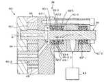
- an illustrative positive displacement pump 24a gear pump, includes gears 46 - 1 , 46 - 2 having meshing teeth 48 from between which coating material is continuously squeezed by their meshing, resulting in delivery of a known amount of coating material for each rotation of the gears 46 - 1 , 46 - 2 regardless of pressure in the coating material circuit 30 and the like.
- the coating materialis delivered through the circuit 30 from a source 32 by, for example, gravity feed, pressurizing the source with a gas or mixture of gases such as compressed air (sometimes referred to herein as “factory air”), etc.
- the thus-delivered coating materialflows from an inlet port 50 , filling the spaces 52 between the teeth 48 of each gear 46 - 1 , 46 - 2 , is carried around the chamber 54 - 1 , 54 - 2 housing each gear 46 - 1 , 46 - 2 , respectively, by the teeth 48 of the gear 46 - 1 , 46 - 2 , and is squeezed from between the teeth 48 of each gear 46 - 1 , 46 - 2 into outlet port 41 as the teeth 48 of gears 46 - 1 , 46 - 2 reengage.
- the cup seals 40 - 1 , 40 - 2 , . . . 40 - nare stacked, one upon the other, thus defining (a) seal chamber(s) 42 - 2 , . . . 42 - n between them.
- the forwardmost seal 40 - 1that is, the one closest to the coating material chamber 54 - 1 , 54 - 2 has a rearward face 64 - 1 which cooperates with the lips 66 - 2 of the next adjacent seal 40 - 2 in the stack to define the seal chamber 42 - 2 .
- At least one 66 - 2 - i , 66 - 3 - i , . . . 66 - n - i of the lips 66 - 2 , 66 - 3 , . . . 66 - n of each of the adjacent seals 40 - 2 , 40 - 3 , . . . 40 - n in the stackis sufficiently flexible that a flushing medium under pressure may be introduced from flushing medium circuit 44 down the shaft 38 past the lips 66 - 2 of the seal 40 - 2 into the passageway 42 - 2 .
- another liquid coating system 120comprises an atomizer 122 of any of the known types and a supply pump 124 .
- the illustrated atomizer 122atomizes and dispenses electrostatically charged coating material particles to coat a target 126 , it should be understood that the atomization and dispensing can either be electrostatically aided or not.
- the coating materialis transported through an intervening fluid circuit 130 from a source 132 of coating material to the dispensing device 122 , for example, by pressurizing the source 132 , by gravity, and by mechanically pumping/metering the coating material in the circuit 130 by a gear pump 124 inserted at a convenient point in the circuit 130 .
- the coating materialis delivered to the atomizer 122 where the coating material is atomized into a cloud, the cloud is shaped and directed toward the target 126 by a flow of compressed gas (for example, air) from a compressed gas source 131 , and/or by electrostatically charging the coating material during atomization from a source 133 of electrostatic potential, and maintaining the target 126 at or near ground potential (as by maintaining a conveyor 137 by which the target 126 is conveyed past the atomizer 122 at or near ground potential and maintaining low electrical resistance between the target 126 and the conveyor 137 .
- compressed gasfor example, air
- pump 124can be driven by a pneumatic or electric motor 136 that requires passage of, for example, a pump drive shaft 138 or operating rod into the fluid path.
- the motor 136may rotate or be a linear motor, such as, for example, a diaphragm-type pump.
- the passage of the pump drive shaft 138 , operating rod or the like into the fluid pathneeds to be sealed 140 to permit the circuit 130 including pump 124 to be pressurized and to permit operation of the pump 124 without leakage of the coating material from the circuit 130 .
- the pressure of the clean flushing medium supplied to pump 124can be controlled from a computer/controller 144 working through compressed gas (typically factory air) pressure regulator 146 controlling a solvent pressure regulator 143 of known type.
- compressed gastypically factory air
- another liquid coating system 220comprises an atomizer 222 of any of the known types.
- a plural component coating materialcomprising components A and B is being dispensed.
- Gear pumps 224 -A and 224 -Binsure delivery of appropriate ratios of the plural components to the atomizer 222 .
- the atomizer 222is illustrated as atomizing and dispensing electrostatically charged coating material particles to coat a target 226 , the atomization and dispensing can either be electrostatically aided or not.
- the A and B components of the coating materialsare transported through intervening fluid circuits 230 -A and 230 -B from respective sources 232 -A and 232 -B of the A and B components to the dispensing device 222 , for example, by pressurizing the sources 232 -A and 232 -B, by gravity, and by mechanically pumping/metering the coating material in the circuits 230 -A and 230 -B by gear pumps 224 -A and 224 -B, inserted at convenient points in the respective circuits 230 -A and 230 -B.
- the pressure of the clean flushing medium supplied to the systems of pumps 224 -A, 224 -Bcan be controlled from computer/controller 244 working through compressed gas (typically factory air) pressure regulators 246 -A, 246 -B controlling solvent pressure regulators 243 -A and 243 -B, respectively, of known type.
- compressed gastypically factory air
Landscapes
- Engineering & Computer Science (AREA)
- Mechanical Engineering (AREA)
- General Engineering & Computer Science (AREA)
- Coating Apparatus (AREA)
- Details And Applications Of Rotary Liquid Pumps (AREA)
- Rotary Pumps (AREA)
Abstract
Description
Claims (10)
Priority Applications (4)
| Application Number | Priority Date | Filing Date | Title |
|---|---|---|---|
| US12/464,378US8225968B2 (en) | 2009-05-12 | 2009-05-12 | Seal system for gear pumps |
| PCT/US2010/029906WO2010132154A2 (en) | 2009-05-12 | 2010-04-05 | Seal system for gear pumps |
| EP10712296AEP2430313A2 (en) | 2009-05-12 | 2010-04-05 | Shaft seal for gear pumps |
| JP2012510809AJP2012526946A (en) | 2009-05-12 | 2010-04-05 | Seal system for gear pump |
Applications Claiming Priority (1)
| Application Number | Priority Date | Filing Date | Title |
|---|---|---|---|
| US12/464,378US8225968B2 (en) | 2009-05-12 | 2009-05-12 | Seal system for gear pumps |
Publications (2)
| Publication Number | Publication Date |
|---|---|
| US20100288793A1 US20100288793A1 (en) | 2010-11-18 |
| US8225968B2true US8225968B2 (en) | 2012-07-24 |
Family
ID=43067694
Family Applications (1)
| Application Number | Title | Priority Date | Filing Date |
|---|---|---|---|
| US12/464,378Active2030-10-22US8225968B2 (en) | 2009-05-12 | 2009-05-12 | Seal system for gear pumps |
Country Status (4)
| Country | Link |
|---|---|
| US (1) | US8225968B2 (en) |
| EP (1) | EP2430313A2 (en) |
| JP (1) | JP2012526946A (en) |
| WO (1) | WO2010132154A2 (en) |
Cited By (2)
| Publication number | Priority date | Publication date | Assignee | Title |
|---|---|---|---|---|
| US20100259015A1 (en)* | 2009-04-08 | 2010-10-14 | Lannie Laroy Dietle | Hydrodynamic seal with improved exclusion and lubrication |
| US20150375249A1 (en)* | 2013-02-18 | 2015-12-31 | Dürr Systems GmbH | Coating agent pump |
Families Citing this family (2)
| Publication number | Priority date | Publication date | Assignee | Title |
|---|---|---|---|---|
| GB201021266D0 (en)* | 2010-12-14 | 2011-01-26 | Crane John Uk Ltd | Seals |
| JP2015010499A (en)* | 2013-06-27 | 2015-01-19 | 旭サナック株式会社 | Gear pump |
Citations (154)
| Publication number | Priority date | Publication date | Assignee | Title |
|---|---|---|---|---|
| US3169882A (en) | 1960-10-05 | 1965-02-16 | Ransburg Electro Coating Corp | Electrostatic coating methods and apparatus |
| US3169883A (en) | 1961-10-25 | 1965-02-16 | Ransburg Electro Coating Corp | Electrostatic coating methods and apparatus |
| FR2260715A1 (en) | 1974-02-12 | 1975-09-05 | Emh | Seals for large diameter bearings - use U-section plastic seals pressed against cylindrical surfaces by springs |
| US3940061A (en) | 1974-09-16 | 1976-02-24 | Champion Spark Plug Company | Electrostatic spray gun for powder coating material |
| US3964683A (en) | 1975-09-02 | 1976-06-22 | Champion Spark Plug Company | Electrostatic spray apparatus |
| US3990609A (en) | 1976-03-12 | 1976-11-09 | Champion Spark Plug Company | Attachment for paint spray gun systems |
| US4002777A (en) | 1967-10-25 | 1977-01-11 | Ransburg Corporation | Method of depositing electrostatically charged liquid coating material |
| US4001935A (en) | 1975-06-12 | 1977-01-11 | Binks Manufacturing Company | Roving cutter |
| US4020393A (en) | 1975-07-16 | 1977-04-26 | Estey Dynamics Corporation | Electrogasdynamic coating device having composite non-conductive flow channel, and hollow ionization electrode for an air jet |
| US4030857A (en) | 1975-10-29 | 1977-06-21 | Champion Spark Plug Company | Paint pump for airless spray guns |
| US4037561A (en) | 1963-06-13 | 1977-07-26 | Ransburg Corporation | Electrostatic coating apparatus |
| US4066041A (en) | 1975-04-11 | 1978-01-03 | Gema Ag Apparatebau | Apparatus for electrostatically applying coating material to articles and the like |
| US4075677A (en) | 1976-08-09 | 1978-02-21 | Ransburg Corporation | Electrostatic coating system |
| US4105164A (en) | 1976-11-26 | 1978-08-08 | Binks Manufacturing Company | Trigger lock mechanism for spray guns |
| US4116364A (en) | 1976-02-02 | 1978-09-26 | Binks Manufacturing Company | Dispensing system for low stability fluids |
| US4133483A (en) | 1977-07-05 | 1979-01-09 | Binks Manufacturing Company | Plural component gun |
| USD252097S (en) | 1978-02-01 | 1979-06-12 | Ransburg Corporation | Spray gun |
| US4165022A (en) | 1977-03-02 | 1979-08-21 | Ransburg Corporation | Hand-held coating-dispensing apparatus |
| US4169545A (en) | 1977-08-01 | 1979-10-02 | Ransburg Corporation | Plural component dispensing apparatus |
| US4171100A (en) | 1976-11-10 | 1979-10-16 | Hajtomuvek Es Festoberendezesek Gyara | Electrostatic paint spraying apparatus |
| US4174070A (en) | 1976-11-08 | 1979-11-13 | Binks Manufacturing Company | Spray gun assembly |
| US4174071A (en) | 1976-11-08 | 1979-11-13 | Binks Manufacturing Company | Spray gun assembly |
| US4187527A (en) | 1976-08-09 | 1980-02-05 | Ransburg Corporation | Electrostatic coating system |
| US4214709A (en) | 1979-03-08 | 1980-07-29 | Binks Manufacturing Company | Electrostatic spray coating apparatus |
| US4248386A (en) | 1977-10-31 | 1981-02-03 | Ransburg Corporation | Electrostatic deposition apparatus |
| US4266721A (en) | 1979-09-17 | 1981-05-12 | Ppg Industries, Inc. | Spray application of coating compositions utilizing induction and corona charging means |
| US4285446A (en) | 1979-06-22 | 1981-08-25 | Ransburg Corporation | Automatic purging system having a pressure sensor and a timing mechanism |
| US4289278A (en) | 1978-09-01 | 1981-09-15 | Onoda Cement Co., Ltd. | Powder electro-charging device and electrostatic powder painting device |
| US4324812A (en) | 1980-05-29 | 1982-04-13 | Ransburg Corporation | Method for controlling the flow of coating material |
| US4331298A (en) | 1977-03-02 | 1982-05-25 | Ransburg Corporation | Hand-held coating-dispensing apparatus |
| USRE30968E (en) | 1976-03-12 | 1982-06-15 | Champion Spark Plug Company | Attachment for paint spray gun systems |
| US4361283A (en) | 1980-09-15 | 1982-11-30 | Binks Manufacturing Company | Plural component spray gun convertible from air atomizing to airless |
| USD270179S (en) | 1981-06-01 | 1983-08-16 | Champion Spark Plug Company | Spray gun |
| USD270180S (en) | 1981-06-01 | 1983-08-16 | Champion Spark Plug Company | Spray gun |
| US4400147A (en) | 1981-03-25 | 1983-08-23 | Binks Manufacturing Company | Flushable rotary gear pump |
| USD270368S (en) | 1981-06-01 | 1983-08-30 | Champion Spark Plug Company | Spray gun |
| USD270367S (en) | 1981-06-01 | 1983-08-30 | Champion Spark Plug Company | Spray gun |
| US4401268A (en) | 1981-09-02 | 1983-08-30 | Binks Manufacturing Company | Spray gun with paint agitator |
| US4433812A (en) | 1980-11-12 | 1984-02-28 | Champion Spark Plug Company | Paint spray attachment |
| US4437614A (en) | 1982-09-28 | 1984-03-20 | Binks Manufacturing Company | Electrostatic air atomization spray coating system |
| US4453670A (en) | 1982-09-13 | 1984-06-12 | Binks Manufacturing Company | Plural component flushless spray gun |
| US4481557A (en) | 1982-09-27 | 1984-11-06 | Ransburg Corporation | Electrostatic coating system |
| US4483483A (en) | 1980-11-12 | 1984-11-20 | Champion Spark Plug Company | Gun for supplying compressed fluid |
| US4485427A (en) | 1982-04-19 | 1984-11-27 | Ransburg Corporation | Fold-back power supply |
| US4513913A (en) | 1982-11-10 | 1985-04-30 | Binks Manufacturing Company | Reversible airless spray nozzle |
| US4515512A (en) | 1980-09-12 | 1985-05-07 | Barmag Barmer Maschinenfabrik Ag | Seal for high pressure pump or the like |
| US4529131A (en) | 1982-11-24 | 1985-07-16 | Ransburg-Gema Ag | Spray device for electrostatic coating of articles with coating material |
| US4534717A (en) | 1981-05-01 | 1985-08-13 | Ford Motor Company | Flushable metering pump |
| US4537357A (en) | 1982-05-03 | 1985-08-27 | Binks Manufacturing Company | Spray guns |
| US4572438A (en) | 1984-05-14 | 1986-02-25 | Nordson Corporation | Airless spray gun having improved nozzle assembly and electrode circuit connections |
| US4606501A (en) | 1983-09-09 | 1986-08-19 | The Devilbiss Company Limited | Miniature spray guns |
| US4613082A (en) | 1984-07-06 | 1986-09-23 | Champion Spark Plug Company | Electrostatic spraying apparatus for robot mounting |
| USD287266S (en) | 1984-04-30 | 1986-12-16 | Binks Manufacturing Company | Nozzle body and a housing for a hand spray gun |
| US4702420A (en) | 1985-02-01 | 1987-10-27 | Ransburg-Gema Ag | Spray gun for coating material |
| US4745520A (en) | 1986-10-10 | 1988-05-17 | Ransburg Corporation | Power supply |
| US4747546A (en) | 1985-08-20 | 1988-05-31 | Ransburg-Gema Ag | Spray apparatus for electrostatic powder coating |
| US4759502A (en) | 1987-07-13 | 1988-07-26 | Binks Manufacturing Company | Spray gun with reversible air/fluid timing |
| US4760962A (en) | 1987-10-30 | 1988-08-02 | The Devilbiss Company | Spray gun paint cup and lid assembly |
| US4770117A (en) | 1987-03-04 | 1988-09-13 | Binks Manufacturing Company | Fiberglass reinforce product spray gun with roving cutter steering mechanism |
| US4819879A (en) | 1985-10-25 | 1989-04-11 | Nordson Corporation | Particle spray gun |
| US4844342A (en) | 1987-09-28 | 1989-07-04 | The Devilbiss Company | Spray gun control circuit |
| USD303139S (en) | 1986-08-25 | 1989-08-29 | DeVilbiss Corporation | Power washer gun |
| USD305057S (en) | 1987-10-30 | 1989-12-12 | The Devilbiss Company | Spray gun |
| USD305453S (en) | 1987-10-30 | 1990-01-09 | The Devilbiss Company | Spray gun |
| USD305452S (en) | 1987-10-30 | 1990-01-09 | The Devilbiss Company | Spray gun unit |
| US4911367A (en) | 1989-03-29 | 1990-03-27 | The Devilbiss Company | Electrostatic spray gun |
| US4921172A (en) | 1987-02-12 | 1990-05-01 | Sames S.A. | Electrostatic sprayer device for spraying products in powder form |
| US4927079A (en) | 1988-10-04 | 1990-05-22 | Binks Manufacturing Company | Plural component air spray gun and method |
| US4934603A (en) | 1989-03-29 | 1990-06-19 | The Devilbiss Company | Hand held electrostatic spray gun |
| US4934607A (en) | 1989-03-29 | 1990-06-19 | The Devilbiss Company | Hand held electrostatic spray gun with internal power supply |
| EP0412634A2 (en) | 1989-08-10 | 1991-02-13 | Mitsubishi Denki Kabushiki Kaisha | Sealing device for oil rotary vacuum pump |
| US4993645A (en) | 1989-02-14 | 1991-02-19 | Ransburg-Gema Ag | Spray coating device for electrostatic spray coating |
| US5022590A (en) | 1989-02-14 | 1991-06-11 | Ransburg-Gema Ag | Spray gun for electrostatic spray coating |
| USD318712S (en) | 1988-07-04 | 1991-07-30 | Ransburg-Gema Ag | Spray gun for coating articles |
| US5039019A (en) | 1990-08-01 | 1991-08-13 | Illinois Tool Works, Inc. | Indirect charging electrostatic coating apparatus |
| US5054687A (en) | 1990-03-14 | 1991-10-08 | Ransburg Corporation | Pressure feed paint cup |
| US5064119A (en) | 1989-02-03 | 1991-11-12 | Binks Manufacturing Company | High-volume low pressure air spray gun |
| US5074466A (en) | 1990-01-16 | 1991-12-24 | Binks Manufacturing Company | Fluid valve stem for air spray gun |
| US5090623A (en) | 1990-12-06 | 1992-02-25 | Ransburg Corporation | Paint spray gun |
| US5118080A (en) | 1989-07-15 | 1992-06-02 | Suttner Gmbh & Co. Kg | Valve pistol for a high pressure cleaning apparatus |
| US5119992A (en) | 1991-02-11 | 1992-06-09 | Ransburg Corporation | Spray gun with regulated pressure feed paint cup |
| US5159244A (en) | 1991-07-17 | 1992-10-27 | Poulson Daniel A | Ignition circuit for gas discharge lamp |
| US5178330A (en) | 1991-05-17 | 1993-01-12 | Ransburg Corporation | Electrostatic high voltage, low pressure paint spray gun |
| US5180297A (en) | 1991-03-22 | 1993-01-19 | The Gorman-Rupp Company | Fluid transfer pump with shaft seal structure |
| US5180104A (en) | 1991-02-20 | 1993-01-19 | Binks Manufacturing Company | Hydraulically assisted high volume low pressure air spray gun |
| US5209405A (en) | 1991-04-19 | 1993-05-11 | Ransburg Corporation | Baffle for hvlp paint spray gun |
| US5209365A (en) | 1992-09-01 | 1993-05-11 | Devilbiss Air Power Company | Paint cup lid assembly |
| US5228842A (en)* | 1991-07-30 | 1993-07-20 | Wagner Spray Tech Corporation | Quick-change fluid section for piston-type paint pumps |
| US5236129A (en) | 1992-05-27 | 1993-08-17 | Ransburg Corporation | Ergonomic hand held paint spray gun |
| US5284299A (en) | 1991-03-11 | 1994-02-08 | Ransburg Corporation | Pressure compensated HVLP spray gun |
| US5284301A (en) | 1992-12-15 | 1994-02-08 | Wagner Spray Tech Corporation | Double-pivot trigger |
| US5299740A (en) | 1992-03-17 | 1994-04-05 | Binks Manufacturing Company | Plural component airless spray gun with mechanical purge |
| US5303865A (en) | 1990-07-26 | 1994-04-19 | Binks Manufacturing Company | Plural component external mix spray gun and method |
| US5332156A (en) | 1993-10-25 | 1994-07-26 | Ransburg Corporation | Spray gun with removable cover and method for securing a cover to a spray gun |
| USD349559S (en) | 1993-10-18 | 1994-08-09 | Ransburg Corporation | Spray gun handle cover |
| US5351887A (en) | 1993-02-16 | 1994-10-04 | Binks Manufacturing Company | Pumping and spraying system for heavy materials |
| US5395054A (en) | 1994-03-21 | 1995-03-07 | Ransburg Corporation | Fluid and air hose system for hand held paint spray gun |
| US5400971A (en) | 1993-12-20 | 1995-03-28 | Binks Manufacturing Company | Side injected plural component spray gun |
| DE19515094A1 (en) | 1994-05-04 | 1995-11-09 | Friatec Rheinhuette Gmbh & Co | Shaft sealing for chemical pump |
| US5553788A (en) | 1993-10-15 | 1996-09-10 | Binks Manufacturing Company | Spray gun assembly and system for fluent materials |
| US5582350A (en) | 1994-04-19 | 1996-12-10 | Ransburg Corporation | Hand held paint spray gun with top mounted paint cup |
| US5618001A (en) | 1995-03-20 | 1997-04-08 | Binks Manufacturing Company | Spray gun for aggregates |
| US5632816A (en) | 1994-07-12 | 1997-05-27 | Ransburg Corporation | Voltage block |
| US5639027A (en) | 1994-12-08 | 1997-06-17 | Ransburg Corporation | Two component external mix spray gun |
| US5704977A (en) | 1993-03-04 | 1998-01-06 | Behr Systems, Inc. | Coating arrangement with a rotary atomizer |
| EP0643223B1 (en) | 1993-07-17 | 1998-02-04 | Maag Pump Systems Textron AG | Method and arrangement for sealing a shaft passage in gear pumps |
| USRE35769E (en) | 1992-05-27 | 1998-04-14 | Ransburg Corporation | Spray gun having trigger overtravel protection and maximum flow adjustment knob warning |
| US5803313A (en) | 1996-05-21 | 1998-09-08 | Illinois Tool Works Inc. | Hand held fluid dispensing apparatus |
| US5829679A (en) | 1996-08-20 | 1998-11-03 | Binks Sames Corporation | Plural component airless spray gun with mechanical purge |
| US5836517A (en) | 1995-01-03 | 1998-11-17 | Ransburg Corporation | Spray gun with fluid valve |
| US5978244A (en) | 1997-10-16 | 1999-11-02 | Illinois Tool Works, Inc. | Programmable logic control system for a HVDC power supply |
| US6144570A (en) | 1997-10-16 | 2000-11-07 | Illinois Tool Works Inc. | Control system for a HVDC power supply |
| US6179223B1 (en) | 1999-08-16 | 2001-01-30 | Illinois Tool Works | Spray nozzle fluid regulator and restrictor combination |
| US6183231B1 (en) | 1997-01-31 | 2001-02-06 | United Dominion Industries, Inc. | Clean-in-place gear pump |
| US6189809B1 (en) | 1999-09-23 | 2001-02-20 | Illinois Tool Works Inc. | Multi-feed spray gun |
| US6276616B1 (en) | 2000-04-07 | 2001-08-21 | Illinois Tool Works Inc. | Fluid needle loading assembly for an airless spray paint gun |
| WO2001085353A1 (en) | 2000-05-10 | 2001-11-15 | Paolo Checcucci | Plant for electrostatic painting with a venturi nozzle |
| US6402058B2 (en) | 2000-03-15 | 2002-06-11 | Ransburg Industrial Finishing K.K. | Aerosol spray gun |
| US6460787B1 (en) | 1998-10-22 | 2002-10-08 | Nordson Corporation | Modular fluid spray gun |
| US20020170580A1 (en)* | 2001-05-16 | 2002-11-21 | Clifford Scott J. | Method and apparatus for cleaning a bell atomizer spray head |
| US6572029B1 (en) | 1993-12-02 | 2003-06-03 | Illinois Tool Works Inc. | Recirculating paint system having an improved push to connect fluid coupling assembly |
| US6585481B1 (en) | 1998-07-16 | 2003-07-01 | Abb Flexible Automation As | Paint pumping device |
| US6669112B2 (en) | 2001-04-11 | 2003-12-30 | Illinois Tool Works, Inc. | Air assisted spray system with an improved air cap |
| US20040007821A1 (en)* | 2000-04-13 | 2004-01-15 | Ramsay Thomas W. | Sealing apparatus having sequentially engageble seals |
| US6679193B2 (en) | 1993-05-25 | 2004-01-20 | Nordson Corporation | Vehicle powder coating system |
| US6698670B1 (en) | 2003-06-10 | 2004-03-02 | Illinois Tool Works Inc. | Friction fit paint cup connection |
| US6706641B2 (en) | 2001-09-13 | 2004-03-16 | Micell Technologies, Inc. | Spray member and method for using the same |
| US6712292B1 (en) | 2003-06-10 | 2004-03-30 | Illinois Tool Works Inc. | Adjustable adapter for gravity-feed paint sprayer |
| US6726065B2 (en) | 2002-02-04 | 2004-04-27 | Brian C. Sanders | Modular automatic colorant dispenser |
| USRE38526E1 (en) | 1997-07-11 | 2004-06-08 | Nordson Corporation | Electrostatic rotary atomizing spray device with improved atomizer cup |
| US6758425B2 (en) | 2001-03-09 | 2004-07-06 | Itw Gema Ag | Coating-powder spray gun |
| US6776362B2 (en) | 2000-06-29 | 2004-08-17 | Anest Iwata Corporation | Electrostatic painting device |
| US6790285B2 (en) | 2000-07-21 | 2004-09-14 | Anest Iwata Corporation | Electrostatic coater with power transmission frequency adjuster |
| US6796519B1 (en) | 1999-09-16 | 2004-09-28 | Nordson Corporation | Powder spray gun |
| US6817553B2 (en) | 2003-02-04 | 2004-11-16 | Efc Systems, Inc. | Powder paint spray coating apparatus having selectable, modular spray applicators |
| US6854672B2 (en) | 2002-07-11 | 2005-02-15 | Illinois Tool Works Inc. | Air-assisted air valve for air atomized spray guns |
| WO2005014177A1 (en) | 2003-08-12 | 2005-02-17 | The University Of Western Ontario | Method and apparatus for dispensing paint powders for powder coatings |
| US20050087068A1 (en) | 2003-10-23 | 2005-04-28 | Smc Kabushiki Kaisha | Lubricating structure for hydraulic driving apparatus |
| US20050093246A1 (en)* | 2003-11-05 | 2005-05-05 | Dietle Lannie L. | Rotary shaft sealing assembly |
| US6916023B2 (en) | 2002-08-30 | 2005-07-12 | Illinois Tool Works Inc. | Self-adjusting cartridge seal |
| US6929698B2 (en) | 1993-05-25 | 2005-08-16 | Nordson Corporation | Vehicle powder coating system |
| US6951309B2 (en) | 2001-08-08 | 2005-10-04 | Itw Gema Ag | Powder spray coating device |
| US6955724B2 (en) | 2002-10-29 | 2005-10-18 | Itw Oberflachentechnik Gmbh & Co. Kg | Spray-coating device for a coating liquid |
| US20050253340A1 (en)* | 2000-04-13 | 2005-11-17 | Ashbridge & Roseburgh Inc. | Sealing apparatus having sequentially engageable seals |
| US20060081729A1 (en) | 2004-10-14 | 2006-04-20 | Kimiyoshi Nagai | Electrostatic spraying apparatus |
| US7128277B2 (en) | 2003-07-29 | 2006-10-31 | Illinois Tool Works Inc. | Powder bell with secondary charging electrode |
| US7143963B2 (en) | 2003-09-10 | 2006-12-05 | Toyota Jidosha Kabushiki Kaisha | Rotary atomizer and coating method by it |
| US20060283386A1 (en) | 2005-06-16 | 2006-12-21 | Alexander Kevin L | In-gun power supply control |
| US7217442B2 (en) | 2001-12-20 | 2007-05-15 | Ppg Industries, Ohio, Inc. | Method and apparatus for mixing and applying a multi-component coating composition |
| US20070205561A1 (en) | 2004-07-22 | 2007-09-06 | Kayaba Industry Co., Ltd. | Sealing Structure for Sliding Part |
| US7292322B2 (en) | 2003-12-29 | 2007-11-06 | At&T Corp. | Method for increasing accuracy of measurement of mean polarization mode dispersion |
| US7296759B2 (en) | 2004-11-19 | 2007-11-20 | Illinois Tool Works Inc. | Ratcheting retaining ring |
| US7296760B2 (en) | 2004-11-17 | 2007-11-20 | Illinois Tool Works Inc. | Indexing valve |
| WO2008135326A1 (en) | 2007-05-03 | 2008-11-13 | Oerlikon Textile Gmbh & Co. Kg | Gear pump |
Family Cites Families (3)
| Publication number | Priority date | Publication date | Assignee | Title |
|---|---|---|---|---|
| US4553670A (en)* | 1981-10-30 | 1985-11-19 | Richard Collens | Medical reminder device |
| US4828218A (en) | 1987-12-02 | 1989-05-09 | Ransburg Corporation | Multiple mode regulator |
| CA1316980C (en) | 1988-12-27 | 1993-04-27 | Daniel C. Hughey | Power supply |
- 2009
- 2009-05-12USUS12/464,378patent/US8225968B2/enactiveActive
- 2010
- 2010-04-05JPJP2012510809Apatent/JP2012526946A/enactivePending
- 2010-04-05WOPCT/US2010/029906patent/WO2010132154A2/enactiveApplication Filing
- 2010-04-05EPEP10712296Apatent/EP2430313A2/ennot_activeWithdrawn
Patent Citations (171)
| Publication number | Priority date | Publication date | Assignee | Title |
|---|---|---|---|---|
| US3169882A (en) | 1960-10-05 | 1965-02-16 | Ransburg Electro Coating Corp | Electrostatic coating methods and apparatus |
| US3169883A (en) | 1961-10-25 | 1965-02-16 | Ransburg Electro Coating Corp | Electrostatic coating methods and apparatus |
| US4114564A (en) | 1963-06-13 | 1978-09-19 | Ransburg Corporation | Electrostatic coating apparatus |
| US4037561A (en) | 1963-06-13 | 1977-07-26 | Ransburg Corporation | Electrostatic coating apparatus |
| US4002777A (en) | 1967-10-25 | 1977-01-11 | Ransburg Corporation | Method of depositing electrostatically charged liquid coating material |
| FR2260715A1 (en) | 1974-02-12 | 1975-09-05 | Emh | Seals for large diameter bearings - use U-section plastic seals pressed against cylindrical surfaces by springs |
| US3940061A (en) | 1974-09-16 | 1976-02-24 | Champion Spark Plug Company | Electrostatic spray gun for powder coating material |
| US4066041A (en) | 1975-04-11 | 1978-01-03 | Gema Ag Apparatebau | Apparatus for electrostatically applying coating material to articles and the like |
| US4001935A (en) | 1975-06-12 | 1977-01-11 | Binks Manufacturing Company | Roving cutter |
| US4081904A (en) | 1975-06-12 | 1978-04-04 | Binks Manufacturing Company | Roving cutter |
| US4020393A (en) | 1975-07-16 | 1977-04-26 | Estey Dynamics Corporation | Electrogasdynamic coating device having composite non-conductive flow channel, and hollow ionization electrode for an air jet |
| US3964683A (en) | 1975-09-02 | 1976-06-22 | Champion Spark Plug Company | Electrostatic spray apparatus |
| US4030857A (en) | 1975-10-29 | 1977-06-21 | Champion Spark Plug Company | Paint pump for airless spray guns |
| US4116364A (en) | 1976-02-02 | 1978-09-26 | Binks Manufacturing Company | Dispensing system for low stability fluids |
| US3990609A (en) | 1976-03-12 | 1976-11-09 | Champion Spark Plug Company | Attachment for paint spray gun systems |
| USRE30968E (en) | 1976-03-12 | 1982-06-15 | Champion Spark Plug Company | Attachment for paint spray gun systems |
| US4075677A (en) | 1976-08-09 | 1978-02-21 | Ransburg Corporation | Electrostatic coating system |
| US4187527A (en) | 1976-08-09 | 1980-02-05 | Ransburg Corporation | Electrostatic coating system |
| US4174070A (en) | 1976-11-08 | 1979-11-13 | Binks Manufacturing Company | Spray gun assembly |
| US4174071A (en) | 1976-11-08 | 1979-11-13 | Binks Manufacturing Company | Spray gun assembly |
| US4171100A (en) | 1976-11-10 | 1979-10-16 | Hajtomuvek Es Festoberendezesek Gyara | Electrostatic paint spraying apparatus |
| US4105164A (en) | 1976-11-26 | 1978-08-08 | Binks Manufacturing Company | Trigger lock mechanism for spray guns |
| US4165022A (en) | 1977-03-02 | 1979-08-21 | Ransburg Corporation | Hand-held coating-dispensing apparatus |
| US4331298A (en) | 1977-03-02 | 1982-05-25 | Ransburg Corporation | Hand-held coating-dispensing apparatus |
| US4133483A (en) | 1977-07-05 | 1979-01-09 | Binks Manufacturing Company | Plural component gun |
| US4169545A (en) | 1977-08-01 | 1979-10-02 | Ransburg Corporation | Plural component dispensing apparatus |
| US4248386A (en) | 1977-10-31 | 1981-02-03 | Ransburg Corporation | Electrostatic deposition apparatus |
| USD252097S (en) | 1978-02-01 | 1979-06-12 | Ransburg Corporation | Spray gun |
| US4289278A (en) | 1978-09-01 | 1981-09-15 | Onoda Cement Co., Ltd. | Powder electro-charging device and electrostatic powder painting device |
| US4214709A (en) | 1979-03-08 | 1980-07-29 | Binks Manufacturing Company | Electrostatic spray coating apparatus |
| US4285446A (en) | 1979-06-22 | 1981-08-25 | Ransburg Corporation | Automatic purging system having a pressure sensor and a timing mechanism |
| US4266721A (en) | 1979-09-17 | 1981-05-12 | Ppg Industries, Inc. | Spray application of coating compositions utilizing induction and corona charging means |
| US4324812A (en) | 1980-05-29 | 1982-04-13 | Ransburg Corporation | Method for controlling the flow of coating material |
| US4515512A (en) | 1980-09-12 | 1985-05-07 | Barmag Barmer Maschinenfabrik Ag | Seal for high pressure pump or the like |
| US4361283A (en) | 1980-09-15 | 1982-11-30 | Binks Manufacturing Company | Plural component spray gun convertible from air atomizing to airless |
| US4433812A (en) | 1980-11-12 | 1984-02-28 | Champion Spark Plug Company | Paint spray attachment |
| US4483483A (en) | 1980-11-12 | 1984-11-20 | Champion Spark Plug Company | Gun for supplying compressed fluid |
| US4400147A (en) | 1981-03-25 | 1983-08-23 | Binks Manufacturing Company | Flushable rotary gear pump |
| US4534717A (en) | 1981-05-01 | 1985-08-13 | Ford Motor Company | Flushable metering pump |
| USD270367S (en) | 1981-06-01 | 1983-08-30 | Champion Spark Plug Company | Spray gun |
| USD270368S (en) | 1981-06-01 | 1983-08-30 | Champion Spark Plug Company | Spray gun |
| USD270180S (en) | 1981-06-01 | 1983-08-16 | Champion Spark Plug Company | Spray gun |
| USD270179S (en) | 1981-06-01 | 1983-08-16 | Champion Spark Plug Company | Spray gun |
| US4401268A (en) | 1981-09-02 | 1983-08-30 | Binks Manufacturing Company | Spray gun with paint agitator |
| US4485427A (en) | 1982-04-19 | 1984-11-27 | Ransburg Corporation | Fold-back power supply |
| US4537357A (en) | 1982-05-03 | 1985-08-27 | Binks Manufacturing Company | Spray guns |
| US4453670A (en) | 1982-09-13 | 1984-06-12 | Binks Manufacturing Company | Plural component flushless spray gun |
| US4481557A (en) | 1982-09-27 | 1984-11-06 | Ransburg Corporation | Electrostatic coating system |
| US4437614A (en) | 1982-09-28 | 1984-03-20 | Binks Manufacturing Company | Electrostatic air atomization spray coating system |
| US4513913A (en) | 1982-11-10 | 1985-04-30 | Binks Manufacturing Company | Reversible airless spray nozzle |
| US4529131A (en) | 1982-11-24 | 1985-07-16 | Ransburg-Gema Ag | Spray device for electrostatic coating of articles with coating material |
| US4606501A (en) | 1983-09-09 | 1986-08-19 | The Devilbiss Company Limited | Miniature spray guns |
| USD287266S (en) | 1984-04-30 | 1986-12-16 | Binks Manufacturing Company | Nozzle body and a housing for a hand spray gun |
| US4572438A (en) | 1984-05-14 | 1986-02-25 | Nordson Corporation | Airless spray gun having improved nozzle assembly and electrode circuit connections |
| US4613082A (en) | 1984-07-06 | 1986-09-23 | Champion Spark Plug Company | Electrostatic spraying apparatus for robot mounting |
| US4702420A (en) | 1985-02-01 | 1987-10-27 | Ransburg-Gema Ag | Spray gun for coating material |
| US4747546A (en) | 1985-08-20 | 1988-05-31 | Ransburg-Gema Ag | Spray apparatus for electrostatic powder coating |
| US4819879A (en) | 1985-10-25 | 1989-04-11 | Nordson Corporation | Particle spray gun |
| USD303139S (en) | 1986-08-25 | 1989-08-29 | DeVilbiss Corporation | Power washer gun |
| US4745520A (en) | 1986-10-10 | 1988-05-17 | Ransburg Corporation | Power supply |
| US4921172A (en) | 1987-02-12 | 1990-05-01 | Sames S.A. | Electrostatic sprayer device for spraying products in powder form |
| US4770117A (en) | 1987-03-04 | 1988-09-13 | Binks Manufacturing Company | Fiberglass reinforce product spray gun with roving cutter steering mechanism |
| US4759502A (en) | 1987-07-13 | 1988-07-26 | Binks Manufacturing Company | Spray gun with reversible air/fluid timing |
| US4844342A (en) | 1987-09-28 | 1989-07-04 | The Devilbiss Company | Spray gun control circuit |
| USD305057S (en) | 1987-10-30 | 1989-12-12 | The Devilbiss Company | Spray gun |
| USD305453S (en) | 1987-10-30 | 1990-01-09 | The Devilbiss Company | Spray gun |
| USD305452S (en) | 1987-10-30 | 1990-01-09 | The Devilbiss Company | Spray gun unit |
| US4760962A (en) | 1987-10-30 | 1988-08-02 | The Devilbiss Company | Spray gun paint cup and lid assembly |
| USD318712S (en) | 1988-07-04 | 1991-07-30 | Ransburg-Gema Ag | Spray gun for coating articles |
| USD325241S (en) | 1988-07-04 | 1992-04-07 | Ransburg-Gema Ag | Spray gun for coating articles |
| US4927079A (en) | 1988-10-04 | 1990-05-22 | Binks Manufacturing Company | Plural component air spray gun and method |
| US5064119A (en) | 1989-02-03 | 1991-11-12 | Binks Manufacturing Company | High-volume low pressure air spray gun |
| USRE36378E (en) | 1989-02-03 | 1999-11-09 | Binks Manufacturing Company | High volume low pressure air spray gun |
| US4993645A (en) | 1989-02-14 | 1991-02-19 | Ransburg-Gema Ag | Spray coating device for electrostatic spray coating |
| US5022590A (en) | 1989-02-14 | 1991-06-11 | Ransburg-Gema Ag | Spray gun for electrostatic spray coating |
| US4934607A (en) | 1989-03-29 | 1990-06-19 | The Devilbiss Company | Hand held electrostatic spray gun with internal power supply |
| US4911367A (en) | 1989-03-29 | 1990-03-27 | The Devilbiss Company | Electrostatic spray gun |
| US4934603A (en) | 1989-03-29 | 1990-06-19 | The Devilbiss Company | Hand held electrostatic spray gun |
| US5118080A (en) | 1989-07-15 | 1992-06-02 | Suttner Gmbh & Co. Kg | Valve pistol for a high pressure cleaning apparatus |
| EP0412634A2 (en) | 1989-08-10 | 1991-02-13 | Mitsubishi Denki Kabushiki Kaisha | Sealing device for oil rotary vacuum pump |
| US5074466A (en) | 1990-01-16 | 1991-12-24 | Binks Manufacturing Company | Fluid valve stem for air spray gun |
| US5054687A (en) | 1990-03-14 | 1991-10-08 | Ransburg Corporation | Pressure feed paint cup |
| US5303865A (en) | 1990-07-26 | 1994-04-19 | Binks Manufacturing Company | Plural component external mix spray gun and method |
| US5039019A (en) | 1990-08-01 | 1991-08-13 | Illinois Tool Works, Inc. | Indirect charging electrostatic coating apparatus |
| US5090623A (en) | 1990-12-06 | 1992-02-25 | Ransburg Corporation | Paint spray gun |
| US5119992A (en) | 1991-02-11 | 1992-06-09 | Ransburg Corporation | Spray gun with regulated pressure feed paint cup |
| US5180104A (en) | 1991-02-20 | 1993-01-19 | Binks Manufacturing Company | Hydraulically assisted high volume low pressure air spray gun |
| US5284299A (en) | 1991-03-11 | 1994-02-08 | Ransburg Corporation | Pressure compensated HVLP spray gun |
| US5180297A (en) | 1991-03-22 | 1993-01-19 | The Gorman-Rupp Company | Fluid transfer pump with shaft seal structure |
| US5209405A (en) | 1991-04-19 | 1993-05-11 | Ransburg Corporation | Baffle for hvlp paint spray gun |
| US5178330A (en) | 1991-05-17 | 1993-01-12 | Ransburg Corporation | Electrostatic high voltage, low pressure paint spray gun |
| US5159244A (en) | 1991-07-17 | 1992-10-27 | Poulson Daniel A | Ignition circuit for gas discharge lamp |
| US5228842A (en)* | 1991-07-30 | 1993-07-20 | Wagner Spray Tech Corporation | Quick-change fluid section for piston-type paint pumps |
| US5299740A (en) | 1992-03-17 | 1994-04-05 | Binks Manufacturing Company | Plural component airless spray gun with mechanical purge |
| US5236129A (en) | 1992-05-27 | 1993-08-17 | Ransburg Corporation | Ergonomic hand held paint spray gun |
| US5289974A (en) | 1992-05-27 | 1994-03-01 | Ransburg Corporation | Spray gun having trigger overtravel protection and maximum flow adjustment knob warning |
| US5330108A (en) | 1992-05-27 | 1994-07-19 | Ransburg Corporation | Spray gun having both mechanical and pneumatic valve actuation |
| US5332159A (en) | 1992-05-27 | 1994-07-26 | Ransburg Corporation | Spray gun with dual mode trigger |
| USRE35769E (en) | 1992-05-27 | 1998-04-14 | Ransburg Corporation | Spray gun having trigger overtravel protection and maximum flow adjustment knob warning |
| US5209365A (en) | 1992-09-01 | 1993-05-11 | Devilbiss Air Power Company | Paint cup lid assembly |
| US5284301A (en) | 1992-12-15 | 1994-02-08 | Wagner Spray Tech Corporation | Double-pivot trigger |
| US5351887A (en) | 1993-02-16 | 1994-10-04 | Binks Manufacturing Company | Pumping and spraying system for heavy materials |
| US5704977A (en) | 1993-03-04 | 1998-01-06 | Behr Systems, Inc. | Coating arrangement with a rotary atomizer |
| US6679193B2 (en) | 1993-05-25 | 2004-01-20 | Nordson Corporation | Vehicle powder coating system |
| US6929698B2 (en) | 1993-05-25 | 2005-08-16 | Nordson Corporation | Vehicle powder coating system |
| US7166164B2 (en) | 1993-05-25 | 2007-01-23 | Nordson Corporation | Vehicle powder coating system |
| US7247205B2 (en) | 1993-05-25 | 2007-07-24 | Nordson Corporation | Vehicle powder coating system |
| EP0643223B1 (en) | 1993-07-17 | 1998-02-04 | Maag Pump Systems Textron AG | Method and arrangement for sealing a shaft passage in gear pumps |
| US5553788A (en) | 1993-10-15 | 1996-09-10 | Binks Manufacturing Company | Spray gun assembly and system for fluent materials |
| USD349559S (en) | 1993-10-18 | 1994-08-09 | Ransburg Corporation | Spray gun handle cover |
| US5332156A (en) | 1993-10-25 | 1994-07-26 | Ransburg Corporation | Spray gun with removable cover and method for securing a cover to a spray gun |
| US6572029B1 (en) | 1993-12-02 | 2003-06-03 | Illinois Tool Works Inc. | Recirculating paint system having an improved push to connect fluid coupling assembly |
| US5400971A (en) | 1993-12-20 | 1995-03-28 | Binks Manufacturing Company | Side injected plural component spray gun |
| US5395054A (en) | 1994-03-21 | 1995-03-07 | Ransburg Corporation | Fluid and air hose system for hand held paint spray gun |
| US5582350A (en) | 1994-04-19 | 1996-12-10 | Ransburg Corporation | Hand held paint spray gun with top mounted paint cup |
| DE19515094A1 (en) | 1994-05-04 | 1995-11-09 | Friatec Rheinhuette Gmbh & Co | Shaft sealing for chemical pump |
| US5787928A (en) | 1994-07-12 | 1998-08-04 | Ransburg Corporation | Valve structure |
| US5746831A (en) | 1994-07-12 | 1998-05-05 | Ransburg Corporation | Voltage block |
| US5944045A (en) | 1994-07-12 | 1999-08-31 | Ransburg Corporation | Solvent circuit |
| US5632816A (en) | 1994-07-12 | 1997-05-27 | Ransburg Corporation | Voltage block |
| US5639027A (en) | 1994-12-08 | 1997-06-17 | Ransburg Corporation | Two component external mix spray gun |
| US5836517A (en) | 1995-01-03 | 1998-11-17 | Ransburg Corporation | Spray gun with fluid valve |
| US5618001A (en) | 1995-03-20 | 1997-04-08 | Binks Manufacturing Company | Spray gun for aggregates |
| US5803313A (en) | 1996-05-21 | 1998-09-08 | Illinois Tool Works Inc. | Hand held fluid dispensing apparatus |
| US5829679A (en) | 1996-08-20 | 1998-11-03 | Binks Sames Corporation | Plural component airless spray gun with mechanical purge |
| US6183231B1 (en) | 1997-01-31 | 2001-02-06 | United Dominion Industries, Inc. | Clean-in-place gear pump |
| USRE38526E1 (en) | 1997-07-11 | 2004-06-08 | Nordson Corporation | Electrostatic rotary atomizing spray device with improved atomizer cup |
| US6562137B2 (en) | 1997-10-16 | 2003-05-13 | Illinois Tool Works Inc | Power supply control system |
| US6423142B1 (en) | 1997-10-16 | 2002-07-23 | Illinois Tool Works Inc. | Power supply control system |
| US6144570A (en) | 1997-10-16 | 2000-11-07 | Illinois Tool Works Inc. | Control system for a HVDC power supply |
| US5978244A (en) | 1997-10-16 | 1999-11-02 | Illinois Tool Works, Inc. | Programmable logic control system for a HVDC power supply |
| US6585481B1 (en) | 1998-07-16 | 2003-07-01 | Abb Flexible Automation As | Paint pumping device |
| US20030006322A1 (en) | 1998-10-22 | 2003-01-09 | Hartle Ronald J. | Modular fluid spray gun |
| US6460787B1 (en) | 1998-10-22 | 2002-10-08 | Nordson Corporation | Modular fluid spray gun |
| US6877681B2 (en) | 1998-10-22 | 2005-04-12 | Nordson Corporation | Spray gun having improved fluid tip with conductive path |
| US6179223B1 (en) | 1999-08-16 | 2001-01-30 | Illinois Tool Works | Spray nozzle fluid regulator and restrictor combination |
| US6796519B1 (en) | 1999-09-16 | 2004-09-28 | Nordson Corporation | Powder spray gun |
| US6189809B1 (en) | 1999-09-23 | 2001-02-20 | Illinois Tool Works Inc. | Multi-feed spray gun |
| US6402058B2 (en) | 2000-03-15 | 2002-06-11 | Ransburg Industrial Finishing K.K. | Aerosol spray gun |
| US6276616B1 (en) | 2000-04-07 | 2001-08-21 | Illinois Tool Works Inc. | Fluid needle loading assembly for an airless spray paint gun |
| US20040007821A1 (en)* | 2000-04-13 | 2004-01-15 | Ramsay Thomas W. | Sealing apparatus having sequentially engageble seals |
| US20050253340A1 (en)* | 2000-04-13 | 2005-11-17 | Ashbridge & Roseburgh Inc. | Sealing apparatus having sequentially engageable seals |
| WO2001085353A1 (en) | 2000-05-10 | 2001-11-15 | Paolo Checcucci | Plant for electrostatic painting with a venturi nozzle |
| US6776362B2 (en) | 2000-06-29 | 2004-08-17 | Anest Iwata Corporation | Electrostatic painting device |
| US6790285B2 (en) | 2000-07-21 | 2004-09-14 | Anest Iwata Corporation | Electrostatic coater with power transmission frequency adjuster |
| US6758425B2 (en) | 2001-03-09 | 2004-07-06 | Itw Gema Ag | Coating-powder spray gun |
| US6669112B2 (en) | 2001-04-11 | 2003-12-30 | Illinois Tool Works, Inc. | Air assisted spray system with an improved air cap |
| US20020170580A1 (en)* | 2001-05-16 | 2002-11-21 | Clifford Scott J. | Method and apparatus for cleaning a bell atomizer spray head |
| US6951309B2 (en) | 2001-08-08 | 2005-10-04 | Itw Gema Ag | Powder spray coating device |
| US6730612B2 (en) | 2001-09-13 | 2004-05-04 | Micell Technologies, Inc. | Spray member and method for using the same |
| US6706641B2 (en) | 2001-09-13 | 2004-03-16 | Micell Technologies, Inc. | Spray member and method for using the same |
| US7217442B2 (en) | 2001-12-20 | 2007-05-15 | Ppg Industries, Ohio, Inc. | Method and apparatus for mixing and applying a multi-component coating composition |
| US6726065B2 (en) | 2002-02-04 | 2004-04-27 | Brian C. Sanders | Modular automatic colorant dispenser |
| US6854672B2 (en) | 2002-07-11 | 2005-02-15 | Illinois Tool Works Inc. | Air-assisted air valve for air atomized spray guns |
| US6916023B2 (en) | 2002-08-30 | 2005-07-12 | Illinois Tool Works Inc. | Self-adjusting cartridge seal |
| US6955724B2 (en) | 2002-10-29 | 2005-10-18 | Itw Oberflachentechnik Gmbh & Co. Kg | Spray-coating device for a coating liquid |
| US6817553B2 (en) | 2003-02-04 | 2004-11-16 | Efc Systems, Inc. | Powder paint spray coating apparatus having selectable, modular spray applicators |
| US6698670B1 (en) | 2003-06-10 | 2004-03-02 | Illinois Tool Works Inc. | Friction fit paint cup connection |
| US6712292B1 (en) | 2003-06-10 | 2004-03-30 | Illinois Tool Works Inc. | Adjustable adapter for gravity-feed paint sprayer |
| US7128277B2 (en) | 2003-07-29 | 2006-10-31 | Illinois Tool Works Inc. | Powder bell with secondary charging electrode |
| WO2005014177A1 (en) | 2003-08-12 | 2005-02-17 | The University Of Western Ontario | Method and apparatus for dispensing paint powders for powder coatings |
| US7143963B2 (en) | 2003-09-10 | 2006-12-05 | Toyota Jidosha Kabushiki Kaisha | Rotary atomizer and coating method by it |
| US20050087068A1 (en) | 2003-10-23 | 2005-04-28 | Smc Kabushiki Kaisha | Lubricating structure for hydraulic driving apparatus |
| US20050093246A1 (en)* | 2003-11-05 | 2005-05-05 | Dietle Lannie L. | Rotary shaft sealing assembly |
| US7292322B2 (en) | 2003-12-29 | 2007-11-06 | At&T Corp. | Method for increasing accuracy of measurement of mean polarization mode dispersion |
| US20070205561A1 (en) | 2004-07-22 | 2007-09-06 | Kayaba Industry Co., Ltd. | Sealing Structure for Sliding Part |
| US20060081729A1 (en) | 2004-10-14 | 2006-04-20 | Kimiyoshi Nagai | Electrostatic spraying apparatus |
| US7296760B2 (en) | 2004-11-17 | 2007-11-20 | Illinois Tool Works Inc. | Indexing valve |
| US7296759B2 (en) | 2004-11-19 | 2007-11-20 | Illinois Tool Works Inc. | Ratcheting retaining ring |
| US20060283386A1 (en) | 2005-06-16 | 2006-12-21 | Alexander Kevin L | In-gun power supply control |
| WO2008135326A1 (en) | 2007-05-03 | 2008-11-13 | Oerlikon Textile Gmbh & Co. Kg | Gear pump |
Non-Patent Citations (6)
| Title |
|---|
| "Automatic R-E-A III Electrostatic Spray or R-E-A III-L Electrostatic HVLP Spray", ITW Ransburg Electrostatic Systems, 1996, 2 pages. |
| "M90 Handguns", Service Manual, Ransburg, 2005, 48 pages. |
| "REA-70 and REA-70L Electrostatic Spray Guns Dual Atomization Technology", Service Manual, Ransburg 41 pages. |
| "REA-90A and REA-90LA Automatic Electrostatic Spray Guns", Service Maunal, ITW Ransburg, 2006, 44 pages. |
| "REA-IV and REA-IVL Delta Electrostatic Spray Guns, Dual Atomization Technology", Service Manual, ITW Ransburg Electrostatic Systems, 1998, 27 pages, Addendum, 2005, 4 pages. |
| International search report from PCT/US2010/029906 dated Mar. 30, 2011, 12 pages. |
Cited By (3)
| Publication number | Priority date | Publication date | Assignee | Title |
|---|---|---|---|---|
| US20100259015A1 (en)* | 2009-04-08 | 2010-10-14 | Lannie Laroy Dietle | Hydrodynamic seal with improved exclusion and lubrication |
| US20150375249A1 (en)* | 2013-02-18 | 2015-12-31 | Dürr Systems GmbH | Coating agent pump |
| US9662673B2 (en)* | 2013-02-18 | 2017-05-30 | Durr Systems Gmbh | Coating agent pump |
Also Published As
| Publication number | Publication date |
|---|---|
| WO2010132154A3 (en) | 2011-05-12 |
| WO2010132154A2 (en) | 2010-11-18 |
| JP2012526946A (en) | 2012-11-01 |
| EP2430313A2 (en) | 2012-03-21 |
| US20100288793A1 (en) | 2010-11-18 |
Similar Documents
| Publication | Publication Date | Title |
|---|---|---|
| US8225968B2 (en) | Seal system for gear pumps | |
| US9144811B2 (en) | Electrostatic liquid spray nozzle having a removable and re-settable electrode cap | |
| US4878622A (en) | Peristaltic voltage block | |
| CN105283675B (en) | Venturi pumps and equipment for applying paint | |
| EP0870546B1 (en) | Powder spray gun with rotary distributor | |
| EP1502655A2 (en) | Powder bell with secondary charging electrode | |
| US8496194B2 (en) | Method and apparatus for retaining highly torqued fittings in molded resin or polymer housing | |
| KR960007019A (en) | Electrostatic powder coating method and apparatus | |
| US6916023B2 (en) | Self-adjusting cartridge seal | |
| US5654042A (en) | Powder coating system for difficult to handle powders | |
| EP3833487B1 (en) | Fluid tip for spray applicator | |
| US7347649B2 (en) | Powder purge tube | |
| KR940001195B1 (en) | Peristaltic voltage blocks | |
| EP0714707A1 (en) | A system and method of pumping a constant volume of powder | |
| JPH1030553A (en) | Pump for conductive coating material | |
| EP0674548B1 (en) | Improved powder coating system for difficult to handle powders | |
| US7455249B2 (en) | Combined direct and indirect charging system for electrostatically-aided coating system | |
| JPH0724366A (en) | Spray gun for static powder coating application | |
| US8371517B2 (en) | Powder gun deflector | |
| CN222093680U (en) | Spraying liquid supply system | |
| US20090256012A1 (en) | Multiple charging electrode |
Legal Events
| Date | Code | Title | Description |
|---|---|---|---|
| AS | Assignment | Owner name:ILLINOIS TOOL WORKS INC., ILLINOIS Free format text:ASSIGNMENT OF ASSIGNORS INTEREST;ASSIGNORS:SCHAUPP, JOHN F.;SELMEK, MARTIN J.;SIGNING DATES FROM 20090508 TO 20090511;REEL/FRAME:022671/0675 | |
| STCF | Information on status: patent grant | Free format text:PATENTED CASE | |
| AS | Assignment | Owner name:FINISHING BRANDS HOLDINGS INC., MINNESOTA Free format text:ASSIGNMENT OF ASSIGNORS INTEREST;ASSIGNOR:ILLINOIS TOOL WORKS;REEL/FRAME:031580/0001 Effective date:20130501 | |
| AS | Assignment | Owner name:CARLISLE FLUID TECHNOLOGIES, INC., NORTH CAROLINA Free format text:ASSIGNMENT OF ASSIGNORS INTEREST;ASSIGNOR:FINISHING BRANDS HOLDINGS INC.;REEL/FRAME:036101/0622 Effective date:20150323 | |
| AS | Assignment | Owner name:CARLISLE FLUID TECHNOLOGIES, INC., NORTH CAROLINA Free format text:CORRECTIVE ASSIGNMENT TO INCLUDE THE ENTIRE EXHIBIT INSIDE THE ASSIGNMENT DOCUMENT PREVIOUSLY RECORDED AT REEL: 036101 FRAME: 0622. ASSIGNOR(S) HEREBY CONFIRMS THE ASSIGNMENT;ASSIGNOR:FINISHING BRANDS HOLDINGS INC.;REEL/FRAME:036886/0249 Effective date:20150323 | |
| FPAY | Fee payment | Year of fee payment:4 | |
| MAFP | Maintenance fee payment | Free format text:PAYMENT OF MAINTENANCE FEE, 8TH YEAR, LARGE ENTITY (ORIGINAL EVENT CODE: M1552); ENTITY STATUS OF PATENT OWNER: LARGE ENTITY Year of fee payment:8 | |
| AS | Assignment | Owner name:MIDCAP FINANCIAL TRUST, AS ADMINISTRATIVE AGENT, MARYLAND Free format text:INTELLECTUAL PROPERTY SECURITY AGREEMENT (TERM LOAN);ASSIGNORS:CARLISLE FLUID TECHNOLOGIES, LLC;HOSCO FITTINGS, LLC;INTEGRATED DISPENSE SOLUTIONS, LLC;AND OTHERS;REEL/FRAME:065272/0075 Effective date:20231002 | |
| AS | Assignment | Owner name:CITIBANK, N.A., AS ADMINISTRATIVE AGENT, NEW YORK Free format text:INTELLECTUAL PROPERTY SECURITY AGREEMENT (ABL);ASSIGNORS:CARLISLE FLUID TECHNOLOGIES, LLC;HOSCO FITTINGS, LLC;INTEGRATED DISPENSE SOLUTIONS, LLC;AND OTHERS;REEL/FRAME:065288/0960 Effective date:20231002 | |
| MAFP | Maintenance fee payment | Free format text:PAYMENT OF MAINTENANCE FEE, 12TH YEAR, LARGE ENTITY (ORIGINAL EVENT CODE: M1553); ENTITY STATUS OF PATENT OWNER: LARGE ENTITY Year of fee payment:12 |