US8225849B2 - Charge intercooler for a motor vehicle - Google Patents
Charge intercooler for a motor vehicleDownload PDFInfo
- Publication number
- US8225849B2 US8225849B2US10/574,223US57422304AUS8225849B2US 8225849 B2US8225849 B2US 8225849B2US 57422304 AUS57422304 AUS 57422304AUS 8225849 B2US8225849 B2US 8225849B2
- Authority
- US
- United States
- Prior art keywords
- tubes
- charge
- air
- intercooler
- charge air
- Prior art date
- Legal status (The legal status is an assumption and is not a legal conclusion. Google has not performed a legal analysis and makes no representation as to the accuracy of the status listed.)
- Expired - Fee Related, expires
Links
Images


Classifications
- F—MECHANICAL ENGINEERING; LIGHTING; HEATING; WEAPONS; BLASTING
- F28—HEAT EXCHANGE IN GENERAL
- F28F—DETAILS OF HEAT-EXCHANGE AND HEAT-TRANSFER APPARATUS, OF GENERAL APPLICATION
- F28F27/00—Control arrangements or safety devices specially adapted for heat-exchange or heat-transfer apparatus
- F28F27/02—Control arrangements or safety devices specially adapted for heat-exchange or heat-transfer apparatus for controlling the distribution of heat-exchange media between different channels
- F—MECHANICAL ENGINEERING; LIGHTING; HEATING; WEAPONS; BLASTING
- F02—COMBUSTION ENGINES; HOT-GAS OR COMBUSTION-PRODUCT ENGINE PLANTS
- F02B—INTERNAL-COMBUSTION PISTON ENGINES; COMBUSTION ENGINES IN GENERAL
- F02B29/00—Engines characterised by provision for charging or scavenging not provided for in groups F02B25/00, F02B27/00 or F02B33/00 - F02B39/00; Details thereof
- F02B29/04—Cooling of air intake supply
- F02B29/0406—Layout of the intake air cooling or coolant circuit
- F02B29/0418—Layout of the intake air cooling or coolant circuit the intake air cooler having a bypass or multiple flow paths within the heat exchanger to vary the effective heat transfer surface
- F—MECHANICAL ENGINEERING; LIGHTING; HEATING; WEAPONS; BLASTING
- F02—COMBUSTION ENGINES; HOT-GAS OR COMBUSTION-PRODUCT ENGINE PLANTS
- F02B—INTERNAL-COMBUSTION PISTON ENGINES; COMBUSTION ENGINES IN GENERAL
- F02B29/00—Engines characterised by provision for charging or scavenging not provided for in groups F02B25/00, F02B27/00 or F02B33/00 - F02B39/00; Details thereof
- F02B29/04—Cooling of air intake supply
- F02B29/045—Constructional details of the heat exchangers, e.g. pipes, plates, ribs, insulation, materials, or manufacturing and assembly
- F02B29/0456—Air cooled heat exchangers
- F—MECHANICAL ENGINEERING; LIGHTING; HEATING; WEAPONS; BLASTING
- F02—COMBUSTION ENGINES; HOT-GAS OR COMBUSTION-PRODUCT ENGINE PLANTS
- F02B—INTERNAL-COMBUSTION PISTON ENGINES; COMBUSTION ENGINES IN GENERAL
- F02B29/00—Engines characterised by provision for charging or scavenging not provided for in groups F02B25/00, F02B27/00 or F02B33/00 - F02B39/00; Details thereof
- F02B29/04—Cooling of air intake supply
- F02B29/045—Constructional details of the heat exchangers, e.g. pipes, plates, ribs, insulation, materials, or manufacturing and assembly
- F02B29/0475—Constructional details of the heat exchangers, e.g. pipes, plates, ribs, insulation, materials, or manufacturing and assembly the intake air cooler being combined with another device, e.g. heater, valve, compressor, filter or EGR cooler, or being assembled on a special engine location
- F—MECHANICAL ENGINEERING; LIGHTING; HEATING; WEAPONS; BLASTING
- F28—HEAT EXCHANGE IN GENERAL
- F28F—DETAILS OF HEAT-EXCHANGE AND HEAT-TRANSFER APPARATUS, OF GENERAL APPLICATION
- F28F9/00—Casings; Header boxes; Auxiliary supports for elements; Auxiliary members within casings
- F28F9/02—Header boxes; End plates
- F—MECHANICAL ENGINEERING; LIGHTING; HEATING; WEAPONS; BLASTING
- F02—COMBUSTION ENGINES; HOT-GAS OR COMBUSTION-PRODUCT ENGINE PLANTS
- F02D—CONTROLLING COMBUSTION ENGINES
- F02D9/00—Controlling engines by throttling air or fuel-and-air induction conduits or exhaust conduits
- F02D9/08—Throttle valves specially adapted therefor; Arrangements of such valves in conduits
- F02D9/10—Throttle valves specially adapted therefor; Arrangements of such valves in conduits having pivotally-mounted flaps
- F02D9/1005—Details of the flap
- F02D9/1025—Details of the flap the rotation axis of the flap being off-set from the flap center axis
- F02D9/103—Details of the flap the rotation axis of the flap being off-set from the flap center axis the rotation axis being located at an edge
- F—MECHANICAL ENGINEERING; LIGHTING; HEATING; WEAPONS; BLASTING
- F02—COMBUSTION ENGINES; HOT-GAS OR COMBUSTION-PRODUCT ENGINE PLANTS
- F02D—CONTROLLING COMBUSTION ENGINES
- F02D9/00—Controlling engines by throttling air or fuel-and-air induction conduits or exhaust conduits
- F02D9/08—Throttle valves specially adapted therefor; Arrangements of such valves in conduits
- F02D9/12—Throttle valves specially adapted therefor; Arrangements of such valves in conduits having slidably-mounted valve members; having valve members movable longitudinally of conduit
- F02D9/16—Throttle valves specially adapted therefor; Arrangements of such valves in conduits having slidably-mounted valve members; having valve members movable longitudinally of conduit the members being rotatable
- F—MECHANICAL ENGINEERING; LIGHTING; HEATING; WEAPONS; BLASTING
- F28—HEAT EXCHANGE IN GENERAL
- F28D—HEAT-EXCHANGE APPARATUS, NOT PROVIDED FOR IN ANOTHER SUBCLASS, IN WHICH THE HEAT-EXCHANGE MEDIA DO NOT COME INTO DIRECT CONTACT
- F28D21/00—Heat-exchange apparatus not covered by any of the groups F28D1/00 - F28D20/00
- F28D2021/0019—Other heat exchangers for particular applications; Heat exchange systems not otherwise provided for
- F28D2021/008—Other heat exchangers for particular applications; Heat exchange systems not otherwise provided for for vehicles
- F28D2021/0082—Charged air coolers
- Y—GENERAL TAGGING OF NEW TECHNOLOGICAL DEVELOPMENTS; GENERAL TAGGING OF CROSS-SECTIONAL TECHNOLOGIES SPANNING OVER SEVERAL SECTIONS OF THE IPC; TECHNICAL SUBJECTS COVERED BY FORMER USPC CROSS-REFERENCE ART COLLECTIONS [XRACs] AND DIGESTS
- Y02—TECHNOLOGIES OR APPLICATIONS FOR MITIGATION OR ADAPTATION AGAINST CLIMATE CHANGE
- Y02T—CLIMATE CHANGE MITIGATION TECHNOLOGIES RELATED TO TRANSPORTATION
- Y02T10/00—Road transport of goods or passengers
- Y02T10/10—Internal combustion engine [ICE] based vehicles
- Y02T10/12—Improving ICE efficiencies
Definitions
- the inventionrelates to a charge intercooler for a motor vehicle.
- Charge intercoolers for motor vehiclesare known; they serve to cool the combustion air compressed by a compressor or turbocharger in order to obtain a better filling of the cylinders, i.e. a better charging efficiency.
- charge intercoolerFor motor vehicles, use is generally made of air-cooled charge intercoolers, as have been disclosed, for example, by DE-A 198 57 435 or DE-A 199 62 861 of the applicant.
- the charge intercoolergenerally has a heat exchanger unit or a “network” which comprises tubes, generally flat or rectangular tubes, between which corrugated fins are arranged to enlarge the heat exchange surface. The tubes are held by their tube ends in tube plates. Tubes, fins and tube plates are composed of aluminum materials and are soldered to one another.
- Air boxeswhich act as distributors or header boxes for the charge air are placed onto the tube plates. These air boxes may also be composed of an aluminum material, but likewise of plastic. In certain cases of use, liquid-cooled charge intercoolers are also used, with the coolant of the cooling circuit of the internal combustion engine serving to cool the charge air.
- the charge intercooler for a motor vehicleis usually fastened in front of or behind the coolant cooler and is frequently part of a cooling module which is arranged in the front engine compartment of the motor vehicle.
- particulate filterswhich have to be regenerated at certain intervals.
- a raising of the exhaust gas temperatureis required for the regeneration (particulate burn-off), which is often not achievable when outside temperatures are cold.
- the inventionis based on the fact that, under some circumstances, with the aid of a reduced cooling of the charge air the increased exhaust gas temperature for a particulate burn-off can be achieved.
- an accelerated warming up of the vehicle engineis possible.
- a certain number of tubes of the charge intercooleris shut off, i.e. the charge air is prevented from flowing through these tubes. Accordingly, for example, only 10 percent to 30 percent of the tubes have charge air flowing through them, which results in a lesser cooling of the emerging charge air.
- the advantage achieved by thisis that—even in the—case of unfavorable outside conditions, for example low outside temperatures—an increased exhaust gas temperature required for filter regeneration or a particulate burn-off is obtained.
- the tubes through which charge air is not to floware closed by a shut-off member which is preferably arranged in one of the air boxes, i.e. on the inlet side or outlet side. It is of advantage here that the shut-off member is integrated in the charge intercooler and does not have to be fitted separately.
- the charging pressure, the charge air temperature, the charge air mass flow, the rotational speed of the engine, the engine load, the operating point of the compressor, the driving speed or the temperature of the coolant, individually or in any desired combinationare also possible controlled variables for the closing or for the shut-off member.
- the actuating memberis preferably produced from metal, in particular aluminum, or from plastic.
- Shut-off members for closing a number of tubesare known for exhaust gas heat exchangers.
- an exhaust gas heat exchanger for an exhaust gas additional heating systemhas been disclosed by DE-A 199 62 863 of the applicant, with the exhaust gas being directed by means of a “switch” either through the exhaust gas heat exchanger or through a bypass.
- the switchis designed as a flexible actuating element.
- Other forms of exhaust gas flaps or closure membershave been disclosed by DE-A 102 03 003, with this exhaust heat exchanger also having an integrated bypass with a switch, and the exhaust gas flow being directed either through all of the tubes of the exhaust gas heat exchanger or through the bypass.
- DE-C 31 03 198 and DE-C 32 18 984have disclosed exhaust gas heat exchangers for heating motor vehicles, with the exhaust gas flow being directed through different flow passages by means of flaps arranged in the heat exchanger. The heating power is thereby to be matched to different exhaust gas flows.
- the flapis designed as a preferably rectangular flap with a lateral pivot axis, said flap being arranged in the immediate region of the tube ends and therefore covering or closing some of the tube ends.
- the flapcan be arranged and fastened in the air box in a relatively simple manner. When the flap is open, i.e. the tubes are not closed, the bearing of the flap against the wall of the charge air box does not cause any additional drop in pressure for the standard charge air cooling in which all of the tubes have charge air flowing through them.
- the flaphas at least one cutout for one or more nonclosable tubes.
- one or more tubesremain open at desired positions.
- the air boxis divided by a transverse partition into two chambers, with each chamber being assigned some of the total number of charge air tubes.
- the two chambersare preferably brought together in a funnel-shaped passage (bottleneck) where the shut-off member is arranged.
- the lattercloses one of the two chambers, preferably the chamber with a higher number of tubes, as a result of which the flow charge air through these tubes is prevented.
- the shut-off membercan be designed to be smaller than the cross-sectional area of the tubes that is to be covered, as a result of which the actuating forces for displacing the shut-off member are also lower.
- This constricted passage cross sectionis preferably of round design and the cross section of the flap is correspondingly matched.
- the shut-off memberis designed as a rotary slide.
- a wall which is arranged in particular along a circumference of a cylinderis rotated about an axis and, in one position, blocks some of the tubes while the tubes are open in another position of the rotary slide.
- the shut-off memberis designed as a half-round flap with a lateral or central pivot axis.
- the flapit is possible for the flap to be placed against a wall, in particular a partition, during opening. In this case, a reduction in the flow resistance caused by the flap is possible.
- the shut-off memberhas sections for covering individual tubes, so that these tubes can be blocked.
- the covering sectionsare preferably mounted in a manner such that they can be displaced and/or rotated together.
- the covering sectionscan be displaced between a position covering the tube ends and a position offset with respect to the tube axes.
- the covering sectionsare mounted on a common axis, with the axis extending in the longitudinal direction of a tube row. It is likewise possible to rotate and to slide individual covering sections at the same time out of the mouth region of individual tubes.
- some of the tubescan be completely closed.
- individual tubes, in particular all of the tubescan in each case only partially be closed.
- the charge intercoolerhas air flowing through it in a U-shaped manner, i.e. twice and, on one side, has a charge air box with an entry and exit opening and a partition and, on the other side, a deflecting box.
- a shut-off memberpreferably a round pivoting flap, is arranged in the partition.
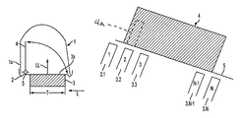
- FIGS. 1 , 1 ashow a first exemplary embodiment of the invention with a pivoting flap
- FIG. 2shows a second exemplary embodiment with a round flap
- FIG. 3shows a further exemplary embodiment with a round flap and a partition in the air box
- FIG. 4shows a modified exemplary embodiment with a partition and a flap with cutouts
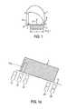
- FIG. 5shows a perspective illustration of the embodiment with the partition and half-round flap
- FIG. 6shows an exemplary embodiment with a flap in a partition
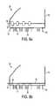
- FIGS. 7 a - cshow an exemplary embodiment with a rotary slide
- FIGS. 8 a - bshow an exemplary embodiment with a plurality of covering sections
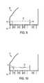
- FIG. 9shows an exemplary embodiment with a rolling louver
- FIG. 10shows a further exemplary embodiment with covering sections.
- FIG. 1shows, in a diagrammatic illustration, an air box 1 on the exit side of a charge intercooler (not entirely illustrated) which has a further air box on the entry side (not illustrated).
- the air box 1on which an air outlet (not illustrated) is arranged, is placed onto a tube plate 2 and is connected thereto.
- the tube plate 2is preferably produced from an aluminum material and has—perpendicularly to the plane of projection—a series of rims (not illustrated specifically) into which tubes 3 are inserted by their tube ends 3 a and are soldered.
- the air box 1can be produced from a plastic or aluminum material. Accordingly, the connection to the metallic tube plate 2 is a mechanical flared connection or a connection with a cohesive material joint, for example a soldered connection.
- the tubes 3have a rectangular cross section, the long side of which with the depth T lies parallel to the plane of projection.
- corrugated fins(not illustrated) which, together with the tubes 3 , form a heat exchanger unit or a “network” through which ambient air flows in the direction of an arrow L.
- a charge intercooler of this typeis usually arranged in the front region of an engine compartment (not illustrated) of a motor vehicle, generally together with further heat exchangers, such as, for example, a coolant cooler. In other embodiments, the charge intercooler is arranged in the vicinity of the vehicle engine.
- a pivotable flap 4whose pivot axis 5 is situated next to the tube end 3 a and in the region of the tube bottom 2 is arranged in the charge air box 1 .
- the flap 4is illustrated in an opened position, i.e. in an approximately parallel position to a side wall 1 a of the air box 1 .
- the flap 4is pivoted through 90 degrees, so that it comes to lie on the tube end 3 a and closes the latter.
- One or more cutouts 4 amay optionally be provided in the flap 4 to leave one or more of the individual tubes 3 uncovered.
- the actuation of the flap 4 and the mounting thereof in the air box 1are not illustrated and correspond to the prior art mentioned at the beginning.
- the flow through the charge air tube 3takes place in the direction of the arrow LL, i.e. the flap 4 is opened with the flow pressure and is closed counter to the flow pressure.
- a flap arrangement (not illustrated) in the air box on the charge air entry sideis likewise possible.
- the arrow LLwould then have to point in the opposite direction.
- FIG. 1 ashows an enlarged illustration of the flap 1 in relation to the tubes 3 . 1 , 3 . 2 , 3 . 3 , 3 .N ⁇ 1 and 3 .N which form a row R.
- the flap axis 5 of the flap 4is arranged somewhat above the tube ends and is mounted in a manner not illustrated.
- the flap 4is of rectangular design and has a height H and a width B.
- the height Hcorresponds at least to the depth T (cf. FIG. 1 ) of the tubes 3 , so that the tube cross sections are covered when the flap is closed.
- the width B in FIG. 1 ais selected in such a manner that the tubes 3 . 2 to 3 .N ⁇ 1 are covered when the flap 4 is closed, and only the two outer tubes 3 . 1 and 3 .N remain open and have charge air passing through them.
- only one tube or a plurality of tubesin particular more than two tubes, remains or remain open.
- These tubesare arranged on one or both edges of a respective tube row.
- tubes in the center of a tube rowmay also remain open.
- a plurality of flaps or preferably one flap with cutoutsare used, with the cutouts being assigned to the tubes which are to remain open.
- FIG. 2shows a further exemplary embodiment of the invention with an air box 6 on the outlet side which is connected in a plane 6 a to a tube plate (not illustrated) or to a heat exchanger unit with tubes opening into the tube plate.
- a charge air outlet 6 bis arranged on that side of the air box 6 which faces away from the plane 6 a .
- an angled partition 7which is composed of three regions 7 a , 7 b , 7 c and divides the air box 6 into two chambers, namely a first closable chamber 8 and a second passage chamber 9 .
- a round pivoting flap 10is arranged between the partition regions 7 b , 7 c .
- the closure positionis illustrated by the solid line 10 .
- a first number of tubes (not illustrated) open into the closable chamber 8and a second number of tubes (not illustrated) open into the passage chamber 9 , said second number—in accordance with the graphical illustration—being smaller than the first number, i.e. approximately in the ratio of 1:2 to 1:5.
- FIG. 3shows a modified exemplary embodiment of the invention with an air box 11 which, with a plane 11 a , adjoins a heat exchanger unit (not illustrated) of a charge intercooler (not illustrated).
- the air box 11has an exit connecting piece 11 b and a partition 12 (illustrated by dashed lines) which extends from the parting plane 11 a into the exit connecting piece 11 b .
- the partition 12divides the air box 11 into a first larger chamber 13 and a second smaller chamber 14 , a “passage chamber”.
- the chamber 13can be closed in the region of the exit connecting pipe 11 b by a round pivoting flap 15 , the circumference of which 15 a is illustrated by dashed lines.
- FIG. 4shows a modification of the exemplary embodiment according to FIG. 3 with the air box 11 and the partition 12 and the exit connecting pipe 11 b which has a circular cross section swung into the plane of projection by a dashed line 11 c .
- the cross section of the exit connecting pipe 11 bis divided by a section 12 a of the partition 12 into two partial cross sections 13 a , 14 a , the partial cross section 13 a which corresponds to the chamber 13 being closable by a round pivoting flap 16 .
- the pivoting flap 16appears in the drawing in its closed position as a solid line 16 and in its open position as a dashed line 11 c which is cut off by the partition section 12 a , so that the full circle 11 c (dashed line) is left open in the region of the partial cross section 14 a .
- the partial cross section 14 ais therefore always open.
- a perspective illustration of this embodimentis illustrated in the next figure.
- FIG. 5shows the exemplary embodiment according to FIG. 4 in a perspective illustration, with the same reference numbers being used for the same parts.
- the charge air box 11with the plane 11 a , adjoins a tube plate (not illustrated) which receives tube ends 17 a of rectangular tubes 17 .
- Corrugated fins 18are arranged between the rectangular tube 17 (tubes with an approximately rectangular flow cross section).
- the air box 11covers the entire tube plate (not entirely illustrated) and is divided by the transverse partition 12 into the chambers 13 and 14 .
- the air box 11narrows in the manner of a funnel to an entry connecting pipe (exit connecting pipe) 11 b which has a circular cross section 11 c .
- the circular cross sectionis divided by the partition 12 into the partial cross section 13 a (sketched dark) and the partial cross section 14 a .
- the half-round pivoting flap 16is arranged in the partial cross section 13 a and can either be pivoted about a flap axis 16 a or alternatively about a pivot axis 16 b . In both cases, the pivoting flap 16 closes or opens the partial cross section 13 a with the charge air flow through the chamber 13 and the tubes connected to it being prevented.
- the flow through the two tubes 17situated at the bottom of the drawing—which open into the chamber 14 is not interrupted. These flow passages always remain open.
- the activation of the flap 16is not illustrated; it takes place from the outside, for example in a manner as explained in the prior art explained at the beginning for exhaust gas heat exchangers.
- FIG. 6shows a further exemplary embodiment of the invention for a charge intercooler 20 which has a heat exchanger unit 21 , an upper air box 22 and a lower air box 23 , a “deflecting box”.
- the upper air box 22has an entry connecting pipe 24 and an exit connecting pipe 25 and a partition 26 which is arranged between the two and divides the air box 22 into an inlet chamber 24 a and an outlet chamber 25 a .
- the flowtherefore passes through the charge intercooler 20 in a U-shaped manner, i.e. in two directions corresponding to the arrows P, from the top downward and from the bottom upward.
- a round pivoting flap 27the outline 27 a of which is placed into the plane of projection as a broken line and the open position of which is marked is arranged in the partition 26 .
- the pivoting flap 27which can be activated from the outside in a manner not illustrated, therefore opens up a circular cross section 27 a in the partition 26 or closes the same.
- a standard charge air coolingtakes place, i.e. up to 100 percent.
- the flap 27is open, only a partial flow rather than the entire charge air flows through the unit 21 corresponding to the arrows P. The rest of the flow passes directly from the inlet connecting pipe 24 through the opening in the partition 26 to the exit connecting pipe 25 . Only a reduced cooling of the charge air therefore takes place, i.e. the charge air emerging from the exit connecting pipe 25 has a higher charge air temperature than in the case of standard cooling.
- FIGS. 7 a - ceach show a header box 30 of a charge intercooler, in which, for clarity, the side facing a tube/fin network of the charge intercooler is not illustrated.
- a rotary slide 31is illustrated in FIG. 7 a before it is installed in the header box, in FIG. 7 b in a first position for partial flow through the charge intercooler and in FIG. 7 c in a second position for complete flow through the charge intercooler.
- the rotary slide 31delimits a cylindrical partial volume of the header box 30 .
- part of the cylinder surface areais covered by the wall 44 of the rotary slide 31 and a remaining part of the cylinder surface area remains free.
- a shaft 43 as an extension of the cylinder axis of the cylindrical partial volumeserves as engagement point for a rotation of the rotary slide 31 about the cylinder axis, with the rotation being driven, for example, by means of an actuator, such as an electric stepping motor, a negative pressure or positive pressure cell or the like.
- a rotation of this typeenables a specific displacement of the wall 44 along the cylinder surface area.
- a round opening 32 with an edge 36 in the header box 30forms that end surface of the cylinder volume which is situated at the top in FIGS. 7 a - c and serves to introduce the rotary slide 31 into the header box 30 .
- An end wall 33 of the rotary slide 31after it is installed, covers the opening 32 and, via the sealing surface 34 and the inner surface 35 of the edge 36 of the opening 32 , seals off the interior of the header box 30 from the surroundings.
- a round opening 37 in the header box 30forms that end surface of the cylinder volume which is situated at the bottom in FIGS. 7 a - c and serves for the admission of charge air to be cooled. For this reason, the opening 37 remains open and is also not covered by the rotary slide 31 .
- the header box 30furthermore has a partition 38 which divides the interior of the header box 30 into a first subchamber 39 and a second subchamber 40 .
- the first subchamber 39is connected in terms of flow to tubes of a first tube group of the tube/fin network (not illustrated) while the second subchamber 40 is connected in terms of flow to tubes of a second tube group of the tube/fin network.
- header box 30has reinforcing ribs 41 to stabilize its geometry during operation of the charge intercooler and a structure 42 for connection to a tube plate, the tube plate receiving the tube ends of the tube/fin network.
- the ratio of the number of tubes of the first tube group to the number of tubes of the second tube groupcorresponds approximately to the cross-sectional ratio of the subchambers 39 and 40 and is preferably around 1:1 to 1:10, particularly preferably around 1:2 to 1:5.
- the degree of this lowering of the heat outputarises from the ratio of the number of tubes of the first tube group to the overall number of tubes of the charge intercooler.
- the proportion of closed tubesis preferably 50% to 90%, particularly preferably 70% to 80%, of the entire number of tubes.
- FIGS. 8 a - bshow a header box 50 of a charge intercooler diagrammatically in cross section.
- the header box 50has a housing 54 and a tube plate 51 with openings for receiving the ends of tubes 52 , with corrugated fins 53 being arranged between the tubes 52 to enlarge the heat-transferring surface area.
- Covering sections 56which are arranged opposite the ends of some of the tubes 52 are fastened on a shaft 55 .
- the shaft 55is mounted rotatably on one side of the header box 50 and, on the other side thereof, is guided out of the header box 50 through an opening 57 .
- the shaft 55is in turn driven, for example, by means of an actuator, such as an electric stepping motor, a negative pressure or positive pressure cell.
- the covering sections 56In a first position ( FIG. 8 a ), the covering sections 56 extend parallel to the tubes 52 , so that charge air which enters the header box 50 can flow past the covering sections 56 into all of the tubes 52 .
- Rotation of the shaft 55 through, for example, 90°makes it possible to reach a second position ( FIG. 8 b ) in which the covering sections 56 cover some of the tubes 52 and therefore block them from the charge air. Charge air is therefore only applied to the remaining (uncovered) tubes, with the result that the heat output which can be removed from the charge air is lowered in comparison to normal operation.
- covering sectionsare mounted displacably, in particular via a shaft which is similar to the shaft 55 and is itself mounted displacably. From a position covering the tubes, the covering sections can be displaced in particular in the longitudinal direction of the tubes or perpendicularly thereto into a position opening up the tubes.
- FIG. 9shows a similarly constructed header box 60 likewise in a diagrammatic cross section.
- covering sections 61are not fastened on a rotatably mounted shaft but rather on a displaceable frame, a band, a chain or the like.
- the frame, the band or the chainare fastened, for example via a further chain or directly, to a roller 62 , so that a displacement of the covering sections 61 between a first and a second position can be achieved via a rotation of the roller 62 .
- a partition 64serves, on the one hand, to separate the tube ends 63 which are to be covered from the remaining tube ends and, on the other hand, to support the frame, the band or the chain for the covering section 61 .
- FIG. 10shows a further header box 70 in a diagrammatic cross section.
- Covering sections 71 , 72are designed as two-winged flaps which, in a first position ( 71 ), permit all of the tubes 73 to be acted upon and, in contrast, in a second position 72 , close some of the tubes 73 .
- the two wings of each covering section 71 , 72are moved toward one another for opening purposes but by contrast, for closing purposes, are moved away from one another.
Landscapes
- Engineering & Computer Science (AREA)
- Physics & Mathematics (AREA)
- Thermal Sciences (AREA)
- Mechanical Engineering (AREA)
- General Engineering & Computer Science (AREA)
- Chemical & Material Sciences (AREA)
- Combustion & Propulsion (AREA)
- Heat-Exchange Devices With Radiators And Conduit Assemblies (AREA)
- Control Of Direct Current Motors (AREA)
- Electric Propulsion And Braking For Vehicles (AREA)
Abstract
Description
Claims (11)
Applications Claiming Priority (4)
| Application Number | Priority Date | Filing Date | Title |
|---|---|---|---|
| DE10346540 | 2003-10-02 | ||
| DE10346540 | 2003-10-02 | ||
| DE10346540.5 | 2003-10-02 | ||
| PCT/EP2004/010876WO2005033489A1 (en) | 2003-10-02 | 2004-09-29 | Charge intercooler for a motor vehicle |
Publications (2)
| Publication Number | Publication Date |
|---|---|
| US20070175612A1 US20070175612A1 (en) | 2007-08-02 |
| US8225849B2true US8225849B2 (en) | 2012-07-24 |
Family
ID=34399334
Family Applications (1)
| Application Number | Title | Priority Date | Filing Date |
|---|---|---|---|
| US10/574,223Expired - Fee RelatedUS8225849B2 (en) | 2003-10-02 | 2004-09-29 | Charge intercooler for a motor vehicle |
Country Status (5)
| Country | Link |
|---|---|
| US (1) | US8225849B2 (en) |
| EP (1) | EP1671020B1 (en) |
| AT (1) | ATE464459T1 (en) |
| DE (2) | DE102004047901A1 (en) |
| WO (1) | WO2005033489A1 (en) |
Cited By (8)
| Publication number | Priority date | Publication date | Assignee | Title |
|---|---|---|---|---|
| US20110017425A1 (en)* | 2007-11-15 | 2011-01-27 | Guillaume Bourgoin | Heat Exchanger For An Air Supply Circuit Of A Motor Vehicle Engine |
| US20130306038A1 (en)* | 2010-12-10 | 2013-11-21 | Valeo Systemes Thermiques | Device For Channeling A Flow Of Feed Gas For An Internal Combustion Engine |
| US20140026870A1 (en)* | 2012-07-26 | 2014-01-30 | Ford Global Technologies, Llc | Charge air cooler control system and method |
| US20140047833A1 (en)* | 2012-08-20 | 2014-02-20 | Ford Global Technologies, Llc | Method for controlling a variable charge air cooler |
| US20140190673A1 (en)* | 2011-06-30 | 2014-07-10 | Valeo Systemes Thermiques | Heat Exchanger, Particularly For A Motor Vehicle |
| US20180156165A1 (en)* | 2016-12-07 | 2018-06-07 | Ford Global Technologies, Llc | Charge air cooler with an integrated bypass |
| US10378430B2 (en)* | 2017-05-11 | 2019-08-13 | Hyundai Motor Company | Engine system having integrated intercooler |
| US10690233B2 (en)* | 2016-07-27 | 2020-06-23 | Ford Global Technologies, Llc | Bypass control for U-flow transmission oil coolers |
Families Citing this family (29)
| Publication number | Priority date | Publication date | Assignee | Title |
|---|---|---|---|---|
| SE528197C2 (en)* | 2005-02-17 | 2006-09-26 | Scania Cv Ab | Intercooler |
| SE529343C2 (en)* | 2005-11-28 | 2007-07-10 | Volvo Lastvagnar Ab | Charge air cooler and air distribution chamber for use in a charge air cooler |
| DE102006003447B4 (en)* | 2006-01-25 | 2008-04-03 | Daimler Ag | Exhaust gas cooler for an internal combustion engine |
| DE102006011727B3 (en)* | 2006-03-14 | 2007-11-22 | Webasto Ag | Combined heating / hot water system for mobile applications |
| SE529731C2 (en)* | 2006-03-21 | 2007-11-06 | Scania Cv Ab | Radiator arrangement of a vehicle |
| FR2899648B1 (en)* | 2006-04-11 | 2010-06-18 | Peugeot Citroen Automobiles Sa | RADIATOR COLLECTOR OF EXHAUST AIR COOLING |
| DE102006048485A1 (en)* | 2006-10-11 | 2008-04-17 | Behr Gmbh & Co. Kg | Charge air cooling device for an internal combustion engine, system with a charge air cooling device |
| EP3012570B1 (en) | 2007-04-11 | 2021-07-21 | MAHLE Behr GmbH & Co. KG | Heat exchanger |
| DE102007029036B4 (en) | 2007-06-23 | 2019-07-18 | Volkswagen Ag | Intercooler for an internal combustion engine |
| DE102007040793A1 (en)* | 2007-08-28 | 2009-03-05 | Behr Gmbh & Co. Kg | heat exchangers |
| DE102007043992B4 (en) | 2007-09-14 | 2009-08-27 | Pierburg Gmbh | Charge air module for an internal combustion engine |
| DE102008009152A1 (en)* | 2008-02-14 | 2009-08-20 | Volkswagen Ag | Charge-air cooler for internal combustion engine i.e. turbocharged internal-combustion engine, of motor vehicle, has two regions forming partial-surface of heat exchanger surface, where air is supplied to regions by flow guide element |
| FR2934329A1 (en)* | 2008-07-25 | 2010-01-29 | Peugeot Citroen Automobiles Sa | Rectangular supercharged air cooling case for e.g. diesel engine, of motor vehicle, has supercharged air inlet situated on its lower wall, air choke flap provided at its outlet, and coolant circulator circulating coolant in case |
| DE102010011373A1 (en)* | 2009-04-17 | 2010-10-21 | Behr Gmbh & Co. Kg | Charge air duct for an internal combustion engine |
| DE102009035086A1 (en) | 2009-07-28 | 2011-02-10 | Behr Gmbh & Co. Kg | Heat exchanger |
| DE102010033125A1 (en) | 2010-08-03 | 2012-02-09 | Daimler Ag | Heat exchanger device for use as e.g. intercooler for combustion engine of motor car, has bypass valve arranged in inlet region or exhaust region and connected with heat exchanger region that is connected with exhaust region |
| DE102011001462A1 (en)* | 2011-03-22 | 2012-09-27 | Pierburg Gmbh | Heat exchanger used for internal combustion engine of motor vehicle, has U-shaped partition plate that is clamped between ribs of housing portion, so that inlet from which fluid flows into sub-channels of coolant channel is closed |
| DE102011080204A1 (en) | 2011-08-01 | 2013-02-07 | Behr Gmbh & Co. Kg | Collecting box for heat exchanger such as intercooler used in motor vehicle e.g. motor car, has box wall that is provided with stiffening ribs which are aligned parallel to spread side of bottom portion at which box casing is closed |
| FI123990B (en)* | 2011-11-24 | 2014-01-31 | Waertsilae Finland Oy | End cover for a charge air cooler |
| US9080499B2 (en)* | 2012-08-20 | 2015-07-14 | Ford Global Technologies, Llc | Method for controlling a variable charge air cooler |
| US9599012B2 (en)* | 2012-12-30 | 2017-03-21 | General Electric Company | Charge air cooler cover and turbocharger bracket |
| US9464562B2 (en)* | 2013-05-02 | 2016-10-11 | Ford Global Technologies, Llc | Variable valve system to reduce condensation in a charge air cooler |
| JP6197644B2 (en) | 2013-12-26 | 2017-09-20 | マツダ株式会社 | Engine intake system |
| GB2531063B (en)* | 2014-10-10 | 2017-01-25 | Ford Global Tech Llc | A charge air cooler for a forced induction engine |
| US9689353B2 (en)* | 2015-08-27 | 2017-06-27 | GM Global Technology Operations LLC | Charge air cooler device |
| US9958219B2 (en)* | 2015-11-20 | 2018-05-01 | Denso International America, Inc. | Heat exchanger and dynamic baffle |
| DE102017210793A1 (en)* | 2017-06-27 | 2018-12-27 | Mahle International Gmbh | Cooling unit, control unit and method for controlling a condensate amount in a refrigeration unit |
| FR3072453B1 (en)* | 2017-10-13 | 2019-11-08 | Valeo Systemes Thermiques | HEAT EXCHANGER WITH DEVICE FOR SHUTTING CIRCULATING CONDUITS OF A GAS TO BE COOLED |
| KR20210066557A (en)* | 2019-11-28 | 2021-06-07 | 현대자동차주식회사 | Intercooler of vehicle |
Citations (62)
| Publication number | Priority date | Publication date | Assignee | Title |
|---|---|---|---|---|
| US447285A (en)* | 1891-03-03 | albergee | ||
| US687735A (en)* | 1900-08-11 | 1901-12-03 | R j cox | Heating device for liquids. |
| US780736A (en)* | 1903-09-02 | 1905-01-24 | Elmer S Stack | Water-heater. |
| US1918966A (en)* | 1930-06-20 | 1933-07-18 | Gen Chemical Corp | Apparatus for treating gas |
| US2063436A (en)* | 1931-02-24 | 1936-12-08 | Frederic W Hild | Multiflow cooling for internal combustion engines |
| US2076287A (en)* | 1934-04-21 | 1937-04-06 | Samuel P Arnold | Automobile heater |
| US2291637A (en)* | 1941-07-28 | 1942-08-04 | Kohlmann Walter | Lubricant cooling device |
| US2670933A (en)* | 1950-02-24 | 1954-03-02 | Thomas J Bay | Engine cooling apparatus |
| US2908485A (en)* | 1956-11-27 | 1959-10-13 | Exxon Research Engineering Co | Process using fluidized solids |
| US3034770A (en)* | 1959-09-16 | 1962-05-15 | Continental Aviat & Eng Corp | Heat exchanger |
| US3122202A (en)* | 1960-06-14 | 1964-02-25 | Harry J Scharres | Apparatus for heating and cooling air |
| US3353590A (en)* | 1965-07-12 | 1967-11-21 | Holman And Moody Inc | Unitary oil filtering and cooling attachment for internal combustion engines |
| US3440833A (en)* | 1967-11-09 | 1969-04-29 | United Aircraft Prod | Vapor cycle refrigeration system |
| US3513907A (en)* | 1968-04-17 | 1970-05-26 | United Aircraft Prod | Plural mode heat exchange apparatus |
| US3514967A (en)* | 1968-06-20 | 1970-06-02 | Whirlpool Co | Air conditioner control |
| US3656543A (en)* | 1970-05-25 | 1972-04-18 | Foster Wheeler Corp | Liquid metal heat exchanger |
| US3743011A (en)* | 1971-11-04 | 1973-07-03 | Modine Mfg Co | Heat exchanger |
| US3852147A (en)* | 1972-04-24 | 1974-12-03 | W Wilson | Heat exchanger |
| US4319630A (en)* | 1978-12-07 | 1982-03-16 | United Aircraft Products, Inc. | Tubular heat exchanger |
| DE3103198A1 (en) | 1981-01-30 | 1982-08-26 | Oskar Dr.-Ing. 8031 Stockdorf Schatz | Heat exchanger for operating with exhaust gases from reciprocating engines, in particular for heating motor vehicles |
| JPS5862495A (en)* | 1981-10-07 | 1983-04-13 | Hitachi Zosen Corp | Heat exchanger |
| US4385496A (en)* | 1979-10-24 | 1983-05-31 | Nissan Motor Co., Ltd. | Intake system for internal combustion engine provided with supercharger |
| DE3218984A1 (en) | 1982-05-19 | 1983-11-24 | Oskar Dr.-Ing. 8035 Gauting Schatz | Heat exchanger arrangement for operation using the exhaust gases of a piston engine |
| US4432410A (en)* | 1980-05-05 | 1984-02-21 | Valeo | Heat exchanger, in particular for a cooling circuit of a motor vehicle engine |
| JPS59145325A (en) | 1983-02-08 | 1984-08-20 | Toyo Radiator Kk | Heat exchanger for supercharged air |
| JPS59190425A (en) | 1983-04-12 | 1984-10-29 | Mitsubishi Heavy Ind Ltd | Suction device of internal-combustion engine with air cooler |
| JPS6050225A (en) | 1983-08-27 | 1985-03-19 | Hino Motors Ltd | Turbosupercharged engine with intercooler |
| US4561496A (en)* | 1983-01-25 | 1985-12-31 | Borsig Gmbh | Heat exchanger for the cooling of gases, particularly from the synthesis of ammonia |
| US4593749A (en)* | 1981-01-30 | 1986-06-10 | Oskar Schatz | Process for increasing the heat flow density of heat exchangers working with at least one high-velocity gaseous medium, and a heat exchanger apparatus for undertaking the process |
| JPS61237998A (en) | 1985-04-15 | 1986-10-23 | Toyo Radiator Kk | Radiator for supercharger incorporating supercharged air bypassing device |
| JPS6246194A (en) | 1985-08-26 | 1987-02-28 | Toyo Radiator Kk | Bypass valve device of intercooler for supercharger of engine |
| US4887664A (en)* | 1987-12-07 | 1989-12-19 | Westinghouse Electric Corp. | Heat exchanger system having adjustable heat transfer capacity |
| US4993367A (en)* | 1988-08-18 | 1991-02-19 | Borsig Gmbh | Heat exchanger |
| US5152144A (en)* | 1990-09-19 | 1992-10-06 | Cummins Engine Company, Inc. | Air to air heat exchanger internal bypass |
| US5452686A (en)* | 1993-03-26 | 1995-09-26 | Haldor Topsoe A/S | Waste heat boiler |
| US5732688A (en)* | 1996-12-11 | 1998-03-31 | Cummins Engine Company, Inc. | System for controlling recirculated exhaust gas temperature in an internal combustion engine |
| US5911212A (en)* | 1996-05-20 | 1999-06-15 | Benson; Steven R. | Priority valve for an intercooled engine |
| DE19857435A1 (en) | 1997-12-22 | 1999-06-24 | Valeo Thermique Moteur Sa | heat exchanger |
| US5950715A (en)* | 1995-06-16 | 1999-09-14 | Alfa Laval Ab | Plate heat exchanger |
| US6052995A (en)* | 1996-09-12 | 2000-04-25 | Robert Bosch Gmbh | Valve for an internal combustion engine, and an internal combustion engine including the valve |
| US6141961A (en)* | 1998-03-11 | 2000-11-07 | Ecia-Equipments Et Composants Pour L'industrie Automobile | Exhaust element with heat exchanger |
| DE19962863A1 (en) | 1999-12-24 | 2001-06-28 | Behr Gmbh & Co | Heat exchanger to transfer heat between exhaust gas of motor vehicle's internal combustion engine and cooling medium has bypass passage allocated to heat exchange region and flowed through by part of exhaust gas stream |
| DE19962861A1 (en) | 1999-12-24 | 2001-06-28 | Behr Gmbh & Co | Heat transfer device for charge air for vehicles, with flow guide plate parallel to tube bottom of air outlet collection chamber |
| US6330910B1 (en)* | 1999-03-03 | 2001-12-18 | Easton Bennett | Heat exchanger for a motor vehicle exhaust |
| US20030111211A1 (en)* | 2000-01-21 | 2003-06-19 | Stonehouse Matthew Thomas Graham | Exhaust gas heat exchanger |
| DE10203003A1 (en) | 2002-01-26 | 2003-08-07 | Behr Gmbh & Co | Exhaust gas heat exchanger |
| EP1336736A2 (en) | 2002-02-14 | 2003-08-20 | Delphi Technologies, Inc. | Intercooler for an engine |
| US20030159801A1 (en)* | 2001-06-01 | 2003-08-28 | Koenig Robert Peter | Coil capacity modulator |
| US6807955B2 (en)* | 2000-07-28 | 2004-10-26 | Honeywell International, Inc. | Exhaust gas cooler with bypass tube and exhaust gas recirculation valve |
| US20050028796A1 (en)* | 2003-08-07 | 2005-02-10 | Mack Trucks, Inc. | Cooler bypass valve system and method |
| US20050081523A1 (en)* | 2003-10-16 | 2005-04-21 | Thomas Breitling | Charged internal combustion engine |
| US20050269062A1 (en)* | 2002-08-28 | 2005-12-08 | Pascal Guerrero | Heat exchange unit for a motor vehicle and system comprising said unit |
| US7055584B2 (en)* | 2003-06-18 | 2006-06-06 | Modine Manufacturing Company | Heat exchanger with valve |
| US20070157983A1 (en)* | 2004-02-09 | 2007-07-12 | Behr Gmbh & Co. Kg | Arrangement for cooling the exhaust gas of a motor vehicle |
| US7264040B2 (en)* | 2003-01-31 | 2007-09-04 | Et Us Holdings Llc | Exhaust gas heat exchanger and bypass assembly |
| US20070204925A1 (en)* | 2002-06-24 | 2007-09-06 | Fok Bolderheij | Multifunctional faucet |
| US7305976B1 (en)* | 2006-05-17 | 2007-12-11 | International Engine Intellectual Property Company, Llc | Engine heater and method |
| US7353865B2 (en)* | 2003-09-05 | 2008-04-08 | Arvinmeritor Technology, Llc | Method for controlling a valve for an exhaust system |
| US7412945B2 (en)* | 2005-12-01 | 2008-08-19 | Alstom Technology Ltd. | Waste heat boiler |
| US20090090495A1 (en)* | 2006-03-10 | 2009-04-09 | Behr Gmbh & Co. Kg | Heat Exchanger for a Motor Vehicle |
| US7584782B1 (en)* | 2006-08-28 | 2009-09-08 | Hamilton Sundstrand Corporation | Valve defining modulated and unmodulated flow paths |
| US7743816B2 (en)* | 2002-05-15 | 2010-06-29 | Behr Gmbh & Co. Kg | Switchable waste gas exchanger |
- 2004
- 2004-09-29WOPCT/EP2004/010876patent/WO2005033489A1/enactiveApplication Filing
- 2004-09-29DEDE102004047901Apatent/DE102004047901A1/ennot_activeWithdrawn
- 2004-09-29EPEP04765679Apatent/EP1671020B1/ennot_activeExpired - Lifetime
- 2004-09-29DEDE502004011048Tpatent/DE502004011048D1/ennot_activeExpired - Lifetime
- 2004-09-29ATAT04765679Tpatent/ATE464459T1/ennot_activeIP Right Cessation
- 2004-09-29USUS10/574,223patent/US8225849B2/ennot_activeExpired - Fee Related
Patent Citations (70)
| Publication number | Priority date | Publication date | Assignee | Title |
|---|---|---|---|---|
| US447285A (en)* | 1891-03-03 | albergee | ||
| US687735A (en)* | 1900-08-11 | 1901-12-03 | R j cox | Heating device for liquids. |
| US780736A (en)* | 1903-09-02 | 1905-01-24 | Elmer S Stack | Water-heater. |
| US1918966A (en)* | 1930-06-20 | 1933-07-18 | Gen Chemical Corp | Apparatus for treating gas |
| US2063436A (en)* | 1931-02-24 | 1936-12-08 | Frederic W Hild | Multiflow cooling for internal combustion engines |
| US2076287A (en)* | 1934-04-21 | 1937-04-06 | Samuel P Arnold | Automobile heater |
| US2291637A (en)* | 1941-07-28 | 1942-08-04 | Kohlmann Walter | Lubricant cooling device |
| US2670933A (en)* | 1950-02-24 | 1954-03-02 | Thomas J Bay | Engine cooling apparatus |
| US2908485A (en)* | 1956-11-27 | 1959-10-13 | Exxon Research Engineering Co | Process using fluidized solids |
| US3034770A (en)* | 1959-09-16 | 1962-05-15 | Continental Aviat & Eng Corp | Heat exchanger |
| US3122202A (en)* | 1960-06-14 | 1964-02-25 | Harry J Scharres | Apparatus for heating and cooling air |
| US3353590A (en)* | 1965-07-12 | 1967-11-21 | Holman And Moody Inc | Unitary oil filtering and cooling attachment for internal combustion engines |
| US3440833A (en)* | 1967-11-09 | 1969-04-29 | United Aircraft Prod | Vapor cycle refrigeration system |
| US3513907A (en)* | 1968-04-17 | 1970-05-26 | United Aircraft Prod | Plural mode heat exchange apparatus |
| US3514967A (en)* | 1968-06-20 | 1970-06-02 | Whirlpool Co | Air conditioner control |
| US3656543A (en)* | 1970-05-25 | 1972-04-18 | Foster Wheeler Corp | Liquid metal heat exchanger |
| US3743011A (en)* | 1971-11-04 | 1973-07-03 | Modine Mfg Co | Heat exchanger |
| US3852147A (en)* | 1972-04-24 | 1974-12-03 | W Wilson | Heat exchanger |
| US4319630A (en)* | 1978-12-07 | 1982-03-16 | United Aircraft Products, Inc. | Tubular heat exchanger |
| US4385496A (en)* | 1979-10-24 | 1983-05-31 | Nissan Motor Co., Ltd. | Intake system for internal combustion engine provided with supercharger |
| US4432410A (en)* | 1980-05-05 | 1984-02-21 | Valeo | Heat exchanger, in particular for a cooling circuit of a motor vehicle engine |
| DE3103198A1 (en) | 1981-01-30 | 1982-08-26 | Oskar Dr.-Ing. 8031 Stockdorf Schatz | Heat exchanger for operating with exhaust gases from reciprocating engines, in particular for heating motor vehicles |
| US4593749A (en)* | 1981-01-30 | 1986-06-10 | Oskar Schatz | Process for increasing the heat flow density of heat exchangers working with at least one high-velocity gaseous medium, and a heat exchanger apparatus for undertaking the process |
| JPS5862495A (en)* | 1981-10-07 | 1983-04-13 | Hitachi Zosen Corp | Heat exchanger |
| DE3218984A1 (en) | 1982-05-19 | 1983-11-24 | Oskar Dr.-Ing. 8035 Gauting Schatz | Heat exchanger arrangement for operation using the exhaust gases of a piston engine |
| US4561496A (en)* | 1983-01-25 | 1985-12-31 | Borsig Gmbh | Heat exchanger for the cooling of gases, particularly from the synthesis of ammonia |
| JPS59145325A (en) | 1983-02-08 | 1984-08-20 | Toyo Radiator Kk | Heat exchanger for supercharged air |
| JPS59190425A (en) | 1983-04-12 | 1984-10-29 | Mitsubishi Heavy Ind Ltd | Suction device of internal-combustion engine with air cooler |
| JPS6050225A (en) | 1983-08-27 | 1985-03-19 | Hino Motors Ltd | Turbosupercharged engine with intercooler |
| JPS61237998A (en) | 1985-04-15 | 1986-10-23 | Toyo Radiator Kk | Radiator for supercharger incorporating supercharged air bypassing device |
| JPS6246194A (en) | 1985-08-26 | 1987-02-28 | Toyo Radiator Kk | Bypass valve device of intercooler for supercharger of engine |
| US4887664A (en)* | 1987-12-07 | 1989-12-19 | Westinghouse Electric Corp. | Heat exchanger system having adjustable heat transfer capacity |
| US4993367A (en)* | 1988-08-18 | 1991-02-19 | Borsig Gmbh | Heat exchanger |
| US5152144A (en)* | 1990-09-19 | 1992-10-06 | Cummins Engine Company, Inc. | Air to air heat exchanger internal bypass |
| US5452686A (en)* | 1993-03-26 | 1995-09-26 | Haldor Topsoe A/S | Waste heat boiler |
| US5950715A (en)* | 1995-06-16 | 1999-09-14 | Alfa Laval Ab | Plate heat exchanger |
| US5911212A (en)* | 1996-05-20 | 1999-06-15 | Benson; Steven R. | Priority valve for an intercooled engine |
| US6052995A (en)* | 1996-09-12 | 2000-04-25 | Robert Bosch Gmbh | Valve for an internal combustion engine, and an internal combustion engine including the valve |
| US5732688A (en)* | 1996-12-11 | 1998-03-31 | Cummins Engine Company, Inc. | System for controlling recirculated exhaust gas temperature in an internal combustion engine |
| DE19857435A1 (en) | 1997-12-22 | 1999-06-24 | Valeo Thermique Moteur Sa | heat exchanger |
| US6141961A (en)* | 1998-03-11 | 2000-11-07 | Ecia-Equipments Et Composants Pour L'industrie Automobile | Exhaust element with heat exchanger |
| US6330910B1 (en)* | 1999-03-03 | 2001-12-18 | Easton Bennett | Heat exchanger for a motor vehicle exhaust |
| DE19962863A1 (en) | 1999-12-24 | 2001-06-28 | Behr Gmbh & Co | Heat exchanger to transfer heat between exhaust gas of motor vehicle's internal combustion engine and cooling medium has bypass passage allocated to heat exchange region and flowed through by part of exhaust gas stream |
| DE19962861A1 (en) | 1999-12-24 | 2001-06-28 | Behr Gmbh & Co | Heat transfer device for charge air for vehicles, with flow guide plate parallel to tube bottom of air outlet collection chamber |
| US20030111211A1 (en)* | 2000-01-21 | 2003-06-19 | Stonehouse Matthew Thomas Graham | Exhaust gas heat exchanger |
| US6807955B2 (en)* | 2000-07-28 | 2004-10-26 | Honeywell International, Inc. | Exhaust gas cooler with bypass tube and exhaust gas recirculation valve |
| US20030159801A1 (en)* | 2001-06-01 | 2003-08-28 | Koenig Robert Peter | Coil capacity modulator |
| DE10203003A1 (en) | 2002-01-26 | 2003-08-07 | Behr Gmbh & Co | Exhaust gas heat exchanger |
| US20050039729A1 (en)* | 2002-01-26 | 2005-02-24 | Behr Gmbh & Co Kg | Exhaust gas heat exchanger |
| US7168419B2 (en)* | 2002-01-26 | 2007-01-30 | Behr Gmbh & Co. Kg | Exhaust gas heat exchanger |
| US20060162706A1 (en)* | 2002-01-26 | 2006-07-27 | Behr Gmbh & Co. Kg | Exhaust gas heat exchanger |
| US7032577B2 (en)* | 2002-01-26 | 2006-04-25 | Behr Gmbh & Co. Kg | Exhaust gas heat exchanger |
| EP1336736A2 (en) | 2002-02-14 | 2003-08-20 | Delphi Technologies, Inc. | Intercooler for an engine |
| US7743816B2 (en)* | 2002-05-15 | 2010-06-29 | Behr Gmbh & Co. Kg | Switchable waste gas exchanger |
| US20070204925A1 (en)* | 2002-06-24 | 2007-09-06 | Fok Bolderheij | Multifunctional faucet |
| US20050269062A1 (en)* | 2002-08-28 | 2005-12-08 | Pascal Guerrero | Heat exchange unit for a motor vehicle and system comprising said unit |
| US7264040B2 (en)* | 2003-01-31 | 2007-09-04 | Et Us Holdings Llc | Exhaust gas heat exchanger and bypass assembly |
| US7055584B2 (en)* | 2003-06-18 | 2006-06-06 | Modine Manufacturing Company | Heat exchanger with valve |
| US7163005B2 (en)* | 2003-08-07 | 2007-01-16 | Mack Trucks, Inc. | Cooler bypass valve system and method |
| US7007680B2 (en)* | 2003-08-07 | 2006-03-07 | Mack Trucks, Inc. | Cooler bypass valve system and method |
| US20060016439A1 (en)* | 2003-08-07 | 2006-01-26 | Mack Trucks, Inc. | Cooler bypass valve system and method |
| US20050028796A1 (en)* | 2003-08-07 | 2005-02-10 | Mack Trucks, Inc. | Cooler bypass valve system and method |
| US7353865B2 (en)* | 2003-09-05 | 2008-04-08 | Arvinmeritor Technology, Llc | Method for controlling a valve for an exhaust system |
| DE10348136A1 (en) | 2003-10-16 | 2005-05-12 | Daimler Chrysler Ag | Internal combustion engine with charge |
| US20050081523A1 (en)* | 2003-10-16 | 2005-04-21 | Thomas Breitling | Charged internal combustion engine |
| US20070157983A1 (en)* | 2004-02-09 | 2007-07-12 | Behr Gmbh & Co. Kg | Arrangement for cooling the exhaust gas of a motor vehicle |
| US7412945B2 (en)* | 2005-12-01 | 2008-08-19 | Alstom Technology Ltd. | Waste heat boiler |
| US20090090495A1 (en)* | 2006-03-10 | 2009-04-09 | Behr Gmbh & Co. Kg | Heat Exchanger for a Motor Vehicle |
| US7305976B1 (en)* | 2006-05-17 | 2007-12-11 | International Engine Intellectual Property Company, Llc | Engine heater and method |
| US7584782B1 (en)* | 2006-08-28 | 2009-09-08 | Hamilton Sundstrand Corporation | Valve defining modulated and unmodulated flow paths |
Cited By (14)
| Publication number | Priority date | Publication date | Assignee | Title |
|---|---|---|---|---|
| US20110017425A1 (en)* | 2007-11-15 | 2011-01-27 | Guillaume Bourgoin | Heat Exchanger For An Air Supply Circuit Of A Motor Vehicle Engine |
| US8800637B2 (en)* | 2007-11-15 | 2014-08-12 | Valeo Systemes Thermiques | Heat exchanger including an air flow control valve |
| US9341149B2 (en)* | 2010-12-10 | 2016-05-17 | Valeo Systemes Thermiques | Device for channeling a flow of feed gas for an internal combustion engine |
| US20130306038A1 (en)* | 2010-12-10 | 2013-11-21 | Valeo Systemes Thermiques | Device For Channeling A Flow Of Feed Gas For An Internal Combustion Engine |
| US20140190673A1 (en)* | 2011-06-30 | 2014-07-10 | Valeo Systemes Thermiques | Heat Exchanger, Particularly For A Motor Vehicle |
| US9562466B2 (en)* | 2011-06-30 | 2017-02-07 | Valeo Systemes Thermiques | Heat exchanger for exchanging heat between a first fluid and a second fluid, both having U-circulation |
| US20140026870A1 (en)* | 2012-07-26 | 2014-01-30 | Ford Global Technologies, Llc | Charge air cooler control system and method |
| US9222447B2 (en)* | 2012-07-26 | 2015-12-29 | Ford Global Technologies, Llc | Charge air cooler control system and method |
| US20140047833A1 (en)* | 2012-08-20 | 2014-02-20 | Ford Global Technologies, Llc | Method for controlling a variable charge air cooler |
| US9169809B2 (en)* | 2012-08-20 | 2015-10-27 | Ford Global Technologies, Llc | Method for controlling a variable charge air cooler |
| US10006338B2 (en) | 2012-08-20 | 2018-06-26 | Ford Global Technologies, Llc | Method for controlling a variable charge air cooler |
| US10690233B2 (en)* | 2016-07-27 | 2020-06-23 | Ford Global Technologies, Llc | Bypass control for U-flow transmission oil coolers |
| US20180156165A1 (en)* | 2016-12-07 | 2018-06-07 | Ford Global Technologies, Llc | Charge air cooler with an integrated bypass |
| US10378430B2 (en)* | 2017-05-11 | 2019-08-13 | Hyundai Motor Company | Engine system having integrated intercooler |
Also Published As
| Publication number | Publication date |
|---|---|
| WO2005033489A1 (en) | 2005-04-14 |
| DE102004047901A1 (en) | 2005-06-09 |
| ATE464459T1 (en) | 2010-04-15 |
| US20070175612A1 (en) | 2007-08-02 |
| DE502004011048D1 (en) | 2010-05-27 |
| EP1671020A1 (en) | 2006-06-21 |
| EP1671020B1 (en) | 2010-04-14 |
Similar Documents
| Publication | Publication Date | Title |
|---|---|---|
| US8225849B2 (en) | Charge intercooler for a motor vehicle | |
| US7168419B2 (en) | Exhaust gas heat exchanger | |
| EP2602143B1 (en) | Cooling structure for vehicles | |
| AU781363B2 (en) | Vehicular cooling system | |
| EP1336736B1 (en) | Intercooler for an engine | |
| US7814966B2 (en) | Variable flow heat exchanger system and method | |
| CN103850779B (en) | Charger-air cooler ponent design | |
| US4756279A (en) | Control arrangement for the cooling air of air-liquid-cooled internal-combustion engines, particularly motor vehicles | |
| CN103906987B (en) | Laminated board exhaust recovery device | |
| US5152144A (en) | Air to air heat exchanger internal bypass | |
| US8813729B2 (en) | Charge air duct for an internal combustion engine | |
| US8596342B2 (en) | Heat exchanger housing, heat exchanger or modular unit having one or more heat exchangers, exhaust-gas recirculation system, charge-air supply system and use of the heat exchanger | |
| US20050081523A1 (en) | Charged internal combustion engine | |
| US6923166B2 (en) | Supercharging assembly for an internal combustion engine of a motor vehicle | |
| GB2414690A (en) | An emission control apparatus for an engine | |
| US20070199319A1 (en) | System and method for controlling engine charge air temperature | |
| US8100118B2 (en) | Exhaust gas valve | |
| KR20060034238A (en) | Gas temperature control method and heat exchange system | |
| JP2004194384A (en) | Battery cooling device for electric vehicles | |
| CN111845324A (en) | Cooling air supply equipment for motor vehicles | |
| US11976579B2 (en) | Exhaust component cooling | |
| US11619164B2 (en) | Shut-off member for channel connection and channel disconnection of a turbocharger, and internal combustion engine and vehicle with a shut-off member of this type | |
| KR20230086354A (en) | Egr cooler | |
| KR101015696B1 (en) | Intake system for heat engine with turbocharger | |
| JP2505788Y2 (en) | Engine intake system |
Legal Events
| Date | Code | Title | Description |
|---|---|---|---|
| AS | Assignment | Owner name:BEHR GMBH & CO. KG, GERMANY Free format text:ASSIGNMENT OF ASSIGNORS INTEREST;ASSIGNOR:HENDRIX, DANIEL;REEL/FRAME:018134/0255 Effective date:20060518 | |
| AS | Assignment | Owner name:BEHR GMBH & CO. KG, GERMANY Free format text:CORRECTIVE ASSIGNMENT TO CORRECT THE DOC DATE OF THE ASSIGNOR TO READ 05/16/2006 PREVIOUSLY RECORDED ON REEL 018134 FRAME 0255;ASSIGNOR:HENDRIX, DANIEL;REEL/FRAME:019519/0001 Effective date:20060516 Owner name:BEHR GMBH & CO. KG, GERMANY Free format text:CORRECTIVE ASSIGNMENT TO CORRECT THE DOC DATE OF THE ASSIGNOR TO READ 05/16/2006 PREVIOUSLY RECORDED ON REEL 018134 FRAME 0255. ASSIGNOR(S) HEREBY CONFIRMS THE ASSIGNMENT TO BEHR GMBH & CO. KG;ASSIGNOR:HENDRIX, DANIEL;REEL/FRAME:019519/0001 Effective date:20060516 | |
| STCF | Information on status: patent grant | Free format text:PATENTED CASE | |
| FPAY | Fee payment | Year of fee payment:4 | |
| MAFP | Maintenance fee payment | Free format text:PAYMENT OF MAINTENANCE FEE, 8TH YEAR, LARGE ENTITY (ORIGINAL EVENT CODE: M1552); ENTITY STATUS OF PATENT OWNER: LARGE ENTITY Year of fee payment:8 | |
| FEPP | Fee payment procedure | Free format text:MAINTENANCE FEE REMINDER MAILED (ORIGINAL EVENT CODE: REM.); ENTITY STATUS OF PATENT OWNER: LARGE ENTITY | |
| LAPS | Lapse for failure to pay maintenance fees | Free format text:PATENT EXPIRED FOR FAILURE TO PAY MAINTENANCE FEES (ORIGINAL EVENT CODE: EXP.); ENTITY STATUS OF PATENT OWNER: LARGE ENTITY | |
| STCH | Information on status: patent discontinuation | Free format text:PATENT EXPIRED DUE TO NONPAYMENT OF MAINTENANCE FEES UNDER 37 CFR 1.362 | |
| FP | Lapsed due to failure to pay maintenance fee | Effective date:20240724 |