US8225786B2 - Double-ended blower and volutes therefor - Google Patents
Double-ended blower and volutes thereforDownload PDFInfo
- Publication number
- US8225786B2 US8225786B2US11/704,325US70432507AUS8225786B2US 8225786 B2US8225786 B2US 8225786B2US 70432507 AUS70432507 AUS 70432507AUS 8225786 B2US8225786 B2US 8225786B2
- Authority
- US
- United States
- Prior art keywords
- gas
- cpap
- impeller
- motor
- nippv apparatus
- Prior art date
- Legal status (The legal status is an assumption and is not a legal conclusion. Google has not performed a legal analysis and makes no representation as to the accuracy of the status listed.)
- Expired - Fee Related, expires
Links
- 238000013016dampingMethods0.000claimsdescription12
- XAGFODPZIPBFFR-UHFFFAOYSA-NaluminiumChemical compound[Al]XAGFODPZIPBFFR-UHFFFAOYSA-N0.000claimsdescription10
- 229910052782aluminiumInorganic materials0.000claimsdescription9
- 230000003434inspiratory effectEffects0.000claimsdescription6
- 238000004891communicationMethods0.000claimsdescription4
- 229920001971elastomerPolymers0.000claimsdescription4
- 229920001296polysiloxanePolymers0.000claimsdescription3
- 230000000241respiratory effectEffects0.000claimsdescription3
- 230000029058respiratory gaseous exchangeEffects0.000claimsdescription3
- 229920002635polyurethanePolymers0.000claimsdescription2
- 239000004814polyurethaneSubstances0.000claimsdescription2
- 239000006260foamSubstances0.000claims1
- 230000005534acoustic noiseEffects0.000abstractdescription7
- 238000009423ventilationMethods0.000abstractdescription4
- 230000004044responseEffects0.000abstractdescription2
- 239000007789gasSubstances0.000description32
- 239000000463materialSubstances0.000description7
- 239000012530fluidSubstances0.000description6
- 238000000034methodMethods0.000description6
- 238000005495investment castingMethods0.000description5
- 229910052751metalInorganic materials0.000description5
- 239000002184metalSubstances0.000description5
- QVGXLLKOCUKJST-UHFFFAOYSA-Natomic oxygenChemical compound[O]QVGXLLKOCUKJST-UHFFFAOYSA-N0.000description3
- 238000002347injectionMethods0.000description3
- 239000007924injectionSubstances0.000description3
- 238000004519manufacturing processMethods0.000description3
- 208000001797obstructive sleep apneaDiseases0.000description3
- 229910052760oxygenInorganic materials0.000description3
- 239000001301oxygenSubstances0.000description3
- 230000007704transitionEffects0.000description3
- MYMOFIZGZYHOMD-UHFFFAOYSA-NDioxygenChemical compoundO=OMYMOFIZGZYHOMD-UHFFFAOYSA-N0.000description2
- 230000009286beneficial effectEffects0.000description2
- 229910001882dioxygenInorganic materials0.000description2
- 230000000694effectsEffects0.000description2
- 229920001821foam rubberPolymers0.000description2
- 150000002739metalsChemical class0.000description2
- 208000023504respiratory system diseaseDiseases0.000description2
- 238000007493shaping processMethods0.000description2
- 238000009987spinningMethods0.000description2
- 229910000838Al alloyInorganic materials0.000description1
- 241000258957AsteroideaSpecies0.000description1
- 206010014561EmphysemaDiseases0.000description1
- 229920000106Liquid crystal polymerPolymers0.000description1
- 239000004977Liquid-crystal polymers (LCPs)Substances0.000description1
- 229910000861Mg alloyInorganic materials0.000description1
- 229910000831SteelInorganic materials0.000description1
- 230000001133accelerationEffects0.000description1
- 239000000853adhesiveSubstances0.000description1
- 230000001070adhesive effectEffects0.000description1
- 238000005452bendingMethods0.000description1
- 238000005266castingMethods0.000description1
- 238000004590computer programMethods0.000description1
- 238000005094computer simulationMethods0.000description1
- 239000004020conductorSubstances0.000description1
- 230000008878couplingEffects0.000description1
- 238000010168coupling processMethods0.000description1
- 238000005859coupling reactionMethods0.000description1
- 239000000806elastomerSubstances0.000description1
- 238000005516engineering processMethods0.000description1
- 238000001595flow curveMethods0.000description1
- 230000020169heat generationEffects0.000description1
- JEIPFZHSYJVQDO-UHFFFAOYSA-Niron(III) oxideInorganic materialsO=[Fe]O[Fe]=OJEIPFZHSYJVQDO-UHFFFAOYSA-N0.000description1
- 238000005259measurementMethods0.000description1
- 230000007246mechanismEffects0.000description1
- 230000003647oxidationEffects0.000description1
- 238000007254oxidation reactionMethods0.000description1
- 239000004033plasticSubstances0.000description1
- 229920003023plasticPolymers0.000description1
- 238000004088simulationMethods0.000description1
- 239000010959steelSubstances0.000description1
- 238000010408sweepingMethods0.000description1
- 238000004804windingMethods0.000description1
Images


Classifications
- F—MECHANICAL ENGINEERING; LIGHTING; HEATING; WEAPONS; BLASTING
- F04—POSITIVE - DISPLACEMENT MACHINES FOR LIQUIDS; PUMPS FOR LIQUIDS OR ELASTIC FLUIDS
- F04D—NON-POSITIVE-DISPLACEMENT PUMPS
- F04D1/00—Radial-flow pumps, e.g. centrifugal pumps; Helico-centrifugal pumps
- A—HUMAN NECESSITIES
- A61—MEDICAL OR VETERINARY SCIENCE; HYGIENE
- A61M—DEVICES FOR INTRODUCING MEDIA INTO, OR ONTO, THE BODY; DEVICES FOR TRANSDUCING BODY MEDIA OR FOR TAKING MEDIA FROM THE BODY; DEVICES FOR PRODUCING OR ENDING SLEEP OR STUPOR
- A61M16/00—Devices for influencing the respiratory system of patients by gas treatment, e.g. ventilators; Tracheal tubes
- A61M16/0057—Pumps therefor
- A61M16/0066—Blowers or centrifugal pumps
- A61M16/0069—Blowers or centrifugal pumps the speed thereof being controlled by respiratory parameters, e.g. by inhalation
- A—HUMAN NECESSITIES
- A61—MEDICAL OR VETERINARY SCIENCE; HYGIENE
- A61M—DEVICES FOR INTRODUCING MEDIA INTO, OR ONTO, THE BODY; DEVICES FOR TRANSDUCING BODY MEDIA OR FOR TAKING MEDIA FROM THE BODY; DEVICES FOR PRODUCING OR ENDING SLEEP OR STUPOR
- A61M16/00—Devices for influencing the respiratory system of patients by gas treatment, e.g. ventilators; Tracheal tubes
- A61M16/08—Bellows; Connecting tubes ; Water traps; Patient circuits
- A61M16/0816—Joints or connectors
- A—HUMAN NECESSITIES
- A61—MEDICAL OR VETERINARY SCIENCE; HYGIENE
- A61M—DEVICES FOR INTRODUCING MEDIA INTO, OR ONTO, THE BODY; DEVICES FOR TRANSDUCING BODY MEDIA OR FOR TAKING MEDIA FROM THE BODY; DEVICES FOR PRODUCING OR ENDING SLEEP OR STUPOR
- A61M16/00—Devices for influencing the respiratory system of patients by gas treatment, e.g. ventilators; Tracheal tubes
- A61M16/08—Bellows; Connecting tubes ; Water traps; Patient circuits
- A61M16/0875—Connecting tubes
- F—MECHANICAL ENGINEERING; LIGHTING; HEATING; WEAPONS; BLASTING
- F04—POSITIVE - DISPLACEMENT MACHINES FOR LIQUIDS; PUMPS FOR LIQUIDS OR ELASTIC FLUIDS
- F04D—NON-POSITIVE-DISPLACEMENT PUMPS
- F04D17/00—Radial-flow pumps, e.g. centrifugal pumps; Helico-centrifugal pumps
- F04D17/08—Centrifugal pumps
- F04D17/10—Centrifugal pumps for compressing or evacuating
- F04D17/12—Multi-stage pumps
- F04D17/122—Multi-stage pumps the individual rotor discs being, one for each stage, on a common shaft and axially spaced, e.g. conventional centrifugal multi- stage compressors
- F—MECHANICAL ENGINEERING; LIGHTING; HEATING; WEAPONS; BLASTING
- F04—POSITIVE - DISPLACEMENT MACHINES FOR LIQUIDS; PUMPS FOR LIQUIDS OR ELASTIC FLUIDS
- F04D—NON-POSITIVE-DISPLACEMENT PUMPS
- F04D17/00—Radial-flow pumps, e.g. centrifugal pumps; Helico-centrifugal pumps
- F04D17/08—Centrifugal pumps
- F04D17/16—Centrifugal pumps for displacing without appreciable compression
- F04D17/164—Multi-stage fans, e.g. for vacuum cleaners
- F—MECHANICAL ENGINEERING; LIGHTING; HEATING; WEAPONS; BLASTING
- F04—POSITIVE - DISPLACEMENT MACHINES FOR LIQUIDS; PUMPS FOR LIQUIDS OR ELASTIC FLUIDS
- F04D—NON-POSITIVE-DISPLACEMENT PUMPS
- F04D25/00—Pumping installations or systems
- F04D25/16—Combinations of two or more pumps ; Producing two or more separate gas flows
- F04D25/166—Combinations of two or more pumps ; Producing two or more separate gas flows using fans
- F—MECHANICAL ENGINEERING; LIGHTING; HEATING; WEAPONS; BLASTING
- F04—POSITIVE - DISPLACEMENT MACHINES FOR LIQUIDS; PUMPS FOR LIQUIDS OR ELASTIC FLUIDS
- F04D—NON-POSITIVE-DISPLACEMENT PUMPS
- F04D27/00—Control, e.g. regulation, of pumps, pumping installations or pumping systems specially adapted for elastic fluids
- F04D27/004—Control, e.g. regulation, of pumps, pumping installations or pumping systems specially adapted for elastic fluids by varying driving speed
- F—MECHANICAL ENGINEERING; LIGHTING; HEATING; WEAPONS; BLASTING
- F04—POSITIVE - DISPLACEMENT MACHINES FOR LIQUIDS; PUMPS FOR LIQUIDS OR ELASTIC FLUIDS
- F04D—NON-POSITIVE-DISPLACEMENT PUMPS
- F04D29/00—Details, component parts, or accessories
- F04D29/58—Cooling; Heating; Diminishing heat transfer
- F04D29/582—Cooling; Heating; Diminishing heat transfer specially adapted for elastic fluid pumps
- Y—GENERAL TAGGING OF NEW TECHNOLOGICAL DEVELOPMENTS; GENERAL TAGGING OF CROSS-SECTIONAL TECHNOLOGIES SPANNING OVER SEVERAL SECTIONS OF THE IPC; TECHNICAL SUBJECTS COVERED BY FORMER USPC CROSS-REFERENCE ART COLLECTIONS [XRACs] AND DIGESTS
- Y02—TECHNOLOGIES OR APPLICATIONS FOR MITIGATION OR ADAPTATION AGAINST CLIMATE CHANGE
- Y02B—CLIMATE CHANGE MITIGATION TECHNOLOGIES RELATED TO BUILDINGS, e.g. HOUSING, HOUSE APPLIANCES OR RELATED END-USER APPLICATIONS
- Y02B30/00—Energy efficient heating, ventilation or air conditioning [HVAC]
- Y02B30/70—Efficient control or regulation technologies, e.g. for control of refrigerant flow, motor or heating
Definitions
- the present inventionrelates to an apparatus for supplying breathable gas to a human, used in, for example, Continuous Positive Airway Pressure (CPAP) treatment of Obstructive Sleep Apnea (OSA), other respiratory diseases and disorders such as emphysema, or the application of assisted ventilation.
- CPAPContinuous Positive Airway Pressure
- OSAObstructive Sleep Apnea
- assisted ventilationa respiratory system for supplying breathable gas to a human, used in, for example, Continuous Positive Airway Pressure (CPAP) treatment of Obstructive Sleep Apnea (OSA), other respiratory diseases and disorders such as emphysema, or the application of assisted ventilation.
- CPAPContinuous Positive Airway Pressure
- OSAObstructive Sleep Apnea
- assisted ventilationemphysema
- CPAP treatment of OSAinvolves the delivery of a pressurized breathable gas, usually air, to a patient's airways using a conduit and mask.
- Gas pressures employed for CPAPcan range from 4 cm H 2 O to 28 cm H 2 O, at flow rates of up to 180 L/min (measured at the mask), depending on patient requirements.
- the pressurized gasacts as a pneumatic splint for the patient's airway, preventing airway collapse, especially during the inspiratory phase of respiration.
- the pressure at which a patient is ventilated during CPAPis varied according to the phase of the patient's breathing cycle.
- the ventilation apparatusmay be pre-set to deliver two pressures, an inspiratory positive airway pressure (IPAP) during the inspiration phase of the respiratory cycle, and an expiratory positive airway pressure (EPAP) during the expiration phase of the respiratory cycle.
- IPAPinspiratory positive airway pressure
- EPAPexpiratory positive airway pressure
- the air supply to the patientis pressurized by a blower having a single impeller.
- the impelleris enclosed in a volute, or housing, in which the entering gas is trapped while pressurized by the spinning impeller.
- the pressurized gasgradually leaves the volute and travels to the patient's mask.
- blower and impellercan be configured to produce the two different pressures, IPAP and EPAP, that are required in an ideal CPAP system.
- a first methodis to set the motor/impeller to produce a constant high pressure and then employ a diverter valve arrangement that modulates the high pressure to achieve the required IPAP and EPAP pressures.
- CPAP systems according to the first methodare called single-speed bi-level systems with diverters.
- a second methodis to accelerate the motor that drives the impeller to directly produce IPAP and EPAP pressures.
- CPAP systems according to the second methodare called variable-speed bi-level systems.
- Variable-speed bi-level CPAP systemshave a number of particular disadvantages.
- a first disadvantageis that in order to switch rapidly between IPAP and EPAP, the impeller must be accelerated and decelerated rapidly. This causes excessive stress on the impeller, motor, and bearings. However, if the impeller is accelerated slowly, the pressure rise may be unsatisfactorily slow, and thus, the patient may not receive adequate treatment.
- acoustic noiserefers to acoustic noise that is overly loud, as well as acoustic noise which occurs at a frequency that is irritating to the user, regardless of its volume.
- design engineersare often forced to make a compromise, sacrificing optimal pressure and flow characteristics in favor of achieving a desired peak pressure.
- the present inventionin one aspect, relates to variable speed blowers providing faster pressure rise time with increased reliability and less acoustic noise.
- Blowers according to the present inventioncomprise a gas flow path between a gas inlet and a gas outlet, a motor, and an impeller assembly.
- the impeller assemblymay include a shaft in communication with the motor for rotational motion about a first axis and first and second impellers coupled, e.g., fixedly secured, to the shaft.
- the impellersare placed in fluid communication with one another by the gas flow path such that both impellers are disposed between the gas inlet and the gas outlet to cooperatively pressurize gas flowing from the gas inlet to the gas outlet.
- the impellersare disposed in series between the gas inlet and the gas outlet.
- the blowermay also comprise a housing, portions of the housing being disposed around each of the first and second impellers.
- the housingmay include first and second volutes, the first volute containing gas flow around the first impeller and the second volute containing gas flow around the second impeller.
- the gas inletmay be located in the first volute and the gas outlet may be located in the second volute.
- the impellersmay be arranged such that they are vertically spaced from one another along the first axis. In particular, they may be disposed at opposite ends, respectively, of the blower housing.
- a blower according to the present inventionmay have varying configurations.
- the two impellersare designed to rotate in the same direction.
- the two impellersare designed to rotate in opposite directions.
- Another aspect of the inventionrelates to an in-plane transitional scroll volute for use in either a double- or single-ended blower.
- the in-plane transitional scroll volutegradually directs pressurized air away from a spinning impeller.
- FIG. 1 aschematically illustrates CPAP/NIPPV apparatus according to one embodiment of the present invention
- FIG. 1is a perspective view of a double-ended blower according to a first embodiment of the present invention
- FIG. 2is a partially sectional perspective view of the double-ended blower of FIG. 1 ;
- FIG. 3is a perspective view of a double-ended blower according to a second embodiment of the present invention.
- FIG. 4is a sectional perspective view of the double-ended blower of FIG. 3 ;
- FIG. 5is a rear perspective view of the double-ended blower of FIG. 3 , illustrating the flow therethrough;
- FIG. 6is a perspective view of an in-plane transitional scroll volute suitable for use in blowers according to the present invention.
- FIG. 7is an exploded perspective view of a double-ended blower according to another embodiment of the present invention.
- FIG. 8is an assembled perspective view of the double-ended blower of FIG. 7 from one side;
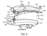
- FIG. 9is an assembled perspective view of the double-ended blower of FIG. 7 from another side.
- FIG. 1 aschematically illustrates a CPAP/NIPPV apparatus 1 according to a sample embodiment of the present invention.
- Apparatus 1includes a flow generator 2 , a patient interface 3 in the form of a mask, and an air delivery tube 4 fluidly coupling the flow generator 2 and the patient interface.
- the flow generatorincludes a blower 5 , as described in more detail herein.
- the airpath 116 of blower 100is comprised of piping that extends from the first volute 112 to the second volute 113 , the terminal ends of the airpath 116 being contoured around, and gradually fusing with, the body of blower 100 proximate to the volutes 112 , 113 to form a single, integral structure.
- the airpath 116may be comprised of rigid piping that is integrally molded with the other components of the blower 100 , or it may be comprised of flexible piping (e.g., metallic or plastic flexible piping).
- Blower 100has a single air intake 118 positioned such that air, or another suitable gas, flows directly into the first volute 112 and can be drawn in by the turning impeller 114 inside the first volute 112 . Once drawn into the air intake 118 , the air is circulated and pressurized by the motion of the impeller 114 before gradually exiting the volute 112 and entering the airpath 116 . Once in the airpath 116 , the air travels to the second volute 113 , where it is further circulated and pressurized by the impeller 115 of the second volute 113 before exiting the blower 100 through the outflow conduit 120 .
- the path of the air in blower 100is indicated by the arrows in FIG. 1 . As shown, in blower 100 , air from the first volute 112 travels along a relatively straight section of the airpath 116 and enters the second volute 113 through an intake cavity just above the second volute 113 (not shown in FIG. 1 ).
- Blower 100could have two air intakes 118 , one for each volute 112 , 113 , if the impellers 114 , 115 are designed to work in parallel, rather than in series. This type of parallel impeller arrangement may be beneficial if installed in a low-pressure CPAP device requiring high flow rates. However, other means for generating high flow rates in a low-pressure CPAP device are known in the art.
- the design of the airpath 116can effect the overall performance of the blower 100 .
- several design considerationsinfluence the design of an airpath for use in blowers according to the present invention.
- airpaths to be used in blowers according to the present inventionare most advantageously configured to provide low flow resistance, because low flow resistance in the airpath minimizes the pressure drop between the two volutes 112 , 113 in the blower.
- airpathare best configured such that the air entering the second volute 113 enters from a direction for which the blades of the impeller 115 were designed. (As will be described in more detail below, the two impellers of a blower according to the present invention may be designed to spin in the same or different directions.)
- airpaths for blowers according to the present inventionare most advantageously of a compact design.
- the airpath 116 of the embodiment depicted in FIG. 1has a long, relatively straight section because the relatively straight section is one of the shortest possible paths between the two volutes 112 , 113 .
- the airpath 116need not be straight at all.
- Blowers according to the inventionmay be designed manually, using prototypes and experimental measurements of air flows and pressures in those prototypes to optimize the design of the airpath 116 and other components. Alternatively, they may be designed, either as a whole or in part, by using computational fluid dynamics computer simulation programs.
- a variety of computational fluid dynamics programsare known in the art.
- Computational fluid dynamics programs particularly suited for the design of blowers according to the inventioninclude FLOWORKS (NIKA GmbH, Sottrum, Germany), ANSYS/FLOTRAN (Ansys, Inc., Canonsburg, Pa., USA), and CFX (AEA Technology Engineering Software, Inc., El Dorado Hills, Calif., USA).
- Such simulation programsgive the user the ability to see the effects of airpath design changes on a simulated gas flow.
- each voluteis designed to retain the gas around the impeller for a short period of time, and to permit a gradual exit of gas into the airpath.
- the exact configuration of the airpathmay depend on many factors, including the configuration of the volutes and the “handedness,” or direction of airflow, around each impeller.
- the design of the volutesis an art unto itself, as improperly designed volutes may cause a noise, or may interfere with the generation of the desired pressure and flow characteristics.
- the computational fluid dynamics computer programs described abovemay also be useful in designing the volutes, although the number of variables involved in volute design usually precludes the volute from being entirely computer-designed.
- volutes 112 , 113may provide too abrupt of a transition into the airpath 116 .
- An abrupt transition between the volute 112 , 113 and the airpath 116usually leaves a forked path or “lip” around the opening. When the impeller blades pass by this lip, a noise called “blade passing frequency” is created.
- Double-ended blowers according to the present inventionare particularly suited for use with volutes that are constructed to reduce the occurrence of “blade passing frequency” and other noise.
- FIG. 6is a perspective view of an in-plane transitional scroll volute 300 suitable for use in a blower according to the present invention. Additionally, the volute 300 may be employed in any conventional blower apparatus. In the view of FIG. 6 , the volute 300 is provided with its own motor 302 , although it may be adapted for use in a double-ended blower having a single motor driving the impellers in two volutes. As shown, the volute 300 is comprised of two halves 304 , 306 , the two halves defining upper and lower portions of the volute 300 , respectively. The air intake of the volute 308 is located at the center of the top half 304 .
- the two halves 304 , 306define a path which slowly “peels” away from the air rotating with the impeller. In the path defined by the two halves, there is no sudden “lip” or “split” as in conventional volutes, therefore, “blade passing frequency” is reduced or eliminated entirely.
- the volute 300 depicted in FIG. 6is particularly suitable for relatively short, wide motors.
- voluteany common type of volute may be used, depending on the dimensions of the motor installed in the blower.
- Another suitable type of voluteis the axial volute disclosed in U.S. patent application Ser. No. 09/600,738, filed on Jul. 21, 2000, the contents of which are hereby incorporated by reference herein in their entirety.
- One important design consideration for a double-ended blower according to the present inventionis the “handedness,” or direction of airflow, around each impeller.
- This “handedness”may be determined by the direction in which the impeller spins, or it may be determined by the orientation and configuration of the individual blades or vanes of the impeller. For example, one impeller may be spun or the blades oriented to drive the air in a clockwise direction, and the other impeller may be spun or the blades oriented to drive the air in a counterclockwise direction, resulting in a “opposing-handed” double-ended blower. Alternatively, both impellers could be driven in the same direction, resulting in a “same-handed” double-ended blower.
- Blower 100 of FIG. 1is an example of an “opposite-handed” type of double-ended blower.
- a “same-handed” bloweris advantageous because the two impellers can be identical, reducing the part count and cost of the blower. However, it should be noted that a designer may choose to design a “same-handed” blower in which the two impellers are each designed and optimized for the air flow in their respective volutes.
- An “opposing-handed” blowerpermits the designer to reduce the length of the shaft on which the impellers are mounted. This may increase the stability of the shaft itself, because it reduces the problems associated with having an imbalance on a long, cantilevered shaft rotating at high speed.
- FIG. 3illustrates a “same-handed” blower 200 according to the present invention.
- Blower 200also has two volutes 212 , 213 , an airpath 216 , an air intake 218 and an air outlet 220 .
- the airpath 216has the shape of a spiral. That is, airpath 216 transitions away from the first volute 212 and then slopes downward as it follows the circumference of the blower 200 , before bending and gradually fusing with an intake cavity located between the motor 150 and the arcuate flange 160 , which acts as an air intake in blower 200 .
- the airflow through the blower 200is illustrated by the arrows in the perspective view of FIG. 5 .
- blower 200The internal configuration of blower 200 is shown in the partially sectional perspective view of FIG. 4 .
- the internal arrangements of blowers 100 and 200are substantially similar, and will be described below with respect to components of both blowers, where applicable.
- an electric motor 150is installed in the center of the blowers 200 .
- Various types of known brackets and mountingsmay be used to support the motor and to secure it to the interior of the blower 200 , although for simplicity, these are not shown in FIG. 4 .
- the motor 150drives a single shaft 152 .
- the shaft 152traverses substantially the entire length of the blower 100 , 200 along its center, and is secured to an impeller 114 , 115 , 214 at each end.
- the shaftmay be round, square, keyed, or otherwise shaped to transmit power to the two impellers 114 , 115 , 214 .
- the connection between the impellers 114 , 115 , 214 and the shaft 152may be created by an interference fit between the two parts, a weld, an adhesive, or fasteners, such as set screws.
- connection between the shaft 152 and the impellers 114 , 115 , 214is by means of a vertically oriented (i.e., oriented along the axis of the shaft 152 ) annular flange 154 formed in the center of the impellers 114 , 115 , 214 .
- FIGS. 3 and 4the connection between the impellers 114 , 115 , 214 and the shaft is shown as an interference fit.
- the impeller 114 , 115 , 214is substantially annular in shape.
- the center section 156 of the impeller 114 , 115 , 214is a thin plate which extends radially outward from the shaft 152 to the blades 158 , and is upswept, gradually curving downward as it extends outward from the shaft 152 towards the blades 158 .
- the actual diameter of each impeller 114 , 115 , 214may be smaller than that of a conventional blower with a single impeller. Fast pressure rise time in a blower requires a low rotational inertia, which varies as the diameter to the fourth power.
- impellers 114 and 214 of blowers 100 and 200are smaller in diameter, they have less rotational inertia, and thus, are able to provide a faster pressure rise time.
- other design parameters of the impellers 114 , 214may be modified to achieve a lower rotational inertia.
- Other techniques to reduce rotational inertiainclude “scalloping” the shrouds to produce a “starfish-shaped” impeller, using an internal rotor motor, and using materials, such as liquid crystal polymer, that can be molded into thinner wall sections, so that impeller blades can be hollowed out and strengthened by ribs.
- the top of the first volute 212is open, forming the air intake 118 .
- the top surface 120 of the blower 100curves arcuately inward, forming a lip 122 over the top of the impeller 214 .
- the upswept shape of the impeller center section 156 and the lip 122 of the top surface 120confine the incoming air to the blower volume inside the first volute 212 and help to prevent air leakage during operation.
- An arcuate flange 160 similar to the arcuate top surface 120extends from the lower interior surface of the blower 200 , forming the top of the second volute 213 .
- a contoured bottom plate 162 , 262forms the bottom of the second volute 113 , 213 of each blower 100 , 200 .
- the bottom plate 162 of blower 100has a hole in its center, allowing the airpath 116 to enter, while the bottom plate 262 of blower 200 has no such hole.
- the arcuate flange 160acts as the air intake for the second volute 213 of blower 200 .
- stator vanes and additional flow shaping componentsmay be added to the cavity between the motor 150 and the arcuate flange 160 to assist in distributing the incoming air so that it enters the second volute 213 from all sides, rather than preferentially from one side.
- blowers according to the present inventionmay have many intricate and contoured surfaces. Such contours are used, as in the case of the arcuate top surface 120 and arcuate flange 160 , to direct gas flow and prevent gas leakage.
- the no-leak requirementis particularly important when the gas flowing through the blower 100 , 200 has a high concentration of oxygen gas. If high-concentration oxygen is used, gas leakage may pose a safety hazard. Also, apart from any safety considerations, leaking gas may produce unwanted noise, and may reduce blower performance.
- blowersmake a production method such as investment casting particularly suitable. Although relatively expensive, investment casting can produce a single part with many hidden and re-entrant features, whereas other methods of production may require that a design be split into many parts to achieve equivalent function. However, a large number of parts is generally undesirable—in order to minimize the potential for gas leaks, the number of parts is best kept to a minimum and the number of joints between parts is also best kept to a minimum.
- blowersThere are also a number of materials considerations for blowers according to the present invention. Metals are typically used in investment casting, but some metals are particularly sensitive to oxidation, which is a concern because medical grade oxygen gas may be used in blowers according to the present invention.
- One particularly suitable material for the blowers 100 , 200is aluminum. Whereas steel may rust on exposure to high concentrations of oxygen, aluminum oxidizes quickly, the oxide forming an impervious seal over the metal. Whichever metal or other material is used, it is also important that the material has a high thermal conductivity and is able to draw heat away from the airpath, to prevent any heat-related ignition of oxygen.
- damping materialsmay be installed in an aluminum blower to reduce the intensity of the vibration of the aluminum components.
- blowers 100 and 200the electric motor 150 is driven at variable speeds to achieve the desired IPAP and EPAP pressures.
- the double-ended (i.e., two-stage) design of the blowersmeans that the range of motor speeds traversed to achieve the two pressures is reduced.
- the narrower range of motor speedsresults in a faster pressure response time than that provided by a single-stage blower having similar motor power and drive characteristics.
- the narrower variation in speedapplies less stress to the rotating system components, resulting in increased reliability with less acoustic noise.
- blowers 100 and 200The performance of blowers 100 and 200 is approximately equal to the combined performance of the two impeller/volute combinations, minus the pressure/flow curve of the airpath 116 , 216 between the two volutes 112 , 113 , 212 , 213 .
- the actual performance of the blowers 100 , 200will depend upon the instantaneous flow rate of the particular blower 100 , 200 , as well as a number of factors. At higher flow rates, the pressure drop in the airpath 116 , 216 is generally more significant.
- Double-ended blowers according to the present inventionmay be placed in a CPAP apparatus in the same manner as a conventional blower.
- the bloweris typically mounted on springs, or another shock-absorbing structure, to reduce vibrations.
- FIG. 7an exploded perspective view of a double-ended blower 400 according to the present invention.
- the motor and stator blade portion 402located in the center of the exploded view, is investment cast from aluminum in this embodiment, although other manufacturing methods are possible and will be described below.
- the aluminumas a good conductor of heat, facilitates the dissipation of heat generated by the accelerating and decelerating motor.
- Each end of the shaft 404is shown in FIG. 7 , but the motor windings, bearing and cover are not shown.
- the motor power cord 406protrudes from the motor and stator blade portion 402 and exits the blower 400 through a sealed orifice 450 .
- the motor and stator blade portion 402includes, at its top, a bottom portion of the upper volute 408 .
- the motor and stator blade portion 402may be made separately from the bottom portion of the upper volute 408 . If the two components are made separately, investment casting would not be required.
- the motor bodymay be die cast, while the bottom portion of the upper volute 408 may be injection molded.
- a circular plate 410Secured to the motor and stator blade portion 402 by bolts or other fasteners is a circular plate 410 , in which a hole 412 is provided for the passage of the shaft 404 .
- An impeller 414rests atop the circular plate. The impeller 414 is scalloped along its circumference to reduce its rotational inertia, giving it a “starfish” look.
- An upper endcap 416is secured above the impeller 414 , and provides the top portion of the upper volute.
- the upper and lower volutes in this embodimentare versions of the in-plane transitional scroll volute 300 illustrated in FIG. 6 .
- An aperture 418 in the center of the upper endcap 416serves as the air intake of the blower 400 .
- a contoured plate 420forms the top portion of the lower volute.
- the top of the contoured plate 420is raised and curves arcuately downward toward a hole 422 .
- the contoured plate 420helps to shape the airflow and to ensure that it enters the impeller cavity from all sides, rather than preferentially from a single direction.
- Beneath the contoured plate 420a lower impeller 414 rotates proximate to a lower endcap 428 .
- the two endcaps, 416 , 428may be die cast (e.g., from aluminum or magnesium alloy) or they may be injection molded from an appropriate metal.
- the airpath 454 between the upper and lower volutesis an integral part of the left 424 and right 426 side casings, onto which the other components are secured.
- the left side casing 424also provides the air outlet 442 for the blower 400 .
- the left 424 and right 426 side casingsare secured together with bolts or other removable fasteners.
- On the top surface of the side casings 424 , 426are square flanges 430 , 432 having protrusions 434 , 436 that allow the blower 400 to be mounted on springs inside a CPAP apparatus.
- the protrusions 434 , 436are shown as having different sizes and shapes, however, in FIGS.
- the protrusions 434are shown as having the same shape. It will be realized that the protrusions 434 , 436 may take either of the depicted shapes, or any other shape, depending on the properties and arrangement of the springs onto which the blower 400 is mounted.
- the double-ended blower 400also includes two damping sleeves 438 , 440 .
- the damping sleeves 438 , 440are rubber or foam rubber components that are injection molded to match the internal contours of the left 424 and right 426 side casings, respectively.
- the damping sleeves 438 , 440are 40 Shore A hardness polyurethane formed from a rapid prototype silicone mold.
- the damping sleeves 438 , 440could be silicone, or another elastomer that is stable at the high temperatures generated by the motor.
- the damping sleeves 438 , 440serve three major purposes in blower 400 : they form the actual airpath 454 , they provide a seal between the other components, and they dampen the vibrations of the other parts.
- the rubber or foam rubber material of the damping sleeves 438 , 440is particularly suitable for the airpath 454 , as it allows for re-entrant molds (i.e., undercuts).
- the damping properties of the damping sleeves 438 , 440reduce the “ringing” of the aluminum components that would otherwise be experienced.
- FIG. 8is an assembled perspective view of blower 400 from one side.
- the assembled air outlet 442is shown in FIG. 8 , as is the seam 444 between the left 424 and right 426 side casings.
- flanges 446 , 448protrude laterally from the edge of each side casing 424 , 426 and abut to form the seam 444 .
- the two side casings 424 , 426are secured together by bolts 452 that pass through the flange 446 provided in the right side casing 426 and into threaded holes provided in the flange 448 of the left side casing 424 .
- Blower 400has several advantages. First, investment casting is not required to produce blower 400 , which reduces the cost of the blower. Additionally, because the components of blower 400 have fewer hidden and intricate parts, the castings can be inspected and cleaned easily. Finally, blower 400 is easier to assemble than the other embodiments because the components are clamped together using the two side casings 424 , 426 , which can be done with simple fasteners.
Landscapes
- Engineering & Computer Science (AREA)
- Health & Medical Sciences (AREA)
- Mechanical Engineering (AREA)
- General Engineering & Computer Science (AREA)
- Heart & Thoracic Surgery (AREA)
- Animal Behavior & Ethology (AREA)
- Anesthesiology (AREA)
- Biomedical Technology (AREA)
- Emergency Medicine (AREA)
- Hematology (AREA)
- Life Sciences & Earth Sciences (AREA)
- Pulmonology (AREA)
- General Health & Medical Sciences (AREA)
- Public Health (AREA)
- Veterinary Medicine (AREA)
- Physics & Mathematics (AREA)
- Thermal Sciences (AREA)
- Structures Of Non-Positive Displacement Pumps (AREA)
Abstract
Description
Claims (42)
Priority Applications (3)
| Application Number | Priority Date | Filing Date | Title |
|---|---|---|---|
| US11/704,325US8225786B2 (en) | 2001-12-10 | 2007-02-09 | Double-ended blower and volutes therefor |
| US13/543,162US8499760B2 (en) | 2001-12-10 | 2012-07-06 | Double-ended blower and volutes therefor |
| US13/922,419US10400773B2 (en) | 2001-12-10 | 2013-06-20 | Double-ended blower and volutes therefor |
Applications Claiming Priority (3)
| Application Number | Priority Date | Filing Date | Title |
|---|---|---|---|
| US10/360,757US6910483B2 (en) | 2001-12-10 | 2001-12-10 | Double-ended blower and volutes therefor |
| US11/135,477US8122884B2 (en) | 2001-12-10 | 2005-05-24 | Double-ended blower and volutes therefor |
| US11/704,325US8225786B2 (en) | 2001-12-10 | 2007-02-09 | Double-ended blower and volutes therefor |
Related Parent Applications (1)
| Application Number | Title | Priority Date | Filing Date |
|---|---|---|---|
| US11/135,477ContinuationUS8122884B2 (en) | 2001-12-10 | 2005-05-24 | Double-ended blower and volutes therefor |
Related Child Applications (1)
| Application Number | Title | Priority Date | Filing Date |
|---|---|---|---|
| US13/543,162ContinuationUS8499760B2 (en) | 2001-12-10 | 2012-07-06 | Double-ended blower and volutes therefor |
Publications (2)
| Publication Number | Publication Date |
|---|---|
| US20070134085A1 US20070134085A1 (en) | 2007-06-14 |
| US8225786B2true US8225786B2 (en) | 2012-07-24 |
Family
ID=27789016
Family Applications (5)
| Application Number | Title | Priority Date | Filing Date |
|---|---|---|---|
| US10/360,757Expired - LifetimeUS6910483B2 (en) | 2001-12-10 | 2001-12-10 | Double-ended blower and volutes therefor |
| US11/135,477Expired - Fee RelatedUS8122884B2 (en) | 2001-12-10 | 2005-05-24 | Double-ended blower and volutes therefor |
| US11/704,325Expired - Fee RelatedUS8225786B2 (en) | 2001-12-10 | 2007-02-09 | Double-ended blower and volutes therefor |
| US13/543,162Expired - Fee RelatedUS8499760B2 (en) | 2001-12-10 | 2012-07-06 | Double-ended blower and volutes therefor |
| US13/922,419Expired - LifetimeUS10400773B2 (en) | 2001-12-10 | 2013-06-20 | Double-ended blower and volutes therefor |
Family Applications Before (2)
| Application Number | Title | Priority Date | Filing Date |
|---|---|---|---|
| US10/360,757Expired - LifetimeUS6910483B2 (en) | 2001-12-10 | 2001-12-10 | Double-ended blower and volutes therefor |
| US11/135,477Expired - Fee RelatedUS8122884B2 (en) | 2001-12-10 | 2005-05-24 | Double-ended blower and volutes therefor |
Family Applications After (2)
| Application Number | Title | Priority Date | Filing Date |
|---|---|---|---|
| US13/543,162Expired - Fee RelatedUS8499760B2 (en) | 2001-12-10 | 2012-07-06 | Double-ended blower and volutes therefor |
| US13/922,419Expired - LifetimeUS10400773B2 (en) | 2001-12-10 | 2013-06-20 | Double-ended blower and volutes therefor |
Country Status (1)
| Country | Link |
|---|---|
| US (5) | US6910483B2 (en) |
Cited By (1)
| Publication number | Priority date | Publication date | Assignee | Title |
|---|---|---|---|---|
| US10905836B2 (en) | 2015-04-02 | 2021-02-02 | Hill-Rom Services Pte. Ltd. | Manifold for respiratory device |
Families Citing this family (118)
| Publication number | Priority date | Publication date | Assignee | Title |
|---|---|---|---|---|
| US7762967B2 (en)* | 1999-07-02 | 2010-07-27 | Respiratory Technologies, Inc. | Chest compression apparatus |
| EP2308539B1 (en) | 1999-08-05 | 2016-04-20 | ResMed R&D Germany GmbH | Device for supplying respiratory gas, humidifying device, respiratory gas tube, and connecting device therefor |
| WO2002066106A1 (en) | 2001-02-16 | 2002-08-29 | Resmed Limited | Humidifier with structure to prevent backflow of liquid through the humidifier inlet |
| US6910483B2 (en)* | 2001-12-10 | 2005-06-28 | Resmed Limited | Double-ended blower and volutes therefor |
| US8517012B2 (en) | 2001-12-10 | 2013-08-27 | Resmed Limited | Multiple stage blowers and volutes therefor |
| DE10253937B3 (en)* | 2002-11-19 | 2004-01-15 | Seleon Gmbh | Fan units for a ventilator |
| AU2003903139A0 (en)* | 2003-06-20 | 2003-07-03 | Resmed Limited | Breathable gas apparatus with humidifier |
| JP4865545B2 (en) | 2003-06-20 | 2012-02-01 | レスメド・リミテッド | Breathable gas supply device with humidifier |
| JP5113522B2 (en) | 2004-10-07 | 2013-01-09 | トランスメディクス, インク. | System and method for organ management ex-vivo |
| US12010987B2 (en) | 2004-10-07 | 2024-06-18 | Transmedics, Inc. | Systems and methods for ex-vivo organ care and for using lactate as an indication of donor organ status |
| AU2006220222A1 (en) | 2005-03-01 | 2006-09-08 | Resmed Limited | Recognition system for an apparatus that delivers breathable gas to a patient |
| EP1863554B1 (en)* | 2005-04-01 | 2020-10-07 | ResMed Pty Ltd | Ventless mask cpap system |
| US9078428B2 (en) | 2005-06-28 | 2015-07-14 | Transmedics, Inc. | Systems, methods, compositions and solutions for perfusing an organ |
| DE102005031388B4 (en)* | 2005-07-05 | 2017-05-04 | Resmed Limited | Device for conveying a respiratory gas |
| WO2007019624A1 (en) | 2005-08-15 | 2007-02-22 | Resmed Ltd | Cpap systems |
| US7617823B2 (en)* | 2005-08-24 | 2009-11-17 | Ric Investments, Llc | Blower mounting assembly |
| US9004067B2 (en)* | 2005-10-28 | 2015-04-14 | Redmed Limited | Single or multiple stage blower and nested volute(s) and or impeller(s) thereof |
| EP3045196B1 (en) | 2005-10-28 | 2018-12-12 | ResMed Motor Technologies Inc | Single or multiple stage blower and nested volute(s) and/or impeller(s) therefor |
| USD577807S1 (en) | 2006-10-27 | 2008-09-30 | Resmed Limited | Impeller |
| US7913689B2 (en)* | 2005-12-21 | 2011-03-29 | Resmed Limited | Identification system and method for mask and ventilator components |
| US8337145B2 (en)* | 2006-01-04 | 2012-12-25 | Resmed Limited | Quiet blower apparatus and system and method for reducing blower noise |
| EP3667093B1 (en)* | 2006-05-24 | 2025-08-13 | ResMed Motor Technologies Inc | Compact low noise efficient blower for cpap devices |
| WO2008027535A2 (en)* | 2006-09-01 | 2008-03-06 | Sears David B | Insulator for stator assembly of brushless dc motor |
| WO2008028247A1 (en) | 2006-09-07 | 2008-03-13 | Resmed Ltd | Mask and flow generator system |
| WO2008051534A2 (en) | 2006-10-24 | 2008-05-02 | Resmed Motor Technologies Inc. | Brushless dc motor with bearings |
| USD619700S1 (en) | 2006-10-27 | 2010-07-13 | Resmed Motor Technologies Inc. | Motor housing |
| US8312875B2 (en)* | 2007-01-11 | 2012-11-20 | Resmed Limited | Fastenable conduit for breathable gas delivery |
| US20080178879A1 (en)* | 2007-01-29 | 2008-07-31 | Braebon Medical Corporation | Impeller for a wearable positive airway pressure device |
| US9457179B2 (en) | 2007-03-20 | 2016-10-04 | Transmedics, Inc. | Systems for monitoring and applying electrical currents in an organ perfusion system |
| AU2008202487B2 (en) | 2007-06-05 | 2013-07-04 | Resmed Motor Technologies Inc. | Blower with Bearing Tube |
| US8365726B2 (en) | 2007-06-07 | 2013-02-05 | Resmed Limited | Tub for humidifier |
| US10750738B2 (en) | 2008-01-31 | 2020-08-25 | Transmedics, Inc. | Systems and methods for ex vivo lung care |
| NZ602818A (en) | 2008-01-31 | 2014-01-31 | Resmed Ltd | Respiratory apparatus |
| NZ618492A (en) | 2008-06-05 | 2015-09-25 | Resmed Ltd | Treatment of respiratory conditions |
| US8453640B2 (en) | 2008-11-12 | 2013-06-04 | Resmed Limited | Positive airway pressure device |
| WO2010082913A1 (en)* | 2009-01-15 | 2010-07-22 | Utc Power Corporation | System and method for reducing fuel cell power plant emissions |
| GB2467967B (en)* | 2009-02-24 | 2015-04-22 | Dyson Technology Ltd | Rotor assembly |
| US10238822B2 (en) | 2009-05-29 | 2019-03-26 | Resmed Limited | PAP system |
| US8931481B2 (en) | 2009-06-04 | 2015-01-13 | Redmed Limited | Flow generator chassis assembly with suspension seal |
| NZ613721A (en) | 2009-08-28 | 2015-02-27 | Resmed Ltd | Pap system |
| CN104314843B (en) | 2009-11-19 | 2018-07-24 | 瑞思迈发动机及马达技术股份有限公司 | Air blower |
| GB2487921B (en) | 2011-02-08 | 2013-06-12 | Dyson Technology Ltd | Rotor for a turbomachine |
| RU2013147615A (en)* | 2011-03-25 | 2015-04-27 | ИНСЛИП ТЕКНОЛОДЖИЗ, ЭлЭлСи | BREATHE-HELPING MACHINE |
| JP6029650B2 (en) | 2011-04-14 | 2016-11-24 | トランスメディクス,インコーポレイテッド | Organ protection solution for mechanical perfusion in ex-vivo of donor lung |
| DK3685877T3 (en) | 2011-06-03 | 2023-10-02 | Fisher & Paykel Healthcare Ltd | MEDICAL TUBES CONSISTING OF CONDUCTIVE FILAMENTS AND METHODS OF PRODUCTION |
| EP2724598B1 (en) | 2011-06-27 | 2017-05-17 | Henkel IP & Holding GmbH | Cooling module with parallel blowers |
| US9253928B2 (en) | 2011-06-27 | 2016-02-02 | Henkel IP & Holding GmbH | Cooling module with parallel blowers |
| EP4169560B1 (en) | 2011-07-13 | 2025-09-17 | Fisher & Paykel Healthcare Limited | Bearing mount for a compressor or blower for providing respiratory assistance |
| US10137264B2 (en) | 2011-07-13 | 2018-11-27 | Fisher & Paykel Healthcare Limited | Respiratory assistance apparatus |
| US10022263B2 (en) | 2011-07-14 | 2018-07-17 | Cook Medical Technologies Llc | Sling-based treatment of obstructive sleep apnea |
| NZ711507A (en) | 2011-08-05 | 2017-03-31 | Resmed Motor Technologies Inc | Blower |
| US20130094953A1 (en)* | 2011-10-12 | 2013-04-18 | Honeywell International Inc. | Variable thickness and variable radius structural rib support for scrolls and torus |
| US8763360B2 (en)* | 2011-11-03 | 2014-07-01 | United Technologies Corporation | Hollow fan blade tuning using distinct filler materials |
| US9492086B2 (en) | 2012-03-21 | 2016-11-15 | Fresca Medical, Inc. | Apparatus, systems, and methods for treating obstructive sleep apnea |
| WO2013155349A1 (en) | 2012-04-13 | 2013-10-17 | Fresca Medical Inc. | Sleep apnea device |
| US8925197B2 (en) | 2012-05-29 | 2015-01-06 | Praxair Technology, Inc. | Compressor thrust bearing surge protection |
| EP2908770B1 (en) | 2012-10-16 | 2019-04-24 | Cook Medical Technologies LLC | Apparatus for treating obstructive sleep apnea (osa) |
| GB2575363B (en) | 2012-11-14 | 2020-04-22 | Fisher & Paykel Healthcare Ltd | Zone heating for respiratory circuits |
| GB2527210B (en) | 2012-12-04 | 2020-02-05 | Fisher & Paykel Healthcare Ltd | A Breathing Tube and Method of Manufacturing a Breathing Tube |
| CN205515844U (en) | 2012-12-18 | 2016-08-31 | 费雪派克医疗保健有限公司 | Breathe auxiliary device and be used for assembly of motor |
| USD749205S1 (en) | 2013-03-08 | 2016-02-09 | Fresca Medical, Inc. | Sleep apnea device |
| USD738488S1 (en) | 2013-05-31 | 2015-09-08 | Resmed Limited | Positive airway pressure delivery console |
| USD738489S1 (en) | 2013-05-31 | 2015-09-08 | Resmed Limited | Positive airway pressure delivery console |
| CN105324580B (en) | 2013-07-05 | 2017-05-03 | 株式会社Ihi | Flow volume measurement device for turbo compressor, and turbo compressor |
| USD743021S1 (en) | 2013-07-18 | 2015-11-10 | Fresca Medical, Inc. | Sleep apnea device |
| USD742501S1 (en) | 2013-07-18 | 2015-11-03 | Fresca Medical, Inc. | Sleep apnea device |
| USD742502S1 (en) | 2013-07-18 | 2015-11-03 | Fresca Medical, Inc. | Sleep apnea device |
| US20150020810A1 (en)* | 2013-07-22 | 2015-01-22 | Howard D. Stupak | Simultaneous postive and negative airway pressure pump |
| WO2015017749A1 (en) | 2013-08-01 | 2015-02-05 | Mohan P Arun | Tissue adjustment implant |
| AU2014306232B2 (en) | 2013-08-05 | 2018-12-06 | C2Dx, Inc. | Medical devices having a releasable tubular member and methods of using the same |
| USD745139S1 (en) | 2013-08-16 | 2015-12-08 | Fresca Medical, Inc. | Sleep apnea device |
| USD741474S1 (en) | 2013-08-22 | 2015-10-20 | Fresca Medical, Inc. | Sleep apnea device accessory |
| US10814091B2 (en) | 2013-10-24 | 2020-10-27 | Fisher & Paykel Healthcare Limited | System for delivery of respiratory gases |
| US9739284B2 (en)* | 2013-11-19 | 2017-08-22 | Charles Wayne Zimmerman | Two piece impeller centrifugal pump |
| EP4166176B1 (en) | 2013-12-17 | 2025-08-06 | ResMed Pty Ltd | Apparatus for use in treating a respiratory disorder |
| CN106029147B (en) | 2013-12-20 | 2020-01-21 | 费雪派克医疗保健有限公司 | Humidification system connection |
| EP2898920B1 (en) | 2014-01-24 | 2018-06-06 | Cook Medical Technologies LLC | Articulating balloon catheter |
| USD743556S1 (en) | 2014-02-19 | 2015-11-17 | Resmed Limited | Positive airway pressure delivery console |
| USD744108S1 (en) | 2014-02-19 | 2015-11-24 | Resmed Limited | Humidifier reservoir for positive airway pressure delivery console |
| CN111265754B (en) | 2014-03-17 | 2023-06-06 | 费雪派克医疗保健有限公司 | Medical tube for respiratory system |
| USD762843S1 (en) | 2014-03-18 | 2016-08-02 | Resmed Limited | Air delivery tube |
| US9974563B2 (en) | 2014-05-28 | 2018-05-22 | Cook Medical Technologies Llc | Medical devices having a releasable member and methods of using the same |
| USD759230S1 (en) | 2014-05-30 | 2016-06-14 | Fresca Medical, Inc. | Airflow generator for a sleep apnea system |
| USD760258S1 (en) | 2014-05-30 | 2016-06-28 | Resmed Limited | Display screen with graphical user interface |
| CA3185937A1 (en) | 2014-06-02 | 2015-12-10 | Transmedics, Inc. | Ex vivo organ care system |
| US20170189727A1 (en)* | 2014-06-04 | 2017-07-06 | Free Air, Inc. | Systems and methods for removing ultra-fine particles from air |
| WO2016022454A1 (en) | 2014-08-04 | 2016-02-11 | Darin Schaeffer | Medical devices having a releasable tubular member and methods of using the same |
| USD809124S1 (en) | 2014-09-12 | 2018-01-30 | Resmed Limited | Pressurized air delivery console |
| JP6429590B2 (en) | 2014-10-27 | 2018-11-28 | 株式会社堀場製作所 | Exhaust gas analysis system and pump device |
| EP3229588B1 (en) | 2014-12-12 | 2025-04-23 | TransMedics, Inc. | Apparatus and method for organ perfusion |
| US10744295B2 (en) | 2015-01-13 | 2020-08-18 | ResMed Pty Ltd | Respiratory therapy apparatus |
| NZ737589A (en) | 2015-06-24 | 2023-03-31 | Fisher & Paykel Healthcare Ltd | Breathing assistance apparatus |
| DK3347084T3 (en) | 2015-09-09 | 2021-02-15 | Transmedics Inc | AORTIC NEEDLE FOR EX VIVO ORGAN CARE SYSTEM |
| WO2017043981A1 (en) | 2015-09-09 | 2017-03-16 | Po-Yen Liu | Zone heating for respiratory circuits |
| US10634168B2 (en)* | 2015-10-07 | 2020-04-28 | Mitsubishi Electric Corporation | Blower and air-conditioning apparatus including the same |
| USD798428S1 (en) | 2015-10-07 | 2017-09-26 | Resmed Limited | Positive airway pressure delivery console |
| CN105597208B (en)* | 2016-01-26 | 2019-01-04 | 北京怡和嘉业医疗科技股份有限公司 | A kind of ventilator |
| USD805630S1 (en) | 2016-02-02 | 2017-12-19 | Resmed Limited | Air delivery tube |
| WO2017205967A1 (en)* | 2016-05-30 | 2017-12-07 | Freed Darren | Apparatus and method for ex vivo lung ventilation with a varying exterior pressure |
| US10774846B2 (en)* | 2016-06-16 | 2020-09-15 | Design West Technologies, Inc. | Portable, low-power air filtration system |
| EP4484810A3 (en) | 2016-07-25 | 2025-03-19 | ResMed Pty Ltd | Respiratory pressure therapy system |
| US10124136B2 (en)* | 2016-11-28 | 2018-11-13 | Garland Hill | Devices and methods for delivering air to a patient |
| EP3544662B1 (en) | 2016-12-22 | 2024-11-27 | Fisher & Paykel Healthcare Limited | Medical tubes and methods of manufacture |
| US11400247B2 (en) | 2016-12-22 | 2022-08-02 | Fisher & Paykel Healthcare Limited | Breathing assistance apparatus |
| CN106823180A (en)* | 2017-02-28 | 2017-06-13 | 上海朗沁投资管理有限公司 | Air purifier |
| CN114288512B (en) | 2017-04-23 | 2024-12-13 | 费雪派克医疗保健有限公司 | Respiratory assistance equipment |
| WO2019006218A1 (en) | 2017-06-29 | 2019-01-03 | Oconnor Peter | Implantable medical devices for tissue repositioning |
| USD921900S1 (en) | 2018-12-19 | 2021-06-08 | ResMed Pty Ltd | Humidification tub |
| AU2020271997B2 (en) | 2019-04-12 | 2025-05-15 | ResMed Pty Ltd | Respiratory pressure therapy system |
| USD937411S1 (en) | 2019-08-30 | 2021-11-30 | Fisher & Paykel Healthcare Limited | Unit end connector |
| US10926209B1 (en) | 2020-06-05 | 2021-02-23 | Celios Corporation | Air filtration system, air filtration device, and air filtration module for use therewith |
| US10870076B1 (en) | 2020-06-05 | 2020-12-22 | Celios Corporation | Air filtration system, air filtration device, and air filtration module for use therewith |
| US12410802B2 (en)* | 2020-07-15 | 2025-09-09 | Mitsubishi Heavy Industries Engine & Turbocharger, Ltd. | Multi-stage electric centrifugal compressor |
| EP3964713A1 (en)* | 2020-09-03 | 2022-03-09 | Sulzer Management AG | Multistage centrifugal pump for conveying a fluid |
| US20240009412A1 (en)* | 2020-09-14 | 2024-01-11 | Imtmedical Ag | Two-stage blower apparatus for a ventilator |
| KR20220037540A (en)* | 2020-09-17 | 2022-03-25 | 두원중공업(주) | Turbo compressor |
| CN112594194B (en)* | 2020-12-09 | 2022-09-23 | 明光市留香泵业有限公司 | Double-inlet and double-outlet sand suction pump structure |
| USD1060658S1 (en) | 2020-12-28 | 2025-02-04 | ResMed Asia Pte. Ltd. | Patient interface |
Citations (43)
| Publication number | Priority date | Publication date | Assignee | Title |
|---|---|---|---|---|
| DE275612C (en) | ||||
| USRE19826E (en) | 1936-01-21 | aisenstein | ||
| US2220669A (en) | 1936-06-26 | 1940-11-05 | Allen Sherman Hoff Co | Impeller for centrifugal pumps |
| US2945619A (en)* | 1954-09-21 | 1960-07-19 | Mclure Carl Ballard | Stage expansion reaction turbines |
| US3620638A (en) | 1970-08-24 | 1971-11-16 | J Arthur Kaye | Liquid propulsion device |
| US4037994A (en)* | 1975-03-31 | 1977-07-26 | Bird F M | Pressure unloading valve device for compressor |
| US4105372A (en)* | 1975-01-31 | 1978-08-08 | Hitachi, Ltd. | Fluid rotary machine |
| US4171190A (en) | 1976-11-08 | 1979-10-16 | Molded Products Company | Blower motor mounting assembly |
| US4229142A (en) | 1977-11-10 | 1980-10-21 | Le Materiel Telephonique | One-piece pumping device with ambivalent operation |
| DE3005094A1 (en) | 1980-02-12 | 1981-08-20 | Klein, Schanzlin & Becker Ag, 6710 Frankenthal | CENTRIFUGAL PUMP WITH OPEN DIPPLE SPIRAL HOUSING |
| US4523896A (en) | 1982-06-04 | 1985-06-18 | Creusot-Loire | Centrifugal compressor |
| US4576616A (en) | 1982-07-27 | 1986-03-18 | Proto-Med. Inc. | Method and apparatus for concentrating oxygen |
| US4802819A (en) | 1987-09-14 | 1989-02-07 | Mcneil (Ohio) Corporation | Centrifugal pump |
| US4946348A (en) | 1989-02-14 | 1990-08-07 | Airflow Research & Manufacturing Corporation | Centrifugal fan with airfoil vanes in annular volute envelope |
| US5127800A (en) | 1984-03-20 | 1992-07-07 | Baker Hughes Incorporated | Flow-stabilizing volute pump and liner |
| US5391063A (en) | 1994-04-25 | 1995-02-21 | General Motors Corporation | Magnet assembly for electric fuel pump |
| WO1998031937A1 (en) | 1997-01-17 | 1998-07-23 | ABB Fläkt Oy | High-pressure fan |
| WO1998033433A1 (en) | 1997-01-31 | 1998-08-06 | Respironics Georgia, Inc. | Method and apparatus for treating airway disorders |
| WO1999013932A1 (en) | 1997-09-19 | 1999-03-25 | Respironics, Inc. | Medical ventilator |
| US5888053A (en) | 1995-02-10 | 1999-03-30 | Ebara Corporation | Pump having first and second outer casing members |
| WO1999022794A1 (en) | 1997-11-03 | 1999-05-14 | Resmed Limited | Noise damping mounting body for cpap compressor |
| WO1999064747A1 (en) | 1998-06-11 | 1999-12-16 | Resmed Limited | A housing for a centrifugal impeller |
| WO2000042324A2 (en) | 1999-01-18 | 2000-07-20 | MAP Medizintechnik für Arzt und Patient GmbH & Co. KG | Blow device |
| US6109865A (en) | 1997-11-14 | 2000-08-29 | Kioritz Corporation | Portable air-blowing working machine |
| US6129524A (en)* | 1998-12-07 | 2000-10-10 | Turbodyne Systems, Inc. | Motor-driven centrifugal air compressor with axial airflow |
| US6158978A (en) | 1998-08-26 | 2000-12-12 | Cary Products Co., Inc. | Blower housing motor mount adapter and gaskets |
| US6210116B1 (en)* | 1998-11-05 | 2001-04-03 | John E. Kuczaj | High efficiency pump impeller |
| US6213119B1 (en)* | 1995-10-23 | 2001-04-10 | Resmed Limited | Inspiratory duration in CPAP or assisted respiration treatment |
| US6257171B1 (en)* | 1998-01-16 | 2001-07-10 | Animal Care Systems, Inc. | Animal caging and biological storage systems |
| US6349724B1 (en)* | 2000-07-05 | 2002-02-26 | Compumedics Sleep Pty. Ltd. | Dual-pressure blower for positive air pressure device |
| US6397841B1 (en)* | 1997-06-18 | 2002-06-04 | Resmed Limited | Apparatus for supplying breathable gas |
| US6471493B2 (en) | 2000-09-27 | 2002-10-29 | Lg Electronics Inc. | Assembly structure for a turbo compressor |
| US20020159897A1 (en) | 2001-04-27 | 2002-10-31 | Kegg Steven W. | Motor-fan assembly for a floor cleaning machine |
| US6514053B2 (en) | 2000-02-10 | 2003-02-04 | Toshiba Tec Kabushiki Kaisha | Motor-driven pump with a plurality of impellers |
| US20030084900A1 (en) | 2001-10-10 | 2003-05-08 | Daniel Leclerc | Respiratory assistance apparatus with two-stage turbine |
| EP1318307A1 (en) | 2001-12-10 | 2003-06-11 | Resmed Limited | Double-ended blower and volutes therefor |
| US20030168064A1 (en) | 2001-12-10 | 2003-09-11 | Daly Geoffrey D. | Double ended blower and volutes therefor |
| US6622724B1 (en)* | 2000-06-19 | 2003-09-23 | Respironics, Inc. | Impeller and a pressure support system and method using such an impeller |
| US6837260B1 (en)* | 1999-11-02 | 2005-01-04 | Respironics, Inc. | Pressure support system having a two-piece assembly |
| US20050005937A1 (en)* | 2003-06-20 | 2005-01-13 | Farrugia Steven Paul | Method and apparatus for improving the comfort of CPAP |
| US20050103339A1 (en) | 2001-12-10 | 2005-05-19 | Resmed Limited | Multiple stage blowers and volutes therefor |
| US6896478B2 (en)* | 2002-12-16 | 2005-05-24 | Visteon Global Technologies, Inc. | Dual fan blower with axial expansion |
| US20070036662A1 (en)* | 2005-08-05 | 2007-02-15 | C.R.F Societa Consortilla Per Azioni | Multistage motor-compressor for the compression of a fluid |
Family Cites Families (15)
| Publication number | Priority date | Publication date | Assignee | Title |
|---|---|---|---|---|
| US2603157A (en)* | 1948-09-07 | 1952-07-15 | F E Myers & Bro Co | Double rotary jet pump |
| US2793506A (en)* | 1955-03-28 | 1957-05-28 | Trane Co | Refrigerating apparatus with motor driven centrifugal compressor |
| JPS53104402U (en) | 1977-01-28 | 1978-08-22 | ||
| US4929149A (en) | 1985-01-08 | 1990-05-29 | Superstream, Inc. | Gas blower |
| DE3729486C1 (en)* | 1987-09-03 | 1988-12-15 | Gutehoffnungshuette Man | Compressor unit |
| US4978281A (en)* | 1988-08-19 | 1990-12-18 | Conger William W Iv | Vibration dampened blower |
| JPH03253794A (en) | 1990-03-02 | 1991-11-12 | Nissho Giken Kk | Fluid circulator and its manufacture |
| JPH04159500A (en) | 1990-10-22 | 1992-06-02 | Hitachi Ltd | Centrifugal blower |
| AU635867B2 (en) | 1990-10-22 | 1993-04-01 | Hitachi Automotive Engineering Co., Ltd. | Centrifugal fan with noise suppressing arrangement |
| JPH0589887U (en) | 1992-05-08 | 1993-12-07 | 日本聖器株式会社 | Dedicated pump for compression bag |
| JPH07259798A (en) | 1994-03-23 | 1995-10-09 | Aisin Seiki Co Ltd | Centrifugal blower |
| JP3799121B2 (en) | 1997-03-19 | 2006-07-19 | 株式会社 日立インダストリイズ | 2-stage centrifugal compressor |
| KR100273359B1 (en) | 1997-11-29 | 2001-01-15 | 구자홍 | Turbo compressor |
| CN2406089Y (en) | 1999-12-13 | 2000-11-15 | 姚力军 | Turbine boosted fan |
| EP3045196B1 (en)* | 2005-10-28 | 2018-12-12 | ResMed Motor Technologies Inc | Single or multiple stage blower and nested volute(s) and/or impeller(s) therefor |
- 2001
- 2001-12-10USUS10/360,757patent/US6910483B2/ennot_activeExpired - Lifetime
- 2005
- 2005-05-24USUS11/135,477patent/US8122884B2/ennot_activeExpired - Fee Related
- 2007
- 2007-02-09USUS11/704,325patent/US8225786B2/ennot_activeExpired - Fee Related
- 2012
- 2012-07-06USUS13/543,162patent/US8499760B2/ennot_activeExpired - Fee Related
- 2013
- 2013-06-20USUS13/922,419patent/US10400773B2/ennot_activeExpired - Lifetime
Patent Citations (48)
| Publication number | Priority date | Publication date | Assignee | Title |
|---|---|---|---|---|
| DE275612C (en) | ||||
| USRE19826E (en) | 1936-01-21 | aisenstein | ||
| US2220669A (en) | 1936-06-26 | 1940-11-05 | Allen Sherman Hoff Co | Impeller for centrifugal pumps |
| US2945619A (en)* | 1954-09-21 | 1960-07-19 | Mclure Carl Ballard | Stage expansion reaction turbines |
| US3620638A (en) | 1970-08-24 | 1971-11-16 | J Arthur Kaye | Liquid propulsion device |
| US4105372A (en)* | 1975-01-31 | 1978-08-08 | Hitachi, Ltd. | Fluid rotary machine |
| US4037994A (en)* | 1975-03-31 | 1977-07-26 | Bird F M | Pressure unloading valve device for compressor |
| US4171190A (en) | 1976-11-08 | 1979-10-16 | Molded Products Company | Blower motor mounting assembly |
| US4229142A (en) | 1977-11-10 | 1980-10-21 | Le Materiel Telephonique | One-piece pumping device with ambivalent operation |
| DE3005094A1 (en) | 1980-02-12 | 1981-08-20 | Klein, Schanzlin & Becker Ag, 6710 Frankenthal | CENTRIFUGAL PUMP WITH OPEN DIPPLE SPIRAL HOUSING |
| US4523896A (en) | 1982-06-04 | 1985-06-18 | Creusot-Loire | Centrifugal compressor |
| US4576616A (en) | 1982-07-27 | 1986-03-18 | Proto-Med. Inc. | Method and apparatus for concentrating oxygen |
| US5127800A (en) | 1984-03-20 | 1992-07-07 | Baker Hughes Incorporated | Flow-stabilizing volute pump and liner |
| US4802819A (en) | 1987-09-14 | 1989-02-07 | Mcneil (Ohio) Corporation | Centrifugal pump |
| US4946348A (en) | 1989-02-14 | 1990-08-07 | Airflow Research & Manufacturing Corporation | Centrifugal fan with airfoil vanes in annular volute envelope |
| US5391063A (en) | 1994-04-25 | 1995-02-21 | General Motors Corporation | Magnet assembly for electric fuel pump |
| US5888053A (en) | 1995-02-10 | 1999-03-30 | Ebara Corporation | Pump having first and second outer casing members |
| US6213119B1 (en)* | 1995-10-23 | 2001-04-10 | Resmed Limited | Inspiratory duration in CPAP or assisted respiration treatment |
| WO1998031937A1 (en) | 1997-01-17 | 1998-07-23 | ABB Fläkt Oy | High-pressure fan |
| US6340288B1 (en) | 1997-01-17 | 2002-01-22 | Abb Flakt Oy | High-pressure fan |
| WO1998033433A1 (en) | 1997-01-31 | 1998-08-06 | Respironics Georgia, Inc. | Method and apparatus for treating airway disorders |
| US6397841B1 (en)* | 1997-06-18 | 2002-06-04 | Resmed Limited | Apparatus for supplying breathable gas |
| WO1999013932A1 (en) | 1997-09-19 | 1999-03-25 | Respironics, Inc. | Medical ventilator |
| WO1999022794A1 (en) | 1997-11-03 | 1999-05-14 | Resmed Limited | Noise damping mounting body for cpap compressor |
| US6216691B1 (en)* | 1997-11-03 | 2001-04-17 | Resmed Limited | Mounting body |
| US6109865A (en) | 1997-11-14 | 2000-08-29 | Kioritz Corporation | Portable air-blowing working machine |
| US6257171B1 (en)* | 1998-01-16 | 2001-07-10 | Animal Care Systems, Inc. | Animal caging and biological storage systems |
| WO1999064747A1 (en) | 1998-06-11 | 1999-12-16 | Resmed Limited | A housing for a centrifugal impeller |
| US6158978A (en) | 1998-08-26 | 2000-12-12 | Cary Products Co., Inc. | Blower housing motor mount adapter and gaskets |
| US6210116B1 (en)* | 1998-11-05 | 2001-04-03 | John E. Kuczaj | High efficiency pump impeller |
| US6129524A (en)* | 1998-12-07 | 2000-10-10 | Turbodyne Systems, Inc. | Motor-driven centrifugal air compressor with axial airflow |
| US20020056453A1 (en) | 1999-01-18 | 2002-05-16 | Andreas Klopp | Blowing device |
| WO2000042324A2 (en) | 1999-01-18 | 2000-07-20 | MAP Medizintechnik für Arzt und Patient GmbH & Co. KG | Blow device |
| US6837260B1 (en)* | 1999-11-02 | 2005-01-04 | Respironics, Inc. | Pressure support system having a two-piece assembly |
| US6514053B2 (en) | 2000-02-10 | 2003-02-04 | Toshiba Tec Kabushiki Kaisha | Motor-driven pump with a plurality of impellers |
| US6622724B1 (en)* | 2000-06-19 | 2003-09-23 | Respironics, Inc. | Impeller and a pressure support system and method using such an impeller |
| US6349724B1 (en)* | 2000-07-05 | 2002-02-26 | Compumedics Sleep Pty. Ltd. | Dual-pressure blower for positive air pressure device |
| US6471493B2 (en) | 2000-09-27 | 2002-10-29 | Lg Electronics Inc. | Assembly structure for a turbo compressor |
| US20020159897A1 (en) | 2001-04-27 | 2002-10-31 | Kegg Steven W. | Motor-fan assembly for a floor cleaning machine |
| US20030084900A1 (en) | 2001-10-10 | 2003-05-08 | Daniel Leclerc | Respiratory assistance apparatus with two-stage turbine |
| US20030168064A1 (en) | 2001-12-10 | 2003-09-11 | Daly Geoffrey D. | Double ended blower and volutes therefor |
| EP1318307A1 (en) | 2001-12-10 | 2003-06-11 | Resmed Limited | Double-ended blower and volutes therefor |
| US20050103339A1 (en) | 2001-12-10 | 2005-05-19 | Resmed Limited | Multiple stage blowers and volutes therefor |
| US6910483B2 (en)* | 2001-12-10 | 2005-06-28 | Resmed Limited | Double-ended blower and volutes therefor |
| US20050217673A1 (en) | 2001-12-10 | 2005-10-06 | Resmed Limited | Double-ended blower and volutes therefor |
| US6896478B2 (en)* | 2002-12-16 | 2005-05-24 | Visteon Global Technologies, Inc. | Dual fan blower with axial expansion |
| US20050005937A1 (en)* | 2003-06-20 | 2005-01-13 | Farrugia Steven Paul | Method and apparatus for improving the comfort of CPAP |
| US20070036662A1 (en)* | 2005-08-05 | 2007-02-15 | C.R.F Societa Consortilla Per Azioni | Multistage motor-compressor for the compression of a fluid |
Non-Patent Citations (5)
| Title |
|---|
| European Search Report for co-pending European Application No. 08 15 7382, mailed Oct. 13, 2008, 6 pages. |
| European Search Report for co-pending European Application No. 10 1802132, mailed Dec. 13, 2010, 7 pages. |
| International Search Report for PCT/AU2004/000771, mailed Aug. 23, 2004, 6 pages. |
| J.H. Emerson Co., Cough Assist, "Non-Invasive Removal of Bronchial Secretions", 2 pages. |
| Notification of the First Office Action from State Intellectual Property Office of the People's Republica of China for Application No. 200910001413.0 dated Dec. 16, 2010 (19 pages). |
Cited By (3)
| Publication number | Priority date | Publication date | Assignee | Title |
|---|---|---|---|---|
| US10905836B2 (en) | 2015-04-02 | 2021-02-02 | Hill-Rom Services Pte. Ltd. | Manifold for respiratory device |
| US10905837B2 (en) | 2015-04-02 | 2021-02-02 | Hill-Rom Services Pte. Ltd. | Respiratory therapy cycle control and feedback |
| US11992611B2 (en) | 2015-04-02 | 2024-05-28 | Hill-Rom Services Pte. Ltd. | Respiratory therapy apparatus control |
Also Published As
| Publication number | Publication date |
|---|---|
| US10400773B2 (en) | 2019-09-03 |
| US8122884B2 (en) | 2012-02-28 |
| US20120266887A1 (en) | 2012-10-25 |
| US20070134085A1 (en) | 2007-06-14 |
| US8499760B2 (en) | 2013-08-06 |
| US20130280055A1 (en) | 2013-10-24 |
| US6910483B2 (en) | 2005-06-28 |
| US20050217673A1 (en) | 2005-10-06 |
| US20190178251A9 (en) | 2019-06-13 |
| US20030168064A1 (en) | 2003-09-11 |
Similar Documents
| Publication | Publication Date | Title |
|---|---|---|
| US8225786B2 (en) | Double-ended blower and volutes therefor | |
| AU2008201916B2 (en) | Double-Ended Blower and Volutes Therefor | |
| US10300231B2 (en) | Multiple stage blowers and volutes therefor | |
| AU2011202113B2 (en) | Multiple Stage Blower and Enclosure Therefor |
Legal Events
| Date | Code | Title | Description |
|---|---|---|---|
| STCF | Information on status: patent grant | Free format text:PATENTED CASE | |
| FPAY | Fee payment | Year of fee payment:4 | |
| AS | Assignment | Owner name:RESMED PTY LTD, AUSTRALIA Free format text:CHANGE OF NAME;ASSIGNOR:RESMED LIMITED;REEL/FRAME:050005/0461 Effective date:20190301 | |
| AS | Assignment | Owner name:RESMED (R&D) LIMITED, AUSTRALIA Free format text:ASSIGNMENT OF ASSIGNORS INTEREST;ASSIGNORS:DALY, GEOFFREY DANIEL;VIRR, ALEXANDER;LEA, STEPHEN ANTHONY;AND OTHERS;SIGNING DATES FROM 20030507 TO 20030509;REEL/FRAME:049420/0756 Owner name:RESMED LIMITED, AUSTRALIA Free format text:CHANGE OF ADDRESS;ASSIGNOR:RESMED LIMITED;REEL/FRAME:049421/0302 Effective date:20061211 Owner name:RESMED LIMITED, AUSTRALIA Free format text:ASSIGNMENT OF ASSIGNORS INTEREST;ASSIGNOR:RESMED (R&D) LIMITED;REEL/FRAME:049421/0070 Effective date:20030509 Owner name:RESMED LIMITED, AUSTRALIA Free format text:ASSIGNMENT OF ASSIGNORS INTEREST;ASSIGNORS:DALY, GEOFFREY DANIEL;VIRR, ALEXANDER;LEA, STEPHEN ANTHONY;AND OTHERS;SIGNING DATES FROM 20030508 TO 20030509;REEL/FRAME:049420/0962 | |
| MAFP | Maintenance fee payment | Free format text:PAYMENT OF MAINTENANCE FEE, 8TH YEAR, LARGE ENTITY (ORIGINAL EVENT CODE: M1552); ENTITY STATUS OF PATENT OWNER: LARGE ENTITY Year of fee payment:8 | |
| FEPP | Fee payment procedure | Free format text:MAINTENANCE FEE REMINDER MAILED (ORIGINAL EVENT CODE: REM.); ENTITY STATUS OF PATENT OWNER: LARGE ENTITY | |
| LAPS | Lapse for failure to pay maintenance fees | Free format text:PATENT EXPIRED FOR FAILURE TO PAY MAINTENANCE FEES (ORIGINAL EVENT CODE: EXP.); ENTITY STATUS OF PATENT OWNER: LARGE ENTITY | |
| STCH | Information on status: patent discontinuation | Free format text:PATENT EXPIRED DUE TO NONPAYMENT OF MAINTENANCE FEES UNDER 37 CFR 1.362 | |
| FP | Lapsed due to failure to pay maintenance fee | Effective date:20240724 |