US8225024B2 - Use of a first two-wire interface communication to support the construction of a second two-wire interface communication - Google Patents
Use of a first two-wire interface communication to support the construction of a second two-wire interface communicationDownload PDFInfo
- Publication number
- US8225024B2 US8225024B2US11/074,608US7460805AUS8225024B2US 8225024 B2US8225024 B2US 8225024B2US 7460805 AUS7460805 AUS 7460805AUS 8225024 B2US8225024 B2US 8225024B2
- Authority
- US
- United States
- Prior art keywords
- wire interface
- field
- fsb
- wire
- component
- Prior art date
- Legal status (The legal status is an assumption and is not a legal conclusion. Google has not performed a legal analysis and makes no representation as to the accuracy of the status listed.)
- Active, expires
Links
- 238000004891communicationMethods0.000titleclaimsabstractdescription85
- 238000010276constructionMethods0.000title1
- 230000003287optical effectEffects0.000claimsdescription23
- 125000004122cyclic groupChemical group0.000claimsdescription8
- 239000000835fiberSubstances0.000claimsdescription3
- PRPINYUDVPFIRX-UHFFFAOYSA-N1-naphthaleneacetic acidChemical compoundC1=CC=C2C(CC(=O)O)=CC=CC2=C1PRPINYUDVPFIRX-UHFFFAOYSA-N0.000claims1
- 238000006243chemical reactionMethods0.000claims1
- 239000000470constituentSubstances0.000abstractdescription2
- 239000000306componentSubstances0.000description245
- 238000000034methodMethods0.000description9
- 230000008569processEffects0.000description9
- 230000008901benefitEffects0.000description5
- 238000012545processingMethods0.000description5
- 230000005540biological transmissionEffects0.000description4
- 238000012544monitoring processMethods0.000description4
- 238000012546transferMethods0.000description4
- 239000008358core componentSubstances0.000description3
- 230000007246mechanismEffects0.000description3
- 230000004044responseEffects0.000description3
- 238000010586diagramMethods0.000description2
- 230000006870functionEffects0.000description2
- 230000009931harmful effectEffects0.000description2
- 238000011084recoveryMethods0.000description2
- 230000002411adverseEffects0.000description1
- 230000008859changeEffects0.000description1
- 230000009133cooperative interactionEffects0.000description1
- 230000001419dependent effectEffects0.000description1
- 238000013461designMethods0.000description1
- 230000000694effectsEffects0.000description1
- 238000005516engineering processMethods0.000description1
- 230000007613environmental effectEffects0.000description1
- 230000002062proliferating effectEffects0.000description1
- 238000009877renderingMethods0.000description1
Images


Classifications
- H—ELECTRICITY
- H04—ELECTRIC COMMUNICATION TECHNIQUE
- H04L—TRANSMISSION OF DIGITAL INFORMATION, e.g. TELEGRAPHIC COMMUNICATION
- H04L25/00—Baseband systems
Definitions
- the present inventionrelates generally to high speed telecommunications systems. More particularly, embodiments of the present invention relate to two-wire interface protocol based communication.
- two wiresare used that carry communication in conformity with a two-wire interface protocol. Although communication using a two-wire interface can be slower than communication over other interfaces, the use of two wires is preferred in some implementations because the use of fewer wires often requires less chip or board space between components. In addition, the use of two wires often introduces less electromagnetic interference in the rest of the chip and/or board than many parallel interfaces.
- one wireis used to carry a clock signal, and one wire is used to carry a data signal.
- the clock signalis generally generated by a master component and is used by the master component as well as by one or more slave components. Either the master component or a slave component may drive data onto the data wire following the timing of the shared clock signal.
- Each communicating componentunderstands a common two-wire protocol used to communicate, and thus may each function appropriately given the data.
- the data line of the two wirestypically includes not only data, but also a header field that identifies the operations to be performed (i.e., the operation code), the device identifier (in cases in which there may be multiple slave components to communicate with), and an address from which the data should be read or to which the data should be written.
- the I 2 C interfacemay be used to transfer large amounts (e.g., kilobytes or megabytes) of data using a single corresponding header field.
- the header fieldis provided once, and the corresponding operation is understood to correspond to all of the data to follow. Since the header field is provided only once for large amounts of data, the I 2 C interface protocol is very efficient when communicating large amounts of data to and from memory.
- Another kind of two-wire interface protocolincludes a header field for each byte or word of data being transferred.
- Such a two-wire interface protocolswill be referred to herein as a “guaranteed header two-wire interface protocol” since each byte or word or other small fixed amount of data is guaranteed to have its own header field identifying the operation to be performed. Since each byte or word of data has its own header field, there is significantly more bandwidth used per unit of data transferred. Most often, in fact, there are more bits transferred that represent header information than there are that represent actual data to be read or written when using such guaranteed header interface protocols. Accordingly, guaranteed header two-wire interface protocols are not typically used for reading or writing large amounts of contiguous data. Instead, guaranteed header two wire interfaces are most often used for intermittently transferring small amounts of data as when, for example, occasionally setting configuration register values.
- a frame or communication in the context of a two-wire interface protocolis the header field and all of its corresponding data.
- Various two-wire interface protocolshave their respective benefits and disadvantages. Some two-wire interface protocols are more suitable than others for any given implementation. Accordingly, a two-wire interface module may use a different wire pair and different two-wire interface protocols to communicate with various other components. It does, however, consume processing power and/or require complex hardware to configure a two-wire interface module to generate a frame that conforms to a two-wire interface module, especially if the module must communicate using two different two-wire interface modules.
- What would be advantageouswould be a mechanism that permits a two-wire interface module that communicates using multiple two-wire interface protocols to reduce the complexity associated with communication, to thereby reduce the processing and/or hardware requirements associated with the communications.
- the principles of the present inventionmay include a telecommunications system and constituent two-wire interface module.
- the two-wire interface moduleincludes a first two-wire interface component configured to receive a first two-wire interface communication following a first two-wire interface protocol.
- the first two-wire interface communicationincludes a header portion and a payload portion.
- the two-wire interface modulealso includes a second two-wire interface component configured to generate a second two-wire interface communication following a second two-wire interface protocol.
- the second two-wire interface communicationincludes a header portion and a payload portion.
- the second two-wire interface componentis further configured to use one or more of the data fields from the payload portion of the first two-wire interface communication in the header portion of the second two-wire interface communication. Accordingly, portions of the header portion of the second two-wire interface communication may be generated with minimal processing, by transplanting from one communication to another.
- FIG. 1schematically illustrates various interconnected two-wire interface modules including a two-wire interface module configurable to communicate over the same two wires using different two-wire interface protocols;
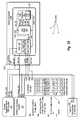
- FIG. 2Aschematically illustrates portions of an optical transceiver circuit in which a boot component controller is in boot mode in which the controller communicates with various components using two different two-wire interfaces;
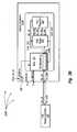
- FIG. 2Bschematically illustrates portions of the optical transceiver circuit in which the boot component is in passthrough mode in which the boot component permits communication to pass through between an external controller and the internal slave component;
- FIG. 3illustrates a circuit diagram of the core of FIGS. 2A and 2B in further detail
- FIG. 4schematically illustrates a sequential data structure of a frame that defines an FSB two-wire interface
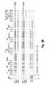
- FIG. 5Aillustrates an example frame in which the operation is to write or read using an extended field, and using Cyclic Redundancy Checking (CRC) and acknowledgements;
- CRCCyclic Redundancy Checking
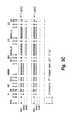
- FIG. 5Billustrates an example frame in which the operation is to write or read without using an extended field, and using CRC and acknowledgements
- FIG. 5Cillustrates an example frame in which the operation is to write or read without using an extended field, and without using CRC and acknowledgements.
- the principles of the present inventionrelate to a two-wire interface module that includes a first two-wire interface component configured to receive a first two-wire interface communication following a first two-wire interface protocol, and a second two-wire interface component configured to generate a second two-wire interface communication following a second two-wire interface protocol.
- the first and second two-wire interface communicationseach include a header portion and a payload portion.
- the second two-wire interface componentis further configured to use one or more of the data fields from the payload portion of the first two-wire interface communication in the header portion of the second two-wire interface communication. Accordingly, portions of the header portion of the second two-wire interface communication may be generated with minimal processing, by transplanting from one communication to another, despite the two communications following different two-wire interface protocols.
- FIG. 1illustrates an environment 100 that includes a two-wire interface module 101 communicates between several two-wire interface modules 120 and 130 .
- a “two-wire interface module”is an integrated circuit that is capable of communicating using a two-wire interface protocol.
- the environment 100may be a telecommunications system, an optical transceiver, or any other environment in which two-wire communications may be useful.
- the two wire interface module 110includes a first two-wire interface component 112 that is configured to receive a first two-wire interface communication 121 following a first two-wire interface protocol.
- the first communication 121is received from the two-wire interface module 120 .
- the communication 121includes a header portion 122 and a payload portion 123 .
- the payload portionincludes a number of data fields includes one or more data fields identified as element 124 in FIG. 1 .
- the two wire interface module 110also includes a logic component 111 may be configured to extract the one or more data fields 124 from the payload of the communication 121 , and provide the one or more data fields 111 to the second two-wire interface component 113 .
- the second two wire interface component 113then generates the second two-wire interface communication 131 by inserting the one or more data fields 124 in the header portion of the communication 131 .
- the communicationmay then be transmitted using the second two-wire interface protocol to the two-wire interface module 130 .
- the information from the payload of one communication following one two-wire interfacemay serve in the header portion of a different two-wire interface. This reduces the processing and hardware complexity associated with providing the information in the different two-wire interface.
- the first two-wire interface protocolmay be the I 2 C two-wire interface protocol
- the second two-wire interfacemay be the FSB two-wire interface protocol, and vice versa.
- FSBstands for “Finisar Serial Bus” and is a Finisar-proprietary two-wire interface protocol. More regarding the FSB two-wire interface is described below with respect to FIGS. 4 , 5 A, 5 B and 5 C.
- FIG. 1Having described the principles of the present invention with respect to FIG. 1 , a specific implementation will be described with respect to FIGS. 2A , 2 B and 3 . Those of ordinary skill in the art will recognize upon reviewing this description that the specific implementation described below represent just one of countless implementation in which the principles of the present invention may be useful.
- FIGS. 2A and 2Bschematically illustrate a telecommunications system 200 A and 200 B that includes an optical transceiver 210 A and 210 integrated circuit that includes a digital core component 213 .
- the digital core component 213includes a boot component 221 , an FSB slave component 225 and an FSB register array component 226 .
- the slave component 225 and the register array 226are labeled as FSB components because they may communicate using the FSB two-wire interface.
- the principles of the present inventionare not limited to any specific manner of communication within the optical transceiver integrated circuit.
- the boot component 221 of FIG. 2Arepresents an example of the two-wire interface module 101 of FIG. 1 .
- the FSB slave component 225 of FIG. 2Arepresents an example of the two-wire interface module 130 of FIG. 1 .
- the EEPROM 234 of FIG. 2Arepresents an example of the other two-wire interface modules 110 of FIG. 1 .
- the FSB slave component 225reads data from and writes data to specified address locations within the FSB register array component 226 in response to specific FSB commands received from or through the boot component 221 . Specifically, the FSB slave component 225 may generate signal mem_addr to address a location within the FSB register array 226 , signal wr_enable to enable a write operation, and signal wr_data to specify the data to be written. In addition, the FSB slave component may read signal rd_data to read data from the specified memory address.
- the FSB register array 226includes an XOR tree 227 which generates a parity_error signal if there is a parity error detected in the FSB register array. The structure and purpose of the XOR tree 227 will be described further below.
- FIG. 2Aillustrates a configuration 200 A in which there is no controller external to the optical transceiver 210 A. Instead, the on-chip boot component 221 serves as a controller. This configuration will be frequently referred to herein as the “internal controller configuration”. In particular, the boot component 221 operates while the optical transceiver integrated circuit is starting up. During startup, the boot component 221 coordinates the proper loading of appropriate instructions from an external EEPROM 234 into the FSB register array 226 . Once the startup process completes, the post-amplifier and the laser driver are then controlled based on the values within the FSB register array 226 .
- the boot component 221While booting in the internal controller configuration of FIG. 2A , the boot component 221 is active. Even in this active state, the boot component 221 may be temporarily disabled by asserting the signal frc_disable_boot signal high.
- the boot component 221communicates with the memory 234 using the conventional I 2 C two-wire interface.
- the boot control component 223 of the boot component 221causes the I 2 C master component 222 of the boot component 221 to communicate with the EEPROM memory 234 using the I 2 C-compliant clock, data, and write protect signals.
- the clock signalis represented in FIG. 2A by signal SCL from the EEPROM perspective and signal twi_clk from the boot component perspective.
- the data signalis represented by signal SDA from the EEPROM perspective and signal twi_data from the boot component perspective.
- the write disable signalis represented by signal WP from the EEPROM perspective and by signal boot_busy from the boot component 221 perspective.
- the I 2 C two-wire interface and these corresponding signalsare well-known to those of ordinary skill in the art.
- the boot component 221may communicate with and control the FSB slave component 225 using the FSB two-wire interface.
- the boot component 221may use the boot control component 223 to control the FSB master component 224 .
- the FSB master component 224provides an appropriate clock signal fsb_clk to the FSB slave component 225 and the FSB register array 226 .
- the FSB master component 224provides a data signal fsb_data to the FSB slave component 225 .
- the fsb_clk and fsb_data signalsare provided in conformity with the FSB two-wire interface described below with respect to FIGS. 4 , 5 A, 5 B and 5 C.
- the boot logic component 223is configured such that when the boot component 221 is starting up, the appropriate data is loaded from the EEPROM 234 into the FSB register array 226 .
- the values within the FSB register array 226then control important components of the optical transceiver include the laser driver and post-amplifier (not shown). As previously mentioned, doing so involves communication with the EEPROM 234 using one two-wire interface while communicating with other components (e.g., the FSB slave component 225 ) using a different two-wire interface.
- the I 2 C master component 222 , the boot logic component 223 , and the FSB master component 224 of FIG. 2Arepresent examples of the first two-wire interface component 112 , the logic component 111 , and the second two-wire interface component 113 of FIG. 1 .
- the internal controller configuration of FIG. 2Aalso illustrates several other external components.
- optional diagnostic mode FSB controller 231asserts signal frc_fsb_mode
- the signal frc_disable_boot signalis likewise asserted, thereby disabling the boot controller 221 .
- Thisallows the diagnostic mode FSB controller 231 to communicating straight through the boot component 221 and to the FSB slave component 225 using the FSB two-wire interface using clock signal fsb_clk and data signal fsb_data.
- the boot controller 221mirrors any signals received to the other side.
- the diagnostic mode FSB controller 231behaves as an FSB master component. Accordingly, the diagnostic mode FSB controller 231 may control the FSB slave component 225 to thereby cause appropriate diagnostics to be made on the FSB register array 226 .
- the EEPROM programming interface 232may likewise assert the frc_disable_boot signal to at least temporarily disable any boot operations.
- the EEPROM programming interface 232may then communicate with the EEPROM 234 using the SCL and SDA signals in accordance with the conventional I 2 C two-wire interface. By disabling the boot process during the EEPROM programming, the risk of contention on the clock signal SCL and data signal SDA is significantly reduced.
- An optional host interface to EEPROM 233may also be provided to allow a host computing system to interface with the EEPROM 234 .
- the optical transceiver 210 Ahas a mechanism for recovering from register array corruption even without the clock being initially on.
- each byte in the register array 226has a corresponding parity bit.
- the XOR tree 227includes an XOR sub-tree that logically XOR's each of the bits in the byte to generate an actual byte parity bit.
- the actual byte parity bitwill be high if the number of logical one's in the byte is odd, and low if the number of logical one's in the byte is even, regardless of whether or not the byte is corrupted.
- the actual byte parity bitis XOR'ed with an ideal byte parity bit stored for each byte.
- the ideal byte parity bitis high if the number of logical one's in the byte should be odd absent any corruption, and low if the number of logical one's in the byte should be even absent any corruption.
- the actual byte parity bitis logically XOR'ed with the ideal byte parity bit to generate a byte parity error bit.
- the byte parity error bitwill only be high if the corresponding byte has become corrupted.
- the various byte parity bitsmay be logically OR'ed (or XOR'ed) to generate the parity_error signal in FIG. 2A .
- the parity_error signalwill only be high if the FSB register array has experienced corruption.
- the boot control component 223asserts the en_boot_clk signal, which activates the oscillator 228 to thereby reinitiate the boot process. Rebooting should then initialize the register array to appropriate values to thereby allow normal operation to proceed. Once again, after the boot process, the boot clock may be shut off to reduce noise.
- the boot controller 221permits the internal controller configuration of FIG. 2A in which the controller, the post-amplifier, and the laser driver are all on the same optical transceiver integrated circuit. However, the boot controller 221 may also provide flexibility to have an external controller.
- FIG. 2Bshows such a configuration 200 B in which the FSB master controller 240 communicates directly through the boot component 221 to the FSB slave component 225 using clock signal fsb_clk and data signal fsb_data that conform to the FSB two-wire interface. In this case, the enable_boot signal is low thereby rendering the boot clock and the boot controller inactive. Furthermore, the frc_disable signal is low.
- the configuration of FIG. 2Bmay also be referred to herein as the “external controller configuration”.
- the FSB master component 240may operate to load, monitor, and update the FSB register array 226 via the FSB slave component 225 .
- the optical transceiver integrated circuit 210 A of FIG. 2Amay be physically structured identically to the optical transceiver integrated circuit 210 B of FIG. 2B .
- the differenceis in the value of the enable_boot signal and possibly the frc_disable_boot signal.
- the enable_boot signalmay be the same in both FIGS. 2A and 2B , with the signal frc_disable_boot representing an override signal that enables the override configuration illustrated in FIG. 2B .
- the optical receiver 210is flexible enough to accommodate both the internal controller configuration and the external controller configuration. Furthermore, this flexibility may be obtained by simply asserting appropriate configuration signals enable_boot and frc_disable_boot to the integrated circuit.
- FIG. 3illustrates a configuration 300 of the core component 213 in further detail.
- the I 2 C master component 222 , the boot control component 223 and the FSB master component 224are collectively illustrated in FIG. 3 as boot state machine 310 .
- the boot state machine 310In the internal controller configuration, when the frc_disable_boot signal is low and the enable_boot signal is high, the boot state machine has access to the boot clock signal boot_clk.
- the boot state machine 310operates as an FSB master component for the FSB slave component 225 .
- the boot state machine 310pulls signal fsb_slave_mode_sel low. This causes the upper input terminal (marked “0”) of each of the multiplexers 311 through 316 to by coupled to its corresponding output terminal. The operation during this internal controller configuration will now be described in further detail with respect to FIG. 3 .
- the boot state machine 310generates a clock signal boot_fsb_clk (out) that is derived from the boot clock signal boot_clk. This clock signal boot_fsb_clk (out) is then provided through the multiplexer 311 to become the FSB clock signal fsb_clk.
- the boot state machine 310also may generate a data signal in accordance with the FSB two-wire interface and timed in accordance with the FSB clock signal. This data signal is represented by boot_fsb_do (out) passing through the multiplexer 314 to become signal fsb_di provided to the FSB slave component 225 .
- the FSB slave component 225may transmit data back to the state machine using signal fsb_do and using output enable signal fsb_do_oe. Accordingly, the boot state machine 310 is fully capable of acting as an FSB master component for the FSB slave component 225 using the configuration illustrated in FIG. 3 .
- the boot state machine 310is also capable of communicating with the EEPROM using the I 2 C two-wire interface. Specifically, a logical zero is asserted through the upper input terminal of the multiplexer 312 as signal TWI_CO.
- a clock signal boot_scl generated by the boot state machine 310serves as the clock signal for the I 2 C interface. If the clock signal boot_scl is high, the clock signal is inverted to low through inverter 321 to provide a low signal to the upper input terminal of multiplexer 313 . This low signal is provided to driver 322 thereby isolating low signal TWI_CO from the output terminal of the driver 322 .
- the signal twi_clk(the actual clock signal on the clock wire to the EEPROM) is permitted to pull high through pull-up resistor 323 .
- the clock signal boot_sclis low, the clock signal is inverted to high through inverter 321 to provide a high signal to the upper input of multiplexer 313 .
- This high signalis provided to driver 322 thereby causing the driver to pass signal TWI_CO (which is low) as the clock signal twi_clk provided to the EEPROM.
- TWI_COwhich is low
- the I 2 C clock signal twi_clk provided to the EEPROMfollows the I 2 C clock signal boot_scl generated by the boot state machine 310 .
- a logical zerois asserted through the upper input terminal of the multiplexer 315 as signal TWI_DO.
- a data signal boot_sda generated by the boot state machine 310serves as the data signal generated by the boot component 221 for the I 2 C interface with the EEPROM. If the data signal boot_sda is high, the data signal is inverted to low through inverter 324 to provide a low signal to the upper input of multiplexer 316 . This low signal is provided to driver 325 thereby isolating low signal TWI_DO from the output terminal of the driver 325 .
- the signal twi_data(the actual data signal on the data wire to the EEPROM) is permitted to pull high through pull-up resistor 326 . If the data signal boot_sda is low, the data signal is inverted to high through inverter 324 to provide a high signal to the upper input of multiplexer 316 . This high signal is provided to driver 325 thereby causing the driver to pass signal TWI_DO (which is low) as the data signal twi_data provided to the EEPROM. This emulates an open-drain driver while still maintaining the capability to directly drive the interface as desired. Accordingly, the I 2 C data signal twi_data provided to the EEPROM follows the I 2 C data signal boot_data generated by the boot state machine 310 . In the other direction, the boot state machine 310 may also monitor data on the I 2 C data wire. The signal twi_data is provided through the driver 327 as the I 2 C data input signal boot_sda to the boot state machine 310 .
- the boot state machine 310serves as an FSB master for the FSB slave component 225 , and as an I 2 C master for the external EEPROM.
- the data state machinepermits off-chip components such as a controller to pass through communications through the boot component 221 directly to the FSB slave component 225 . This serves the external controller configuration model of FIG. 2B .
- the boot state machineIn the external controller configuration mode, the boot state machine asserts the fsb_slave_mode_sel signal high. This couples the lower input terminal of the multiplexers 311 through 316 to their respective output terminals. Accordingly, the clock signal twi_clk generated by the off_chip controller passes directly through the driver 328 and through the multiplexer 311 to the FSB slave component 225 and FSB register array 226 . The driver 322 is off and thus the boot state machine 310 does not communicate any clock signals.
- the data signals twi_data generated by the external controllerpasses through the driver 327 , through the multiplexer 314 , and to the FSB slave component 225 . If the FSB slave component 225 generates a high output enable signal fsb_do_eo, the driver 325 is on, and the data signal fsb_do generated by the FSB slave component 225 is provided through the multiplexer 315 and through the driver 325 to generate the data signal twi_data. Accordingly, in this configuration, the external controller communicates directly with the FSB slave component.
- FIG. 4illustrates a schematic diagram of a data structure 400 of a frame of an FSB two-wire interface mentioned briefly above with respect to FIGS. 2A , 2 B and 3 .
- the frame 400includes a preamble field 401 , a frame start field 402 , an operation field 403 , a device identifier field 404 , an optional extended field 405 , a basic address field 406 , a first bus turnaround field 407 , and optional bus hold field 408 , a data field 409 , an optional Cyclic Redundancy Checking (CRC) field 410 , a second bus turnaround field 411 , an optional acknowledgement field 412 , an optional error status field 413 , and a frame end field 414 .
- CRCCyclic Redundancy Checking
- the frame 400is designed so that within any component's turn for control of the data wire, there is a guaranteed zero interspersed more frequently than the length of the preamble.
- Any of the data fields illustrated in FIG. 4may serve as the one or more data fields 124 transplanted from the data field portion 123 of the communication 121 to the header field 132 of the communication 131 .
- the CRC field 410in particular is helpful in this respect as it allows the first two-wire interface protocol used in communicating between the two-wire interface modules 120 and 110 to provide security for the second two-wire interface protocol used in communicating between the two-wire interface modules 110 and 130 .
- the bus turnaround fieldsallow for optional transfer of data wire control between the FSB master component and the FSB slave component. Accordingly, the FSB master component may be providing some of the frame, while the FSB slave component may be providing other portions of the frame. Note that while a specific ordering of fields is shown in FIG. 4 , there is considerable flexibility as to the ordering of the fields without adversely affecting the functionality of the frame 400 as will be apparent to those of ordinary skill in the art after having reviewed this description.
- FIGS. 5A , 5 B and 5 Cshow specific embodiments of the frame 400 . Some of the optional fields are included or excluded depending on the operation being performed.
- FIG. 5Aillustrates an example frame in which the operation is to write or read using an extended field, and using Cyclic Redundancy Checking (CRC) and acknowledgements.
- FIG. 5Billustrates an example frame in which the operation is to write or read without using an extended field, and using CRC and acknowledgements.
- FIG. 5Cillustrates an example frame in which the operation is to write or read without using an extended field, and without using CRC and acknowledgements.
- FIG. 5Aillustrates the most inclusive frame example, the various fields of the frame will be described in most detail with respect to FIG. 5A .
- the frame of FIG. 3Aincludes 75 bits corresponding to bits 74 : 0 , regardless of whether the operation is a read operation as specified in line 501 A or a write operation as specified in line 504 A.
- Line 502 Aillustrates an asterix at time increments when the FSB master component is in control of the data wire during a read operation, and otherwise contains a period.
- “MOE” at the beginning of the linestands for “Master data Output Enable”.
- Line 303 Aillustrates an asterix at time increments when the FSB slave component is in control of the data wire during a read operation, and otherwise contains a period.
- “SOE” at the beginning of the linestands for “slave data Output Enable”.
- line 505 Aillustrates an asterix at time increments when the FSB master component is in control of the data wire during a write operation, and otherwise contains a period.
- line 506 Aillustrates an asterix at time increments when the FSB slave component is in control of the data wire during a write operation, and otherwise contains a period.
- Lines 307 A and 308 Awill be explained further below.
- the framebegins with a preamble as represented in FIG. 5A by the 15 bits 74 : 60 .
- This preambleis an example of the preamble field 401 of FIG. 4 .
- the data wire 132is left in a high impedance state. Absent any assertion on the data wire by FSB master component or any of the FSB slave component(s), the data wire is held to a logical one by a pull-up resistor (see resistor 326 of FIG. 3 ).
- the FSB master componentdetermines that a communication is to be made with FSB slave component, the FSB master component generates a clock signal on the clock wire. At the same time, each clock cycle, the FSB master component monitors the data wire for fifteen consecutive ones.
- the high impedance data wiredoes allow for proper assertion of data on the data wire despite the presence of the pull-up resistor.
- the data wireshould carry a logical one if none of the FSB slave components is transmitting the remainder of a prior frame on the data wire.
- the FSB master componentmay be asserting a logical one on the data wire during at least some of the preamble, then the data wire should still be carrying the logical one during the preamble phase assuming that none of the FSB slave components is transmitting on the data wire at that time.
- the frameis designed such that neither a FSB master nor a FSB slave transmits more than fifteen consecutive logical ones in a row when transmitting non-preamble portions of the frame.
- the FSB master componentdetects a logical zero on the data wire while monitoring the data wire during the preamble phase of the frame, then a FSB slave component is likely communicating on the data wire. Whether or not logical zeros are detected, the FSB master component will wait until there are fifteen cycles of logical ones on the data wire before continuing with the frame. Due to the interspersed guaranteed zeros within the frame design, it is then that the FSB master component may safely transmit on the data wire with little risk that one of the FSB slave component(s) is also communicating on the data wire.
- synchronizationis reacquired as the FSB master component waits for the FSB slave component to complete its use of the data wire before proceeding.
- the FSB slave componentalso monitors the data wire for fifteen consecutive ones. Accordingly, when the FSB slave component encounters fifteen consecutive ones, the FSB slave component awaits the rest of the frame. Accordingly, since the FSB slave component is not using the data wire at the time of the preamble regardless of whether the FSB slave component had previously lost synchronization with the FSB master component, the FSB slave component should be listening for the preamble at the preamble phase of the frame. Accordingly, the FSB slave component reacquires synchronization with the FSB master component.
- the preambleis significantly shortened while further retaining error recovery from loss of synchronization. Furthermore, since the data wire is biased high due to the pull-up resistor, the FSB master component need not assert any data on the data wire during the preamble phase, thereby reducing power requirements.
- the FSB master componentasserts a logical one on the data wire as represented by bit 59 . This turns on the output enable for the FSB master component, and maintains the data wire at the logical one for one more cycle.
- the FSB master componentthen transmits two start of frame bits 58 : 57 which are guaranteed logical zeros. These start of frame bits are an example of the start of frame field 402 of FIG. 4 .
- the FSB slave component(s)are listening for these logical zeros. When they arrive, the FSB slave component(s) understand that the two logical zeros correspond to the start of the rest of the frame, thereby attaining synchronization. Two logical zeros are provided in order to provide sufficient statistical probability that the two logical zeros do indeed represent the start of a frame.
- the FSB master componentthen transmits three operation code bits 56 : 54 .
- These operation code bitsare an example of the operation field 403 of FIG. 4 .
- the three operation code bitswould normally permit eight unique operations to be identified. However, in order to guarantee at least one logical zero in this operation code, the number of operations represented by the three bits is six, with the other two permutations of the operation code being reserved. In the illustrated example, bit sequences 011 and 111 are reserved.
- operations bits 000mean a write operation without using an extended field (explained further below), but with CRC checking and acknowledgements.
- a frame for this operationis shown in line 504 B of FIG. 5B (see bits 47 : 45 of line 504 B).
- Operation bits 001mean a write operation using an extended field, and with CRC checking and acknowledgments.
- a frame for this operationis shown in line 504 A of FIG. 5A (see bits 56 : 54 of line 504 A).
- Operation bits 010mean a write operation without using an extended field, and without CRC checking and acknowledgments.
- a frame for this operationis shown in line 504 C of FIG. 5C (see bits 35 : 33 of line 504 C).
- Operations bits 100mean a read operation without using an extended field, but with CRC checking and acknowledgements.
- a frame for this operationis shown in line 501 B of FIG. 5B (see bits 47 : 45 of line 501 B).
- Operation bits 101mean a read operation using an extended field, and with CRC checking and acknowledgments. A frame for this operation is shown in line 501 A of FIG. 5A (see bits 56 : 54 of line 501 A).
- Operation bits 110mean a read operation without using an extended field, and without CRC checking and acknowledgments.
- a frame for this operationis shown in line 501 C of FIG. 5C (see bits 35 : 33 of line 501 C).
- the FSB master componentcontrols which frame structure is to be used by controlling the operation code.
- the FSB slave componentUpon reading the operation code, the FSB slave component is configured to expect the frame structure corresponding to the operation code.
- the FSB master componentmay dynamically adjust the frame structure as needed. In times when bandwidth is more of a concern, the shorter and less reliable frame structure (e.g., FIG. 5C ) may be used. In times when reliability is more of a concern, the longer and more reliable frames structure (e.g., FIGS. 5A and 5B ) may be used. When further bits are needed for any reason, the frame with the extended field (e.g., FIG. 5A ) may be used. When these further bits are not needed, the frames without the extended field (e.g., FIGS. 5B and 5C ) may be used.
- the FSB master componenttransmits the operation code (i.e., bits 56 : 54 )
- the FSB master componenttransmits a three bit device identifier corresponding to bits 53 : 51 .
- These device identifier bitsare an example of the device identifier field 404 of FIG. 4 .
- the device identifieridentifies which FSB slave component of the FSB slave component(s) that the FSB master component is to communicate with. Since three bits are used for the device identifier in this embodiment, there may be up to eight FSB slave components in this embodiment (or seven FSB slave components if the FSB master component is to also have an address for self-diagnostic purposes).
- each of the FSB slave component(s)was monitoring the communications over the data wire.
- the FSB slave componentmay identify itself as corresponding to the device identifier.
- the other FSB slave componentsif any, may ignore the rest of the frame. Even though the other FSB slave components ignore the rest of the frame, the other FSB slave components may immediately continue monitoring the data wire for another preamble indicative of another frame being transmitted. Alternatively, the other FSB slave component may initiate such monitoring after clock signals are once again asserted on the clock wire indicating that the next frame is about to begin.
- the FSB master componentAfter the FSB master component asserts the device identifier bits 53 : 51 on the data wire, the FSB master component asserts eight bits 50 : 43 that correspond to an extended field. These extended bits are an example of the extended field 405 of FIG. 4 . In the case of FIG. 5A , the operation code causes the FSB slave component to expect these extended bits. The FSB master component then transmits a guaranteed logical zero as bit 42 thereby ensuring that fifteen consecutive logical ones on the data wire means that a frame is in the preamble phase to thereby support the above-described synchronization recovery mechanism.
- the extended fieldmay include any extended bits that are useful so long as the meaning of the bits is commonly recognized by both communicating components.
- some or all of the extended fieldmay represent an extended address for use when communicating with FSB slave components having larger address spaces.
- some or all of the extended fieldmay represent an extended operation code where further operation types are desired.
- the FSB master componentthen asserts eight bits 41 : 34 that correspond to the basic address. These eight bits 41 : 34 are an example of the basic address field 406 of FIG. 4 . If all of the extended field represents an extended address, the FSB slave component may use all of the sixteen bits 50 : 43 and 41 : 34 to properly identify the address space that applies to the operation.
- the next bit 33 in the frameis a first turnaround bit and represents an example of the first turnaround field 407 of FIG. 4 .
- the turnaround bitsare somewhat unique in that they allow for optional exchange of control of the data wire between the FSB master component and the FSB slave component.
- the first turnaround bit 33is a logical zero, indicating that control is to stay for the time being with the FSB master component. Accordingly, referring to line 505 A of FIG. 5A , the FSB master component retains control of the data wire through the turnaround bit 33 ; and referring to line 506 A of FIG. 5A , the FSB slave component does not gain control of the data wire through the turnaround bit 33 . This retaining of control is appropriate since the FSB master component is the one that is providing that data that is the subject of a write operation initiated by the FSB master component.
- the first turnaround bit 33is a high-z, meaning that the data wire is permitted to float at its high impedance state in which none of the FSB master component or FSB slave component is actively asserting bits on the data wire.
- This transfer of controlis appropriate since the FSB slave component is the one that is providing that data that is the subject of a read operation initiated by the FSB master component.
- the FSB slave componentIn the case of a read operation, the FSB slave component then has the opportunity to pause the frame in cases in which the FSB slave component is not ready to continue at this stage.
- the FSB slave componentasserts the bus hold bit 32 to a logical zero if it is not ready to continue.
- the FSB slave componentWhen ready to continue, the FSB slave component asserts a logical one if it is ready to proceed thereby given the FSB master component notice that the FSB slave component is ready to continue. This provides the FSB slave component with an option to pause the frame when the FSB slave component is not ready to continue for the time being. An additional pausing option available to the FSB slave component is described below with respect to the acknowledgement bit.
- the bus hold bit 32In the case of a write operation, the bus hold bit 32 is a guaranteed logical one.
- the bus hold bit 32is an example of the bus hold field 408 of FIG. 4 .
- the FSB slave componenttransmits the eight most significant bits followed by a guaranteed zero bit.
- the FSB master componenttransmits the eight most significant bits followed by the guaranteed zero bit. In either case, the eight most significant bits are represented by bits 31 : 24 , and the following guaranteed zero bit is represented by bit 23 .
- the FSB slave componenttransmits the eight least significant bits followed by another guaranteed zero bit.
- the FSB master componenttransmits the eight least significant bits followed by the other guaranteed zero bit.
- the eight least significant bitsare represented by bits 22 : 15
- the other guaranteed zero bitis represented by bit 14 .
- the combination of the data bits 31 : 24 and 22 : 15are an example of the data field 409 of FIG. 4 .
- the FSB slave componenttransmits eight bits of Cyclic Redundancy Checking (CRC) data corresponding to bits 13 : 06 .
- the CRC bitsare one example of the CRC field 410 of FIG. 4 .
- both the FSB master component and the FSB slave componentcalculate CRC data as shown in line 507 A.
- the FSB master componentWhen the FSB master component receives the CRC bits 13 : 06 back from the FSB slave component, the FSB master component then compares the CRC information generated by both the FSB master component and the FSB slave component as represented by line 508 A. If there is a mismatch, then there has likely been an error in transmission, and the FSB master component may begin the frame again after the current frame is ended.
- the FSB master componenttransmits the CRC bits 13 : 06 .
- both the FSB master component and the FSB slave componentcalculate their CRC data.
- the FSB slave componentreceives the CRC bits 13 : 06 from the FSB master component, the FSB slave component then compares the CRC information generated by both the FSB master component and the FSB slave component. If there is a mismatch, then there has likely been an error in transmission, and the FSB master component may begin the frame again after the current frame is ended after the FSB master component has been notified of the error.
- an erroneous write operationmay have catastrophic (or at least harmful) effects.
- the erroneous write operationwas for setting a laser bias current, the laser strength could be too strong such that signal distortion occurs. Accordingly, reliable communications is important in such circumstances.
- the FSB slave componentmay elect to suppress a write operation when such an error is detected.
- This second turnaround bit 05is an example of the second turnaround field 411 of FIG. 4 .
- This turnaround operationallows control of the data wire to be given to the FSB slave component if control is not there already. This allows the FSB slave component to give reliability information back to the FSB master component.
- control of the data wirehas already been passed to the FSB slave component using the first turnaround bit. Accordingly, this second turnaround bit is a logical zero indicating no change in control of the data wire.
- control of the data wirewas not previously given to the FSB slave component using the first turnaround bit. Accordingly, the data wire is allowed to float at its high impedance state indicating a transfer of control of the data wire to the FSB slave component. Accordingly, after the second turnaround bit 05 , the FSB slave component has control of the data wire regardless of whether the operation is a read operation or a write operation.
- the FSB slave componentAfter the second turnaround bit 05 , the FSB slave component asserts an acknowledgment bit 04 , which is an example of the acknowledgement field 412 of FIG. 4 .
- This acknowledgement bitmay represent whether or not the operation was successful. In this case, a logical one means successful completion of the operation.
- the FSB slave componentHad the FSB slave component been too busy to respond to the FSB master component, the FSB slave component may assert a logical zero for the acknowledgement bit 04 , thereby forcing the FSB master component to reinitiate the frame. Accordingly, the acknowledgment bit 03 , and the bit hold bit 32 provide a way for the FSB slave component to address the situation where it cannot respond to the request.
- the FSB slave componentthen asserts a guaranteed zero bit 03 , followed by an error bit 02 , which is an example of the error field 413 of FIG. 4 .
- the error fieldmay indicate whether or not there was an error in CRC checking and/or a violation of the protocol (e.g., a logical one is detected where a logical zero should occur).
- the FSB master componentwill already be in possession of CRC data sufficient to make this determination.
- the FSB slave componentis the one that made the comparison of CRC data. Accordingly, it is at this time that the FSB slave component notifies the FSB master component of any mismatch in CRC data. A mismatch would result in the FSB master component reinitiating the frame.
- the presence of CRC and acknowledgment information in the frameallows for more reliable communication between the FSB master component and the FSB slave component(s).
- the FSB slave componentthen asserts two end of frame bits 01 : 00 , which indicates the end of the frame.
- the first bit 01is a logical one, which forces the data bus immediately to a logical one.
- the data busis allowed to float at its high impedance state, ready for the next frame to begin. If the first bit 01 were a logical zero, it may take some time for the pull-up resistor to pull the data wire up to a voltage level that could be interpreted as a logical one. Accordingly, the setting of the first bit 01 at a logical one means that the next frame may begin sooner, thereby improving performance.
- FIG. 5Billustrates an example frame in which the operation is to write or read without using an extended field, and using CRC and acknowledgements.
- the frame of off FIG. 5Bis similar to that described above with respect to FIG. 5A , except that the operation is to write or read without using the extended field. Accordingly, bits 50 : 42 of FIG. 5A are absent from FIG. 5B and the bits are renumbered accordingly.
- FIG. 5Cillustrates an example frame in which the operation is to write or read without using an extended field, and without using CRC and acknowledgements.
- the frame of FIG. 5Cis similar to that described above with respect to FIG. 5A , except that the operation is to write or read without using the extended field. Accordingly, bits 50 : 42 of FIG. 5A are absent from FIG. 5B . Furthermore, there is no reliability information within the frame. Hence, bits 13 : 02 of FIG. 5A are absence from FIG. 5C . The absence from FIG. 5C of bits that are present in FIG. 5A warrants the renumber of the remaining bits in FIG. 5C .
- embodiments of the inventionmay be implemented in various ways.
- some embodiments of the PA/LDare implemented in Small Form Factor Pluggable (“SFP”) bi-directional transceiver modules.
- SFPSmall Form Factor Pluggable
- Such transceiver modulesare configured for GigE and/or FC compliance.
- Exemplarily, such transceiver modulesare capable of transmitting and/or receiving at a wavelength of about 850 nm.
- these transceiver modulescan operate over a wide range of temperatures.
- some of such transceiver modulesare effective over a temperature range of about 80° C., such as from about ⁇ 10° C. to about +70° C.
- the principles of the present inventionmay be implemented in laser transmitter/receivers of any form factor such as XFP, SFP and SFF, without restriction.
Landscapes
- Engineering & Computer Science (AREA)
- Computer Networks & Wireless Communication (AREA)
- Signal Processing (AREA)
- Information Transfer Systems (AREA)
Abstract
Description
Claims (29)
Priority Applications (1)
| Application Number | Priority Date | Filing Date | Title |
|---|---|---|---|
| US11/074,608US8225024B2 (en) | 2004-03-05 | 2005-03-07 | Use of a first two-wire interface communication to support the construction of a second two-wire interface communication |
Applications Claiming Priority (2)
| Application Number | Priority Date | Filing Date | Title |
|---|---|---|---|
| US55044404P | 2004-03-05 | 2004-03-05 | |
| US11/074,608US8225024B2 (en) | 2004-03-05 | 2005-03-07 | Use of a first two-wire interface communication to support the construction of a second two-wire interface communication |
Publications (2)
| Publication Number | Publication Date |
|---|---|
| US20050237991A1 US20050237991A1 (en) | 2005-10-27 |
| US8225024B2true US8225024B2 (en) | 2012-07-17 |
Family
ID=35136329
Family Applications (1)
| Application Number | Title | Priority Date | Filing Date |
|---|---|---|---|
| US11/074,608Active2026-07-05US8225024B2 (en) | 2004-03-05 | 2005-03-07 | Use of a first two-wire interface communication to support the construction of a second two-wire interface communication |
Country Status (1)
| Country | Link |
|---|---|
| US (1) | US8225024B2 (en) |
Cited By (17)
| Publication number | Priority date | Publication date | Assignee | Title |
|---|---|---|---|---|
| US9038141B2 (en) | 2011-12-07 | 2015-05-19 | Adc Telecommunications, Inc. | Systems and methods for using active optical cable segments |
| US9207417B2 (en) | 2012-06-25 | 2015-12-08 | Adc Telecommunications, Inc. | Physical layer management for an active optical module |
| US9380874B2 (en) | 2012-07-11 | 2016-07-05 | Commscope Technologies Llc | Cable including a secure physical layer management (PLM) whereby an aggregation point can be associated with a plurality of inputs |
| US9473361B2 (en) | 2012-07-11 | 2016-10-18 | Commscope Technologies Llc | Physical layer management at a wall plate device |
| US9544058B2 (en) | 2013-09-24 | 2017-01-10 | Commscope Technologies Llc | Pluggable active optical module with managed connectivity support and simulated memory table |
| US10026247B2 (en) | 2015-07-06 | 2018-07-17 | Hanchett Entry Systems, Inc. | Request to exit two-wire control module |
| US10188890B2 (en) | 2013-12-26 | 2019-01-29 | Icon Health & Fitness, Inc. | Magnetic resistance mechanism in a cable machine |
| US10220259B2 (en) | 2012-01-05 | 2019-03-05 | Icon Health & Fitness, Inc. | System and method for controlling an exercise device |
| US10226396B2 (en) | 2014-06-20 | 2019-03-12 | Icon Health & Fitness, Inc. | Post workout massage device |
| US10272317B2 (en) | 2016-03-18 | 2019-04-30 | Icon Health & Fitness, Inc. | Lighted pace feature in a treadmill |
| US10279212B2 (en) | 2013-03-14 | 2019-05-07 | Icon Health & Fitness, Inc. | Strength training apparatus with flywheel and related methods |
| US10391361B2 (en) | 2015-02-27 | 2019-08-27 | Icon Health & Fitness, Inc. | Simulating real-world terrain on an exercise device |
| US10426989B2 (en) | 2014-06-09 | 2019-10-01 | Icon Health & Fitness, Inc. | Cable system incorporated into a treadmill |
| US10433612B2 (en) | 2014-03-10 | 2019-10-08 | Icon Health & Fitness, Inc. | Pressure sensor to quantify work |
| US10493349B2 (en) | 2016-03-18 | 2019-12-03 | Icon Health & Fitness, Inc. | Display on exercise device |
| US10625137B2 (en) | 2016-03-18 | 2020-04-21 | Icon Health & Fitness, Inc. | Coordinated displays in an exercise device |
| US10671705B2 (en) | 2016-09-28 | 2020-06-02 | Icon Health & Fitness, Inc. | Customizing recipe recommendations |
Families Citing this family (4)
| Publication number | Priority date | Publication date | Assignee | Title |
|---|---|---|---|---|
| US20080240103A1 (en)* | 2007-03-30 | 2008-10-02 | Andreas Schmidt | Three-port ethernet switch with external buffer |
| US9148286B2 (en) | 2007-10-15 | 2015-09-29 | Finisar Corporation | Protecting against counterfeit electronic devices |
| US20090240945A1 (en)* | 2007-11-02 | 2009-09-24 | Finisar Corporation | Anticounterfeiting means for optical communication components |
| US11907149B2 (en)* | 2020-12-09 | 2024-02-20 | Qualcomm Incorporated | Sideband signaling in universal serial bus (USB) type-C communication links |
Citations (73)
| Publication number | Priority date | Publication date | Assignee | Title |
|---|---|---|---|---|
| US4409592A (en)* | 1981-04-20 | 1983-10-11 | Hunt V Bruce | Multipoint packet data communication system using random access and collision detection techniques |
| US4495572A (en) | 1982-02-08 | 1985-01-22 | Zeda Computers International Limited | Computer intercommunication system |
| US4564838A (en) | 1982-03-29 | 1986-01-14 | Ncr Corporation | Data communication network and method of communication |
| US4642630A (en) | 1982-12-28 | 1987-02-10 | At&T Bell Laboratories | Method and apparatus for bus contention resolution |
| US4689740A (en) | 1980-10-31 | 1987-08-25 | U.S. Philips Corporation | Two-wire bus-system comprising a clock wire and a data wire for interconnecting a number of stations |
| US4706082A (en) | 1986-02-24 | 1987-11-10 | Chrysler Motors Corporation | Serial data bus for intermodule data communications |
| US4713808A (en)* | 1985-11-27 | 1987-12-15 | A T & E Corporation | Watch pager system and communication protocol |
| FR2695782A1 (en)* | 1992-09-15 | 1994-03-18 | Experdata | Data transmission between networks with different protocols - having first frame with data fields and integrity check field for data fields, and converting bit by bit to second field |
| US5367695A (en)* | 1991-09-27 | 1994-11-22 | Sun Microsystems, Inc. | Bus-to-bus interface for preventing data incoherence in a multiple processor computer system |
| US5410542A (en) | 1993-03-01 | 1995-04-25 | Diaogic Corporation | Signal computing bus |
| EP0705012A2 (en)* | 1994-09-20 | 1996-04-03 | AT&T Corp. | Computer network gateway |
| US5559502A (en) | 1993-01-14 | 1996-09-24 | Schutte; Herman | Two-wire bus system comprising a clock wire and a data wire for interconnecting a number of stations and allowing both long-format and short-format slave addresses |
| US5632016A (en)* | 1994-09-27 | 1997-05-20 | International Business Machines Corporation | System for reformatting a response packet with speed code from a source packet using DMA engine to retrieve count field and address from source packet |
| US5675617A (en) | 1994-10-05 | 1997-10-07 | Motorola, Inc. | Synchronous protocol encoding and decoding method |
| US5935224A (en) | 1997-04-24 | 1999-08-10 | Microsoft Corporation | Method and apparatus for adaptively coupling an external peripheral device to either a universal serial bus port on a computer or hub or a game port on a computer |
| US5946462A (en) | 1996-10-08 | 1999-08-31 | Advanced Micro Devices, Inc. | Station management circuit |
| US6065087A (en)* | 1998-05-21 | 2000-05-16 | Hewlett-Packard Company | Architecture for a high-performance network/bus multiplexer interconnecting a network and a bus that transport data using multiple protocols |
| US6081523A (en) | 1997-12-05 | 2000-06-27 | Advanced Micro Devices, Inc. | Arrangement for transmitting packet data segments from a media access controller across multiple physical links |
| US6085258A (en) | 1996-08-12 | 2000-07-04 | Lsi Logic Corporation | State machine for selectively performing an operation on a single or a plurality of registers depending upon the register address specified in a packet |
| US6115429A (en) | 1995-08-04 | 2000-09-05 | Huang; Shih-Wei | Data receiving method for receiving data through predetermined clear zones of a powerline |
| US6185620B1 (en)* | 1998-04-03 | 2001-02-06 | Lsi Logic Corporation | Single chip protocol engine and data formatter apparatus for off chip host memory to local memory transfer and conversion |
| US6215816B1 (en) | 1997-03-04 | 2001-04-10 | Texas Instruments Incorporated | Physical layer interface device |
| US6350063B1 (en)* | 1999-12-13 | 2002-02-26 | Stratos Lightwave, Inc. | Pluggable optical transceiver module having a high speed serial data connector (HSSDC) |
| US20020029233A1 (en) | 2000-09-05 | 2002-03-07 | Fumihide Kitamura | Bit string detecting circuit |
| US20020045519A1 (en) | 1999-07-08 | 2002-04-18 | Watterson Scott R. | Systems and methods for enabling two-way communication between one or more exercise devices and computer devices and for enabling users of the one or more exercise devices to competitively exercise |
| US6385669B1 (en)* | 1999-05-11 | 2002-05-07 | 3Com Corporation | Method and apparatus for the detection of the presence of a device on a high speed digital data bus |
| US20020073257A1 (en)* | 2000-12-07 | 2002-06-13 | Ibm Corporation | Transferring foreign protocols across a system area network |
| US20020087751A1 (en)* | 1999-03-04 | 2002-07-04 | Advanced Micro Devices, Inc. | Switch based scalable preformance storage architecture |
| US6463499B1 (en)* | 1999-10-14 | 2002-10-08 | Hewlett-Packard Company | Data bus cable having SCSI and IIC bus functionality and process for using the same |
| US20020149821A1 (en) | 2001-02-05 | 2002-10-17 | Aronson Lewis B. | Integrated memory mapped controller circuit for fiber optics transceiver |
| US20020181415A1 (en)* | 2001-04-24 | 2002-12-05 | Gerry West | System and method for communicating information from a computerized distributor to portable computing devices |
| US20020184385A1 (en)* | 2001-04-24 | 2002-12-05 | Saul Kato | Apparatus and method for communicating information to portable computing devices |
| US20030018839A1 (en)* | 2000-03-16 | 2003-01-23 | Seiko Epson Corporation | Data transfer control device and electronic equipment |
| US6512617B1 (en)* | 1998-02-03 | 2003-01-28 | Applied Micro Circuits Corporation | Methods and systems for control and calibration of VCSEL-based optical transceivers |
| US20030025587A1 (en) | 2001-07-10 | 2003-02-06 | Whitney Stephen J. | Electrostatic discharge multifunction resistor |
| US20030074488A1 (en)* | 2001-10-17 | 2003-04-17 | Griego David A. | Method and apparatus for communicating between modules |
| US20030113118A1 (en)* | 2001-11-28 | 2003-06-19 | Meir Bartur | Smart single fiber optic transceiver |
| US6643843B1 (en) | 1999-11-23 | 2003-11-04 | Ellenby Technologies Inc. | Methods and apparatus for optical communication update of program memory in embedded systems |
| US6647528B1 (en)* | 2000-11-02 | 2003-11-11 | Computer Network Technology Corporation | Fiber channel CRC for internal error checking on a switching platform |
| US20030229748A1 (en) | 2002-06-06 | 2003-12-11 | James Brewer | Method and system for supporting multiple bus protocols on a set of wirelines |
| US20040028412A1 (en) | 2002-08-09 | 2004-02-12 | Tim Murphy | System and method for multiple bit optical data transmission in memory systems |
| US20040059852A1 (en)* | 2002-09-24 | 2004-03-25 | Weiyun Sun | System and method of mastering a serial bus |
| US6715094B2 (en)* | 2000-12-20 | 2004-03-30 | Intel Corporation | Mult-mode I/O interface for synchronizing selected control patterns into control clock domain to obtain interface control signals to be transmitted to I/O buffers |
| US6738856B1 (en)* | 1999-01-19 | 2004-05-18 | Sequel Imaging, Inc | External display peripheral for coupling to a universal serial bus port or hub on a computer |
| US20040136720A1 (en) | 2003-01-15 | 2004-07-15 | Mahowald Peter H. | Task prioritization in firmware controlled optical transceiver |
| US20040139244A1 (en)* | 2003-01-09 | 2004-07-15 | International Business Machines Corporation | Method, system, and program for processing a packet including I/O commands and data |
| US20040136722A1 (en) | 2003-01-15 | 2004-07-15 | Mahowald Peter H. | Calibrating an optical transceiver via adaptive testing |
| US20040136708A1 (en) | 2003-01-15 | 2004-07-15 | Woolf Kevin Reid | Transceiver configured to store failure analysis information |
| US20040161069A1 (en) | 2003-02-13 | 2004-08-19 | Samsung Electronics Co., Ltd. | Method for synchronizing data frames in a digital communication system |
| US6804776B1 (en)* | 1999-09-21 | 2004-10-12 | Cisco Technology, Inc. | Method for universal transport encapsulation for Internet Protocol network communications |
| US6826658B1 (en) | 2002-06-20 | 2004-11-30 | Xilinx, Inc. | Method and apparatus for managing an optical transceiver |
| US20040260842A1 (en)* | 2003-04-18 | 2004-12-23 | Nextio Inc. | Switching apparatus and method for providing shared I/O within a load-store fabric |
| US20050015525A1 (en)* | 2002-02-28 | 2005-01-20 | Microsoft Corporation | System and method to facilitate native use of small form factor devices |
| US20050021874A1 (en)* | 2003-07-25 | 2005-01-27 | Georgiou Christos J. | Single chip protocol converter |
| US6859465B1 (en)* | 1999-11-22 | 2005-02-22 | Telefonaktiebolaget Lm Ericsson (Publ) | Method and apparatus for constant throughput rate adaptation |
| US6882711B1 (en)* | 1999-09-20 | 2005-04-19 | Broadcom Corporation | Packet based network exchange with rate synchronization |
| US20050091438A1 (en)* | 2003-10-24 | 2005-04-28 | Sun Microsystems, Inc. | Exporting 12C controller interfaces for 12C slave devices using IPMI micro-controller |
| US20050111845A1 (en)* | 2002-06-25 | 2005-05-26 | Stephen Nelson | Apparatus, system and methods for modifying operating characteristics of optoelectronic devices |
| US6912361B2 (en)* | 2002-10-08 | 2005-06-28 | Finisar Corporation | Optical transceiver module with multipurpose internal serial bus |
| US20050163168A1 (en)* | 2002-12-24 | 2005-07-28 | Sheth Samir S. | Apparatus and method for fibre channel distance extension embedded within an optical transport system |
| US6937571B1 (en) | 2000-06-19 | 2005-08-30 | Advanced Micro Devices, Inc. | Method of testing a network device through a medium independent interface (MII) |
| US20050191059A1 (en)* | 2004-01-12 | 2005-09-01 | Clariphy | Use of low-speed components in high-speed optical fiber transceivers |
| US20050232367A1 (en)* | 2004-04-19 | 2005-10-20 | Brian North | Two-wire chip-to-chip interface |
| US20050244163A1 (en)* | 2004-03-05 | 2005-11-03 | Rudolf Hofmeister | Integrated post-amplifier, laser driver, and controller |
| US7039770B1 (en)* | 2002-03-05 | 2006-05-02 | Juniper Networks, Inc. | Low latency request dispatcher |
| US7096310B2 (en)* | 2004-03-16 | 2006-08-22 | Hewlett-Packard Development, L.P. | Switch configurable for a plurality of communication protocols |
| US7167654B2 (en) | 2002-04-18 | 2007-01-23 | Opnext Japan, Inc. | Optoelectronic transceiver with power voltage supply detection |
| KR20070054063A (en) | 2005-11-22 | 2007-05-28 | 엘지전자 주식회사 | Data transmission device for flat panel display device |
| US7225282B1 (en)* | 2002-06-13 | 2007-05-29 | Silicon Image, Inc. | Method and apparatus for a two-wire serial command bus interface |
| US7240347B1 (en)* | 2001-10-02 | 2007-07-03 | Juniper Networks, Inc. | Systems and methods for preserving the order of data |
| US7545256B2 (en) | 1996-05-13 | 2009-06-09 | Keystone Technology Solutions, Llc | System and method for identifying a radio frequency identification (RFID) device |
| US20090300232A1 (en)* | 2008-05-29 | 2009-12-03 | Himax Technologies Limited | Data transmission method between a host device and a display apparatus |
| US7765348B2 (en) | 2004-03-05 | 2010-07-27 | Finisar Corporation | Configurable two-wire interface module |
- 2005
- 2005-03-07USUS11/074,608patent/US8225024B2/enactiveActive
Patent Citations (78)
| Publication number | Priority date | Publication date | Assignee | Title |
|---|---|---|---|---|
| US4689740A (en) | 1980-10-31 | 1987-08-25 | U.S. Philips Corporation | Two-wire bus-system comprising a clock wire and a data wire for interconnecting a number of stations |
| US4409592A (en)* | 1981-04-20 | 1983-10-11 | Hunt V Bruce | Multipoint packet data communication system using random access and collision detection techniques |
| US4495572A (en) | 1982-02-08 | 1985-01-22 | Zeda Computers International Limited | Computer intercommunication system |
| US4564838A (en) | 1982-03-29 | 1986-01-14 | Ncr Corporation | Data communication network and method of communication |
| US4642630A (en) | 1982-12-28 | 1987-02-10 | At&T Bell Laboratories | Method and apparatus for bus contention resolution |
| US4713808A (en)* | 1985-11-27 | 1987-12-15 | A T & E Corporation | Watch pager system and communication protocol |
| US4706082A (en) | 1986-02-24 | 1987-11-10 | Chrysler Motors Corporation | Serial data bus for intermodule data communications |
| US5367695A (en)* | 1991-09-27 | 1994-11-22 | Sun Microsystems, Inc. | Bus-to-bus interface for preventing data incoherence in a multiple processor computer system |
| FR2695782A1 (en)* | 1992-09-15 | 1994-03-18 | Experdata | Data transmission between networks with different protocols - having first frame with data fields and integrity check field for data fields, and converting bit by bit to second field |
| US5559502A (en) | 1993-01-14 | 1996-09-24 | Schutte; Herman | Two-wire bus system comprising a clock wire and a data wire for interconnecting a number of stations and allowing both long-format and short-format slave addresses |
| US5410542A (en) | 1993-03-01 | 1995-04-25 | Diaogic Corporation | Signal computing bus |
| EP0705012A2 (en)* | 1994-09-20 | 1996-04-03 | AT&T Corp. | Computer network gateway |
| US5632016A (en)* | 1994-09-27 | 1997-05-20 | International Business Machines Corporation | System for reformatting a response packet with speed code from a source packet using DMA engine to retrieve count field and address from source packet |
| US5675617A (en) | 1994-10-05 | 1997-10-07 | Motorola, Inc. | Synchronous protocol encoding and decoding method |
| US6115429A (en) | 1995-08-04 | 2000-09-05 | Huang; Shih-Wei | Data receiving method for receiving data through predetermined clear zones of a powerline |
| US7545256B2 (en) | 1996-05-13 | 2009-06-09 | Keystone Technology Solutions, Llc | System and method for identifying a radio frequency identification (RFID) device |
| US6085258A (en) | 1996-08-12 | 2000-07-04 | Lsi Logic Corporation | State machine for selectively performing an operation on a single or a plurality of registers depending upon the register address specified in a packet |
| US5946462A (en) | 1996-10-08 | 1999-08-31 | Advanced Micro Devices, Inc. | Station management circuit |
| US6215816B1 (en) | 1997-03-04 | 2001-04-10 | Texas Instruments Incorporated | Physical layer interface device |
| US5935224A (en) | 1997-04-24 | 1999-08-10 | Microsoft Corporation | Method and apparatus for adaptively coupling an external peripheral device to either a universal serial bus port on a computer or hub or a game port on a computer |
| US6081523A (en) | 1997-12-05 | 2000-06-27 | Advanced Micro Devices, Inc. | Arrangement for transmitting packet data segments from a media access controller across multiple physical links |
| US6512617B1 (en)* | 1998-02-03 | 2003-01-28 | Applied Micro Circuits Corporation | Methods and systems for control and calibration of VCSEL-based optical transceivers |
| US6185620B1 (en)* | 1998-04-03 | 2001-02-06 | Lsi Logic Corporation | Single chip protocol engine and data formatter apparatus for off chip host memory to local memory transfer and conversion |
| US6065087A (en)* | 1998-05-21 | 2000-05-16 | Hewlett-Packard Company | Architecture for a high-performance network/bus multiplexer interconnecting a network and a bus that transport data using multiple protocols |
| US6738856B1 (en)* | 1999-01-19 | 2004-05-18 | Sequel Imaging, Inc | External display peripheral for coupling to a universal serial bus port or hub on a computer |
| US20020087751A1 (en)* | 1999-03-04 | 2002-07-04 | Advanced Micro Devices, Inc. | Switch based scalable preformance storage architecture |
| US6385669B1 (en)* | 1999-05-11 | 2002-05-07 | 3Com Corporation | Method and apparatus for the detection of the presence of a device on a high speed digital data bus |
| US20020045519A1 (en) | 1999-07-08 | 2002-04-18 | Watterson Scott R. | Systems and methods for enabling two-way communication between one or more exercise devices and computer devices and for enabling users of the one or more exercise devices to competitively exercise |
| US6882711B1 (en)* | 1999-09-20 | 2005-04-19 | Broadcom Corporation | Packet based network exchange with rate synchronization |
| US6804776B1 (en)* | 1999-09-21 | 2004-10-12 | Cisco Technology, Inc. | Method for universal transport encapsulation for Internet Protocol network communications |
| US6463499B1 (en)* | 1999-10-14 | 2002-10-08 | Hewlett-Packard Company | Data bus cable having SCSI and IIC bus functionality and process for using the same |
| US6859465B1 (en)* | 1999-11-22 | 2005-02-22 | Telefonaktiebolaget Lm Ericsson (Publ) | Method and apparatus for constant throughput rate adaptation |
| US6643843B1 (en) | 1999-11-23 | 2003-11-04 | Ellenby Technologies Inc. | Methods and apparatus for optical communication update of program memory in embedded systems |
| US6350063B1 (en)* | 1999-12-13 | 2002-02-26 | Stratos Lightwave, Inc. | Pluggable optical transceiver module having a high speed serial data connector (HSSDC) |
| US20030018839A1 (en)* | 2000-03-16 | 2003-01-23 | Seiko Epson Corporation | Data transfer control device and electronic equipment |
| US6937571B1 (en) | 2000-06-19 | 2005-08-30 | Advanced Micro Devices, Inc. | Method of testing a network device through a medium independent interface (MII) |
| US20020029233A1 (en) | 2000-09-05 | 2002-03-07 | Fumihide Kitamura | Bit string detecting circuit |
| US6647528B1 (en)* | 2000-11-02 | 2003-11-11 | Computer Network Technology Corporation | Fiber channel CRC for internal error checking on a switching platform |
| US20020073257A1 (en)* | 2000-12-07 | 2002-06-13 | Ibm Corporation | Transferring foreign protocols across a system area network |
| US6715094B2 (en)* | 2000-12-20 | 2004-03-30 | Intel Corporation | Mult-mode I/O interface for synchronizing selected control patterns into control clock domain to obtain interface control signals to be transmitted to I/O buffers |
| US20020149821A1 (en) | 2001-02-05 | 2002-10-17 | Aronson Lewis B. | Integrated memory mapped controller circuit for fiber optics transceiver |
| US20020181415A1 (en)* | 2001-04-24 | 2002-12-05 | Gerry West | System and method for communicating information from a computerized distributor to portable computing devices |
| US20020184385A1 (en)* | 2001-04-24 | 2002-12-05 | Saul Kato | Apparatus and method for communicating information to portable computing devices |
| US20030025587A1 (en) | 2001-07-10 | 2003-02-06 | Whitney Stephen J. | Electrostatic discharge multifunction resistor |
| US7240347B1 (en)* | 2001-10-02 | 2007-07-03 | Juniper Networks, Inc. | Systems and methods for preserving the order of data |
| US20030074488A1 (en)* | 2001-10-17 | 2003-04-17 | Griego David A. | Method and apparatus for communicating between modules |
| US20030113118A1 (en)* | 2001-11-28 | 2003-06-19 | Meir Bartur | Smart single fiber optic transceiver |
| US20050015525A1 (en)* | 2002-02-28 | 2005-01-20 | Microsoft Corporation | System and method to facilitate native use of small form factor devices |
| US7039770B1 (en)* | 2002-03-05 | 2006-05-02 | Juniper Networks, Inc. | Low latency request dispatcher |
| US7814283B1 (en)* | 2002-03-05 | 2010-10-12 | Juniper Networks, Inc. | Low latency request dispatcher |
| US7167654B2 (en) | 2002-04-18 | 2007-01-23 | Opnext Japan, Inc. | Optoelectronic transceiver with power voltage supply detection |
| US20030229748A1 (en) | 2002-06-06 | 2003-12-11 | James Brewer | Method and system for supporting multiple bus protocols on a set of wirelines |
| US7225282B1 (en)* | 2002-06-13 | 2007-05-29 | Silicon Image, Inc. | Method and apparatus for a two-wire serial command bus interface |
| US20070150629A1 (en)* | 2002-06-13 | 2007-06-28 | Jim Lyle | Method and apparatus for a two-wire serial command bus interface |
| US20080144647A1 (en)* | 2002-06-13 | 2008-06-19 | Jim Lyle | Method And Apparatus For A Two-Wire Serial Command Bus Interface |
| US6826658B1 (en) | 2002-06-20 | 2004-11-30 | Xilinx, Inc. | Method and apparatus for managing an optical transceiver |
| US20050111845A1 (en)* | 2002-06-25 | 2005-05-26 | Stephen Nelson | Apparatus, system and methods for modifying operating characteristics of optoelectronic devices |
| US20040028412A1 (en) | 2002-08-09 | 2004-02-12 | Tim Murphy | System and method for multiple bit optical data transmission in memory systems |
| US20040059852A1 (en)* | 2002-09-24 | 2004-03-25 | Weiyun Sun | System and method of mastering a serial bus |
| US6912361B2 (en)* | 2002-10-08 | 2005-06-28 | Finisar Corporation | Optical transceiver module with multipurpose internal serial bus |
| US20050163168A1 (en)* | 2002-12-24 | 2005-07-28 | Sheth Samir S. | Apparatus and method for fibre channel distance extension embedded within an optical transport system |
| US20040139244A1 (en)* | 2003-01-09 | 2004-07-15 | International Business Machines Corporation | Method, system, and program for processing a packet including I/O commands and data |
| US20040136720A1 (en) | 2003-01-15 | 2004-07-15 | Mahowald Peter H. | Task prioritization in firmware controlled optical transceiver |
| US20040136722A1 (en) | 2003-01-15 | 2004-07-15 | Mahowald Peter H. | Calibrating an optical transceiver via adaptive testing |
| US20040136708A1 (en) | 2003-01-15 | 2004-07-15 | Woolf Kevin Reid | Transceiver configured to store failure analysis information |
| US20040161069A1 (en) | 2003-02-13 | 2004-08-19 | Samsung Electronics Co., Ltd. | Method for synchronizing data frames in a digital communication system |
| US20040260842A1 (en)* | 2003-04-18 | 2004-12-23 | Nextio Inc. | Switching apparatus and method for providing shared I/O within a load-store fabric |
| US20050021874A1 (en)* | 2003-07-25 | 2005-01-27 | Georgiou Christos J. | Single chip protocol converter |
| US20050091438A1 (en)* | 2003-10-24 | 2005-04-28 | Sun Microsystems, Inc. | Exporting 12C controller interfaces for 12C slave devices using IPMI micro-controller |
| US20050191059A1 (en)* | 2004-01-12 | 2005-09-01 | Clariphy | Use of low-speed components in high-speed optical fiber transceivers |
| US20050244163A1 (en)* | 2004-03-05 | 2005-11-03 | Rudolf Hofmeister | Integrated post-amplifier, laser driver, and controller |
| US7437078B2 (en)* | 2004-03-05 | 2008-10-14 | Finisar Corporation | Integrated post-amplifier, laser driver, and controller |
| US7765348B2 (en) | 2004-03-05 | 2010-07-27 | Finisar Corporation | Configurable two-wire interface module |
| US7096310B2 (en)* | 2004-03-16 | 2006-08-22 | Hewlett-Packard Development, L.P. | Switch configurable for a plurality of communication protocols |
| US7430259B2 (en)* | 2004-04-19 | 2008-09-30 | Intersil Americas Inc. | Two-wire chip-to-chip interface |
| US20050232367A1 (en)* | 2004-04-19 | 2005-10-20 | Brian North | Two-wire chip-to-chip interface |
| KR20070054063A (en) | 2005-11-22 | 2007-05-28 | 엘지전자 주식회사 | Data transmission device for flat panel display device |
| US20090300232A1 (en)* | 2008-05-29 | 2009-12-03 | Himax Technologies Limited | Data transmission method between a host device and a display apparatus |
Non-Patent Citations (31)
| Title |
|---|
| "Introduction to 12C" www.embedded.com/story/OEG20010718S0073 by David 0 DKalinsky and Roee Kalinsky, Jul. 31, 2001. |
| 'Bit-banging' article from Wikipedia.org. is provided again with publish date Sep. 13, 2006.* |
| 'Bit-banging' from Wikipedia, the free encyclopedia, at http://en.wikipedia.org/wiki/Bit-banging.* |
| 'Data Encapsulation & Decapsulation in the OSI Model' by Firewall.cx at http://www.firewall.cx/osi-encap-decap.php, originally posted on Jan. 28, 2003.* |
| Definition of "bit stuffing" retrieved from www.webopedia.com/bit-stuffing.html, Oct. 31, 2001. |
| DevaSys USB 12C/I0 P.C.B. at www.devasys.com/usbi2cio.htm from Dec. 2003. |
| 'Finisar Product Specification 1000BASE-T Copper GBIC Transceivers FCM-8520/8521-3,' Rev A, copyright Finisar Corporation, Feb. 2003.* |
| IEEE Standard 802.3, 2005, Section 45.1. |
| Microsoft Computer Dictionary, Fifth Edition, 2002, pp. 15, 133. |
| Proposed Specification for GBIC (Gigabit Interface Converter) Rev 5.5, technical editor Robert Snively, Sep. 27, 2000. |
| 'The I2C-Bus Specification Version 2.1' by Philips Semiconductors, Jan. 2000.* |
| U.S. Appl. No. 10/814,483, Aug. 9, 2007, Office Action. |
| U.S. Appl. No. 10/814,483, Dec. 22, 2010, Office Action. |
| U.S. Appl. No. 10/814,483, Dec. 26, 2007, Office Action. |
| U.S. Appl. No. 10/814,483, Jan. 11, 2007, Office Action. |
| U.S. Appl. No. 10/814,483, Jan. 7, 2010, Office Action. |
| U.S. Appl. No. 10/814,483, Jul. 11, 2011, Office Action. |
| U.S. Appl. No. 10/814,483, Jul. 25, 2008, Final Office Action. |
| U.S. Appl. No. 10/814,483, Jul. 9, 2009, Office Action. |
| U.S. Appl. No. 10/814,483, May 25, 2010, Office Action. |
| U.S. Appl. No. 11/074,901 filed Mar. 7, 2005 entitled "Configurable Two-Wire Interface Module." |
| U.S. Appl. No. 11/074,901, Jan. 19, 2010, Office Action. |
| U.S. Appl. No. 11/074,901, Jul. 31, 2007, Office Action. |
| U.S. Appl. No. 11/074,901, Mar. 12, 2010, Notice of Allowance. |
| U.S. Appl. No. 11/074,901, Mar. 7, 2008, Office Action. |
| U.S. Appl. No. 11/074,901, Sep. 15, 2008, Office Action. |
| 'Universal Serial Bus Specification Revision 2.0' by Compaq et al., Apr. 27, 2000.* |
| 'Universal Serial Bus Specification' Revision 2.0, Apr. 27, 2000, pp. 39, 57-58, 62, 195-197, 306-307.* |
| 'Universal Serial Bus Specification' Revision 2.0, Apr. 27, 2000, pp. 7, 36, and 37.* |
| Versatile, Unique USB-to-12C Adapter for PCs' from ThomasNet Industrial NewsRoom, Jun. 2, 2003. |
| 'XFP (10 Gigabit Small Form Factor Pluggable Module)' Revision 1.0, copyright 2002 by XFP MSA.* |
Cited By (22)
| Publication number | Priority date | Publication date | Assignee | Title |
|---|---|---|---|---|
| US9038141B2 (en) | 2011-12-07 | 2015-05-19 | Adc Telecommunications, Inc. | Systems and methods for using active optical cable segments |
| USRE47365E1 (en) | 2011-12-07 | 2019-04-23 | Commscope Technologies Llc | Systems and methods for using active optical cable segments |
| US10220259B2 (en) | 2012-01-05 | 2019-03-05 | Icon Health & Fitness, Inc. | System and method for controlling an exercise device |
| US9602897B2 (en) | 2012-06-25 | 2017-03-21 | Commscope Technologies Llc | Physical layer management for an active optical module |
| US9207417B2 (en) | 2012-06-25 | 2015-12-08 | Adc Telecommunications, Inc. | Physical layer management for an active optical module |
| US9473361B2 (en) | 2012-07-11 | 2016-10-18 | Commscope Technologies Llc | Physical layer management at a wall plate device |
| US9742704B2 (en) | 2012-07-11 | 2017-08-22 | Commscope Technologies Llc | Physical layer management at a wall plate device |
| US9380874B2 (en) | 2012-07-11 | 2016-07-05 | Commscope Technologies Llc | Cable including a secure physical layer management (PLM) whereby an aggregation point can be associated with a plurality of inputs |
| US10279212B2 (en) | 2013-03-14 | 2019-05-07 | Icon Health & Fitness, Inc. | Strength training apparatus with flywheel and related methods |
| US10700778B2 (en) | 2013-09-24 | 2020-06-30 | Commscope Technologies Llc | Pluggable active optical module with managed connectivity support and simulated memory table |
| US9544058B2 (en) | 2013-09-24 | 2017-01-10 | Commscope Technologies Llc | Pluggable active optical module with managed connectivity support and simulated memory table |
| US10205519B2 (en) | 2013-09-24 | 2019-02-12 | Commscope Technologies Llc | Pluggable active optical module with managed connectivity support and simulated memory table |
| US10188890B2 (en) | 2013-12-26 | 2019-01-29 | Icon Health & Fitness, Inc. | Magnetic resistance mechanism in a cable machine |
| US10433612B2 (en) | 2014-03-10 | 2019-10-08 | Icon Health & Fitness, Inc. | Pressure sensor to quantify work |
| US10426989B2 (en) | 2014-06-09 | 2019-10-01 | Icon Health & Fitness, Inc. | Cable system incorporated into a treadmill |
| US10226396B2 (en) | 2014-06-20 | 2019-03-12 | Icon Health & Fitness, Inc. | Post workout massage device |
| US10391361B2 (en) | 2015-02-27 | 2019-08-27 | Icon Health & Fitness, Inc. | Simulating real-world terrain on an exercise device |
| US10026247B2 (en) | 2015-07-06 | 2018-07-17 | Hanchett Entry Systems, Inc. | Request to exit two-wire control module |
| US10272317B2 (en) | 2016-03-18 | 2019-04-30 | Icon Health & Fitness, Inc. | Lighted pace feature in a treadmill |
| US10493349B2 (en) | 2016-03-18 | 2019-12-03 | Icon Health & Fitness, Inc. | Display on exercise device |
| US10625137B2 (en) | 2016-03-18 | 2020-04-21 | Icon Health & Fitness, Inc. | Coordinated displays in an exercise device |
| US10671705B2 (en) | 2016-09-28 | 2020-06-02 | Icon Health & Fitness, Inc. | Customizing recipe recommendations |
Also Published As
| Publication number | Publication date |
|---|---|
| US20050237991A1 (en) | 2005-10-27 |
Similar Documents
| Publication | Publication Date | Title |
|---|---|---|
| US7765348B2 (en) | Configurable two-wire interface module | |
| US8225024B2 (en) | Use of a first two-wire interface communication to support the construction of a second two-wire interface communication | |
| US8667194B2 (en) | Two-wire interface in which a master component monitors the data line during the preamble generation phase for synchronization with one or more slave components | |
| US11907140B2 (en) | Serial interface for semiconductor package | |
| US7346764B2 (en) | Optical transceiver module initialization | |
| US7437078B2 (en) | Integrated post-amplifier, laser driver, and controller | |
| US8250258B2 (en) | Hybrid serial peripheral interface data transmission architecture and method of the same | |
| US10637509B2 (en) | Methods for reducing data errors in transceiving of a flash storage interface and apparatuses using the same | |
| US20060069822A1 (en) | Optical communication module | |
| US7304950B2 (en) | Two-wire interface having dynamically adjustable data fields depending on operation code | |
| US7356681B2 (en) | Transient transceiver clock configuration | |
| US10848263B2 (en) | Methods for reducing data errors in transceiving of a flash storage interface and apparatuses using the same | |
| US7332928B2 (en) | Use of a third state applied to a digital input terminal of a circuit to initiate non-standard operational modes of the circuit | |
| US7561455B2 (en) | Memory system using single wavelength optical transmission | |
| US7287208B2 (en) | Two-wire interface having embedded per frame reliability information | |
| JP5601090B2 (en) | Communication device | |
| KR20050011822A (en) | Apparatus for connecting plurality of device with same address to one bus controller and operation method thereof | |
| US20240311219A1 (en) | Dynamic random access memory (dram) device with write error protection | |
| KR100612454B1 (en) | I2C bus matching device and method | |
| US8302137B2 (en) | Apparatus and method to provide a signal using a communication link |
Legal Events
| Date | Code | Title | Description |
|---|---|---|---|
| AS | Assignment | Owner name:FINISAR CORPORATION, CALIFORNIA Free format text:ASSIGNMENT OF ASSIGNORS INTEREST;ASSIGNOR:FINISAR CORPORATION;REEL/FRAME:016177/0965 Effective date:20050617 | |
| AS | Assignment | Owner name:FINISAR CORPORATION, CALIFORNIA Free format text:CORRECTIVE ASSIGNMENT TO CORRECT THE ASSIGNOR'S NAME PREVIOUSLY RECORDED ON REEL 016177 FRAME 0965. ASSIGNOR(S) HEREBY CONFIRMS THE ASSIGNOR'S NAME IS GERALD L. DYBSETTER;ASSIGNOR:DYBSETTER, GERALD L.;REEL/FRAME:028397/0712 Effective date:20050617 | |
| STCF | Information on status: patent grant | Free format text:PATENTED CASE | |
| FPAY | Fee payment | Year of fee payment:4 | |
| AS | Assignment | Owner name:BANK OF AMERICA, N.A., AS ADMINISTRATIVE AGENT, NO Free format text:NOTICE OF GRANT OF SECURITY INTEREST IN PATENTS;ASSIGNORS:II-VI INCORPORATED;MARLOW INDUSTRIES, INC.;EPIWORKS, INC.;AND OTHERS;REEL/FRAME:050484/0204 Effective date:20190924 Owner name:BANK OF AMERICA, N.A., AS ADMINISTRATIVE AGENT, NORTH CAROLINA Free format text:NOTICE OF GRANT OF SECURITY INTEREST IN PATENTS;ASSIGNORS:II-VI INCORPORATED;MARLOW INDUSTRIES, INC.;EPIWORKS, INC.;AND OTHERS;REEL/FRAME:050484/0204 Effective date:20190924 | |
| MAFP | Maintenance fee payment | Free format text:PAYMENT OF MAINTENANCE FEE, 8TH YEAR, LARGE ENTITY (ORIGINAL EVENT CODE: M1552); ENTITY STATUS OF PATENT OWNER: LARGE ENTITY Year of fee payment:8 | |
| AS | Assignment | Owner name:II-VI DELAWARE, INC., DELAWARE Free format text:ASSIGNMENT OF ASSIGNORS INTEREST;ASSIGNOR:FINISAR CORPORATION;REEL/FRAME:052286/0001 Effective date:20190924 | |
| AS | Assignment | Owner name:JPMORGAN CHASE BANK, N.A., AS COLLATERAL AGENT, NEW YORK Free format text:SECURITY INTEREST;ASSIGNORS:II-VI INCORPORATED;II-VI DELAWARE, INC.;M CUBED TECHNOLOGIES, INC.;AND OTHERS;REEL/FRAME:060562/0254 Effective date:20220701 | |
| AS | Assignment | Owner name:PHOTOP TECHNOLOGIES, INC., CALIFORNIA Free format text:PATENT RELEASE AND REASSIGNMENT;ASSIGNOR:BANK OF AMERICA, N.A., AS ADMINISTRATIVE AGENT;REEL/FRAME:060574/0001 Effective date:20220701 Owner name:II-VI OPTOELECTRONIC DEVICES, INC., NEW JERSEY Free format text:PATENT RELEASE AND REASSIGNMENT;ASSIGNOR:BANK OF AMERICA, N.A., AS ADMINISTRATIVE AGENT;REEL/FRAME:060574/0001 Effective date:20220701 Owner name:II-VI DELAWARE, INC., PENNSYLVANIA Free format text:PATENT RELEASE AND REASSIGNMENT;ASSIGNOR:BANK OF AMERICA, N.A., AS ADMINISTRATIVE AGENT;REEL/FRAME:060574/0001 Effective date:20220701 Owner name:II-VI PHOTONICS (US), INC., MASSACHUSETTS Free format text:PATENT RELEASE AND REASSIGNMENT;ASSIGNOR:BANK OF AMERICA, N.A., AS ADMINISTRATIVE AGENT;REEL/FRAME:060574/0001 Effective date:20220701 Owner name:M CUBED TECHNOLOGIES, INC., CONNECTICUT Free format text:PATENT RELEASE AND REASSIGNMENT;ASSIGNOR:BANK OF AMERICA, N.A., AS ADMINISTRATIVE AGENT;REEL/FRAME:060574/0001 Effective date:20220701 Owner name:II-VI OPTICAL SYSTEMS, INC., CALIFORNIA Free format text:PATENT RELEASE AND REASSIGNMENT;ASSIGNOR:BANK OF AMERICA, N.A., AS ADMINISTRATIVE AGENT;REEL/FRAME:060574/0001 Effective date:20220701 Owner name:FINISAR CORPORATION, CALIFORNIA Free format text:PATENT RELEASE AND REASSIGNMENT;ASSIGNOR:BANK OF AMERICA, N.A., AS ADMINISTRATIVE AGENT;REEL/FRAME:060574/0001 Effective date:20220701 Owner name:OPTIUM CORPORATION, CALIFORNIA Free format text:PATENT RELEASE AND REASSIGNMENT;ASSIGNOR:BANK OF AMERICA, N.A., AS ADMINISTRATIVE AGENT;REEL/FRAME:060574/0001 Effective date:20220701 Owner name:COADNA PHOTONICS, INC., PENNSYLVANIA Free format text:PATENT RELEASE AND REASSIGNMENT;ASSIGNOR:BANK OF AMERICA, N.A., AS ADMINISTRATIVE AGENT;REEL/FRAME:060574/0001 Effective date:20220701 Owner name:KAILIGHT PHOTONICS, INC., CALIFORNIA Free format text:PATENT RELEASE AND REASSIGNMENT;ASSIGNOR:BANK OF AMERICA, N.A., AS ADMINISTRATIVE AGENT;REEL/FRAME:060574/0001 Effective date:20220701 Owner name:LIGHTSMYTH TECHNOLOGIES, INC., OREGON Free format text:PATENT RELEASE AND REASSIGNMENT;ASSIGNOR:BANK OF AMERICA, N.A., AS ADMINISTRATIVE AGENT;REEL/FRAME:060574/0001 Effective date:20220701 Owner name:EPIWORKS, INC., ILLINOIS Free format text:PATENT RELEASE AND REASSIGNMENT;ASSIGNOR:BANK OF AMERICA, N.A., AS ADMINISTRATIVE AGENT;REEL/FRAME:060574/0001 Effective date:20220701 Owner name:MARLOW INDUSTRIES, INC., TEXAS Free format text:PATENT RELEASE AND REASSIGNMENT;ASSIGNOR:BANK OF AMERICA, N.A., AS ADMINISTRATIVE AGENT;REEL/FRAME:060574/0001 Effective date:20220701 Owner name:II-VI INCORPORATED, PENNSYLVANIA Free format text:PATENT RELEASE AND REASSIGNMENT;ASSIGNOR:BANK OF AMERICA, N.A., AS ADMINISTRATIVE AGENT;REEL/FRAME:060574/0001 Effective date:20220701 | |
| MAFP | Maintenance fee payment | Free format text:PAYMENT OF MAINTENANCE FEE, 12TH YEAR, LARGE ENTITY (ORIGINAL EVENT CODE: M1553); ENTITY STATUS OF PATENT OWNER: LARGE ENTITY Year of fee payment:12 |