US8224462B2 - Medical lead system utilizing electromagnetic bandstop filters - Google Patents
Medical lead system utilizing electromagnetic bandstop filtersDownload PDFInfo
- Publication number
- US8224462B2 US8224462B2US13/312,741US201113312741AUS8224462B2US 8224462 B2US8224462 B2US 8224462B2US 201113312741 AUS201113312741 AUS 201113312741AUS 8224462 B2US8224462 B2US 8224462B2
- Authority
- US
- United States
- Prior art keywords
- lead
- electrode
- bandstop filter
- medical lead
- bandstop
- Prior art date
- Legal status (The legal status is an assumption and is not a legal conclusion. Google has not performed a legal analysis and makes no representation as to the accuracy of the status listed.)
- Active
Links
- 239000003990capacitorSubstances0.000claimsdescription29
- 239000000523sampleSubstances0.000claimsdescription28
- 210000004556brainAnatomy0.000claimsdescription27
- 239000004020conductorSubstances0.000claimsdescription26
- 210000005036nerveAnatomy0.000claimsdescription12
- 239000000758substrateSubstances0.000claimsdescription12
- 238000002679ablationMethods0.000claimsdescription4
- 238000004513sizingMethods0.000claimsdescription4
- 238000002595magnetic resonance imagingMethods0.000abstractdescription4
- 238000000605extractionMethods0.000abstractdescription2
- 230000000747cardiac effectEffects0.000description16
- 210000001519tissueAnatomy0.000description16
- 210000003462veinAnatomy0.000description13
- 210000003748coronary sinusAnatomy0.000description12
- 210000003625skullAnatomy0.000description11
- 210000005240left ventricleAnatomy0.000description8
- 230000008901benefitEffects0.000description7
- 238000010438heat treatmentMethods0.000description7
- 238000003780insertionMethods0.000description7
- 230000037431insertionEffects0.000description7
- 230000005291magnetic effectEffects0.000description7
- 230000003068static effectEffects0.000description7
- 230000000638stimulationEffects0.000description6
- 210000005013brain tissueAnatomy0.000description5
- 239000011888foilSubstances0.000description5
- 230000002861ventricularEffects0.000description5
- 239000007943implantSubstances0.000description4
- 238000001465metallisationMethods0.000description4
- 238000000034methodMethods0.000description4
- 230000002107myocardial effectEffects0.000description4
- 210000000278spinal cordAnatomy0.000description4
- 230000000694effectsEffects0.000description3
- 238000005516engineering processMethods0.000description3
- 230000003071parasitic effectEffects0.000description3
- 229920001296polysiloxanePolymers0.000description3
- 230000002829reductive effectEffects0.000description3
- 230000004044responseEffects0.000description3
- 206010007559Cardiac failure congestiveDiseases0.000description2
- 206010010904ConvulsionDiseases0.000description2
- 206010019280Heart failuresDiseases0.000description2
- UFHFLCQGNIYNRP-UHFFFAOYSA-NHydrogenChemical compound[H][H]UFHFLCQGNIYNRP-UHFFFAOYSA-N0.000description2
- 238000013459approachMethods0.000description2
- 230000002238attenuated effectEffects0.000description2
- 210000000988bone and boneAnatomy0.000description2
- 238000009125cardiac resynchronization therapyMethods0.000description2
- 238000013461designMethods0.000description2
- 239000008393encapsulating agentSubstances0.000description2
- 229910052739hydrogenInorganic materials0.000description2
- 239000001257hydrogenSubstances0.000description2
- NOESYZHRGYRDHS-UHFFFAOYSA-NinsulinChemical compoundN1C(=O)C(NC(=O)C(CCC(N)=O)NC(=O)C(CCC(O)=O)NC(=O)C(C(C)C)NC(=O)C(NC(=O)CN)C(C)CC)CSSCC(C(NC(CO)C(=O)NC(CC(C)C)C(=O)NC(CC=2C=CC(O)=CC=2)C(=O)NC(CCC(N)=O)C(=O)NC(CC(C)C)C(=O)NC(CCC(O)=O)C(=O)NC(CC(N)=O)C(=O)NC(CC=2C=CC(O)=CC=2)C(=O)NC(CSSCC(NC(=O)C(C(C)C)NC(=O)C(CC(C)C)NC(=O)C(CC=2C=CC(O)=CC=2)NC(=O)C(CC(C)C)NC(=O)C(C)NC(=O)C(CCC(O)=O)NC(=O)C(C(C)C)NC(=O)C(CC(C)C)NC(=O)C(CC=2NC=NC=2)NC(=O)C(CO)NC(=O)CNC2=O)C(=O)NCC(=O)NC(CCC(O)=O)C(=O)NC(CCCNC(N)=N)C(=O)NCC(=O)NC(CC=3C=CC=CC=3)C(=O)NC(CC=3C=CC=CC=3)C(=O)NC(CC=3C=CC(O)=CC=3)C(=O)NC(C(C)O)C(=O)N3C(CCC3)C(=O)NC(CCCCN)C(=O)NC(C)C(O)=O)C(=O)NC(CC(N)=O)C(O)=O)=O)NC(=O)C(C(C)CC)NC(=O)C(CO)NC(=O)C(C(C)O)NC(=O)C1CSSCC2NC(=O)C(CC(C)C)NC(=O)C(NC(=O)C(CCC(N)=O)NC(=O)C(CC(N)=O)NC(=O)C(NC(=O)C(N)CC=1C=CC=CC=1)C(C)C)CC1=CN=CN1NOESYZHRGYRDHS-UHFFFAOYSA-N0.000description2
- WABPQHHGFIMREM-NOHWODKXSA-Nlead-200Chemical compound[200Pb]WABPQHHGFIMREM-NOHWODKXSA-N0.000description2
- 238000004519manufacturing processMethods0.000description2
- 239000000463materialSubstances0.000description2
- 230000007246mechanismEffects0.000description2
- 238000012986modificationMethods0.000description2
- 230000004048modificationEffects0.000description2
- 210000001321subclavian veinAnatomy0.000description2
- 238000002560therapeutic procedureMethods0.000description2
- 230000003685thermal hair damageEffects0.000description2
- 210000001186vagus nerveAnatomy0.000description2
- 210000002620vena cava superiorAnatomy0.000description2
- 208000033986Device capturing issueDiseases0.000description1
- 241001269524DuraSpecies0.000description1
- 241000587161GomphocarpusSpecies0.000description1
- 206010021639IncontinenceDiseases0.000description1
- 102000004877InsulinHuman genes0.000description1
- 108090001061InsulinProteins0.000description1
- 208000008589ObesityDiseases0.000description1
- 229910000566Platinum-iridium alloyInorganic materials0.000description1
- 102100026827Protein associated with UVRAG as autophagy enhancerHuman genes0.000description1
- 101710102978Protein associated with UVRAG as autophagy enhancerProteins0.000description1
- 208000000323Tourette SyndromeDiseases0.000description1
- 208000016620Tourette diseaseDiseases0.000description1
- 206010044565TremorDiseases0.000description1
- 206010046543Urinary incontinenceDiseases0.000description1
- 230000005856abnormalityEffects0.000description1
- PNEYBMLMFCGWSK-UHFFFAOYSA-Naluminium oxideInorganic materials[O-2].[O-2].[O-2].[Al+3].[Al+3]PNEYBMLMFCGWSK-UHFFFAOYSA-N0.000description1
- 210000003484anatomyAnatomy0.000description1
- 230000001410anti-tremorEffects0.000description1
- 210000000709aortaAnatomy0.000description1
- 230000009286beneficial effectEffects0.000description1
- 239000000560biocompatible materialSubstances0.000description1
- 230000004071biological effectEffects0.000description1
- 230000005540biological transmissionEffects0.000description1
- 210000001124body fluidAnatomy0.000description1
- 239000010839body fluidSubstances0.000description1
- 230000008468bone growthEffects0.000description1
- 230000008859changeEffects0.000description1
- 229940044683chemotherapy drugDrugs0.000description1
- 210000000860cochlear nerveAnatomy0.000description1
- 238000010276constructionMethods0.000description1
- 238000001816coolingMethods0.000description1
- 210000004351coronary vesselAnatomy0.000description1
- 230000002950deficientEffects0.000description1
- 230000001419dependent effectEffects0.000description1
- 238000000151depositionMethods0.000description1
- 230000008021depositionEffects0.000description1
- 238000010586diagramMethods0.000description1
- 239000003814drugSubstances0.000description1
- 229940079593drugDrugs0.000description1
- 238000001035dryingMethods0.000description1
- 230000005684electric fieldEffects0.000description1
- 230000005672electromagnetic fieldEffects0.000description1
- 206010015037epilepsyDiseases0.000description1
- 239000003302ferromagnetic materialSubstances0.000description1
- 230000003176fibrotic effectEffects0.000description1
- 238000001914filtrationMethods0.000description1
- 239000011521glassSubstances0.000description1
- PCHJSUWPFVWCPO-UHFFFAOYSA-NgoldChemical compound[Au]PCHJSUWPFVWCPO-UHFFFAOYSA-N0.000description1
- 239000010931goldSubstances0.000description1
- 229910052737goldInorganic materials0.000description1
- 239000003324growth hormone secretagogueSubstances0.000description1
- 230000035876healingEffects0.000description1
- 238000003384imaging methodMethods0.000description1
- 230000001939inductive effectEffects0.000description1
- 229940125396insulinDrugs0.000description1
- WABPQHHGFIMREM-AKLPVKDBSA-Nlead-210Chemical compound[210Pb]WABPQHHGFIMREM-AKLPVKDBSA-N0.000description1
- 210000005246left atriumAnatomy0.000description1
- 230000000670limiting effectEffects0.000description1
- 210000004165myocardiumAnatomy0.000description1
- 230000017074necrotic cell deathEffects0.000description1
- 239000002858neurotransmitter agentSubstances0.000description1
- 235000020824obesityNutrition0.000description1
- 238000004806packaging method and processMethods0.000description1
- 229940124583pain medicationDrugs0.000description1
- 230000007170pathologyEffects0.000description1
- 230000035479physiological effects, processes and functionsEffects0.000description1
- HWLDNSXPUQTBOD-UHFFFAOYSA-Nplatinum-iridium alloyChemical class[Ir].[Pt]HWLDNSXPUQTBOD-UHFFFAOYSA-N0.000description1
- 230000009467reductionEffects0.000description1
- 230000002441reversible effectEffects0.000description1
- 210000005245right atriumAnatomy0.000description1
- 210000005241right ventricleAnatomy0.000description1
- 230000035945sensitivityEffects0.000description1
- 229920002379silicone rubberPolymers0.000description1
- 239000004945silicone rubberSubstances0.000description1
- 238000005549size reductionMethods0.000description1
- 230000000153supplemental effectEffects0.000description1
- 230000000451tissue damageEffects0.000description1
- 231100000827tissue damageToxicity0.000description1
- 210000005166vasculatureAnatomy0.000description1
- 238000004804windingMethods0.000description1
Images


Classifications
- A—HUMAN NECESSITIES
- A61—MEDICAL OR VETERINARY SCIENCE; HYGIENE
- A61N—ELECTROTHERAPY; MAGNETOTHERAPY; RADIATION THERAPY; ULTRASOUND THERAPY
- A61N1/00—Electrotherapy; Circuits therefor
- A61N1/02—Details
- A61N1/04—Electrodes
- A61N1/05—Electrodes for implantation or insertion into the body, e.g. heart electrode
- A61N1/0551—Spinal or peripheral nerve electrodes
- A61N1/0556—Cuff electrodes
- H—ELECTRICITY
- H03—ELECTRONIC CIRCUITRY
- H03H—IMPEDANCE NETWORKS, e.g. RESONANT CIRCUITS; RESONATORS
- H03H1/00—Constructional details of impedance networks whose electrical mode of operation is not specified or applicable to more than one type of network
- H03H1/0007—Constructional details of impedance networks whose electrical mode of operation is not specified or applicable to more than one type of network of radio frequency interference filters
- A—HUMAN NECESSITIES
- A61—MEDICAL OR VETERINARY SCIENCE; HYGIENE
- A61N—ELECTROTHERAPY; MAGNETOTHERAPY; RADIATION THERAPY; ULTRASOUND THERAPY
- A61N1/00—Electrotherapy; Circuits therefor
- A61N1/02—Details
- A61N1/04—Electrodes
- A61N1/05—Electrodes for implantation or insertion into the body, e.g. heart electrode
- A61N1/0526—Head electrodes
- A61N1/0529—Electrodes for brain stimulation
- A61N1/0534—Electrodes for deep brain stimulation
- A—HUMAN NECESSITIES
- A61—MEDICAL OR VETERINARY SCIENCE; HYGIENE
- A61N—ELECTROTHERAPY; MAGNETOTHERAPY; RADIATION THERAPY; ULTRASOUND THERAPY
- A61N1/00—Electrotherapy; Circuits therefor
- A61N1/02—Details
- A61N1/04—Electrodes
- A61N1/05—Electrodes for implantation or insertion into the body, e.g. heart electrode
- A61N1/0526—Head electrodes
- A61N1/0529—Electrodes for brain stimulation
- A61N1/0539—Anchoring of brain electrode systems, e.g. within burr hole
- A—HUMAN NECESSITIES
- A61—MEDICAL OR VETERINARY SCIENCE; HYGIENE
- A61N—ELECTROTHERAPY; MAGNETOTHERAPY; RADIATION THERAPY; ULTRASOUND THERAPY
- A61N1/00—Electrotherapy; Circuits therefor
- A61N1/02—Details
- A61N1/04—Electrodes
- A61N1/05—Electrodes for implantation or insertion into the body, e.g. heart electrode
- A61N1/0587—Epicardial electrode systems; Endocardial electrodes piercing the pericardium
- A—HUMAN NECESSITIES
- A61—MEDICAL OR VETERINARY SCIENCE; HYGIENE
- A61N—ELECTROTHERAPY; MAGNETOTHERAPY; RADIATION THERAPY; ULTRASOUND THERAPY
- A61N1/00—Electrotherapy; Circuits therefor
- A61N1/02—Details
- A61N1/08—Arrangements or circuits for monitoring, protecting, controlling or indicating
- A61N1/086—Magnetic resonance imaging [MRI] compatible leads
- A—HUMAN NECESSITIES
- A61—MEDICAL OR VETERINARY SCIENCE; HYGIENE
- A61N—ELECTROTHERAPY; MAGNETOTHERAPY; RADIATION THERAPY; ULTRASOUND THERAPY
- A61N1/00—Electrotherapy; Circuits therefor
- A61N1/02—Details
- A61N1/04—Electrodes
- A61N1/05—Electrodes for implantation or insertion into the body, e.g. heart electrode
- A61N1/056—Transvascular endocardial electrode systems
- A61N2001/0585—Coronary sinus electrodes
- H—ELECTRICITY
- H03—ELECTRONIC CIRCUITRY
- H03H—IMPEDANCE NETWORKS, e.g. RESONANT CIRCUITS; RESONATORS
- H03H1/00—Constructional details of impedance networks whose electrical mode of operation is not specified or applicable to more than one type of network
- H03H2001/0021—Constructional details
- H03H2001/0042—Wound, ring or feed-through type capacitor
- H—ELECTRICITY
- H03—ELECTRONIC CIRCUITRY
- H03H—IMPEDANCE NETWORKS, e.g. RESONANT CIRCUITS; RESONATORS
- H03H1/00—Constructional details of impedance networks whose electrical mode of operation is not specified or applicable to more than one type of network
- H03H2001/0021—Constructional details
- H03H2001/005—Wound, ring or feed-through type inductor
- H—ELECTRICITY
- H03—ELECTRONIC CIRCUITRY
- H03H—IMPEDANCE NETWORKS, e.g. RESONANT CIRCUITS; RESONATORS
- H03H7/00—Multiple-port networks comprising only passive electrical elements as network components
- H03H7/01—Frequency selective two-port networks
- H03H2007/013—Notch or bandstop filters
Definitions
- the present inventionrelates to medical lead systems adapted for use in a magnetic resonant imaging (MRI) environment for patients who have implanted medical devices. More particularly, the present invention relates to such medical lead systems which incorporate electromagnetic bandstop filters.
- MRImagnetic resonant imaging
- Magnetic resonance imaging (MRI)is currently contra-indicated for patients who have implanted medical leads. This is due largely to the patient safety issue that results when the strong electromagnetic fields of an MRI system interact with the antenna-like therapy delivery leads of an active implantable medical device (AIMD).
- RFradio frequency
- RF currentscan cause significant heating at points of high current concentration, the most significant of which is at the distal tip electrode, where the lead system makes direct contact with body tissue. Excessive RF currents at the point of electrode contact to tissue can create a serious or even life-threatening situation.
- MRImagnetic resonance imaging
- pacemaker pacing capture thresholdchanges or even loss of capture which means that a pacemaker dependent patient is without life support.
- AIMDscan include completely implantable systems or a combination of externally worn devices with implanted leads.
- AIMDsinclude the group of cochlear implants, piezoelectric sound bridge transducers and the like.
- AIMDscan also include a variety of neurostimulators and brain stimulators. Sometimes these are called neuromodulators. Neurostimulators are used to stimulate the vagus nerve, for example, to relieve epilepsy, obesity, and depression.
- Deep brain stimulatorsare pacemaker-like devices and include electrodes implanted deep into the brain matter for sensing the onset of the seizure and also providing electrical stimulation to brain tissue to prevent the seizure from actually occurring. There are also other types of deep brain stimulators used to correct other abnormalities, such as Tourette's Syndrome and the like.
- AIMDsalso include all types of cardiac pacemakers, left ventricular assist devices (LVADs), artificial hearts and implantable cardioverter defibrillators.
- AIMDsalso include drug pumps which can be used for dispensing of insulin, chemotherapy drugs, pain medications and the like.
- AIMDscan include a variety of implanted or external-implanted bone growth stimulators for rapid healing of fractures.
- AIMDsmay also include urinary incontinence devices, pain release spinal cord stimulators, anti-tremor stimulators, congestive heart failure devices, cardiac resynchronization therapy devices (CRT), and the like.
- a novel method to minimize the expected heating at the distal tip of the lead systemis to incorporate a bandstop filter.
- This bandstop filteris comprised of an inductor and capacitor in parallel, with the bandstop filter connected in series with one or more conductors of the implanted lead system.
- the bandstop filteris constructed so that its resonant frequency or frequencies coincides with the RF operating frequency of one or more MRI systems.
- RF frequenciesare directly related to the MRI machine static magnetic field by the Lamour Relationship wherein the frequency is equal to 42.56 times the static field strength in Teslas (for hydrogen scanners).
- Typical MRI RF pulsed frequenciesare 64 MHz for 1.5 T systems and 128 MHz for 3.0 T systems.
- the impedance of the bandstop filteris quite high (for example, above 2,000 ohms) which reduces the flow of distal electrode to tissue current at the MRI RF pulsed frequency thereby reducing implanted lead and/or electrode heating.
- Increasing the impedance at the lead distal tip electrodegreatly reduces the amount of RF current that would flow into body tissue. It has been documented that excess current can cause tissue damage, pacing capture threshold (PCT) changes or even tissue necrosis.
- PCTpacing capture threshold
- Bandstop filters for use in implantable lead systemsmust be biocompatible, not significantly change the electrical performance characteristics of the lead (except within the context of the invention), and must not significantly affect size, weight, or implantability. With increasingly smaller leads being developed to accommodate small vasculature and left ventricular pacing through the coronary sinus, bandstop technology must be equally scalable to match the same demands.
- the present inventionsatisfies these needs and provides other related advantages.
- the present inventionrelates to medical lead systems which utilize electromagnetic bandstop filters.
- Such medical lead systemsare advantageously utilized in a magnetic resonance imaging (MRI) environment for patients who have implanted medical devices.
- MRImagnetic resonance imaging
- the medical implantable lead system of the present inventionmay include a lead body configured for insertion into a venous system.
- the implantable leadmay include a terminal pin (such as an ISO IS-1) at one end for connecting the lead system to the active implantable medical device (AIMD).
- An electrodeis provided at the distal end which is in contact with biological cells.
- the bandstop filter associated with the leadattenuates current flow through the lead at a selected frequency or range of frequencies.
- the medical lead systemcomprises an implantable lead having a proximal end and an electrode in contact with biological cells at a distal end.
- At least one bandstop filteris associated with the lead for attenuating current flow through the lead over a range of frequencies.
- the bandstop filterhas an overall circuit Q wherein the resultant 3 dB bandwidth is at least 10 kHz.
- the bandstop filtercomprises a capacitor in parallel with an inductor, said parallel capacitor and inductor being placed in series with the lead wherein values of capacitance and inductance are selected such that the bandstop filter is resonant at a selected center frequency.
- the range of frequenciescomprises a plurality of MRI RF pulsed frequencies.
- the bandstop filteris designed to have an overall circuit Q wherein the resultant 10 dB bandwidth is at least, in some embodiments, 10 kHz, in others at least 100 kHz, and in still others at least 0.5 MHz
- the leadcomprises a proximal section and a reduced-diameter lead extension, wherein the bandstop filter is disposed between the proximal section and the lead extension.
- the bandstop filtermay include optional fixation tines.
- the physical length of the lead extensionis preferably less than 1 ⁇ 2 of the electrical wavelength of the selected center frequency, and in some cases is designed to be less than 1 ⁇ 4 or 1 ⁇ 8 of the electrical wavelength of the selected center frequency.
- the lead extension beyond the bandstop filteris less than 15 cm.
- the leadmay comprise an epicardial lead, a split-cylinder cup electrode, a self-sizing nerve cuff, a multiple-cup nerve electrode, a multiple bandstop filter array, a deep brain electrode, a paddle electrode, a PAD electrode, a ring electrode, an active fixation tip electrode, a passive fixation tip electrode, a lead extension electrode, or an ablation probe.
- the bandstop filtermay be incorporated into any of these components.
- a plurality of bandstop filtersmay be disposed on a substrate, along the implanted lead, or in a PAD or paddle electrode array.
- at least one of the bandstop filtersmay comprise a bandstop filter chip, or at least one of the bandstop filters may be thick-film deposited onto the substrate.
- a deep brain probe/housing with one or more bandstop filtersmay be disposed either flush with the skull, recessed, or subdural with a lead extension implanted into brain tissue.
- a flexible conductormay be disposed between the bandstop filter and the electrode lead extension.
- the ring electrodemay comprise a cochlear electrode.
- the bandstop filtermay be disposed within or adjacent to the electrode, or at the proximal end of a lead extension.
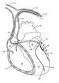
- FIG. 1is a diagrammatic representation of the human heart, showing a left ventricular endocardial lead system embodying the present invention.
- FIG. 1Ais a table showing the relationship between French sizes and millimeters and inches.
- FIG. 2is an enlarged perspective view of the lead system of FIG. 1 .
- FIG. 2Ais an enlarged view of the distal lead taken generally of the area indicated by the line 2 A in FIG. 2 .
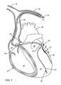
- FIG. 3is a diagrammatic representation of the human heart, showing epicardial lead attachment to the outside of the left ventricle in accordance with the present invention.
- FIG. 4is a cross-sectional view of an epicardial lead embodying the bandstop filter of the present invention taken generally along the line 4 - 4 in FIG. 3 .
- FIG. 5is an alternative epicardial lead tip taken generally along the line 4 - 4 in FIG. 3 .
- FIG. 6illustrates a split cylinder cuff electrode designed to wrap around a nerve.
- FIG. 7illustrates a self-sizing helical cuff coil including the bandstop filter chip of the present invention.
- FIG. 8is a sectional view taken generally along the line 8 - 8 in FIG. 7 .
- FIG. 9illustrates a nerve cuff employing a multiplicity of electrodes and bandstop filter chips for a large nerve trunk, in accordance with the present invention.
- FIG. 10illustrates one methodology of putting multiple bandstop filter chips in series with the leads of the multiple cuff electrode of FIG. 9 .
- FIG. 11illustrates a multi-conductor lead body connected to a multiple tank filter chip array that has multiple electrodes, in accordance with the present invention.
- FIG. 12is an exposed perspective view of one of many possible variations of the multiple bandstop filter array of FIG. 10 .
- FIG. 13is a diagrammatic, side cross-sectional view of the human head showing the placement of a deep brain probe and electrode embodying the bandstop filter of the present invention.
- FIG. 14is a diagrammatic, front cross-sectional view of the human head showing use of multiple deep brain probes.
- FIG. 15is an enlarged sectional view taken generally of the area indicated by the line 15 in FIG. 14 .
- FIG. 16is a view similar to FIG. 15 , illustrating an alternative probe and electrode arrangement.
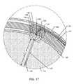
- FIG. 17is a sectional view similar to FIG. 15 , except that the probe containing the bandstop filter chip is embedded under the skull and then the skull bore hole is covered with a bone encapsulant.
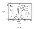
- FIG. 18is a graph of insertion loss verses frequency for bandstop filters having differing quality “Q” factors.
- FIG. 19is a perspective view of a distal electrode PAD applicable to a wide variety of neurostimulator applications
- FIG. 20is a sectional view taken generally along the line 130 - 130 of FIG. 19 ;
- FIG. 21is an exploded perspective view of an alternative structure accomplishing the same filtering result as the structure shown in FIGS. 19 and 20 ;
- FIG. 22is a vertical sectional view of the components illustrated in FIG. 21 , in their assembled configuration
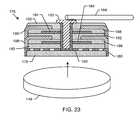
- FIG. 23is a sectional view similar to FIG. 22 , illustrating another alternative for building up the novel parallel inductor bandstop filter for neurostimulator applications;
- FIG. 24is an exploded perspective view of the components of the structure shown in FIG. 23 ;
- FIG. 25is a fragmented top plan view of an exemplary paddle or PAD electrode embodying the present invention.
- FIG. 26is a bottom plan view of the paddle or PAD electrode shown in FIG. 25 ;
- FIG. 27is an enlarged sectional view taken generally along the line 27 - 27 in FIG. 25 ;
- FIG. 28illustrates the distal end of a typical neurostimulator paddle electrode
- FIG. 29is similar to FIG. 28 , except that the paddle lead has been replaced with a series of flex cable electrodes;
- FIG. 30is an electrical schematic illustration of the bandstop filters found in the paddle electrodes of FIGS. 25-29 ;
- FIG. 31is a fragmented sectional view of a prior art neurostimulation electrode probe.
- FIG. 32is an enlarged sectional view of the area 32 in FIG. 31 , illustrating modifications to the prior art structure to incorporate the novel bandstop filters of the present invention.
- the present inventionis directed to medical lead systems comprising an implanted lead having a proximal end and an electrode in contact with biological cells at a distal end.
- At least one bandstop filteris associated with the lead for attenuating current flow through the lead over a range of frequencies.
- the bandstop filterhas an overall circuit Q wherein the resultant 3 dB bandwidth is at least 10 kHz and where the bandstop filter comprises a capacitor in parallel with an inductor.
- the parallel capacitor and inductorare placed in series with the lead wherein values of capacitance and inductance are selected such that the bandstop filter is resonant at a selected center frequency.
- the term bandwidthrefers to an attenuation or insertion loss plot of the bandstop filter performance versus frequency. At its resonant center frequency, the bandstop filter has an attenuation peak. The bandwidth is the difference in frequency either computed 3 dB or 10 dB down from the peak.
- FIG. 1is a diagrammatic representation of a human heart 20 which includes right and left subclavian veins 22 and 24 respectively, the superior vena cava 26 and the aorta 28 .
- a lead 30which is typically routed from a biventricular cardiac pacemaker or a biventricular implantable cardioverter defibrillator (ICD) (which are not shown), is routed through a catheter 31 and directed, in this case, through the left subclavian vein 24 and then down through the superior vena cava 26 and into the coronary sinus 32 .
- the lead 30must first enter the coronary sinus ostium 34 where the implanting physician selects the correct location.
- the coronary sinus 32is actually divided into two zones: the first part (on the left) is known as the coronary sinus 32 ; and the second part (on the right) is called the great cardiac vein 36 .
- the great cardiac vein 36wraps around the back of the left ventricle.
- the bandstop filter 38is intended to be placed ideally near the end of the great cardiac vein 36 where it breaks into several venous branches. These branches are called the posterior branch, the lateral branch 40 and the anterior branch 42 . A more comprehensive name, for example, would be the interventricular branch.
- FIG. 1one can also see the right ventricle 44 and the right atrium 46 . Also shown are the left atrium 48 and the left ventricle 50 .
- the ideal location for a bandstop filter 38is shown.
- An ideal length for the bandstop filter 38would be between 5 and 7.5 mm in length.
- cardiac motionis relatively small and fibrotic tissue will tend to encapsulate the bandstop filter 38 and its associated lead 30 and thereby attach it/fixate it in position in this relatively low motion region. This is particularly advantageous in that the lead 30 will remain highly reliable and resistant to breakage.
- this portion of the lead systemcan be of much larger diameter (for example, 7 or 8 French). Beyond this point, where the great cardiac vein 36 branches, the venous systems become much smaller. In general, these branches are below 6 French in diameter and ideal electrode sizes go all the way down to 3 French.
- FIG. 1Ashows the relationship between French size, millimeters and inches. Since left ventricular pacing is important for cardiac resynchronization and treatment of congestive heart failure, it is a feature of the present invention that a lead body diameter/size reduction occurs at distal end of the bandstop filter 38 allowing insertion of the smaller diameter/size lead extension 52 with distal electrodes into the small diameter venous system in the proper position outside the left ventricle 50 .
- the primary benefit of locating the bandstop filter 38 in the coronary sinus 32 and/or great cardiac vein 36is that the diameter of the bandstop filter 38 itself can be larger making it much easier to manufacture.
- the distal portion 52 of the lead 30 from the bandstop filter 38is smaller (3 to 6 French size) for easier employment and navigation into the branch veins of the left ventricle 50 .
- Secondary benefits beyond the diameter of the bandstop filter 38include the length of the bandstop filter. Entering into and navigating the coronary sinus 32 and great cardiac vein 36 generally involve larger bend radii compared to accessing and navigating the branch vessels. Therefore the lead extension 52 that traverses through and resides in the branch vessels must be very small and very flexible, not having a stiff section longer than approximately 1.5 mm as a rule of thumb.
- Rigid sections of the lead 30 measuring longer than 1.5 mmcan impede the ability to navigate around the tight corners and bends of the branch vessels.
- the coronary sinus 32 and great cardiac vein 36there is substantially more latitude, and stiff sections of the lead could approach 5 mm or even 7.5 mm without drastically impeding deliverability.
- a secondary benefit of locating the bandstop filter 38 in the coronary sinus 32 or the great cardiac vein 36has to do with MRI image artifacts. Although the image artifact will be quite small due to avoiding the use of ferromagnetic materials, it is still beneficial to locate the bandstop filter 38 away from the coronary arteries, ventricular wall motion or other anatomies/physiologies/pathologies of most interest. If a bandstop filter 38 is located in the coronary sinus 32 , however, it could generate small artifact in the vicinity of the valves.
- Another benefit of having the bandstop filter 38 located in the coronary sinus 32 or the great cardiac vein 36is that its rigidness provides a foundation on which optional fixation fixtures may be more strategically utilized.
- one or more tinescould originate from the region of the lead where the bandstop filter 38 resides. Additionally, rigidness of the bandstop filter 38 makes the tines more effective in their engagement of the vessel walls. Alternatively, a rigid portion of the lead 30 , skillfully navigated beyond a corner or bifurcation, can function as a fixation mechanism that proves difficult or requires skill to track the lead.
- the portion of an implanted lead 30 which is distal of a bandstop filteris known as the lead extension 52 .
- this lead extension 52 at its proximal endwill be connected to the bandstop filter 38 and its distal end will terminate in electrodes in contact with body cells or tissue.
- the electrical wave length ( ⁇ ) of the lead extension 52it is important that the electrical wave length ( ⁇ ) of the lead extension 52 not be physically too long. This has to with its efficiency as an antenna and picking up energy from the RF pulsed fields of an MRI system. In general, for 1.5 Tesla systems, lead lengths that couple very efficiently are in the 42 to 60 cm range.
- the length ( ⁇ ) of any lead extensionshould be less than 1 ⁇ 8 of an electrical wavelength (1 ⁇ 8 ⁇ ). It has been shown that leads that are less than 1 ⁇ 8 of electrical wavelength of the MRI RF frequency do not act as effective antennas and therefore pick up an insignificant amount of energy from the external MRI RF pulse field. In some cases, the electrical length of the lead extension could be as long as 1 ⁇ 4 or even 1 ⁇ 2 ⁇ . In these cases, variables include the lead trajectory, the sensitivity of the tissues that are in contact with a distal electrode, patient characteristics and the like. For example, myocardial tissue is much less subject to thermal damage than is deep brain tissue.
- FIG. 2is an enlarged perspective view of the lead system 30 taken from FIG. 1 .
- a guide wire 54which is common in the prior art for inserting into position prior to sliding the highly flexible lead system 30 down over it.
- a terminal pin 56is designed to plug into an implantable medical device, such as a pacemaker or ICD.
- the bandstop filter 38is shown at the point where the lead 30 would be reduced from 6-9 French down to the 3-6 French lead extension 52 .
- Optional fixation tines 57are shown which may be affixed, disposed, or adjacent to the bandstop filter 38 .
- the French scaleis related to both diameter in millimeters (mm) or inches.
- the electrical length ( ⁇ ) of the reduced diameter lead extension 52can be adjusted in accordance with the branch vein into which the lead system is being inserted in the desired location of the electrodes 58 .
- the guide wire 54is then removed.
- a particular advantage of the lead system 30 as shown in FIG. 2is that no new deployment instruments or catheters are required. In other words, this system that includes the bandstop filter 38 is backwards compatible with most known deployment systems. It is also very important that the lead system 30 is designed to be extracted in the case of a broken lead, defective lead or infected lead.
- the lead system illustrated in FIGS. 2 and 2Ais also backwards compatible with current mechanical and laser lead extraction technologies.
- each bandstop filter 38 and 38 ′associated with each of the distal electrodes 58 and 58 ′.
- Each bandstop filterconsists of a capacitor C in parallel with inductor L.
- These combined L-C bandstop filtersare placed in series with each one of the electrode lead conductors as shown.
- U.S. Pat. No. 7,363,090the contents of which are incorporated herein by reference.
- FIG. 3is a diagrammatic representation of the human heart similar to that illustrated in FIG. 1 .
- external (epicardial) electrodes 62are attached outside and to the left ventricle 50 by means of epicardial leads 60 .
- a sutureless myocardial lead 60 , 64is shown affixed to the outside of the left ventricle.
- This methodologyis well known and generally involves an insertion between the ribs outside of the heart and a screwdriver type feature to affix the sutureless epicardial lead tip electrode 62 in place.
- Epicardial leadsmay also have a suture feature which can have a helical or other configuration type tip. It should be apparent that the present invention can be extended to any type of external (epicardial) electrode 62 or satellite pacer affixed to the outside of the heart, particularly outside of the left ventricle.
- FIG. 4is a cross-sectional view taken generally along line 4 - 4 of FIG. 3 , illustrating an epicardial lead electrode assembly 62 which includes a bandstop filter 70 .
- the epicardial lead electrode assembly 62is typically over-molded with silicone rubber 66 .
- the assembly shown in FIG. 4is self-affixing to the myocardial tissue by a helical electrode structure 68 .
- this electrodeis affixed into the myocardium by 31 ⁇ 2 mechanical turns and is made of platinum-iridium alloy or equivalent biocompatible material.
- the helical electrode tip 68is affixed into the myocardial tissue by a screwdriver type turning surgical tool.
- the bandstop filter 70as illustrated in FIG.
- FIG. 4is taken generally from FIG. 42 of US 2007/0112398 A1. It will be apparent to those skilled in the art that almost all of the other novel bandstop filter embodiments that are disclosed in US 2007/0112398 A1 and U.S. Pat. No. 7,853,325 can be incorporated into the epicardial lead 62 in FIG. 4 .
- FIG. 5is very similar to the epicardial lead electrode assembly 62 shown in FIG. 4 , except that it has a novel ring structure 72 associated with a bandstop filter chip 70 .
- This epicardial bipolar electrodealso has a bandstop filter chip 70 ′ in series with its helical tip electrode 68 .
- a screwdriver type head mechanismcan be added for convenient adapting to prior art deployment instruments.
- any of the cylindrical bandstop filter chips as described in U.S. Pat. No. 7,853,325can also readily adapted to any of the novel bandstop filter applications as described herein.
- FIG. 6illustrates a split cylinder cuff electrode 74 embodying two electrodes (Anode (a) and Cathode (c)). This is designed to be inserted by a physician around a nerve. It is a bipolar system typically consisting of a 6-8 French diameter lead body 76 . A double bandstop filter chip 78 (two discrete bandstop filter chips in parallel) in accordance with the present invention is located as shown. In general, the cuff 74 is sized to match the diameter of the nerve which passes through its center. The lead body 76 , after the double bandstop filter 78 , is of a reduced diameter, generally in the 3-4 French range. Not shown is a closing suture which is typically used to draw the cuff together after it's installed.
- FIG. 7illustrates helical nerve cuffs 80 which are self-sizing. These incorporate electrode foils 82 which are well known in the prior art.
- the lead body 84is attached to a bandstop filter 86 of the present invention. This can be unipolar or bipolar as shown.
- the electrode foil 82can either be etched or stamped and then the termination point where the conductor attaches to the foil is either prepared or fabricated. This is the location to where the bandstop filter 86 is electrically attached and incorporated.
- the conductors and the foil 82 on the bandstop filter 86are laid into a split mold and assembled and then silicone is injected into the mold.
- FIG. 7illustrates one leg of a bipolar or multipolar lead. Obviously, a bandstop filter 86 would be required for each electrode foil in the multipolar configuration.
- FIG. 8is an enlarged sectional view taken generally along line 8 - 8 of FIG. 7 .
- FIG. 9illustrates a larger multiple cuff nerve electrode 88 for current steering in a large nerve trunk.
- Various electrodescan be stimulated by trial and error to obtain the optimal result. For example, for pain control, one can try various electrodes and various types of electrical stimulation by trial and error until pain is minimized or eliminated.
- the multiple parallel filter electrodes 90similar to that described in FIG. 4 , can be placed in conjunction with each one of the conductors 92 as shown.
- FIG. 10illustrates an alternative in that a multiple bandstop filter array 94 is shown in series with the lead body 96 .
- Thiscan in turn be connected as a lead extension (beyond the bandstop filter(s)).
- Itcan also be adapted to the multiple single electrodes illustrated in FIG. 11 .
- the multiple bandstop chip as illustrated in FIGS. 10 and 11can be made in a variety of ways utilizing the technology disclosed in US 2007/0112398 A1 and U.S. Pat. No. 7,853,325, by putting the devices on a substrate next to each other on each lead.
- the structure shown in FIGS. 10 and 11can be over-molded with silicone or the like to provide reliable mechanical attachment and protection from body fluids.
- FIG. 12is taken generally along the line 12 - 12 from FIG. 10 , and illustrates one of many ways to form a multiple array 98 of bandstop filter chips.
- a thin substrate 100which can be of alumina or any other substrate material known in the prior art.
- Different types of bandstop filters 102 a - f(MRI chips) are shown by way of illustrating that there are many ways to construct this multiple array 98 .
- the MRI chips 102 a - fare similar to FIGS. 80-85 and FIG. 136 (which is thick film deposited right on the substrate).
- imbedded or MEMs componentscan also be used to form the multiple bandstop MRI filter array 98 .
- multilayer substratesmay be used to increase packaging density.
- Wirebond pads 104 , leads 106 and 106 ′ and electrical connections 108are also shown.
- the bandstop filter chips 102 a - fhave end terminations 110 as shown. There are electrical connections from these end terminations 110 to the circuit traces 112 .
- the entire assemblyis desirably over coated, over molded (with silicone or the like), or glass encapsulated to enhance mechanical strength and biocompatibility.
- FIG. 13is a diagrammatic side cross-sectional view of the human head showing the skull 114 and the brain 116 .
- a burr hole 118is drilled through the skull 114 for placement of deep brain probe 120 with associated electrodes 122 .
- the deep brain probe 120is equivalent to a lead extension in that the bandstop filter(s) is placed within burr hole container 126 . This allows for the deep brain probe 120 and its associated electrodes 122 to be very small in diameter which is equivalent to the lead extension l previously discussed in FIG. 1 .
- the distal end of the lead 124is generally connected to an AIMD (not shown) such as a pulse generator.
- the AIMDmay be located somewhere in the patient's skull or tunneled through the neck and located in a pectoral implant region.
- One or more bandstop filtersare located inside of the skull burr hole 118 in housing 126 .
- the bandstop filter housing 126may be located within the burr hole, above the burr hole, or even in the dural or subdural.
- FIG. 14is a diagrammatic cross-sectional front view of the human head, showing that there can be multiple deep brain probes 120 . . . 120 n placed as previously described in connection with FIG. 13 .
- the top of the deep brain probe 120 and associated bandstop filters 126 , 126 ′would be flush with the top of the skull 114 .
- the lead 124is generally connected to a pulse generator or transmitter which is either implanted or can sit outside the skin. There can also be a receiver which sits on the skin.
- the deep brain probe 120can also have a nail head or nail shank.
- FIG. 15is an enlarged sectional view of the area indicated by line 15 in FIG. 14 , of the deep brain probe 120 . Shown are the locations of the L-C bandstop filters 126 , 126 ′, 126 ′′, and 126 ′′′, the skin 128 which covers the skull 114 , the lead 124 , the burr hole 118 , dura layer 130 and the brain 116 . At the end of the deep brain probe 120 are electrodes 132 .
- FIG. 16illustrates an alternative view wherein a highly flexible region 134 is connected between the bandstop filter array 126 and the electrodes 132 .
- This flexible section 134provides strain relief for the relative motion between the skull 114 and the brain 116 .
- the deep brain probes 120 - 120 nform a lead extension (l) which is functionally equivalent to the lead extension 52 described previously.
- the electrical length of this lead extension 120should be less than 1 ⁇ 2 wavelength of the MRI RF pulse frequency (in body tissue), and preferably less than 1 ⁇ 4 or 1 ⁇ 8 wavelength. In this particular case, since the deep brain probe 120 is implanted into thermally sensitive brain tissue, the electrical length (l) of the lead extension should be less than 1 ⁇ 8 wavelength.
- FIG. 17illustrates an alternate configuration similar to FIG. 15 , wherein the top of the bandstop filter array 126 is disposed below the skull 114 .
- the burr hole 118is covered with a bone encapsulant 136 . It will be apparent to those skilled in the art that the deep brain probe 120 , and its associated bandstop filter array 126 , can be placed in various locations that are convenient for the physician/surgeon.
- the bandstop filterbe as close to the electrode-to-tissue interface as possible.
- the lead and its associated conductorscan act as an antenna (and also as a transmission line).
- an antennais an efficient multiple of a wavelength, it can pick up a great deal of energy from the external environment.
- the RF pulse fields from an MRI scannercan induce high levels of current in implanted leads and their associated electrodes, which can be damaging to body tissue.
- the length of the lead extension (l), shown as element 52 in FIG. 1 and 120 in FIGS. 15 and 16should be as short as possible.
- the bandstop filtershould be placed in relatively close proximity to the therapy sense or delivery electrodes as illustrated.
- the bandstop filteris no more than 15 cm away from the delivery electrode. This will provide effective reduction in current flow at the MRI RF pulsed frequency thereby providing effective cooling at the distal electrode tips.
- the efficiency of the bandstop filters( 38 , 70 , 86 , 102 , 126 ) are also measured in terms of a quality factor, Q.
- the bandstop filter circuit Qis typically expressed using the following equation:
- f ris the resonance frequency
- ⁇ f 3dB shown as points a and b in FIG. 18is the 3 dB bandwidth of the bandstop filter.
- Bandwidthis typically taken as the difference between the two measured frequencies, f 1 , and f 2 , at the 3 dB down points as measured on an insertion loss curve, and the resonance center frequency is the average between f 1 , and f 2 .
- the 3 dB bandwidthis f 2 -f 1 measured in either kHz or MHz
- the 10 dB down pointsare shown as points “c” and “d” in FIG. 18 and correspond with frequencies f 3 and f 4 . Accordingly, the 10 dB bandwidth is f 4 -f 3 measured either in kHz or MHz.
- the insertion loss curvecan also be equated to an attenuation curve wherein the source and load impedances would be 50 ohms.
- the source impedancewould be the source impedance of the lead and body tissue and the load impedance would be the input impedance of the AIMD itself.
- resistors R C and R Lrepresent the equivalent series resistance of the capacitor C, or a discrete series resistor added in series with the capacitor.
- R Lrepresents the equivalent series resistance of the inductor L, which is commonly due to the resistance of the wire turns or wire circuit traces of the inductor.
- R Lcould also be a separate discrete chip resistor or other type of resistor added in series with the inductor portion of the bandstop filter 138 . Controlling the values of these resistances controls the 3 dB bandwidths and hence the quality factor Q of the bandstop filter.
- Both the 3 dB bandwidth and the 10 dB bandwidthcan be varied in accordance with the application.
- the applicationis for a very specific situation, for example a dedicated MRI guided catheter lab, then only one MRI scanner is involved.
- the bandstop filter 138could be designed with relatively narrow 3 dB and the 10 dB bandwidths.
- the 10 dB bandwidthcould be as small as 10 kHz.
- the gradient field of the MRI scannergrades the main static field.
- the 10 dB bandwidthwould be on the order of megahertz, or a minimum of 500 kHz.
- the bandstop filter 138would be effective over the range of commercially available or labeled 1.5 Tesla MRI scanners. Similar principles apply to 3 Tesla, 5 Tesla and other scanners that have a different static magnetic field strength. In these cases, the RF pulsed frequencies are much higher in frequency and their variation between different manufacturers and also their variation because of the gradient field can be even greater as measured in kHz.
- the bandstop filter 138represent a very low impedance. This is because the bandstop filter must pass both pacing and biologic sensing signals with very little attenuation. The same is true of very high frequencies as shown by f H although in this case it would not matter if the bandstop filter offered additional attenuation since there are no biological signals in this range.
- the “Q” or quality factor of the bandstop circuit 138is very important. As mentioned, it is desirable to have a very low loss circuit at low frequencies such that the biological signals not be undesirably attenuated.
- the quality factor Qnot only determines the loss of the filter, but also affects its 3 dB and 10 dB bandwidths. If one does a plot of the filter response curve (Bode plot), the 3 dB and 10 dB bandwidths determine the attenuation curve, shape and how sharply the filter will rise and fall. With reference to curve 140 of FIG.
- the performance of the circuitis directly related to the efficiency of both the inductor L and the capacitor C; the less efficient each component is, the more heat loss that results, and this can be expressed by the addition of resistor elements, R C and R L to the ideal circuit diagram.
- the effect of lower Q in the bandstop circuit 138is to broaden the resonance peak about the resonance frequency. By deliberately using a low Q capacitor and/or inductor, one can broaden the resonance such that a moderately high impedance (attenuation) is presented at multiple MRI RF frequencies.
- a good way to control the Q of the bandstop filter 138is to establish resistance R L that is consistent with the parasitic resistances of inductor windings or turns and also carefully control the capacitor Q.
- Another reason that one must control the resistive loss R L of the inductor Lis that if the resistance gets too high, excessive heating of the bandstop filter could occur. This is because there is a high frequency current that oscillates at the MRI pulsed frequency between the capacitor's C electric field and the inductor's L magnetic field. This circulating current can create heating about the bandstop filter in one of two ways: 1) by I 2 R heating in either resistance R L or R C (or both), or by eddy current losses in the hermetic or shield housing that surrounds the bandstop filter. Accordingly, a careful balance between component design and bandstop filter Q must be achieved.
- the bandstop filter 138is designed to be resonant at a center frequency, f r representing the center of a range of RF pulsed frequencies. As shown in FIG.
- a resistance element R C , R L or bothis added in order to increase the 3 dB bandwidth of the L-C trap filter 138 .
- R Cresistance element
- R Lresistance element
- FIG. 18one can see the attenuation curve for a high Q filter 140 , a medium Q filter 144 , and a low Q filter 142 .
- the medium Q filterwould work for many applications, but the attenuation of the low Q filter generally would not be adequate to be sure that excessive heating at a distal electrode would not occur.
- the desired curve shapesare 140 or 144 .
- the filter response curvewould look like a straight up and down line (not shown) centered above f r .
- This resistance elementcan be a discrete resistor or it can be formed from the leads or circuit traces as a parasitic element that forms the inductance L itself.
- this resistance elementis not shown in FIG. 16 and the subsequent drawings.
- the bandstop filteris designed to attenuate over a range of MRI RF pulsed frequencies on the order of tens of kilohertz, hundreds of kilohertz, or even megahertz.
- FIG. 19illustrates a distal PAD electrode 146 applicable to a wide variety of neurostimulator applications.
- Neurostimulatorsinclude cochlear implants, deep brain stimulators, spinal cord stimulators, incontinence stimulators, general pain control stimulators, vagus nerve stimulators, Parkinson's tremor control stimulators and the like.
- Typical prior art stimulatorsoften come with a variety of PAD electrodes such as that shown in FIG. 19 .
- Three neurostimulation electrodes 148 , 148 ′ and 148 ′′are shown, however, these can vary anywhere from one, ten or even twenty-four or more neurostimulation electrodes.
- cochlear neurostimulatorsthere are commonly sixteen conductors, which are routed to a bundle of sixteen electrodes to make contact to the auditory nerves.
- lead body 150which contains three conductors that are connected to an external or implanted active medical device (not shown).
- FIG. 20is a cross-sectional view taken generally along line 20 - 20 of FIG. 19 , and illustrates one form of the novel inductor-capacitor bandstop filter 152 of the present invention.
- a discoidal feedthrough capacitor 154with an air core inductor 156 running through its center.
- the distal PAD electrode 148has a laser weld or equivalent biocompatible electrical attachment 160 to the surrounding metallization of the capacitor 154 .
- Lead 164is then routed through the flexible neurostimulator PAD electrode 146 as shown in FIG. 19 . Lead 164 becomes part of the lead body 150 which would be routed to the AIMD.
- FIGS. 21 and 22show alternative ways of accomplishing the same thing using a feedthrough capacitor structure as described in FIGS. 115 and 118 US 2007/0112398 A1 in the PAD electrode 166 of FIG. 20 .
- the inductor 168has been printed onto the top of the capacitor 154 or attached to the capacitor by means of a supplemental substrate.
- Lead 164is connected to the capacitor's internal diameter metallization 168 as shown using an intermediate contact plate 170 .
- the PAD electrode 148is electrically and mechanically attached to the capacitor outside diameter metallization 172 , but electrically insulated from the internal metallization 168 , such as with an insulative layer or liner 174 . This is shown inverted for simplicity as compared to FIG. 19 .
- FIG. 23illustrates another alternative using thick film techniques to build up in layers a parallel inductor bandstop filter for neurostimulator applications as previously shown in FIG. 19 .
- this electrode assembly 176is shown inverted for simplicity.
- the distal PAD electrode 148forms a substrate such as used for thick film deposition of various capacitor and inductor layers.
- the structure 176 of FIG. 23is better understood by looking at the exploded view in FIG. 24 .
- An insulative layer 178is first imprinted on this conductive electrode 148 and then one or more inductor layers 180 are imprinted thereon. Then another insulative layer 182 is laid on top of the inductor layer 180 .
- capacitor inner diameter electrode 184is printed.
- another insulative layer 186is printed.
- an outside diameter capacitor electrode 188is imprinted.
- Many alternating layers of electrodes 184 and 188can be stacked up as desired to achieve the required capacitance value.
- an overall insulative layer 190is laid down. As is well known in conventional thick film or tape manufacturing processes, there is usually a drying step between each one of these operations. The entire structure is then sintered at high temperature to form a rugged monolithic structure.
- An electrical contact 192is then inserted using a suitable electrical connection material to make contact with both the inside diameter of the inductor 180 and the inside diameter of the inner diameter capacitor electrode plate stack 184 .
- neurostimulator lead 164is electrically connected to this contact insert 192 .
- the outside diameter of the inductormakes contact with neurostimulator electrode PAD 148 .
- the capacitor's ground electrode plates 188also make electrical contact with the distal electrode PAD 148 . This has the effect of putting the capacitance in parallel with the inductance.
- FIG. 25illustrates a paddle or PAD electrode array 194 which could be used, for example, in spinal cord simulator applications. It has eight electrodes 196 housed in a biocompatible insulative and flexible body 198 . An eight conductor lead 200 (there can be any number) is connected respectively to each of the eight electrodes 196 . As previously discussed, the elongated lead 200 can pick up significant amounts of RF energy during MRI scanning. It is very important that the electrodes 196 do not overheat since they are in direct contact with body tissue, for example, with the spinal cord.
- FIG. 26illustrates the reverse side of the paddle electrode 194 .
- FIG. 27is a sectional view taken of section 27 - 27 from FIG. 25 . Shown are the eight electrode PADs 196 each of which is connected in series with a bandstop filter 202 of the present invention. Accordingly, there are eight electrode PADs 196 in contact with body tissue, there are eight bandstop filters 202 and eight conductors that make up the lead bundle 200 . Referring once again to FIG. 27 , if it were necessary to save space, the bandstop filters 202 could be placed at a point proximal from the electrode PAD array. The electrodes would then be located at the distal end of a lead extension in accordance with the present invention. One example would be as illustrated in FIG.
- FIG. 28illustrates the distal end of a typical neurostimulator paddle electrode 204 , which in this case has eight electrode contact points 206 . In this case, each of these eight electrodes 206 would have in series with it a bandstop filter 208 as shown in FIG. 30 .
- FIG. 29is similar to FIG. 28 except the paddle lead 210 ( FIG. 28 ) has been replaced with a series of flex cable electrode conductors 212 . Again, each of the electrodes 206 has in series with it a bandstop filter 208 .
- FIG. 31illustrates a prior art neurostimulation electrode probe 214 or a common ablation probe or a catheter. As one can see, there are a multiplicity of stimulation electrodes 216 - 216 ′′′. In this particular application the end tip 218 is insulative.
- FIG. 32is the probe 214 , neurostimulation tip 218 , ablation probe or catheter of FIG. 31 , modified to include novel bandstop filters 220 and 220 ′ of the present invention.
- novel bandstop filters 220 and 220 ′ of the present inventionare placed in conjunction with the stimulation electrodes 216 , 216 ′ and so on. As many as desired can be stacked as shown. This has the effect of placing the bandstop filter 220 of the present invention in series with each one of the stimulation rings 216 and thereby limiting/preventing the flow of MRI induced RF currents.
- a common application for the type of electrode probe arrangement shown in FIG. 31would be a cochlear implant wherein there would be sixteen ring electrodes 216 .
- FIG. 31illustrates the prior art and FIG.
- FIG. 32illustrates the principles of the present invention wherein a bandstop filter BSF has been placed in series with each of the electrodes 216 .
- the probe or catheter of FIG. 32could also be configured as a lead extension as previously described.
- the bandstop filters 220 , 220 ′ and so oncould be located at the proximal end of the lead extension. This would allow the probe and its associated electrodes to be smaller in diameter for specific physiological applications.
- the medical lead systems illustrated and describedmay be advantageously used in a number of environments, with different types of active implantable medical devices (AIMDs) and with different types of MRI equipment.
- a precise construction and configuration of the bandstop filters utilized with the lead systemsmay have a wide variety of configurations and applications as illustrated in U.S. Pat. No. 7,363,090; U.S. Pat. No. 7,853,324; U.S. Pat. No. 7,702,387; U.S. Pat. No.
Landscapes
- Health & Medical Sciences (AREA)
- Nuclear Medicine, Radiotherapy & Molecular Imaging (AREA)
- Animal Behavior & Ethology (AREA)
- Veterinary Medicine (AREA)
- Cardiology (AREA)
- Heart & Thoracic Surgery (AREA)
- Engineering & Computer Science (AREA)
- Public Health (AREA)
- Radiology & Medical Imaging (AREA)
- Biomedical Technology (AREA)
- Life Sciences & Earth Sciences (AREA)
- General Health & Medical Sciences (AREA)
- Neurology (AREA)
- Neurosurgery (AREA)
- Orthopedic Medicine & Surgery (AREA)
- Electrotherapy Devices (AREA)
Abstract
Description
Where fris the resonance frequency, and Δf3dBshown as points a and b in
Claims (23)
Priority Applications (1)
| Application Number | Priority Date | Filing Date | Title |
|---|---|---|---|
| US13/312,741US8224462B2 (en) | 2005-11-11 | 2011-12-06 | Medical lead system utilizing electromagnetic bandstop filters |
Applications Claiming Priority (6)
| Application Number | Priority Date | Filing Date | Title |
|---|---|---|---|
| US59712505P | 2005-11-11 | 2005-11-11 | |
| US80367206P | 2006-06-01 | 2006-06-01 | |
| US11/423,073US8244370B2 (en) | 2001-04-13 | 2006-06-08 | Band stop filter employing a capacitor and an inductor tank circuit to enhance MRI compatibility of active medical devices |
| US11/558,349US7945322B2 (en) | 2005-11-11 | 2006-11-09 | Tank filters placed in series with the lead wires or circuits of active medical devices to enhance MRI compatibility |
| US11/943,883US7899551B2 (en) | 2001-04-13 | 2007-11-21 | Medical lead system utilizing electromagnetic bandstop filters |
| US13/312,741US8224462B2 (en) | 2005-11-11 | 2011-12-06 | Medical lead system utilizing electromagnetic bandstop filters |
Related Parent Applications (1)
| Application Number | Title | Priority Date | Filing Date |
|---|---|---|---|
| US11/943,883Continuation-In-PartUS7899551B2 (en) | 2001-04-13 | 2007-11-21 | Medical lead system utilizing electromagnetic bandstop filters |
Publications (2)
| Publication Number | Publication Date |
|---|---|
| US20120078333A1 US20120078333A1 (en) | 2012-03-29 |
| US8224462B2true US8224462B2 (en) | 2012-07-17 |
Family
ID=45871405
Family Applications (1)
| Application Number | Title | Priority Date | Filing Date |
|---|---|---|---|
| US13/312,741ActiveUS8224462B2 (en) | 2005-11-11 | 2011-12-06 | Medical lead system utilizing electromagnetic bandstop filters |
Country Status (1)
| Country | Link |
|---|---|
| US (1) | US8224462B2 (en) |
Cited By (17)
| Publication number | Priority date | Publication date | Assignee | Title |
|---|---|---|---|---|
| US20140240060A1 (en)* | 2006-06-08 | 2014-08-28 | Greatbatch Ltd. | Emi filter employing a self-resonant inductor bandstop filter having optimum inductance and capacitance values |
| WO2018183567A1 (en) | 2017-03-29 | 2018-10-04 | Tc1 Llc | Communication methods and architecture for heart treatment systems |
| WO2018183565A1 (en) | 2017-03-29 | 2018-10-04 | Harjes Daniel I | Adjusting protocol based on irregular heart rhythm |
| US10154616B2 (en) | 2012-09-05 | 2018-12-11 | Avx Corporation | Electromagnetic interference filter for implanted electronics |
| US10363425B2 (en) | 2015-06-01 | 2019-07-30 | Avx Corporation | Discrete cofired feedthrough filter for medical implanted devices |
| US10406350B2 (en) | 2008-11-12 | 2019-09-10 | Ecole Polytechnique Federale De Lausanne | Microfabricated neurostimulation device |
| WO2019182761A1 (en) | 2018-03-19 | 2019-09-26 | Tc1 Llc | Coordinated ventricular assist and cardiac rhythm management devices and methods |
| US10441779B2 (en) | 2014-08-27 | 2019-10-15 | Aleva Neurotherapeutics | Deep brain stimulation lead |
| US10695556B2 (en) | 2010-04-01 | 2020-06-30 | Ecole Polytechnique Federale De Lausanne | Device for interacting with neurological tissue and methods of making and using the same |
| US10702692B2 (en) | 2018-03-02 | 2020-07-07 | Aleva Neurotherapeutics | Neurostimulation device |
| US10835654B2 (en) | 2017-03-29 | 2020-11-17 | Tc1 Llc | Pressure sensing ventricular assist devices and methods of use |
| US10874865B2 (en) | 2017-11-06 | 2020-12-29 | Avx Corporation | EMI feedthrough filter terminal assembly containing a resin coating over a hermetically sealing material |
| US10952627B2 (en) | 2008-07-30 | 2021-03-23 | Ecole Polytechnique Federale De Lausanne | Apparatus and method for optimized stimulation of a neurological target |
| US10966620B2 (en) | 2014-05-16 | 2021-04-06 | Aleva Neurotherapeutics Sa | Device for interacting with neurological tissue and methods of making and using the same |
| US11241570B2 (en) | 2018-07-17 | 2022-02-08 | Tc1 Llc | Systems and methods for inertial sensing for VAD diagnostics and closed loop control |
| US11311718B2 (en) | 2014-05-16 | 2022-04-26 | Aleva Neurotherapeutics Sa | Device for interacting with neurological tissue and methods of making and using the same |
| US11517740B2 (en) | 2018-03-15 | 2022-12-06 | Tc1 Llc | Methods for controlling a left ventricular assist device |
Families Citing this family (4)
| Publication number | Priority date | Publication date | Assignee | Title |
|---|---|---|---|---|
| EP2848282B1 (en)* | 2013-09-13 | 2016-08-10 | BIOTRONIK SE & Co. KG | Implantable device |
| EP3454935B1 (en)* | 2016-05-11 | 2024-07-24 | Inspire Medical Systems, Inc. | Attenuation arrangement for implantable medical device |
| AU2021300986A1 (en)* | 2020-07-03 | 2023-01-19 | Neuronano Ab | Microelectrode for insertion into soft tissue |
| MX2024008488A (en)* | 2022-01-05 | 2024-07-15 | Neuronano Ab | Microelectrode for insertion into soft tissue. |
Citations (85)
| Publication number | Priority date | Publication date | Assignee | Title |
|---|---|---|---|---|
| US3871382A (en) | 1973-02-15 | 1975-03-18 | Pacesetter Syst | Heart stimulator system for rapid implantation and removal with improved integrity |
| US3968802A (en) | 1975-01-24 | 1976-07-13 | Medtronic, Inc. | Cautery protection circuit for a heart pacemaker |
| JPS60141034A (en) | 1983-12-09 | 1985-07-26 | コックリアー コーポレーション | Signal transmitter |
| JPS61181925A (en) | 1985-02-06 | 1986-08-14 | Toyo Commun Equip Co Ltd | Temperature sensor |
| US4633181A (en) | 1983-08-11 | 1986-12-30 | Regents Of The University Of Calif. | Apparatus and method for increasing the sensitivity of a nuclear magnetic resonance probe |
| JPS62233905A (en) | 1986-03-31 | 1987-10-14 | ナシヨナル・エアロノ−テイツクス・アンド・スペ−ス・アドミニストレ−シヨン | Temperature sensitive transmitter |
| US4799499A (en) | 1985-08-17 | 1989-01-24 | Bisping Hans Juergen | Implantable electrode with active fixation means |
| US4858623A (en) | 1987-07-13 | 1989-08-22 | Intermedics, Inc. | Active fixation mechanism for lead assembly of an implantable cardiac stimulator |
| JPH0471536A (en) | 1990-07-12 | 1992-03-06 | Toshiba Corp | Ecg signal cable for mri device |
| US5209233A (en) | 1985-08-09 | 1993-05-11 | Picker International, Inc. | Temperature sensing and control system for cardiac monitoring electrodes |
| US5217010A (en) | 1991-05-28 | 1993-06-08 | The Johns Hopkins University | Ecg amplifier and cardiac pacemaker for use during magnetic resonance imaging |
| US5246438A (en) | 1988-11-25 | 1993-09-21 | Sensor Electronics, Inc. | Method of radiofrequency ablation |
| US5300108A (en) | 1993-01-05 | 1994-04-05 | Telectronics Pacing Systems, Inc. | Active fixation lead with a dual-pitch, free spinning compound screw |
| US5333095A (en) | 1993-05-03 | 1994-07-26 | Maxwell Laboratories, Inc., Sierra Capacitor Filter Division | Feedthrough filter capacitor assembly for human implant |
| US5363845A (en) | 1993-08-13 | 1994-11-15 | Medical Advances, Inc. | Breast coil for magnetic resonance imaging |
| US5398683A (en) | 1991-05-24 | 1995-03-21 | Ep Technologies, Inc. | Combination monophasic action potential/ablation catheter and high-performance filter system |
| US5545201A (en) | 1995-03-29 | 1996-08-13 | Pacesetter, Inc. | Bipolar active fixation lead for sensing and pacing the heart |
| US5629622A (en) | 1995-07-11 | 1997-05-13 | Hewlett-Packard Company | Magnetic field sense system for the protection of connected electronic devices |
| US5697958A (en) | 1995-06-07 | 1997-12-16 | Intermedics, Inc. | Electromagnetic noise detector for implantable medical devices |
| US5716390A (en) | 1996-08-09 | 1998-02-10 | Pacesetter, Inc. | Reduced diameter active fixation pacing lead using concentric interleaved coils |
| US5722998A (en) | 1995-06-07 | 1998-03-03 | Intermedics, Inc. | Apparatus and method for the control of an implantable medical device |
| US5741321A (en) | 1996-01-11 | 1998-04-21 | Medtronic, Inc. | Active fixation medical electrical lead having improved turning tool |
| US5751539A (en) | 1996-04-30 | 1998-05-12 | Maxwell Laboratories, Inc. | EMI filter for human implantable heart defibrillators and pacemakers |
| US5759202A (en) | 1997-04-28 | 1998-06-02 | Sulzer Intermedics Inc. | Endocardial lead with lateral active fixation |
| WO1999019739A1 (en) | 1997-10-13 | 1999-04-22 | Andreas Melzer | Mr imaging method and medical device for use in method |
| US5905627A (en) | 1997-09-10 | 1999-05-18 | Maxwell Energy Products, Inc. | Internally grounded feedthrough filter capacitor |
| JPH11239572A (en) | 1997-12-16 | 1999-09-07 | Koninkl Philips Electronics Nv | Mr system, medical treatment system and localization method |
| US5959829A (en) | 1998-02-18 | 1999-09-28 | Maxwell Energy Products, Inc. | Chip capacitor electromagnetic interference filter |
| US5964705A (en) | 1997-08-22 | 1999-10-12 | Image-Guided Drug Delivery System, Inc. | MR-compatible medical devices |
| US5973906A (en) | 1998-03-17 | 1999-10-26 | Maxwell Energy Products, Inc. | Chip capacitors and chip capacitor electromagnetic interference filters |
| US5978204A (en) | 1995-11-27 | 1999-11-02 | Maxwell Energy Products, Inc. | Capacitor with dual element electrode plates |
| US6008980A (en) | 1997-11-13 | 1999-12-28 | Maxwell Energy Products, Inc. | Hermetically sealed EMI feedthrough filter capacitor for human implant and other applications |
| US6055457A (en) | 1998-03-13 | 2000-04-25 | Medtronic, Inc. | Single pass A-V lead with active fixation device |
| US6101417A (en) | 1998-05-12 | 2000-08-08 | Pacesetter, Inc. | Implantable electrical device incorporating a magnetoresistive magnetic field sensor |
| US6141594A (en) | 1998-07-22 | 2000-10-31 | Cardiac Pacemakers, Inc. | Single pass lead and system with active and passive fixation elements |
| US6159560A (en) | 1998-11-25 | 2000-12-12 | Stevenson; Robert A. | Process for depositing a metal coating on a metallic component of an electrical structure |
| US6275369B1 (en) | 1997-11-13 | 2001-08-14 | Robert A. Stevenson | EMI filter feedthough terminal assembly having a capture flange to facilitate automated assembly |
| US6424234B1 (en) | 1998-09-18 | 2002-07-23 | Greatbatch-Sierra, Inc. | Electromagnetic interference (emi) filter and process for providing electromagnetic compatibility of an electronic device while in the presence of an electromagnetic emitter operating at the same frequency |
| US6456481B1 (en) | 2001-05-31 | 2002-09-24 | Greatbatch-Sierra, Inc. | Integrated EMI filter-DC blocking capacitor |
| WO2002083016A1 (en) | 2001-04-13 | 2002-10-24 | Surgi-Vision, Inc. | Systems and methods for magnetic-resonance-guided interventional procedures |
| US6473291B1 (en) | 1999-03-16 | 2002-10-29 | Gb Aquisition Co., Inc. | Low inductance four terminal capacitor lead frame |
| US6493591B1 (en) | 2000-07-19 | 2002-12-10 | Medtronic, Inc. | Implantable active fixation lead with guidewire tip |
| US20030028094A1 (en) | 1996-04-25 | 2003-02-06 | Ananda Kumar | Biopsy and sampling needle antennas for magnetic resonance imaging-guided biopsies |
| US6529103B1 (en) | 2000-09-07 | 2003-03-04 | Greatbatch-Sierra, Inc. | Internally grounded feedthrough filter capacitor with improved ground plane design for human implant and other applications |
| US6529000B2 (en) | 2000-12-29 | 2003-03-04 | Ge Medical Systems Global Technology Company, Llc | Method and system for processing magnetic resonance signals to remove transient spike noise |
| US20030050557A1 (en) | 1998-11-04 | 2003-03-13 | Susil Robert C. | Systems and methods for magnetic-resonance-guided interventional procedures |
| US6535766B1 (en) | 2000-08-26 | 2003-03-18 | Medtronic, Inc. | Implanted medical device telemetry using integrated microelectromechanical filtering |
| US6539253B2 (en) | 2000-08-26 | 2003-03-25 | Medtronic, Inc. | Implantable medical device incorporating integrated circuit notch filters |
| US6567259B2 (en) | 2001-05-31 | 2003-05-20 | Greatbatch-Sierra, Inc. | Monolithic ceramic capacitor with barium titinate dielectric curie point optimized for active implantable medical devices operating at 37° C. |
| US6567703B1 (en) | 2000-11-08 | 2003-05-20 | Medtronic, Inc. | Implantable medical device incorporating miniaturized circuit module |
| US6606513B2 (en) | 2000-02-01 | 2003-08-12 | Surgi-Vision, Inc. | Magnetic resonance imaging transseptal needle antenna |
| US6643903B2 (en) | 1997-11-13 | 2003-11-11 | Greatbatch-Sierra, Inc. | Process for manufacturing an EMI filter feedthrough terminal assembly |
| US6675033B1 (en) | 1999-04-15 | 2004-01-06 | Johns Hopkins University School Of Medicine | Magnetic resonance imaging guidewire probe |
| US6675779B2 (en) | 2002-06-13 | 2004-01-13 | Stant Manufacturing Inc. | Dual float valve for fuel tank vent with liquid carryover filter |
| US6687550B1 (en) | 2001-06-01 | 2004-02-03 | Pacesetter, Inc. | Active fixation electrode lead having an electrical coupling mechanism |
| US6701176B1 (en) | 1998-11-04 | 2004-03-02 | Johns Hopkins University School Of Medicine | Magnetic-resonance-guided imaging, electrophysiology, and ablation |
| US6765780B2 (en) | 2002-02-28 | 2004-07-20 | Greatbatch-Sierra, Inc. | EMI feedthrough filter terminal assembly having surface mounted, internally grounded hybrid capacitor |
| US20040263174A1 (en) | 2003-06-24 | 2004-12-30 | Biophan Technologies, Inc. | Magnetic resonance imaging interference immune device |
| US6868288B2 (en) | 2000-08-26 | 2005-03-15 | Medtronic, Inc. | Implanted medical device telemetry using integrated thin film bulk acoustic resonator filtering |
| US6876885B2 (en) | 2001-01-31 | 2005-04-05 | Medtronic, Inc. | Implantable bifurcated gastrointestinal lead with active fixation |
| US6882248B2 (en) | 2000-09-07 | 2005-04-19 | Greatbatch-Sierra, Inc. | EMI filtered connectors using internally grounded feedthrough capacitors |
| US6898454B2 (en) | 1996-04-25 | 2005-05-24 | The Johns Hopkins University | Systems and methods for evaluating the urethra and the periurethral tissues |
| US6925328B2 (en) | 2000-04-20 | 2005-08-02 | Biophan Technologies, Inc. | MRI-compatible implantable device |
| US6931286B2 (en) | 2002-10-02 | 2005-08-16 | Medtronic, Inc. | Delivery of active fixation implatable lead systems |
| US20050197677A1 (en) | 2004-02-12 | 2005-09-08 | Stevenson Robert A. | Apparatus and process for reducing the susceptability of active implantable medical devices to medical procedures such as magnetic resonance imaging |
| US6952613B2 (en) | 2001-01-31 | 2005-10-04 | Medtronic, Inc. | Implantable gastrointestinal lead with active fixation |
| US6971391B1 (en) | 2002-12-18 | 2005-12-06 | Nanoset, Llc | Protective assembly |
| US6985347B2 (en) | 2002-02-28 | 2006-01-10 | Greatbatch-Sierra, Inc. | EMI filter capacitors designed for direct body fluid exposure |
| US20060009819A1 (en) | 2004-07-12 | 2006-01-12 | Medtronic, Inc. | Medical electrical device including novel means for reducing high frequency electromagnetic field-induced tissue heating |
| US6999818B2 (en) | 2003-05-23 | 2006-02-14 | Greatbatch-Sierra, Inc. | Inductor capacitor EMI filter for human implant applications |
| US7013180B2 (en) | 2002-01-29 | 2006-03-14 | Medtronic, Inc. | Conditioning of coupled electromagnetic signals on a lead |
| US7092766B1 (en) | 2003-11-19 | 2006-08-15 | Pacesetter, Inc. | Active fixation lead with multiple density |
| US20070112398A1 (en) | 2005-11-11 | 2007-05-17 | Greatbatch Ltd. | Tank filters placed in series with the lead wires or circuits of active medical devices to enhance mri compatibility |
| US20080049376A1 (en) | 1998-11-04 | 2008-02-28 | Greatbatch Ltd. | Non-ferromagnetic tank filters in lead wires of active implantable medical devices to enhance mri compatibility |
| JP4071536B2 (en) | 2002-05-07 | 2008-04-02 | 富士通株式会社 | Test apparatus for file apparatus and test method in test apparatus for file apparatus |
| US7363090B2 (en) | 2001-04-13 | 2008-04-22 | Greatbatch Ltd. | Band stop filter employing a capacitor and an inductor tank circuit to enhance MRI compatibility of active implantable medical devices |
| US20080132987A1 (en) | 2001-04-13 | 2008-06-05 | Greatbatch Ltd. | Medical lead system utilizing electromagnetic bandstop filters |
| US20080195180A1 (en) | 2006-06-08 | 2008-08-14 | Greatbatch Ltd. | Low loss band pass filter for rf distance telemetry pin antennas of active implantable medical devices |
| US7702387B2 (en) | 2006-06-08 | 2010-04-20 | Greatbatch Ltd. | Tank filters adaptable for placement with a guide wire, in series with the lead wires or circuits of active medical devices to enhance MRI compatibility |
| US20100100164A1 (en) | 2006-11-09 | 2010-04-22 | Greatbatch Ltd. | Capacitor and inductor elements physically disposed in series whose lumped parameters are electrically connected in parallel to form a bandstop filter |
| US20100198312A1 (en) | 2001-04-13 | 2010-08-05 | Greatbatch Ltd. | Emi filter employing a capacitor and an inductor tank circuit having optimum component values |
| US20100280584A1 (en) | 2001-04-13 | 2010-11-04 | Greatbatch Ltd. | Active implantable medical system having emi shielded lead |
| US7853325B2 (en) | 2001-04-13 | 2010-12-14 | Greatbatch Ltd. | Cylindrical bandstop filters for medical lead systems |
| US20100324640A1 (en) | 2006-11-09 | 2010-12-23 | Greatbatch Ltd. | Electrically isolating electrical components in a medical electrical lead with an active fixation electrode |
| US20110034983A1 (en)* | 2009-08-07 | 2011-02-10 | Pacesetter, Inc. | Implantable medical device lead incorporating a conductive sheath surrounding insulated coils to reduce lead heating during mri |
- 2011
- 2011-12-06USUS13/312,741patent/US8224462B2/enactiveActive
Patent Citations (98)
| Publication number | Priority date | Publication date | Assignee | Title |
|---|---|---|---|---|
| US3871382A (en) | 1973-02-15 | 1975-03-18 | Pacesetter Syst | Heart stimulator system for rapid implantation and removal with improved integrity |
| US3968802A (en) | 1975-01-24 | 1976-07-13 | Medtronic, Inc. | Cautery protection circuit for a heart pacemaker |
| US4633181A (en) | 1983-08-11 | 1986-12-30 | Regents Of The University Of Calif. | Apparatus and method for increasing the sensitivity of a nuclear magnetic resonance probe |
| JPS60141034A (en) | 1983-12-09 | 1985-07-26 | コックリアー コーポレーション | Signal transmitter |
| JPS61181925A (en) | 1985-02-06 | 1986-08-14 | Toyo Commun Equip Co Ltd | Temperature sensor |
| US5209233A (en) | 1985-08-09 | 1993-05-11 | Picker International, Inc. | Temperature sensing and control system for cardiac monitoring electrodes |
| US4799499A (en) | 1985-08-17 | 1989-01-24 | Bisping Hans Juergen | Implantable electrode with active fixation means |
| JPS62233905A (en) | 1986-03-31 | 1987-10-14 | ナシヨナル・エアロノ−テイツクス・アンド・スペ−ス・アドミニストレ−シヨン | Temperature sensitive transmitter |
| US4858623A (en) | 1987-07-13 | 1989-08-22 | Intermedics, Inc. | Active fixation mechanism for lead assembly of an implantable cardiac stimulator |
| US5246438A (en) | 1988-11-25 | 1993-09-21 | Sensor Electronics, Inc. | Method of radiofrequency ablation |
| JPH0471536A (en) | 1990-07-12 | 1992-03-06 | Toshiba Corp | Ecg signal cable for mri device |
| JPH0654823A (en) | 1991-02-11 | 1994-03-01 | Picker Internatl Inc | Non-invasion inspection apparatus and method |
| EP0498996B1 (en) | 1991-02-11 | 1997-03-05 | Picker International, Inc. | Apparatus and methods for non-invasive examination |
| US5398683A (en) | 1991-05-24 | 1995-03-21 | Ep Technologies, Inc. | Combination monophasic action potential/ablation catheter and high-performance filter system |
| US5217010A (en) | 1991-05-28 | 1993-06-08 | The Johns Hopkins University | Ecg amplifier and cardiac pacemaker for use during magnetic resonance imaging |
| US5300108A (en) | 1993-01-05 | 1994-04-05 | Telectronics Pacing Systems, Inc. | Active fixation lead with a dual-pitch, free spinning compound screw |
| US5514173A (en) | 1993-01-05 | 1996-05-07 | Rebell; Allan K. | Active fixation lead with a dual-pitch, free spinning compound screw |
| US5333095A (en) | 1993-05-03 | 1994-07-26 | Maxwell Laboratories, Inc., Sierra Capacitor Filter Division | Feedthrough filter capacitor assembly for human implant |
| US5363845A (en) | 1993-08-13 | 1994-11-15 | Medical Advances, Inc. | Breast coil for magnetic resonance imaging |
| US5545201A (en) | 1995-03-29 | 1996-08-13 | Pacesetter, Inc. | Bipolar active fixation lead for sensing and pacing the heart |
| US5697958A (en) | 1995-06-07 | 1997-12-16 | Intermedics, Inc. | Electromagnetic noise detector for implantable medical devices |
| US5722998A (en) | 1995-06-07 | 1998-03-03 | Intermedics, Inc. | Apparatus and method for the control of an implantable medical device |
| US5629622A (en) | 1995-07-11 | 1997-05-13 | Hewlett-Packard Company | Magnetic field sense system for the protection of connected electronic devices |
| US5978204A (en) | 1995-11-27 | 1999-11-02 | Maxwell Energy Products, Inc. | Capacitor with dual element electrode plates |
| US5741321A (en) | 1996-01-11 | 1998-04-21 | Medtronic, Inc. | Active fixation medical electrical lead having improved turning tool |
| US6898454B2 (en) | 1996-04-25 | 2005-05-24 | The Johns Hopkins University | Systems and methods for evaluating the urethra and the periurethral tissues |
| US20030028094A1 (en) | 1996-04-25 | 2003-02-06 | Ananda Kumar | Biopsy and sampling needle antennas for magnetic resonance imaging-guided biopsies |
| US5751539A (en) | 1996-04-30 | 1998-05-12 | Maxwell Laboratories, Inc. | EMI filter for human implantable heart defibrillators and pacemakers |
| US5716390A (en) | 1996-08-09 | 1998-02-10 | Pacesetter, Inc. | Reduced diameter active fixation pacing lead using concentric interleaved coils |
| US5759202A (en) | 1997-04-28 | 1998-06-02 | Sulzer Intermedics Inc. | Endocardial lead with lateral active fixation |
| US5964705A (en) | 1997-08-22 | 1999-10-12 | Image-Guided Drug Delivery System, Inc. | MR-compatible medical devices |
| US5905627A (en) | 1997-09-10 | 1999-05-18 | Maxwell Energy Products, Inc. | Internally grounded feedthrough filter capacitor |
| WO1999019739A1 (en) | 1997-10-13 | 1999-04-22 | Andreas Melzer | Mr imaging method and medical device for use in method |
| US6847837B1 (en) | 1997-10-13 | 2005-01-25 | Simag Gmbh | MR imaging method and medical device for use in method |
| US6280385B1 (en) | 1997-10-13 | 2001-08-28 | Simag Gmbh | Stent and MR imaging process for the imaging and the determination of the position of a stent |
| US6643903B2 (en) | 1997-11-13 | 2003-11-11 | Greatbatch-Sierra, Inc. | Process for manufacturing an EMI filter feedthrough terminal assembly |
| US6008980A (en) | 1997-11-13 | 1999-12-28 | Maxwell Energy Products, Inc. | Hermetically sealed EMI feedthrough filter capacitor for human implant and other applications |
| US6275369B1 (en) | 1997-11-13 | 2001-08-14 | Robert A. Stevenson | EMI filter feedthough terminal assembly having a capture flange to facilitate automated assembly |
| JPH11239572A (en) | 1997-12-16 | 1999-09-07 | Koninkl Philips Electronics Nv | Mr system, medical treatment system and localization method |
| US5959829A (en) | 1998-02-18 | 1999-09-28 | Maxwell Energy Products, Inc. | Chip capacitor electromagnetic interference filter |
| US6055457A (en) | 1998-03-13 | 2000-04-25 | Medtronic, Inc. | Single pass A-V lead with active fixation device |
| US5973906A (en) | 1998-03-17 | 1999-10-26 | Maxwell Energy Products, Inc. | Chip capacitors and chip capacitor electromagnetic interference filters |
| US6101417A (en) | 1998-05-12 | 2000-08-08 | Pacesetter, Inc. | Implantable electrical device incorporating a magnetoresistive magnetic field sensor |
| US6141594A (en) | 1998-07-22 | 2000-10-31 | Cardiac Pacemakers, Inc. | Single pass lead and system with active and passive fixation elements |
| US6424234B1 (en) | 1998-09-18 | 2002-07-23 | Greatbatch-Sierra, Inc. | Electromagnetic interference (emi) filter and process for providing electromagnetic compatibility of an electronic device while in the presence of an electromagnetic emitter operating at the same frequency |
| US20040167392A1 (en) | 1998-11-04 | 2004-08-26 | Halperin Henry R. | Brain therapy |
| US7155271B2 (en) | 1998-11-04 | 2006-12-26 | Johns Hopkins University School Of Medicine | System and method for magnetic-resonance-guided electrophysiologic and ablation procedures |
| US20060100506A1 (en) | 1998-11-04 | 2006-05-11 | Johns Hopkins University School Of Medicine | System and method for magnetic-resonance-guided electrophysiologic and ablation procedures |
| US20030050557A1 (en) | 1998-11-04 | 2003-03-13 | Susil Robert C. | Systems and methods for magnetic-resonance-guided interventional procedures |
| US6701176B1 (en) | 1998-11-04 | 2004-03-02 | Johns Hopkins University School Of Medicine | Magnetic-resonance-guided imaging, electrophysiology, and ablation |
| US20080049376A1 (en) | 1998-11-04 | 2008-02-28 | Greatbatch Ltd. | Non-ferromagnetic tank filters in lead wires of active implantable medical devices to enhance mri compatibility |
| US6159560A (en) | 1998-11-25 | 2000-12-12 | Stevenson; Robert A. | Process for depositing a metal coating on a metallic component of an electrical structure |
| US6473291B1 (en) | 1999-03-16 | 2002-10-29 | Gb Aquisition Co., Inc. | Low inductance four terminal capacitor lead frame |
| US6675033B1 (en) | 1999-04-15 | 2004-01-06 | Johns Hopkins University School Of Medicine | Magnetic resonance imaging guidewire probe |
| US6606513B2 (en) | 2000-02-01 | 2003-08-12 | Surgi-Vision, Inc. | Magnetic resonance imaging transseptal needle antenna |
| US6925328B2 (en) | 2000-04-20 | 2005-08-02 | Biophan Technologies, Inc. | MRI-compatible implantable device |
| US6493591B1 (en) | 2000-07-19 | 2002-12-10 | Medtronic, Inc. | Implantable active fixation lead with guidewire tip |
| US6868288B2 (en) | 2000-08-26 | 2005-03-15 | Medtronic, Inc. | Implanted medical device telemetry using integrated thin film bulk acoustic resonator filtering |
| US6539253B2 (en) | 2000-08-26 | 2003-03-25 | Medtronic, Inc. | Implantable medical device incorporating integrated circuit notch filters |
| US6535766B1 (en) | 2000-08-26 | 2003-03-18 | Medtronic, Inc. | Implanted medical device telemetry using integrated microelectromechanical filtering |
| US6529103B1 (en) | 2000-09-07 | 2003-03-04 | Greatbatch-Sierra, Inc. | Internally grounded feedthrough filter capacitor with improved ground plane design for human implant and other applications |
| US6882248B2 (en) | 2000-09-07 | 2005-04-19 | Greatbatch-Sierra, Inc. | EMI filtered connectors using internally grounded feedthrough capacitors |
| US6566978B2 (en) | 2000-09-07 | 2003-05-20 | Greatbatch-Sierra, Inc. | Feedthrough capacitor filter assemblies with leak detection vents |
| US6567703B1 (en) | 2000-11-08 | 2003-05-20 | Medtronic, Inc. | Implantable medical device incorporating miniaturized circuit module |
| US6529000B2 (en) | 2000-12-29 | 2003-03-04 | Ge Medical Systems Global Technology Company, Llc | Method and system for processing magnetic resonance signals to remove transient spike noise |
| US6952613B2 (en) | 2001-01-31 | 2005-10-04 | Medtronic, Inc. | Implantable gastrointestinal lead with active fixation |
| US6876885B2 (en) | 2001-01-31 | 2005-04-05 | Medtronic, Inc. | Implantable bifurcated gastrointestinal lead with active fixation |
| US20080132987A1 (en) | 2001-04-13 | 2008-06-05 | Greatbatch Ltd. | Medical lead system utilizing electromagnetic bandstop filters |
| US7363090B2 (en) | 2001-04-13 | 2008-04-22 | Greatbatch Ltd. | Band stop filter employing a capacitor and an inductor tank circuit to enhance MRI compatibility of active implantable medical devices |
| WO2002083016A1 (en) | 2001-04-13 | 2002-10-24 | Surgi-Vision, Inc. | Systems and methods for magnetic-resonance-guided interventional procedures |
| US20100198312A1 (en) | 2001-04-13 | 2010-08-05 | Greatbatch Ltd. | Emi filter employing a capacitor and an inductor tank circuit having optimum component values |
| US7853325B2 (en) | 2001-04-13 | 2010-12-14 | Greatbatch Ltd. | Cylindrical bandstop filters for medical lead systems |
| US20100280584A1 (en) | 2001-04-13 | 2010-11-04 | Greatbatch Ltd. | Active implantable medical system having emi shielded lead |
| US6456481B1 (en) | 2001-05-31 | 2002-09-24 | Greatbatch-Sierra, Inc. | Integrated EMI filter-DC blocking capacitor |
| US6567259B2 (en) | 2001-05-31 | 2003-05-20 | Greatbatch-Sierra, Inc. | Monolithic ceramic capacitor with barium titinate dielectric curie point optimized for active implantable medical devices operating at 37° C. |
| US6687550B1 (en) | 2001-06-01 | 2004-02-03 | Pacesetter, Inc. | Active fixation electrode lead having an electrical coupling mechanism |
| US7013180B2 (en) | 2002-01-29 | 2006-03-14 | Medtronic, Inc. | Conditioning of coupled electromagnetic signals on a lead |
| US6985347B2 (en) | 2002-02-28 | 2006-01-10 | Greatbatch-Sierra, Inc. | EMI filter capacitors designed for direct body fluid exposure |
| US6765780B2 (en) | 2002-02-28 | 2004-07-20 | Greatbatch-Sierra, Inc. | EMI feedthrough filter terminal assembly having surface mounted, internally grounded hybrid capacitor |
| US7113387B2 (en) | 2002-02-28 | 2006-09-26 | Greatbatch-Sierra, Inc. | EMI filter capacitors designed for direct body fluid exposure |
| JP4071536B2 (en) | 2002-05-07 | 2008-04-02 | 富士通株式会社 | Test apparatus for file apparatus and test method in test apparatus for file apparatus |
| US6675779B2 (en) | 2002-06-13 | 2004-01-13 | Stant Manufacturing Inc. | Dual float valve for fuel tank vent with liquid carryover filter |
| US6931286B2 (en) | 2002-10-02 | 2005-08-16 | Medtronic, Inc. | Delivery of active fixation implatable lead systems |
| US6971391B1 (en) | 2002-12-18 | 2005-12-06 | Nanoset, Llc | Protective assembly |
| US6999818B2 (en) | 2003-05-23 | 2006-02-14 | Greatbatch-Sierra, Inc. | Inductor capacitor EMI filter for human implant applications |
| US7123013B2 (en) | 2003-06-24 | 2006-10-17 | Biophan Technologies, Inc. | Magnetic resonance imaging interference immune device |
| US20040263174A1 (en) | 2003-06-24 | 2004-12-30 | Biophan Technologies, Inc. | Magnetic resonance imaging interference immune device |
| US6949929B2 (en) | 2003-06-24 | 2005-09-27 | Biophan Technologies, Inc. | Magnetic resonance imaging interference immune device |
| US7092766B1 (en) | 2003-11-19 | 2006-08-15 | Pacesetter, Inc. | Active fixation lead with multiple density |
| US20050197677A1 (en) | 2004-02-12 | 2005-09-08 | Stevenson Robert A. | Apparatus and process for reducing the susceptability of active implantable medical devices to medical procedures such as magnetic resonance imaging |
| US20060009819A1 (en) | 2004-07-12 | 2006-01-12 | Medtronic, Inc. | Medical electrical device including novel means for reducing high frequency electromagnetic field-induced tissue heating |
| US20070112398A1 (en) | 2005-11-11 | 2007-05-17 | Greatbatch Ltd. | Tank filters placed in series with the lead wires or circuits of active medical devices to enhance mri compatibility |
| US20080195180A1 (en) | 2006-06-08 | 2008-08-14 | Greatbatch Ltd. | Low loss band pass filter for rf distance telemetry pin antennas of active implantable medical devices |
| US20080269591A1 (en) | 2006-06-08 | 2008-10-30 | Greatbatch Ltd. | Band stop filter employing a capacitor and an inductor tank circuit to enhance mri compatibility of active medical devices |
| US7702387B2 (en) | 2006-06-08 | 2010-04-20 | Greatbatch Ltd. | Tank filters adaptable for placement with a guide wire, in series with the lead wires or circuits of active medical devices to enhance MRI compatibility |
| US20100100164A1 (en) | 2006-11-09 | 2010-04-22 | Greatbatch Ltd. | Capacitor and inductor elements physically disposed in series whose lumped parameters are electrically connected in parallel to form a bandstop filter |
| US20100324640A1 (en) | 2006-11-09 | 2010-12-23 | Greatbatch Ltd. | Electrically isolating electrical components in a medical electrical lead with an active fixation electrode |
| US20110034983A1 (en)* | 2009-08-07 | 2011-02-10 | Pacesetter, Inc. | Implantable medical device lead incorporating a conductive sheath surrounding insulated coils to reduce lead heating during mri |
Cited By (37)
| Publication number | Priority date | Publication date | Assignee | Title |
|---|---|---|---|---|
| US8977355B2 (en) | 2001-04-13 | 2015-03-10 | Greatbatch Ltd. | EMI filter employing a capacitor and an inductor tank circuit having optimum component values |
| US9008799B2 (en)* | 2006-06-08 | 2015-04-14 | Greatbatch Ltd. | EMI filter employing a self-resonant inductor bandstop filter having optimum inductance and capacitance values |
| US20140240060A1 (en)* | 2006-06-08 | 2014-08-28 | Greatbatch Ltd. | Emi filter employing a self-resonant inductor bandstop filter having optimum inductance and capacitance values |
| US10952627B2 (en) | 2008-07-30 | 2021-03-23 | Ecole Polytechnique Federale De Lausanne | Apparatus and method for optimized stimulation of a neurological target |
| US11123548B2 (en) | 2008-11-12 | 2021-09-21 | Ecole Polytechnique Federale De Lausanne | Microfabricated neurostimulation device |
| US10406350B2 (en) | 2008-11-12 | 2019-09-10 | Ecole Polytechnique Federale De Lausanne | Microfabricated neurostimulation device |
| US11766560B2 (en) | 2010-04-01 | 2023-09-26 | Ecole Polytechnique Federale De Lausanne | Device for interacting with neurological tissue and methods of making and using the same |
| US10695556B2 (en) | 2010-04-01 | 2020-06-30 | Ecole Polytechnique Federale De Lausanne | Device for interacting with neurological tissue and methods of making and using the same |
| US10154616B2 (en) | 2012-09-05 | 2018-12-11 | Avx Corporation | Electromagnetic interference filter for implanted electronics |
| US11311718B2 (en) | 2014-05-16 | 2022-04-26 | Aleva Neurotherapeutics Sa | Device for interacting with neurological tissue and methods of making and using the same |
| US10966620B2 (en) | 2014-05-16 | 2021-04-06 | Aleva Neurotherapeutics Sa | Device for interacting with neurological tissue and methods of making and using the same |
| US10441779B2 (en) | 2014-08-27 | 2019-10-15 | Aleva Neurotherapeutics | Deep brain stimulation lead |
| US11730953B2 (en) | 2014-08-27 | 2023-08-22 | Aleva Neurotherapeutics | Deep brain stimulation lead |
| US11167126B2 (en) | 2014-08-27 | 2021-11-09 | Aleva Neurotherapeutics | Deep brain stimulation lead |
| US11160988B2 (en) | 2015-06-01 | 2021-11-02 | Avx Corporation | Discrete cofired feedthrough filter for medical implanted devices |
| US10363425B2 (en) | 2015-06-01 | 2019-07-30 | Avx Corporation | Discrete cofired feedthrough filter for medical implanted devices |
| US12029535B2 (en) | 2017-03-29 | 2024-07-09 | Tc1 Llc | Communication methods and architecture for heart treatment systems |
| US11065436B2 (en) | 2017-03-29 | 2021-07-20 | Tc1 Llc | Communication methods and architecture for heart treatment systems |
| US12383156B2 (en) | 2017-03-29 | 2025-08-12 | Tc1 Llc | Pressure sensing ventricular assist devices and methods of use |
| US10835654B2 (en) | 2017-03-29 | 2020-11-17 | Tc1 Llc | Pressure sensing ventricular assist devices and methods of use |
| US11779234B2 (en) | 2017-03-29 | 2023-10-10 | Tc1 Llc | Pressure sensing ventricular assist devices and methods of use |
| EP3928830A1 (en) | 2017-03-29 | 2021-12-29 | Tc1 Llc | Adjusting pump protocol based on irregular heart rhythm |
| WO2018183567A1 (en) | 2017-03-29 | 2018-10-04 | Tc1 Llc | Communication methods and architecture for heart treatment systems |
| US10780209B2 (en) | 2017-03-29 | 2020-09-22 | Tc1 Llc | Adjusting pump protocol based on irregular heart rhythm |
| WO2018183565A1 (en) | 2017-03-29 | 2018-10-04 | Harjes Daniel I | Adjusting protocol based on irregular heart rhythm |
| US11478629B2 (en) | 2017-03-29 | 2022-10-25 | Tc1 Llc | Adjusting pump protocol based on irregular heart rhythm |
| US10874865B2 (en) | 2017-11-06 | 2020-12-29 | Avx Corporation | EMI feedthrough filter terminal assembly containing a resin coating over a hermetically sealing material |
| US11369800B2 (en) | 2017-11-06 | 2022-06-28 | KYOCERA AVX Components Corporation | EMI feedthrough filter terminal assembly containing a laminated insulative seal |
| US11266830B2 (en) | 2018-03-02 | 2022-03-08 | Aleva Neurotherapeutics | Neurostimulation device |
| US11738192B2 (en) | 2018-03-02 | 2023-08-29 | Aleva Neurotherapeutics | Neurostimulation device |
| US10702692B2 (en) | 2018-03-02 | 2020-07-07 | Aleva Neurotherapeutics | Neurostimulation device |
| US11517740B2 (en) | 2018-03-15 | 2022-12-06 | Tc1 Llc | Methods for controlling a left ventricular assist device |
| US12390170B2 (en) | 2018-03-15 | 2025-08-19 | Tc1 Llc | Methods and systems for controlling a left ventricular assist device |
| US11167123B2 (en) | 2018-03-19 | 2021-11-09 | Tc1 Llc | Coordinated ventricular assist and cardiac rhythm management devices and methods |
| WO2019182761A1 (en) | 2018-03-19 | 2019-09-26 | Tc1 Llc | Coordinated ventricular assist and cardiac rhythm management devices and methods |
| US11241570B2 (en) | 2018-07-17 | 2022-02-08 | Tc1 Llc | Systems and methods for inertial sensing for VAD diagnostics and closed loop control |
| US12064612B2 (en) | 2018-07-17 | 2024-08-20 | Tc1 Llc | Systems and methods for inertial sensing for VAD diagnostics and closed loop control |
Also Published As
| Publication number | Publication date |
|---|---|
| US20120078333A1 (en) | 2012-03-29 |
Similar Documents
| Publication | Publication Date | Title |
|---|---|---|
| US8224462B2 (en) | Medical lead system utilizing electromagnetic bandstop filters | |
| US7899551B2 (en) | Medical lead system utilizing electromagnetic bandstop filters | |
| US8155760B2 (en) | Medical lead system utilizing electromagnetic bandstop filters | |
| US9071221B1 (en) | Composite RF current attenuator for a medical lead | |
| US8145324B1 (en) | Implantable lead bandstop filter employing an inductive coil with parasitic capacitance to enhance MRI compatibility of active medical devices | |
| US8108042B1 (en) | Capacitor and inductor elements physically disposed in series whose lumped parameters are electrically connected in parallel to form a bandstop filter | |
| US9248283B2 (en) | Band stop filter comprising an inductive component disposed in a lead wire in series with an electrode | |
| US8649857B2 (en) | Tank filters placed in series with the lead wires or circuits of active medical devices to enhance MRI compatibility | |
| US8463375B2 (en) | Tank filters placed in series with the lead wires or circuits of active medical devices to enhance MRI compatability | |
| US8849403B2 (en) | Active implantable medical system having EMI shielded lead | |
| US8180448B2 (en) | Tank filters placed in series with the lead wires or circuits of active medical devices to enhance MRI compatibility | |
| US8903505B2 (en) | Implantable lead bandstop filter employing an inductive coil with parasitic capacitance to enhance MRI compatibility of active medical devices | |
| EP2415499B1 (en) | Multilayer helical wave filter for medical therapeutic or diagnostic applications | |
| US20110288403A1 (en) | Multilayer helical wave filter for mri applications | |
| EP2392382A1 (en) | Tank filters placed in series with the lead wires or circuits of active medical devices to enhance MRI compatibility | |
| US9295828B2 (en) | Self-resonant inductor wound portion of an implantable lead for enhanced MRI compatibility of active implantable medical devices | |
| EP2486952A1 (en) | Medical lead system utilizing electromagnetic bandstop filters | |
| EP2630988B1 (en) | Composite RF current attenuator for a medical lead |
Legal Events
| Date | Code | Title | Description |
|---|---|---|---|
| AS | Assignment | Owner name:GREATBATCH LTD., NEW YORK Free format text:ASSIGNMENT OF ASSIGNORS INTEREST;ASSIGNORS:WESTLUND, RANDY;STEVENSON, ROBERT A.;FRYSZ, CHRISTINE A.;AND OTHERS;SIGNING DATES FROM 20111214 TO 20120607;REEL/FRAME:028340/0518 | |
| STCF | Information on status: patent grant | Free format text:PATENTED CASE | |
| CC | Certificate of correction | ||
| AS | Assignment | Owner name:MANUFACTURERS AND TRADERS TRUST COMPANY (AS ADMINI Free format text:GRANT OF SECURITY INTEREST;ASSIGNORS:GREATBATCH LTD;ELECTROCHEM SOLUTIONS, INC.;NEURONEXUS TECHNOLOGIES, INC.;AND OTHERS;REEL/FRAME:031290/0278 Effective date:20130920 | |
| AS | Assignment | Owner name:MANUFACTURERS AND TRADERS TRUST COMPANY, NEW YORK Free format text:SECURITY INTEREST;ASSIGNORS:GREATBATCH, INC.;GREATBATCH LTD.;ELECTROCHEM SOLUTIONS, INC.;AND OTHERS;REEL/FRAME:036980/0482 Effective date:20151027 | |
| FPAY | Fee payment | Year of fee payment:4 | |
| MAFP | Maintenance fee payment | Free format text:PAYMENT OF MAINTENANCE FEE, 8TH YEAR, LARGE ENTITY (ORIGINAL EVENT CODE: M1552); ENTITY STATUS OF PATENT OWNER: LARGE ENTITY Year of fee payment:8 | |
| AS | Assignment | Owner name:WELLS FARGO BANK, NATIONAL ASSOCIATION, AS ADMINISTRATIVE AGENT, VIRGINIA Free format text:SECURITY INTEREST;ASSIGNORS:GREATBATCH LTD.;ELECTROCHEM SOLUTIONS, INC.;LAKE REGION MEDICAL, INC.;AND OTHERS;REEL/FRAME:057468/0056 Effective date:20210902 | |
| AS | Assignment | Owner name:MICRO POWER ELECTRONICS, INC., NEW YORK Free format text:RELEASE BY SECURED PARTY;ASSIGNOR:MANUFACTURERS AND TRADERS TRUST COMPANY (AS ADMINISTRATIVE AGENT);REEL/FRAME:060938/0069 Effective date:20210903 Owner name:PRECIMED INC., NEW YORK Free format text:RELEASE BY SECURED PARTY;ASSIGNOR:MANUFACTURERS AND TRADERS TRUST COMPANY (AS ADMINISTRATIVE AGENT);REEL/FRAME:060938/0069 Effective date:20210903 Owner name:GREATBATCH-GLOBE TOOL, INC., NEW YORK Free format text:RELEASE BY SECURED PARTY;ASSIGNOR:MANUFACTURERS AND TRADERS TRUST COMPANY (AS ADMINISTRATIVE AGENT);REEL/FRAME:060938/0069 Effective date:20210903 Owner name:NEURONEXUS TECHNOLOGIES, INC., NEW YORK Free format text:RELEASE BY SECURED PARTY;ASSIGNOR:MANUFACTURERS AND TRADERS TRUST COMPANY (AS ADMINISTRATIVE AGENT);REEL/FRAME:060938/0069 Effective date:20210903 Owner name:ELECTROCHEM SOLUTIONS, INC., NEW YORK Free format text:RELEASE BY SECURED PARTY;ASSIGNOR:MANUFACTURERS AND TRADERS TRUST COMPANY (AS ADMINISTRATIVE AGENT);REEL/FRAME:060938/0069 Effective date:20210903 Owner name:GREATBATCH LTD., NEW YORK Free format text:RELEASE BY SECURED PARTY;ASSIGNOR:MANUFACTURERS AND TRADERS TRUST COMPANY (AS ADMINISTRATIVE AGENT);REEL/FRAME:060938/0069 Effective date:20210903 Owner name:GREATBATCH, INC., NEW YORK Free format text:RELEASE BY SECURED PARTY;ASSIGNOR:MANUFACTURERS AND TRADERS TRUST COMPANY (AS ADMINISTRATIVE AGENT);REEL/FRAME:060938/0069 Effective date:20210903 Owner name:MICRO POWER ELECTRONICS, INC., NEW YORK Free format text:RELEASE BY SECURED PARTY;ASSIGNOR:MANUFACTURERS AND TRADERS TRUST COMPANY (AS ADMINISTRATIVE AGENT);REEL/FRAME:058649/0728 Effective date:20210903 Owner name:NEURONEXUS TECHNOLOGIES, INC., NEW YORK Free format text:RELEASE BY SECURED PARTY;ASSIGNOR:MANUFACTURERS AND TRADERS TRUST COMPANY (AS ADMINISTRATIVE AGENT);REEL/FRAME:058649/0728 Effective date:20210903 Owner name:ELECTROCHEM SOLUTIONS, INC., NEW YORK Free format text:RELEASE BY SECURED PARTY;ASSIGNOR:MANUFACTURERS AND TRADERS TRUST COMPANY (AS ADMINISTRATIVE AGENT);REEL/FRAME:058649/0728 Effective date:20210903 Owner name:GREATBATCH, LTD, NEW YORK Free format text:RELEASE BY SECURED PARTY;ASSIGNOR:MANUFACTURERS AND TRADERS TRUST COMPANY (AS ADMINISTRATIVE AGENT);REEL/FRAME:058649/0728 Effective date:20210903 | |
| AS | Assignment | Owner name:MICRO POWER ELECTRONICS, INC., NEW YORK Free format text:RELEASE BY SECURED PARTY;ASSIGNOR:MANUFACTURERS AND TRADERS TRUST COMPANY (AS ADMINISTRATIVE AGENT);REEL/FRAME:061659/0858 Effective date:20210903 Owner name:PRECIMED INC., NEW YORK Free format text:RELEASE BY SECURED PARTY;ASSIGNOR:MANUFACTURERS AND TRADERS TRUST COMPANY (AS ADMINISTRATIVE AGENT);REEL/FRAME:061659/0858 Effective date:20210903 Owner name:GREATBATCH-GLOBE TOOL, INC., NEW YORK Free format text:RELEASE BY SECURED PARTY;ASSIGNOR:MANUFACTURERS AND TRADERS TRUST COMPANY (AS ADMINISTRATIVE AGENT);REEL/FRAME:061659/0858 Effective date:20210903 Owner name:NEURONEXUS TECHNOLOGIES, INC., NEW YORK Free format text:RELEASE BY SECURED PARTY;ASSIGNOR:MANUFACTURERS AND TRADERS TRUST COMPANY (AS ADMINISTRATIVE AGENT);REEL/FRAME:061659/0858 Effective date:20210903 Owner name:ELECTROCHEM SOLUTIONS, INC., NEW YORK Free format text:RELEASE BY SECURED PARTY;ASSIGNOR:MANUFACTURERS AND TRADERS TRUST COMPANY (AS ADMINISTRATIVE AGENT);REEL/FRAME:061659/0858 Effective date:20210903 Owner name:GREATBATCH LTD., NEW YORK Free format text:RELEASE BY SECURED PARTY;ASSIGNOR:MANUFACTURERS AND TRADERS TRUST COMPANY (AS ADMINISTRATIVE AGENT);REEL/FRAME:061659/0858 Effective date:20210903 Owner name:GREATBATCH, INC., NEW YORK Free format text:RELEASE BY SECURED PARTY;ASSIGNOR:MANUFACTURERS AND TRADERS TRUST COMPANY (AS ADMINISTRATIVE AGENT);REEL/FRAME:061659/0858 Effective date:20210903 | |
| MAFP | Maintenance fee payment | Free format text:PAYMENT OF MAINTENANCE FEE, 12TH YEAR, LARGE ENTITY (ORIGINAL EVENT CODE: M1553); ENTITY STATUS OF PATENT OWNER: LARGE ENTITY Year of fee payment:12 |