US8224417B2 - Guide tube for an implantable device system - Google Patents
Guide tube for an implantable device systemDownload PDFInfo
- Publication number
- US8224417B2 US8224417B2US12/253,796US25379608AUS8224417B2US 8224417 B2US8224417 B2US 8224417B2US 25379608 AUS25379608 AUS 25379608AUS 8224417 B2US8224417 B2US 8224417B2
- Authority
- US
- United States
- Prior art keywords
- guide tube
- electrical subsystem
- implantable device
- electrical
- device system
- Prior art date
- Legal status (The legal status is an assumption and is not a legal conclusion. Google has not performed a legal analysis and makes no representation as to the accuracy of the status listed.)
- Active, expires
Links
Images


Classifications
- A—HUMAN NECESSITIES
- A61—MEDICAL OR VETERINARY SCIENCE; HYGIENE
- A61N—ELECTROTHERAPY; MAGNETOTHERAPY; RADIATION THERAPY; ULTRASOUND THERAPY
- A61N1/00—Electrotherapy; Circuits therefor
- A61N1/02—Details
- A61N1/04—Electrodes
- A61N1/05—Electrodes for implantation or insertion into the body, e.g. heart electrode
- A61N1/0526—Head electrodes
- A61N1/0529—Electrodes for brain stimulation
- A61N1/0534—Electrodes for deep brain stimulation
- A—HUMAN NECESSITIES
- A61—MEDICAL OR VETERINARY SCIENCE; HYGIENE
- A61N—ELECTROTHERAPY; MAGNETOTHERAPY; RADIATION THERAPY; ULTRASOUND THERAPY
- A61N1/00—Electrotherapy; Circuits therefor
- A61N1/02—Details
- A61N1/04—Electrodes
- A61N1/05—Electrodes for implantation or insertion into the body, e.g. heart electrode
- A61N1/0551—Spinal or peripheral nerve electrodes
- A—HUMAN NECESSITIES
- A61—MEDICAL OR VETERINARY SCIENCE; HYGIENE
- A61N—ELECTROTHERAPY; MAGNETOTHERAPY; RADIATION THERAPY; ULTRASOUND THERAPY
- A61N1/00—Electrotherapy; Circuits therefor
- A61N1/18—Applying electric currents by contact electrodes
- A61N1/32—Applying electric currents by contact electrodes alternating or intermittent currents
- A61N1/36—Applying electric currents by contact electrodes alternating or intermittent currents for stimulation
- A61N1/3605—Implantable neurostimulators for stimulating central or peripheral nerve system
- A61N1/3606—Implantable neurostimulators for stimulating central or peripheral nerve system adapted for a particular treatment
- A61N1/36082—Cognitive or psychiatric applications, e.g. dementia or Alzheimer's disease
Definitions
- This inventionrelates generally to the implantable device field, and more specifically to an improved guide tube of an implantable device.
- Electrodes arraysby themselves are often not mechanically robust enough to be inserted into tissue. Therefore, they must be coupled to a guide tube that is strong enough to maintain a straight trajectory and resist buckling while being inserted into tissue.
- the electrode arraysare generally coupled to electrical subsystems that are larger than the diameter of the guide tube.
- the electrical subsystemin order to remove a conventional guide tube while maintaining the position of the implanted electrode array, the electrical subsystem must be decoupled from the electrode array and the guide tube is slid off. Decoupling and recoupling the electrical subsystem can be challenging, and any recoupling is potentially exposed to fluids and thus subject to electrical shorting, leading to failure.
- This inventionprovides such an improved and useful guide tube.
- FIGS. 1A and 1Bare schematic drawings of the system of the first preferred embodiment of the invention.
- FIGS. 2-7are schematic drawings of several variations of the guide tube of the system.
- FIG. 8is a schematic drawing of a second preferred embodiment of the invention.
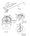
- FIGS. 9A-9Dare schematic drawings of the system implanted in a patient.
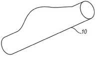
- the implantable device system of the preferred embodimentsincludes a guide tube 10 , a first electrical subsystem 12 , and a second electrical subsystem 14 .
- the first electrical subsystem 12is connected to the second electrical subsystem 14 .
- the guide tube 10functions to facilitate the insertion of at least one first electrical subsystem 12 into tissue by preventing buckling and maintaining a generally straight trajectory through the tissue, functions to allow the first electrical subsystem(s) 12 to move freely with the tissue (i.e. not being rigidly constrained), and functions to allow the placement of the first electrical subsystem 12 without disconnecting the second electrical subsystem 14 .
- the implantable device systemmay be implanted into the brain, spinal cord, peripheral nerve, muscle, or any other suitable anatomical location.
- the guide tube 10 of the systemmay be alternatively used in any suitable environment and for any suitable reason.
- the guide tube 10 of the preferred embodimentsfunctions to facilitate the insertion of at least one first electrical subsystem 12 , functions to allow the first electrical subsystem(s) 12 to move freely with the tissue (i.e. not being rigidly constrained), and functions to allow the placement of the first electrical subsystem 12 without disconnecting the second electrical subsystem 14 . Therefore, the guide tube preferably operates in the following modes: active mode, during which the guide tube is rigid in the axial direction and facilitates insertion of the first electrical subsystem into tissue, and inactive mode, during which the guide tube allows the first electrical subsystem to move freely with the tissue.
- the guide tube 10is preferably made of a rigid material, which can be inserted into tissue or other substances without buckling and can maintain a generally straight trajectory through the tissue.
- the materialmay be uniformly rigid, or rigid only in a particular direction (such as the axial direction).
- the materialis preferably plastic such as a medical grade plastic, but may alternatively be any suitable material such as metal or a combination of materials.
- the guide tube 10may further include a sharpened end adapted to penetrate the tissue and aid in the insertion of the guide tube 10 into the tissue.
- the guide tube 10may also include alignment and or fixation features to facilitate positioning and stabilizing the first electrical subsystem 12 in the tissue, particularly during removal of the guide tube.
- the transition of the guide tube between active mode and inactive modepreferably occurs in one of several variations.
- the guide tube 10is adapted to be removable from the system of electrical subsystems.
- the guide tube 10is adapted to remain with the system of electrical subsystems.
- the guide tube 10is preferably adapted in one of the several following variations, the guide tube 10 may be adapted in any suitable fashion or combination thereof to allow the transition of the guide tube between active mode and inactive mode such that the first electrical subsystem 12 to moves freely with the tissue, following the placement of the first electrical subsystem 12 , without disconnecting the second electrical subsystem 14 .
- the guide tube 10 of the first variationdefines a slit 18 , which functions to allow the guide tube to be removed over a portion of the system.
- the slit 18preferably does not prevent the guide tube 10 from maintaining rigidity as the guide tube 10 is inserted.
- a cable connecting the first electrical subsystem 12 and the second electrical subsystem 14 of the implantable device systemslides through the slit 18 , but any suitably thin portion of the implantable device system may slide through the slit 18 .
- the slitpreferably is a linear slit 18 or 18 ′′, as shown in FIGS. 2 and 4 respectively, which runs generally perpendicularly to the end of the guide tube.
- the slitmay alternatively be a spiral slit 18 ′, as shown in FIG. 3 , and may run at any suitable angle to the end of the guide tube 10 .
- the guide tube 10may define a plurality of perforations 22 , which function to allow the guide tube to be removed over a portion of the system.
- the perforations 22may supplement or replace the slit 18 of the first variation.
- the portion of the systemwill apply a generally radial force to the guide tube 10 , which will cause the perforations 22 to uncouple, creating an opening or a slit, and allow the guide tube 10 to be removed.
- There are preferably two perforations 22such that the guide tube 10 is uncoupled into two portions.
- the two portionsmay be generally equal halves, or one portion may be larger than the other.
- the perforations 22may run a portion of the guide tube 10 (as shown in FIG. 4 ), but may alternatively run the length of the guide tube 10 (perforations 22 ′ as shown in FIG. 5 ).
- the perforations 22are preferably linear and run generally perpendicularly to the end of the guide tube.
- the perforations 22may alternatively be any suitable geometry and run at any suitable angle to the end of the guide tube 10 .
- the guide tube 10is made of a brittle material that functions to crack and widen as the guide tube is moved over a portion of the system.
- the brittle materialwill not prevent the guide tube 10 from maintaining rigidity as the guide tube 10 is inserted.
- the materialis preferably adapted to crack in response to a force in the radial direction, while allowing the guide tube 10 to maintain rigidity in the axial direction.
- the portion of the systemwill apply a generally radial force to the guide tube 10 , which will cause the material to crack, creating an opening or a slit, and allow the guide tube 10 to be removed.
- the guide tube 10may be entirely made of the brittle material adapted to crack in response to a force in the radial direction and to rigid in the axial direction or a portion of the guide tube may be the brittle material while the remainder is conventional guide tube material.
- the brittle materialruns the length of the guide tube 10 , but may alternatively run any suitable portion of the length of the guide tube 10 .
- the portion of brittle materialpreferably runs generally perpendicularly to the end of the guide tube, but may alternatively be any suitable geometry and run at any suitable angle to the end of the guide tube 10 .
- the guide tube 10is adapted to break open, or at least expand its diameter to allow the removal of the guide tube 10 over the second electrical subsystem 14 .
- the guide tube 10is preferably adapted to break open, or at least expand its diameter in one of several versions.
- the first three versionsare similar to the first three versions of the first variation of the guide tube 10 , as shown in FIGS. 2-5 , except that the guide tube 10 is made from a material that can be opened or expanded in the radial direction to allow the guide tube 10 to be removed over the second electrical subsystem 14 .
- the guide tube 10is preferably made of a flexible material that functions to widen as the guide tube is moved over the second electrical subsystem 14 of the system.
- the flexible materialwill not prevent the guide tube 10 from maintaining rigidity as the guide tube 10 is inserted.
- the materialis preferably adapted to be flexible in the radial direction, while allowing the guide tube 10 to maintain rigidity in the axial direction.
- the portion of the systemwill apply a generally radial force to the guide tube 10 , which will cause the material of the guide tube 10 to widen and allow the guide tube 10 to be removed.
- the guide tube 10may be entirely made of an anisotropic material adapted to be flexible in the radial direction and rigid in the axial direction, a portion of the guide tube may be the anisotropic material while the remainder is conventional guide tube material, or a portion of the guide tube may be flexible material while the remainder is conventional guide tube material.
- the flexible or partially flexible materialruns the length of the guide tube 10 , but may alternatively run any suitable portion of the length of the guide tube 10 .
- the portion of flexible materialpreferably runs generally perpendicularly to the end of the guide tube, but may alternatively be any suitable geometry and run at any suitable angle to the end of the guide tube 10 .
- the guide tube 10includes a flexible material and splines 24 that are rigid in the axial direction, which functions to widen as the guide tube is moved over a portion of the system.
- the splines 24will allow the guide tube 10 to maintain rigidity as the guide tube 10 is inserted.
- the portion of the systemwill apply a generally radial force to the guide tube 10 , which will cause the splines 24 to move apart and the material of the guide tube 10 to flex, widening the diameter of the guide tube 10 , allowing the guide tube 10 to be removed.
- the guide tube 10may include the splines 24 alone, and not further include a flexible material or only include the flexible material along a portion of the splines 24 .
- the splines 24are preferably strips of any suitable width and thickness and preferably run along the length of the guide tube 10 and run generally perpendicularly to the end of the guide tube.
- the splines 24may alternatively be any suitable geometry, run any suitable portion of the length of the guide tube 10 , and run at any suitable angle to the end of the guide tube 10 .
- the splines 24are preferably rigid, or may alternatively be flexible in the radial direction and rigid in the axial direction.
- the splines 24may alternatively run circumferentially around the guide tube 10 or spiral around the guide tube 10 , such that there are multiple circular splines, or a spring, stacked along the length of the guide tube.
- the circular splinespreferably expand in the radial direction and due to the stacking, would be rigid in the axial direction.
- the guide tube 10 of the third variationis adapted to remain with the implanted system of electrical subsystems.
- the guide tube 10is preferably adapted to be resorbable into the tissue after a period of time.
- the guide tube 10 in this variationis preferably made from a material that is resorbable such as polyglycolide or polylactide, but may alternatively be made from any suitable bioresorbable material.
- the guide tube 10includes a flexible material and splines 24 that are rigid in the axial direction.
- the flexible material and splines 24will not prevent the guide tube 10 from maintaining rigidity as the guide tube 10 is inserted.
- the splines 24are preferably strips of any suitable width and thickness and preferably run along the length of the guide tube 10 and run generally perpendicularly to the end of the guide tube.
- the splines 24are preferably rigid.
- the splines 24may alternatively be any suitable geometry, run any suitable portion of the length of the guide tube 10 , and run at any suitable angle to the end of the guide tube 10 .
- the splines 24may alternatively run circumferentially around the guide tube 10 or spiral around the guide tube 10 , such that there are multiple circular splines 24 , or a spring, stacked along the length of the guide tube.
- the flexible guide tube 10may remain implanted, while the splines 24 are removed.
- the first electrical subsystem 12 of the preferred embodimentsfunctions to interface with the tissue, or any other suitable substance, within which it has been implanted.
- the first electrical subsystem 12may include multiple different electrical subsystems or a plurality of the same subsystems. As shown in FIG. 8 , the first electrical subsystem 12 may include a plurality of electrical subsystems and the guide tube 10 may be adapted to guide multiple first electrical subsystems 12 .
- the first electrical subsystem 12is preferably at least one of several versions or any combination thereof.
- the first electrical subsystem 12is a multi-banded cylindrical electrode with a linear arrangement of four equally spaced cylindrical electrodes, which can be used in monopolar or bipolar modes to deliver electrical stimulation to the surrounding tissue.
- the electrodescan deliver approximately spherical potential fields from separate locations along the cylindrical carrier.
- the first electrical subsystem 12is a neural interface electrode array.
- the electrode arraypreferably has a plurality of electrode sites, and more preferably a plurality of electrode sites that is more than 4.
- the neural interface electrode arrayis adapted to provide dynamic tunable electrical stimulation ranging from stimulation with macroscale specificity to microscale directional patterning.
- the electrode arrayis preferably adapted to optimally sample (record) and/or selectively activate (stimulate) neural populations.
- the plurality of electrode sitescan be tuned for recording, stimulation, or any combination thereof. Additionally, at least two electrode sites may be grouped to form a larger composite site that enables tuning the neural interface region for recording and/or stimulation.
- the neural interface electrode arrayis preferably made from a thin-film polymer substrate such that there is high density electrode sites at a first end of the array (the distal end) and bonding regions at a second end of the array (the proximal end).
- the polymer substrateis preferably parylene or some combination of parylene and inorganic dielectrics, but may alternatively be made out of any suitable material.
- the distal end of the arrayis preferably coupled to a carrier to provide structural support.
- the electrode arraymay further include fluidic channels providing the capability to deliver therapeutic drugs, drugs to inhibit biologic response to the implant, or any other suitable fluid.
- the first electrical subsystem 12may be adapted for long term implantation as in the first two variations, or alternatively may be adapted for short-term intraoperative use as in the following third variation.
- the first electrical subsystem 12is a mapping electrode system, which is adapted to perform clinical deep brain electrophysiological mapping for use in neurosurgerical applications. More specifically, the mapping electrode system is preferably adapted to perform simultaneous multichannel neural recording from precisely known locations along the deep microelectrode track.
- the mapping electrodemay further have extended functionality such as multichannel recording and/or stimulation or fluid delivery.
- the first electrical subsystem 12is preferably one of these several versions, the first electrical subsystem 12 may be any suitable element or combination of elements to perform the desired functions.
- the second electrical subsystem 14 of the preferred embodimentsfunctions to operate with the first electrical subsystem 12 .
- the second electrical subsystem 14may include multiple different electrical subsystems or a plurality of the same subsystems. Additionally, the guide tube 10 may be adapted to be removable over multiple second electrical subsystems 14 .
- the second electrical subsystemis preferably at least one of several versions or any combination thereof.
- the second electrical subsystem 14is a suitable electronic subsystem to operate with an implantable neural interface.
- the second electrical subsystem 14may be a printed circuit board with or without on-board integrated circuits and/or on-chip circuitry for signal conditioning and/or stimulus generation, an Application Specific Integrated Circuit (ASIC), a multiplexer chip, a buffer amplifier, an electronics interface, an implantable pulse generator, an implantable rechargeable battery, integrated electronics for either real-time signal processing of the input (recorded) or output (stimulation) signals, integrated electronics for control of the fluidic components, any other suitable electrical subsystem, or any combination thereof.
- ASICApplication Specific Integrated Circuit
- the second electrical subsystem 14is preferably one of these several subsystems, the second electrical subsystem 14 may be any suitable element or combination of elements to operate any suitable first electrical subsystem 12 .
- the systemmay further include a connector such as a cable 16 that functions to couple the first electrical subsystem 12 to the second electrical subsystem 14 .
- the cable 16is preferably one of several versions. As shown in FIGS. 1 and 8 , the cable is preferably a flexible ribbon cable.
- the ribbon cableis preferably a polymer ribbon cable, but may alternatively be any other suitable ribbon cable.
- the cable 16may alternatively be any suitable element to couple the first electrical subsystem 12 to the second electrical subsystem 14 , such as wires, conductive interconnects, etc.
- the ribbon cablemay be encased in silicone or any other suitable material. In some situations, the electrical subsystem may have multiple ribbon cables.
- multiple ribbon cableswould be physically attached along their entire length, using a suitable adhesive such as medical grade adhesive or any other suitable connection mechanism.
- the cableis preferably connected to the electrical subsystems through ball bonds, ball bond, or any other suitable connection mechanisms.
- the cable 16may alternatively be seamlessly manufactured with the first and or second electrical subsystem.
- the cable 16may further include fluidic channels adapted to deliver therapeutic drugs, drugs to inhibit biologic response to the implant, or any other suitable fluid.
- a method of implanting an implant and its corresponding electrical componentspreferably includes any combination of the following steps (or any other suitable steps):
- the preferred embodimentsinclude every combination and permutation of the various guide tubes 10 , the various expansion elements, the various electrical subsystems, the various cables, and the various methods of use.
Landscapes
- Health & Medical Sciences (AREA)
- Neurology (AREA)
- Neurosurgery (AREA)
- Engineering & Computer Science (AREA)
- Veterinary Medicine (AREA)
- Psychology (AREA)
- Public Health (AREA)
- Biomedical Technology (AREA)
- Nuclear Medicine, Radiotherapy & Molecular Imaging (AREA)
- Radiology & Medical Imaging (AREA)
- Life Sciences & Earth Sciences (AREA)
- Animal Behavior & Ethology (AREA)
- General Health & Medical Sciences (AREA)
- Heart & Thoracic Surgery (AREA)
- Cardiology (AREA)
- Orthopedic Medicine & Surgery (AREA)
- Child & Adolescent Psychology (AREA)
- Developmental Disabilities (AREA)
- Hospice & Palliative Care (AREA)
- Psychiatry (AREA)
- Electrotherapy Devices (AREA)
Abstract
Description
- S110, which includes attaching a cranial chamber to the skull (preferably in a cranial burr-hole) of a patient (
FIG. 9A ); - S120, which includes implanting, through the
guide tube 10, a firstelectrical subsystem 12 which is preferably a mapping electrode system (FIGS. 9B and 9C ); - removing, through the
guide tube 10, the mapping electrode system following microelectrode recording; - S130, which includes implanting, through the
guide tube 10, a firstelectrical subsystem 12 which is preferably a neural interface electrode array coupled via acable 16 to a second electrical subsystem14 (FIGS. 9B and 9C ); - S140, which includes removing the guide tube from the system (
FIG. 9D ); - S150, which includes placing the second
electrical subsystem 14 within the chamber (FIG. 9B ); and - sealing the electrical subsystems within the chamber.
- S110, which includes attaching a cranial chamber to the skull (preferably in a cranial burr-hole) of a patient (
Claims (7)
Priority Applications (2)
| Application Number | Priority Date | Filing Date | Title |
|---|---|---|---|
| US12/253,796US8224417B2 (en) | 2007-10-17 | 2008-10-17 | Guide tube for an implantable device system |
| US13/491,358US8805468B2 (en) | 2007-10-17 | 2012-06-07 | Guide tube for an implantable device system |
Applications Claiming Priority (2)
| Application Number | Priority Date | Filing Date | Title |
|---|---|---|---|
| US98065007P | 2007-10-17 | 2007-10-17 | |
| US12/253,796US8224417B2 (en) | 2007-10-17 | 2008-10-17 | Guide tube for an implantable device system |
Related Child Applications (1)
| Application Number | Title | Priority Date | Filing Date |
|---|---|---|---|
| US13/491,358ContinuationUS8805468B2 (en) | 2007-10-17 | 2012-06-07 | Guide tube for an implantable device system |
Publications (2)
| Publication Number | Publication Date |
|---|---|
| US20090187196A1 US20090187196A1 (en) | 2009-07-23 |
| US8224417B2true US8224417B2 (en) | 2012-07-17 |
Family
ID=40877049
Family Applications (2)
| Application Number | Title | Priority Date | Filing Date |
|---|---|---|---|
| US12/253,796Active2030-08-13US8224417B2 (en) | 2007-10-17 | 2008-10-17 | Guide tube for an implantable device system |
| US13/491,358ActiveUS8805468B2 (en) | 2007-10-17 | 2012-06-07 | Guide tube for an implantable device system |
Family Applications After (1)
| Application Number | Title | Priority Date | Filing Date |
|---|---|---|---|
| US13/491,358ActiveUS8805468B2 (en) | 2007-10-17 | 2012-06-07 | Guide tube for an implantable device system |
Country Status (1)
| Country | Link |
|---|---|
| US (2) | US8224417B2 (en) |
Cited By (15)
| Publication number | Priority date | Publication date | Assignee | Title |
|---|---|---|---|---|
| US20120184837A1 (en)* | 2011-01-14 | 2012-07-19 | Sapiens Steering Brain Stimulation B.V. | Brain Mapping Probe |
| US8805468B2 (en)* | 2007-10-17 | 2014-08-12 | Neuronexus Technologies, Inc. | Guide tube for an implantable device system |
| US8958890B2 (en) | 2012-01-17 | 2015-02-17 | Neuronexus Technologies, Inc. | Implantable neural interface device with a deformable carrier |
| US20170251976A1 (en)* | 2014-08-27 | 2017-09-07 | Neuronano Ab | Method of implantation of a medical device into neural tissue |
| US10065031B2 (en) | 2014-08-27 | 2018-09-04 | Aleva Neurotherapeutics | Deep brain stimulation lead |
| US10166392B2 (en) | 2008-07-30 | 2019-01-01 | Ecole Polytechnique Federale De Lausanne | Apparatus and method for optimized stimulation of a neurological target |
| US10201707B2 (en) | 2014-08-27 | 2019-02-12 | Aleva Neurotherapeutics | Treatment of autoimmune diseases with deep brain stimulation |
| US10252024B2 (en) | 2016-04-05 | 2019-04-09 | Stryker Corporation | Medical devices and methods of manufacturing same |
| US10406350B2 (en) | 2008-11-12 | 2019-09-10 | Ecole Polytechnique Federale De Lausanne | Microfabricated neurostimulation device |
| US10695556B2 (en) | 2010-04-01 | 2020-06-30 | Ecole Polytechnique Federale De Lausanne | Device for interacting with neurological tissue and methods of making and using the same |
| US10702692B2 (en) | 2018-03-02 | 2020-07-07 | Aleva Neurotherapeutics | Neurostimulation device |
| US20210045690A1 (en)* | 2018-03-01 | 2021-02-18 | Universitat Basel Vizerektorat Forschung | Neural probe for electrostimulation or recording and fabrication process for such a probe |
| US10966620B2 (en) | 2014-05-16 | 2021-04-06 | Aleva Neurotherapeutics Sa | Device for interacting with neurological tissue and methods of making and using the same |
| US11273295B2 (en) | 2018-04-19 | 2022-03-15 | Spiral Therapeutics, Inc. | Inner ear drug delivery devices and methods of use |
| US11311718B2 (en) | 2014-05-16 | 2022-04-26 | Aleva Neurotherapeutics Sa | Device for interacting with neurological tissue and methods of making and using the same |
Families Citing this family (29)
| Publication number | Priority date | Publication date | Assignee | Title |
|---|---|---|---|---|
| WO2005039696A1 (en)* | 2003-10-21 | 2005-05-06 | The Regents Of The University Of Michigan | Intracranial neural interface system |
| WO2006138358A2 (en) | 2005-06-14 | 2006-12-28 | The Regents Of The University Of Michigan Technology Management Office | Flexible polymer microelectrode with fluid delivery capability and methods for making same |
| WO2007042999A2 (en) | 2005-10-07 | 2007-04-19 | Neuronexus Technologies | Modular multichannel microelectrode array and methods of making same |
| WO2007089738A2 (en)* | 2006-01-26 | 2007-08-09 | The Regents Of The University Of Michigan | Microelectrode with laterally extending platform for reduction of tissue encapsulation |
| US8731673B2 (en)* | 2007-02-26 | 2014-05-20 | Sapiens Steering Brain Stimulation B.V. | Neural interface system |
| WO2009052425A1 (en) | 2007-10-17 | 2009-04-23 | Neuronexus Technologies | Implantable device including a resorbable carrier |
| US8565894B2 (en) | 2007-10-17 | 2013-10-22 | Neuronexus Technologies, Inc. | Three-dimensional system of electrode leads |
| US8498720B2 (en) | 2008-02-29 | 2013-07-30 | Neuronexus Technologies, Inc. | Implantable electrode and method of making the same |
| US9289142B2 (en) | 2008-03-24 | 2016-03-22 | Neuronexus Technologies, Inc. | Implantable electrode lead system with a three dimensional arrangement and method of making the same |
| US20090240314A1 (en)* | 2008-03-24 | 2009-09-24 | Kong K C | Implantable electrode lead system with a three dimensional arrangement and method of making the same |
| US8332046B2 (en) | 2009-10-16 | 2012-12-11 | Neuronexus Technologies, Inc. | Neural interface system |
| CN102686147B (en)* | 2009-11-05 | 2016-01-20 | 格雷特巴奇有限公司 | waveguide neural interface device |
| CA2782710C (en) | 2009-12-01 | 2019-01-22 | Ecole Polytechnique Federale De Lausanne | Microfabricated neurostimulation device and methods of making and using the same |
| US9155861B2 (en) | 2010-09-20 | 2015-10-13 | Neuronexus Technologies, Inc. | Neural drug delivery system with fluidic threads |
| WO2012158834A1 (en)* | 2011-05-16 | 2012-11-22 | Second Sight Medical Products, Inc. | Cortical interface with an electrode array divided into separate fingers and/or with a wireless transceiver |
| US9413896B2 (en) | 2012-09-14 | 2016-08-09 | The Spectranetics Corporation | Tissue slitting methods and systems |
| US10835279B2 (en) | 2013-03-14 | 2020-11-17 | Spectranetics Llc | Distal end supported tissue slitting apparatus |
| US10194978B2 (en)* | 2014-06-13 | 2019-02-05 | Medtronic Cryocath Lp | Supporting catheter for use for phrenic nerve pacing |
| CN104055510B (en)* | 2014-06-26 | 2016-06-01 | 浙江大学 | Based on the Wearable rat olfactory nerve signal supervisory instrument of cableless communication |
| US9403011B2 (en) | 2014-08-27 | 2016-08-02 | Aleva Neurotherapeutics | Leadless neurostimulator |
| US9364659B1 (en)* | 2015-04-27 | 2016-06-14 | Dantam K. Rao | Smart lead for deep brain stimulation |
| CA3041999A1 (en) | 2016-10-31 | 2018-05-03 | The Alfred E. Mann Foundation For Scientific Research | Nerve cuff electrodes fabricated using over-molded lcp substrates |
| CA3193733A1 (en) | 2020-09-02 | 2022-03-10 | The Alfred E. Mann Foundation For Scientific Research | Electrode leads having multi-application nerve cuffs and associated systems and methods |
| AU2022249112A1 (en) | 2021-03-30 | 2023-10-12 | The Alfred E. Mann Foundation For Scientific Research | Electrode leads having nerve cuffs and associated systems |
| EP4366818A1 (en) | 2021-07-09 | 2024-05-15 | The Alfred E. Mann Foundation for Scientific Research | Electrode leads having multi-application helical nerve cuffs and associated systems and methods |
| US12296172B2 (en) | 2022-02-01 | 2025-05-13 | The Alfred E. Mann Foundation For Scientific Research | Electrode leads having nerve contact elements with coil contacts and associated systems and methods |
| CN115227254B (en)* | 2022-07-25 | 2024-06-25 | 武汉衷华脑机融合科技发展有限公司 | Composite microneedle structure and nerve microelectrode |
| CN115251931B (en)* | 2022-07-25 | 2024-07-23 | 武汉衷华脑机融合科技发展有限公司 | Composite microneedle structure and preparation method thereof |
| CN115281682B (en)* | 2022-07-25 | 2024-06-14 | 武汉衷华脑机融合科技发展有限公司 | Composite microneedle structure and preparation method thereof |
Citations (106)
| Publication number | Priority date | Publication date | Assignee | Title |
|---|---|---|---|---|
| US3847687A (en) | 1972-11-15 | 1974-11-12 | Motorola Inc | Methods of forming self aligned transistor structure having polycrystalline contacts |
| US3921916A (en) | 1974-12-31 | 1975-11-25 | Ibm | Nozzles formed in monocrystalline silicon |
| US4141365A (en)* | 1977-02-24 | 1979-02-27 | The Johns Hopkins University | Epidural lead electrode and insertion needle |
| US4166469A (en)* | 1977-12-13 | 1979-09-04 | Littleford Philip O | Apparatus and method for inserting an electrode |
| US4306562A (en)* | 1978-12-01 | 1981-12-22 | Cook, Inc. | Tear apart cannula |
| US4455192A (en) | 1981-05-07 | 1984-06-19 | Fuji Xerox Company, Ltd. | Formation of a multi-nozzle ink jet |
| US4461304A (en) | 1979-11-05 | 1984-07-24 | Massachusetts Institute Of Technology | Microelectrode and assembly for parallel recording of neurol groups |
| US4465482A (en)* | 1979-03-07 | 1984-08-14 | Gerhard Hug Gmbh | Suction drainage tube |
| US4762135A (en) | 1985-08-30 | 1988-08-09 | Puije P D V D | Cochlea implant |
| US4886065A (en)* | 1988-08-08 | 1989-12-12 | California Institute Of Technology | In vivo electrode implanting system |
| US4904237A (en) | 1988-05-16 | 1990-02-27 | Janese Woodrow W | Apparatus for the exchange of cerebrospinal fluid and a method of treating brain and spinal cord injuries |
| US5108819A (en) | 1990-02-14 | 1992-04-28 | Eli Lilly And Company | Thin film electrical component |
| US5180376A (en)* | 1990-05-01 | 1993-01-19 | Cathco, Inc. | Non-buckling thin-walled sheath for the percutaneous insertion of intraluminal catheters |
| US5207709A (en) | 1991-11-13 | 1993-05-04 | Picha George J | Implant with textured surface |
| US5215088A (en) | 1989-11-07 | 1993-06-01 | The University Of Utah | Three-dimensional electrode device |
| US5308442A (en) | 1993-01-25 | 1994-05-03 | Hewlett-Packard Company | Anisotropically etched ink fill slots in silicon |
| US5322064A (en) | 1991-02-15 | 1994-06-21 | Lundquist Ingemar H | Torquable catheter and method |
| US5385635A (en) | 1993-11-01 | 1995-01-31 | Xerox Corporation | Process for fabricating silicon channel structures with variable cross-sectional areas |
| US5390671A (en)* | 1994-03-15 | 1995-02-21 | Minimed Inc. | Transcutaneous sensor insertion set |
| US5409469A (en)* | 1993-11-04 | 1995-04-25 | Medtronic, Inc. | Introducer system having kink resistant splittable sheath |
| US5496360A (en) | 1994-04-12 | 1996-03-05 | Ventritex, Inc. | Implantable cardiac electrode with rate controlled drug delivery |
| US5515848A (en) | 1991-10-22 | 1996-05-14 | Pi Medical Corporation | Implantable microelectrode |
| US5573520A (en)* | 1991-09-05 | 1996-11-12 | Mayo Foundation For Medical Education And Research | Flexible tubular device for use in medical applications |
| US5585827A (en) | 1993-10-29 | 1996-12-17 | Sony Corporation | Printer head |
| US5588597A (en) | 1993-09-03 | 1996-12-31 | Microparts Gmbh | Nozzle plate for a liquid jet print head |
| US5720099A (en) | 1996-01-31 | 1998-02-24 | Cochlear Limited | Thin film fabrication technique for implantable electrodes |
| US5744958A (en) | 1995-11-07 | 1998-04-28 | Iti Medical Technologies, Inc. | Instrument having ultra-thin conductive coating and method for magnetic resonance imaging of such instrument |
| US5800535A (en) | 1994-02-09 | 1998-09-01 | The University Of Iowa Research Foundation | Wireless prosthetic electrode for the brain |
| US5843150A (en) | 1997-10-08 | 1998-12-01 | Medtronic, Inc. | System and method for providing electrical and/or fluid treatment within a patient's brain |
| US5927277A (en) | 1995-04-28 | 1999-07-27 | Medtronic, Inc. | Method and apparatus for securing probes within a burr hole |
| US5938694A (en) | 1993-11-10 | 1999-08-17 | Medtronic Cardiorhythm | Electrode array catheter |
| US5975085A (en) | 1997-05-01 | 1999-11-02 | Medtronic, Inc. | Method of treating schizophrenia by brain stimulation and drug infusion |
| US5989445A (en) | 1995-06-09 | 1999-11-23 | The Regents Of The University Of Michigan | Microchannel system for fluid delivery |
| US6006124A (en) | 1998-05-01 | 1999-12-21 | Neuropace, Inc. | Means and method for the placement of brain electrodes |
| US6016449A (en) | 1997-10-27 | 2000-01-18 | Neuropace, Inc. | System for treatment of neurological disorders |
| US6044304A (en) | 1998-04-29 | 2000-03-28 | Medtronic, Inc. | Burr ring with integral lead/catheter fixation device |
| US6132456A (en)* | 1998-03-10 | 2000-10-17 | Medtronic, Inc. | Arrangement for implanting an endocardial cardiac lead |
| US6181569B1 (en) | 1999-06-07 | 2001-01-30 | Kishore K. Chakravorty | Low cost chip size package and method of fabricating the same |
| WO2001012115A1 (en) | 1999-08-18 | 2001-02-22 | Epic Biosonics Inc. | Modiolar hugging electrode array |
| US6205361B1 (en) | 1998-02-10 | 2001-03-20 | Advanced Bionics Corporation | Implantable expandable multicontact electrodes |
| US6228111B1 (en) | 1995-09-27 | 2001-05-08 | Bionx Implants Oy | Biodegradable implant manufactured of polymer-based material and a method for manufacturing the same |
| US6324433B1 (en) | 2000-01-20 | 2001-11-27 | Electrocare Technologies, Llc | Electrode-lead coupling skull mounted port assembly |
| US6325797B1 (en) | 1999-04-05 | 2001-12-04 | Medtronic, Inc. | Ablation catheter and method for isolating a pulmonary vein |
| US20010049499A1 (en)* | 1999-12-30 | 2001-12-06 | Lui Chun Kee | Splittable medical valve |
| US20020052610A1 (en)* | 2000-04-07 | 2002-05-02 | Skakoon James G. | Deep organ access device and method |
| WO2002036002A1 (en) | 2000-11-01 | 2002-05-10 | 3M Innovative Properties Company | Electrical sensing and/or signal application device |
| WO2002041666A1 (en) | 2000-11-14 | 2002-05-23 | Cochlear Limited | Apparatus for delivery of pharmaceuticals to the cochlea |
| US6430443B1 (en) | 2000-03-21 | 2002-08-06 | Manuel L. Karell | Method and apparatus for treating auditory hallucinations |
| US20020183817A1 (en) | 2000-12-07 | 2002-12-05 | Paul Van Venrooij | Directional brain stimulation and recording leads |
| WO2002096482A2 (en) | 2001-05-30 | 2002-12-05 | Innersea Technology | Implantable devices having a liquid crystal polymer substrate |
| US20020198446A1 (en) | 2001-06-21 | 2002-12-26 | Hill Norman M. | Multi-channel structurally robust brain probe and method of making the same |
| US20030093129A1 (en) | 2001-10-29 | 2003-05-15 | Nicolelis Miguel A.L. | Closed loop brain machine interface |
| US20030100823A1 (en) | 2000-03-29 | 2003-05-29 | Daryl Kipke | Device for creating a neural interface and method for making same |
| US20030114906A1 (en) | 2001-12-17 | 2003-06-19 | Theracardia, Inc. | Apparatus and methods for deploying cardiac electrodes |
| US6600231B2 (en) | 2000-05-11 | 2003-07-29 | Mitutoyo Corporation | Functional device unit and method of producing the same |
| US6618623B1 (en) | 2000-11-28 | 2003-09-09 | Neuropace, Inc. | Ferrule for cranial implant |
| US20030187461A1 (en)* | 1999-08-10 | 2003-10-02 | Chin Albert K. | Releasable guide and method for endoscopic cardiac lead placement |
| US20040006264A1 (en) | 2001-11-20 | 2004-01-08 | Mojarradi Mohammad M. | Neural prosthetic micro system |
| US20040102828A1 (en) | 2002-11-27 | 2004-05-27 | Lowry David Warren | Methods and systems employing intracranial electrodes for neurostimulation and/or electroencephalography |
| US20040106169A1 (en) | 2002-12-02 | 2004-06-03 | Evans Daron G. | System and method for metabolyte neuronal network analysis |
| US20040199235A1 (en) | 2001-09-30 | 2004-10-07 | Imad Younis | Electrode system for neural applications |
| US6834200B2 (en) | 2000-10-19 | 2004-12-21 | Philadelphia, Health & Education Corporation | Ceramic based multi-site electrode arrays and methods for their production |
| US20050004627A1 (en) | 2001-10-26 | 2005-01-06 | Peter Gibson | Auditory midbrain implant |
| US20050021116A1 (en) | 2003-07-21 | 2005-01-27 | Jiping He | Electrode for implant in live tissue with flexible region to accommodate micro-movement |
| US20050021117A1 (en) | 2003-07-21 | 2005-01-27 | Jiping He | Flexible integrated head-stage for neural interface |
| US6878643B2 (en) | 2002-12-18 | 2005-04-12 | The Regents Of The University Of California | Electronic unit integrated into a flexible polymer body |
| WO2005039696A1 (en) | 2003-10-21 | 2005-05-06 | The Regents Of The University Of Michigan | Intracranial neural interface system |
| US20050137647A1 (en) | 2003-12-22 | 2005-06-23 | Scimed Life Systems, Inc. | Method of intravascularly delivering stimulation leads into direct contact with tissue |
| US20050222647A1 (en) | 2004-03-30 | 2005-10-06 | Wahlstrand Carl D | Lead electrode for use in an MRI-safe implantable medical device |
| US7004948B1 (en) | 2001-01-31 | 2006-02-28 | Advanced Bionics Corporation | Cranial sealing plug |
| US7006859B1 (en) | 2002-07-20 | 2006-02-28 | Flint Hills Scientific, L.L.C. | Unitized electrode with three-dimensional multi-site, multi-modal capabilities for detection and control of brain state changes |
| US7010356B2 (en) | 2001-10-31 | 2006-03-07 | London Health Sciences Centre Research Inc. | Multichannel electrode and methods of using same |
| US7011680B2 (en) | 2001-05-02 | 2006-03-14 | Inflow Dynamics Inc. | Stent device and method |
| US20060122677A1 (en) | 2004-10-21 | 2006-06-08 | Vardiman Arnold B | Various apparatus and methods for deep brain stimulating electrodes |
| US20060173263A1 (en) | 2003-02-04 | 2006-08-03 | Jiping He | Neural interface assembly and method for making and implanting the same |
| US7089059B1 (en) | 2000-11-03 | 2006-08-08 | Pless Benjamin D | Predicting susceptibility to neurological dysfunction based on measured neural electrophysiology |
| US20060247749A1 (en) | 2005-05-02 | 2006-11-02 | Advanced Bionics Corporation | Compliant stimulating electrodes and leads and methods of manufacture and use |
| US20060258951A1 (en) | 2005-05-16 | 2006-11-16 | Baxano, Inc. | Spinal Access and Neural Localization |
| US20060276866A1 (en) | 2005-06-02 | 2006-12-07 | Mccreery Douglas B | Microelectrode array for chronic deep-brain microstimulation for recording |
| US20060282014A1 (en) | 2005-06-14 | 2006-12-14 | The Regents Of The University Of Michigan | Flexible polymer microelectrode with fluid delivery capability and methods for making same |
| US7181288B1 (en) | 2002-06-24 | 2007-02-20 | The Cleveland Clinic Foundation | Neuromodulation device and method of using the same |
| US20070073130A1 (en) | 2003-11-06 | 2007-03-29 | Dudley Finch | Shape-memory polymer coated electrodes |
| US20070123765A1 (en) | 2005-10-07 | 2007-05-31 | Hetke Jamille F | Modular multichannel microelectrode array and methods of making same |
| US20070135885A1 (en) | 2005-12-08 | 2007-06-14 | Cochlear Limited | Flexible electrode assembly having variable pitch electrodes for a stimulating medical device |
| US7343205B1 (en)* | 2002-08-20 | 2008-03-11 | Boston Scientific Neuromodulation Corp. | System and method for insertion of a device into the brain |
| US20080132970A1 (en)* | 2006-12-05 | 2008-06-05 | Giancarlo Barolat | Method and system for treatment of intractable scrotal and/or testicular pain |
| US20080208283A1 (en) | 2007-02-26 | 2008-08-28 | Rio Vetter | Neural Interface System |
| US20080255439A1 (en) | 2004-06-01 | 2008-10-16 | California Institute Of Technology | Microfabricated Neural Probes and Methods of Making Same |
| US20080262584A1 (en) | 2007-03-19 | 2008-10-23 | Bottomley Paul A | Methods and apparatus for fabricating leads with conductors and related flexible lead configurations |
| US20090099555A1 (en) | 2007-10-11 | 2009-04-16 | Ingmar Viohl | Reduction of rf induced tissue heating using conductive surface pattern |
| US20090102068A1 (en) | 2007-10-17 | 2009-04-23 | Pellinen David S | System and method to manufacture an implantable electrode |
| US20090118806A1 (en) | 2007-10-17 | 2009-05-07 | Vetter Rio J | Three-dimensional system of electrode leads |
| US20090132042A1 (en) | 2007-10-17 | 2009-05-21 | Hetke Jamille F | Implantable device including a resorbable carrier |
| US20090149934A1 (en) | 2007-12-06 | 2009-06-11 | Cardiac Pacemakers, Inc. | Implantable lead with shielding |
| US20090171421A1 (en) | 2005-10-21 | 2009-07-02 | Ergin Atalar | Mri-safe high impedance lead systems |
| US20090234426A1 (en) | 2008-02-29 | 2009-09-17 | Pellinen David S | Implantable electrode and method of making the same |
| US20090240314A1 (en) | 2008-03-24 | 2009-09-24 | Kong K C | Implantable electrode lead system with a three dimensional arrangement and method of making the same |
| US20090248118A1 (en) | 2001-12-04 | 2009-10-01 | Boston Scientific Neuromodulation Corporation | Apparatus and method for determining the relative position and orientation of neurostimulation leads |
| US20090299167A1 (en) | 2006-01-26 | 2009-12-03 | Seymour John P | Microelectrode with laterally extending platform for reduction of tissue encapsulation |
| US20090312770A1 (en) | 2008-06-12 | 2009-12-17 | Takashi Daniel Yoshida Kozai | Probe insertion device for implanting a probe into tissue |
| US20100030298A1 (en) | 2006-09-26 | 2010-02-04 | Koninklijke Philips Electronics N.V. | Tissue stimulation method and apparatus |
| US20100145422A1 (en) | 2008-11-14 | 2010-06-10 | The Regents Of The University Of Michigan | Method for manufacturing an implantable electronic device |
| US7871707B2 (en) | 2005-11-10 | 2011-01-18 | Second Sight Medical Products, Inc. | Polymer comprising silicone and metal trace |
| WO2011010257A1 (en) | 2009-07-24 | 2011-01-27 | Koninklijke Philips Electronics N.V. | Medical device for electrical stimulation |
| US7914842B1 (en) | 2006-02-10 | 2011-03-29 | Second Sight Medical Products, Inc | Method of manufacturing a flexible circuit electrode array |
| US20110093052A1 (en) | 2009-10-16 | 2011-04-21 | Anderson David J | Neural interface system |
Family Cites Families (21)
| Publication number | Priority date | Publication date | Assignee | Title |
|---|---|---|---|---|
| US2458305A (en)* | 1947-04-26 | 1949-01-04 | Richard D Sanders | Tubular article comprising rubberlike material |
| US5183464A (en)* | 1991-05-17 | 1993-02-02 | Interventional Thermodynamics, Inc. | Radially expandable dilator |
| US5395349A (en)* | 1991-12-13 | 1995-03-07 | Endovascular Technologies, Inc. | Dual valve reinforced sheath and method |
| US6090072A (en)* | 1992-10-15 | 2000-07-18 | Scimed Life Systems, Inc. | Expandable introducer sheath |
| US5713867A (en)* | 1996-04-29 | 1998-02-03 | Medtronic, Inc. | Introducer system having kink resistant splittable sheath |
| US20040102804A1 (en)* | 1999-08-10 | 2004-05-27 | Chin Albert K. | Apparatus and methods for endoscopic surgical procedures |
| US6749600B1 (en)* | 2000-11-15 | 2004-06-15 | Impulse Dynamics N.V. | Braided splittable catheter sheath |
| US7678128B2 (en)* | 2001-06-29 | 2010-03-16 | Advanced Cardiovascular Systems, Inc. | Delivery and recovery sheaths for medical devices |
| EP1418850B1 (en)* | 2001-08-01 | 2010-10-06 | Tyco Healthcare Group LP | Apparatus for providing percutaneous access and medicament to a target surgical site |
| US7588581B2 (en)* | 2002-03-26 | 2009-09-15 | Medtronic, Inc. | Placement of chronic micro-catheter device and method |
| US6939327B2 (en)* | 2002-05-07 | 2005-09-06 | Cardiac Pacemakers, Inc. | Peel-away sheath |
| US7780692B2 (en)* | 2003-12-05 | 2010-08-24 | Onset Medical Corporation | Expandable percutaneous sheath |
| WO2006041738A2 (en)* | 2004-10-04 | 2006-04-20 | Cyberkinetics Neurotechnology Systems, Inc. | Biological interface system |
| AU2006218490B2 (en)* | 2005-03-02 | 2011-02-10 | Cook Medical Technologies Llc | Introducer sheath |
| WO2008011721A1 (en) | 2006-07-28 | 2008-01-31 | Med-El Elektro-Medizinische Geräte Gesellschaft M.B.H. | Layered electrode array and cable |
| WO2008072125A1 (en) | 2006-12-13 | 2008-06-19 | Koninklijke Philips Electronics, N.V. | First time right placement of a dbs lead |
| US20090018631A1 (en)* | 2006-12-29 | 2009-01-15 | Elizabeth Ann Snoderly | Surgical insertion apparatus |
| US8012127B2 (en)* | 2007-02-28 | 2011-09-06 | Medtronic, Inc. | Systems and methods for gaining access around an implanted medical device |
| US8224417B2 (en)* | 2007-10-17 | 2012-07-17 | Neuronexus Technologies, Inc. | Guide tube for an implantable device system |
| US8632502B2 (en)* | 2008-03-27 | 2014-01-21 | Medtronic, Inc. | Anchor deployment apparatus |
| US20110218549A1 (en)* | 2010-03-05 | 2011-09-08 | Boston Scientific Neuromodulation Corporation | Systems and methods for making and using a trial stimulation system having an electrical connector disposed on a trial stimulation lead |
- 2008
- 2008-10-17USUS12/253,796patent/US8224417B2/enactiveActive
- 2012
- 2012-06-07USUS13/491,358patent/US8805468B2/enactiveActive
Patent Citations (115)
| Publication number | Priority date | Publication date | Assignee | Title |
|---|---|---|---|---|
| US3847687A (en) | 1972-11-15 | 1974-11-12 | Motorola Inc | Methods of forming self aligned transistor structure having polycrystalline contacts |
| US3921916A (en) | 1974-12-31 | 1975-11-25 | Ibm | Nozzles formed in monocrystalline silicon |
| US4141365A (en)* | 1977-02-24 | 1979-02-27 | The Johns Hopkins University | Epidural lead electrode and insertion needle |
| US4166469A (en)* | 1977-12-13 | 1979-09-04 | Littleford Philip O | Apparatus and method for inserting an electrode |
| US4306562A (en)* | 1978-12-01 | 1981-12-22 | Cook, Inc. | Tear apart cannula |
| US4465482A (en)* | 1979-03-07 | 1984-08-14 | Gerhard Hug Gmbh | Suction drainage tube |
| US4461304A (en) | 1979-11-05 | 1984-07-24 | Massachusetts Institute Of Technology | Microelectrode and assembly for parallel recording of neurol groups |
| US4455192A (en) | 1981-05-07 | 1984-06-19 | Fuji Xerox Company, Ltd. | Formation of a multi-nozzle ink jet |
| US4762135A (en) | 1985-08-30 | 1988-08-09 | Puije P D V D | Cochlea implant |
| US4904237A (en) | 1988-05-16 | 1990-02-27 | Janese Woodrow W | Apparatus for the exchange of cerebrospinal fluid and a method of treating brain and spinal cord injuries |
| US4886065A (en)* | 1988-08-08 | 1989-12-12 | California Institute Of Technology | In vivo electrode implanting system |
| US5215088A (en) | 1989-11-07 | 1993-06-01 | The University Of Utah | Three-dimensional electrode device |
| US5108819A (en) | 1990-02-14 | 1992-04-28 | Eli Lilly And Company | Thin film electrical component |
| US5180376A (en)* | 1990-05-01 | 1993-01-19 | Cathco, Inc. | Non-buckling thin-walled sheath for the percutaneous insertion of intraluminal catheters |
| US5322064A (en) | 1991-02-15 | 1994-06-21 | Lundquist Ingemar H | Torquable catheter and method |
| US5573520A (en)* | 1991-09-05 | 1996-11-12 | Mayo Foundation For Medical Education And Research | Flexible tubular device for use in medical applications |
| US5515848A (en) | 1991-10-22 | 1996-05-14 | Pi Medical Corporation | Implantable microelectrode |
| US5524338A (en) | 1991-10-22 | 1996-06-11 | Pi Medical Corporation | Method of making implantable microelectrode |
| US5207709A (en) | 1991-11-13 | 1993-05-04 | Picha George J | Implant with textured surface |
| US5308442A (en) | 1993-01-25 | 1994-05-03 | Hewlett-Packard Company | Anisotropically etched ink fill slots in silicon |
| US5588597A (en) | 1993-09-03 | 1996-12-31 | Microparts Gmbh | Nozzle plate for a liquid jet print head |
| US5585827A (en) | 1993-10-29 | 1996-12-17 | Sony Corporation | Printer head |
| US5385635A (en) | 1993-11-01 | 1995-01-31 | Xerox Corporation | Process for fabricating silicon channel structures with variable cross-sectional areas |
| US5409469A (en)* | 1993-11-04 | 1995-04-25 | Medtronic, Inc. | Introducer system having kink resistant splittable sheath |
| US5938694A (en) | 1993-11-10 | 1999-08-17 | Medtronic Cardiorhythm | Electrode array catheter |
| US5800535A (en) | 1994-02-09 | 1998-09-01 | The University Of Iowa Research Foundation | Wireless prosthetic electrode for the brain |
| US5390671A (en)* | 1994-03-15 | 1995-02-21 | Minimed Inc. | Transcutaneous sensor insertion set |
| US5496360A (en) | 1994-04-12 | 1996-03-05 | Ventritex, Inc. | Implantable cardiac electrode with rate controlled drug delivery |
| US5927277A (en) | 1995-04-28 | 1999-07-27 | Medtronic, Inc. | Method and apparatus for securing probes within a burr hole |
| US5989445A (en) | 1995-06-09 | 1999-11-23 | The Regents Of The University Of Michigan | Microchannel system for fluid delivery |
| US5992769A (en) | 1995-06-09 | 1999-11-30 | The Regents Of The University Of Michigan | Microchannel system for fluid delivery |
| US6228111B1 (en) | 1995-09-27 | 2001-05-08 | Bionx Implants Oy | Biodegradable implant manufactured of polymer-based material and a method for manufacturing the same |
| US5744958A (en) | 1995-11-07 | 1998-04-28 | Iti Medical Technologies, Inc. | Instrument having ultra-thin conductive coating and method for magnetic resonance imaging of such instrument |
| US5720099A (en) | 1996-01-31 | 1998-02-24 | Cochlear Limited | Thin film fabrication technique for implantable electrodes |
| US5975085A (en) | 1997-05-01 | 1999-11-02 | Medtronic, Inc. | Method of treating schizophrenia by brain stimulation and drug infusion |
| US5843150A (en) | 1997-10-08 | 1998-12-01 | Medtronic, Inc. | System and method for providing electrical and/or fluid treatment within a patient's brain |
| US6016449A (en) | 1997-10-27 | 2000-01-18 | Neuropace, Inc. | System for treatment of neurological disorders |
| US6205361B1 (en) | 1998-02-10 | 2001-03-20 | Advanced Bionics Corporation | Implantable expandable multicontact electrodes |
| US6132456A (en)* | 1998-03-10 | 2000-10-17 | Medtronic, Inc. | Arrangement for implanting an endocardial cardiac lead |
| US6044304A (en) | 1998-04-29 | 2000-03-28 | Medtronic, Inc. | Burr ring with integral lead/catheter fixation device |
| US6006124A (en) | 1998-05-01 | 1999-12-21 | Neuropace, Inc. | Means and method for the placement of brain electrodes |
| US6325797B1 (en) | 1999-04-05 | 2001-12-04 | Medtronic, Inc. | Ablation catheter and method for isolating a pulmonary vein |
| US6181569B1 (en) | 1999-06-07 | 2001-01-30 | Kishore K. Chakravorty | Low cost chip size package and method of fabricating the same |
| US20030187461A1 (en)* | 1999-08-10 | 2003-10-02 | Chin Albert K. | Releasable guide and method for endoscopic cardiac lead placement |
| WO2001012115A1 (en) | 1999-08-18 | 2001-02-22 | Epic Biosonics Inc. | Modiolar hugging electrode array |
| US6374143B1 (en) | 1999-08-18 | 2002-04-16 | Epic Biosonics, Inc. | Modiolar hugging electrode array |
| US20010049499A1 (en)* | 1999-12-30 | 2001-12-06 | Lui Chun Kee | Splittable medical valve |
| US6324433B1 (en) | 2000-01-20 | 2001-11-27 | Electrocare Technologies, Llc | Electrode-lead coupling skull mounted port assembly |
| US6430443B1 (en) | 2000-03-21 | 2002-08-06 | Manuel L. Karell | Method and apparatus for treating auditory hallucinations |
| US20030100823A1 (en) | 2000-03-29 | 2003-05-29 | Daryl Kipke | Device for creating a neural interface and method for making same |
| US6829498B2 (en) | 2000-03-29 | 2004-12-07 | Arizona Board Of Regents | Device for creating a neural interface and method for making same |
| US20020052610A1 (en)* | 2000-04-07 | 2002-05-02 | Skakoon James G. | Deep organ access device and method |
| US6600231B2 (en) | 2000-05-11 | 2003-07-29 | Mitutoyo Corporation | Functional device unit and method of producing the same |
| US6834200B2 (en) | 2000-10-19 | 2004-12-21 | Philadelphia, Health & Education Corporation | Ceramic based multi-site electrode arrays and methods for their production |
| WO2002036002A1 (en) | 2000-11-01 | 2002-05-10 | 3M Innovative Properties Company | Electrical sensing and/or signal application device |
| US7089059B1 (en) | 2000-11-03 | 2006-08-08 | Pless Benjamin D | Predicting susceptibility to neurological dysfunction based on measured neural electrophysiology |
| WO2002041666A1 (en) | 2000-11-14 | 2002-05-23 | Cochlear Limited | Apparatus for delivery of pharmaceuticals to the cochlea |
| US6618623B1 (en) | 2000-11-28 | 2003-09-09 | Neuropace, Inc. | Ferrule for cranial implant |
| US20020183817A1 (en) | 2000-12-07 | 2002-12-05 | Paul Van Venrooij | Directional brain stimulation and recording leads |
| US7004948B1 (en) | 2001-01-31 | 2006-02-28 | Advanced Bionics Corporation | Cranial sealing plug |
| US7011680B2 (en) | 2001-05-02 | 2006-03-14 | Inflow Dynamics Inc. | Stent device and method |
| WO2002096482A2 (en) | 2001-05-30 | 2002-12-05 | Innersea Technology | Implantable devices having a liquid crystal polymer substrate |
| US20020198446A1 (en) | 2001-06-21 | 2002-12-26 | Hill Norman M. | Multi-channel structurally robust brain probe and method of making the same |
| US20040199235A1 (en) | 2001-09-30 | 2004-10-07 | Imad Younis | Electrode system for neural applications |
| US20050004627A1 (en) | 2001-10-26 | 2005-01-06 | Peter Gibson | Auditory midbrain implant |
| US20030093129A1 (en) | 2001-10-29 | 2003-05-15 | Nicolelis Miguel A.L. | Closed loop brain machine interface |
| US7010356B2 (en) | 2001-10-31 | 2006-03-07 | London Health Sciences Centre Research Inc. | Multichannel electrode and methods of using same |
| US20040006264A1 (en) | 2001-11-20 | 2004-01-08 | Mojarradi Mohammad M. | Neural prosthetic micro system |
| US20090248118A1 (en) | 2001-12-04 | 2009-10-01 | Boston Scientific Neuromodulation Corporation | Apparatus and method for determining the relative position and orientation of neurostimulation leads |
| US20030114906A1 (en) | 2001-12-17 | 2003-06-19 | Theracardia, Inc. | Apparatus and methods for deploying cardiac electrodes |
| US7181288B1 (en) | 2002-06-24 | 2007-02-20 | The Cleveland Clinic Foundation | Neuromodulation device and method of using the same |
| US7006859B1 (en) | 2002-07-20 | 2006-02-28 | Flint Hills Scientific, L.L.C. | Unitized electrode with three-dimensional multi-site, multi-modal capabilities for detection and control of brain state changes |
| US7343205B1 (en)* | 2002-08-20 | 2008-03-11 | Boston Scientific Neuromodulation Corp. | System and method for insertion of a device into the brain |
| US20040102828A1 (en) | 2002-11-27 | 2004-05-27 | Lowry David Warren | Methods and systems employing intracranial electrodes for neurostimulation and/or electroencephalography |
| US20040106169A1 (en) | 2002-12-02 | 2004-06-03 | Evans Daron G. | System and method for metabolyte neuronal network analysis |
| US6878643B2 (en) | 2002-12-18 | 2005-04-12 | The Regents Of The University Of California | Electronic unit integrated into a flexible polymer body |
| US20060173263A1 (en) | 2003-02-04 | 2006-08-03 | Jiping He | Neural interface assembly and method for making and implanting the same |
| US20100145216A1 (en) | 2003-02-04 | 2010-06-10 | Arizona Board Of Regents For And On Behalf Of Arizona State University | Neural Interface Assembly and Method For Making and Implanting The Same |
| US20050021117A1 (en) | 2003-07-21 | 2005-01-27 | Jiping He | Flexible integrated head-stage for neural interface |
| US20050021116A1 (en) | 2003-07-21 | 2005-01-27 | Jiping He | Electrode for implant in live tissue with flexible region to accommodate micro-movement |
| US7548775B2 (en) | 2003-10-21 | 2009-06-16 | The Regents Of The University Of Michigan | Intracranial neural interface system |
| WO2005039696A1 (en) | 2003-10-21 | 2005-05-06 | The Regents Of The University Of Michigan | Intracranial neural interface system |
| US20090253977A1 (en) | 2003-10-21 | 2009-10-08 | Kipke Daryl R | Intracranial neural interface system |
| US20070073130A1 (en) | 2003-11-06 | 2007-03-29 | Dudley Finch | Shape-memory polymer coated electrodes |
| US20050137647A1 (en) | 2003-12-22 | 2005-06-23 | Scimed Life Systems, Inc. | Method of intravascularly delivering stimulation leads into direct contact with tissue |
| US20050222647A1 (en) | 2004-03-30 | 2005-10-06 | Wahlstrand Carl D | Lead electrode for use in an MRI-safe implantable medical device |
| US20080255439A1 (en) | 2004-06-01 | 2008-10-16 | California Institute Of Technology | Microfabricated Neural Probes and Methods of Making Same |
| US20060122677A1 (en) | 2004-10-21 | 2006-06-08 | Vardiman Arnold B | Various apparatus and methods for deep brain stimulating electrodes |
| US20060247749A1 (en) | 2005-05-02 | 2006-11-02 | Advanced Bionics Corporation | Compliant stimulating electrodes and leads and methods of manufacture and use |
| US20060258951A1 (en) | 2005-05-16 | 2006-11-16 | Baxano, Inc. | Spinal Access and Neural Localization |
| US20060276866A1 (en) | 2005-06-02 | 2006-12-07 | Mccreery Douglas B | Microelectrode array for chronic deep-brain microstimulation for recording |
| US20060282014A1 (en) | 2005-06-14 | 2006-12-14 | The Regents Of The University Of Michigan | Flexible polymer microelectrode with fluid delivery capability and methods for making same |
| US20110154655A1 (en) | 2005-10-07 | 2011-06-30 | Hetke Jamille F | Modular multichannel microelectrode array and methods of making same |
| US7941202B2 (en) | 2005-10-07 | 2011-05-10 | Neuronexus Technologies | Modular multichannel microelectrode array and methods of making same |
| US20070123765A1 (en) | 2005-10-07 | 2007-05-31 | Hetke Jamille F | Modular multichannel microelectrode array and methods of making same |
| US20090171421A1 (en) | 2005-10-21 | 2009-07-02 | Ergin Atalar | Mri-safe high impedance lead systems |
| US7871707B2 (en) | 2005-11-10 | 2011-01-18 | Second Sight Medical Products, Inc. | Polymer comprising silicone and metal trace |
| US20070135885A1 (en) | 2005-12-08 | 2007-06-14 | Cochlear Limited | Flexible electrode assembly having variable pitch electrodes for a stimulating medical device |
| US20090299167A1 (en) | 2006-01-26 | 2009-12-03 | Seymour John P | Microelectrode with laterally extending platform for reduction of tissue encapsulation |
| US7914842B1 (en) | 2006-02-10 | 2011-03-29 | Second Sight Medical Products, Inc | Method of manufacturing a flexible circuit electrode array |
| US20100030298A1 (en) | 2006-09-26 | 2010-02-04 | Koninklijke Philips Electronics N.V. | Tissue stimulation method and apparatus |
| US20080132970A1 (en)* | 2006-12-05 | 2008-06-05 | Giancarlo Barolat | Method and system for treatment of intractable scrotal and/or testicular pain |
| US20080208283A1 (en) | 2007-02-26 | 2008-08-28 | Rio Vetter | Neural Interface System |
| US20080262584A1 (en) | 2007-03-19 | 2008-10-23 | Bottomley Paul A | Methods and apparatus for fabricating leads with conductors and related flexible lead configurations |
| US20090099555A1 (en) | 2007-10-11 | 2009-04-16 | Ingmar Viohl | Reduction of rf induced tissue heating using conductive surface pattern |
| US20090118806A1 (en) | 2007-10-17 | 2009-05-07 | Vetter Rio J | Three-dimensional system of electrode leads |
| US20090102068A1 (en) | 2007-10-17 | 2009-04-23 | Pellinen David S | System and method to manufacture an implantable electrode |
| US20090132042A1 (en) | 2007-10-17 | 2009-05-21 | Hetke Jamille F | Implantable device including a resorbable carrier |
| US20090149934A1 (en) | 2007-12-06 | 2009-06-11 | Cardiac Pacemakers, Inc. | Implantable lead with shielding |
| US20090234426A1 (en) | 2008-02-29 | 2009-09-17 | Pellinen David S | Implantable electrode and method of making the same |
| US20090240314A1 (en) | 2008-03-24 | 2009-09-24 | Kong K C | Implantable electrode lead system with a three dimensional arrangement and method of making the same |
| US20090312770A1 (en) | 2008-06-12 | 2009-12-17 | Takashi Daniel Yoshida Kozai | Probe insertion device for implanting a probe into tissue |
| US20100145422A1 (en) | 2008-11-14 | 2010-06-10 | The Regents Of The University Of Michigan | Method for manufacturing an implantable electronic device |
| WO2011010257A1 (en) | 2009-07-24 | 2011-01-27 | Koninklijke Philips Electronics N.V. | Medical device for electrical stimulation |
| US20110093052A1 (en) | 2009-10-16 | 2011-04-21 | Anderson David J | Neural interface system |
Non-Patent Citations (15)
| Title |
|---|
| Application No. PCT/IB06/53700, International Search Report mailed Nov. 21, 2008. |
| Application No. PCT/IB10/53250, International Search Report mailed Oct. 4, 2010. |
| Application No. PCT/US04/35030, International Search Report mailed Feb. 21, 2005. |
| Application No. PCT/US06/23139, International Search Report mailed Aug. 2, 2007. |
| Application No. PCT/US07/02465, International Search Report mailed Feb. 13, 2008. |
| Application No. PCT/US08/55025, International Search Report and Written Opinion mailed Oct. 27, 2008. |
| Application No. PCT/US08/80364, International Search Report and Written Opinion mailed Dec. 16, 2008. |
| Application No. PCT/US08/80366, International Search Report and Written Opinion mailed Dec. 10, 2008. |
| Application No. PCT/US09/64591, International Search Report and Written Opinion mailed Jul. 21, 2010. |
| Application No. PCT/US10/44167, International Search Report and Written Opinion mailed Sep. 27, 2010. |
| Kaplan et al., "A Novel Fabrication Method of Capillary Tubes on Quartz for Chemical Analysis Applications," IEEE Proc., Micro Electro Mech Systems, Jan. 25-28, 1994. |
| Lin et al., "Silicon Processed Microneedles," IEEE J. Micro. Electro. Mech. Sys, vol. 8, No. 1 (1999) 78-84 (7 pages). |
| Seymour et al., "Neural probe design for reduced tissue encapsulation in CNS," Biomaterials 28 (2007) 3594-3607, Apr. 5, 2007 (14 pages). |
| Seymour et al., "The insulation performance of reactive parylene films in electronic devices," Biomaterials (2009) 6158-6167, Aug. 22, 2009 (10 pages). |
| U.S. Appl. No. 12/986,081, Hetke. |
Cited By (26)
| Publication number | Priority date | Publication date | Assignee | Title |
|---|---|---|---|---|
| US8805468B2 (en)* | 2007-10-17 | 2014-08-12 | Neuronexus Technologies, Inc. | Guide tube for an implantable device system |
| US10166392B2 (en) | 2008-07-30 | 2019-01-01 | Ecole Polytechnique Federale De Lausanne | Apparatus and method for optimized stimulation of a neurological target |
| US10952627B2 (en) | 2008-07-30 | 2021-03-23 | Ecole Polytechnique Federale De Lausanne | Apparatus and method for optimized stimulation of a neurological target |
| US10406350B2 (en) | 2008-11-12 | 2019-09-10 | Ecole Polytechnique Federale De Lausanne | Microfabricated neurostimulation device |
| US11123548B2 (en) | 2008-11-12 | 2021-09-21 | Ecole Polytechnique Federale De Lausanne | Microfabricated neurostimulation device |
| US10695556B2 (en) | 2010-04-01 | 2020-06-30 | Ecole Polytechnique Federale De Lausanne | Device for interacting with neurological tissue and methods of making and using the same |
| US11766560B2 (en) | 2010-04-01 | 2023-09-26 | Ecole Polytechnique Federale De Lausanne | Device for interacting with neurological tissue and methods of making and using the same |
| US20120184837A1 (en)* | 2011-01-14 | 2012-07-19 | Sapiens Steering Brain Stimulation B.V. | Brain Mapping Probe |
| US9289151B2 (en) | 2012-01-17 | 2016-03-22 | Greatbatch Ltd. | Implantable neural interface device with a deformable carrier |
| US8972026B2 (en) | 2012-01-17 | 2015-03-03 | Neuronexus Technologies, Inc. | Implantable neural interface device with a connector having a slitted deformable section |
| US8958890B2 (en) | 2012-01-17 | 2015-02-17 | Neuronexus Technologies, Inc. | Implantable neural interface device with a deformable carrier |
| US11311718B2 (en) | 2014-05-16 | 2022-04-26 | Aleva Neurotherapeutics Sa | Device for interacting with neurological tissue and methods of making and using the same |
| US10966620B2 (en) | 2014-05-16 | 2021-04-06 | Aleva Neurotherapeutics Sa | Device for interacting with neurological tissue and methods of making and using the same |
| US10065031B2 (en) | 2014-08-27 | 2018-09-04 | Aleva Neurotherapeutics | Deep brain stimulation lead |
| US10441779B2 (en) | 2014-08-27 | 2019-10-15 | Aleva Neurotherapeutics | Deep brain stimulation lead |
| US11167126B2 (en) | 2014-08-27 | 2021-11-09 | Aleva Neurotherapeutics | Deep brain stimulation lead |
| US10201707B2 (en) | 2014-08-27 | 2019-02-12 | Aleva Neurotherapeutics | Treatment of autoimmune diseases with deep brain stimulation |
| US11730953B2 (en) | 2014-08-27 | 2023-08-22 | Aleva Neurotherapeutics | Deep brain stimulation lead |
| US20170251976A1 (en)* | 2014-08-27 | 2017-09-07 | Neuronano Ab | Method of implantation of a medical device into neural tissue |
| US10252024B2 (en) | 2016-04-05 | 2019-04-09 | Stryker Corporation | Medical devices and methods of manufacturing same |
| US20210045690A1 (en)* | 2018-03-01 | 2021-02-18 | Universitat Basel Vizerektorat Forschung | Neural probe for electrostimulation or recording and fabrication process for such a probe |
| US10702692B2 (en) | 2018-03-02 | 2020-07-07 | Aleva Neurotherapeutics | Neurostimulation device |
| US11266830B2 (en) | 2018-03-02 | 2022-03-08 | Aleva Neurotherapeutics | Neurostimulation device |
| US11738192B2 (en) | 2018-03-02 | 2023-08-29 | Aleva Neurotherapeutics | Neurostimulation device |
| US11273295B2 (en) | 2018-04-19 | 2022-03-15 | Spiral Therapeutics, Inc. | Inner ear drug delivery devices and methods of use |
| US12102785B2 (en) | 2018-04-19 | 2024-10-01 | Spiral Therapeutics Inc. | Inner ear drug delivery devices and methods of use |
Also Published As
| Publication number | Publication date |
|---|---|
| US20120316417A1 (en) | 2012-12-13 |
| US8805468B2 (en) | 2014-08-12 |
| US20090187196A1 (en) | 2009-07-23 |
Similar Documents
| Publication | Publication Date | Title |
|---|---|---|
| US8224417B2 (en) | Guide tube for an implantable device system | |
| US11690548B2 (en) | Method for implanting an implantable device in body tissue | |
| US11547849B2 (en) | Systems and methods for ruggedized penetrating medical electrode arrays | |
| US9289151B2 (en) | Implantable neural interface device with a deformable carrier | |
| US7937160B2 (en) | Methods for delivering cortical electrode leads into patient's head | |
| US6597953B2 (en) | Furcated sensing and stimulation lead | |
| US20030233126A1 (en) | Injection devices and methods for testing implants | |
| US11141112B2 (en) | Set for applying a flat, flexible two-dimensional thin-film strip into living tissue | |
| JPH10502552A (en) | Soft artificial neural plate | |
| US20230256238A1 (en) | Transcatheter electrode array and use thereof | |
| EP3142745A1 (en) | Device for interacting with neurological tissue and methods of making and using the same | |
| JP2014054541A (en) | Multi-probe skull fixing device low in height and method for using the same | |
| US8167640B2 (en) | Flexible connector for implantable electrical stimulation lead | |
| CN218500724U (en) | Neural interface with auxiliary structure | |
| US20230120082A1 (en) | Apparatus, systems, and methods for high-bandwidth neural interfaces | |
| Kipke et al. | Advanced neural implants using thin-film polymers | |
| EP4167865B1 (en) | Flexible electronic circuit for ultrasound catheters and related devices and methods | |
| DE112022002778T5 (en) | SYSTEM AND DEVICE FOR IMPLANT INSERTION WITH OSCILLATION SUPPORT | |
| Durand et al. | Interfacing With The Peripheral Nervous System (PNS) Using Targeted Fascicular Interface Device | |
| US11883649B2 (en) | Minimally invasive electrode and delivery device and related systems and methods | |
| US11957899B2 (en) | Coupled annulus and catheter system for placement of biocompatible brain electrodes and like devices | |
| US20250107822A1 (en) | Lead introducers and systems and methods including the lead introducers | |
| WO2025080841A1 (en) | Methods for inside-out deployment of microelectrode arrays and devices and systems for same |
Legal Events
| Date | Code | Title | Description |
|---|---|---|---|
| AS | Assignment | Owner name:NEURONEXUS TECHNOLOGIES INC., MICHIGAN Free format text:ASSIGNMENT OF ASSIGNORS INTEREST;ASSIGNOR:VETTER, RIO J.;REEL/FRAME:022788/0969 Effective date:20090115 | |
| AS | Assignment | Owner name:MANUFACTURERS AND TRADERS TRUST COMPANY, NEW YORK Free format text:GRANT OF SECURITY INTEREST;ASSIGNOR:NEURONEXUS TECHNOLOGIES, INC.;REEL/FRAME:028274/0763 Effective date:20120216 | |
| STCF | Information on status: patent grant | Free format text:PATENTED CASE | |
| AS | Assignment | Owner name:MANUFACTURERS AND TRADERS TRUST COMPANY (AS ADMINI Free format text:GRANT OF SECURITY INTEREST;ASSIGNORS:GREATBATCH LTD;ELECTROCHEM SOLUTIONS, INC.;NEURONEXUS TECHNOLOGIES, INC.;AND OTHERS;REEL/FRAME:031290/0278 Effective date:20130920 | |
| AS | Assignment | Owner name:GREATBATCH LTD., NEW YORK Free format text:ASSIGNMENT OF ASSIGNORS INTEREST;ASSIGNOR:NEURONEXUS TECHNOLOGIES, INC.;REEL/FRAME:036701/0156 Effective date:20151001 | |
| AS | Assignment | Owner name:MANUFACTURERS AND TRADERS TRUST COMPANY, NEW YORK Free format text:SECURITY INTEREST;ASSIGNORS:GREATBATCH, INC.;GREATBATCH LTD.;ELECTROCHEM SOLUTIONS, INC.;AND OTHERS;REEL/FRAME:036980/0482 Effective date:20151027 | |
| FPAY | Fee payment | Year of fee payment:4 | |
| AS | Assignment | Owner name:NEURONEXUS TECHNOLOGIES, INC., MICHIGAN Free format text:ASSIGNMENT OF ASSIGNORS INTEREST;ASSIGNOR:GREATBATCH, LTD.;REEL/FRAME:037435/0512 Effective date:20160108 | |
| AS | Assignment | Owner name:NEURONEXUS TECHNOLOGIES, INC., MICHIGAN Free format text:CORRECTIVE ASSIGNMENT TO CORRECT THE ASSIGNORS NAME PREVIOUSLY RECORDED ON REEL 037435 FRAME 0512. ASSIGNOR(S) HEREBY CONFIRMS THE ASSIGNMENT;ASSIGNOR:GREATBATCH LTD.;REEL/FRAME:037579/0177 Effective date:20160108 | |
| AS | Assignment | Owner name:GREATBATCH INC., NEW YORK Free format text:RELEASE BY SECURED PARTY;ASSIGNOR:MANUFACTURERS AND TRADERS TRUST COMPANY;REEL/FRAME:039132/0773 Effective date:20160418 Owner name:NEURONEXUS TECHNOLOGIES, INC., MICHIGAN Free format text:RELEASE BY SECURED PARTY;ASSIGNOR:MANUFACTURERS AND TRADERS TRUST COMPANY;REEL/FRAME:039132/0773 Effective date:20160418 Owner name:MICRO POWER ELECTRONICS, INC., OREGON Free format text:RELEASE BY SECURED PARTY;ASSIGNOR:MANUFACTURERS AND TRADERS TRUST COMPANY;REEL/FRAME:039132/0773 Effective date:20160418 Owner name:GREATBATCH LTD., NEW YORK Free format text:RELEASE BY SECURED PARTY;ASSIGNOR:MANUFACTURERS AND TRADERS TRUST COMPANY;REEL/FRAME:039132/0773 Effective date:20160418 Owner name:QIG GROUP LLC, TEXAS Free format text:RELEASE BY SECURED PARTY;ASSIGNOR:MANUFACTURERS AND TRADERS TRUST COMPANY;REEL/FRAME:039132/0773 Effective date:20160418 Owner name:ELECTROCHEM SOLUTIONS, INC., NEW YORK Free format text:RELEASE BY SECURED PARTY;ASSIGNOR:MANUFACTURERS AND TRADERS TRUST COMPANY;REEL/FRAME:039132/0773 Effective date:20160418 | |
| MAFP | Maintenance fee payment | Free format text:PAYMENT OF MAINTENANCE FEE, 8TH YEAR, LARGE ENTITY (ORIGINAL EVENT CODE: M1552); ENTITY STATUS OF PATENT OWNER: LARGE ENTITY Year of fee payment:8 | |
| AS | Assignment | Owner name:MICRO POWER ELECTRONICS, INC., NEW YORK Free format text:RELEASE BY SECURED PARTY;ASSIGNOR:MANUFACTURERS AND TRADERS TRUST COMPANY (AS ADMINISTRATIVE AGENT);REEL/FRAME:060938/0069 Effective date:20210903 Owner name:PRECIMED INC., NEW YORK Free format text:RELEASE BY SECURED PARTY;ASSIGNOR:MANUFACTURERS AND TRADERS TRUST COMPANY (AS ADMINISTRATIVE AGENT);REEL/FRAME:060938/0069 Effective date:20210903 Owner name:GREATBATCH-GLOBE TOOL, INC., NEW YORK Free format text:RELEASE BY SECURED PARTY;ASSIGNOR:MANUFACTURERS AND TRADERS TRUST COMPANY (AS ADMINISTRATIVE AGENT);REEL/FRAME:060938/0069 Effective date:20210903 Owner name:NEURONEXUS TECHNOLOGIES, INC., NEW YORK Free format text:RELEASE BY SECURED PARTY;ASSIGNOR:MANUFACTURERS AND TRADERS TRUST COMPANY (AS ADMINISTRATIVE AGENT);REEL/FRAME:060938/0069 Effective date:20210903 Owner name:ELECTROCHEM SOLUTIONS, INC., NEW YORK Free format text:RELEASE BY SECURED PARTY;ASSIGNOR:MANUFACTURERS AND TRADERS TRUST COMPANY (AS ADMINISTRATIVE AGENT);REEL/FRAME:060938/0069 Effective date:20210903 Owner name:GREATBATCH LTD., NEW YORK Free format text:RELEASE BY SECURED PARTY;ASSIGNOR:MANUFACTURERS AND TRADERS TRUST COMPANY (AS ADMINISTRATIVE AGENT);REEL/FRAME:060938/0069 Effective date:20210903 Owner name:GREATBATCH, INC., NEW YORK Free format text:RELEASE BY SECURED PARTY;ASSIGNOR:MANUFACTURERS AND TRADERS TRUST COMPANY (AS ADMINISTRATIVE AGENT);REEL/FRAME:060938/0069 Effective date:20210903 Owner name:MICRO POWER ELECTRONICS, INC., NEW YORK Free format text:RELEASE BY SECURED PARTY;ASSIGNOR:MANUFACTURERS AND TRADERS TRUST COMPANY (AS ADMINISTRATIVE AGENT);REEL/FRAME:058649/0728 Effective date:20210903 Owner name:NEURONEXUS TECHNOLOGIES, INC., NEW YORK Free format text:RELEASE BY SECURED PARTY;ASSIGNOR:MANUFACTURERS AND TRADERS TRUST COMPANY (AS ADMINISTRATIVE AGENT);REEL/FRAME:058649/0728 Effective date:20210903 Owner name:ELECTROCHEM SOLUTIONS, INC., NEW YORK Free format text:RELEASE BY SECURED PARTY;ASSIGNOR:MANUFACTURERS AND TRADERS TRUST COMPANY (AS ADMINISTRATIVE AGENT);REEL/FRAME:058649/0728 Effective date:20210903 Owner name:GREATBATCH, LTD, NEW YORK Free format text:RELEASE BY SECURED PARTY;ASSIGNOR:MANUFACTURERS AND TRADERS TRUST COMPANY (AS ADMINISTRATIVE AGENT);REEL/FRAME:058649/0728 Effective date:20210903 | |
| AS | Assignment | Owner name:MICRO POWER ELECTRONICS, INC., NEW YORK Free format text:RELEASE BY SECURED PARTY;ASSIGNOR:MANUFACTURERS AND TRADERS TRUST COMPANY (AS ADMINISTRATIVE AGENT);REEL/FRAME:061659/0858 Effective date:20210903 Owner name:PRECIMED INC., NEW YORK Free format text:RELEASE BY SECURED PARTY;ASSIGNOR:MANUFACTURERS AND TRADERS TRUST COMPANY (AS ADMINISTRATIVE AGENT);REEL/FRAME:061659/0858 Effective date:20210903 Owner name:GREATBATCH-GLOBE TOOL, INC., NEW YORK Free format text:RELEASE BY SECURED PARTY;ASSIGNOR:MANUFACTURERS AND TRADERS TRUST COMPANY (AS ADMINISTRATIVE AGENT);REEL/FRAME:061659/0858 Effective date:20210903 Owner name:NEURONEXUS TECHNOLOGIES, INC., NEW YORK Free format text:RELEASE BY SECURED PARTY;ASSIGNOR:MANUFACTURERS AND TRADERS TRUST COMPANY (AS ADMINISTRATIVE AGENT);REEL/FRAME:061659/0858 Effective date:20210903 Owner name:ELECTROCHEM SOLUTIONS, INC., NEW YORK Free format text:RELEASE BY SECURED PARTY;ASSIGNOR:MANUFACTURERS AND TRADERS TRUST COMPANY (AS ADMINISTRATIVE AGENT);REEL/FRAME:061659/0858 Effective date:20210903 Owner name:GREATBATCH LTD., NEW YORK Free format text:RELEASE BY SECURED PARTY;ASSIGNOR:MANUFACTURERS AND TRADERS TRUST COMPANY (AS ADMINISTRATIVE AGENT);REEL/FRAME:061659/0858 Effective date:20210903 Owner name:GREATBATCH, INC., NEW YORK Free format text:RELEASE BY SECURED PARTY;ASSIGNOR:MANUFACTURERS AND TRADERS TRUST COMPANY (AS ADMINISTRATIVE AGENT);REEL/FRAME:061659/0858 Effective date:20210903 | |
| FEPP | Fee payment procedure | Free format text:ENTITY STATUS SET TO SMALL (ORIGINAL EVENT CODE: SMAL); ENTITY STATUS OF PATENT OWNER: SMALL ENTITY | |
| MAFP | Maintenance fee payment | Free format text:PAYMENT OF MAINTENANCE FEE, 12TH YR, SMALL ENTITY (ORIGINAL EVENT CODE: M2553); ENTITY STATUS OF PATENT OWNER: SMALL ENTITY Year of fee payment:12 |