US8224013B2 - Headset systems and methods - Google Patents
Headset systems and methodsDownload PDFInfo
- Publication number
- US8224013B2 US8224013B2US12/464,310US46431009AUS8224013B2US 8224013 B2US8224013 B2US 8224013B2US 46431009 AUS46431009 AUS 46431009AUS 8224013 B2US8224013 B2US 8224013B2
- Authority
- US
- United States
- Prior art keywords
- transducer
- tooth
- assembly
- oral appliance
- digital audio
- Prior art date
- Legal status (The legal status is an assumption and is not a legal conclusion. Google has not performed a legal analysis and makes no representation as to the accuracy of the status listed.)
- Active, expires
Links
Images


Classifications
- H—ELECTRICITY
- H04—ELECTRIC COMMUNICATION TECHNIQUE
- H04R—LOUDSPEAKERS, MICROPHONES, GRAMOPHONE PICK-UPS OR LIKE ACOUSTIC ELECTROMECHANICAL TRANSDUCERS; DEAF-AID SETS; PUBLIC ADDRESS SYSTEMS
- H04R1/00—Details of transducers, loudspeakers or microphones
- H04R1/08—Mouthpieces; Microphones; Attachments therefor
- H04R1/083—Special constructions of mouthpieces
- G—PHYSICS
- G11—INFORMATION STORAGE
- G11B—INFORMATION STORAGE BASED ON RELATIVE MOVEMENT BETWEEN RECORD CARRIER AND TRANSDUCER
- G11B33/00—Constructional parts, details or accessories not provided for in the other groups of this subclass
- G11B33/02—Cabinets; Cases; Stands; Disposition of apparatus therein or thereon
- G11B33/022—Cases
- G11B33/025—Portable cases
- G—PHYSICS
- G11—INFORMATION STORAGE
- G11B—INFORMATION STORAGE BASED ON RELATIVE MOVEMENT BETWEEN RECORD CARRIER AND TRANSDUCER
- G11B33/00—Constructional parts, details or accessories not provided for in the other groups of this subclass
- G11B33/02—Cabinets; Cases; Stands; Disposition of apparatus therein or thereon
- G11B33/06—Cabinets; Cases; Stands; Disposition of apparatus therein or thereon combined with other apparatus having a different main function
- H—ELECTRICITY
- H04—ELECTRIC COMMUNICATION TECHNIQUE
- H04R—LOUDSPEAKERS, MICROPHONES, GRAMOPHONE PICK-UPS OR LIKE ACOUSTIC ELECTROMECHANICAL TRANSDUCERS; DEAF-AID SETS; PUBLIC ADDRESS SYSTEMS
- H04R1/00—Details of transducers, loudspeakers or microphones
- H04R1/10—Earpieces; Attachments therefor ; Earphones; Monophonic headphones
- H04R1/1091—Details not provided for in groups H04R1/1008 - H04R1/1083
- H—ELECTRICITY
- H04—ELECTRIC COMMUNICATION TECHNIQUE
- H04R—LOUDSPEAKERS, MICROPHONES, GRAMOPHONE PICK-UPS OR LIKE ACOUSTIC ELECTROMECHANICAL TRANSDUCERS; DEAF-AID SETS; PUBLIC ADDRESS SYSTEMS
- H04R3/00—Circuits for transducers, loudspeakers or microphones
- B—PERFORMING OPERATIONS; TRANSPORTING
- B33—ADDITIVE MANUFACTURING TECHNOLOGY
- B33Y—ADDITIVE MANUFACTURING, i.e. MANUFACTURING OF THREE-DIMENSIONAL [3-D] OBJECTS BY ADDITIVE DEPOSITION, ADDITIVE AGGLOMERATION OR ADDITIVE LAYERING, e.g. BY 3-D PRINTING, STEREOLITHOGRAPHY OR SELECTIVE LASER SINTERING
- B33Y80/00—Products made by additive manufacturing
- H—ELECTRICITY
- H04—ELECTRIC COMMUNICATION TECHNIQUE
- H04R—LOUDSPEAKERS, MICROPHONES, GRAMOPHONE PICK-UPS OR LIKE ACOUSTIC ELECTROMECHANICAL TRANSDUCERS; DEAF-AID SETS; PUBLIC ADDRESS SYSTEMS
- H04R2460/00—Details of hearing devices, i.e. of ear- or headphones covered by H04R1/10 or H04R5/033 but not provided for in any of their subgroups, or of hearing aids covered by H04R25/00 but not provided for in any of its subgroups
- H04R2460/13—Hearing devices using bone conduction transducers
Definitions
- the bone conduction DAPis easy to wear and take off in use, and is further inconspicuous in appearance during the user's wearing thereof.
- the devicecan be operated within the oral cavity, minimizing weight and size discomfort for the wearer. Comparing with headphones, the device avoids covering the ears of the listener. This is important if (a) the listener needs to have the ears unobstructed (to allow them to hear other sounds in the environment), or (b) to allow them to plug the ears (to prevent hearing damage from loud sounds in the environment).
- the systemis a multi-purpose communication platform that is rugged, wireless and secure. The system provides quality, hands-free, yet inconspicuous entertainment capability for outdoor activities.
- FIG. 1Billustrates one embodiment with a flash memory or a micro-disk drive to store music files such as MP3 files, among others.
- FIG. 8shows a partial cross-sectional view of another variation of an oral appliance placed upon a tooth with an electronics/transducer assembly pressed against the tooth surface via one or more biasing elements.
- FIGS. 10 and 11illustrate additional variations of oral appliances in which the electronics and transducer assembly are maintainable against the tooth surface via a ramped surface and a biasing element.
- FIG. 13shows yet another variation of an oral appliance having an actuatable mechanism for urging the electronics and/or transducer assembly against the tooth surface.
- FIGS. 18A and 18Bshow side and top views, respectively, of an oral appliance variation having one or more transducers which may be positioned over the occlusal surface of the tooth.
- FIGS. 19A and 19Billustrate yet another variation of an oral appliance made from a shape memory material in its pre-formed relaxed configuration and its deformed configuration when placed over or upon the user's tooth, respectively, to create an interference fit.
- FIG. 20illustrates yet another variation of an oral appliance made from a pre-formed material in which the transducer may be positioned between the biased side of the oral appliance and the tooth surface.
- FIG. 21illustrates a variation in which the oral appliance may be omitted and the electronics and/or transducer assembly may be attached to a composite dental anchor attached directly to the tooth surface.
- FIG. 24illustrates another variation in which the oral appliance may be coupled to a screw or post implanted directly into the palate of a user.
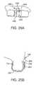
- FIGS. 25A and 25Billustrate perspective and side views, respectively, of an oral appliance which may have its transducer assembly or a coupling member attached to the gingival surface to conduct vibrations through the gingival tissue and underlying bone.
- FIG. 26illustrates an example of how multiple oral appliance DAP assemblies or transducers may be placed on multiple teeth throughout the user's mouth.
- FIGS. 27A and 27Billustrate perspective and side views, respectively, of an oral appliance (similar to a variation shown above) which may have a DAP unit positioned adjacent to or upon the gingival surface to physically separate the DAP from the transducer to attenuate or eliminate feedback.
- FIG. 28illustrates another variation of a removable oral appliance supported by an arch and having a DAP unit integrated within the arch.
- FIG. 29shows yet another variation illustrating at least one DAP and optionally additional DAP units positioned around the user's mouth and in wireless communication with the electronics and/or transducer assembly.
- FIGS. 1A-1Dshow an exemplary intra-oral entertainment system that includes a mouth wearable DAP 1 .
- the DAPhas a data storage device such as a solid-state memory 6 .
- An embedded software applicationallows users to transfer MP3 files to the player.
- the DAPalso includes utilities for copying music from the radio, CDs, radio or Web sites and the ability to organize and create custom lists of songs in the order the user wants to hear them (playlist).
- the DAP 1can contain a radio receiver 7 such as an AM/FM receiver.
- One exemplary radio receiveris the Si473x AM/FM radio receiver which is fully integrated from antenna input to audio output-requiring only two external components.
- the DAP 1includes a linking unit 8 such as a wireless transceiver (Bluetooth, wireless USB) or a wired transceiver (USB cable) that enables a computer 2 to place music content into the memory 6 or to modify the content of the memory 6 accordingly.
- the computer 2can have a Bluetooth transceiver at a charging station 3 that communicates with the Bluetooth transceiver linking unit 8 in the DAP 1 .
- the DAP 1can receive the data transmitted over the Bluetooth protocol and drive a bone conduction transducer 9 to render or transmit sound to the user.
- the DAP 1can receive FM transmission from an FM station 4 through a radio receiver 7 ( FIG. 1C ) and drive the bone conductor transceiver 9 to transmit sound to the user.
- the memorycan be solid-state memory or can be a mechanical memory such as a Microdrive, available from IBM.
- the advantage to solid-state memoryis that there are no moving parts, which means better reliability and no skips in the music.
- the Microdrive type memoryprovides larger capacity to store more songs.
- Other components of the playercan include the following: USB data port, microprocessor, digital signal processor (DSP), display, playback controls, audio port, amplifier, and power supply, for example.
- the microprocessorcontrols the operation of the player. It monitors user input through the playback controls, displays information about the current song on the LCD panel and sends directions to the DSP chip that tells the DSP exactly how to process the audio. To do this, the player retrieves the song from memory 6 , decompresses the MP3 encoding using the DSP if needed. The player then runs the decompressed bytes through a digital-to-analog converter into sound waves and amplifies the analog signal, and drives the transducer to contact the tooth or teeth and allow the song to be heard through bone conduction.
- the playersalso have built-in AM or FM radio tuner, providing users with an additional source of entertainment. Radio listeners can record the tunes from their favorite stations in the MP3 format, among others, and add the song to their playlist.
- the playersinclude an FM transmitter to playback the stored music on an external FM radio using unused frequencies.
- the music contentcan be purchased from stores such as Apple's iTunes, or alternatively the user can use a ripper to copy songs from CDs to the memory.
- An MP3 encodercan compress the song into the MP3 format to be played from an MP3 player.
- the DAP 1can be used for swimming or in wet environment activities.
- the DAP 1can be wirelessly connected to other devices via RF or electromagnetic, Bluetooth for either real time data transfer or sending data to the memory.
- the deviceprovides an electronic and transducer device that can be attached, adhered, or otherwise embedded into or upon a removable oral appliance or other oral device to form a medical tag containing user identifiable information.
- a removable oral appliance or other oral devicemay be a custom-made device fabricated from a thermal forming process utilizing a replicate model of a dental structure obtained by conventional dental impression and/or imaging methods.
- the electronic and transducer assemblymay receive incoming sounds either directly or through a receiver to process and amplify the signals and transmit the processed sounds via a vibrating transducer element coupled to a tooth or other bone structure, such as the maxillary, mandibular, or palatine bone structure.
- the computer 2can communicate with the linking unit 8 through a USB connection, among others.
- the USB connectioncan be activated when the device 1 is plugged into a recharging station 3 for recharging the battery in the DAP 1 .
- the DAP 1can be mounted on a battery charging system for use with an induction charger to charge the intraoral appliance 1 .
- the battery charging systemcan charge a number of devices. Accordingly, a plurality of such devices can be simultaneously, and efficiently, charged using a single induction charger.
- the coil portion 3 ′′picks up electromagnetic energy emanating from the charger base station 3 ′.
- the energyis in the form of electrical current which is provided to a charger regulator 3 ′′′.
- the charger regulatorboosts the voltage and smoothes out variations in the received energy using one or more filters.
- One or more filterscan be used to remove electrical noise.
- the regulated DC outputis provided to a charger which converts the energy into a suitable form for charging a energy storage device such as a super-capacitor or a battery, among others.
- the chargercan be optimized for different battery technology. For example, NiCad batteries require a certain set charging characteristics, and Lithium Ion batteries require another set charging characteristics.
- the chargercustomizes the energy provided by the charger regulator for the specific chemistry or requirements of the battery to optimize the battery charging operation.
- the connection between the charger and the batterycan be separated after charging to minimize size and/or weight of the portable appliance.
- the energy from the batteryis provided to a second regulator that provides the voltage needed by the electronics in the DAP appliance.
- the DAPhas a housing having a shape which is conformable to at least a portion of at least one tooth; an actuatable transducer disposed within or upon the housing and in vibratory communication with a surface of the at least one tooth; and a wireless communication transceiver coupled to the transducer to provide received sound to the user and to provide communication for the user.
- the DAP devicecan be an oral appliance having a shape which conforms to the at least one tooth.
- An electronic assemblycan be disposed within or upon the housing and which is in communication with the transducer.
- the device 1provides an electronic and transducer device 9 that can be attached, adhered, or otherwise embedded into or upon a removable oral appliance or other oral device to form a medical tag containing user identifiable information.
- a removable oral appliance or other oral devicemay be a custom-made device fabricated from a thermal forming process utilizing a replicate model of a dental structure obtained by conventional dental impression methods.
- the electronic and transducer assemblymay receive incoming sounds either directly or through a receiver to process and amplify the signals and transmit the processed sounds via a vibrating transducer element coupled to a tooth or other bone structure, such as the maxillary, mandibular, or palatine bone structure.
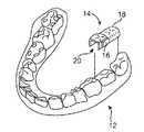
- a user's mouth and dentition 10is illustrated showing one possible location for removably attaching the DAP assembly 14 upon or against at least one tooth, such as a molar 12 .
- the user's tongue TG and palate PLare also illustrated for reference.
- An electronics and/or transducer assembly 16may be attached, adhered, or otherwise embedded into or upon the assembly 14 , as described below in further detail.
- FIG. 2Ashows a perspective view of the user's lower dentition illustrating the DAP assembly 14 comprising a removable oral appliance 18 and the electronics and/or transducer assembly 16 positioned along a side surface of the assembly 14 .
- oral appliance 18may be fitted upon two molars 12 within tooth engaging channel 20 defined by oral appliance 18 for stability upon the user's teeth, although in other variations, a single molar or tooth may be utilized. Alternatively, more than two molars may be utilized for the oral appliance 18 to be attached upon or over.
- electronics and/or transducer assembly 16is shown positioned upon a side surface of oral appliance 18 such that the assembly 16 is aligned along a buccal surface of the tooth 12 ; however, other surfaces such as the lingual surface of the tooth 12 and other positions may also be utilized.
- the figuresare illustrative of variations and are not intended to be limiting; accordingly, other configurations and shapes for oral appliance 18 are intended to be included herein.
- FIG. 4illustrates a schematic representation of one variation of DAP assembly 14 utilizing an extra-buccal transmitter assembly 22 , which may generally comprise data storage 30 for storing sound/musical content and which is electrically connected to processor 32 for processing the audio signals.
- Processor 32may be connected electrically to transmitter 34 for transmitting the processed signals to the electronics and/or transducer assembly 16 disposed upon or adjacent to the user's teeth.
- the data storage 30 and processor 32may be configured to handle audio signals in any practicable range, but may be configured in one variation to process auditory signals ranging from, e.g., 250 Hertz to 20,000 Hertz.
- the signals transmitted 24 by transmitter 34may be received by electronics and/or transducer assembly 16 via receiver 38 , which may be connected to an internal processor for additional processing of the received signals.
- the received signalsmay be communicated to transducer 40 , which may vibrate correspondingly against a surface of the tooth to conduct the vibratory signals through the tooth and bone and subsequently to the middle ear to facilitate hearing of the user.
- Transducer 40may be configured as any number of different vibratory mechanisms.
- transducer 40may be an electromagnetically actuated transducer.
- transducer 40may be in the form of a piezoelectric crystal having a range of vibratory frequencies, e.g., between 250 to 4000 Hz.
- the electronicsmay be contained as a separate assembly 90 which is encapsulated within housing 62 and the transducer 92 may be maintained separately from assembly 90 but also within housing 62 .
- transducer 92may be urged against the tooth surface via a spring or other biasing element 94 and actuated via any of the mechanisms described above.
- the electronics 150 and the transducer 152may be separated from one another such that electronics 150 remain disposed within housing 62 but transducer 152 , connected via wire 154 , is located beneath dental oral appliance 60 along an occlusal surface of the tooth, as shown in FIG. 15 .
- vibrationsare transmitted via the transducer 152 through the occlusal surface of the tooth.
- the usermay bite down upon the oral appliance 60 and transducer 152 to mechanically compress the transducer 152 against the occlusal surface to further enhance the mechanical contact between the transducer 152 and underlying tooth to further facilitate transmission therethrough.
- FIGS. 18A and 18Dshow partial cross-sectional side and top views, respectively, of another variation in which oral appliance 180 may define a number of channels or grooves 184 along a top portion of oral appliance 180 .
- one or more transducers 182 , 186 , 188 , 190may be disposed such that they are in contact with the occlusal surface of the tooth and each of these transducers may be tuned to transmit frequencies uniformly.
- each of these transducersmay be tuned to transmit only at specified frequency ranges.
- each transducercan be programmed or preset for a different frequency response such that each transducer may be optimized for a different frequency response and/or transmission to deliver a relatively high-fidelity sound to the user.
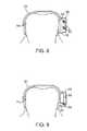
- FIGS. 19A and 19Billustrate an oral appliance 200 which may be pre-formed from a shape memory polymer or alloy or a superelastic material such as a Nickel-Titanium alloy, e.g., Nitinol.
- FIG. 19Ashows oral appliance 200 in a first configuration where members 202 , 204 are in an unbiased memory configuration.
- members 202 , 204When placed upon or against the tooth TH, members 202 , 204 may be deflected into a second configuration where members 202 ′, 204 ′ are deformed to engage tooth TH in a secure interference fit, as shown in FIG. 19B .
- the biased member 204 ′may be utilized to press the electronics and/or transducer assembly contained therein against the tooth surface as well as to maintain securement of the oral appliance 200 upon the tooth TH.
- removable oral appliance 210may have biased members to secure engage the tooth TH, as above.
- the ends of the members 212 , 214may be configured into curved portions under which a transducer element 218 coupled to electronics assembly 216 may be wedged or otherwise secured to ensure mechanical contact against the tooth surface.
- FIG. 21shows yet another variation in which the oral appliance is omitted entirely.
- a composite dental anchor or bracket 226as described above, may be adhered directly onto die tooth surface.
- bracket 226may be comprised of a biocompatible material, e.g., stainless steel, Nickel-Titanium, Nickel, ceramics, composites, etc., formed into a bracket and anchored onto the tooth surface.
- the bracket 226may be configured to have a shape 228 over which an electronics and/or transducer assembly 220 may be slid over or upon via a channel 222 having a corresponding receiving configuration 224 for engagement with bracket 226 .
- assembly 220may be directly engaged against bracket 226 , through which a transducer may directly vibrate into the underlying tooth TH. Additionally, in the event that assembly 220 is removed from the tooth TH, assembly 220 may be simply slid or rotated off bracket 226 and a replacement assembly may be put in its place upon bracket 226 .
- FIGS. 22A and 22Bshow partial cross-sectional side and perspective views, respectively, of yet another variation of an oral appliance 230 .
- the oral appliance 230may be configured to omit an occlusal surface portion of the oral appliance 230 and instead engages the side surfaces of the tooth TH, such as the lingual and buccal surfaces only.
- the electronics and/or transducer assembly 234may be contained, as above, within a housing 232 for contact against the tooth surface.
- one or more optional cross-members 236may connect the side portions of the oral appliance 230 to provide some structural stability when placed upon the tooth.
- This variationmay define an occlusal surface opening 238 such that when placed upon the tooth, the user may freely bite down directly upon the natural occlusal surface of the tooth unobstructed by the oral appliance device, thereby providing for enhanced comfort to the user.
- vibrationsmay be transmitted directly into the underlying bone or tissue structures rather than transmitting directly through the tooth or teeth of the user.
- an oral appliance 240is illustrated positioned upon the user's tooth, in this example upon a molar located along the upper row of teeth.
- the electronics and/or transducer assembly 242is shown as being located along the buccal surface of the tooth.
- a conduction transmission member 244such as a rigid or solid metallic member, may be coupled to the transducer in assembly 242 and extend from oral appliance 240 to a post or screw 246 which is implanted directly into the underlying bone 248 , such as the maxillary bone, as shown in the partial cross-sectional view of FIG. 23B .
- the vibrations generated by the transducermay be transmitted through transmission member 244 and directly into post or screw 246 , which in turn transmits the vibrations directly into and through the bone 248 for transmission to the user's inner ear.
- FIG. 24illustrates a partial cross-sectional view of an oral appliance 250 placed upon the user's tooth TH with the electronics and/or transducer assembly 252 located along the lingual surface of the tooth.
- the vibrationsmay be transmitted through the conduction transmission member 244 and directly into post or screw 246 , which in this example is implanted into the palatine bone PL.
- post or screw 246which in this example is implanted into the palatine bone PL.
- Other variationsmay utilize this arrangement located along the lower row of teeth for transmission to a post or screw 246 drilled into the mandibular bone.
- a transducermay be attached, coupled, or otherwise adhered directly to the gingival tissue surface adjacent to the teeth.
- an oral appliance 260may have an electronics assembly 262 positioned along its side with an electrical wire 264 extending therefrom to a transducer assembly 266 attached to the gingival tissue surface 268 next to the tooth TH.
- Transducer assembly 266may be attached to the tissue surface 268 via an adhesive, structural support arm extending from oral appliance 260 , a dental screw or post, or any other structural mechanism. In use, the transducer may vibrate and transmit directly into the underlying gingival tissue, which may conduct the signals to the underlying bone.
- each transducer 270 , 272 , 274 , 276can be programmed or preset for a different frequency response such that each transducer may be optimized for a different frequency response and/or transmission to deliver a relatively high-fidelity sound to the user.
- each of the different transducers 270 , 272 , 274 , 276can also be programmed to vibrate in a manner which indicates the directionality of sound played by the DAP worn by the user.
- different transducers positioned at different locations within the user's mouthcan vibrate in a specified manner by providing sound or vibrational queues to inform the user which direction a sound arises relative to an orientation of the user.
- a first transducer located, e.g., on a user's left toothcan be programmed to vibrate for sound originating from the user's left side.
- a second transducer located, e.g., on a user's right toothcan be programmed to vibrate for sound originating from the user's right side.
- multi-directional soundsuch as THX sound can be played for the user's enjoyment.
- Other variations and queuesmay be utilized as these examples are intended to be illustrative of potential variations.
- the DAPmay be integrated directly into the electronics and/or transducer assembly, as described above.
- the DAP unitmay be positioned at a distance from the transducer assemblies.
- DAP unit 282may be separated from electronics and/or transducer assembly 280 , as shown in FIGS. 27A and 27B .
- the DAP unit 282 positioned upon or adjacent to the gingival surface 268may be electrically connected via wire(s) 264 .
- FIG. 28illustrates another variation 290 which utilizes an arch 19 connecting one or more tooth retaining portions 21 , 23 , as described above.
- the DAP unit 294may be integrated within or upon the arch 19 separated from the transducer assembly 292 .
- One or more wires 296 routed through arch 19may electrically connect the DAP unit 294 to the assembly 292 .
- DAP unit 294 and assembly 292may be wirelessly coupled to one another, as described above.
- FIG. 29illustrates another variation where at least one DAP 302 (or optionally any number of additional DAPs 304 , 306 ) may be positioned within the mouth of the user while physically separated from the electronics and/or transducer assembly 300 . In this manner, the one or optionally more DAPs 302 , 304 , 306 may be wirelessly coupled to the electronics and/or transducer assembly 300 .
Landscapes
- Physics & Mathematics (AREA)
- Engineering & Computer Science (AREA)
- Acoustics & Sound (AREA)
- Signal Processing (AREA)
- Dental Tools And Instruments Or Auxiliary Dental Instruments (AREA)
- Details Of Audible-Bandwidth Transducers (AREA)
- Reverberation, Karaoke And Other Acoustics (AREA)
- Circuit For Audible Band Transducer (AREA)
Abstract
Description
- WMA—Windows Media Audio
- WAV—Waveform Audio
- MIDI—Music Instrument Digital Interface.
- AAC—Advanced Audio Coding
- Ogg Vorbis—A free, open and un-patented music format
- ADPCM—Adaptive Differential Pulse Code Modulation
- ASF—Advanced Streaming Format
- VQF—Vector Quantization Format
- ATRAC—Sony's Adaptive
Transform Acoustic Coding 3
Claims (24)
Priority Applications (13)
| Application Number | Priority Date | Filing Date | Title |
|---|---|---|---|
| US12/464,310US8224013B2 (en) | 2007-08-27 | 2009-05-12 | Headset systems and methods |
| CA2761715ACA2761715C (en) | 2009-05-12 | 2010-05-11 | Headset systems and methods |
| BRPI1007753ABRPI1007753A2 (en) | 2009-05-12 | 2010-05-11 | intraoral digital audio player and method for reproducing audio content |
| EP10775364AEP2430842A4 (en) | 2009-05-12 | 2010-05-11 | Headset systems and methods |
| PCT/US2010/034312WO2010132399A1 (en) | 2009-05-12 | 2010-05-11 | Headset systems and methods |
| AU2010247811AAU2010247811B2 (en) | 2009-05-12 | 2010-05-11 | Headset systems and methods |
| JP2012510915AJP5122023B2 (en) | 2009-05-12 | 2010-05-11 | Headset system and method |
| GB1007886AGB2470279A (en) | 2009-05-12 | 2010-05-11 | Mouth wearable digital audio player |
| CN201310473012.1ACN103607674A (en) | 2009-05-12 | 2010-05-11 | Headset system and method |
| CN2010800312643ACN102461211A (en) | 2009-05-12 | 2010-05-11 | Headset system and method |
| US13/493,722US8660278B2 (en) | 2007-08-27 | 2012-06-11 | Headset systems and methods |
| JP2012233698AJP2013057952A (en) | 2009-05-12 | 2012-10-23 | Headset system and method |
| US14/186,179US20140270268A1 (en) | 2007-08-27 | 2014-02-21 | Headset systems and methods |
Applications Claiming Priority (2)
| Application Number | Priority Date | Filing Date | Title |
|---|---|---|---|
| US11/845,712US20080064993A1 (en) | 2006-09-08 | 2007-08-27 | Methods and apparatus for treating tinnitus |
| US12/464,310US8224013B2 (en) | 2007-08-27 | 2009-05-12 | Headset systems and methods |
Related Parent Applications (1)
| Application Number | Title | Priority Date | Filing Date |
|---|---|---|---|
| US11/845,712Continuation-In-PartUS20080064993A1 (en) | 2006-09-08 | 2007-08-27 | Methods and apparatus for treating tinnitus |
Related Child Applications (1)
| Application Number | Title | Priority Date | Filing Date |
|---|---|---|---|
| US13/493,722ContinuationUS8660278B2 (en) | 2007-08-27 | 2012-06-11 | Headset systems and methods |
Publications (2)
| Publication Number | Publication Date |
|---|---|
| US20100290647A1 US20100290647A1 (en) | 2010-11-18 |
| US8224013B2true US8224013B2 (en) | 2012-07-17 |
Family
ID=42315165
Family Applications (3)
| Application Number | Title | Priority Date | Filing Date |
|---|---|---|---|
| US12/464,310Active2028-11-17US8224013B2 (en) | 2007-08-27 | 2009-05-12 | Headset systems and methods |
| US13/493,722ActiveUS8660278B2 (en) | 2007-08-27 | 2012-06-11 | Headset systems and methods |
| US14/186,179AbandonedUS20140270268A1 (en) | 2007-08-27 | 2014-02-21 | Headset systems and methods |
Family Applications After (2)
| Application Number | Title | Priority Date | Filing Date |
|---|---|---|---|
| US13/493,722ActiveUS8660278B2 (en) | 2007-08-27 | 2012-06-11 | Headset systems and methods |
| US14/186,179AbandonedUS20140270268A1 (en) | 2007-08-27 | 2014-02-21 | Headset systems and methods |
Country Status (9)
| Country | Link |
|---|---|
| US (3) | US8224013B2 (en) |
| EP (1) | EP2430842A4 (en) |
| JP (2) | JP5122023B2 (en) |
| CN (2) | CN102461211A (en) |
| AU (1) | AU2010247811B2 (en) |
| BR (1) | BRPI1007753A2 (en) |
| CA (1) | CA2761715C (en) |
| GB (1) | GB2470279A (en) |
| WO (1) | WO2010132399A1 (en) |
Cited By (3)
| Publication number | Priority date | Publication date | Assignee | Title |
|---|---|---|---|---|
| US10348350B2 (en) | 2016-09-22 | 2019-07-09 | Sonitus Technologies, Inc. | Two-way communication system and method of use |
| US10412512B2 (en) | 2006-05-30 | 2019-09-10 | Soundmed, Llc | Methods and apparatus for processing audio signals |
| US10484805B2 (en) | 2009-10-02 | 2019-11-19 | Soundmed, Llc | Intraoral appliance for sound transmission via bone conduction |
Families Citing this family (20)
| Publication number | Priority date | Publication date | Assignee | Title |
|---|---|---|---|---|
| US8224013B2 (en) | 2007-08-27 | 2012-07-17 | Sonitus Medical, Inc. | Headset systems and methods |
| US11399234B2 (en) | 2011-12-23 | 2022-07-26 | Shenzhen Shokz Co., Ltd. | Bone conduction speaker and compound vibration device thereof |
| US11611834B2 (en) | 2011-12-23 | 2023-03-21 | Shenzhen Shokz Co., Ltd. | Bone conduction speaker and compound vibration device thereof |
| WO2013099228A2 (en) | 2011-12-30 | 2013-07-04 | Makita Corporation | Charger, battery pack charging system and cordless power tool system |
| US9044291B2 (en) | 2012-05-09 | 2015-06-02 | Plantronics, Inc. | Jaw powered electric generator |
| US9781496B2 (en) | 2012-10-25 | 2017-10-03 | Milwaukee Electric Tool Corporation | Worksite audio device with wireless interface |
| US9017069B2 (en)* | 2013-05-13 | 2015-04-28 | Elwha Llc | Oral illumination systems and methods |
| US12413915B2 (en) | 2014-01-06 | 2025-09-09 | Shenzhen Shokz Co., Ltd. | Systems and methods for suppressing sound leakage |
| US11363392B2 (en) | 2014-01-06 | 2022-06-14 | Shenzhen Shokz Co., Ltd. | Systems and methods for suppressing sound leakage |
| US10528081B2 (en) | 2014-12-26 | 2020-01-07 | Intel Corporation | Head mounted wearable device power supply system |
| ES2884329T3 (en)* | 2015-08-13 | 2021-12-10 | Shenzhen Voxtech Co Ltd | Bone conduction speaker |
| US10602284B2 (en)* | 2016-07-18 | 2020-03-24 | Cochlear Limited | Transducer management |
| GB2557258B8 (en)* | 2016-12-02 | 2019-09-25 | Gdm Int Ltd | A system and method for an in- mouth communicator |
| US11760026B2 (en)* | 2017-10-10 | 2023-09-19 | Biomechanics Consulting and Research, LLC | Instrumented intra-oral appliance computationally designed for optimized fitting and functionality |
| KR101924549B1 (en) | 2017-10-31 | 2018-12-04 | 박미라 | Head gear for fixing mouthpiece |
| US11699920B2 (en)* | 2020-02-04 | 2023-07-11 | Samsung Electronics Co., Ltd. | Device and method for receiving power wirelessly |
| WO2021243558A1 (en) | 2020-06-02 | 2021-12-09 | 雷铭科技有限公司 | Integrated bone-conduction sound production device and method |
| CN113749303A (en)* | 2020-06-02 | 2021-12-07 | 北京晓聪科技有限公司 | Electronic cigarette equipment and sound production method |
| CN112286289A (en)* | 2020-10-30 | 2021-01-29 | 刘啸 | Buccal wearable device, processing method and storage medium |
| WO2024159362A1 (en)* | 2023-01-30 | 2024-08-08 | 深圳市韶音科技有限公司 | Movement module and electronic device |
Citations (167)
| Publication number | Priority date | Publication date | Assignee | Title |
|---|---|---|---|---|
| US2045404A (en) | 1933-05-24 | 1936-06-23 | Sonotone Corp | Piezoelectric vibrator device |
| US2161169A (en)* | 1938-01-24 | 1939-06-06 | Erwin H Wilson | Dentiphone |
| US2318872A (en) | 1941-07-17 | 1943-05-11 | Goodman Mfg Co | Extensible conveyer |
| US2977425A (en) | 1959-09-14 | 1961-03-28 | Irwin H Cole | Hearing aid |
| US2995633A (en)* | 1958-09-25 | 1961-08-08 | Henry K Puharich | Means for aiding hearing |
| US3156787A (en)* | 1962-10-23 | 1964-11-10 | Henry K Puharich | Solid state hearing system |
| US3170993A (en)* | 1962-01-08 | 1965-02-23 | Henry K Puharich | Means for aiding hearing by electrical stimulation of the facial nerve system |
| US3267931A (en) | 1963-01-09 | 1966-08-23 | Henry K Puharich | Electrically stimulated hearing with signal feedback |
| US3325743A (en) | 1965-12-23 | 1967-06-13 | Zenith Radio Corp | Bimorph flexural acoustic amplifier |
| US3787641A (en) | 1972-06-05 | 1974-01-22 | Setcom Corp | Bone conduction microphone assembly |
| US3894196A (en) | 1974-05-28 | 1975-07-08 | Zenith Radio Corp | Binaural hearing aid system |
| US3985977A (en) | 1975-04-21 | 1976-10-12 | Motorola, Inc. | Receiver system for receiving audio electrical signals |
| US4025732A (en) | 1975-08-04 | 1977-05-24 | Hartmut Traunmuller | Method and device for presenting information to deaf persons |
| US4150262A (en) | 1974-11-18 | 1979-04-17 | Hiroshi Ono | Piezoelectric bone conductive in ear voice sounds transmitting and receiving apparatus |
| US4382780A (en)* | 1982-05-17 | 1983-05-10 | Kurz Craven H | Radio wave vibrational orthodontic appliance |
| US4498461A (en) | 1981-12-01 | 1985-02-12 | Bo Hakansson | Coupling to a bone-anchored hearing aid |
| US4591668A (en) | 1984-05-08 | 1986-05-27 | Iwata Electric Co., Ltd. | Vibration-detecting type microphone |
| US4612915A (en) | 1985-05-23 | 1986-09-23 | Xomed, Inc. | Direct bone conduction hearing aid device |
| US4642769A (en) | 1983-06-10 | 1987-02-10 | Wright State University | Method and apparatus for providing stimulated exercise of paralyzed limbs |
| US4738268A (en) | 1985-07-24 | 1988-04-19 | Tokos Medical Corporation | Relative time clock |
| US4817044A (en) | 1987-06-01 | 1989-03-28 | Ogren David A | Collection and reporting system for medical appliances |
| US4832033A (en) | 1985-04-29 | 1989-05-23 | Bio-Medical Research Limited | Electrical stimulation of muscle |
| US4920984A (en) | 1986-10-15 | 1990-05-01 | Sunstar Kabushiki Kaisha | Mouthpiece and method for producing the same |
| US4982434A (en) | 1989-05-30 | 1991-01-01 | Center For Innovative Technology | Supersonic bone conduction hearing aid and method |
| US5012520A (en) | 1988-05-06 | 1991-04-30 | Siemens Aktiengesellschaft | Hearing aid with wireless remote control |
| US5033999A (en)* | 1989-10-25 | 1991-07-23 | Mersky Barry L | Method and apparatus for endodontically augmenting hearing |
| US5047994A (en) | 1989-05-30 | 1991-09-10 | Center For Innovative Technology | Supersonic bone conduction hearing aid and method |
| US5060526A (en) | 1989-05-30 | 1991-10-29 | Schlumberger Industries, Inc. | Laminated semiconductor sensor with vibrating element |
| US5082007A (en) | 1990-01-24 | 1992-01-21 | Loren S. Adell | Multi-laminar mouthguards |
| US5165131A (en)* | 1989-12-29 | 1992-11-24 | Staar Development Co., S.A. | Teeth cleaning apparatus |
| US5233987A (en) | 1992-07-09 | 1993-08-10 | Empi, Inc. | System and method for monitoring patient's compliance |
| US5323468A (en) | 1992-06-30 | 1994-06-21 | Bottesch H Werner | Bone-conductive stereo headphones |
| US5325436A (en) | 1993-06-30 | 1994-06-28 | House Ear Institute | Method of signal processing for maintaining directional hearing with hearing aids |
| US5326349A (en)* | 1992-07-09 | 1994-07-05 | Baraff David R | Artificial larynx |
| US5372142A (en) | 1993-02-17 | 1994-12-13 | Poul Madsen Medical Devices Ltd. | Cochlear response audiometer |
| US5402496A (en) | 1992-07-13 | 1995-03-28 | Minnesota Mining And Manufacturing Company | Auditory prosthesis, noise suppression apparatus and feedback suppression apparatus having focused adaptive filtering |
| US5403262A (en) | 1993-03-09 | 1995-04-04 | Microtek Medical, Inc. | Minimum energy tinnitus masker |
| US5447489A (en)* | 1989-08-17 | 1995-09-05 | Issalene; Robert | Bone conduction hearing aid device |
| US5455842A (en)* | 1994-01-12 | 1995-10-03 | Mersky; Barry | Method and apparatus for underwater communication |
| US5460593A (en)* | 1993-08-25 | 1995-10-24 | Audiodontics, Inc. | Method and apparatus for imparting low amplitude vibrations to bone and similar hard tissue |
| US5523745A (en)* | 1988-12-16 | 1996-06-04 | Zofcom Systems, Inc. | Tongue activated communications controller |
| EP0715838A2 (en) | 1994-12-02 | 1996-06-12 | P & B RESEARCH AB | A device in hearing aids |
| US5546459A (en) | 1993-11-01 | 1996-08-13 | Qualcomm Incorporated | Variable block size adaptation algorithm for noise-robust acoustic echo cancellation |
| US5558618A (en) | 1995-01-23 | 1996-09-24 | Maniglia; Anthony J. | Semi-implantable middle ear hearing device |
| US5565759A (en) | 1994-12-15 | 1996-10-15 | Intel Corporation | Smart battery providing battery life and recharge time prediction |
| US5579284A (en)* | 1995-07-21 | 1996-11-26 | May; David F. | Scuba diving voice and communication system using bone conducted sound |
| US5616027A (en) | 1995-04-18 | 1997-04-01 | Jacobs; Allison J. | Custom dental tray |
| US5624376A (en) | 1993-07-01 | 1997-04-29 | Symphonix Devices, Inc. | Implantable and external hearing systems having a floating mass transducer |
| US5661813A (en) | 1994-10-26 | 1997-08-26 | Nippon Telegraph And Telephone Corporation | Method and apparatus for multi-channel acoustic echo cancellation |
| US5706251A (en)* | 1995-07-21 | 1998-01-06 | Trigger Scuba, Inc. | Scuba diving voice and communication system using bone conducted sound |
| EP0824889A1 (en) | 1996-08-20 | 1998-02-25 | Buratto Advanced Technology S.r.l. | Transmission system using the human body as wave guide |
| US5760692A (en)* | 1996-10-18 | 1998-06-02 | Block; Douglas A. | Intra-oral tracking device |
| US5788656A (en) | 1997-02-28 | 1998-08-04 | Mino; Alfonso Di | Electronic stimulation system for treating tinnitus disorders |
| US5795287A (en) | 1996-01-03 | 1998-08-18 | Symphonix Devices, Inc. | Tinnitus masker for direct drive hearing devices |
| US5800336A (en) | 1993-07-01 | 1998-09-01 | Symphonix Devices, Inc. | Advanced designs of floating mass transducers |
| US5812496A (en) | 1997-10-20 | 1998-09-22 | Peck/Pelissier Partnership | Water resistant microphone |
| US5828765A (en) | 1996-05-03 | 1998-10-27 | Gable; Tony L. | Audio loudspeaker assembly for recessed lighting fixture and audio system using same |
| US5902167A (en)* | 1997-09-09 | 1999-05-11 | Sonic Bites, Llc | Sound-transmitting amusement device and method |
| US5914701A (en) | 1995-05-08 | 1999-06-22 | Massachusetts Institute Of Technology | Non-contact system for sensing and signalling by externally induced intra-body currents |
| US5961443A (en) | 1996-07-31 | 1999-10-05 | East Carolina University | Therapeutic device to ameliorate stuttering |
| US5984681A (en) | 1997-09-02 | 1999-11-16 | Huang; Barney K. | Dental implant and method of implanting |
| US6029558A (en) | 1997-05-12 | 2000-02-29 | Southwest Research Institute | Reactive personnel protection system |
| US6047074A (en) | 1996-07-09 | 2000-04-04 | Zoels; Fred | Programmable hearing aid operable in a mode for tinnitus therapy |
| US6068590A (en) | 1997-10-24 | 2000-05-30 | Hearing Innovations, Inc. | Device for diagnosing and treating hearing disorders |
| US6072885A (en) | 1994-07-08 | 2000-06-06 | Sonic Innovations, Inc. | Hearing aid device incorporating signal processing techniques |
| US6072884A (en) | 1997-11-18 | 2000-06-06 | Audiologic Hearing Systems Lp | Feedback cancellation apparatus and methods |
| US6075557A (en) | 1997-04-17 | 2000-06-13 | Sharp Kabushiki Kaisha | Image tracking system and method and observer tracking autostereoscopic display |
| US6115477A (en)* | 1995-01-23 | 2000-09-05 | Sonic Bites, Llc | Denta-mandibular sound-transmitting system |
| US6118882A (en) | 1995-01-25 | 2000-09-12 | Haynes; Philip Ashley | Communication method |
| US6171229B1 (en) | 1996-08-07 | 2001-01-09 | St. Croix Medical, Inc. | Ossicular transducer attachment for an implantable hearing device |
| US6184651B1 (en)* | 2000-03-20 | 2001-02-06 | Motorola, Inc. | Contactless battery charger with wireless control link |
| US6223018B1 (en) | 1996-12-12 | 2001-04-24 | Nippon Telegraph And Telephone Corporation | Intra-body information transfer device |
| US6239705B1 (en)* | 2000-04-19 | 2001-05-29 | Jeffrey Glen | Intra oral electronic tracking device |
| US20010003788A1 (en) | 1993-07-01 | 2001-06-14 | Ball Geoffrey R. | Implantable and external hearing system having a floating mass transducer |
| US20010051776A1 (en) | 1998-10-14 | 2001-12-13 | Lenhardt Martin L. | Tinnitus masker/suppressor |
| US6333269B2 (en) | 1997-09-16 | 2001-12-25 | Tokyo Electron Limited | Plasma treatment system and method |
| US20020026091A1 (en) | 2000-08-25 | 2002-02-28 | Hans Leysieffer | Implantable hearing system with means for measuring its coupling quality |
| US6377693B1 (en) | 1994-06-23 | 2002-04-23 | Hearing Innovations Incorporated | Tinnitus masking using ultrasonic signals |
| US6394969B1 (en) | 1998-10-14 | 2002-05-28 | Sound Techniques Systems Llc | Tinnitis masking and suppressor using pulsed ultrasound |
| US20020071581A1 (en) | 2000-03-28 | 2002-06-13 | Hans Leysieffer | Partially or fully implantable hearing system |
| US20020077831A1 (en) | 2000-11-28 | 2002-06-20 | Numa Takayuki | Data input/output method and system without being notified |
| US20020122563A1 (en) | 2001-03-02 | 2002-09-05 | Schumaier Daniel R. | Bone conduction hearing aid |
| US6504942B1 (en) | 1998-01-23 | 2003-01-07 | Sharp Kabushiki Kaisha | Method of and apparatus for detecting a face-like region and observer tracking display |
| US6538558B2 (en) | 1996-09-20 | 2003-03-25 | Alps Electric Co., Ltd. | Communication system |
| US20030059078A1 (en) | 2001-06-21 | 2003-03-27 | Downs Edward F. | Directional sensors for head-mounted contact microphones |
| EP1299052A1 (en) | 2000-07-12 | 2003-04-09 | Entific Medical Systems AB | Anchoring element |
| US20030091200A1 (en) | 2001-10-09 | 2003-05-15 | Pompei Frank Joseph | Ultrasonic transducer for parametric array |
| US6585637B2 (en) | 1998-10-15 | 2003-07-01 | St. Croix Medical, Inc. | Method and apparatus for fixation type feedback reduction in implantable hearing assistance systems |
| US6631197B1 (en) | 2000-07-24 | 2003-10-07 | Gn Resound North America Corporation | Wide audio bandwidth transduction method and device |
| US6633747B1 (en)* | 2000-07-12 | 2003-10-14 | Lucent Technologies Inc. | Orthodontic appliance audio receiver |
| US20030212319A1 (en) | 2000-10-10 | 2003-11-13 | Magill Alan Remy | Health monitoring garment |
| US6682472B1 (en) | 1999-03-17 | 2004-01-27 | Tinnitech Ltd. | Tinnitus rehabilitation device and method |
| US20040057591A1 (en) | 2002-06-26 | 2004-03-25 | Frank Beck | Directional hearing given binaural hearing aid coverage |
| US6754472B1 (en) | 2000-04-27 | 2004-06-22 | Microsoft Corporation | Method and apparatus for transmitting power and data using the human body |
| US20040141624A1 (en) | 1999-03-17 | 2004-07-22 | Neuromonics Limited | Tinnitus rehabilitation device and method |
| US6778674B1 (en) | 1999-12-28 | 2004-08-17 | Texas Instruments Incorporated | Hearing assist device with directional detection and sound modification |
| US20040202344A1 (en)* | 2003-04-08 | 2004-10-14 | Muniswamappa Anjanappa | Method and apparatus for tooth bone conduction microphone |
| US20040202339A1 (en) | 2003-04-09 | 2004-10-14 | O'brien, William D. | Intrabody communication with ultrasound |
| US6826284B1 (en) | 2000-02-04 | 2004-11-30 | Agere Systems Inc. | Method and apparatus for passive acoustic source localization for video camera steering applications |
| US20040243481A1 (en) | 2000-04-05 | 2004-12-02 | Therics, Inc. | System and method for rapidly customizing design, manufacture and/or selection of biomedical devices |
| US20040247143A1 (en) | 2001-10-01 | 2004-12-09 | Amphicom | Device for listening to voice and/or musical signals by means of cranial bone transmission |
| US20050020873A1 (en) | 2003-07-23 | 2005-01-27 | Epic Biosonics Inc. | Totally implantable hearing prosthesis |
| US20050037312A1 (en) | 2003-06-20 | 2005-02-17 | Aso International, Inc | Orthodontic retainer |
| US20050070782A1 (en) | 2003-07-17 | 2005-03-31 | Dmitri Brodkin | Digital technologies for planning and carrying out dental restorative procedures |
| US20050067816A1 (en) | 2002-12-18 | 2005-03-31 | Buckman Robert F. | Method and apparatus for body impact protection |
| US6885753B2 (en) | 2000-01-27 | 2005-04-26 | New Transducers Limited | Communication device using bone conduction |
| US20050129257A1 (en) | 2003-12-12 | 2005-06-16 | Nec Tokin Corporation | Acoustic vibration generating element |
| US6917688B2 (en) | 2002-09-11 | 2005-07-12 | Nanyang Technological University | Adaptive noise cancelling microphone system |
| US20050196008A1 (en) | 2003-04-08 | 2005-09-08 | Muniswamappa Anjanappa | Method and apparatus for tooth bone conduction microphone |
| US6941952B1 (en) | 2004-12-02 | 2005-09-13 | Rush, Iii Gus A. | Athletic mouthpiece capable of sensing linear and rotational forces and protective headgear for use with the same |
| US6954668B1 (en)* | 2001-10-11 | 2005-10-11 | Cuozzo John W | Apparatus and method for intra-oral stimulation of the trigeminal nerve |
| US20050241646A1 (en) | 2004-03-10 | 2005-11-03 | Apneos Corp. | System and method for treatment of upper airway disorders |
| US6985599B2 (en) | 2000-06-02 | 2006-01-10 | P&B Research Ab | Vibrator for bone conducted hearing aids |
| US20060008106A1 (en) | 2004-07-06 | 2006-01-12 | Harper Patrick S | System and method for securing headphone transducers |
| US20060025648A1 (en) | 2002-12-11 | 2006-02-02 | No. 182 Corporate Ventures Ltd. | Surgically implantable hearing aid |
| US7003099B1 (en) | 2002-11-15 | 2006-02-21 | Fortmedia, Inc. | Small array microphone for acoustic echo cancellation and noise suppression |
| EP1633284A1 (en) | 2003-05-30 | 2006-03-15 | Entific Medical Systems AB | Implant device |
| US20060064037A1 (en) | 2004-09-22 | 2006-03-23 | Shalon Ventures Research, Llc | Systems and methods for monitoring and modifying behavior |
| US7035415B2 (en) | 2000-05-26 | 2006-04-25 | Koninklijke Philips Electronics N.V. | Method and device for acoustic echo cancellation combined with adaptive beamforming |
| US7076077B2 (en) | 2001-07-05 | 2006-07-11 | Temco Japan Co., Ltd. | Bone conduction headset |
| US20060167335A1 (en) | 2005-01-26 | 2006-07-27 | Samsung Electronics Co., Ltd. | Method and device for tinnitus therapy |
| US7099822B2 (en) | 2002-12-10 | 2006-08-29 | Liberato Technologies, Inc. | System and method for noise reduction having first and second adaptive filters responsive to a stored vector |
| DE102005012975B3 (en) | 2005-03-21 | 2006-08-31 | Siemens Audiologische Technik Gmbh | Hearing aid apparatus with music play back apparatus provided by wireless transmission between two hearing aids |
| EP1718255A1 (en) | 2003-10-22 | 2006-11-08 | Entific Medical Systems AB | Anti-stuttering device |
| US20060270467A1 (en) | 2005-05-25 | 2006-11-30 | Song Jianming J | Method and apparatus of increasing speech intelligibility in noisy environments |
| US20060275739A1 (en) | 2005-06-03 | 2006-12-07 | Ray Charles D | Dental vibrator and acoustical unit with method for the inhibition of operative pain |
| US7162420B2 (en) | 2002-12-10 | 2007-01-09 | Liberato Technologies, Llc | System and method for noise reduction having first and second adaptive filters |
| US7171008B2 (en) | 2002-02-05 | 2007-01-30 | Mh Acoustics, Llc | Reducing noise in audio systems |
| US7171003B1 (en) | 2000-10-19 | 2007-01-30 | Lear Corporation | Robust and reliable acoustic echo and noise cancellation system for cabin communication |
| US7174022B1 (en) | 2002-11-15 | 2007-02-06 | Fortemedia, Inc. | Small array microphone for beam-forming and noise suppression |
| US20070036370A1 (en) | 2004-10-12 | 2007-02-15 | Microsoft Corporation | Method and apparatus for multi-sensory speech enhancement on a mobile device |
| US20070041595A1 (en) | 2005-07-07 | 2007-02-22 | Carazo Alfredo V | Bone-conduction hearing-aid transducer having improved frequency response |
| US20070050061A1 (en)* | 2005-08-31 | 2007-03-01 | Andre Klein | Audio player remote control system |
| US7206423B1 (en) | 2000-05-10 | 2007-04-17 | Board Of Trustees Of University Of Illinois | Intrabody communication for a hearing aid |
| US20070093733A1 (en) | 2005-10-21 | 2007-04-26 | Choy Daniel S | Method and apparatus for treatment of predominant-tone tinnitus |
| EP1783919A1 (en) | 2004-08-27 | 2007-05-09 | Victorion Technology Co., Ltd. | The nasal bone conduction wireless communication transmission equipment |
| US20070142072A1 (en) | 2005-12-19 | 2007-06-21 | Teodoro Lassally | Two way radio |
| US7246058B2 (en) | 2001-05-30 | 2007-07-17 | Aliph, Inc. | Detecting voiced and unvoiced speech using both acoustic and nonacoustic sensors |
| US7258533B2 (en) | 2004-12-30 | 2007-08-21 | Adaptivenergy, Llc | Method and apparatus for scavenging energy during pump operation |
| US7271569B2 (en)* | 2004-09-21 | 2007-09-18 | Motorola Inc. | Contact less charger with alignment indicator |
| EP1841284A1 (en) | 2006-03-29 | 2007-10-03 | Phonak AG | Hearing instrument for storing encoded audio data, method of operating and manufacturing thereof |
| US20070239294A1 (en)* | 2006-03-29 | 2007-10-11 | Andrea Brueckner | Hearing instrument having audio feedback capability |
| US20070258609A1 (en) | 2006-05-04 | 2007-11-08 | Siemens Audiologische Technik Gmbh | Method and apparatus for determining a target amplification curve for a hearing device |
| US20070265533A1 (en) | 2006-05-12 | 2007-11-15 | Bao Tran | Cuffless blood pressure monitoring appliance |
| US20070276270A1 (en) | 2006-05-24 | 2007-11-29 | Bao Tran | Mesh network stroke monitoring appliance |
| US20070280495A1 (en)* | 2006-05-30 | 2007-12-06 | Sonitus Medical, Inc. | Methods and apparatus for processing audio signals |
| US7310427B2 (en) | 2002-08-01 | 2007-12-18 | Virginia Commonwealth University | Recreational bone conduction audio device, system |
| US20080019557A1 (en) | 2006-07-19 | 2008-01-24 | Bevirt Joeben | Headset with fit adjustments and magnetic accessories |
| US20080021327A1 (en)* | 2006-05-12 | 2008-01-24 | Tarek Hessin Ahmed El-Bialy | Ultrasound stimulation devices and techniques |
| US7329226B1 (en) | 2004-07-06 | 2008-02-12 | Cardiac Pacemakers, Inc. | System and method for assessing pulmonary performance through transthoracic impedance monitoring |
| US7331349B2 (en) | 2003-01-23 | 2008-02-19 | Surgical Devices, Ltd., Co. Morningstar Holding Ltd. | Method and device for the prevention of snoring and sleep apnea |
| US7333624B2 (en) | 2003-09-24 | 2008-02-19 | Siemens Audiologische Technik Gmbh | Hearing aid device and operating method for automatically switching voltage supply to a connected external device |
| US20080064993A1 (en)* | 2006-09-08 | 2008-03-13 | Sonitus Medical Inc. | Methods and apparatus for treating tinnitus |
| US20080070181A1 (en)* | 2006-08-22 | 2008-03-20 | Sonitus Medical, Inc. | Systems for manufacturing oral-based hearing aid appliances |
| US7361216B2 (en) | 2004-05-17 | 2008-04-22 | 3M Innovative Properties Company | Dental compositions containing nanofillers and related methods |
| US20080304677A1 (en) | 2007-06-08 | 2008-12-11 | Sonitus Medical Inc. | System and method for noise cancellation with motion tracking capability |
| US20090028352A1 (en) | 2007-07-24 | 2009-01-29 | Petroff Michael L | Signal process for the derivation of improved dtm dynamic tinnitus mitigation sound |
| US20090052698A1 (en) | 2007-08-22 | 2009-02-26 | Sonitus Medical, Inc. | Bone conduction hearing device with open-ear microphone |
| US7512720B2 (en)* | 2005-04-29 | 2009-03-31 | Sigmatel, Inc. | System and method for accessing universal serial bus networks |
| US20090088598A1 (en) | 2007-10-02 | 2009-04-02 | Sonitus Medical, Inc. | Methods and apparatus for transmitting vibrations |
| US7522740B2 (en) | 2000-01-07 | 2009-04-21 | Etymotic Research, Inc. | Multi-coil coupling system for hearing aid applications |
| US7522738B2 (en) | 2005-11-30 | 2009-04-21 | Otologics, Llc | Dual feedback control system for implantable hearing instrument |
| US20090105523A1 (en) | 2007-10-18 | 2009-04-23 | Sonitus Medical, Inc. | Systems and methods for compliance monitoring |
| US20090149722A1 (en) | 2007-12-07 | 2009-06-11 | Sonitus Medical, Inc. | Systems and methods to provide two-way communications |
| US20090147976A1 (en) | 2006-09-08 | 2009-06-11 | Sonitus Medical, Inc. | Tinnitus masking systems |
| US20100194333A1 (en)* | 2007-08-20 | 2010-08-05 | Sonitus Medical, Inc. | Intra-oral charging systems and methods |
| US7845041B2 (en)* | 2005-05-03 | 2010-12-07 | Colgate-Palmolive Company | Interactive musical toothbrush |
Family Cites Families (13)
| Publication number | Priority date | Publication date | Assignee | Title |
|---|---|---|---|---|
| US5212476A (en)* | 1990-09-28 | 1993-05-18 | Maloney Sean R | Wireless intraoral controller disposed in oral cavity with electrodes to sense E.M.G. signals produced by contraction of the tongue |
| JP2000175280A (en)* | 1998-12-02 | 2000-06-23 | Bandai Co Ltd | Bone conduction device |
| WO2001072084A2 (en)* | 2000-03-18 | 2001-09-27 | Newlands Technology Limited | Dual mode audio device |
| US6613001B1 (en)* | 2000-08-14 | 2003-09-02 | Jeffrey B. Dworkin | Intraoral appliance, monitoring device and method of treating patient |
| JP3950420B2 (en)* | 2003-01-15 | 2007-08-01 | 株式会社テムコジャパン | Bone conduction hearing aid |
| US7463929B2 (en)* | 2003-11-21 | 2008-12-09 | Simmons John C | Intelligent assisted control of living bodies |
| US7418757B2 (en)* | 2005-05-03 | 2008-09-02 | Colgate-Palmolive Company | Musical toothbrush |
| WO2007140368A2 (en)* | 2006-05-30 | 2007-12-06 | Sonitus Medical, Inc. | Methods and apparatus for processing audio signals |
| US7949144B2 (en) | 2006-06-12 | 2011-05-24 | Phonak Ag | Method for monitoring a hearing device and hearing device with self-monitoring function |
| US8189838B1 (en)* | 2007-04-13 | 2012-05-29 | Rich Donna L | Oral hearing aid device and method of use thereof |
| US20090022351A1 (en)* | 2007-07-20 | 2009-01-22 | Wieland Chris M | Tooth-magnet microphone for high noise environments |
| US8224013B2 (en) | 2007-08-27 | 2012-07-17 | Sonitus Medical, Inc. | Headset systems and methods |
| US20090270673A1 (en)* | 2008-04-25 | 2009-10-29 | Sonitus Medical, Inc. | Methods and systems for tinnitus treatment |
- 2009
- 2009-05-12USUS12/464,310patent/US8224013B2/enactiveActive
- 2010
- 2010-05-11CNCN2010800312643Apatent/CN102461211A/enactivePending
- 2010-05-11AUAU2010247811Apatent/AU2010247811B2/ennot_activeCeased
- 2010-05-11GBGB1007886Apatent/GB2470279A/ennot_activeWithdrawn
- 2010-05-11BRBRPI1007753Apatent/BRPI1007753A2/ennot_activeApplication Discontinuation
- 2010-05-11CACA2761715Apatent/CA2761715C/ennot_activeExpired - Fee Related
- 2010-05-11WOPCT/US2010/034312patent/WO2010132399A1/enactiveApplication Filing
- 2010-05-11CNCN201310473012.1Apatent/CN103607674A/enactivePending
- 2010-05-11EPEP10775364Apatent/EP2430842A4/ennot_activeWithdrawn
- 2010-05-11JPJP2012510915Apatent/JP5122023B2/enactiveActive
- 2012
- 2012-06-11USUS13/493,722patent/US8660278B2/enactiveActive
- 2012-10-23JPJP2012233698Apatent/JP2013057952A/ennot_activeWithdrawn
- 2014
- 2014-02-21USUS14/186,179patent/US20140270268A1/ennot_activeAbandoned
Patent Citations (190)
| Publication number | Priority date | Publication date | Assignee | Title |
|---|---|---|---|---|
| US2045404A (en) | 1933-05-24 | 1936-06-23 | Sonotone Corp | Piezoelectric vibrator device |
| US2161169A (en)* | 1938-01-24 | 1939-06-06 | Erwin H Wilson | Dentiphone |
| US2318872A (en) | 1941-07-17 | 1943-05-11 | Goodman Mfg Co | Extensible conveyer |
| US2995633A (en)* | 1958-09-25 | 1961-08-08 | Henry K Puharich | Means for aiding hearing |
| US2977425A (en) | 1959-09-14 | 1961-03-28 | Irwin H Cole | Hearing aid |
| US3170993A (en)* | 1962-01-08 | 1965-02-23 | Henry K Puharich | Means for aiding hearing by electrical stimulation of the facial nerve system |
| US3156787A (en)* | 1962-10-23 | 1964-11-10 | Henry K Puharich | Solid state hearing system |
| US3267931A (en) | 1963-01-09 | 1966-08-23 | Henry K Puharich | Electrically stimulated hearing with signal feedback |
| US3325743A (en) | 1965-12-23 | 1967-06-13 | Zenith Radio Corp | Bimorph flexural acoustic amplifier |
| US3787641A (en) | 1972-06-05 | 1974-01-22 | Setcom Corp | Bone conduction microphone assembly |
| US3894196A (en) | 1974-05-28 | 1975-07-08 | Zenith Radio Corp | Binaural hearing aid system |
| US4150262A (en) | 1974-11-18 | 1979-04-17 | Hiroshi Ono | Piezoelectric bone conductive in ear voice sounds transmitting and receiving apparatus |
| US3985977A (en) | 1975-04-21 | 1976-10-12 | Motorola, Inc. | Receiver system for receiving audio electrical signals |
| US4025732A (en) | 1975-08-04 | 1977-05-24 | Hartmut Traunmuller | Method and device for presenting information to deaf persons |
| US4498461A (en) | 1981-12-01 | 1985-02-12 | Bo Hakansson | Coupling to a bone-anchored hearing aid |
| US4382780A (en)* | 1982-05-17 | 1983-05-10 | Kurz Craven H | Radio wave vibrational orthodontic appliance |
| US4642769A (en) | 1983-06-10 | 1987-02-10 | Wright State University | Method and apparatus for providing stimulated exercise of paralyzed limbs |
| US4591668A (en) | 1984-05-08 | 1986-05-27 | Iwata Electric Co., Ltd. | Vibration-detecting type microphone |
| US4832033A (en) | 1985-04-29 | 1989-05-23 | Bio-Medical Research Limited | Electrical stimulation of muscle |
| US4612915A (en) | 1985-05-23 | 1986-09-23 | Xomed, Inc. | Direct bone conduction hearing aid device |
| US4738268A (en) | 1985-07-24 | 1988-04-19 | Tokos Medical Corporation | Relative time clock |
| US4920984A (en) | 1986-10-15 | 1990-05-01 | Sunstar Kabushiki Kaisha | Mouthpiece and method for producing the same |
| US4817044A (en) | 1987-06-01 | 1989-03-28 | Ogren David A | Collection and reporting system for medical appliances |
| US5012520A (en) | 1988-05-06 | 1991-04-30 | Siemens Aktiengesellschaft | Hearing aid with wireless remote control |
| US5523745A (en)* | 1988-12-16 | 1996-06-04 | Zofcom Systems, Inc. | Tongue activated communications controller |
| US5047994A (en) | 1989-05-30 | 1991-09-10 | Center For Innovative Technology | Supersonic bone conduction hearing aid and method |
| US5060526A (en) | 1989-05-30 | 1991-10-29 | Schlumberger Industries, Inc. | Laminated semiconductor sensor with vibrating element |
| US4982434A (en) | 1989-05-30 | 1991-01-01 | Center For Innovative Technology | Supersonic bone conduction hearing aid and method |
| US5447489A (en)* | 1989-08-17 | 1995-09-05 | Issalene; Robert | Bone conduction hearing aid device |
| US5033999A (en)* | 1989-10-25 | 1991-07-23 | Mersky Barry L | Method and apparatus for endodontically augmenting hearing |
| US5165131A (en)* | 1989-12-29 | 1992-11-24 | Staar Development Co., S.A. | Teeth cleaning apparatus |
| US5082007A (en) | 1990-01-24 | 1992-01-21 | Loren S. Adell | Multi-laminar mouthguards |
| US5323468A (en) | 1992-06-30 | 1994-06-21 | Bottesch H Werner | Bone-conductive stereo headphones |
| US5233987A (en) | 1992-07-09 | 1993-08-10 | Empi, Inc. | System and method for monitoring patient's compliance |
| US5326349A (en)* | 1992-07-09 | 1994-07-05 | Baraff David R | Artificial larynx |
| US5402496A (en) | 1992-07-13 | 1995-03-28 | Minnesota Mining And Manufacturing Company | Auditory prosthesis, noise suppression apparatus and feedback suppression apparatus having focused adaptive filtering |
| US5372142A (en) | 1993-02-17 | 1994-12-13 | Poul Madsen Medical Devices Ltd. | Cochlear response audiometer |
| US5403262A (en) | 1993-03-09 | 1995-04-04 | Microtek Medical, Inc. | Minimum energy tinnitus masker |
| US5325436A (en) | 1993-06-30 | 1994-06-28 | House Ear Institute | Method of signal processing for maintaining directional hearing with hearing aids |
| US5624376A (en) | 1993-07-01 | 1997-04-29 | Symphonix Devices, Inc. | Implantable and external hearing systems having a floating mass transducer |
| US20010003788A1 (en) | 1993-07-01 | 2001-06-14 | Ball Geoffrey R. | Implantable and external hearing system having a floating mass transducer |
| US5800336A (en) | 1993-07-01 | 1998-09-01 | Symphonix Devices, Inc. | Advanced designs of floating mass transducers |
| US5460593A (en)* | 1993-08-25 | 1995-10-24 | Audiodontics, Inc. | Method and apparatus for imparting low amplitude vibrations to bone and similar hard tissue |
| US5546459A (en) | 1993-11-01 | 1996-08-13 | Qualcomm Incorporated | Variable block size adaptation algorithm for noise-robust acoustic echo cancellation |
| US5455842A (en)* | 1994-01-12 | 1995-10-03 | Mersky; Barry | Method and apparatus for underwater communication |
| EP0741940A1 (en) | 1994-01-12 | 1996-11-13 | Barry Mersky | Method and apparatus for underwater communication |
| US6377693B1 (en) | 1994-06-23 | 2002-04-23 | Hearing Innovations Incorporated | Tinnitus masking using ultrasonic signals |
| US6072885A (en) | 1994-07-08 | 2000-06-06 | Sonic Innovations, Inc. | Hearing aid device incorporating signal processing techniques |
| US5661813A (en) | 1994-10-26 | 1997-08-26 | Nippon Telegraph And Telephone Corporation | Method and apparatus for multi-channel acoustic echo cancellation |
| EP0715838A2 (en) | 1994-12-02 | 1996-06-12 | P & B RESEARCH AB | A device in hearing aids |
| US5565759A (en) | 1994-12-15 | 1996-10-15 | Intel Corporation | Smart battery providing battery life and recharge time prediction |
| US5558618A (en) | 1995-01-23 | 1996-09-24 | Maniglia; Anthony J. | Semi-implantable middle ear hearing device |
| US6115477A (en)* | 1995-01-23 | 2000-09-05 | Sonic Bites, Llc | Denta-mandibular sound-transmitting system |
| US6118882A (en) | 1995-01-25 | 2000-09-12 | Haynes; Philip Ashley | Communication method |
| US5616027A (en) | 1995-04-18 | 1997-04-01 | Jacobs; Allison J. | Custom dental tray |
| US5914701A (en) | 1995-05-08 | 1999-06-22 | Massachusetts Institute Of Technology | Non-contact system for sensing and signalling by externally induced intra-body currents |
| US5706251A (en)* | 1995-07-21 | 1998-01-06 | Trigger Scuba, Inc. | Scuba diving voice and communication system using bone conducted sound |
| US5579284A (en)* | 1995-07-21 | 1996-11-26 | May; David F. | Scuba diving voice and communication system using bone conducted sound |
| US5795287A (en) | 1996-01-03 | 1998-08-18 | Symphonix Devices, Inc. | Tinnitus masker for direct drive hearing devices |
| US5828765A (en) | 1996-05-03 | 1998-10-27 | Gable; Tony L. | Audio loudspeaker assembly for recessed lighting fixture and audio system using same |
| US6047074A (en) | 1996-07-09 | 2000-04-04 | Zoels; Fred | Programmable hearing aid operable in a mode for tinnitus therapy |
| US5961443A (en) | 1996-07-31 | 1999-10-05 | East Carolina University | Therapeutic device to ameliorate stuttering |
| US6171229B1 (en) | 1996-08-07 | 2001-01-09 | St. Croix Medical, Inc. | Ossicular transducer attachment for an implantable hearing device |
| EP0824889A1 (en) | 1996-08-20 | 1998-02-25 | Buratto Advanced Technology S.r.l. | Transmission system using the human body as wave guide |
| US6538558B2 (en) | 1996-09-20 | 2003-03-25 | Alps Electric Co., Ltd. | Communication system |
| US5760692A (en)* | 1996-10-18 | 1998-06-02 | Block; Douglas A. | Intra-oral tracking device |
| US6223018B1 (en) | 1996-12-12 | 2001-04-24 | Nippon Telegraph And Telephone Corporation | Intra-body information transfer device |
| US5788656A (en) | 1997-02-28 | 1998-08-04 | Mino; Alfonso Di | Electronic stimulation system for treating tinnitus disorders |
| US6075557A (en) | 1997-04-17 | 2000-06-13 | Sharp Kabushiki Kaisha | Image tracking system and method and observer tracking autostereoscopic display |
| US6029558A (en) | 1997-05-12 | 2000-02-29 | Southwest Research Institute | Reactive personnel protection system |
| US5984681A (en) | 1997-09-02 | 1999-11-16 | Huang; Barney K. | Dental implant and method of implanting |
| US5902167A (en)* | 1997-09-09 | 1999-05-11 | Sonic Bites, Llc | Sound-transmitting amusement device and method |
| US6333269B2 (en) | 1997-09-16 | 2001-12-25 | Tokyo Electron Limited | Plasma treatment system and method |
| US5812496A (en) | 1997-10-20 | 1998-09-22 | Peck/Pelissier Partnership | Water resistant microphone |
| US6068590A (en) | 1997-10-24 | 2000-05-30 | Hearing Innovations, Inc. | Device for diagnosing and treating hearing disorders |
| US6072884A (en) | 1997-11-18 | 2000-06-06 | Audiologic Hearing Systems Lp | Feedback cancellation apparatus and methods |
| US6504942B1 (en) | 1998-01-23 | 2003-01-07 | Sharp Kabushiki Kaisha | Method of and apparatus for detecting a face-like region and observer tracking display |
| US6394969B1 (en) | 1998-10-14 | 2002-05-28 | Sound Techniques Systems Llc | Tinnitis masking and suppressor using pulsed ultrasound |
| US20020173697A1 (en) | 1998-10-14 | 2002-11-21 | Sound Techniques Systems Llc | Tinnitis masking |
| US20010051776A1 (en) | 1998-10-14 | 2001-12-13 | Lenhardt Martin L. | Tinnitus masker/suppressor |
| US6585637B2 (en) | 1998-10-15 | 2003-07-01 | St. Croix Medical, Inc. | Method and apparatus for fixation type feedback reduction in implantable hearing assistance systems |
| US20090180652A1 (en) | 1999-03-17 | 2009-07-16 | Neuromonics Pty Limited | Tinnitus rehabilitation device and method |
| US20040141624A1 (en) | 1999-03-17 | 2004-07-22 | Neuromonics Limited | Tinnitus rehabilitation device and method |
| US6682472B1 (en) | 1999-03-17 | 2004-01-27 | Tinnitech Ltd. | Tinnitus rehabilitation device and method |
| US7520851B2 (en) | 1999-03-17 | 2009-04-21 | Neurominics Pty Limited | Tinnitus rehabilitation device and method |
| US20040131200A1 (en) | 1999-03-17 | 2004-07-08 | Tinnitech Ltd. | Tinnitus rehabilitation device and method |
| US20070242835A1 (en) | 1999-03-17 | 2007-10-18 | Davis Paul B | Tinnitus rehabilitation device and method |
| US20070230713A1 (en) | 1999-03-17 | 2007-10-04 | Davis Paul B | Tinnitus rehabilitation device and method |
| US6778674B1 (en) | 1999-12-28 | 2004-08-17 | Texas Instruments Incorporated | Hearing assist device with directional detection and sound modification |
| US7522740B2 (en) | 2000-01-07 | 2009-04-21 | Etymotic Research, Inc. | Multi-coil coupling system for hearing aid applications |
| US6885753B2 (en) | 2000-01-27 | 2005-04-26 | New Transducers Limited | Communication device using bone conduction |
| US6826284B1 (en) | 2000-02-04 | 2004-11-30 | Agere Systems Inc. | Method and apparatus for passive acoustic source localization for video camera steering applications |
| US6184651B1 (en)* | 2000-03-20 | 2001-02-06 | Motorola, Inc. | Contactless battery charger with wireless control link |
| US20020071581A1 (en) | 2000-03-28 | 2002-06-13 | Hans Leysieffer | Partially or fully implantable hearing system |
| US20040243481A1 (en) | 2000-04-05 | 2004-12-02 | Therics, Inc. | System and method for rapidly customizing design, manufacture and/or selection of biomedical devices |
| US6239705B1 (en)* | 2000-04-19 | 2001-05-29 | Jeffrey Glen | Intra oral electronic tracking device |
| US6754472B1 (en) | 2000-04-27 | 2004-06-22 | Microsoft Corporation | Method and apparatus for transmitting power and data using the human body |
| US7206423B1 (en) | 2000-05-10 | 2007-04-17 | Board Of Trustees Of University Of Illinois | Intrabody communication for a hearing aid |
| US7035415B2 (en) | 2000-05-26 | 2006-04-25 | Koninklijke Philips Electronics N.V. | Method and device for acoustic echo cancellation combined with adaptive beamforming |
| US6985599B2 (en) | 2000-06-02 | 2006-01-10 | P&B Research Ab | Vibrator for bone conducted hearing aids |
| EP1299052A1 (en) | 2000-07-12 | 2003-04-09 | Entific Medical Systems AB | Anchoring element |
| US7074222B2 (en) | 2000-07-12 | 2006-07-11 | Entific Medical Systems Ab | Anchoring element |
| US6633747B1 (en)* | 2000-07-12 | 2003-10-14 | Lucent Technologies Inc. | Orthodontic appliance audio receiver |
| US6631197B1 (en) | 2000-07-24 | 2003-10-07 | Gn Resound North America Corporation | Wide audio bandwidth transduction method and device |
| US20020026091A1 (en) | 2000-08-25 | 2002-02-28 | Hans Leysieffer | Implantable hearing system with means for measuring its coupling quality |
| US20030212319A1 (en) | 2000-10-10 | 2003-11-13 | Magill Alan Remy | Health monitoring garment |
| US7171003B1 (en) | 2000-10-19 | 2007-01-30 | Lear Corporation | Robust and reliable acoustic echo and noise cancellation system for cabin communication |
| US20020077831A1 (en) | 2000-11-28 | 2002-06-20 | Numa Takayuki | Data input/output method and system without being notified |
| US20020122563A1 (en) | 2001-03-02 | 2002-09-05 | Schumaier Daniel R. | Bone conduction hearing aid |
| US7246058B2 (en) | 2001-05-30 | 2007-07-17 | Aliph, Inc. | Detecting voiced and unvoiced speech using both acoustic and nonacoustic sensors |
| US20030059078A1 (en) | 2001-06-21 | 2003-03-27 | Downs Edward F. | Directional sensors for head-mounted contact microphones |
| US7076077B2 (en) | 2001-07-05 | 2006-07-11 | Temco Japan Co., Ltd. | Bone conduction headset |
| US20040247143A1 (en) | 2001-10-01 | 2004-12-09 | Amphicom | Device for listening to voice and/or musical signals by means of cranial bone transmission |
| US20030091200A1 (en) | 2001-10-09 | 2003-05-15 | Pompei Frank Joseph | Ultrasonic transducer for parametric array |
| US6954668B1 (en)* | 2001-10-11 | 2005-10-11 | Cuozzo John W | Apparatus and method for intra-oral stimulation of the trigeminal nerve |
| US7171008B2 (en) | 2002-02-05 | 2007-01-30 | Mh Acoustics, Llc | Reducing noise in audio systems |
| US20040057591A1 (en) | 2002-06-26 | 2004-03-25 | Frank Beck | Directional hearing given binaural hearing aid coverage |
| US7310427B2 (en) | 2002-08-01 | 2007-12-18 | Virginia Commonwealth University | Recreational bone conduction audio device, system |
| US6917688B2 (en) | 2002-09-11 | 2005-07-12 | Nanyang Technological University | Adaptive noise cancelling microphone system |
| US7003099B1 (en) | 2002-11-15 | 2006-02-21 | Fortmedia, Inc. | Small array microphone for acoustic echo cancellation and noise suppression |
| US7174022B1 (en) | 2002-11-15 | 2007-02-06 | Fortemedia, Inc. | Small array microphone for beam-forming and noise suppression |
| US7099822B2 (en) | 2002-12-10 | 2006-08-29 | Liberato Technologies, Inc. | System and method for noise reduction having first and second adaptive filters responsive to a stored vector |
| US7162420B2 (en) | 2002-12-10 | 2007-01-09 | Liberato Technologies, Llc | System and method for noise reduction having first and second adaptive filters |
| US20060025648A1 (en) | 2002-12-11 | 2006-02-02 | No. 182 Corporate Ventures Ltd. | Surgically implantable hearing aid |
| US7033313B2 (en) | 2002-12-11 | 2006-04-25 | No. 182 Corporate Ventures Ltd. | Surgically implantable hearing aid |
| US20050067816A1 (en) | 2002-12-18 | 2005-03-31 | Buckman Robert F. | Method and apparatus for body impact protection |
| US7331349B2 (en) | 2003-01-23 | 2008-02-19 | Surgical Devices, Ltd., Co. Morningstar Holding Ltd. | Method and device for the prevention of snoring and sleep apnea |
| US20040202344A1 (en)* | 2003-04-08 | 2004-10-14 | Muniswamappa Anjanappa | Method and apparatus for tooth bone conduction microphone |
| US7486798B2 (en) | 2003-04-08 | 2009-02-03 | Mayur Technologies, Inc. | Method and apparatus for tooth bone conduction microphone |
| US20050196008A1 (en) | 2003-04-08 | 2005-09-08 | Muniswamappa Anjanappa | Method and apparatus for tooth bone conduction microphone |
| US7269266B2 (en) | 2003-04-08 | 2007-09-11 | Mayur Technologies | Method and apparatus for tooth bone conduction microphone |
| US20040202339A1 (en) | 2003-04-09 | 2004-10-14 | O'brien, William D. | Intrabody communication with ultrasound |
| EP1633284A1 (en) | 2003-05-30 | 2006-03-15 | Entific Medical Systems AB | Implant device |
| US7409070B2 (en) | 2003-05-30 | 2008-08-05 | Entific Medical Systems As | Implant device |
| US20050037312A1 (en) | 2003-06-20 | 2005-02-17 | Aso International, Inc | Orthodontic retainer |
| US20050070782A1 (en) | 2003-07-17 | 2005-03-31 | Dmitri Brodkin | Digital technologies for planning and carrying out dental restorative procedures |
| US20050020873A1 (en) | 2003-07-23 | 2005-01-27 | Epic Biosonics Inc. | Totally implantable hearing prosthesis |
| US7333624B2 (en) | 2003-09-24 | 2008-02-19 | Siemens Audiologische Technik Gmbh | Hearing aid device and operating method for automatically switching voltage supply to a connected external device |
| US20070010704A1 (en) | 2003-10-22 | 2007-01-11 | Dan Pitulia | Anti-stuttering device |
| EP1718255A1 (en) | 2003-10-22 | 2006-11-08 | Entific Medical Systems AB | Anti-stuttering device |
| EP1691686A1 (en) | 2003-12-04 | 2006-08-23 | Neuromonics Limited | Tinnitus rehabilitation device and method |
| US20050129257A1 (en) | 2003-12-12 | 2005-06-16 | Nec Tokin Corporation | Acoustic vibration generating element |
| US20050241646A1 (en) | 2004-03-10 | 2005-11-03 | Apneos Corp. | System and method for treatment of upper airway disorders |
| US7361216B2 (en) | 2004-05-17 | 2008-04-22 | 3M Innovative Properties Company | Dental compositions containing nanofillers and related methods |
| US20060008106A1 (en) | 2004-07-06 | 2006-01-12 | Harper Patrick S | System and method for securing headphone transducers |
| US7329226B1 (en) | 2004-07-06 | 2008-02-12 | Cardiac Pacemakers, Inc. | System and method for assessing pulmonary performance through transthoracic impedance monitoring |
| EP1783919A1 (en) | 2004-08-27 | 2007-05-09 | Victorion Technology Co., Ltd. | The nasal bone conduction wireless communication transmission equipment |
| US7271569B2 (en)* | 2004-09-21 | 2007-09-18 | Motorola Inc. | Contact less charger with alignment indicator |
| US20060064037A1 (en) | 2004-09-22 | 2006-03-23 | Shalon Ventures Research, Llc | Systems and methods for monitoring and modifying behavior |
| US20070036370A1 (en) | 2004-10-12 | 2007-02-15 | Microsoft Corporation | Method and apparatus for multi-sensory speech enhancement on a mobile device |
| US6941952B1 (en) | 2004-12-02 | 2005-09-13 | Rush, Iii Gus A. | Athletic mouthpiece capable of sensing linear and rotational forces and protective headgear for use with the same |
| US7258533B2 (en) | 2004-12-30 | 2007-08-21 | Adaptivenergy, Llc | Method and apparatus for scavenging energy during pump operation |
| US20060167335A1 (en) | 2005-01-26 | 2006-07-27 | Samsung Electronics Co., Ltd. | Method and device for tinnitus therapy |
| DE102005012975B3 (en) | 2005-03-21 | 2006-08-31 | Siemens Audiologische Technik Gmbh | Hearing aid apparatus with music play back apparatus provided by wireless transmission between two hearing aids |
| US7512720B2 (en)* | 2005-04-29 | 2009-03-31 | Sigmatel, Inc. | System and method for accessing universal serial bus networks |
| US7845041B2 (en)* | 2005-05-03 | 2010-12-07 | Colgate-Palmolive Company | Interactive musical toothbrush |
| US20060270467A1 (en) | 2005-05-25 | 2006-11-30 | Song Jianming J | Method and apparatus of increasing speech intelligibility in noisy environments |
| US20060275739A1 (en) | 2005-06-03 | 2006-12-07 | Ray Charles D | Dental vibrator and acoustical unit with method for the inhibition of operative pain |
| US20070041595A1 (en) | 2005-07-07 | 2007-02-22 | Carazo Alfredo V | Bone-conduction hearing-aid transducer having improved frequency response |
| US20070050061A1 (en)* | 2005-08-31 | 2007-03-01 | Andre Klein | Audio player remote control system |
| US20070093733A1 (en) | 2005-10-21 | 2007-04-26 | Choy Daniel S | Method and apparatus for treatment of predominant-tone tinnitus |
| US7522738B2 (en) | 2005-11-30 | 2009-04-21 | Otologics, Llc | Dual feedback control system for implantable hearing instrument |
| US20070142072A1 (en) | 2005-12-19 | 2007-06-21 | Teodoro Lassally | Two way radio |
| EP1841284A1 (en) | 2006-03-29 | 2007-10-03 | Phonak AG | Hearing instrument for storing encoded audio data, method of operating and manufacturing thereof |
| US20070239294A1 (en)* | 2006-03-29 | 2007-10-11 | Andrea Brueckner | Hearing instrument having audio feedback capability |
| US20070258609A1 (en) | 2006-05-04 | 2007-11-08 | Siemens Audiologische Technik Gmbh | Method and apparatus for determining a target amplification curve for a hearing device |
| US20080021327A1 (en)* | 2006-05-12 | 2008-01-24 | Tarek Hessin Ahmed El-Bialy | Ultrasound stimulation devices and techniques |
| US20070265533A1 (en) | 2006-05-12 | 2007-11-15 | Bao Tran | Cuffless blood pressure monitoring appliance |
| US20070276270A1 (en) | 2006-05-24 | 2007-11-29 | Bao Tran | Mesh network stroke monitoring appliance |
| US20070291972A1 (en)* | 2006-05-30 | 2007-12-20 | Sonitus Medical, Inc. | Bone conduction hearing aid devices and methods |
| US20090097684A1 (en) | 2006-05-30 | 2009-04-16 | Sonitus Medical, Inc. | Methods and apparatus for transmitting vibrations |
| US20070280495A1 (en)* | 2006-05-30 | 2007-12-06 | Sonitus Medical, Inc. | Methods and apparatus for processing audio signals |
| US20080019542A1 (en)* | 2006-05-30 | 2008-01-24 | Sonitus Medical, Inc. | Actuator systems for oral-based appliances |
| US20070280493A1 (en)* | 2006-05-30 | 2007-12-06 | Sonitus Medical, Inc. | Methods and apparatus for processing audio signals |
| US20070286440A1 (en)* | 2006-05-30 | 2007-12-13 | Sonitus Medical, Inc. | Methods and apparatus for transmitting vibrations |
| US20070280492A1 (en)* | 2006-05-30 | 2007-12-06 | Sonitus Medical, Inc. | Methods and apparatus for processing audio signals |
| US20070280491A1 (en)* | 2006-05-30 | 2007-12-06 | Sonitus Medical, Inc. | Methods and apparatus for processing audio signals |
| US20090097685A1 (en) | 2006-05-30 | 2009-04-16 | Sonitus Medical, Inc. | Actuator systems for oral-based appliances |
| US20080019557A1 (en) | 2006-07-19 | 2008-01-24 | Bevirt Joeben | Headset with fit adjustments and magnetic accessories |
| US20080070181A1 (en)* | 2006-08-22 | 2008-03-20 | Sonitus Medical, Inc. | Systems for manufacturing oral-based hearing aid appliances |
| US20090099408A1 (en) | 2006-09-08 | 2009-04-16 | Sonitus Medical, Inc. | Methods and apparatus for treating tinnitus |
| US20090147976A1 (en) | 2006-09-08 | 2009-06-11 | Sonitus Medical, Inc. | Tinnitus masking systems |
| US20080064993A1 (en)* | 2006-09-08 | 2008-03-13 | Sonitus Medical Inc. | Methods and apparatus for treating tinnitus |
| US20080304677A1 (en) | 2007-06-08 | 2008-12-11 | Sonitus Medical Inc. | System and method for noise cancellation with motion tracking capability |
| US20090028352A1 (en) | 2007-07-24 | 2009-01-29 | Petroff Michael L | Signal process for the derivation of improved dtm dynamic tinnitus mitigation sound |
| US20100194333A1 (en)* | 2007-08-20 | 2010-08-05 | Sonitus Medical, Inc. | Intra-oral charging systems and methods |
| US20090052698A1 (en) | 2007-08-22 | 2009-02-26 | Sonitus Medical, Inc. | Bone conduction hearing device with open-ear microphone |
| US20090088598A1 (en) | 2007-10-02 | 2009-04-02 | Sonitus Medical, Inc. | Methods and apparatus for transmitting vibrations |
| US20090105523A1 (en) | 2007-10-18 | 2009-04-23 | Sonitus Medical, Inc. | Systems and methods for compliance monitoring |
| US20090149722A1 (en) | 2007-12-07 | 2009-06-11 | Sonitus Medical, Inc. | Systems and methods to provide two-way communications |
Non-Patent Citations (12)
| Title |
|---|
| "Special Forces Smart Noise Cancellation Ear Buds with Built-In GPS," http://www.gizmag.com/special-forces-smart-noise-cancellation-ear-buds-with-built-in-gps/9428/, 2 pages, 2008. |
| Altmann, et al. Foresighting the new technology waves-Exper Group, In: State of the Art Reviews and Related Papers-Center on Nanotechnology and Society. 2004 Conference. Published Jun. 14, 2004. pp. 1-291. Available at http://www.nano-and-society.org/NELSI/documents/ECreviewsandpapers061404.pdf. Accessed Jan. 11, 2009. |
| Berard, G., "Hearing Equals Behavior" [summary], 1993, http://www.bixby.org/faq/tinnitus/treatment.html. |
| Broyhill, D., "Battlefield Medical Information System-Telemedicine," A research paper presented to the U.S. Army Command and General Staff College in parial Fulfillment of the requirement for A462 Combat Health Support Seminar, 12 pages, 2003. |
| Dental Cements-Premarket Notification, U.S. Department of Health and Human Services Food and Drug Administration Center for Devices and Radiological Health, pp. 1-10, Aug. 18, 1998. |
| Henry, et al. "Comparison of Custom Sounds for Achieving Tinnitus Relief," J Am. Acad Audiol, 15:585-598, 2004. |
| Holgers, et al., "Sound stimulation via bone conduction for tinnitus relief: a pilot study," International Journal of Audiology, 41(5), pp. 293-300, Jul. 31, 2002. |
| Jastreboff, Pawel, J., "Phantom auditory perception (tinnitus): mechanisms of generation and perception," Neuroscience Research, 221-254, 1990, Elsevier Scientific Publishers Ireland, Ltd. |
| Robb, "Tinnitus Device Directory Part I," Tinnitus Today, p. 22, Jun. 2003. |
| Song, S. et al., "A 0.2-mW 2-Mb/s Digital Transceiver Based on Wideband Signaling for Human Body Communications," IEEE J Solid-State Cir, 42(9), 2021-2033, Sep. 2007. |
| Stuart. A., et al., "Investigations of the Impact of Altered Auditory Feedback In-The-Ear Devices on the Speech of People Who Stutter: Initial Fitting and 4-Month Follow-Up," Int J Lang Commun Disord, 39(1), Jan. 2004, [abstract only]. |
| Wen, Y. et al, "Online Prediction of Battery Lifetime for Embedded and Mobile Devices," Special Issue on Embedded Systems: Springer-Verlag Heidelberg Lecture Notes in Computer Science, V3164/2004, 15 pages, Dec. 2004. |
Cited By (9)
| Publication number | Priority date | Publication date | Assignee | Title |
|---|---|---|---|---|
| US10412512B2 (en) | 2006-05-30 | 2019-09-10 | Soundmed, Llc | Methods and apparatus for processing audio signals |
| US10477330B2 (en) | 2006-05-30 | 2019-11-12 | Soundmed, Llc | Methods and apparatus for transmitting vibrations |
| US10536789B2 (en) | 2006-05-30 | 2020-01-14 | Soundmed, Llc | Actuator systems for oral-based appliances |
| US10735874B2 (en) | 2006-05-30 | 2020-08-04 | Soundmed, Llc | Methods and apparatus for processing audio signals |
| US11178496B2 (en) | 2006-05-30 | 2021-11-16 | Soundmed, Llc | Methods and apparatus for transmitting vibrations |
| US10484805B2 (en) | 2009-10-02 | 2019-11-19 | Soundmed, Llc | Intraoral appliance for sound transmission via bone conduction |
| US10348350B2 (en) | 2016-09-22 | 2019-07-09 | Sonitus Technologies, Inc. | Two-way communication system and method of use |
| US10833717B2 (en) | 2016-09-22 | 2020-11-10 | Sonitus Technologies, Inc. | Two-way communication system and method of use |
| US11658693B2 (en) | 2016-09-22 | 2023-05-23 | Integrated Tactical Technologies, Llc | Two-way communication system and method of use |
Also Published As
| Publication number | Publication date |
|---|---|
| US8660278B2 (en) | 2014-02-25 |
| AU2010247811B2 (en) | 2013-11-14 |
| CN102461211A (en) | 2012-05-16 |
| EP2430842A1 (en) | 2012-03-21 |
| GB201007886D0 (en) | 2010-06-23 |
| AU2010247811A1 (en) | 2011-12-08 |
| JP2013057952A (en) | 2013-03-28 |
| EP2430842A4 (en) | 2012-09-19 |
| BRPI1007753A2 (en) | 2018-02-06 |
| CA2761715A1 (en) | 2010-11-18 |
| JP5122023B2 (en) | 2013-01-16 |
| CN103607674A (en) | 2014-02-26 |
| US20100290647A1 (en) | 2010-11-18 |
| CA2761715C (en) | 2013-01-22 |
| GB2470279A (en) | 2010-11-17 |
| US20120321109A1 (en) | 2012-12-20 |
| WO2010132399A1 (en) | 2010-11-18 |
| JP2012527013A (en) | 2012-11-01 |
| US20140270268A1 (en) | 2014-09-18 |
Similar Documents
| Publication | Publication Date | Title |
|---|---|---|
| US8224013B2 (en) | Headset systems and methods | |
| US10477330B2 (en) | Methods and apparatus for transmitting vibrations | |
| US8712078B2 (en) | Headset systems and methods | |
| CA2749928C (en) | Dental bone conduction hearing appliance | |
| US6633747B1 (en) | Orthodontic appliance audio receiver | |
| US7945068B2 (en) | Dental bone conduction hearing appliance | |
| US20110007920A1 (en) | Intra-oral brackets for transmitting vibrations | |
| TW200913758A (en) | Wireless digital audio player | |
| CN206442491U (en) | A kind of telephone headset |
Legal Events
| Date | Code | Title | Description |
|---|---|---|---|
| AS | Assignment | Owner name:SONITUS MEDICAL, INC., CALIFORNIA Free format text:ASSIGNMENT OF ASSIGNORS INTEREST;ASSIGNORS:ABOLFATHI, AMIR;SHELTON, JASON R.;KASSAYAN, REZA;REEL/FRAME:022671/0074 Effective date:20090508 | |
| STCF | Information on status: patent grant | Free format text:PATENTED CASE | |
| AS | Assignment | Owner name:GENERAL ELECTRIC CAPITAL CORPORATION, AS AGENT, MA Free format text:SECURITY INTEREST;ASSIGNOR:SONITUS MEDICAL INC.;REEL/FRAME:034912/0276 Effective date:20150203 | |
| AS | Assignment | Owner name:HEALTHCARE FINANCIAL SOLUTIONS, LLC, AS AGENT, MAR Free format text:ASSIGNMENT OF SECURITY INTEREST;ASSIGNOR:GENERAL ELECTRIC CAPITAL CORPORATION, AS AGENT;REEL/FRAME:037154/0115 Effective date:20151123 | |
| AS | Assignment | Owner name:HEALTHCARE FINANCIAL SOLUTIONS, LLC, AS AGENT DBA Free format text:CORRECTIVE ASSIGNMENT TO CORRECT THE RECEIVING PARTY ZIP CODE PREVIOUSLY RECORDED AT REEL: 037154 FRAME: 0115. ASSIGNOR(S) HEREBY CONFIRMS THE ASSIGNMENT OF SECURITY INTEREST;ASSIGNOR:GENERAL ELECTRIC CAPITAL CORPORATION, AS AGENT;REEL/FRAME:037461/0095 Effective date:20151123 | |
| FPAY | Fee payment | Year of fee payment:4 | |
| SULP | Surcharge for late payment | ||
| AS | Assignment | Owner name:SONITUS (ASSIGNMENT FOR THE BENEFIT OF CREDITORS), Free format text:ASSIGNMENT OF ASSIGNORS INTEREST;ASSIGNOR:SONITUS MEDICAL, INC.;REEL/FRAME:038060/0943 Effective date:20150204 Owner name:SOUNDMED, LLC, CALIFORNIA Free format text:ASSIGNMENT OF ASSIGNORS INTEREST;ASSIGNOR:SONITUS (ASSIGNMENT FOR THE BENEFIT OF CREDITORS), LLC;REEL/FRAME:038061/0168 Effective date:20151026 | |
| MAFP | Maintenance fee payment | Free format text:PAYMENT OF MAINTENANCE FEE, 8TH YR, SMALL ENTITY (ORIGINAL EVENT CODE: M2552); ENTITY STATUS OF PATENT OWNER: SMALL ENTITY Year of fee payment:8 | |
| AS | Assignment | Owner name:SONITUS MEDICAL (SHANGHAI) CO., LTD., CHINA Free format text:ASSIGNMENT OF ASSIGNORS INTEREST;ASSIGNOR:SOUNDMED, LLC;REEL/FRAME:057649/0916 Effective date:20210722 | |
| MAFP | Maintenance fee payment | Free format text:PAYMENT OF MAINTENANCE FEE, 12TH YR, SMALL ENTITY (ORIGINAL EVENT CODE: M2553); ENTITY STATUS OF PATENT OWNER: SMALL ENTITY Year of fee payment:12 |