US8224011B2 - Ear cup with microphone device - Google Patents
Ear cup with microphone deviceDownload PDFInfo
- Publication number
- US8224011B2 US8224011B2US11/912,608US91260806AUS8224011B2US 8224011 B2US8224011 B2US 8224011B2US 91260806 AUS91260806 AUS 91260806AUS 8224011 B2US8224011 B2US 8224011B2
- Authority
- US
- United States
- Prior art keywords
- cup portion
- microphone
- windshield
- ear
- cup
- Prior art date
- Legal status (The legal status is an assumption and is not a legal conclusion. Google has not performed a legal analysis and makes no representation as to the accuracy of the status listed.)
- Active, expires
Links
- 238000013016dampingMethods0.000claimsabstractdescription6
- 239000011148porous materialSubstances0.000claimsabstractdescription5
- 239000004020conductorSubstances0.000claimsdescription6
- 239000000463materialSubstances0.000claimsdescription4
- 230000004308accommodationEffects0.000claims1
- 210000000883ear externalAnatomy0.000claims1
- 238000005192partitionMethods0.000abstractdescription2
- 230000000694effectsEffects0.000description3
- 230000001154acute effectEffects0.000description1
- 239000000853adhesiveSubstances0.000description1
- 230000001070adhesive effectEffects0.000description1
- 239000002390adhesive tapeSubstances0.000description1
- 238000005516engineering processMethods0.000description1
- 230000006870functionEffects0.000description1
- 230000014509gene expressionEffects0.000description1
- 238000006748scratchingMethods0.000description1
- 230000002393scratching effectEffects0.000description1
Images


Classifications
- H—ELECTRICITY
- H04—ELECTRIC COMMUNICATION TECHNIQUE
- H04R—LOUDSPEAKERS, MICROPHONES, GRAMOPHONE PICK-UPS OR LIKE ACOUSTIC ELECTROMECHANICAL TRANSDUCERS; DEAF-AID SETS; PUBLIC ADDRESS SYSTEMS
- H04R1/00—Details of transducers, loudspeakers or microphones
- H04R1/08—Mouthpieces; Microphones; Attachments therefor
- H04R1/083—Special constructions of mouthpieces
- H04R1/086—Protective screens, e.g. all weather or wind screens
- G—PHYSICS
- G02—OPTICS
- G02B—OPTICAL ELEMENTS, SYSTEMS OR APPARATUS
- G02B27/00—Optical systems or apparatus not provided for by any of the groups G02B1/00 - G02B26/00, G02B30/00
- G02B27/01—Head-up displays
- G02B27/017—Head mounted
- A—HUMAN NECESSITIES
- A61—MEDICAL OR VETERINARY SCIENCE; HYGIENE
- A61F—FILTERS IMPLANTABLE INTO BLOOD VESSELS; PROSTHESES; DEVICES PROVIDING PATENCY TO, OR PREVENTING COLLAPSING OF, TUBULAR STRUCTURES OF THE BODY, e.g. STENTS; ORTHOPAEDIC, NURSING OR CONTRACEPTIVE DEVICES; FOMENTATION; TREATMENT OR PROTECTION OF EYES OR EARS; BANDAGES, DRESSINGS OR ABSORBENT PADS; FIRST-AID KITS
- A61F11/00—Methods or devices for treatment of the ears or hearing sense; Non-electric hearing aids; Methods or devices for enabling ear patients to achieve auditory perception through physiological senses other than hearing sense; Protective devices for the ears, carried on the body or in the hand
- A61F11/06—Protective devices for the ears
- A61F11/14—Protective devices for the ears external, e.g. earcaps or earmuffs
- H—ELECTRICITY
- H04—ELECTRIC COMMUNICATION TECHNIQUE
- H04R—LOUDSPEAKERS, MICROPHONES, GRAMOPHONE PICK-UPS OR LIKE ACOUSTIC ELECTROMECHANICAL TRANSDUCERS; DEAF-AID SETS; PUBLIC ADDRESS SYSTEMS
- H04R1/00—Details of transducers, loudspeakers or microphones
- H04R1/10—Earpieces; Attachments therefor ; Earphones; Monophonic headphones
- H04R1/1058—Manufacture or assembly
- H04R1/1075—Mountings of transducers in earphones or headphones
Definitions
- the present inventionrelates to an ear cup with a microphone apparatus and comprising: a first, inner cup portion for forming a noise damping space, a second, outer cup portion for forming a space for accommodating electronics and/or a current source, a partition separating the two spaces from one another, and a microphone provided with a windshield of porous material for receiving sound from the surroundings.
- hearing protection unitsare previously known in the art which are equipped for communication. Such hearing protection units have at least one, but in certain cases two microphones for receiving sound from the surroundings. Usually, the microphones are placed on the outside of the ear cups and are surrounded by a body of porous foamed material for damping wind noise.
- the present inventionprovides an ear cup such that the drawbacks inherent in the prior art technology are obviated or at least substantially reduced.
- the present inventionprovides an ear cup where noise from the wind is damped in a very efficient manner and where the risk of mechanical damage to the windshield or the microphone is reduced to a minimum.
- the inventionan ear cup where the microphone is disposed on the inside of the outer cup portion, which has an opening in front of the microphone, the outer surface of the windshield is disposed as a continuation of the external surfaces of the outer cup portion, these external surfaces coextending adjacent with the windshield, and a cavity is disposed between the inside of the windshield and the opening.
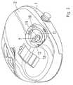
- FIG. 1shows an inner cup portion included in the ear cup, as well as a unit consisting of a microphone and bracket prior to the mounting of the microphone;
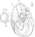
- FIG. 2is a view corresponding to that of FIG. 1 of the ear cup, with an outer cup portion mounted in position;
- FIG. 3shows the ear cup according to FIG. 2 prior to the mounting of a windshield, a frame for retaining the windshield being shown prior to the mounting of the frame;
- FIG. 4is a horizontal cross section through a complete ear cup on a level with the microphone
- FIG. 5is a straight side elevation of the frame illustrated in FIG. 3 ;
- FIG. 6shows the frame according to FIG. 5 seen from the right in this Figure
- FIG. 7Ashows the bracket for the microphone seen straight from the front
- FIG. 7Bshows the bracket according to FIG. 7A seen from the side
- FIG. 7Cshows the bracket according to FIGS. 7A and 7B seen in the opposite direction compared with FIG. 7A .
- FIGS. 1 to 3show the right-hand one of the two ear cups included in a complete hearing protection unit.
- the ear cupcomprises a first or inner cup portion 1 and a second or outer cup portion 2 .
- the inner cup portion 1has, on its outside, an inward bulge 3 which is associated with a pocket 4 , which is thus open towards the inward bulge 3 .
- Both the inward bulge 3 and the pocket 4are closed towards the inside of the inner cup portion.
- the pocket 4has two opposingly located recesses 5 and 6 .
- a microphone 7is disposed in a bracket 8 which has wings 9 and 10 projecting in opposing directions, the wings lying in a common plane which intersects the longitudinal axis 19 ( FIG. 7B ) of the bracket at an acute angle. Both of the wings 9 and 10 are formed so as to fit in the recesses 5 and 6 , respectively, when the bracket 8 is displaced downwards in the pocket 4 .
- the microphonewill be positionally fixed in the pocket 4 so that its sound receiving surface is turned to face towards the inward bulge 3 and is freely exposed to it. The sound receiving surface of the microphone 7 thus ‘looks’ along the axis 19 .
- the direction of the pocket 4is such that the centre axis 19 of the bracket 8 , when the ear cup is located in a position of use, will extend obliquely out to the right in a forward direction in relation to the wearer of the hearing protection unit (this applies to the right-hand ear cup).
- the corresponding axispoints forwards and obliquely outwards to the left.
- the microphone 7 , the bracket 8 and the connection conductor or lead of the microphoneare joined together to form an integrated unit and, from the pocket 4 , a conductor receiving space extends to a position on the outside of the inner cup portion 1 , where electric connection for the microphone 7 is to be put into effect.
- FIG. 4shows in cross section how the microphone 7 is disposed interiorly in the bracket 8 and this in turn is positioned in the pocket 4 on the outside of the inner cup portion 1 . It will also be apparent from FIG. 4 that the outer cup portion 2 covers the inner cup portion on its outside.
- the outer cup portion 2has been mounted on the inner cup portion 1 and it will be apparent that the outer cup portion 2 completely covers the whole of the outside of the inner cup portion 1 and that the outer cup portion 2 has, on its outside, an inward bulge 11 , which is surrounded by a countersunk flange 12 which is open towards the outer surface of the outer cup portion 2 . (The purpose of this flange will be described in greater detail below). At the inner end of the inward bulge 11 , there is an opening 13 which lies in front of and preferably straight in line with the microphone 7 .
- the size of the openingis at least as large as the transverse dimension of the microphone 7 , but preferably slightly larger, however not so large that the outer diameter of the bracket 8 is reached or surpassed.
- the microphone 7‘looks to the front’ through the opening 13 in the bottom or the inner end of the inward bulge 11 .
- the inward bulge 11 on the inside of the outer cup portion 2forms an arched funnel-shaped cavity 14 where the microphone 7 is located at the inner end of the cavity or its bottom.
- the surface on the outside of the outer cup portion 2 defining the cavity 14may be made hemispherical or at least approximately hemispherical.
- the above-mentioned flange 12 around the inward bulge 11 in the outer cup portion 2is intended for accommodating a windshield 15 (see FIG. 4 ) which is produced from a porous material, preferably a foamed material with open pores.
- the cavity 14is located thus on the inside of the windshield 15 and between this and the microphone 7 .
- a mounting frameis shown in FIG. 4 , which extends along the periphery of the windshield on its outside and whose purpose is to secure the windshield in the flange 12 .
- Parts of the mounting frameare shown in FIGS. 5 and 6 .
- the mounting framehas snap catches 17 which snap into engagement in corresponding catches in the outer cup portion 2 .
- a soiled or otherwise destroyed windshield 15may readily be replaceable so that, when necessary, it can be renewed.
- the inward bulge 3 shown in FIG. 1 in the inner cup portion 1has no acoustic effect on the subject matter of the present invention, but merely serves the purpose of providing room for the inward bulge 11 in the outer cup portion 2 .
- FIGS. 7A , 7 B and 7 Cshow the microphone bracket 8 and it will be clearly apparent from FIG. 7B how the wings 9 and 10 lie in a plane making an angle with the longitudinal axis 19 of the microphone bracket.
- the microphone bracket 8is suitably manufactured from an elastic, yieldable material that may have an inherent noise damping effect but has on its outside grooves 20 which form an acoustic break between the microphone and the wall surfaces defining the pocket 4 in the inner cup portion 1 . This entails that the microphone will be less sensitive to such noise as may occur if the ear cup were to come into contact with foreign matter or be subjected to impact or scratching.
- the grooves 20realise an air gap between the outside of the microphone bracket 8 and the above-mentioned defining surfaces in the pocket 4 .
- connection conductors of the microphoneare integrated into a unit.
- the connection conductorsexit in such instance via an opening 21 in the rear/lower end of the bracket.
Landscapes
- Health & Medical Sciences (AREA)
- Physics & Mathematics (AREA)
- Acoustics & Sound (AREA)
- Engineering & Computer Science (AREA)
- Life Sciences & Earth Sciences (AREA)
- Biomedical Technology (AREA)
- Veterinary Medicine (AREA)
- Otolaryngology (AREA)
- Psychology (AREA)
- Signal Processing (AREA)
- Biophysics (AREA)
- Heart & Thoracic Surgery (AREA)
- Vascular Medicine (AREA)
- Animal Behavior & Ethology (AREA)
- General Health & Medical Sciences (AREA)
- Public Health (AREA)
- General Physics & Mathematics (AREA)
- Optics & Photonics (AREA)
- Details Of Audible-Bandwidth Transducers (AREA)
- Telephone Set Structure (AREA)
- Purses, Travelling Bags, Baskets, Or Suitcases (AREA)
- Headphones And Earphones (AREA)
Abstract
Description
Claims (12)
Applications Claiming Priority (4)
| Application Number | Priority Date | Filing Date | Title |
|---|---|---|---|
| SE0500983 | 2005-04-29 | ||
| SE0500983-2 | 2005-04-29 | ||
| SE0500983ASE528515C2 (en) | 2005-04-29 | 2005-04-29 | Earphone with microphone device |
| PCT/SE2006/000498WO2006118516A1 (en) | 2005-04-29 | 2006-04-26 | Ear cup with microphone device |
Publications (2)
| Publication Number | Publication Date |
|---|---|
| US20080187150A1 US20080187150A1 (en) | 2008-08-07 |
| US8224011B2true US8224011B2 (en) | 2012-07-17 |
Family
ID=37308229
Family Applications (1)
| Application Number | Title | Priority Date | Filing Date |
|---|---|---|---|
| US11/912,608Active2029-04-13US8224011B2 (en) | 2005-04-29 | 2006-04-26 | Ear cup with microphone device |
Country Status (10)
| Country | Link |
|---|---|
| US (1) | US8224011B2 (en) |
| EP (1) | EP1877016B1 (en) |
| CN (1) | CN100563609C (en) |
| AU (1) | AU2006241532B2 (en) |
| NO (1) | NO20074969L (en) |
| PL (1) | PL1877016T3 (en) |
| RU (1) | RU2007144203A (en) |
| SE (1) | SE528515C2 (en) |
| TR (1) | TR201808490T4 (en) |
| WO (1) | WO2006118516A1 (en) |
Cited By (3)
| Publication number | Priority date | Publication date | Assignee | Title |
|---|---|---|---|---|
| US20100303270A1 (en)* | 2009-06-01 | 2010-12-02 | Red Tail Hawk Corporation | Ear Defender With Concha Simulator |
| US9084053B2 (en) | 2013-01-11 | 2015-07-14 | Red Tail Hawk Corporation | Microphone environmental protection device |
| US9900735B2 (en) | 2015-12-18 | 2018-02-20 | Federal Signal Corporation | Communication systems |
Families Citing this family (7)
| Publication number | Priority date | Publication date | Assignee | Title |
|---|---|---|---|---|
| EP2330829B1 (en)* | 2009-12-02 | 2012-11-14 | GN Netcom A/S | A communication headset with a circumferential microphone slot |
| JP2011147103A (en) | 2009-12-15 | 2011-07-28 | Canon Inc | Audio signal processing device |
| KR102022401B1 (en)* | 2013-09-24 | 2019-09-18 | 현대모비스 주식회사 | Microphone for vehicle |
| US10729587B2 (en)* | 2016-05-11 | 2020-08-04 | Hellberg Safety Ab | Hearing protector and data transmission device |
| CN109309889B (en)* | 2018-09-30 | 2020-08-11 | 歌尔科技有限公司 | Sound acquisition equipment and signal processing method, device and equipment thereof |
| EP4033776B1 (en)* | 2019-05-24 | 2025-04-30 | Honeywell International Inc. | Hearing protection devices, noise exposure sensors therefor, and sensor housings and associated methods for the same |
| CN113287325A (en)* | 2020-08-24 | 2021-08-20 | 深圳市大疆创新科技有限公司 | Windproof structure, handle holder and holder set |
Citations (68)
| Publication number | Priority date | Publication date | Assignee | Title |
|---|---|---|---|---|
| US3087028A (en) | 1960-02-24 | 1963-04-23 | Bonnin Louis Ernest | Head mounting for contact microphones |
| US3306991A (en) | 1963-06-04 | 1967-02-28 | Homer J Wood | Protective hearing aid |
| US3394226A (en) | 1963-08-19 | 1968-07-23 | Daniel E. Andrews Jr. | Special purpose hearing aid |
| GB1160431A (en) | 1966-05-04 | 1969-08-06 | Mini Of Technology London | Ear Defenders. |
| US3529102A (en)* | 1965-03-26 | 1970-09-15 | Danavox Int As | Arrangement in hearing aids especially for being placed in the ear |
| GB1289993A (en) | 1969-08-07 | 1972-09-20 | ||
| US3869584A (en) | 1972-06-22 | 1975-03-04 | Int Standard Electric Corp | Headset |
| US3890474A (en) | 1972-05-17 | 1975-06-17 | Raymond C Glicksberg | Sound amplitude limiters |
| US3947646A (en)* | 1974-10-11 | 1976-03-30 | Olympus Optical Company Ltd. | Resilient microphone mounting |
| US3952158A (en) | 1974-08-26 | 1976-04-20 | Kyle Gordon L | Ear protection and hearing device |
| US4025734A (en) | 1976-07-27 | 1977-05-24 | Harry Aloupis | Ambient noise shielded ear transceiver |
| US4064362A (en) | 1976-09-13 | 1977-12-20 | David Richard Williams | Hearing protector |
| US4087653A (en) | 1975-12-17 | 1978-05-02 | Gentex Corporation | Sound attenuating earcup assembly provided with receivers and contact microphone |
| US4088849A (en) | 1975-09-30 | 1978-05-09 | Victor Company Of Japan, Limited | Headphone unit incorporating microphones for binaural recording |
| US4150262A (en) | 1974-11-18 | 1979-04-17 | Hiroshi Ono | Piezoelectric bone conductive in ear voice sounds transmitting and receiving apparatus |
| US4302635A (en) | 1980-01-04 | 1981-11-24 | Koss Corporation | Headphone construction |
| US4455675A (en) | 1982-04-28 | 1984-06-19 | Bose Corporation | Headphoning |
| US4588868A (en) | 1984-07-12 | 1986-05-13 | Avicom International, Inc. | Headset |
| US4644581A (en) | 1985-06-27 | 1987-02-17 | Bose Corporation | Headphone with sound pressure sensing means |
| WO1987004065A1 (en) | 1986-01-03 | 1987-07-16 | Trompler Lyle D | Noise limiting circuit for earmuffs |
| US4833719A (en) | 1986-03-07 | 1989-05-23 | Centre National De La Recherche Scientifique | Method and apparatus for attentuating external origin noise reaching the eardrum, and for improving intelligibility of electro-acoustic communications |
| US4867149A (en) | 1985-03-29 | 1989-09-19 | Cabot Corporation | Earplugs |
| US4887693A (en)* | 1987-06-24 | 1989-12-19 | Shure Brothers, Inc. | Wind and breath noise protector for microphones |
| US4928311A (en) | 1986-01-03 | 1990-05-22 | Trompler Lyle D | Noise limiting circuit for earmuffs |
| US4985925A (en) | 1988-06-24 | 1991-01-15 | Sensor Electronics, Inc. | Active noise reduction system |
| WO1991007153A1 (en) | 1989-11-17 | 1991-05-30 | Panacoustics A/S | A hearing protector set |
| EP0465971A2 (en) | 1990-07-13 | 1992-01-15 | CAIRNS & BROTHER INCORPORATED | Combination head-protective helmet & communications system |
| US5125032A (en) | 1988-12-02 | 1992-06-23 | Erwin Meister | Talk/listen headset |
| US5182774A (en)* | 1990-07-20 | 1993-01-26 | Telex Communications, Inc. | Noise cancellation headset |
| US5251263A (en) | 1992-05-22 | 1993-10-05 | Andrea Electronics Corporation | Adaptive noise cancellation and speech enhancement system and apparatus therefor |
| US5404577A (en) | 1990-07-13 | 1995-04-04 | Cairns & Brother Inc. | Combination head-protective helmet & communications system |
| US5450496A (en) | 1993-07-30 | 1995-09-12 | Acs Communications, Inc. | Communications headset having a detachable receiver capsule and cable pivot |
| WO1996008004A1 (en) | 1994-09-02 | 1996-03-14 | Minnesota Mining And Manufacturing Company | Directional ear device with adaptive bandwidth and gain control |
| US5631965A (en) | 1992-06-19 | 1997-05-20 | Chang; Joseph S. | Hearing protector |
| WO1997028742A1 (en) | 1993-12-03 | 1997-08-14 | Hal Greenberger | Noise-reducing stethoscope |
| US5675658A (en) | 1995-07-27 | 1997-10-07 | Brittain; Thomas Paige | Active noise reduction headset |
| US5701355A (en)* | 1996-08-05 | 1997-12-23 | Motorola, Inc. | Microphone for a two way radio |
| US5870483A (en)* | 1996-02-27 | 1999-02-09 | National Research Council Of Canada | Sound insulating cap for sound level meters |
| EP0967592A2 (en) | 1993-06-23 | 1999-12-29 | Noise Cancellation Technologies, Inc. | Variable gain active noise cancellation system with improved residual noise sensing |
| DE10117704A1 (en) | 2001-04-09 | 2001-09-06 | Hoergeraete Kind Gmbh U Co Kg | Ear defenders with pump effect compensation, have active compensation system for reducing sound pressure caused by acceleration against user's head |
| US20010046304A1 (en) | 2000-04-24 | 2001-11-29 | Rast Rodger H. | System and method for selective control of acoustic isolation in headsets |
| WO2002017838A1 (en) | 2000-09-01 | 2002-03-07 | Nacre As | Ear protection with verification device |
| US20020055374A1 (en)* | 2000-05-05 | 2002-05-09 | Adrian Rivera | Pneumatic cell phone speaker assembly |
| US20020080987A1 (en) | 1997-08-15 | 2002-06-27 | Christer Almqvist | Arrangement in acoustic headsets |
| US6412593B1 (en) | 1998-03-18 | 2002-07-02 | Nct Group, Inc. | Cushioned earphones |
| US20020106100A1 (en)* | 2000-12-07 | 2002-08-08 | Eric Kao | Wireless hanging type earphone |
| US6463157B1 (en) | 1998-10-06 | 2002-10-08 | Analytical Engineering, Inc. | Bone conduction speaker and microphone |
| US6567525B1 (en) | 1994-06-17 | 2003-05-20 | Bose Corporation | Supra aural active noise reduction headphones |
| US6574345B1 (en)* | 2002-03-22 | 2003-06-03 | Kuan-Di Huang | Structure of a wearable and hands free earphone |
| US6597792B1 (en)* | 1999-07-15 | 2003-07-22 | Bose Corporation | Headset noise reducing |
| US6704428B1 (en) | 1999-03-05 | 2004-03-09 | Michael Wurtz | Automatic turn-on and turn-off control for battery-powered headsets |
| US6748087B1 (en) | 1995-09-07 | 2004-06-08 | Nct Group, Inc. | Headset with ear cushion and means for limiting the compression of the cushion |
| US20040125976A1 (en) | 2002-12-30 | 2004-07-01 | Reneker Brian Scott | Headphones or earmuffs with a user operated mechanical device that controls the volume of exterior sound entering the ear of the user |
| US6801629B2 (en) | 2000-12-22 | 2004-10-05 | Sonic Innovations, Inc. | Protective hearing devices with multi-band automatic amplitude control and active noise attenuation |
| WO2005051255A1 (en) | 2003-11-27 | 2005-06-09 | Peltor Ab | Hearing protector |
| US6970571B2 (en) | 2002-02-02 | 2005-11-29 | Jackson Products, Inc. | Low cost hearing protection device |
| EP1629808A1 (en) | 2004-08-25 | 2006-03-01 | Phonak Ag | Earplug and method for manufacturing the same |
| US20060050914A1 (en)* | 1998-11-25 | 2006-03-09 | Insound Medical, Inc. | Sealing retainer for extended wear hearing devices |
| WO2006118514A1 (en) | 2005-04-29 | 2006-11-09 | Peltor Ab | Ear cup |
| US7245735B2 (en) | 2004-04-02 | 2007-07-17 | David Han | Earmuff structure for headset or ear protector |
| US7308106B2 (en) | 2004-05-17 | 2007-12-11 | Adaptive Technologies, Inc. | System and method for optimized active controller design in an ANR system |
| US20080011084A1 (en) | 2006-07-13 | 2008-01-17 | Phonak Ag | Method for in-situ measuring of acoustic attenuation and system therefor |
| US7327850B2 (en) | 2003-07-15 | 2008-02-05 | Bose Corporation | Supplying electrical power |
| US7391878B2 (en) | 2005-01-12 | 2008-06-24 | Sheng-Hsin Liao | Earphone device having composite functions |
| GB2445984A (en) | 2007-01-25 | 2008-07-30 | Sonaptic Ltd | Feedforward ambient noise reduction |
| WO2008099137A1 (en) | 2007-02-16 | 2008-08-21 | Wolfson Microelectronics Plc | Ear- worn speaker-carrying devices |
| WO2008113822A2 (en) | 2007-03-19 | 2008-09-25 | Sennheiser Electronic Gmbh & Co. Kg | Headset |
| US8054985B2 (en) | 2003-11-03 | 2011-11-08 | 3M Innovative Properties Company | Low sound attenuating hearing protection device with filter arrangement |
Family Cites Families (3)
| Publication number | Priority date | Publication date | Assignee | Title |
|---|---|---|---|---|
| SE505203C2 (en)* | 1995-02-01 | 1997-07-14 | Bilsom Ab | A method for changing the sound attenuation of an earmuff as well as the earmuff according to the method |
| CN2285039Y (en)* | 1996-12-02 | 1998-06-24 | 怡利电子工业股份有限公司 | Storage unit for earphone and microphone cables for hands-free handsets |
| JP3655146B2 (en)* | 1999-10-08 | 2005-06-02 | 本田技研工業株式会社 | Air-fuel ratio control device for multi-cylinder internal combustion engine |
- 2005
- 2005-04-29SESE0500983Apatent/SE528515C2/enunknown
- 2006
- 2006-04-26RURU2007144203/14Apatent/RU2007144203A/ennot_activeApplication Discontinuation
- 2006-04-26AUAU2006241532Apatent/AU2006241532B2/ennot_activeExpired - Fee Related
- 2006-04-26USUS11/912,608patent/US8224011B2/enactiveActive
- 2006-04-26CNCNB2006800147141Apatent/CN100563609C/ennot_activeExpired - Fee Related
- 2006-04-26EPEP06733354.2Apatent/EP1877016B1/ennot_activeNot-in-force
- 2006-04-26WOPCT/SE2006/000498patent/WO2006118516A1/enactiveApplication Filing
- 2006-04-26TRTR2018/08490Tpatent/TR201808490T4/enunknown
- 2006-04-26PLPL06733354Tpatent/PL1877016T3/enunknown
- 2007
- 2007-10-04NONO20074969Apatent/NO20074969L/ennot_activeApplication Discontinuation
Patent Citations (73)
| Publication number | Priority date | Publication date | Assignee | Title |
|---|---|---|---|---|
| US3087028A (en) | 1960-02-24 | 1963-04-23 | Bonnin Louis Ernest | Head mounting for contact microphones |
| US3306991A (en) | 1963-06-04 | 1967-02-28 | Homer J Wood | Protective hearing aid |
| US3394226A (en) | 1963-08-19 | 1968-07-23 | Daniel E. Andrews Jr. | Special purpose hearing aid |
| US3529102A (en)* | 1965-03-26 | 1970-09-15 | Danavox Int As | Arrangement in hearing aids especially for being placed in the ear |
| GB1160431A (en) | 1966-05-04 | 1969-08-06 | Mini Of Technology London | Ear Defenders. |
| GB1289993A (en) | 1969-08-07 | 1972-09-20 | ||
| US3890474A (en) | 1972-05-17 | 1975-06-17 | Raymond C Glicksberg | Sound amplitude limiters |
| US3869584A (en) | 1972-06-22 | 1975-03-04 | Int Standard Electric Corp | Headset |
| US3952158A (en) | 1974-08-26 | 1976-04-20 | Kyle Gordon L | Ear protection and hearing device |
| US3947646A (en)* | 1974-10-11 | 1976-03-30 | Olympus Optical Company Ltd. | Resilient microphone mounting |
| US4150262A (en) | 1974-11-18 | 1979-04-17 | Hiroshi Ono | Piezoelectric bone conductive in ear voice sounds transmitting and receiving apparatus |
| US4088849A (en) | 1975-09-30 | 1978-05-09 | Victor Company Of Japan, Limited | Headphone unit incorporating microphones for binaural recording |
| US4087653A (en) | 1975-12-17 | 1978-05-02 | Gentex Corporation | Sound attenuating earcup assembly provided with receivers and contact microphone |
| US4025734A (en) | 1976-07-27 | 1977-05-24 | Harry Aloupis | Ambient noise shielded ear transceiver |
| US4064362A (en) | 1976-09-13 | 1977-12-20 | David Richard Williams | Hearing protector |
| US4302635A (en) | 1980-01-04 | 1981-11-24 | Koss Corporation | Headphone construction |
| US4455675A (en) | 1982-04-28 | 1984-06-19 | Bose Corporation | Headphoning |
| US4588868A (en) | 1984-07-12 | 1986-05-13 | Avicom International, Inc. | Headset |
| US4867149A (en) | 1985-03-29 | 1989-09-19 | Cabot Corporation | Earplugs |
| US4644581A (en) | 1985-06-27 | 1987-02-17 | Bose Corporation | Headphone with sound pressure sensing means |
| WO1987004065A1 (en) | 1986-01-03 | 1987-07-16 | Trompler Lyle D | Noise limiting circuit for earmuffs |
| US4928311A (en) | 1986-01-03 | 1990-05-22 | Trompler Lyle D | Noise limiting circuit for earmuffs |
| US4833719A (en) | 1986-03-07 | 1989-05-23 | Centre National De La Recherche Scientifique | Method and apparatus for attentuating external origin noise reaching the eardrum, and for improving intelligibility of electro-acoustic communications |
| US4887693A (en)* | 1987-06-24 | 1989-12-19 | Shure Brothers, Inc. | Wind and breath noise protector for microphones |
| US4985925A (en) | 1988-06-24 | 1991-01-15 | Sensor Electronics, Inc. | Active noise reduction system |
| US5125032A (en) | 1988-12-02 | 1992-06-23 | Erwin Meister | Talk/listen headset |
| WO1991007153A1 (en) | 1989-11-17 | 1991-05-30 | Panacoustics A/S | A hearing protector set |
| US5404577A (en) | 1990-07-13 | 1995-04-04 | Cairns & Brother Inc. | Combination head-protective helmet & communications system |
| EP0465971A2 (en) | 1990-07-13 | 1992-01-15 | CAIRNS & BROTHER INCORPORATED | Combination head-protective helmet & communications system |
| US5182774A (en)* | 1990-07-20 | 1993-01-26 | Telex Communications, Inc. | Noise cancellation headset |
| US5251263A (en) | 1992-05-22 | 1993-10-05 | Andrea Electronics Corporation | Adaptive noise cancellation and speech enhancement system and apparatus therefor |
| US5631965A (en) | 1992-06-19 | 1997-05-20 | Chang; Joseph S. | Hearing protector |
| EP0967592A2 (en) | 1993-06-23 | 1999-12-29 | Noise Cancellation Technologies, Inc. | Variable gain active noise cancellation system with improved residual noise sensing |
| US5450496A (en) | 1993-07-30 | 1995-09-12 | Acs Communications, Inc. | Communications headset having a detachable receiver capsule and cable pivot |
| WO1997028742A1 (en) | 1993-12-03 | 1997-08-14 | Hal Greenberger | Noise-reducing stethoscope |
| US6567525B1 (en) | 1994-06-17 | 2003-05-20 | Bose Corporation | Supra aural active noise reduction headphones |
| WO1996008004A1 (en) | 1994-09-02 | 1996-03-14 | Minnesota Mining And Manufacturing Company | Directional ear device with adaptive bandwidth and gain control |
| US5550923A (en) | 1994-09-02 | 1996-08-27 | Minnesota Mining And Manufacturing Company | Directional ear device with adaptive bandwidth and gain control |
| US5675658A (en) | 1995-07-27 | 1997-10-07 | Brittain; Thomas Paige | Active noise reduction headset |
| US6748087B1 (en) | 1995-09-07 | 2004-06-08 | Nct Group, Inc. | Headset with ear cushion and means for limiting the compression of the cushion |
| US5870483A (en)* | 1996-02-27 | 1999-02-09 | National Research Council Of Canada | Sound insulating cap for sound level meters |
| US5701355A (en)* | 1996-08-05 | 1997-12-23 | Motorola, Inc. | Microphone for a two way radio |
| US6965681B2 (en) | 1997-08-15 | 2005-11-15 | Peltor Ab | Arrangement in acoustic headsets |
| US20020080987A1 (en) | 1997-08-15 | 2002-06-27 | Christer Almqvist | Arrangement in acoustic headsets |
| US6412593B1 (en) | 1998-03-18 | 2002-07-02 | Nct Group, Inc. | Cushioned earphones |
| US6463157B1 (en) | 1998-10-06 | 2002-10-08 | Analytical Engineering, Inc. | Bone conduction speaker and microphone |
| US7664282B2 (en) | 1998-11-25 | 2010-02-16 | Insound Medical, Inc. | Sealing retainer for extended wear hearing devices |
| US20060050914A1 (en)* | 1998-11-25 | 2006-03-09 | Insound Medical, Inc. | Sealing retainer for extended wear hearing devices |
| US6704428B1 (en) | 1999-03-05 | 2004-03-09 | Michael Wurtz | Automatic turn-on and turn-off control for battery-powered headsets |
| US6597792B1 (en)* | 1999-07-15 | 2003-07-22 | Bose Corporation | Headset noise reducing |
| US20010046304A1 (en) | 2000-04-24 | 2001-11-29 | Rast Rodger H. | System and method for selective control of acoustic isolation in headsets |
| US20020055374A1 (en)* | 2000-05-05 | 2002-05-09 | Adrian Rivera | Pneumatic cell phone speaker assembly |
| US6631279B2 (en) | 2000-05-05 | 2003-10-07 | Adrian Rivera | Pneumatic cell phone speaker assembly |
| WO2002017838A1 (en) | 2000-09-01 | 2002-03-07 | Nacre As | Ear protection with verification device |
| US20020106100A1 (en)* | 2000-12-07 | 2002-08-08 | Eric Kao | Wireless hanging type earphone |
| US6801629B2 (en) | 2000-12-22 | 2004-10-05 | Sonic Innovations, Inc. | Protective hearing devices with multi-band automatic amplitude control and active noise attenuation |
| DE10117704A1 (en) | 2001-04-09 | 2001-09-06 | Hoergeraete Kind Gmbh U Co Kg | Ear defenders with pump effect compensation, have active compensation system for reducing sound pressure caused by acceleration against user's head |
| US6970571B2 (en) | 2002-02-02 | 2005-11-29 | Jackson Products, Inc. | Low cost hearing protection device |
| US6574345B1 (en)* | 2002-03-22 | 2003-06-03 | Kuan-Di Huang | Structure of a wearable and hands free earphone |
| US20040125976A1 (en) | 2002-12-30 | 2004-07-01 | Reneker Brian Scott | Headphones or earmuffs with a user operated mechanical device that controls the volume of exterior sound entering the ear of the user |
| US7327850B2 (en) | 2003-07-15 | 2008-02-05 | Bose Corporation | Supplying electrical power |
| US8054985B2 (en) | 2003-11-03 | 2011-11-08 | 3M Innovative Properties Company | Low sound attenuating hearing protection device with filter arrangement |
| US20070274529A1 (en) | 2003-11-27 | 2007-11-29 | Henrik Nordin | Hearing Protector |
| WO2005051255A1 (en) | 2003-11-27 | 2005-06-09 | Peltor Ab | Hearing protector |
| US7245735B2 (en) | 2004-04-02 | 2007-07-17 | David Han | Earmuff structure for headset or ear protector |
| US7308106B2 (en) | 2004-05-17 | 2007-12-11 | Adaptive Technologies, Inc. | System and method for optimized active controller design in an ANR system |
| EP1629808A1 (en) | 2004-08-25 | 2006-03-01 | Phonak Ag | Earplug and method for manufacturing the same |
| US7391878B2 (en) | 2005-01-12 | 2008-06-24 | Sheng-Hsin Liao | Earphone device having composite functions |
| WO2006118514A1 (en) | 2005-04-29 | 2006-11-09 | Peltor Ab | Ear cup |
| US20080011084A1 (en) | 2006-07-13 | 2008-01-17 | Phonak Ag | Method for in-situ measuring of acoustic attenuation and system therefor |
| GB2445984A (en) | 2007-01-25 | 2008-07-30 | Sonaptic Ltd | Feedforward ambient noise reduction |
| WO2008099137A1 (en) | 2007-02-16 | 2008-08-21 | Wolfson Microelectronics Plc | Ear- worn speaker-carrying devices |
| WO2008113822A2 (en) | 2007-03-19 | 2008-09-25 | Sennheiser Electronic Gmbh & Co. Kg | Headset |
Non-Patent Citations (1)
| Title |
|---|
| International Search Report; PCT/SE2006/000498; Aug. 8, 2006. |
Cited By (7)
| Publication number | Priority date | Publication date | Assignee | Title |
|---|---|---|---|---|
| US20100303270A1 (en)* | 2009-06-01 | 2010-12-02 | Red Tail Hawk Corporation | Ear Defender With Concha Simulator |
| US8638963B2 (en)* | 2009-06-01 | 2014-01-28 | Red Tail Hawk Corporation | Ear defender with concha simulator |
| US9473846B2 (en) | 2009-06-01 | 2016-10-18 | Red Tail Hawk Corporation | Ear defender with concha simulator |
| US9924261B2 (en) | 2009-06-01 | 2018-03-20 | Red Tail Hawk Corporation | Ear defender with concha simulator |
| US9084053B2 (en) | 2013-01-11 | 2015-07-14 | Red Tail Hawk Corporation | Microphone environmental protection device |
| US9609411B2 (en) | 2013-01-11 | 2017-03-28 | Red Tail Hawk Corporation | Microphone environmental protection device |
| US9900735B2 (en) | 2015-12-18 | 2018-02-20 | Federal Signal Corporation | Communication systems |
Also Published As
| Publication number | Publication date |
|---|---|
| SE0500983L (en) | 2006-10-30 |
| SE528515C2 (en) | 2006-12-05 |
| EP1877016A1 (en) | 2008-01-16 |
| TR201808490T4 (en) | 2018-07-23 |
| NO20074969L (en) | 2008-01-03 |
| US20080187150A1 (en) | 2008-08-07 |
| EP1877016B1 (en) | 2018-04-04 |
| AU2006241532B2 (en) | 2012-02-16 |
| AU2006241532A1 (en) | 2006-11-09 |
| WO2006118516A1 (en) | 2006-11-09 |
| EP1877016A4 (en) | 2014-12-10 |
| CN100563609C (en) | 2009-12-02 |
| RU2007144203A (en) | 2009-06-10 |
| PL1877016T3 (en) | 2018-10-31 |
| CN101166490A (en) | 2008-04-23 |
Similar Documents
| Publication | Publication Date | Title |
|---|---|---|
| US8224011B2 (en) | Ear cup with microphone device | |
| USRE48921E1 (en) | Audio device comprising a microphone | |
| ES2973757T3 (en) | Glasses comprising ear devices | |
| AU2014338773B2 (en) | Earpiece | |
| US8223984B2 (en) | System for forming a hearing protector, ear cup in such a system, and hearing protector formed by such a system | |
| RU2395261C2 (en) | Headphones | |
| US10897669B2 (en) | Two layer microphone protection | |
| US10200799B2 (en) | Hearing device with sealed microphone opening | |
| US12155984B2 (en) | Open-ear headphone | |
| JP4555577B2 (en) | Microphone and battery structure for hearing aids | |
| WO2020081656A1 (en) | Active noise reduction earphone | |
| CN118264951B (en) | Earphone and audio device | |
| CN106165450B (en) | ITE hearing aids and methods of making ITE hearing aids | |
| CN106375894A (en) | Noise Canceling Headphones | |
| US12133038B2 (en) | Acoustic vent and protective membrane | |
| KR102312005B1 (en) | Earphone with microphone | |
| CN210042156U (en) | Novel waterproof bone conduction bluetooth headset | |
| US12244990B2 (en) | Acoustic vent and protective membrane | |
| CN223309942U (en) | Headphones and audio devices | |
| WO2024243791A1 (en) | Wind noise reduction earphone | |
| ES3014952A1 (en) | WIRELESS COMMUNICATOR DEVICE INTEGRABLE WITHIN A HELMET (Machine-translation by Google Translate, not legally binding) | |
| HK1140089A (en) | Speaker shell |
Legal Events
| Date | Code | Title | Description |
|---|---|---|---|
| AS | Assignment | Owner name:PELTOR AB, SWEDEN Free format text:ASSIGNMENT OF ASSIGNORS INTEREST;ASSIGNOR:HERINGSLACK, HENRIK;REEL/FRAME:020016/0778 Effective date:20070923 | |
| AS | Assignment | Owner name:3M SVENSKA AKTIEBOLAG, SWEDEN Free format text:CHANGE OF NAME;ASSIGNOR:PELTOR AKTIEBOLAG;REEL/FRAME:022798/0096 Effective date:20090112 Owner name:3M SVENSKA AKTIEBOLAG,SWEDEN Free format text:CHANGE OF NAME;ASSIGNOR:PELTOR AKTIEBOLAG;REEL/FRAME:022798/0096 Effective date:20090112 | |
| STCF | Information on status: patent grant | Free format text:PATENTED CASE | |
| CC | Certificate of correction | ||
| FPAY | Fee payment | Year of fee payment:4 | |
| AS | Assignment | Owner name:3M INNOVATIVE PROPERTIES COMPANY, MINNESOTA Free format text:ASSIGNMENT OF ASSIGNORS INTEREST;ASSIGNOR:3M SVENSKA AKTIEBOLAG;REEL/FRAME:040431/0972 Effective date:20161111 | |
| MAFP | Maintenance fee payment | Free format text:PAYMENT OF MAINTENANCE FEE, 8TH YEAR, LARGE ENTITY (ORIGINAL EVENT CODE: M1552); ENTITY STATUS OF PATENT OWNER: LARGE ENTITY Year of fee payment:8 | |
| MAFP | Maintenance fee payment | Free format text:PAYMENT OF MAINTENANCE FEE, 12TH YEAR, LARGE ENTITY (ORIGINAL EVENT CODE: M1553); ENTITY STATUS OF PATENT OWNER: LARGE ENTITY Year of fee payment:12 |