US8223821B2 - Uplink signal detection in RF repeaters - Google Patents
Uplink signal detection in RF repeatersDownload PDFInfo
- Publication number
- US8223821B2 US8223821B2US12/491,371US49137109AUS8223821B2US 8223821 B2US8223821 B2US 8223821B2US 49137109 AUS49137109 AUS 49137109AUS 8223821 B2US8223821 B2US 8223821B2
- Authority
- US
- United States
- Prior art keywords
- phase
- signal
- baseband signal
- quadrature
- short code
- Prior art date
- Legal status (The legal status is an assumption and is not a legal conclusion. Google has not performed a legal analysis and makes no representation as to the accuracy of the status listed.)
- Expired - Fee Related, expires
Links
Images


Classifications
- H—ELECTRICITY
- H04—ELECTRIC COMMUNICATION TECHNIQUE
- H04B—TRANSMISSION
- H04B7/00—Radio transmission systems, i.e. using radiation field
- H04B7/14—Relay systems
- H04B7/15—Active relay systems
- H04B7/155—Ground-based stations
- H04B7/15528—Control of operation parameters of a relay station to exploit the physical medium
- H04B7/15535—Control of relay amplifier gain
- H—ELECTRICITY
- H04—ELECTRIC COMMUNICATION TECHNIQUE
- H04B—TRANSMISSION
- H04B1/00—Details of transmission systems, not covered by a single one of groups H04B3/00 - H04B13/00; Details of transmission systems not characterised by the medium used for transmission
- H04B1/69—Spread spectrum techniques
- H04B1/707—Spread spectrum techniques using direct sequence modulation
- H04B1/70718—Spread spectrum techniques using direct sequence modulation with asynchronous demodulation, i.e. not requiring code synchronisation
Definitions
- the present inventionis directed generally to repeaters or signal repeating devices for wireless communications, and more particularly to an apparatus and method for detecting spread spectrum signals.
- signal repeating devicesare used to extend the coverage of the overall wireless system.
- wireless or cellular systemsconsist of a plurality of base stations that communicate with each other in an overlapping fashion, and operate to provide a defined signal coverage area for user equipment (“UE”), such as a cell phone or other wireless device.
- UEuser equipment
- coverage areasthere are often smaller, more remote areas that have very low signal reception, such as areas within buildings or areas that are otherwise obstructed.
- signal repeating devices or repeatersare utilized.
- a repeateressentially has a donor antenna that is in communication with one or more base stations.
- the repeaterreceives downlink signals from the base station, processes and amplifies those signals, and then transmits those signals through a coverage antenna into the remote area that otherwise has low signal reception or low signal power.
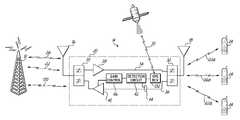
- a portion of a wireless communications system 10might include a base station 12 that communicates with a repeater 14 having a donor antenna 16 , a coverage antenna 18 , and processing electronics 20 that are configured to process and amplify the repeated signal.
- downlink wireless signals 22 from the base station 12are received by the donor antenna 16 of the repeater 14 .
- the signalsare then amplified and repeated to be transmitted through the coverage antenna 18 as downlink signals 22 a .
- the repeated downlink signals 22 aare transmitted into the remote area and are received by the UE that may include one or more wireless communication devices, such as cell phones 24 , as show in FIG. 1 .
- the UE devices 24communicate signals back to the coverage antenna 18 , and the repeated signal 26 is then transmitted as an uplink signal back to the base station 12 .
- the repeater devices 14can take many different forms.
- One particular performance characteristic of a repeateris the gain of the repeater, or the amount of amplification that the repeater provides in the repeated signal.
- Spread spectrum signalsappear generally noise-like in structure, and are thus, susceptible to the overall noise figure within the wireless system.
- the overall network capacity within a spread spectrum communication networkis a function of the interference or noise level within that network. As such, it is desirable to automatically adjust the gain, and specifically lower the gain when there is no signal traffic through the repeater. Conversely, when signal traffic is present, it would be desirable to increase the repeater gain.
- a method for detecting an IS-95 signal without knowledge of a spreading code for the IS-95 signalis provided.
- a received baseband signalis rotated through a plurality of phase-shifts.
- an in-phase component or a quadrature component of the phase-shifted baseband signalis realigned.
- the in-phase and quadrature componentsare then multiplied by a PN short code, derived from GPS time of day, to partially despread the components.
- the partially despread in-phase and quadrature componentsare multiplied and integrated over time.
- the integrated componentsare compared to a threshold value, and in response to exceeding the threshold value, the received baseband signal is identified as an IS-95 signal.
- a methodfor repeating signals between multiple sources. Signals repeated between the multiple sources are transceived with a donor antenna and a coverage antenna. The repeated signals are amplified between the antennas with an amplification circuit having a variable gain. Uplink signals are downconverted to complex baseband signals. The phase of the baseband signals is rotated through a plurality of phase shifts. Each phase shifted baseband signal is multiplied by a PN short code derived from GPS time of day. The gain may then be varied based upon the multiplied baseband signal exceeding a threshold indicating the presence of an IS-95 spread spectrum signal.
- a repeaterfor repeating signals between multiple sources.
- the repeaterinclude a donor antenna and a coverage antenna for transceiving signals that are repeated between the multiple sources.
- An amplification circuitis positioned between the donor and coverage antennas for amplifying the repeated signals.
- the amplification circuitis configured for a variable gain.
- a detection circuitis configured to obtain a PN short code derived from GPS time of day for an uplink signal received by the repeater.
- the detection circuitis operable to downconvert the uplink signal to a complex baseband signal and to rotate the baseband signal through a plurality of phase shifts.
- the detection circuitfurther multiplies each of the phase shifted baseband signals by the PN short code to partially despread the signal.
- An amplification circuitmay then vary its gain based upon the multiplied baseband signal exceeding a threshold value, indicating the presence or absence of a spread spectrum signal.
- FIG. 1is a schematic diagram of a repeater utilized within a wireless system for incorporating an embodiment of the present invention.
- FIG. 2is a circuit block diagram of a repeater incorporating one embodiment of the present invention.
- FIG. 3is a block diagram illustrating IS-95 modulation for an uplink channel.
- FIG. 4is a block diagram illustrating IS-95 modulation for a traffic channel.
- FIG. 5is a block diagram illustrating the detection of the modulated signals of FIGS. 3 and 4 .
- FIG. 6is a graph of correlation loss v. phase offset for the complex baseband signal.
- Embodiments of the present inventionare directed to a system and method for automatic gain control of a repeater utilizing detection of a spread spectrum signal to trigger the gain control.
- Embodimentsprovide a method for detecting the existence of spread spectrum wireless signals without the knowledge of the spreading codes used for transmission.
- the detection method employed in embodiments of the inventionexploits a known modulation structure of IS-95 and its relationship to GPS time of day in order to accurately detect the existence of IS-95 signals without the knowledge of the underlying spreading codes.
- the IS-95 standarduses a unique complex quadrature modulation technique for all of its physical channels for uplink transmissions from user equipment (“UE”) 24 to a base station (“BTS”) 12 as illustrated in FIG. 2 .
- UEuser equipment
- BTSbase station
- the detection methodexploits this underlying correlation of the quadrature modulation process to detect the presence of the signal buried in noise.
- An uplink signal 26 a transmitted from the UE 24may be received at detection circuitry 42 , such as in a repeater 14 , at a suitable coupling point 44 and may be downconverted from an RF signal to a complex baseband signal using a heterodyne, super heterodyne or a direct conversion receiver as well known in the art.
- antennas 16 and 18feed into respective duplexers 30 , 32 to provide frequency isolation between a downlink path 34 and an uplink path 36 .
- the signalsare amplified by one or more amplifiers or amplifier components/circuits illustrated schematically as components 38 and 40 .
- Repeater 14repeats signals between multiple signal sources, such as BTS 12 and UE 24 .
- Like reference numeralsare utilized in FIG. 2 for those components also shown in FIG. 1 .
- Repeater 14and particularly the process electronics 20 of the repeater, includes a detection circuit 42 that couples off a portion of the uplink signal 36 at a suitable coupling point 44 using an appropriate coupler.
- the detection circuit 42is configured for isolating and reviewing the uplink signal by rotating the in-phase and quadrature components of the complex baseband signal through different phase-shift rotations and de-spreading by a PN short code in order to detect the existence of a spread spectrum signal within the uplink traffic 36 .
- a gain control circuit 46is operably coupled to each of the uplink amplifier 40 for varying the gain of the uplink amplifier, and thus, varying the uplink gain of the repeater 14 based upon the rotating and despreading process and the detection of a spread spectrum signal, as provided by the detection circuit 42 .
- the detection circuit 42 and gain control circuit 46may be implemented in various different ways, such as utilizing a processor and suitable frequency up-conversion and down-conversion circuitry for processing the uplink signals 36 to implement suitable modulation/demodulation techniques as discussed herein.
- the PN short code used by the UE to spread the spectrum of the modulated signalis not unique to each UE, but rather is synchronized with GPS time of day derived from a GPS signal 30 . Therefore, knowledge of GPS time is needed in order to approximate the phase of the PN short codes. With proper time alignment and phase shift, the two components of the complex baseband signal may exhibit a significant correlation peak if an IS-95 signal is present, and thus, gain of the repeater may be adjusted accordingly with gain control circuitry 46 in the repeater 14 .
- uplink signals 26 a from a UE 24arrive at access channel 50 as information bits 52 .
- the information bitsare passed through forward error correction blocks, rate matching blocks, and interleaving blocks, shown in FIG. 3 , 54 - 60 , as would be understood by one of ordinary skill in the art.
- the signalsare multiplexed with a 64-ary Walsh code at 62 so that signals from multiple UEs 24 remain mutually orthogonal.
- the modulated signalis spread using the long code from the long code generator 64 by a logic XORing function using appropriate logic circuitry at a point 66 .
- the resulting spread signal waveformis the same at points “A” and “B” in FIG.
- a 1 ⁇ 2 PN chip delayis introduced into the Q branch at 76 by appropriate hardware, in some embodiments, in order to create quadrature diversity through Offset Quadrature Phase Shift Keying (“OQPSK”) modulation, which shifts the in-phase and quadrature components such that the in-phase and quadrature components will not change at the same time, thus minimizing large amplitude fluctuations.
- OFPSKOffset Quadrature Phase Shift Keying
- realignments other than 1 ⁇ 2 PN chipmay also be used for advances or delays to either the in-phase or quadrature components.
- the I and Q branchesare filtered with baseband filters 78 , 80 and mixed onto the carrier wave at points 82 , 84 for transmission by appropriate mixing circuitry. These signals are summed resulting in an IS-95 signal 80 , which may then be transmitted to the BTS 12 as an uplink signal.
- the repeater 14Because GPS time is known or can be readily retrieved by the repeater 14 , it is possible for the repeater 14 to know the state of the I 68 and Q 70 PN short code sequences, since these code sequences only depend on GPS time, and not on user identity. Therefore a received signal may be projected onto each of the I 68 and Q 70 PN code sequences to partially despread incoming uplink signals.
- the output energy of the detection circuit 42will be maximized, indicating the presence of a IS-95 signal at some unique phase and time offset, and thus the uplink gain of the repeater 14 may be adjusted accordingly with the gain control 46 to amplify the uplink signal with amplifier 40 and in order to retransmit this signal. For example, if the output passes a certain threshold level indicating the presence of the signal from UE 24 , then based on the signal strength the amplification may be increased. On the other hand, if the output is below some threshold, then the amplification may be turned off or lowered as desired by the user.
- modulated uplink signal wave forms 102 a , 102 b , 102 care similarly divided into in-phase (“I”) and quadrature (“Q”) branches of complex baseband signals.
- Signal waveforms 102 a , 102 b , 102 cmay include supplemental channels with the fundamental traffic channel, with each channel using a different carrier phase offset.
- Each of the modulated signal waveforms 102 a - care spread with a logic XOR function using appropriate logic circuitry at points 108 a - c , 110 a - c with I 104 a - c and Q 106 a - c PN short codes similar to the I 68 and Q 70 PN short codes in the embodiment in FIG. 3 .
- the Q branchis then delayed, 1 ⁇ 2 PN chip, for example, at 112 a - c with appropriate delay circuitry.
- both the I and Q branchesare filtered using baseband filters 114 a - c , 116 a - c .
- the filtered signalsare mixed onto a carrier wave by appropriate mixers at points 118 a - c , 120 a - c for transmission at different phases and summed.
- the resulting wave forms 122 a - care then combined into signal 124 and transmitted to as an IS-95 uplink signal to a BTS 12 .
- the detection circuitry 42acquires GPS time and tags the start time of the received RF uplink signal 26 a .
- the GPS timemay be acquired from either a downlink synchronization channel (“SCH”) 130 , or may be independently derived through a separate GPS receiver module 132 in the repeater 14 .
- the PN short code sequences for the I and Q branchesare generated from the GPS start time of the captured signal buffer.
- uplink signal collectionis started at a time t.
- the collected uplink signalis down-converted to a complex baseband signal 152 .
- the complex baseband signalis then rotated through a plurality of different phase-shifts at 154 .
- the process of detectionis repeated for each of the phase-shifted signals 156 , 158 as shown in the block diagram of detection process 150 in FIG. 5 .
- Multiple phasesare examined for peak values to try to ensure that an actual signal is present. Additionally different peaks may be found at different phases indicating different signal strengths of the signals to be used in adjusting the uplink gains.
- the in-phase signal 156 of the complex base band signalis delayed by 1 ⁇ 2 PN chip at 160 with appropriate delay circuitry in order to re-align the in-phase and quadrature components or branches of the signal.
- 1 ⁇ 2 PN chipmay also be used but the delays should correlate to the delay of the transmitting UE.
- the signals 156 , 158 on both branches of the complex baseband signalare multiplied by the corresponding I 168 and Q 170 PN short codes to partially despread the signals at points 164 , 166 , which are derived from the current approximate GPS time 162 t acquired above from either the downlink SCH 130 or GPS receiver module 132 .
- the output from the branches Z ⁇ m I (t) and Z ⁇ m Q (t)are multiplied at 172 for a certain time length, then summed and squared at 174 .
- time alignmentshould also be searched in addition to carrier phase in order to accurately detect an IS-95 uplink signal. Consequently, the method set forth above may be repeated for all time delays within each phase.
- the time delaysmay preferably be in units of no less than 1 ⁇ 2 PN chip for best performance, although other delay intervals may also be used.
- the result 176is checked against a threshold value 178 , which may be established as a function of the signal energy received.
- PN short code phase stateis determined by the known GPS time of day 162 .
- PN I (t) 168is the I-phase PN generator sequence output at GPS time t and PN Q (t) 170 is the Q-phase PN generator sequence output at GPS time t.
- Lmay be determined by the desired integration time, or signal sequence length. Therefore, the embodiments of the invention intend to maximize the solution of R ⁇ m ( ⁇ ) 176 for the values of carrier phase rotations ⁇ and time lags ⁇ .
- the traffic (“TCH”) 100 and the random access channel (“RACH”) 50are monitored to detect spread spectrum uplink activity. Either of these channels may be used for UE uplink transmission 26 a to the BTS 12 .
- the detection process for RACH activityis generally monitored at every integer multiple of the 20 ms access boundaries, per the IS-95 specification, though other time multiples may also be used.
- the PN short codes used in the detection processmay be generated on the fly using linear feedback shift registers in the detection circuit 42 in some embodiments, or may be pre-computed and stored in a memory in other embodiments.
- the complex baseband signalis phase rotated through a plurality of discrete phase-shift values starting from zero and generally using a fixed step size.
- a smaller step sizewould likely result in better detection performance; however, the computational load due to this small step size may be significant. In embodiments where computation power is available, smaller step sizes may be used. If computational load is a concern, it has been determined that an adequate performance may be achieved by phase rotating the complex signal at discrete phase values with a step size ⁇ /8, i.e. steps at 0, ⁇ /8, ⁇ /4, 3 ⁇ /8, ⁇ /2, 5 ⁇ /8, 3 ⁇ /4, 7 ⁇ /8, and ⁇ . A single value is obtained for each of the phase values, and each of the phases is evaluated to determine the maximum magnitude among all of the phase values.
- Graph 200 in FIG. 6illustrates the dB correlation loss as a function of the phase step size.
- This analysisindicates that using a phase step size of ⁇ /8 may result in a maximum loss of approximately 0.8 dB and on average about 0.4 dB. This is concluded by assuming that the actual carrier phase of the received signal is off by exactly one half of the step size, or ⁇ /16. If the step size were to be increased to ⁇ /4, the worse case correlation loss increases to approximately 3.5 dB with an average loss of about 1.75 dB, which may be unacceptably high.
- an advantage of using a lower number of phase rotation stepsis that it reduces the computational load because fewer correlations would need to be performed. But, the disadvantage of using a lower number of steps is that in order to make up for the loss and to be able to maintain the same detection performance, the correlation sequence length would need to be increased, which increases computational load.
- the selection of the required integration time L, in equation (6)is a function of the needed processing gain in order to achieve reliable detection. Analysis and simulation results have indicated that to achieve good performance of detection at ⁇ 14 dB C/I (carrier to interference ratio), 8192 chips are needed, though for other embodiments and other C/I ratios that may be acceptable, more or fewer chips may be used. More thorough analysis may be performed to quantitatively determine the probability of detection and false alarms as a function of the processing gain, which is a well-known exercise for those of ordinary skill in the art.
- R ⁇ m (t) 176 in equation (6)is checked against a threshold at 178 to determine the existence of an IS-95 spread spectrum signal.
- the thresholdis generally determined from theoretical calculations and adjusted as necessary through the use of simulations, lab testing, and field testing.
- An integration length for the time lags Lshould be optimally chosen to strike a balance between performance and computational load.
- the thresholdshould be carefully chosen so that probability of detection and false alarm meets the requirements of the system design.
Landscapes
- Engineering & Computer Science (AREA)
- Computer Networks & Wireless Communication (AREA)
- Signal Processing (AREA)
- Mobile Radio Communication Systems (AREA)
Abstract
Description
yθ
yθ
yIθ
yQθ
in order to re-align the in-phase and quadrature components that were offset at the time of transmission. The in-phase component is also multiplied by the I PN short code168, PNI(t).
Similarly, the quadrature component is multiplied by the Q PN
The PN short code phase state is determined by the known GPS time of
The value of L may be determined by the desired integration time, or signal sequence length. Therefore, the embodiments of the invention intend to maximize the solution of Rθ
Claims (20)
Priority Applications (1)
| Application Number | Priority Date | Filing Date | Title |
|---|---|---|---|
| US12/491,371US8223821B2 (en) | 2009-06-25 | 2009-06-25 | Uplink signal detection in RF repeaters |
Applications Claiming Priority (1)
| Application Number | Priority Date | Filing Date | Title |
|---|---|---|---|
| US12/491,371US8223821B2 (en) | 2009-06-25 | 2009-06-25 | Uplink signal detection in RF repeaters |
Publications (2)
| Publication Number | Publication Date |
|---|---|
| US20100329311A1 US20100329311A1 (en) | 2010-12-30 |
| US8223821B2true US8223821B2 (en) | 2012-07-17 |
Family
ID=43380697
Family Applications (1)
| Application Number | Title | Priority Date | Filing Date |
|---|---|---|---|
| US12/491,371Expired - Fee RelatedUS8223821B2 (en) | 2009-06-25 | 2009-06-25 | Uplink signal detection in RF repeaters |
Country Status (1)
| Country | Link |
|---|---|
| US (1) | US8223821B2 (en) |
Cited By (4)
| Publication number | Priority date | Publication date | Assignee | Title |
|---|---|---|---|---|
| US20110069633A1 (en)* | 2009-09-21 | 2011-03-24 | Georg Schmidt | Antenna array, network planning system, communication network and method for relaying radio signals with independently configurable beam pattern shapes using a local knowledge |
| US8693945B2 (en) | 2010-05-12 | 2014-04-08 | Andrew Llc | System and method for detecting and measuring uplink traffic in signal repeating systems |
| US8838137B2 (en) | 2012-08-30 | 2014-09-16 | Polaris Wireless, Inc. | Estimating the location of a wireless terminal in wireless telecommunications systems that comprise distributed and/or repeater antennas |
| US9584199B2 (en) | 2009-09-21 | 2017-02-28 | Kathrein-Werke Kg | User group specific beam forming in a mobile network |
Families Citing this family (11)
| Publication number | Priority date | Publication date | Assignee | Title |
|---|---|---|---|---|
| US8520721B2 (en) | 2008-03-18 | 2013-08-27 | On-Ramp Wireless, Inc. | RSSI measurement mechanism in the presence of pulsed jammers |
| US8477830B2 (en) | 2008-03-18 | 2013-07-02 | On-Ramp Wireless, Inc. | Light monitoring system using a random phase multiple access system |
| US20100195553A1 (en) | 2008-03-18 | 2010-08-05 | Myers Theodore J | Controlling power in a spread spectrum system |
| US8958460B2 (en) | 2008-03-18 | 2015-02-17 | On-Ramp Wireless, Inc. | Forward error correction media access control system |
| US8363699B2 (en) | 2009-03-20 | 2013-01-29 | On-Ramp Wireless, Inc. | Random timing offset determination |
| US8213353B2 (en)* | 2009-08-26 | 2012-07-03 | Telefonaktiebolaget Lm Ericsson (Publ) | Repeater gain control method and apparatus |
| CN102014514B (en)* | 2009-11-10 | 2014-01-15 | 电信科学技术研究院 | Method and device for acquiring user equipment duplex system information |
| US8630211B2 (en)* | 2010-06-30 | 2014-01-14 | Qualcomm Incorporated | Hybrid radio architecture for repeaters using RF cancellation reference |
| CA2814303A1 (en) | 2013-04-26 | 2014-10-26 | Cellphone-Mate, Inc. | Apparatus and methods for radio frequency signal boosters |
| US20180020405A1 (en)* | 2016-07-13 | 2018-01-18 | Intel IP Corporation | Wake-up packet acknowledgement procedure |
| JP6603639B2 (en)* | 2016-09-21 | 2019-11-06 | 株式会社東芝 | Transceiver circuit, transceiver, and signal time difference correction method |
Citations (45)
| Publication number | Priority date | Publication date | Assignee | Title |
|---|---|---|---|---|
| US5222104A (en) | 1991-12-30 | 1993-06-22 | Motorola, Inc. | Gain control circuit for radio transmitter |
| US5862460A (en) | 1996-09-13 | 1999-01-19 | Motorola, Inc. | Power control circuit for a radio frequency transmitter |
| WO1999043100A1 (en) | 1998-02-19 | 1999-08-26 | Qualcomm Incorporated | Synchronization of forward link base station power levels during handoff between base station sectors in a mobile radio communication system |
| US6055431A (en) | 1997-12-19 | 2000-04-25 | The Aerospace Corporation | Adaptive control of multiple beam communication transponders |
| WO2000036761A2 (en) | 1998-12-14 | 2000-06-22 | Interdigital Technology Corporation | Random access channel preamble detection |
| US6088384A (en) | 1997-10-16 | 2000-07-11 | Starlink, Inc. | If-delay narrow correlation tracking |
| WO2000074290A1 (en) | 1999-05-29 | 2000-12-07 | Samsung Electronics Co., Ltd. | Apparatus and method for generating sync word and transmitting and receiving the sync word in w-cdma communication system |
| US20020028655A1 (en) | 2000-07-14 | 2002-03-07 | Rosener Douglas K. | Repeater system |
| US20030046891A1 (en)* | 2001-04-03 | 2003-03-13 | Colada Jerrico Q. | Two-piece siding plank and methods of making and installing the same |
| US20030123401A1 (en) | 2001-11-20 | 2003-07-03 | Dean Richard F. | Reverse link power controlled repeater |
| US6609008B1 (en) | 2000-11-09 | 2003-08-19 | Qualcomm Incoporated | Method and apparatus for controlling signal power level in a communication system |
| US6728299B2 (en) | 2002-06-28 | 2004-04-27 | Nokia Corporation | Transmitter gain control for CDMA signals |
| US6741638B2 (en) | 1997-06-23 | 2004-05-25 | Schlumbergersema Inc. | Bandpass processing of a spread spectrum signal |
| US20040131027A1 (en) | 2001-10-29 | 2004-07-08 | Jouko Lokio | Method for gain control and corresponding receiving unit |
| US20040156097A1 (en) | 2003-02-06 | 2004-08-12 | Spotwave Wireless Inc. | Intelligent gain control in an on-frequency repeater |
| US6807405B1 (en) | 1999-04-28 | 2004-10-19 | Isco International, Inc. | Method and a device for maintaining the performance quality of a code-division multiple access system in the presence of narrow band interference |
| US6873823B2 (en) | 2002-06-20 | 2005-03-29 | Dekolink Wireless Ltd. | Repeater with digital channelizer |
| US6873664B1 (en)* | 1999-11-12 | 2005-03-29 | Itt Manufacturing Enterprises, Inc. | Method and apparatus for detecting an interleaved code |
| US6889033B2 (en) | 2000-10-18 | 2005-05-03 | Spotwave Wireless Inc. | Intelligent gain control in an on-frequency repeater |
| US20050118949A1 (en) | 2003-09-16 | 2005-06-02 | Spotwave Wireless Inc. | Method for detecting an oscillation in an on-frequency repeater |
| US20050176368A1 (en) | 2003-03-07 | 2005-08-11 | Spotwave Wireless Inc. | Distributed adaptive repeater system |
| US20050272367A1 (en) | 2004-05-26 | 2005-12-08 | Rodgers Michael W | Wireless repeater implementing low-level oscillation detection and protection for a duplex communication system |
| US7013160B2 (en) | 1995-03-31 | 2006-03-14 | Qualcomm Incorporated | Method and apparatus for performing fast power control in a mobile communication system |
| US20060068828A1 (en) | 2004-09-28 | 2006-03-30 | Lucent Technologies, Inc. | Using power of a pilot channel to control output power from a transmitter |
| US7050758B2 (en) | 2002-02-28 | 2006-05-23 | Nortel Networks Limited | Self-configuring repeater system and method |
| US7058400B2 (en) | 2002-06-14 | 2006-06-06 | Denso Corporation | Forward and reverse link channels dynamic processing gain |
| US7061967B2 (en) | 2002-06-24 | 2006-06-13 | Comsys Communication & Signal Processing Ltd. | Multipath channel tap delay estimation in a CDMA spread spectrum receiver |
| US7061891B1 (en) | 2001-02-02 | 2006-06-13 | Science Applications International Corporation | Method and system for a remote downlink transmitter for increasing the capacity and downlink capability of a multiple access interference limited spread-spectrum wireless network |
| US7096035B2 (en) | 2001-04-02 | 2006-08-22 | Stmicroelectronics N.V. | Process and device for monitoring the transmission power of a mobile terminal, for example a cellular mobile telephone, in particular capable of operating according to the UMTS standard |
| US20060203757A1 (en) | 2005-03-11 | 2006-09-14 | Spotwave Wireless Inc. | Adaptive repeater system |
| US7171252B1 (en) | 1998-09-30 | 2007-01-30 | Sicel Technologies, Inc. | Methods, computer program products, and devices for calibrating chronically tissue implanted sensors using chronically tissue |
| US7206336B1 (en) | 1998-09-15 | 2007-04-17 | Samsung Electronics Co., Limited | Method of increasing noise immunity during reception of signals from satellite navigational systems |
| US7233771B2 (en) | 2004-05-13 | 2007-06-19 | Widefi, Inc. | Non-frequency translating repeater with downlink detection for uplink and downlink synchronization |
| US20070188235A1 (en) | 2006-01-27 | 2007-08-16 | Dean Richard F | Repeater open loop gain measurement |
| US20070202826A1 (en) | 2006-01-27 | 2007-08-30 | Dean Richard F | Repeater rise-over-thermal (rot) value calibration |
| WO2007098313A2 (en) | 2006-02-03 | 2007-08-30 | Behzad Mohebbi | Short range booster |
| US7266103B2 (en) | 2001-10-25 | 2007-09-04 | Qualcomm Incorporated | Controlling forward link traffic channel power |
| US7333563B2 (en) | 2004-02-20 | 2008-02-19 | Research In Motion Limited | Method and apparatus for improving power amplifier efficiency in wireless communication systems having high peak to average power ratios |
| US7336597B2 (en) | 2003-03-28 | 2008-02-26 | Intel Corporation | System and method for two channel frequency offset estimation of OFDM signals |
| US20080062906A1 (en) | 2004-04-05 | 2008-03-13 | Kenneth Baker | Repeater that Reports Detected Neighbors |
| US7366142B2 (en) | 2002-10-29 | 2008-04-29 | Qualcomm Incorporated | Controlling multiple modems in a wireless terminal using dynamically varying modem transmit power limits |
| US20080240024A1 (en) | 2007-03-30 | 2008-10-02 | Motorola, Inc. | Method and apparatus for detecting and identifying spectrum opportunities |
| US7522556B2 (en) | 2004-03-03 | 2009-04-21 | Spotwave Wireless Inc. | Signal recognition in an on-frequency repeater |
| US20100208775A1 (en)* | 2007-09-14 | 2010-08-19 | Magellan Systems Japan, Inc. | Low cost, high performance gps/gnss receiver architecture |
| US7936711B2 (en)* | 2001-09-17 | 2011-05-03 | Science Applications International Corporation | Method and system for a channel selective repeater with capacity enhancement in a spread-spectrum wireless network |
- 2009
- 2009-06-25USUS12/491,371patent/US8223821B2/ennot_activeExpired - Fee Related
Patent Citations (45)
| Publication number | Priority date | Publication date | Assignee | Title |
|---|---|---|---|---|
| US5222104A (en) | 1991-12-30 | 1993-06-22 | Motorola, Inc. | Gain control circuit for radio transmitter |
| US7013160B2 (en) | 1995-03-31 | 2006-03-14 | Qualcomm Incorporated | Method and apparatus for performing fast power control in a mobile communication system |
| US5862460A (en) | 1996-09-13 | 1999-01-19 | Motorola, Inc. | Power control circuit for a radio frequency transmitter |
| US6741638B2 (en) | 1997-06-23 | 2004-05-25 | Schlumbergersema Inc. | Bandpass processing of a spread spectrum signal |
| US6088384A (en) | 1997-10-16 | 2000-07-11 | Starlink, Inc. | If-delay narrow correlation tracking |
| US6055431A (en) | 1997-12-19 | 2000-04-25 | The Aerospace Corporation | Adaptive control of multiple beam communication transponders |
| WO1999043100A1 (en) | 1998-02-19 | 1999-08-26 | Qualcomm Incorporated | Synchronization of forward link base station power levels during handoff between base station sectors in a mobile radio communication system |
| US7206336B1 (en) | 1998-09-15 | 2007-04-17 | Samsung Electronics Co., Limited | Method of increasing noise immunity during reception of signals from satellite navigational systems |
| US7171252B1 (en) | 1998-09-30 | 2007-01-30 | Sicel Technologies, Inc. | Methods, computer program products, and devices for calibrating chronically tissue implanted sensors using chronically tissue |
| WO2000036761A2 (en) | 1998-12-14 | 2000-06-22 | Interdigital Technology Corporation | Random access channel preamble detection |
| US6807405B1 (en) | 1999-04-28 | 2004-10-19 | Isco International, Inc. | Method and a device for maintaining the performance quality of a code-division multiple access system in the presence of narrow band interference |
| WO2000074290A1 (en) | 1999-05-29 | 2000-12-07 | Samsung Electronics Co., Ltd. | Apparatus and method for generating sync word and transmitting and receiving the sync word in w-cdma communication system |
| US6873664B1 (en)* | 1999-11-12 | 2005-03-29 | Itt Manufacturing Enterprises, Inc. | Method and apparatus for detecting an interleaved code |
| US20020028655A1 (en) | 2000-07-14 | 2002-03-07 | Rosener Douglas K. | Repeater system |
| US6889033B2 (en) | 2000-10-18 | 2005-05-03 | Spotwave Wireless Inc. | Intelligent gain control in an on-frequency repeater |
| US6609008B1 (en) | 2000-11-09 | 2003-08-19 | Qualcomm Incoporated | Method and apparatus for controlling signal power level in a communication system |
| US7061891B1 (en) | 2001-02-02 | 2006-06-13 | Science Applications International Corporation | Method and system for a remote downlink transmitter for increasing the capacity and downlink capability of a multiple access interference limited spread-spectrum wireless network |
| US7096035B2 (en) | 2001-04-02 | 2006-08-22 | Stmicroelectronics N.V. | Process and device for monitoring the transmission power of a mobile terminal, for example a cellular mobile telephone, in particular capable of operating according to the UMTS standard |
| US20030046891A1 (en)* | 2001-04-03 | 2003-03-13 | Colada Jerrico Q. | Two-piece siding plank and methods of making and installing the same |
| US7936711B2 (en)* | 2001-09-17 | 2011-05-03 | Science Applications International Corporation | Method and system for a channel selective repeater with capacity enhancement in a spread-spectrum wireless network |
| US7266103B2 (en) | 2001-10-25 | 2007-09-04 | Qualcomm Incorporated | Controlling forward link traffic channel power |
| US20040131027A1 (en) | 2001-10-29 | 2004-07-08 | Jouko Lokio | Method for gain control and corresponding receiving unit |
| US20030123401A1 (en) | 2001-11-20 | 2003-07-03 | Dean Richard F. | Reverse link power controlled repeater |
| US7050758B2 (en) | 2002-02-28 | 2006-05-23 | Nortel Networks Limited | Self-configuring repeater system and method |
| US7058400B2 (en) | 2002-06-14 | 2006-06-06 | Denso Corporation | Forward and reverse link channels dynamic processing gain |
| US6873823B2 (en) | 2002-06-20 | 2005-03-29 | Dekolink Wireless Ltd. | Repeater with digital channelizer |
| US7061967B2 (en) | 2002-06-24 | 2006-06-13 | Comsys Communication & Signal Processing Ltd. | Multipath channel tap delay estimation in a CDMA spread spectrum receiver |
| US6728299B2 (en) | 2002-06-28 | 2004-04-27 | Nokia Corporation | Transmitter gain control for CDMA signals |
| US7366142B2 (en) | 2002-10-29 | 2008-04-29 | Qualcomm Incorporated | Controlling multiple modems in a wireless terminal using dynamically varying modem transmit power limits |
| US20040156097A1 (en) | 2003-02-06 | 2004-08-12 | Spotwave Wireless Inc. | Intelligent gain control in an on-frequency repeater |
| US20050176368A1 (en) | 2003-03-07 | 2005-08-11 | Spotwave Wireless Inc. | Distributed adaptive repeater system |
| US7336597B2 (en) | 2003-03-28 | 2008-02-26 | Intel Corporation | System and method for two channel frequency offset estimation of OFDM signals |
| US20050118949A1 (en) | 2003-09-16 | 2005-06-02 | Spotwave Wireless Inc. | Method for detecting an oscillation in an on-frequency repeater |
| US7333563B2 (en) | 2004-02-20 | 2008-02-19 | Research In Motion Limited | Method and apparatus for improving power amplifier efficiency in wireless communication systems having high peak to average power ratios |
| US7522556B2 (en) | 2004-03-03 | 2009-04-21 | Spotwave Wireless Inc. | Signal recognition in an on-frequency repeater |
| US20080062906A1 (en) | 2004-04-05 | 2008-03-13 | Kenneth Baker | Repeater that Reports Detected Neighbors |
| US7233771B2 (en) | 2004-05-13 | 2007-06-19 | Widefi, Inc. | Non-frequency translating repeater with downlink detection for uplink and downlink synchronization |
| US20050272367A1 (en) | 2004-05-26 | 2005-12-08 | Rodgers Michael W | Wireless repeater implementing low-level oscillation detection and protection for a duplex communication system |
| US20060068828A1 (en) | 2004-09-28 | 2006-03-30 | Lucent Technologies, Inc. | Using power of a pilot channel to control output power from a transmitter |
| US20060203757A1 (en) | 2005-03-11 | 2006-09-14 | Spotwave Wireless Inc. | Adaptive repeater system |
| US20070188235A1 (en) | 2006-01-27 | 2007-08-16 | Dean Richard F | Repeater open loop gain measurement |
| US20070202826A1 (en) | 2006-01-27 | 2007-08-30 | Dean Richard F | Repeater rise-over-thermal (rot) value calibration |
| WO2007098313A2 (en) | 2006-02-03 | 2007-08-30 | Behzad Mohebbi | Short range booster |
| US20080240024A1 (en) | 2007-03-30 | 2008-10-02 | Motorola, Inc. | Method and apparatus for detecting and identifying spectrum opportunities |
| US20100208775A1 (en)* | 2007-09-14 | 2010-08-19 | Magellan Systems Japan, Inc. | Low cost, high performance gps/gnss receiver architecture |
Non-Patent Citations (2)
| Title |
|---|
| Six-page Invitation to Pay Additional Fees and, Where Applicable, Protest Fee, including Partial Search Report mailed Aug. 16, 2010 for PCT/US2010/028469. |
| Sixteen-page International Search Report and Written Opinion mailed Mar. 16, 2011 for PCT/US2010/028469. |
Cited By (8)
| Publication number | Priority date | Publication date | Assignee | Title |
|---|---|---|---|---|
| US20110069633A1 (en)* | 2009-09-21 | 2011-03-24 | Georg Schmidt | Antenna array, network planning system, communication network and method for relaying radio signals with independently configurable beam pattern shapes using a local knowledge |
| US8977309B2 (en)* | 2009-09-21 | 2015-03-10 | Kathrein-Werke Kg | Antenna array, network planning system, communication network and method for relaying radio signals with independently configurable beam pattern shapes using a local knowledge |
| US9584199B2 (en) | 2009-09-21 | 2017-02-28 | Kathrein-Werke Kg | User group specific beam forming in a mobile network |
| US8693945B2 (en) | 2010-05-12 | 2014-04-08 | Andrew Llc | System and method for detecting and measuring uplink traffic in signal repeating systems |
| US20140162547A1 (en)* | 2010-05-12 | 2014-06-12 | Andrew Llc | System and method for detecting and measuring uplink traffic in signal repeating systems |
| US9444562B2 (en)* | 2010-05-12 | 2016-09-13 | Commscope Technologies Llc | System and method for detecting and measuring uplink traffic in signal repeating systems |
| US8838137B2 (en) | 2012-08-30 | 2014-09-16 | Polaris Wireless, Inc. | Estimating the location of a wireless terminal in wireless telecommunications systems that comprise distributed and/or repeater antennas |
| US9844019B1 (en) | 2012-08-30 | 2017-12-12 | Polaris Wireless, Inc. | Estimating the location of a wireless terminal in wireless telecommunications systems that comprise distributed and/or repeater antennas |
Also Published As
| Publication number | Publication date |
|---|---|
| US20100329311A1 (en) | 2010-12-30 |
Similar Documents
| Publication | Publication Date | Title |
|---|---|---|
| US8223821B2 (en) | Uplink signal detection in RF repeaters | |
| US7453920B2 (en) | Code synchronization in CDMA satellite wireless communications system using uplink channel detection | |
| US5544155A (en) | Method of synchronization for code division multiple access radiotelephone communications | |
| US8660165B2 (en) | System and method for detecting spread spectrum signals in a wireless environment | |
| EP1047218B1 (en) | Methods and apparatus for downlink diversity in CDMA using walsh codes | |
| US6028884A (en) | Method and apparatus for measuring nonlinear effects in a communication system | |
| EP1434361B1 (en) | Orthogonal code synchronization system and method for spread spectrum CDMA communications | |
| KR100386020B1 (en) | Method and apparatus for performing search acquisition in CDMA communication system | |
| US6898197B1 (en) | Geolocation of a mobile terminal in a CDMA communication system | |
| JP3091228B2 (en) | Method and apparatus for using full spectrum transmit power to track phase time and energy of individual recipients in a spread spectrum communication system | |
| US20040264554A1 (en) | User terminal parallel searcher | |
| Kavehrad et al. | Design and experimental results for a direct-sequence spread-spectrum radio using differential phase-shift keying modulation for indoor, wireless communications | |
| EP1906544A2 (en) | Code synchronization method and receiver | |
| EP0890223B1 (en) | Method for allocating rake branches and rake receiver | |
| KR100393647B1 (en) | Spectrum spread communication synchronization establishing method and apparatus using frequency offset and receiver with the same | |
| US7042968B1 (en) | Efficient multipurpose code matched filter for wideband CDMA | |
| US6577674B1 (en) | Channel compensator for DS-CDMA receiver | |
| US6763058B1 (en) | Low signal to noise ratio acquisition and link characterization techniques for VSAT spread spectrum modems | |
| US6282500B1 (en) | Accumulated phase measurement using open-loop phase estimation | |
| US7558314B2 (en) | Method and device for detection of a UMTS signal | |
| US11483027B2 (en) | Sub-thermal spread spectrum data-link | |
| EP1146668B1 (en) | Communication terminal, base station system, and method of controlling transmission power | |
| JPH09181662A (en) | CDMA transmitter, receiver and transceiver | |
| JP4389346B2 (en) | Synchronization detection apparatus and method, and radio signal reception apparatus and method | |
| GB2282734A (en) | Communications system |
Legal Events
| Date | Code | Title | Description |
|---|---|---|---|
| AS | Assignment | Owner name:ANDREW LLC, NORTH CAROLINA Free format text:ASSIGNMENT OF ASSIGNORS INTEREST;ASSIGNORS:HANNAN, ARIFUL;CARLSON, JOHN;REEL/FRAME:022874/0112 Effective date:20090619 | |
| AS | Assignment | Owner name:BANK OF AMERICA, N.A., AS ADMINISTRATIVE AGENT, CA Free format text:SECURITY AGREEMENT;ASSIGNORS:COMMSCOPE OF NORTH CAROLINA;ANDREW LLC;REEL/FRAME:023021/0481 Effective date:20090728 | |
| AS | Assignment | Owner name:COMMSCOPE, INC. OF NORTH CAROLINA, NORTH CAROLINA Free format text:PATENT RELEASE;ASSIGNOR:BANK OF AMERICA, N.A., AS ADMINISTRATIVE AGENT;REEL/FRAME:026039/0005 Effective date:20110114 Owner name:ALLEN TELECOM LLC, NORTH CAROLINA Free format text:PATENT RELEASE;ASSIGNOR:BANK OF AMERICA, N.A., AS ADMINISTRATIVE AGENT;REEL/FRAME:026039/0005 Effective date:20110114 Owner name:ANDREW LLC (F/K/A ANDREW CORPORATION), NORTH CAROL Free format text:PATENT RELEASE;ASSIGNOR:BANK OF AMERICA, N.A., AS ADMINISTRATIVE AGENT;REEL/FRAME:026039/0005 Effective date:20110114 | |
| AS | Assignment | Owner name:JPMORGAN CHASE BANK, N.A., AS COLLATERAL AGENT, NE Free format text:SECURITY AGREEMENT;ASSIGNORS:ALLEN TELECOM LLC, A DELAWARE LLC;ANDREW LLC, A DELAWARE LLC;COMMSCOPE, INC. OF NORTH CAROLINA, A NORTH CAROLINA CORPORATION;REEL/FRAME:026276/0363 Effective date:20110114 | |
| AS | Assignment | Owner name:JPMORGAN CHASE BANK, N.A., AS COLLATERAL AGENT, NE Free format text:SECURITY AGREEMENT;ASSIGNORS:ALLEN TELECOM LLC, A DELAWARE LLC;ANDREW LLC, A DELAWARE LLC;COMMSCOPE, INC OF NORTH CAROLINA, A NORTH CAROLINA CORPORATION;REEL/FRAME:026272/0543 Effective date:20110114 | |
| STCF | Information on status: patent grant | Free format text:PATENTED CASE | |
| AS | Assignment | Owner name:COMMSCOPE TECHNOLOGIES LLC, NORTH CAROLINA Free format text:CHANGE OF NAME;ASSIGNOR:ANDREW LLC;REEL/FRAME:035286/0001 Effective date:20150301 | |
| AS | Assignment | Owner name:WILMINGTON TRUST, NATIONAL ASSOCIATION, AS COLLATERAL AGENT, CONNECTICUT Free format text:SECURITY INTEREST;ASSIGNORS:ALLEN TELECOM LLC;COMMSCOPE TECHNOLOGIES LLC;COMMSCOPE, INC. OF NORTH CAROLINA;AND OTHERS;REEL/FRAME:036201/0283 Effective date:20150611 Owner name:WILMINGTON TRUST, NATIONAL ASSOCIATION, AS COLLATE Free format text:SECURITY INTEREST;ASSIGNORS:ALLEN TELECOM LLC;COMMSCOPE TECHNOLOGIES LLC;COMMSCOPE, INC. OF NORTH CAROLINA;AND OTHERS;REEL/FRAME:036201/0283 Effective date:20150611 | |
| FPAY | Fee payment | Year of fee payment:4 | |
| AS | Assignment | Owner name:COMMSCOPE TECHNOLOGIES LLC, NORTH CAROLINA Free format text:RELEASE OF SECURITY INTEREST PATENTS (RELEASES RF 036201/0283);ASSIGNOR:WILMINGTON TRUST, NATIONAL ASSOCIATION;REEL/FRAME:042126/0434 Effective date:20170317 Owner name:REDWOOD SYSTEMS, INC., NORTH CAROLINA Free format text:RELEASE OF SECURITY INTEREST PATENTS (RELEASES RF 036201/0283);ASSIGNOR:WILMINGTON TRUST, NATIONAL ASSOCIATION;REEL/FRAME:042126/0434 Effective date:20170317 Owner name:ALLEN TELECOM LLC, NORTH CAROLINA Free format text:RELEASE OF SECURITY INTEREST PATENTS (RELEASES RF 036201/0283);ASSIGNOR:WILMINGTON TRUST, NATIONAL ASSOCIATION;REEL/FRAME:042126/0434 Effective date:20170317 Owner name:COMMSCOPE, INC. OF NORTH CAROLINA, NORTH CAROLINA Free format text:RELEASE OF SECURITY INTEREST PATENTS (RELEASES RF 036201/0283);ASSIGNOR:WILMINGTON TRUST, NATIONAL ASSOCIATION;REEL/FRAME:042126/0434 Effective date:20170317 | |
| AS | Assignment | Owner name:COMMSCOPE TECHNOLOGIES LLC, NORTH CAROLINA Free format text:RELEASE BY SECURED PARTY;ASSIGNOR:JPMORGAN CHASE BANK, N.A.;REEL/FRAME:048840/0001 Effective date:20190404 Owner name:COMMSCOPE, INC. OF NORTH CAROLINA, NORTH CAROLINA Free format text:RELEASE BY SECURED PARTY;ASSIGNOR:JPMORGAN CHASE BANK, N.A.;REEL/FRAME:048840/0001 Effective date:20190404 Owner name:ALLEN TELECOM LLC, ILLINOIS Free format text:RELEASE BY SECURED PARTY;ASSIGNOR:JPMORGAN CHASE BANK, N.A.;REEL/FRAME:048840/0001 Effective date:20190404 Owner name:ANDREW LLC, NORTH CAROLINA Free format text:RELEASE BY SECURED PARTY;ASSIGNOR:JPMORGAN CHASE BANK, N.A.;REEL/FRAME:048840/0001 Effective date:20190404 Owner name:REDWOOD SYSTEMS, INC., NORTH CAROLINA Free format text:RELEASE BY SECURED PARTY;ASSIGNOR:JPMORGAN CHASE BANK, N.A.;REEL/FRAME:048840/0001 Effective date:20190404 Owner name:ANDREW LLC, NORTH CAROLINA Free format text:RELEASE BY SECURED PARTY;ASSIGNOR:JPMORGAN CHASE BANK, N.A.;REEL/FRAME:049260/0001 Effective date:20190404 Owner name:COMMSCOPE, INC. OF NORTH CAROLINA, NORTH CAROLINA Free format text:RELEASE BY SECURED PARTY;ASSIGNOR:JPMORGAN CHASE BANK, N.A.;REEL/FRAME:049260/0001 Effective date:20190404 Owner name:ALLEN TELECOM LLC, ILLINOIS Free format text:RELEASE BY SECURED PARTY;ASSIGNOR:JPMORGAN CHASE BANK, N.A.;REEL/FRAME:049260/0001 Effective date:20190404 Owner name:COMMSCOPE TECHNOLOGIES LLC, NORTH CAROLINA Free format text:RELEASE BY SECURED PARTY;ASSIGNOR:JPMORGAN CHASE BANK, N.A.;REEL/FRAME:049260/0001 Effective date:20190404 Owner name:REDWOOD SYSTEMS, INC., NORTH CAROLINA Free format text:RELEASE BY SECURED PARTY;ASSIGNOR:JPMORGAN CHASE BANK, N.A.;REEL/FRAME:049260/0001 Effective date:20190404 | |
| AS | Assignment | Owner name:JPMORGAN CHASE BANK, N.A., NEW YORK Free format text:TERM LOAN SECURITY AGREEMENT;ASSIGNORS:COMMSCOPE, INC. OF NORTH CAROLINA;COMMSCOPE TECHNOLOGIES LLC;ARRIS ENTERPRISES LLC;AND OTHERS;REEL/FRAME:049905/0504 Effective date:20190404 Owner name:WILMINGTON TRUST, NATIONAL ASSOCIATION, AS COLLATE Free format text:PATENT SECURITY AGREEMENT;ASSIGNOR:COMMSCOPE TECHNOLOGIES LLC;REEL/FRAME:049892/0051 Effective date:20190404 Owner name:JPMORGAN CHASE BANK, N.A., NEW YORK Free format text:ABL SECURITY AGREEMENT;ASSIGNORS:COMMSCOPE, INC. OF NORTH CAROLINA;COMMSCOPE TECHNOLOGIES LLC;ARRIS ENTERPRISES LLC;AND OTHERS;REEL/FRAME:049892/0396 Effective date:20190404 Owner name:WILMINGTON TRUST, NATIONAL ASSOCIATION, AS COLLATERAL AGENT, CONNECTICUT Free format text:PATENT SECURITY AGREEMENT;ASSIGNOR:COMMSCOPE TECHNOLOGIES LLC;REEL/FRAME:049892/0051 Effective date:20190404 | |
| FEPP | Fee payment procedure | Free format text:MAINTENANCE FEE REMINDER MAILED (ORIGINAL EVENT CODE: REM.); ENTITY STATUS OF PATENT OWNER: LARGE ENTITY | |
| LAPS | Lapse for failure to pay maintenance fees | Free format text:PATENT EXPIRED FOR FAILURE TO PAY MAINTENANCE FEES (ORIGINAL EVENT CODE: EXP.); ENTITY STATUS OF PATENT OWNER: LARGE ENTITY | |
| STCH | Information on status: patent discontinuation | Free format text:PATENT EXPIRED DUE TO NONPAYMENT OF MAINTENANCE FEES UNDER 37 CFR 1.362 | |
| FP | Lapsed due to failure to pay maintenance fee | Effective date:20200717 | |
| AS | Assignment | Owner name:RUCKUS WIRELESS, LLC (F/K/A RUCKUS WIRELESS, INC.), NORTH CAROLINA Free format text:RELEASE OF SECURITY INTEREST AT REEL/FRAME 049905/0504;ASSIGNOR:JPMORGAN CHASE BANK, N.A., AS COLLATERAL AGENT;REEL/FRAME:071477/0255 Effective date:20241217 Owner name:COMMSCOPE TECHNOLOGIES LLC, NORTH CAROLINA Free format text:RELEASE OF SECURITY INTEREST AT REEL/FRAME 049905/0504;ASSIGNOR:JPMORGAN CHASE BANK, N.A., AS COLLATERAL AGENT;REEL/FRAME:071477/0255 Effective date:20241217 Owner name:COMMSCOPE, INC. OF NORTH CAROLINA, NORTH CAROLINA Free format text:RELEASE OF SECURITY INTEREST AT REEL/FRAME 049905/0504;ASSIGNOR:JPMORGAN CHASE BANK, N.A., AS COLLATERAL AGENT;REEL/FRAME:071477/0255 Effective date:20241217 Owner name:ARRIS SOLUTIONS, INC., NORTH CAROLINA Free format text:RELEASE OF SECURITY INTEREST AT REEL/FRAME 049905/0504;ASSIGNOR:JPMORGAN CHASE BANK, N.A., AS COLLATERAL AGENT;REEL/FRAME:071477/0255 Effective date:20241217 Owner name:ARRIS TECHNOLOGY, INC., NORTH CAROLINA Free format text:RELEASE OF SECURITY INTEREST AT REEL/FRAME 049905/0504;ASSIGNOR:JPMORGAN CHASE BANK, N.A., AS COLLATERAL AGENT;REEL/FRAME:071477/0255 Effective date:20241217 Owner name:ARRIS ENTERPRISES LLC (F/K/A ARRIS ENTERPRISES, INC.), NORTH CAROLINA Free format text:RELEASE OF SECURITY INTEREST AT REEL/FRAME 049905/0504;ASSIGNOR:JPMORGAN CHASE BANK, N.A., AS COLLATERAL AGENT;REEL/FRAME:071477/0255 Effective date:20241217 |