US8223792B2 - Ultra low cost ethernet architecture - Google Patents
Ultra low cost ethernet architectureDownload PDFInfo
- Publication number
- US8223792B2 US8223792B2US10/891,172US89117204AUS8223792B2US 8223792 B2US8223792 B2US 8223792B2US 89117204 AUS89117204 AUS 89117204AUS 8223792 B2US8223792 B2US 8223792B2
- Authority
- US
- United States
- Prior art keywords
- ethernet
- dte
- power
- twisted pair
- conductors
- Prior art date
- Legal status (The legal status is an assumption and is not a legal conclusion. Google has not performed a legal analysis and makes no representation as to the accuracy of the status listed.)
- Expired - Fee Related, expires
Links
Images


Classifications
- H—ELECTRICITY
- H04—ELECTRIC COMMUNICATION TECHNIQUE
- H04L—TRANSMISSION OF DIGITAL INFORMATION, e.g. TELEGRAPHIC COMMUNICATION
- H04L12/00—Data switching networks
- H04L12/02—Details
- H04L12/10—Current supply arrangements
Definitions
- This inventionrelates generally to the field of networking and more particularly to a low cost communication method and apparatus.
- EthernetIEEE Std 802.3
- twisted-pair Ethernet10BASE-T, 100BASE-TX & 1000BASE-T
- DTEData Terminal Equipment
- PoEPower Over Ethernet
- the 802.3af solutionhas provided a way to simultaneously satisfy the power and Ethernet communication needs of the low end devices. However, it still requires a certain amount of overhead, in terms of power supply, connector circuitry and cabling. The overhead associated with 802.3af connectivity reduces its potential as a network solution for distributed low cost, low end devices.
- low end devicesthat may be assisted by the present invention include light switches, thermostats, remote control repeaters, audio/video equipment controls, low duty cycle actuators, simple wired sensors and indicators and other devices characterized by modest computational requirements.
- One application of the present inventionis in the building automation market, which is quite cost sensitive, especially in residential applications.
- a combination of several featuresenables building air conditioning “AC” control by Ethernet at a cost level that is at least as low as that of traditional AC control for new construction, even in a residential environment.
- the prospect of network/remote control/monitoring in new construction and in building renovation projectsis expected to drive the market for the number of Ethernet ports to a new higher level.
- a devicecomprises an interface to a communication link, the communication link comprising a single pair of conductors enabling Ethernet communication by the device with a Data Terminal Equipment (DTE) device, the interface including means for providing power to the DTE over the single pair of conductors.
- DTEData Terminal Equipment
- a receiving Data Terminal Equipment (DTE) deviceincludes an interface to a communication link, the communication link comprising a single pair of conductors from receiving communications from an Ethernet transceiver, the receiving DTE including means for powering the DTE in response to a current on the pair of conductors.
- DTEData Terminal Equipment
- a communication linkcomprising a single pair of conductors, for providing half-duplex Ethernet communication between a hub and Data Terminal Equipment (DTE), and for delivering a current from a power source in the hub to the DTE for the purposes of powering the DTE.
- DTEData Terminal Equipment
- a low cost Ethernet networkincludes an Ethernet hub or switch coupled to a Data Terminal Equipment (DTE) device by a single pair of conductors, wherein the hub and DTE exchange Ethernet communications to the DTE on the single pair of conductors, and wherein the hub further comprises power source equipment providing a current for powering the DTE.
- DTEData Terminal Equipment
- FIG. 1illustrates an exemplary network in which the present invention may be implemented
- FIG. 2is a block diagram illustrating exemplary components that may be included in an Ethernet device and Data Terminal Equipment (DTE) using the present invention.
- DTEData Terminal Equipment
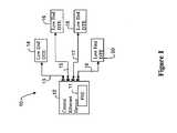
- FIG. 3is a block diagram illustrating the integration of the present invention into a legacy (e.g. IEEE 802.3) Ethernet network.
- a legacye.g. IEEE 802.3
- an Ultra Low Cost Ethernet (UCLE) network 10is shown to include a number of low end Data Terminal Equipment (DTE) devices 14 , 16 , 18 and 20 coupled to an Ethernet device 12 , which may be a Switch, Hub/Repeater or any other type of device capable of transmitting an Ethernet signal. Connection between the Ethernet device 12 and DTEs 14 , 16 , 18 and 20 is provided via respective communication links 13 , 15 , 17 and 19 .
- each of the communication links 13 , 15 , 17 and 19consists of a single pair of conductors.
- the single pair of conductorsare twisted pair cable; a type of cable that consists of two independently insulated copper wires twisted around one another.
- the Ethernet device 12includes power sourcing equipment (PSE) 11 which provides AC current to the pair of conductors for the purposes of powering the attached DTE via its included AC/DC converter.
- PSEpower sourcing equipment
- the present invention's use of a single twisted pair communication link for Ethernet communicationdiffers significantly from existing Ethernet networks, which generally use Cat 3 or Cat 5 cable. Both Cat 3 and Cat 5 cable include four sets of twisted pair conductors. Such cabling aids Ethernet systems seeking to achieve 100 M/bit performance, however, much of the cable capacity can be unused in lower performance applications.
- current standardized implementations of Ethernetuse an 8 pin modular connector (IEC 60603-7) This connector is not particularly well suited for automatic termination to controlled impedance cable, because of near-end cross-talk (“NEXT”). NEXT problems arise because of the standardized pin to pair assignments (1-2,3-6, 4-5,7-8).
- a new connector including only two pins (for each pin of the communication link)would be provided for insertion in a wall jack or the like coupled to the Ethernet transceiver.
- the twisted pair communication linkis capable of 10 Mb/s operation; the well established minimum operating speed that is considered to be “real Ethernet”.
- the size and complexity of hardware necessary to support this rate of operationmade it unfeasible to incorporate Ethernet functionality in low cost devices.
- the number of transistors that fit on a chiphas continued to approximately double on a yearly basis.
- the size and cost of the silicon needed to support Ethernet communicationhas decreased to a point that makes it feasible to attach low cost, low end devices to the Ethernet.
- a ‘low end’ devicemay be any device that one may want to remotely control in a residence or commercial space.
- Such low end devicesinclude light switches, thermostats, remote control repeaters, audio/video equipment controls, low duty cycle actuators, simple wired sensors and indicators and other such devices.
- the network 10 of the present inventionmay be provided within the residence or commercial space for the purposes of controlling any low end device in the space. The provision of power as well as data to the individual DTEs reduces the overall wiring that need be provided within the structure.
- Ethernet device 12may be either full-duplex, in one embodiment or half-duplex in an alternate embodiment using Carrier Sense Multiple Access with Collision Detection (CSMA/CD).
- Half-duplex communicationmay be preferable if it is desirable to minimize the transistor count of the attachment devices.
- FIG. 2a block diagram of exemplary components that may be included in an Ethernet transceiver portion of Ethernet transmission device 12 and the DTE are shown. It should be noted that the block diagram is provided for illustrative purposes only, and other devices capable of providing the functionality described below may be substituted herein.
- the isolation transformers 26 and 36are single coil transformers.
- One of the most attractive features (from a safety standpoint) of twisted pair Ethernethas been the galvanic isolation that is provided by the isolation transformer ( 26 , 36 ) at each end of every twisted pair Ethernet Link Segment.
- this featurehas been one that has been more highly resistant to cost reduction over the years than other aspects of Ethernet implementation technology.
- the present inventionreduces the cabling requirement to a single pair, the complexity of isolation is concomitantly reduced, potentially by as much as 50%. In addition to cost reduction, this also reduces the amount of circuit board space required for each port in a hub or switch.
- IEEE Std 802.3afprovided the capability to include power in the data connection, it did not effectively minimize cost of such a connection.
- the cost of providing poweris minimized by distributing a single power supply across the transceiver/DTE pair.
- One advantage of using AC to transmit the poweris that it permits each half of the power supply to be coupled to the equipment side of the transformer at its end, thus maintaining the full isolation feature of 10BASE-T.
- the DC/AC convertermay include transistors to convert the DC signal from the power supply to a square wave AC, which is run though transformer 26 .
- a high frequency AC signalis generated, which increases the efficiency and reduces the size of the transformer.
- the AC/DC converter 32rectifies the new voltage of AC from the output side of the transformer 35 .
- the received voltageis used to power the processing logic of the DTE.
- the maximum power delivered to a DTEis relatively low, for example in the 1 to 2 watt level. Such a power level is sufficient to power many low end devices. It should be noted, however, that the present invention is not limited to the delivery of any specific power level and may be easily adapted by one of skill in the art to provide the appropriate power level for any desired device with low computational requirements.
- One advantage of providing a lower poweris that it lessens any safety and/or regulatory concerns and reduces the withstand energy requirements of the front end of the chip.
- the end device packaging for a DTE that is used in the present inventionis expected to fit easily in a plastic outlet box that will be sized to match the traditional NEMA duplex or simplex outlet enclosure (or its metric equivalent).
- the enclosurehas the traditional switch “look and feel”, although this is expected to evolve to greater functionality in the same size enclosure.
- FIG. 3one method by which an Ultra Low Cost Ethernet network 51 may be incorporated into an existing Ethernet network 52 is shown.
- a low cost interface device 50is provided between ULCE 51 and a legacy based core network 52 .
- This interface deviceis capable of providing 10/100 connection to the core and a 2 port non-filtering bridge to a 10 Mb/s repeater 53 that provides the ULCE connectivity via punch-downs directly mounted on a motherboard.
- ULCE compatible devicesmay be controlled using legacy Ethernet devices.
- a low cost mechanismthat may be used to extend Ethernet capability to low end devices has been shown and described.
- the low cost mechanismprovides sufficient capacity to support Ethernet communications using only a single twisted pair medium. Because only a single twisted pair is used, the overall cost, complexity and size associated with the integrated Ethernet functionality is reduced.
- a distributed power systemdelivers power to a Data Terminal Equipment (DTE) device over the single twisted pair medium. With such an arrangement, Ethernet capability and power may be simultaneously delivered to low end devices at a reduced cost.
- DTEData Terminal Equipment
Landscapes
- Engineering & Computer Science (AREA)
- Computer Networks & Wireless Communication (AREA)
- Signal Processing (AREA)
- Small-Scale Networks (AREA)
Abstract
Description
Claims (2)
Priority Applications (1)
| Application Number | Priority Date | Filing Date | Title |
|---|---|---|---|
| US10/891,172US8223792B2 (en) | 2003-07-14 | 2004-07-14 | Ultra low cost ethernet architecture |
Applications Claiming Priority (2)
| Application Number | Priority Date | Filing Date | Title |
|---|---|---|---|
| US48699903P | 2003-07-14 | 2003-07-14 | |
| US10/891,172US8223792B2 (en) | 2003-07-14 | 2004-07-14 | Ultra low cost ethernet architecture |
Publications (2)
| Publication Number | Publication Date |
|---|---|
| US20050078700A1 US20050078700A1 (en) | 2005-04-14 |
| US8223792B2true US8223792B2 (en) | 2012-07-17 |
Family
ID=34425801
Family Applications (1)
| Application Number | Title | Priority Date | Filing Date |
|---|---|---|---|
| US10/891,172Expired - Fee RelatedUS8223792B2 (en) | 2003-07-14 | 2004-07-14 | Ultra low cost ethernet architecture |
Country Status (1)
| Country | Link |
|---|---|
| US (1) | US8223792B2 (en) |
Cited By (2)
| Publication number | Priority date | Publication date | Assignee | Title |
|---|---|---|---|---|
| US20120263184A1 (en)* | 2011-04-12 | 2012-10-18 | Chien-Chung Lee | Baseband ethernet extender |
| US20160156569A1 (en)* | 2014-11-28 | 2016-06-02 | Igor, Inc. | Node and Method of Assigning Node to Space |
Families Citing this family (27)
| Publication number | Priority date | Publication date | Assignee | Title |
|---|---|---|---|---|
| US6480510B1 (en)* | 1998-07-28 | 2002-11-12 | Serconet Ltd. | Local area network of serial intelligent cells |
| US6956826B1 (en)* | 1999-07-07 | 2005-10-18 | Serconet Ltd. | Local area network for distributing data communication, sensing and control signals |
| US6549616B1 (en) | 2000-03-20 | 2003-04-15 | Serconet Ltd. | Telephone outlet for implementing a local area network over telephone lines and a local area network using such outlets |
| US6961303B1 (en) | 2000-09-21 | 2005-11-01 | Serconet Ltd. | Telephone communication system and method over local area network wiring |
| IL152824A (en) | 2002-11-13 | 2012-05-31 | Mosaid Technologies Inc | Addressable outlet and a network using same |
| IL154234A (en) | 2003-01-30 | 2010-12-30 | Mosaid Technologies Inc | Method and system for providing dc power on local telephone lines |
| IL159838A0 (en) | 2004-01-13 | 2004-06-20 | Yehuda Binder | Information device |
| CN101099397B (en)* | 2004-05-03 | 2012-02-08 | 泛达公司 | Powered patch panel |
| US7500118B2 (en)* | 2005-03-28 | 2009-03-03 | Akros Silicon Inc. | Network device with power potential rectifier |
| WO2006114687A2 (en) | 2005-04-26 | 2006-11-02 | Accedian Networks Inc. | Power over ethernet management devices and connection between ethernet devices |
| US7978845B2 (en) | 2005-09-28 | 2011-07-12 | Panduit Corp. | Powered patch panel |
| US20070171690A1 (en)* | 2006-01-26 | 2007-07-26 | Silicon Laboratories, Inc. | Active diode bridge system and method |
| US20070170903A1 (en)* | 2006-01-26 | 2007-07-26 | Silicon Laboratories, Inc. | Active diode bridge system |
| US8693496B2 (en)* | 2006-01-27 | 2014-04-08 | Texas Instruments Incorporated | Diode bridge configurations for increasing current in a distributed power network |
| EP2093941B1 (en) | 2008-02-22 | 2010-08-25 | FESTO AG & Co. KG | Field bus system |
| FR2954025B1 (en)* | 2009-12-16 | 2012-01-06 | Sagem Defense Securite | CONNECTION DEVICE VIA AN ETHERNET CONNECTION OF TWO EQUIPMENTS AND STATION FOR RECEIVING ONE OF THESE EQUIPMENTS |
| FR2987201B1 (en)* | 2012-02-16 | 2017-12-01 | Thales Sa | INFORMATION TRANSMISSION NETWORK AND TRANSMISSION RING NODE |
| US10999171B2 (en) | 2018-08-13 | 2021-05-04 | Accedian Networks Inc. | Method for devices in a network to participate in an end-to-end measurement of latency |
| US8830860B2 (en) | 2012-07-05 | 2014-09-09 | Accedian Networks Inc. | Method for devices in a network to participate in an end-to-end measurement of latency |
| US12192084B2 (en) | 2012-07-05 | 2025-01-07 | Accedian Networks Inc. | Method for devices in a network to participate in an end-to-end measurement of latency |
| CN104919783B (en) | 2012-12-05 | 2019-01-25 | 西门子加拿大有限公司 | Network equipment mounting rails for attaching removable modules |
| US10411504B2 (en) | 2013-07-31 | 2019-09-10 | Texas Instruments Incorporated | System and method for controlling power delivered to a powered device through a communication cable |
| US9294355B2 (en) | 2013-12-16 | 2016-03-22 | Cisco Technology, Inc. | Adjustable data rates |
| US20160064939A1 (en)* | 2014-08-27 | 2016-03-03 | In Win Development, Inc. | Using power over ethernet protocol to augment a dc/ac power module inverter and application thereof |
| US10979332B2 (en) | 2014-09-25 | 2021-04-13 | Accedian Networks Inc. | System and method to measure available bandwidth in ethernet transmission system using train of ethernet frames |
| US10146236B2 (en)* | 2015-01-09 | 2018-12-04 | Lennox Industries Inc. | Two conductor wireline guided control and an HVAC system employing the same |
| US10389539B2 (en) | 2015-08-07 | 2019-08-20 | Texas Instruments Incorporated | Turn on method without power interruption redundant power over Ethernet systems |
Citations (11)
| Publication number | Priority date | Publication date | Assignee | Title |
|---|---|---|---|---|
| US5994998A (en)* | 1997-05-29 | 1999-11-30 | 3Com Corporation | Power transfer apparatus for concurrently transmitting data and power over data wires |
| US6018447A (en)* | 1997-11-21 | 2000-01-25 | Intel Corporation | Method and apparatus for reducing ground fault risks in cabled signal lines |
| US6448899B1 (en)* | 2000-10-25 | 2002-09-10 | Nortel Networks Limited | Power indicating ethernet outlet and method therefor |
| US6470053B1 (en)* | 1998-10-30 | 2002-10-22 | Compaq Information Technologies Group, L.P. | Methods and arrangements for transmitting data over twisted pair wire using RF modulation techniques |
| US6535983B1 (en)* | 1999-11-08 | 2003-03-18 | 3Com Corporation | System and method for signaling and detecting request for power over ethernet |
| US20040105467A1 (en)* | 2002-09-12 | 2004-06-03 | Inline Connection Corporation | System and method for 10baset ethernet communication over a single twisted pair utilizing internal power sources |
| US20040239512A1 (en)* | 2003-05-30 | 2004-12-02 | Adc Dsl Systems, Inc. | Lightning protection for a network element |
| US20060056444A1 (en)* | 1998-07-28 | 2006-03-16 | Serconet, Ltd | Local area network of serial intelligent cells |
| US7046983B2 (en)* | 1999-08-02 | 2006-05-16 | Powerdsine, Ltd. | Integral board and module for power over LAN |
| US7453895B2 (en)* | 2001-10-11 | 2008-11-18 | Serconet Ltd | Outlet with analog signal adapter, a method for use thereof and a network using said outlet |
| US7715534B2 (en)* | 2000-03-20 | 2010-05-11 | Mosaid Technologies Incorporated | Telephone outlet for implementing a local area network over telephone lines and a local area network using such outlets |
- 2004
- 2004-07-14USUS10/891,172patent/US8223792B2/ennot_activeExpired - Fee Related
Patent Citations (11)
| Publication number | Priority date | Publication date | Assignee | Title |
|---|---|---|---|---|
| US5994998A (en)* | 1997-05-29 | 1999-11-30 | 3Com Corporation | Power transfer apparatus for concurrently transmitting data and power over data wires |
| US6018447A (en)* | 1997-11-21 | 2000-01-25 | Intel Corporation | Method and apparatus for reducing ground fault risks in cabled signal lines |
| US20060056444A1 (en)* | 1998-07-28 | 2006-03-16 | Serconet, Ltd | Local area network of serial intelligent cells |
| US6470053B1 (en)* | 1998-10-30 | 2002-10-22 | Compaq Information Technologies Group, L.P. | Methods and arrangements for transmitting data over twisted pair wire using RF modulation techniques |
| US7046983B2 (en)* | 1999-08-02 | 2006-05-16 | Powerdsine, Ltd. | Integral board and module for power over LAN |
| US6535983B1 (en)* | 1999-11-08 | 2003-03-18 | 3Com Corporation | System and method for signaling and detecting request for power over ethernet |
| US7715534B2 (en)* | 2000-03-20 | 2010-05-11 | Mosaid Technologies Incorporated | Telephone outlet for implementing a local area network over telephone lines and a local area network using such outlets |
| US6448899B1 (en)* | 2000-10-25 | 2002-09-10 | Nortel Networks Limited | Power indicating ethernet outlet and method therefor |
| US7453895B2 (en)* | 2001-10-11 | 2008-11-18 | Serconet Ltd | Outlet with analog signal adapter, a method for use thereof and a network using said outlet |
| US20040105467A1 (en)* | 2002-09-12 | 2004-06-03 | Inline Connection Corporation | System and method for 10baset ethernet communication over a single twisted pair utilizing internal power sources |
| US20040239512A1 (en)* | 2003-05-30 | 2004-12-02 | Adc Dsl Systems, Inc. | Lightning protection for a network element |
Cited By (2)
| Publication number | Priority date | Publication date | Assignee | Title |
|---|---|---|---|---|
| US20120263184A1 (en)* | 2011-04-12 | 2012-10-18 | Chien-Chung Lee | Baseband ethernet extender |
| US20160156569A1 (en)* | 2014-11-28 | 2016-06-02 | Igor, Inc. | Node and Method of Assigning Node to Space |
Also Published As
| Publication number | Publication date |
|---|---|
| US20050078700A1 (en) | 2005-04-14 |
Similar Documents
| Publication | Publication Date | Title |
|---|---|---|
| US8223792B2 (en) | Ultra low cost ethernet architecture | |
| US8279883B2 (en) | High speed isolation interface for PoE | |
| US8885659B2 (en) | Local area network of serial intelligent cells | |
| CN1871750B (en) | modular socket | |
| US6640308B1 (en) | System and method of powering and communicating field ethernet device for an instrumentation and control using a single pair of powered ethernet wire | |
| US8261001B2 (en) | Network range extender device | |
| CN212183141U (en) | Power line networking type USB power adapter for Internet of things | |
| US20020041228A1 (en) | Apparatus for power line computer network system | |
| US10812137B2 (en) | Switch for use with single pair ethernet on four-pair cabling | |
| US9036653B2 (en) | PoE communication bus, interface, and protocol between PoE subsystem and PHY or switch subsystems | |
| US20070288771A1 (en) | Source Separator for Power over Ethernet Systems | |
| US20070147354A1 (en) | Local area network | |
| US20100049994A1 (en) | Universal Ethernet Power Adapter | |
| US9606615B2 (en) | Apparatus, method and computer program means for data transport with reduced power consumption during link idle times | |
| CN103152183A (en) | Electric modem switching device and method for mutual switching of electric signals and network signals | |
| WO2007140467A2 (en) | Ethernet module | |
| CN105515927A (en) | Remote serial port communication system and method based on Ethernet Cat.5 wiring framework | |
| AU2013265061B2 (en) | An electrical system adapted to transfer data and power between devices on a network | |
| CN100508461C (en) | Two-wire cable power supply device, power receiving device, system and method | |
| US20070110026A1 (en) | Systems and methods for dual power and data over a single cable | |
| US6992599B2 (en) | Terminal adapter for connecting a terminal to a computer local area network capable of identifying any of several terminal types | |
| CN112600016A (en) | Interface device, power supply apparatus, power receiving apparatus, and power consumption system | |
| KR20080057614A (en) | Integrated telephone and data network with UTIP cable | |
| KR100427741B1 (en) | Ethernet System Capable of Supplying Electric Power by using a UTP Cable | |
| US20240345642A1 (en) | Ethernet media converter apparatuses and systems |
Legal Events
| Date | Code | Title | Description |
|---|---|---|---|
| AS | Assignment | Owner name:NORTEL NETWORKS LIMITED, CANADA Free format text:ASSIGNMENT OF ASSIGNORS INTEREST;ASSIGNOR:THOMPSON, GEOFFREY O.;REEL/FRAME:016220/0103 Effective date:20041018 | |
| AS | Assignment | Owner name:ROCKSTAR BIDCO, LP, NEW YORK Free format text:ASSIGNMENT OF ASSIGNORS INTEREST;ASSIGNOR:NORTEL NETWORKS LIMITED;REEL/FRAME:027143/0717 Effective date:20110729 | |
| AS | Assignment | Owner name:ROCKSTAR CONSORTIUM US LP, TEXAS Free format text:ASSIGNMENT OF ASSIGNORS INTEREST;ASSIGNOR:ROCKSTAR BIDCO, LP;REEL/FRAME:032168/0750 Effective date:20120509 | |
| AS | Assignment | Owner name:BOCKSTAR TECHNOLOGIES LLC, DELAWARE Free format text:ASSIGNMENT OF ASSIGNORS INTEREST;ASSIGNOR:ROCKSTAR CONSORTIUM US LP;REEL/FRAME:032399/0116 Effective date:20131113 | |
| AS | Assignment | Owner name:RPX CLEARINGHOUSE LLC, CALIFORNIA Free format text:ASSIGNMENT OF ASSIGNORS INTEREST;ASSIGNORS:ROCKSTAR CONSORTIUM US LP;ROCKSTAR CONSORTIUM LLC;BOCKSTAR TECHNOLOGIES LLC;AND OTHERS;REEL/FRAME:034924/0779 Effective date:20150128 | |
| REMI | Maintenance fee reminder mailed | ||
| AS | Assignment | Owner name:JPMORGAN CHASE BANK, N.A., AS COLLATERAL AGENT, IL Free format text:SECURITY AGREEMENT;ASSIGNORS:RPX CORPORATION;RPX CLEARINGHOUSE LLC;REEL/FRAME:038041/0001 Effective date:20160226 | |
| LAPS | Lapse for failure to pay maintenance fees | ||
| STCH | Information on status: patent discontinuation | Free format text:PATENT EXPIRED DUE TO NONPAYMENT OF MAINTENANCE FEES UNDER 37 CFR 1.362 | |
| FP | Lapsed due to failure to pay maintenance fee | Effective date:20160717 | |
| AS | Assignment | Owner name:RPX CORPORATION, CALIFORNIA Free format text:RELEASE (REEL 038041 / FRAME 0001);ASSIGNOR:JPMORGAN CHASE BANK, N.A.;REEL/FRAME:044970/0030 Effective date:20171222 Owner name:RPX CLEARINGHOUSE LLC, CALIFORNIA Free format text:RELEASE (REEL 038041 / FRAME 0001);ASSIGNOR:JPMORGAN CHASE BANK, N.A.;REEL/FRAME:044970/0030 Effective date:20171222 |