US8223633B2 - Port trunking at a fabric boundary - Google Patents
Port trunking at a fabric boundaryDownload PDFInfo
- Publication number
- US8223633B2 US8223633B2US12/245,269US24526908AUS8223633B2US 8223633 B2US8223633 B2US 8223633B2US 24526908 AUS24526908 AUS 24526908AUS 8223633 B2US8223633 B2US 8223633B2
- Authority
- US
- United States
- Prior art keywords
- ports
- node device
- port
- edge switch
- trunk
- Prior art date
- Legal status (The legal status is an assumption and is not a legal conclusion. Google has not performed a legal analysis and makes no representation as to the accuracy of the status listed.)
- Active, expires
Links
- 239000004744fabricSubstances0.000titleclaimsabstractdescription132
- 238000004891communicationMethods0.000claimsabstractdescription180
- 238000000034methodMethods0.000claimsdescription35
- 238000013507mappingMethods0.000claimsdescription21
- 239000000835fiberSubstances0.000claimsdescription19
- 239000000284extractSubstances0.000claimsdescription10
- 238000001514detection methodMethods0.000claimsdescription6
- 230000004044responseEffects0.000claimsdescription5
- 238000000605extractionMethods0.000claims8
- 230000005540biological transmissionEffects0.000description9
- 238000012546transferMethods0.000description7
- 230000008569processEffects0.000description4
- 230000008859changeEffects0.000description3
- 238000005516engineering processMethods0.000description3
- 239000003999initiatorSubstances0.000description3
- 238000013500data storageMethods0.000description2
- 238000007726management methodMethods0.000description2
- 230000006855networkingEffects0.000description2
- 230000011664signalingEffects0.000description2
- 238000013316zoningMethods0.000description2
- 208000033748Device issuesDiseases0.000description1
- 230000001419dependent effectEffects0.000description1
- 230000000694effectsEffects0.000description1
- 230000006870functionEffects0.000description1
- 238000002955isolationMethods0.000description1
- 238000012545processingMethods0.000description1
- 229920000638styrene acrylonitrilePolymers0.000description1
Images


Classifications
- H—ELECTRICITY
- H04—ELECTRIC COMMUNICATION TECHNIQUE
- H04L—TRANSMISSION OF DIGITAL INFORMATION, e.g. TELEGRAPHIC COMMUNICATION
- H04L67/00—Network arrangements or protocols for supporting network services or applications
- H04L67/01—Protocols
- H04L67/10—Protocols in which an application is distributed across nodes in the network
- H04L67/1097—Protocols in which an application is distributed across nodes in the network for distributed storage of data in networks, e.g. transport arrangements for network file system [NFS], storage area networks [SAN] or network attached storage [NAS]
- H—ELECTRICITY
- H04—ELECTRIC COMMUNICATION TECHNIQUE
- H04L—TRANSMISSION OF DIGITAL INFORMATION, e.g. TELEGRAPHIC COMMUNICATION
- H04L45/00—Routing or path finding of packets in data switching networks
- H04L45/24—Multipath
- H04L45/245—Link aggregation, e.g. trunking
- Y—GENERAL TAGGING OF NEW TECHNOLOGICAL DEVELOPMENTS; GENERAL TAGGING OF CROSS-SECTIONAL TECHNOLOGIES SPANNING OVER SEVERAL SECTIONS OF THE IPC; TECHNICAL SUBJECTS COVERED BY FORMER USPC CROSS-REFERENCE ART COLLECTIONS [XRACs] AND DIGESTS
- Y02—TECHNOLOGIES OR APPLICATIONS FOR MITIGATION OR ADAPTATION AGAINST CLIMATE CHANGE
- Y02D—CLIMATE CHANGE MITIGATION TECHNOLOGIES IN INFORMATION AND COMMUNICATION TECHNOLOGIES [ICT], I.E. INFORMATION AND COMMUNICATION TECHNOLOGIES AIMING AT THE REDUCTION OF THEIR OWN ENERGY USE
- Y02D30/00—Reducing energy consumption in communication networks
- Y02D30/50—Reducing energy consumption in communication networks in wire-line communication networks, e.g. low power modes or reduced link rate
Definitions
- a storage area networkmay be implemented as a high-speed, special purpose network that interconnects different kinds of data storage devices with associated data servers on behalf of a large network of users.
- a SANincludes high performance switches as part of the overall network of computing resources for an enterprise.
- the storage area networkis usually clustered in close geographical proximity to other computing resources, such as mainframe computers, but may also extend to remote locations for backup and archival storage using wide area network carrier technologies.
- Fibre Channel networkingis typically used in SANs although other communication technologies may also be employed, including Ethernet and IP-based storage networking standards (e.g., iSCSI, FCIP (Fibre Channel over IP), etc.).
- Fibre Channelrefers to the Fibre Channel (FC) family of standards (developed by the American National Standards Institute (ANSI)) and other related and draft standards.
- Fibre Channeldefines a transmission medium based on a high speed communications interface for the transfer of large amounts of data via connections between varieties of hardware devices.
- one or more Fibre Channel switchesare used to communicatively connect one or more server devices with one or more data storage devices.
- Such switchesgenerally support a high performance switching fabric and provide a number of communication ports for connecting via individual communication links with other switches, host servers, storage devices, or other SAN devices.
- a communication link between one of the devices and the switching fabricbecomes disabled (e.g., someone unplugs a link between a host and an edge switch of the switching fabric)
- the process of re-establishing communications for that devicee.g., for the host
- re-establishing communicationscan alter the identity by which the device is known by other fabric-connected devices.
- loss of a communications linkcan create bottlenecks in other communications links connecting the device to the fabric.
- Implementations described and claimed hereinaddress the foregoing problems by logically trunking F_PORTs of an edge switch of a fabric and N_PORTs of a node device outside the fabric via a trunked group of communications links.
- node devicesmay include without limitation host bus adapters (HBAs), including multi-port HBAs, and virtualization devices.
- HBAshost bus adapters
- the trunked N_PORTs of the node deviceare configured to send frames of a particular stream across the multiple trunked links to arrive in-order at the trunked F_PORTs of the edge switch.
- the trunked F_PORTs of the edge switchare configured to send frames of a particular stream across the multiple trunked links to arrive in-order at the trunked N_PORTs of the node device.
- Such a trunking configuration between N_PORTs and F_PORTsincreases the effective communications speed between node devices and the fabric. Furthermore, such trunking also increases the link utilization between the node devices and the edge switch, in that multiple end nodes may be communicating over multiple, shared trunked links.
- the node device outside the fabricinitially negotiates with the edge switch using a sequence of fabric login requests and fabric login acceptances to establish the trunked connection between the devices (and their respective ports).
- the edge switchalso identifies a destination port identifier of a master F_PORT of the edge switch, which is logically shared by all of the trunked F_PORTs.
- This destination port identifierspecifies a single Area for all of the trunked F_PORTs.
- all frames arriving at the edge switch from the fabricare routed internally to a transmit queue dedicated to the trunk.
- Individual F_PORTs of the trunk groupthen extract front the dedicated transmit queue and transmit these frames to the node device on an in-order basis from the transmit queue of the trunk.
- the node deviceestablishes a destination port identifier for one of its N_PORTs, called a master N_PORT. All F_PORTs of the node device are internally mapped to the master N_PORT. Furthermore, frames arriving at the node device from an end node (e.g., a storage device, host, or virtual machine) and destined for the trunk are routed internally to the transmit queuededicate to the trunk. Individual N_PORTs of the trunk group then extract from the dedicated transmit queue and transmit these frames to the edge switch on an in-order basis from the transmit queue of the trunk.
- an end nodee.g., a storage device, host, or virtual machine
- loss of one communication link/port in a trunked group between the node device and the edge switchdoes not require the connected host, storage device, or virtual machine (all of which may be termed an “end node”) to re-login to the fabric. Instead, data communications continue through the other still-enabled communications links/ports within the trunk using the same destination port identifier of the master trunk port.
- the node deviceFor example, if communications through the current master N_PORT of the node device are disabled, then the node device merely changes its internal mapping of its F_PORTs to a new master N_PORT in the trunk. However, frames continue to be forwarded to the same transmit queue associated with the trunk. If communications through the master N_PORT or a non-master (“slave”) N_PORT of the node device is disabled, then that disabled N_PORT's transmit logic merely stops extracting frames from the transmit queue of the trunk in the node device and drops out of the communications, while the other trunked N_PORTs in the node device continue with their communications.
- the initiator end nodes connected to the F_PORTs of the node devicestill send their frames to the same F_PORT identifier, which specifies the Area attributed to the trunked F_PORTs on the edge switch. In this manner, the initiator end nodes are not required to log out and then re-log into the fabric. As such, the communications of the trunked group remains in intact, albeit without the bandwidth previously provided by the disabled communications link/ports.
- all of the F_PORTs in the edge switchare assigned the same port identifier, and more specifically, the same Area.
- the edge switchmerely designates a new master F_PORT.
- the internal Area routing of the edge switchneed not change—frames can still be forwarded internally to the transmit queue of the trunk in the edge switch and the transmit logic of the still-active transmit F_PORTs in the edge switch continues to extract and allocate the frames among the still-active F_PORTs from the transmit queue of the trunk, in the absence of the disabled F_PORT.
- the communications of the trunked groupremains in intact, albeit without the bandwidth previously provided by the disabled communications link/ports.
- the transmit queue logic of both the edge switch and the node devicetransmit frames in such a way that the frames across the multiple trunked links are received in-order at the other device, despite any skew introduced by differences in transmission times across the individual communication links.
- FIG. 1illustrates an exemplary computing and storage framework including a storage area network (SAN).
- SANstorage area network
- FIG. 2illustrates additional details of a node device and an edge switch interconnected via trunked communication links.
- FIG. 3illustrates example port mappings between a node device and an edge switch interconnected via trunked communication links.
- FIG. 4illustrates example port mappings between a node device and an edge switch interconnected via trunked communication links after disablement of a slave N_PORT in a trunk.
- FIG. 5illustrates example port mappings between a node device and an edge switch interconnected via trunked communication links after disablement of a master N_PORT in a trunk.
- FIG. 6illustrates example port mappings between a node device and an edge switch interconnected via trunked communication links, in the opposite direction as described with regard to FIG. 3 .
- FIG. 7illustrates example port mappings between a node device and an edge switch interconnected via trunked communication links after disablement of a slave F_PORT in a trunk, in the opposite direction as described with regard to FIG. 4 .
- FIG. 8illustrates example port mappings between a node device and an edge switch interconnected via trunked communication links after disablement of a master trunk F_PORT in a trunk, in the opposite direction as described with regard to FIG. 5 .
- FIG. 9illustrates example communications/operations between a node device and an edge switch for initializing F_PORT trunking.
- FIG. 1illustrates an exemplary computing and storage framework including a storage area network (SAN).
- Switches 102 , 104 , 106 , and 108form a switching fabric 110 .
- the switches 102 and 104operate as edge switches at the edge of the switching fabric 110 and are operatively connected to a node device 112 , which is in turn operatively connected to hosts 114 .
- the switches 106 and 108also operate as edge switches at the edge of the switching fabric 110 and are operatively connected to storage devices 116 .
- the storage devices 116 and the hosts 114are generally termed “end nodes” and are connected to a fabric via HBAs and/or virtualization devices.
- HBAs and virtualization devicesare generally termed “node devices” because they present an N_PORT for connection to an F_PORT. It should also be understood that the switching fabric 110 may also include additional switches interconnecting among the switches 102 , 104 , 106 , and 108 in various configurations.
- Each switch, storage device, and host, as well as the node device 112provides multiple communication ports. Each port operates in accordance with a specified signaling protocol, depending on its purpose and connectivity.
- the ports connecting a communication link between two switchesare termed “E_PORTs”, and the communication link is termed an “Inter Switch Link” (ISL).
- ISLInter Switch Link
- Each port of a switch connecting a communication link across a fabric boundary between the switch and a node device outside the fabric 110e.g., a storage device 116 , a node device 112 , a host 114 , etc.
- F_PORTEach port of a node connecting a communication link across a fabric boundary between the node and a switch
- N_PORTEach port of a node connecting a communication link across a fabric boundary between the node and a switch.
- N_PORTIn this configuration, an F_PORT of a switch in the fabric 110 connects to an N_PORT of a node device outside the fabric 110 .
- N_PORT, F_PORT, and E_PORTidentify a type of port employed in relation to a Fibre Channel network.
- ports complying with the signaling protocol of N_PORTs and F_PORTsmay also be implemented outside of the fabric boundary and such ports are also termed N_PORTs and F_PORTs, respectively, as described below with regard to the node device 112 .
- the edge switch 102can present F_PORTs or FL_PORTs to the hosts 114 and present E_PORTs, TE_PORTs, or EX_PORTs to other switches in the fabric 110 .
- the edge switch 102consumes fabric resources, such as domain IDs, and participates in the fabric management and zoning distribution.
- fabric resourcessuch as domain IDs
- the node device 112is acting as a virtualization device and generally does not consume fabric resources or participate in fabric management and zoning distribution.
- the node device 112presents F_PORTs to the N_PORTs of the HBAs of hosts 114 and N_PORTs to the F_PORTs of the edge switch 102 .
- each of the connections between the node device 112 and the edge switch 102consist of multiple trunked communication links (e.g., Fibre Channel cables). That is, each connection 118 and 120 includes multiple communication links that are configured as a trunk, which allows the node device 112 and edge switch 102 to distribute traffic load among the communication links of each trunk. In this manner, the traffic load received at the trunked transmit ports of each device are routed for distribution across the corresponding trunk. By doing so, the traffic load may be distributed over the links of the trunked group in an evenly distributed or load-balancing manner. Moreover, the trunk ensures in-order delivery of frames in an ordered stream to the device at the other end of the trunk.
- trunkensures in-order delivery of frames in an ordered stream to the device at the other end of the trunk.
- the node device 112allows multiple hosts (or host bus adapters or HBAs) to access the fabric 110 using fewer physical F_PORTs within the fabric 110 than would be achievable without virtualization.
- the node device 112is logically transparent to the connected hosts 114 and the fabric 110 , multiplexing host connections to the fabric 110 without the hosts or the fabric making any special configuration changes.
- the node device 112uses an FC facility called N_PORT ID virtualization (NPIV) that allows multiple N_PORT IDs to share a single N_PORT (e.g., on the node device 112 ).
- NPIVN_PORT ID virtualization
- multiple FC initiator nodese.g., the hosts 114
- N_PORTor group of trunked N_PORTs
- F_PORTor group of trunked F_PORTs
- edge switchsuch as edge switch 102
- More details regarding example virtualization techniquesmay be found in U.S. Patent Publication No. 2005/019523A1, entitled ISOLATION SWITCH FOR FIBRE CHANNEL FABRICS IN STORAGE AREA NETWORKS, U.S. patent application Ser. No. 10/767,405, filed Jan. 29, 2005, which is specifically incorporated by reference for all that it discloses and teaches.
- HBAhost bus adapter
- Virtualization in an HBAmay be employed, for example, to support multiple virtual machines running different operating systems on a single host. Other uses of virtualization may also be applied.
- a multiport HBAmay also be used to provide increased effective communications speed, link efficiency, and redundancy between an end node and a fabric, independent of any virtualization.
- a storage devicemay be equipped with a multi-port HBA to connect to an edge switch in a fabric via multiple communications links.
- the multi-port HBAcan transmit and receive frames of a single communications stream over the multiple communications link via a trunk on an in-order basis.
- the storage devicebenefits from improved communication speed from the aggregated bandwidth of the multiple links, improved link efficiency, and improved redundancy.
- the storage deviceneed not re-login to the fabric if a communications link is disabled during communications, the communications are not interrupted.
- each N_PORT of the node device 112sends an FLOGI to the edge switch 102 to log the host 114 into the fabric 110 and obtain a valid N_PORT ID, provided via an FLOGI ACC response from the edge switch 102 . Then, each N_PORT sends a PLOGI to the edge switch 102 to register the valid N_PORT ID with a name server of the fabric 110 .
- the PLOGIidentifies the master N_PORT and the node device's F_PORT that is connected to the originating end node.
- the PLOGIidentifies the master N_PORT and the F_PORT associated with the originating virtual machine.
- a N_PORT of the node device 112such as a master N_PORT of a trunk, also sends an FDISC to obtain an additional N_PORT ID, another PLOGI to register the additional N_PORT ID with the name server.
- the edge switch 102can uniquely address the single physical N_PORT (or group of trunked N_PORTs) with frames destined for the multiple hosts 114 .
- the node device 112may embody a multi-port HBA that, independent of virtualization, provides trunking capabilities for a connected end node (e.g., the multi-port HBA connects to a storage device via an internal bus).
- the PLOGIidentifies the master N_PORT of trunk on the HBA. Frames from the storage device are routed to the transmit queue of the trunk for transmission to the fabric.
- the edge switch 102can uniquely address the master N_PORT (or group of trunked N_PORTs) with frames destined for the storage device.
- the node device 112when the node device 112 connects to the edge switch 102 , the node device 112 logs its hosts and their N_PORTs into the fabric 110 . In addition, a set of transmit ports (and therefore the corresponding connected communication links) are designated as being “trunked”. Accordingly, for frames destined for the trunk group, the node device 112 sets up its mapping tables and transmit (TX) queuing logic to internally map F_PORTs in accordance with an identifier of a designated master N_PORT in the trunk of the node device 112 . Furthermore, the frames received at the F_PORTs are forwarded to a transmit queue associated with the trunked N_PORTs. The TX queuing logic for all trunked N_PORTs in the trunked group then uses the transmit queue of the trunk to extract frames for transmission, thereby allowing each N_PORT in the trunked group to send frames from the transmit queue associated with the trunk.
- TXtransmit
- the edge switch 102sets up its routing tables and transmit (TX) queuing logic to cause the set of trunked F_PORTs to use only the transmit queue associated with the trunked transmit F_PORTs.
- TXtransmit
- the routing table entries of all other trunked F_PORTs in the deviceare set up to forward frames destined for the trunked group to the transmit queue of the trunk.
- the TX queuing logic for all F_PORTs in the trunked groupthen uses only the transmit queue of the trunk to extract frames for transmission, thereby allowing each F_PORT in the trunked group to send frames from the transmit queue of the trunk.
- the TX queuing logic modules of the trunked transmit portsoperate to ensure in-order delivery of transmitted frames to the edge switch 102 . Furthermore, when the frames are received at the destination device (e.g., the edge switch 102 or the node device 112 ), the frames are collected in-order in the receive queue of the destination device's trunk and forwarded to an appropriate egress port of the device for transmission to a destination end node, whether through the fabric 110 or not.
- the destination devicee.g., the edge switch 102 or the node device 112
- the framesare collected in-order in the receive queue of the destination device's trunk and forwarded to an appropriate egress port of the device for transmission to a destination end node, whether through the fabric 110 or not.
- FIG. 2illustrates additional details of a node device 200 and an edge switch 202 interconnected via trunked communication links 204 .
- the node device 200includes a central processing unit (CPU) module 206 that controls the initialization of the node device 200 , although various configurations may be employed.
- the CPU module 206typically includes a processor used with a local memory module 208 .
- Additional components 210can also be included in the node device 200 , such as transmit and receive queues 212 , a clock timer 214 , additional memory, registers, logical routing tables, etc.
- the additional componentsare shown as embodied within an Application Specific Integrated Circuit (ASIC) 216 in the node device 200 , although other implementations may be employed.
- ASICApplication Specific Integrated Circuit
- the node device 200presents F_PORTs 230 for connection to one or more end nodes (not shown). Frames may be received from such nodes through the F_PORTs 230 of the node device 200 and forwarded through the trunked N_PORTs 232 of the node device 200 and the trunked communications links 204 to the edge switch 202 .
- the F_PORTs 230 of the node device 200map to the master N_PORT identifier of the node device 200 in accordance with a mapping table. Furthermore, the frames received at the F_PORTs 230 are forwarded to a transmit queue associated with the trunk and are then distributed among the trunked N_PORTs 232 for transmission to the edge switch 202 .
- frame traffichas been described in one direction through the node device 200 , it should be understood that frame traffic may flow bidirectionally through the node device 200 . Accordingly, frames received from the edge switch 202 at the trunked N_PORTs 232 are collected in an in-order manner in a receive queue of the trunk and forwarded to the appropriate F_PORT of the node device 200 for transmission to the appropriate end node.
- the edge switch 202has a similar configuration as compared to the node device 200 , although the two devices may differ in various ways according to their functions.
- the edge switch 202includes a CPU module 218 that controls the initialization of the edge switch 202 .
- the CPU module 218typically includes a processor used with a local memory module 220 .
- additional components 222can also be included in the edge switch 202 , such as transmit and receive queues 224 , a clock timer 226 , additional memory, registers, logical routing tables, etc.
- the additional componentsare shown as embodied within an ASIC 228 in the edge switch 202 , although other implementations may be employed.
- the trunked communications links 204are connected between N_PORTs 232 of the node device 200 and the F_PORTs 234 of the edge switch 202 . Frames may be received from the trunked N_PORTs 232 of the node device 200 across the trunked communication links 204 by the trunked F_PORTs 234 of the edge switch 202 and forwarded through the edge switch 202 through E_PORTs 236 to other switches in the fabric.
- frame traffichas been described in one direction through the edge switch 202 , it should be understood that frame traffic may flow bidirectionally through the edge switch 202 . Accordingly, frames received at the E_PORTs 236 route to the trunk queue of the edge switch 202 in accordance with an Area routing table and are then distributed among the trunked F_PORTs 234 for transmission to the trunked N_PORTs 232 of the node device 200 .
- the set of communications links 204are combined into a trunk group by way of a firmware-driven process.
- the trunked communications links 204are coupled to each device by ports 230 and 232 .
- the node device 200 and edge switch 202then set up their respective mapping/routing tables to identify the port identifier of the master port (e.g., master N_PORT or master F_PORT) and to set up their transmit (TX) queuing logic (e.g., queues 212 and 224 ) to cause the set of trunked ports of each device to use the transmit queues associated with the trunked ports in each device.
- the master porte.g., master N_PORT or master F_PORT
- TX queuing logice.g., queues 212 and 224
- mapping/routing table entries of other ports on the node device 200 and the edge switch 202identify a port identifier associated with the trunked group. Furthermore, received frames destined for the trunk are forwarded to a transmit queue associated with the trunk. As such, the TX queuing logic for all ports in the trunked group use the transmit queue of the trunk to determine frame selections (i.e., which frames to send), allowing each port in the trunked group to send any frames from the trunk's transmit queue across any of the communication links in the trunk.
- the TX queuing logic of all trunked ports in the transmitting deviceensures that frames are delivered in-order to the receive ports of the device on the receive-side of the trunked communication links 204 . Absent an effective trunking technology, out-of-order delivery of frames between end-point source and destination ports could occur due to skew between communication links in a trunked group (e.g., the link lengths between each transmit and receiving port pair may differ among links in the trunked communication links 204 ).
- the trunking logic in the TX queuing logicincludes a clock timer 214 that binds a particular queue in the master trunk port to a particular communication link in the trunked group for a time sufficient to ensure “in-order” delivery across multiple communication links.
- a clock timer 214that binds a particular queue in the master trunk port to a particular communication link in the trunked group for a time sufficient to ensure “in-order” delivery across multiple communication links.
- FIG. 3illustrates example port mappings between a node device 300 and an edge switch 302 interconnected via trunked communication links 310 .
- Hosts 318i.e., example end nodes
- F_PORTs 304are connected to F_PORTs 304 of the node device 300 .
- a mapping table of the node device 300maps each of the F_PORTs to the master N_PORT 306 of the trunked group in the node device 300 , and the incoming frames from the hosts 318 are forwarded to a transmit queue associated with the trunked group.
- the transmit logic of the master N_PORT 306 and the slave N_PORTs 308extracts the frames from the transmit queue of the trunk and transmits these frames in-order through the trunked communications links 310 .
- a disabled link(e.g., a disconnected or cut cable) can be detected by the hardware of the node device 300 .
- the hardwarenotifies the software associated with the affected port via an interrupt.
- the device's operating system kernelservices the interrupt by notifying the port ASIC modules associated with the affected port. If the port is a master port (e.g., as indicated in a register setting in the ASIC or in a configuration datastore), the ASIC module designates a new master port within the trunk.
- a new master state change notificationcontaining the old master port and the new master port, is then sent to the node device's application software, which re-maps the appropriate F_PORTs to the new master N_PORT.
- the edge switch 302receives the frames via its master F_PORT 312 and slave F_PORT 314 and collects the frames into a receive queue associated with the trunk in the edge switch 302 . The frames are then forwarded from this receive queue through one or more E_PORTs 316 of the edge switch 302 .
- FIG. 4illustrates example port mappings between a node device 400 and an edge switch 402 interconnected via trunked communication links 410 after disablement of a slave N_PORT in a trunk.
- Hosts 418i.e., example end nodes
- F_PORTs 404 of the node device 400The node device 400 has detected that communications via a slave N_PORT 408 have been disabled.
- a mapping table of the node device 400still maps each of the F_PORTs 404 to the master N_PORT 406 of the trunked group in the node device 400 , and the incoming frames from the hosts 418 are still forwarded to the transmit queue of trunk.
- the transmit logic of the master N_PORT 406 and other slave N_PORTsextracts the frames from the transmit queue of the trunk and transmits these frames in-order through the trunked communications links 410 .
- the trunk bandwidthhas been reduced through lost of the communications link 420 connected to the disabled slave N_PORT 408 .
- FIG. 4only shows 3 pairs of N_PORTs and F_PORTs and only 3 trunked communication links 410 , it should be understood that additional slave N_PORT/F_PORT pairs may be present in the trunk, and that all port pairs that are not disabled may continue to transfer frames between the node device 400 and the edge switch 402 .
- the edge switch 402receives the frames via its master F_PORT 412 and other slave F_PORTs and collects the frames into a receive queue associated with the trunk in the edge switch 402 . The frames are then forwarded from this receive queue through one or more E_PORTs 416 of the edge switch 402 .
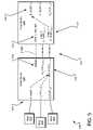
- FIG. 5illustrates example port mappings between a node device 500 and an edge switch 502 interconnected via trunked communication links after disablement of a master N_PORT in a trunk.
- Hosts 518i.e., example end nodes
- the node device 500has detected that communications via a master N_PORT 506 have been disabled.
- a new master N_PORT 508is designated from those trunked ports that are not disabled.
- a mapping table of the node device 500 that maps each of the F_PORTs 504 to the master N_PORT 506 of the trunked group in the node device 500is modified to map each of the F_PORTs 504 to the new master N_PORT 508 .
- the incoming frames from the hosts 518are still forwarded internally to the transmit queue of the trunk.
- the transmit logic of the new master N_PORT 508 and other slave N_PORTsstill extracts the frames from the transmit queue of trunk and transmits these frames in-order through the trunked communications links 510 .
- the trunk bandwidthhas been reduced through lost of the communications link 520 connected to the disabled N_PORT 506 .
- FIG. 5only shows 3 pairs of N_PORTs and F_PORTs and only 3 trunked communication links 510 , it should be understood that additional slave N_PORT/F_PORT pairs may be present in the trunk, and that all port pairs that are not disabled may continue to transfer frames between the node device 500 and the edge switch 502 .
- the master F_PORT designationis also modified on the edge switch 502 , but all incoming frames received via the trunk group are still collected in the receive queue associated with the trunk. As such, the edge switch 502 receives the frames via its new master F_PORT 512 and other slave F_PORT (not shown) and collects the frames into the receive queue of the trunk. The frames are then forwarded from this receive queue through one or more E_PORTs 516 of the edge switch 502 .
- FIG. 6illustrates example port mappings between a node device 600 and an edge switch 602 interconnected via trunked communication links 610 , in the opposite direction as described with regard to FIG. 3 .
- a break 601 illustrated in FIG. 6represents operative connectivity through a fabric.
- Storage device 619i.e., an example end node
- E_PORT 616of the edge switch 602 .
- Internal routing logicuses an Area routing table of the edge switch 602 to forward the incoming frames to a transmit queue associated with the trunked group in the edge switch 602 in accordance with this routing table.
- the transmit logic of the master F_PORT 612 , the slave F_PORT 614 , and other slave F_PORTsextracts the frames from the transmit queue of the trunk and transmits these frames in-order through the trunked communications links 610 .
- FIG. 6only shows 3 pairs of N_PORTs and F_PORTs and only 3 trunked communication links 610 , it should be understood that additional slave N_PORT/F_PORT pairs may be present in the trunk, and that all port pairs that are not disabled may continue to transfer frames between the node device 600 and the edge switch 602 .
- the node device 600receives the frames via its master N_PORT 606 and slave N_PORT 608 and collects the frames into a receive queue associated with the trunk in the node device 600 . The frames are then forwarded from this receive queue through the appropriate F_PORT of the node device 600 .
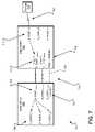
- FIG. 7illustrates example port mappings between a node device 700 and an edge switch 702 interconnected via trunked communication links 710 after disablement of a slave F_PORT in a trunk, in the opposite direction as described with regard to FIG. 4 .
- a break 701 illustrated in FIG. 7represents operative connectivity through a fabric.
- Storage device 719i.e., an example end node
- E_PORT 716 of the edge switch 702is still operatively connected through a switching fabric to an E_PORT 716 of the edge switch 702 .
- the edge switch 702has detected that communications via a slave F_PORT 714 have been disabled.
- Internal routing logicstill uses an Area routing table of the edge switch 702 to forward the incoming frames in accordance with the F_PORT identifier associated with the trunked F_PORTs to the transmit queue associated with the trunk group in the edge switch 702 .
- the transmit logic of the master F_PORT 712 and other slave F_PORTsextracts the frames from the transmit queue of the trunk and transmits these frames in-order through the trunked communications links 710 .
- the trunk bandwidthhas been reduced through lost of the communications link 720 connected to the disabled slave F_PORT 714 . Note:
- a disabled link(e.g., a disconnected or cut cable) can be detected by the hardware of the edge switch 702 .
- the hardware of the edge switchdetects an interruption in communications and notifies the software associated with the affected port via an interrupt.
- the edge switch's operating system kernelservices the interrupt by notifying the port ASIC modules associated with the affected port. If the port is a master port (e.g., as indicated in a register setting in the ASIC or in a configuration datastore), the ASIC module designates a new master port within the trunk. A new master state change notification, containing the old master port and the new master port, is then sent to the node device's application software, although no change to the Area routing table need be made.
- the node device 700receives the frames via its master N_PORT 706 and other slave N_PORTs and collects the frames into a receive queue associated with the trunk in the node device 700 . The frames are then forwarded from this receive queue through the appropriate F_PORT of the node device 700 .
- FIG. 8illustrates example port mappings between a node device 800 and an edge switch 802 interconnected via trunked communication links after disablement of a master F_PORT in a trunk, in the opposite direction as described with regard to FIG. 5 .
- a break 801 illustrated in FIG. 8represents operative connectivity through a fabric.
- a storage device 819i.e., an example end node
- the edge switch 802has detected that communications via the master F_PORT 812 have been disabled.
- the edge switch 802designates a new master port.
- the master N_PORT designationis also modified on the node device 800 , but all incoming frames received via the trunk group are still collected in the receive queue associated with the trunk in the node device 800 .
- the node device 800receives the frames via its new master N_PORT 808 and other slave N_PORT (not shown) and collects the frames into the receive queue of the trunk. The frames are then forwarded from this receive queue through the appropriate F_PORT of the node device 800 .
- FIG. 9illustrates example communications/operations 900 between a node device and an edge switch for initializing F_PORT trunking.
- a node deviceconnects to an edge switch with communications flowing back and forth between the two devices via one or more communications links connected to device ports.
- operations 902 , 904 , 906 , 908 , 910 , 912 , 914 , and 916are performed by all of the ports (i.e., master and slave) in the trunk groups, and then the master ports only need perform operations 918 and 920 .
- N_PORTs of the node devicetransmits a request to the edge switch requesting support for port trunking (e.g., a fabric login request (FLOGI) with the vendor bit set to 1, in one implementation).
- the vendor bitmay be implemented as bit 29 (Valid Vendor Version) of the second word of the Common Service Parameters of the FLOGI Payload, although other implementations and standards may be employed.
- FLOGI ACCfabric login acceptance
- DIDdestination port identifier
- exchange operations 906 and 908the edge switch and the node device negotiate exchange link parameters (ELPs) to establish a link between the corresponding ports of each device.
- ELPsexchange link parameters
- a trunk initialization operation 910 in the edge switchstarts a trunking protocol with the node device.
- a trunking protocol completion operation 912 in the node deviceends the trunking protocol with the edge switch.
- a reset operation 914sends a link reset comment from the edge switch to the node device.
- a response operation 916sends a link reset response from the node device to the edge switch.
- slave port communications in the initialization processend here and only the master ports continue for the last pair of communications.
- the node deviceissues another fabric login request (FLOGI) with the vendor bit set to 0.
- the edge switchresponds with a fabric login acceptance indicating a destination port identifier (DID) shared by all of the trunked F_PORTs in the edge switch.
- DIDdestination port identifier
- this destinationtakes the form of “DDAAPP” where “DD” represents a Domain identifier, “AA” represents an Area identifier, and “PP” represents a Port identifier. Nevertheless, as noted previously, all of the trunked F_PORTs share the same DID, preventing other subsequent fabric logins from being executed at a trunked F_PORT.
- the embodiments of the invention described hereinare implemented as logical steps in one or more computer systems.
- the logical operations of the present inventionare implemented (1) as a sequence of processor-implemented steps executing in one or more computer systems and (2) as interconnected machine or circuit modules within one or more computer systems.
- the implementationis a matter of choice, dependent on the performance requirements of the computer system implementing the invention. Accordingly, the logical operations making up the embodiments of the invention described herein are referred to variously as operations, steps, objects, or modules.
- logical operationsmay be performed in any order, unless explicitly claimed otherwise or a specific order is inherently necessitated by the claim language.
Landscapes
- Engineering & Computer Science (AREA)
- Computer Networks & Wireless Communication (AREA)
- Signal Processing (AREA)
- Small-Scale Networks (AREA)
Abstract
Description
Claims (38)
Priority Applications (1)
| Application Number | Priority Date | Filing Date | Title |
|---|---|---|---|
| US12/245,269US8223633B2 (en) | 2008-10-03 | 2008-10-03 | Port trunking at a fabric boundary |
Applications Claiming Priority (1)
| Application Number | Priority Date | Filing Date | Title |
|---|---|---|---|
| US12/245,269US8223633B2 (en) | 2008-10-03 | 2008-10-03 | Port trunking at a fabric boundary |
Publications (2)
| Publication Number | Publication Date |
|---|---|
| US20100085981A1 US20100085981A1 (en) | 2010-04-08 |
| US8223633B2true US8223633B2 (en) | 2012-07-17 |
Family
ID=42075768
Family Applications (1)
| Application Number | Title | Priority Date | Filing Date |
|---|---|---|---|
| US12/245,269Active2029-07-24US8223633B2 (en) | 2008-10-03 | 2008-10-03 | Port trunking at a fabric boundary |
Country Status (1)
| Country | Link |
|---|---|
| US (1) | US8223633B2 (en) |
Cited By (1)
| Publication number | Priority date | Publication date | Assignee | Title |
|---|---|---|---|---|
| US10348519B2 (en) | 2014-11-20 | 2019-07-09 | Hewlett Packard Enterprise Development Lp | Virtual target port aggregation |
Families Citing this family (54)
| Publication number | Priority date | Publication date | Assignee | Title |
|---|---|---|---|---|
| US7948920B2 (en)* | 2009-03-03 | 2011-05-24 | Cisco Technology, Inc. | Trunking with port aggregation for fabric ports in a fibre channel fabric and attached devices |
| US8351448B1 (en)* | 2009-03-24 | 2013-01-08 | Qlogic, Corporation | Method and system for extended port addressing |
| US8706905B1 (en)* | 2009-08-24 | 2014-04-22 | Qlogic, Corporation | Method and system for routing information in a network |
| US9270486B2 (en) | 2010-06-07 | 2016-02-23 | Brocade Communications Systems, Inc. | Name services for virtual cluster switching |
| US9769016B2 (en) | 2010-06-07 | 2017-09-19 | Brocade Communications Systems, Inc. | Advanced link tracking for virtual cluster switching |
| US8867552B2 (en) | 2010-05-03 | 2014-10-21 | Brocade Communications Systems, Inc. | Virtual cluster switching |
| US9716672B2 (en) | 2010-05-28 | 2017-07-25 | Brocade Communications Systems, Inc. | Distributed configuration management for virtual cluster switching |
| US9806906B2 (en) | 2010-06-08 | 2017-10-31 | Brocade Communications Systems, Inc. | Flooding packets on a per-virtual-network basis |
| US9807031B2 (en) | 2010-07-16 | 2017-10-31 | Brocade Communications Systems, Inc. | System and method for network configuration |
| US8898333B1 (en) | 2010-08-31 | 2014-11-25 | Juniper Networks, Inc. | Methods and apparatus related to a virtual multi-hop network topology emulated within a data center |
| US9736085B2 (en) | 2011-08-29 | 2017-08-15 | Brocade Communications Systems, Inc. | End-to end lossless Ethernet in Ethernet fabric |
| US8797897B1 (en) | 2011-09-30 | 2014-08-05 | Juniper Networks, Inc. | Methods and apparatus with virtual identifiers for physical switches in a virtual chassis |
| US9450870B2 (en) | 2011-11-10 | 2016-09-20 | Brocade Communications Systems, Inc. | System and method for flow management in software-defined networks |
| US8621095B1 (en)* | 2011-12-20 | 2013-12-31 | Cisco Technology, Inc. | Fibre channel virtualization zone |
| US8995272B2 (en) | 2012-01-26 | 2015-03-31 | Brocade Communication Systems, Inc. | Link aggregation in software-defined networks |
| US9742693B2 (en) | 2012-02-27 | 2017-08-22 | Brocade Communications Systems, Inc. | Dynamic service insertion in a fabric switch |
| US9154416B2 (en) | 2012-03-22 | 2015-10-06 | Brocade Communications Systems, Inc. | Overlay tunnel in a fabric switch |
| US9374301B2 (en) | 2012-05-18 | 2016-06-21 | Brocade Communications Systems, Inc. | Network feedback in software-defined networks |
| US10277464B2 (en) | 2012-05-22 | 2019-04-30 | Arris Enterprises Llc | Client auto-configuration in a multi-switch link aggregation |
| US9401872B2 (en) | 2012-11-16 | 2016-07-26 | Brocade Communications Systems, Inc. | Virtual link aggregations across multiple fabric switches |
| US9548926B2 (en) | 2013-01-11 | 2017-01-17 | Brocade Communications Systems, Inc. | Multicast traffic load balancing over virtual link aggregation |
| US9413691B2 (en) | 2013-01-11 | 2016-08-09 | Brocade Communications Systems, Inc. | MAC address synchronization in a fabric switch |
| US9565099B2 (en) | 2013-03-01 | 2017-02-07 | Brocade Communications Systems, Inc. | Spanning tree in fabric switches |
| WO2014145750A1 (en) | 2013-03-15 | 2014-09-18 | Brocade Communications Systems, Inc. | Scalable gateways for a fabric switch |
| US9699001B2 (en) | 2013-06-10 | 2017-07-04 | Brocade Communications Systems, Inc. | Scalable and segregated network virtualization |
| US20150023359A1 (en)* | 2013-07-19 | 2015-01-22 | Brocade Communications Systems, Inc. | Edge extension of an ethernet fabric switch |
| US9806949B2 (en) | 2013-09-06 | 2017-10-31 | Brocade Communications Systems, Inc. | Transparent interconnection of Ethernet fabric switches |
| US9467304B2 (en) | 2013-10-04 | 2016-10-11 | Brocade Communications Systems, Inc. | 128 gigabit fibre channel speed negotiation |
| US9912612B2 (en) | 2013-10-28 | 2018-03-06 | Brocade Communications Systems LLC | Extended ethernet fabric switches |
| US9548873B2 (en) | 2014-02-10 | 2017-01-17 | Brocade Communications Systems, Inc. | Virtual extensible LAN tunnel keepalives |
| US10581758B2 (en) | 2014-03-19 | 2020-03-03 | Avago Technologies International Sales Pte. Limited | Distributed hot standby links for vLAG |
| US10476698B2 (en) | 2014-03-20 | 2019-11-12 | Avago Technologies International Sales Pte. Limited | Redundent virtual link aggregation group |
| US10063473B2 (en) | 2014-04-30 | 2018-08-28 | Brocade Communications Systems LLC | Method and system for facilitating switch virtualization in a network of interconnected switches |
| US9800471B2 (en) | 2014-05-13 | 2017-10-24 | Brocade Communications Systems, Inc. | Network extension groups of global VLANs in a fabric switch |
| US10616108B2 (en) | 2014-07-29 | 2020-04-07 | Avago Technologies International Sales Pte. Limited | Scalable MAC address virtualization |
| US9807007B2 (en) | 2014-08-11 | 2017-10-31 | Brocade Communications Systems, Inc. | Progressive MAC address learning |
| US9699029B2 (en) | 2014-10-10 | 2017-07-04 | Brocade Communications Systems, Inc. | Distributed configuration management in a switch group |
| US9942097B2 (en) | 2015-01-05 | 2018-04-10 | Brocade Communications Systems LLC | Power management in a network of interconnected switches |
| US10003552B2 (en) | 2015-01-05 | 2018-06-19 | Brocade Communications Systems, Llc. | Distributed bidirectional forwarding detection protocol (D-BFD) for cluster of interconnected switches |
| US9807005B2 (en) | 2015-03-17 | 2017-10-31 | Brocade Communications Systems, Inc. | Multi-fabric manager |
| US10038592B2 (en) | 2015-03-17 | 2018-07-31 | Brocade Communications Systems LLC | Identifier assignment to a new switch in a switch group |
| US10579406B2 (en) | 2015-04-08 | 2020-03-03 | Avago Technologies International Sales Pte. Limited | Dynamic orchestration of overlay tunnels |
| US10439929B2 (en) | 2015-07-31 | 2019-10-08 | Avago Technologies International Sales Pte. Limited | Graceful recovery of a multicast-enabled switch |
| US10171303B2 (en) | 2015-09-16 | 2019-01-01 | Avago Technologies International Sales Pte. Limited | IP-based interconnection of switches with a logical chassis |
| US9912614B2 (en) | 2015-12-07 | 2018-03-06 | Brocade Communications Systems LLC | Interconnection of switches based on hierarchical overlay tunneling |
| US10237090B2 (en) | 2016-10-28 | 2019-03-19 | Avago Technologies International Sales Pte. Limited | Rule-based network identifier mapping |
| EP3541017B1 (en)* | 2018-03-13 | 2021-11-10 | Nokia Solutions and Networks Oy | Method and apparatus for monitoring a telecommunication network |
| US10855594B2 (en)* | 2018-07-13 | 2020-12-01 | Dell Products L.P. | Fibre Channel Forwarder load balancing system |
| US12192121B2 (en) | 2019-03-18 | 2025-01-07 | Brightways Corporation | Hyperscale switch element (HSS) for data center network switching |
| US10630606B1 (en)* | 2019-03-18 | 2020-04-21 | Brightways Corporation | System, method and architecture for data center network switching |
| US11403247B2 (en)* | 2019-09-10 | 2022-08-02 | GigaIO Networks, Inc. | Methods and apparatus for network interface fabric send/receive operations |
| US11206468B2 (en)* | 2019-09-12 | 2021-12-21 | Dell Products L.P. | Fibre channel forwarder failover and load balancing system |
| EP4049143A4 (en) | 2019-10-25 | 2024-02-21 | GigaIO Networks, Inc. | Methods and apparatus for dma engine descriptors for high speed data systems |
| CN112579007B (en)* | 2020-12-26 | 2024-10-29 | 中国建设银行股份有限公司 | Method and device for acquiring storage full link and electronic equipment |
Citations (40)
| Publication number | Priority date | Publication date | Assignee | Title |
|---|---|---|---|---|
| US4782483A (en) | 1986-11-14 | 1988-11-01 | International Computers Limited | Data transmission system and method of passing role of primary station |
| EP0465090A1 (en) | 1990-07-03 | 1992-01-08 | AT&T Corp. | Congestion control for connectionless traffic in data networks via alternate routing |
| WO1993019550A1 (en) | 1992-03-17 | 1993-09-30 | Telefonaktiebolaget Lm Ericsson | A method of grouping links in a packet switch |
| US5282202A (en) | 1991-03-28 | 1994-01-25 | Sprint International Communications Corp. | Composite frame reconfiguration in integrated services networks |
| US5383181A (en) | 1991-10-31 | 1995-01-17 | Nec Corporation | Packet switching system capable of reducing a delay time for each packet |
| US5425020A (en) | 1993-11-04 | 1995-06-13 | International Business Machines Corporation | Skew measurement for receiving frame-groups |
| US5455831A (en) | 1992-02-20 | 1995-10-03 | International Business Machines Corporation | Frame group transmission and reception for parallel/serial buses |
| US5519695A (en) | 1994-10-27 | 1996-05-21 | Hewlett-Packard Company | Switch element for fiber channel networks |
| US5649110A (en) | 1994-11-07 | 1997-07-15 | Ben-Nun; Michael | Traffic shaping system with virtual circuit table time stamps for asynchronous transfer mode networks |
| US5649108A (en) | 1993-11-30 | 1997-07-15 | Nec Corporation | Combined progressive and source routing control for connection-oriented communications networks |
| WO1998007259A1 (en) | 1996-08-14 | 1998-02-19 | Cabletron Systems, Inc. | Load sharing for redundant networks |
| US6016310A (en) | 1997-06-30 | 2000-01-18 | Sun Microsystems, Inc. | Trunking support in a high performance network device |
| US6104700A (en) | 1997-08-29 | 2000-08-15 | Extreme Networks | Policy based quality of service |
| US6104696A (en) | 1998-07-08 | 2000-08-15 | Broadcom Corporation | Method for sending packets between trunk ports of network switches |
| US6233236B1 (en) | 1999-01-12 | 2001-05-15 | Mcdata Corporation | Method and apparatus for measuring traffic within a switch |
| US6240096B1 (en) | 1996-09-11 | 2001-05-29 | Mcdata Corporation | Fibre channel switch employing distributed queuing |
| US6275492B1 (en) | 1996-12-03 | 2001-08-14 | Nortel Networks Limited | Method and apparatus for routing data using router identification information |
| US6400681B1 (en) | 1996-06-20 | 2002-06-04 | Cisco Technology, Inc. | Method and system for minimizing the connection set up time in high speed packet switching networks |
| US6434145B1 (en) | 1998-06-22 | 2002-08-13 | Applied Micro Circuits Corporation | Processing of network data by parallel processing channels |
| US20020131456A1 (en) | 2001-03-16 | 2002-09-19 | Broadcom Corporation | Network interface using programmable delay and frequency doubler |
| US6532212B1 (en) | 2001-09-25 | 2003-03-11 | Mcdata Corporation | Trunking inter-switch links |
| US6549541B1 (en) | 1997-11-04 | 2003-04-15 | Nokia Corporation | Buffer management |
| US20030147385A1 (en)* | 2002-01-28 | 2003-08-07 | Armando Montalvo | Enterprise switching device and method |
| US20030172149A1 (en)* | 2002-01-23 | 2003-09-11 | Andiamo Systems, A Delaware Corporation | Methods and apparatus for implementing virtualization of storage within a storage area network |
| US6628609B2 (en) | 1998-04-30 | 2003-09-30 | Nortel Networks Limited | Method and apparatus for simple IP-layer bandwidth allocation using ingress control of egress bandwidth |
| US6647017B1 (en) | 1997-07-14 | 2003-11-11 | Nokia Corporation | Switching fabric arrangement with time stamp function |
| US6731600B1 (en) | 1999-02-08 | 2004-05-04 | Realnetworks, Inc. | System and method for determining network conditions |
| US20050030948A1 (en) | 2000-02-29 | 2005-02-10 | Mosaid Technologies, Inc. | Link aggregation |
| US6859438B2 (en) | 1998-02-03 | 2005-02-22 | Extreme Networks, Inc. | Policy based quality of service |
| US6865153B1 (en) | 2000-09-20 | 2005-03-08 | Alcatel | Stage-implemented QoS shaping for data communication switch |
| US20050094649A1 (en) | 2003-10-31 | 2005-05-05 | Surya Varanasi | Logical ports in trunking |
| US20050152369A1 (en)* | 1998-07-08 | 2005-07-14 | Broadcom Corporation | Fast flexible filter processor based architecture for a network device |
| US20050169258A1 (en)* | 2004-01-29 | 2005-08-04 | Brocade Communications Systems, Inc. | Fibre channel zoning hardware for directing a data packet to an external processing device |
| US6941252B2 (en) | 2001-03-14 | 2005-09-06 | Mcdata Corporation | Striping data frames across parallel fibre channel links |
| US20050198523A1 (en) | 2004-01-29 | 2005-09-08 | Brocade Communications Systems, Inc. | Isolation switch for fibre channel fabrics in storage area networks |
| US20070130295A1 (en)* | 2005-10-27 | 2007-06-07 | Cisco Technology, Inc. | Technique for implementing virtual fabric membership assignments for devices in a storage area network |
| US7286527B2 (en) | 2002-07-26 | 2007-10-23 | Brocade Communications Systems, Inc. | Method and apparatus for round trip delay measurement in a bi-directional, point-to-point, serial data channel |
| US20080215910A1 (en)* | 2005-08-17 | 2008-09-04 | Nortel Networks Limited | High-Availability Networking with Intelligent Failover |
| US7447198B1 (en) | 2001-04-23 | 2008-11-04 | Brocade Communications Systems, Inc. | Link trunking and measuring link latency in fibre channel fabric |
| US20090092043A1 (en)* | 2007-10-03 | 2009-04-09 | Nortel Networks Limited | Providing an abstraction layer in a cluster switch that includes plural switches |
- 2008
- 2008-10-03USUS12/245,269patent/US8223633B2/enactiveActive
Patent Citations (41)
| Publication number | Priority date | Publication date | Assignee | Title |
|---|---|---|---|---|
| US4782483A (en) | 1986-11-14 | 1988-11-01 | International Computers Limited | Data transmission system and method of passing role of primary station |
| EP0465090A1 (en) | 1990-07-03 | 1992-01-08 | AT&T Corp. | Congestion control for connectionless traffic in data networks via alternate routing |
| US5282202A (en) | 1991-03-28 | 1994-01-25 | Sprint International Communications Corp. | Composite frame reconfiguration in integrated services networks |
| US5383181A (en) | 1991-10-31 | 1995-01-17 | Nec Corporation | Packet switching system capable of reducing a delay time for each packet |
| US5455831A (en) | 1992-02-20 | 1995-10-03 | International Business Machines Corporation | Frame group transmission and reception for parallel/serial buses |
| WO1993019550A1 (en) | 1992-03-17 | 1993-09-30 | Telefonaktiebolaget Lm Ericsson | A method of grouping links in a packet switch |
| US5425020A (en) | 1993-11-04 | 1995-06-13 | International Business Machines Corporation | Skew measurement for receiving frame-groups |
| US5649108A (en) | 1993-11-30 | 1997-07-15 | Nec Corporation | Combined progressive and source routing control for connection-oriented communications networks |
| US5519695A (en) | 1994-10-27 | 1996-05-21 | Hewlett-Packard Company | Switch element for fiber channel networks |
| US5649110A (en) | 1994-11-07 | 1997-07-15 | Ben-Nun; Michael | Traffic shaping system with virtual circuit table time stamps for asynchronous transfer mode networks |
| US6400681B1 (en) | 1996-06-20 | 2002-06-04 | Cisco Technology, Inc. | Method and system for minimizing the connection set up time in high speed packet switching networks |
| WO1998007259A1 (en) | 1996-08-14 | 1998-02-19 | Cabletron Systems, Inc. | Load sharing for redundant networks |
| US6240096B1 (en) | 1996-09-11 | 2001-05-29 | Mcdata Corporation | Fibre channel switch employing distributed queuing |
| US6275492B1 (en) | 1996-12-03 | 2001-08-14 | Nortel Networks Limited | Method and apparatus for routing data using router identification information |
| US6016310A (en) | 1997-06-30 | 2000-01-18 | Sun Microsystems, Inc. | Trunking support in a high performance network device |
| US6647017B1 (en) | 1997-07-14 | 2003-11-11 | Nokia Corporation | Switching fabric arrangement with time stamp function |
| US6104700A (en) | 1997-08-29 | 2000-08-15 | Extreme Networks | Policy based quality of service |
| US6678248B1 (en) | 1997-08-29 | 2004-01-13 | Extreme Networks | Policy based quality of service |
| US6549541B1 (en) | 1997-11-04 | 2003-04-15 | Nokia Corporation | Buffer management |
| US6859438B2 (en) | 1998-02-03 | 2005-02-22 | Extreme Networks, Inc. | Policy based quality of service |
| US6628609B2 (en) | 1998-04-30 | 2003-09-30 | Nortel Networks Limited | Method and apparatus for simple IP-layer bandwidth allocation using ingress control of egress bandwidth |
| US6434145B1 (en) | 1998-06-22 | 2002-08-13 | Applied Micro Circuits Corporation | Processing of network data by parallel processing channels |
| US20050152369A1 (en)* | 1998-07-08 | 2005-07-14 | Broadcom Corporation | Fast flexible filter processor based architecture for a network device |
| US6104696A (en) | 1998-07-08 | 2000-08-15 | Broadcom Corporation | Method for sending packets between trunk ports of network switches |
| US6233236B1 (en) | 1999-01-12 | 2001-05-15 | Mcdata Corporation | Method and apparatus for measuring traffic within a switch |
| US6731600B1 (en) | 1999-02-08 | 2004-05-04 | Realnetworks, Inc. | System and method for determining network conditions |
| US20050030948A1 (en) | 2000-02-29 | 2005-02-10 | Mosaid Technologies, Inc. | Link aggregation |
| US6865153B1 (en) | 2000-09-20 | 2005-03-08 | Alcatel | Stage-implemented QoS shaping for data communication switch |
| US6941252B2 (en) | 2001-03-14 | 2005-09-06 | Mcdata Corporation | Striping data frames across parallel fibre channel links |
| US20020131456A1 (en) | 2001-03-16 | 2002-09-19 | Broadcom Corporation | Network interface using programmable delay and frequency doubler |
| US7447198B1 (en) | 2001-04-23 | 2008-11-04 | Brocade Communications Systems, Inc. | Link trunking and measuring link latency in fibre channel fabric |
| US6532212B1 (en) | 2001-09-25 | 2003-03-11 | Mcdata Corporation | Trunking inter-switch links |
| US20030172149A1 (en)* | 2002-01-23 | 2003-09-11 | Andiamo Systems, A Delaware Corporation | Methods and apparatus for implementing virtualization of storage within a storage area network |
| US20030147385A1 (en)* | 2002-01-28 | 2003-08-07 | Armando Montalvo | Enterprise switching device and method |
| US7286527B2 (en) | 2002-07-26 | 2007-10-23 | Brocade Communications Systems, Inc. | Method and apparatus for round trip delay measurement in a bi-directional, point-to-point, serial data channel |
| US20050094649A1 (en) | 2003-10-31 | 2005-05-05 | Surya Varanasi | Logical ports in trunking |
| US20050198523A1 (en) | 2004-01-29 | 2005-09-08 | Brocade Communications Systems, Inc. | Isolation switch for fibre channel fabrics in storage area networks |
| US20050169258A1 (en)* | 2004-01-29 | 2005-08-04 | Brocade Communications Systems, Inc. | Fibre channel zoning hardware for directing a data packet to an external processing device |
| US20080215910A1 (en)* | 2005-08-17 | 2008-09-04 | Nortel Networks Limited | High-Availability Networking with Intelligent Failover |
| US20070130295A1 (en)* | 2005-10-27 | 2007-06-07 | Cisco Technology, Inc. | Technique for implementing virtual fabric membership assignments for devices in a storage area network |
| US20090092043A1 (en)* | 2007-10-03 | 2009-04-09 | Nortel Networks Limited | Providing an abstraction layer in a cluster switch that includes plural switches |
Non-Patent Citations (15)
| Title |
|---|
| "Fabric Shortest Path First Version 2" by Brocade Communication Systems, Inc. Revision 0.2, May 23, 2000. |
| American National Standard for Information Systems, "Fibre Channel Fabric Generic Requirements (FC-FG) Rev. 3.5." Aug. 7, 1996. |
| Braden et al., Integrated Services in the Internet Architecture: an Overview, Network Working Group, RFC 1633, Jul. 1994, 28 pages. |
| Deficit Round Robin, 1 page, http://en.wikipedia.org/wiki/deficit-weighted-round-robin. |
| Dell Tape: Backup With Custom Barcodes, 4 pages, http://searchdatabackup.techtarget.com/generic/0,295582,sid187-gci1300168,00.html. |
| Differentiated Services, 7 pages, http://en.wikipedia.org/wiki/Differentiated-services. |
| Floyd et al.,, Link-sharing and Resource Management Models for Packet Networks, IEEE/ACM Transactions on Networking, vol. 3, No. 4, Aug. 1995, 22 pages. |
| I am 19374: Chapter 2 Virtual LANs and VLAN Trunking, 6 pages, http://ooteum.blogspot.com/2008/12/chapter-2-virtual-lans-and-vlan.html. |
| IEEE 802.1p, 1 page, http://en.wikipedia.org/wiki/IEEE-802.1p. |
| IEEE 802.1Q, 3 pages, http://en.wikipedia.org/wiki/IEEE-802.1Q. |
| Increasing Intelligence within the SAN fabric, Internet Citation, Jun. 2001, XP002251362, Retrieved from the Internet Aug. 14, 2003: URL:http://www.brocade.com/san.white-papers/pdf/IncreadingIntelligenceWithinSAN.pdf. |
| Overland Storage, Data Replication, 2 pages, http://overlandstorage.com/topics/Replication.html. |
| Rosenstein, Ariel, Storage Channel News: A Case for remote data replication, ArticleAlley.com, Sep. 28, 2006, 3 pages, http://searchstoragechannel.techtarget.com/news/article/0,289142,sid98-gci1219253.00.html. |
| Supplementary European Search Report for EP 02747985, dated Nov. 2, 2006, 4 pages. |
| TCP Session: Chapter 6, http://74.125.47.132/search?q=cache:tiPkgJqatWSAJ:research.microsoft.com/en-us/um/people/padmanab.thesis/sessions.ps.gz+%22TCP+SESSION%22+%22CHAPTER+6%22+%22PROS+AND+CONS%22&cd+1&hl=en&ct+clnk&gl=us&client+firefox-a, pp. 96-129. |
Cited By (1)
| Publication number | Priority date | Publication date | Assignee | Title |
|---|---|---|---|---|
| US10348519B2 (en) | 2014-11-20 | 2019-07-09 | Hewlett Packard Enterprise Development Lp | Virtual target port aggregation |
Also Published As
| Publication number | Publication date |
|---|---|
| US20100085981A1 (en) | 2010-04-08 |
Similar Documents
| Publication | Publication Date | Title |
|---|---|---|
| US8223633B2 (en) | Port trunking at a fabric boundary | |
| US11256644B2 (en) | Dynamically changing configuration of data processing unit when connected to storage device or computing device | |
| EP2912805B1 (en) | Network virtualization over infiniband | |
| US7944812B2 (en) | Redundant intermediary switch solution for detecting and managing fibre channel over ethernet FCoE switch failures | |
| US9083642B2 (en) | Systems and methods for optimizing layer three routing in an information handling system | |
| US7580415B2 (en) | Aggregation of hybrid network resources operable to support both offloaded and non-offloaded connections | |
| US8942139B2 (en) | Support for converged traffic over ethernet link aggregation (LAG) | |
| US9426546B2 (en) | Maintaining a fabric name across a distributed switch | |
| US7877512B2 (en) | Isolation switch for fibre channel fabrics in storage area networks | |
| CN101820358B (en) | High availability and multipathing for fibre channel over Ethernet | |
| US7720064B1 (en) | Method and system for processing network and storage data | |
| US8891516B2 (en) | Extended link aggregation (LAG) for use in multiple switches | |
| US8873369B2 (en) | Fiber channel 1:N redundancy | |
| US9172602B1 (en) | Method and system for auto-negotiation | |
| US11336508B2 (en) | Transparent failover in a network interface controller | |
| US8705351B1 (en) | Method and system for load balancing in networks | |
| US8812707B2 (en) | Transmitting internet protocol over SCSI in a high availability cluster | |
| US8203964B2 (en) | Asynchronous event notification | |
| US9397958B2 (en) | FCoE VN—port virtualizer | |
| US9577872B2 (en) | Fiber channel 1:N redundancy | |
| US10367681B2 (en) | Maintenance of data forwarder connection state information | |
| US8225004B1 (en) | Method and system for processing network and storage data | |
| US9426097B1 (en) | Facilitating communication between devices in a network |
Legal Events
| Date | Code | Title | Description |
|---|---|---|---|
| AS | Assignment | Owner name:BROCADE COMMUNICATIONS SYSTEMS, INC.,CALIFORNIA Free format text:ASSIGNMENT OF ASSIGNORS INTEREST;ASSIGNORS:GUPTA, RAJNISH;PHAM, NHAN T.;DANI, AMOD K.;AND OTHERS;SIGNING DATES FROM 20080924 TO 20080926;REEL/FRAME:021639/0310 Owner name:BROCADE COMMUNICATIONS SYSTEMS, INC., CALIFORNIA Free format text:ASSIGNMENT OF ASSIGNORS INTEREST;ASSIGNORS:GUPTA, RAJNISH;PHAM, NHAN T.;DANI, AMOD K.;AND OTHERS;SIGNING DATES FROM 20080924 TO 20080926;REEL/FRAME:021639/0310 | |
| STCF | Information on status: patent grant | Free format text:PATENTED CASE | |
| REMI | Maintenance fee reminder mailed | ||
| FPAY | Fee payment | Year of fee payment:4 | |
| SULP | Surcharge for late payment | ||
| AS | Assignment | Owner name:BROCADE COMMUNICATIONS SYSTEMS LLC, CALIFORNIA Free format text:CHANGE OF NAME;ASSIGNOR:BROCADE COMMUNICATIONS SYSTEMS, INC.;REEL/FRAME:044891/0536 Effective date:20171128 | |
| AS | Assignment | Owner name:AVAGO TECHNOLOGIES INTERNATIONAL SALES PTE. LIMITED, SINGAPORE Free format text:ASSIGNMENT OF ASSIGNORS INTEREST;ASSIGNOR:BROCADE COMMUNICATIONS SYSTEMS LLC;REEL/FRAME:047270/0247 Effective date:20180905 Owner name:AVAGO TECHNOLOGIES INTERNATIONAL SALES PTE. LIMITE Free format text:ASSIGNMENT OF ASSIGNORS INTEREST;ASSIGNOR:BROCADE COMMUNICATIONS SYSTEMS LLC;REEL/FRAME:047270/0247 Effective date:20180905 | |
| MAFP | Maintenance fee payment | Free format text:PAYMENT OF MAINTENANCE FEE, 8TH YEAR, LARGE ENTITY (ORIGINAL EVENT CODE: M1552); ENTITY STATUS OF PATENT OWNER: LARGE ENTITY Year of fee payment:8 | |
| MAFP | Maintenance fee payment | Free format text:PAYMENT OF MAINTENANCE FEE, 12TH YEAR, LARGE ENTITY (ORIGINAL EVENT CODE: M1553); ENTITY STATUS OF PATENT OWNER: LARGE ENTITY Year of fee payment:12 |