US8223117B2 - Method and apparatus to control display brightness with ambient light correction - Google Patents
Method and apparatus to control display brightness with ambient light correctionDownload PDFInfo
- Publication number
- US8223117B2 US8223117B2US12/336,990US33699008AUS8223117B2US 8223117 B2US8223117 B2US 8223117B2US 33699008 AUS33699008 AUS 33699008AUS 8223117 B2US8223117 B2US 8223117B2
- Authority
- US
- United States
- Prior art keywords
- signal
- brightness control
- ambient light
- control circuit
- brightness
- Prior art date
- Legal status (The legal status is an assumption and is not a legal conclusion. Google has not performed a legal analysis and makes no representation as to the accuracy of the status listed.)
- Active, expires
Links
- 238000012937correctionMethods0.000titleclaimsdescription15
- 238000000034methodMethods0.000titleclaimsdescription11
- 238000002955isolationMethods0.000claimsdescription11
- 230000007423decreaseEffects0.000claimsdescription7
- 238000005286illuminationMethods0.000claimsdescription4
- 238000001228spectrumMethods0.000claimsdescription3
- 239000004973liquid crystal related substanceSubstances0.000claimsdescription2
- 230000001052transient effectEffects0.000claimsdescription2
- 230000001419dependent effectEffects0.000claims2
- 230000035945sensitivityEffects0.000claims1
- 230000000007visual effectEffects0.000abstractdescription6
- 239000003990capacitorSubstances0.000description24
- 238000010586diagramMethods0.000description12
- 238000009499grossingMethods0.000description11
- 230000008901benefitEffects0.000description6
- 230000000694effectsEffects0.000description5
- 239000004065semiconductorSubstances0.000description5
- 230000003321amplificationEffects0.000description4
- 238000003199nucleic acid amplification methodMethods0.000description4
- 208000003464asthenopiaDiseases0.000description2
- 238000006243chemical reactionMethods0.000description2
- 230000007850degenerationEffects0.000description2
- 206010016256fatigueDiseases0.000description2
- 230000000737periodic effectEffects0.000description2
- 238000012358sourcingMethods0.000description2
- 230000003595spectral effectEffects0.000description2
- 206010063493Premature ageingDiseases0.000description1
- 208000032038Premature agingDiseases0.000description1
- 238000013459approachMethods0.000description1
- 230000003247decreasing effectEffects0.000description1
- 238000001914filtrationMethods0.000description1
- 238000012986modificationMethods0.000description1
- 230000004048modificationEffects0.000description1
- 238000012545processingMethods0.000description1
- 230000035484reaction timeEffects0.000description1
- 230000035882stressEffects0.000description1
- 238000006467substitution reactionMethods0.000description1
- 239000000758substrateSubstances0.000description1
- 230000007704transitionEffects0.000description1
Images


Classifications
- G—PHYSICS
- G09—EDUCATION; CRYPTOGRAPHY; DISPLAY; ADVERTISING; SEALS
- G09G—ARRANGEMENTS OR CIRCUITS FOR CONTROL OF INDICATING DEVICES USING STATIC MEANS TO PRESENT VARIABLE INFORMATION
- G09G3/00—Control arrangements or circuits, of interest only in connection with visual indicators other than cathode-ray tubes
- G09G3/20—Control arrangements or circuits, of interest only in connection with visual indicators other than cathode-ray tubes for presentation of an assembly of a number of characters, e.g. a page, by composing the assembly by combination of individual elements arranged in a matrix no fixed position being assigned to or needed to be assigned to the individual characters or partial characters
- G09G3/34—Control arrangements or circuits, of interest only in connection with visual indicators other than cathode-ray tubes for presentation of an assembly of a number of characters, e.g. a page, by composing the assembly by combination of individual elements arranged in a matrix no fixed position being assigned to or needed to be assigned to the individual characters or partial characters by control of light from an independent source
- G09G3/3406—Control of illumination source
- G—PHYSICS
- G09—EDUCATION; CRYPTOGRAPHY; DISPLAY; ADVERTISING; SEALS
- G09G—ARRANGEMENTS OR CIRCUITS FOR CONTROL OF INDICATING DEVICES USING STATIC MEANS TO PRESENT VARIABLE INFORMATION
- G09G2300/00—Aspects of the constitution of display devices
- G09G2300/04—Structural and physical details of display devices
- G09G2300/0439—Pixel structures
- G09G2300/0456—Pixel structures with a reflective area and a transmissive area combined in one pixel, such as in transflectance pixels
- G—PHYSICS
- G09—EDUCATION; CRYPTOGRAPHY; DISPLAY; ADVERTISING; SEALS
- G09G—ARRANGEMENTS OR CIRCUITS FOR CONTROL OF INDICATING DEVICES USING STATIC MEANS TO PRESENT VARIABLE INFORMATION
- G09G2320/00—Control of display operating conditions
- G09G2320/06—Adjustment of display parameters
- G09G2320/0606—Manual adjustment
- G—PHYSICS
- G09—EDUCATION; CRYPTOGRAPHY; DISPLAY; ADVERTISING; SEALS
- G09G—ARRANGEMENTS OR CIRCUITS FOR CONTROL OF INDICATING DEVICES USING STATIC MEANS TO PRESENT VARIABLE INFORMATION
- G09G2320/00—Control of display operating conditions
- G09G2320/06—Adjustment of display parameters
- G09G2320/0626—Adjustment of display parameters for control of overall brightness
- G—PHYSICS
- G09—EDUCATION; CRYPTOGRAPHY; DISPLAY; ADVERTISING; SEALS
- G09G—ARRANGEMENTS OR CIRCUITS FOR CONTROL OF INDICATING DEVICES USING STATIC MEANS TO PRESENT VARIABLE INFORMATION
- G09G2360/00—Aspects of the architecture of display systems
- G09G2360/14—Detecting light within display terminals, e.g. using a single or a plurality of photosensors
- G09G2360/144—Detecting light within display terminals, e.g. using a single or a plurality of photosensors the light being ambient light
- G—PHYSICS
- G09—EDUCATION; CRYPTOGRAPHY; DISPLAY; ADVERTISING; SEALS
- G09G—ARRANGEMENTS OR CIRCUITS FOR CONTROL OF INDICATING DEVICES USING STATIC MEANS TO PRESENT VARIABLE INFORMATION
- G09G3/00—Control arrangements or circuits, of interest only in connection with visual indicators other than cathode-ray tubes
- G09G3/20—Control arrangements or circuits, of interest only in connection with visual indicators other than cathode-ray tubes for presentation of an assembly of a number of characters, e.g. a page, by composing the assembly by combination of individual elements arranged in a matrix no fixed position being assigned to or needed to be assigned to the individual characters or partial characters
- G09G3/22—Control arrangements or circuits, of interest only in connection with visual indicators other than cathode-ray tubes for presentation of an assembly of a number of characters, e.g. a page, by composing the assembly by combination of individual elements arranged in a matrix no fixed position being assigned to or needed to be assigned to the individual characters or partial characters using controlled light sources
- G—PHYSICS
- G09—EDUCATION; CRYPTOGRAPHY; DISPLAY; ADVERTISING; SEALS
- G09G—ARRANGEMENTS OR CIRCUITS FOR CONTROL OF INDICATING DEVICES USING STATIC MEANS TO PRESENT VARIABLE INFORMATION
- G09G3/00—Control arrangements or circuits, of interest only in connection with visual indicators other than cathode-ray tubes
- G09G3/20—Control arrangements or circuits, of interest only in connection with visual indicators other than cathode-ray tubes for presentation of an assembly of a number of characters, e.g. a page, by composing the assembly by combination of individual elements arranged in a matrix no fixed position being assigned to or needed to be assigned to the individual characters or partial characters
- G09G3/34—Control arrangements or circuits, of interest only in connection with visual indicators other than cathode-ray tubes for presentation of an assembly of a number of characters, e.g. a page, by composing the assembly by combination of individual elements arranged in a matrix no fixed position being assigned to or needed to be assigned to the individual characters or partial characters by control of light from an independent source
- G09G3/36—Control arrangements or circuits, of interest only in connection with visual indicators other than cathode-ray tubes for presentation of an assembly of a number of characters, e.g. a page, by composing the assembly by combination of individual elements arranged in a matrix no fixed position being assigned to or needed to be assigned to the individual characters or partial characters by control of light from an independent source using liquid crystals
Definitions
- the present inventionrelates to brightness control in a visual information display system, and more particularly relates to adjusting the brightness level to compensate for changes in ambient lighting.
- Backlightis needed to illuminate a screen to make a visible display in liquid crystal display (LCD) applications.
- LCDliquid crystal display
- the ability to read the displayis hampered under conditions of high ambient room lighting.
- Ambient lightingreflects off the surface of the LCD and adds a bias to the light produced by the LCD, which reduces the display contrast to give the LCD a washed-out appearance.
- the conditioncan be improved by increasing the brightness of the backlight for the LCD, thereby making the light provided by the LCD brighter in comparison to the reflected light off the LCD surface.
- the backlightshould be adjusted to be brighter for high ambient lighting conditions and less bright for low ambient lighting conditions to maintain consistent perceived brightness.
- One method of reducing power consumption, and therefore extending battery run timeis to reduce the backlight brightness of a LCD under low ambient lighting conditions.
- the backlightcan operate at a lower brightness level for low ambient lighting conditions because light reflections caused by the ambient light are lower and produce less of a washed-out effect.
- an ambient light sensoris used in a closed-loop configuration to adjust the backlight level in response to the ambient light level.
- These systemsusually do not take into account user preferences. These systems are crude in implementation and do not adapt well to user preferences which may vary under various levels of eye fatigue.
- the present inventionis a light sensor control system that provides the capability for a fully automatic and fully adaptable method of adjusting display brightness in response to varying ambient lighting conditions in combination with various user preferences.
- the mathematical product of a light sensor output and a user selectable brightness controlcan be used to vary backlight intensity in LCD applications.
- Using the product of the light sensor output and the user selectable brightness controladvantageously offers noticeable user dimming in bright ambient levels. Power is conserved by automatically dimming the backlight in low ambient light levels.
- the user control featureallows the user to select a dimming contour which works in conjunction with a visible light sensor.
- the light sensor control systemcan be autonomous to a processor for a display device (e.g., a main processor in a computer system of a LCD device).
- a backlight system with selective ambient light correctionallows a user to switch between a manual brightness adjustment mode and an automatic brightness adjustment mode.
- the manual modethe user's selected brightness preference determines the backlight brightness, and the user dims or increases the intensity of the backlight as the room ambient light changes.
- the automatic modethe user adjusts the brightness level of the LCD to a desired level, and as the ambient light changes, the backlight automatically adjusts to make the LCD brightness appear to stay consistent at substantially the same perceived level.
- the automatic modeprovides better comfort for the user, saves power under low ambient lighting conditions, and prevents premature aging of light sources in the backlight system.
- a brightness control circuit with ambient light correctionincludes a visible light sensor that outputs a sensor current signal in proportion to the level of ambient light, a dimming control input determined by a user, and a multiplier circuit that generates a brightness control signal based on a mathematical product of the sensor current signal and the dimming control input.
- the brightness control signalis provided to a display driver (e.g., an inverter) to adjust brightness levels of one or more light sources, such as cold cathode fluorescent lamps (CCFLs) or light emitting diodes (LEDs) in a backlight system.
- a display drivere.g., an inverter
- the brightness control circuit with ambient light correctionadvantageously improves ergonomics by maintaining consistent brightness as perceived by the human eye.
- the brightness control circuit with ambient light correctionalso reduces power consumption to extend battery life and reduces stress on the light sources to extend product life at low ambient light levels.
- the brightness control circuitfurther includes combinations of a dark level bias circuit, an overdrive clamp circuit, or an automatic shutdown circuit.
- the dark level bias circuitmaintains the brightness control signal above a predetermined level when the ambient light level decreases to approximately zero. Thus, the dark level bias circuit ensures a predefined (or minimum) brightness in total ambient darkness.
- the overdrive clamp circuitlimits the brightness control signal to be less than a predetermined level. In one embodiment, the overdrive clamp circuit facilitates compliance with input ranges for the display driver.
- the automatic shutdown circuitturns off the light sources when the ambient light is greater than a predefined level. For example, the automatic shutdown circuit saves power by turning off auxiliary light sources when ambient light is sufficient to illuminate a transflective display.
- the visible light sensorchanges (e.g., increases or decreases) linearly with the level of ambient light and advantageously has a spectral response that approximates the spectral response of a human eye.
- the visible light sensoruses an array of PIN diodes on a single substrate to detect ambient light. For example, an initial current in proportion to the ambient light level is generated from taking the difference between outputs of a full spectrum PIN diode and an infrared sensitive PIN diode. The initial current is amplified by a series of current mirrors to be the sensor current signal. In one embodiment, the initial current is filtered (or bandwidth limited) before amplification to adjust the response time of the visible light sensor. For example, a capacitor can be used to filter the initial current and to slow down the response time of the visible light sensor such that the sensor current signal remain substantially unchanged during transient variations in the ambient light (e.g., when objects pass in front of the display).
- the dimming control inputis a pulse-width-modulation (PWM) logic signal that a user can vary from 0%-100% duty cycle.
- PWM logic signalcan be generated by a microprocessor based on user preference.
- the dimming control inputindicates user preference using a direct current (DC) signal.
- the DC signal and a saw-tooth ramp signalcan be provided to a comparator to generate an equivalent PWM logic signal.
- the user preferencecan also be provided in other forms, such as a potentiometer setting or a digital signal (e.g., a binary word).
- the multiplier circuitgenerates the brightness control signal using a multiplying function to correct for ambient light variations.
- the brightness control signaltakes into account both user preference and ambient light conditions.
- the brightness control signalis based on the mathematical product of respective signals representing the user preference and the ambient light level.
- the multiplier circuitincludes a pair of current steering diodes to multiply the sensor current signal with a PWM logic signal representative of the user preference.
- the sensor current signalis provided to a network of resistors when the PWM logic signal is high and is directed away from the network of resistors when the PWM logic signal is low.
- the network of resistorsgenerates and scales the brightness control signal for the backlight driver.
- At least one capacitoris coupled to the network of resistors and configured as a low pass filter for the brightness control signal.
- the visible light sensor outputdrives a potentiometer to perform the mathematical product function.
- an isolation diodeis coupled between the visible light sensor output and the potentiometer.
- the potentiometerconducts a portion of the sensor current signal to generate the brightness control signal.
- a network of resistorscan also be connected to the potentiometer to scale the brightness control signal.
- An optional output capacitorcan be configured as a low pass filter for the brightness control signal.
- the multiplier circuitincludes a digital-to-analog converter (DAC) to receive the digital word and output a corresponding analog voltage as the brightness control signal.
- the sensor current signal from the visible light sensoris used to generate a reference voltage for the DAC.
- an isolation diodeis coupled between the visible light sensor and a network of resistors.
- the network of resistorsconducts the sensor current signal to generate the reference voltage.
- An optional capacitoris coupled to the network of resistors as a low pass filter for the reference voltage.
- the DACmultiplies the reference voltage by the input digital word to generate the analog voltage output.
- FIG. 1is a block diagram of one embodiment of a brightness control circuit with ambient light correction.
- FIG. 2is a block diagram of another embodiment of a brightness control circuit with ambient light correction.
- FIG. 3illustrates brightness control signals as a function of ambient light levels for different user settings.
- FIG. 4is a schematic diagram of one embodiment of a brightness control circuit with a multiplier circuit to combine a light sensor output with a user adjustable PWM logic signal.
- FIG. 5illustrates one embodiment of an ambient light sensor.
- FIG. 6illustrates one embodiment of an ambient light sensor with an adjustable response time.
- FIG. 7illustrates conversion of a direct current signal to a PWM logic signal.
- FIG. 8is a schematic diagram of one embodiment of a brightness control circuit with a multiplier circuit to combine a light sensor output with a user adjustable potentiometer.
- FIG. 9is a schematic diagram of one embodiment of a brightness control circuit with a multiplier circuit to combine a light sensor output with a user adjustable digital word.
- FIG. 10is a schematic diagram of one embodiment of a brightness control circuit with automatic shut down when ambient light is above a predetermined threshold.
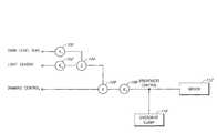
- FIG. 1is a block diagram of one embodiment of a brightness control circuit with ambient light correction.
- a user input(DIMMING CONTROL) is multiplied by a sum of a dark level bias (DARK LEVEL BIAS) and a light sensor output (LIGHT SENSOR) to produce a brightness control signal (BRIGHTNESS CONTROL) for a display driver 112 .
- the dark level bias and the light sensor outputare adjusted by respective scalar circuits (k 1 , k 2 ) 100 , 102 before being added by a summing circuit 104 .
- An output of the summing circuit 104 and the user inputis provided to a multiplier circuit 106 .
- An output of the multiplier circuit 106can be adjusted by a third scalar circuit (k 3 ) 108 to produce the brightness control signal.
- An overdrive clamp circuit 110is coupled to the brightness control signal to limit its amplitude range at the input of the display driver 112 .
- the display driver 112can be an inverter for fluorescent lamps or a LED driver that controls backlight illumination of LCDs in portable electronic devices (e.g., notebook computers, cell phones, etc.), automotive displays, electronic dashboards, television, and the like.
- the brightness control circuit with ambient light correctionprovides closed-loop adjustment of backlight brightness due to ambient light variations to maintain a desired LCD brightness as perceived by the human eye.
- the brightness control circuitadvantageously reduces the backlight brightness under low ambient light conditions to improve efficiency.
- a visible light sensordetects the ambient light level and generates the corresponding light sensor output.
- the user inputcan come from processors in LCD devices.
- the brightness control circuit with ambient light correctionadvantageously operates independently of the processors in the LCD devices.
- the display driver 112can also be used to control display brightness in CRT displays, plasma displays, OLED displays, and other visual information display systems that do not use backlight for display illumination.
- FIG. 2is a block diagram of another embodiment of a brightness control circuit with ambient light correction.
- a light sensor output(LIGHT SENSOR) is adjusted by a scalar circuit (k 2 ) 102 and then provided to a multiplier circuit 106 .
- a user input(DIMMING CONTROL) is also provided to the multiplier circuit 106 .
- the multiplier circuit 106outputs a signal that is the product of the user input and scaled light sensor output.
- a summing circuit 104adds the product to a dark level bias (DARK LEVEL BIAS) that has been adjusted by scalar circuit (k 1 ) 100 .
- DARK LEVEL BIASdark level bias
- An output of the summing circuit 104is adjusted by scalar circuit (k 3 ) 108 to generate a brightness control signal (BRIGHTNESS CONTROL) for a display driver 112 .
- An overdrive clamp 110is coupled to the brightness control signal to limit its amplitude range at the input of the display driver 112 .
- the brightness control circuits shown in both FIGS. 1 and 2automatically adjust the level of the brightness control signal in response to varying ambient light.
- the configuration of FIG. 2provides a predefined level of brightness in substantially total ambient darkness and independent of the user input.
- the output of the multiplier circuit 106in both FIGS. 1 and 2 , is substantially zero if the user input is about zero.
- the multiplier circuit 106can be implemented using software algorithm or analog/mixed-signal circuitry.
- the scaled dark level biasis added to the output of the multiplier circuit 106 to provide the predefined level of brightness in this case. This feature may be desired to prevent a user from using the brightness control circuit to turn off a visual information display system.
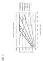
- FIG. 3illustrates brightness control signals as a function of ambient light levels for different user settings in accordance with the brightness control circuit of FIG. 1 .
- ambient light levelsare indicated in units of lux (or lumens/square meter) on a horizontal axis (or x-axis) in increasing order.
- Brightness control signal levelsare indicated as a percentage of a predefined (or full-scale) level on a vertical axis (or y-axis).
- Graph 300shows a first brightness control signal as a function of ambient light level given a first user setting (e.g., 100% duty cycle PWM dimming input).
- Graph 302shows a second brightness control signal as a function of ambient light level given a second user setting (e.g., 80% duty cycle PWM dimming input).
- Graph 304shows a third brightness control signal as a function of ambient light level given a third user setting (e.g., 60% duty cycle PWM dimming input).
- Graph 306shows a fourth brightness control signal as a function of ambient light level given a fourth user setting (e.g., 40% duty cycle PWM dimming input).
- Graph 308shows a fifth brightness control signal as a function of ambient light level given a fifth user setting (e.g., 20% duty cycle PWM dimming input).
- graph 310shows a sixth brightness control signal as a function of ambient light level given a sixth user setting (e.g., 0% duty cycle PWM dimming input).
- Graph 310lies substantially on top of the horizontal axis in accordance with the sixth user setting corresponding to turning off the visual information display system.
- the brightness control signalincreases (or decreases) with increasing (or decreasing) ambient light levels.
- the rate of increase (or decrease)depends on the user setting. For example, higher user settings cause the associated brightness control signals to increase faster as a function of ambient light level.
- the brightness control signal near zero luxis a function of a dark bias level and also depends on the user setting.
- the brightness control signalinitially increases linearly with increasing ambient light level and reaches saturation (or 100% of full-scale) after a predetermined ambient light level.
- the saturation pointis different for each user setting.
- the brightness control signalbegins to saturate at about 200 lux for the first user setting, at about 250 lux for the second user setting, and at about 350 lux for the third user setting.
- the brightness control circuitcan be designed for different saturation points and dark bias levels.
- FIG. 4is a schematic diagram of one embodiment of a brightness control circuit with a multiplier circuit to combine a light sensor output with a user adjustable PWM logic signal (PWM INPUT).
- PWM INPUTuser adjustable PWM logic signal
- the user adjustable PWM logic signalvaries in duty cycle from 0% for minimum user-defined brightness to 100% for maximum user-defined brightness.
- a microprocessorcan generate the user adjustable PWM logic signal based on user input which can be adjusted in response to various levels of eye fatigue for optimal viewing comfort.
- the user adjustable PWM logic signalis provided to an input buffer circuit 410 .
- the brightness control circuitincludes a visible light sensor 402 , a pair of current-steering diodes 404 , a network of resistors (R 1 , R 2 , R 3 , R 4 ) 412 , 420 , 416 , 418 , a filter capacitor (C 1 ) 414 , and an optional smoothing capacitor (C 2 ) 422 .
- the brightness control circuitselectively operates in a manual mode or an auto mode.
- the manual modeexcludes the visible light sensor 402
- the auto modeincludes the visible light sensor 402 for automatic adjustment of display brightness as ambient light changes.
- An enable signalselects between the two modes.
- the enable signalis provided to a buffer circuit 400 .
- An output of the buffer circuit 400is coupled to an input (A) of the visible light sensor 402 .
- the output of the buffer circuit 400is also provided to a gate terminal of a metal-oxide-semiconductor field-effect-transistor (MOSFET) switch 428 .
- the MOSFET switch 428is an n-type transistor with a source terminal coupled to ground and a drain terminal coupled to a first terminal of the second resistor (R 2 ) 420 .
- the pair of current-steering diodes 404includes a first diode 406 and a second diode 408 with commonly connected anodes that are coupled to an output (B) of the visible light sensor 402 .
- the first resistor (R 1 ) 412is coupled between the respective cathodes of the first diode 406 and the second diode 408 .
- An output of the input buffer circuit 410is coupled to the cathode of the first diode 406 .
- the filter capacitor 414is coupled between the cathode of the second diode 408 and ground.
- a second terminal of the second resistor 420is coupled to the cathode of the second diode 408 .
- the optional smoothing capacitor 422is coupled across the second resistor 420 .
- the third and fourth resistors 416 , 418are connected in series between the cathode of the second diode 408 and ground.
- the commonly connected terminals of the third and fourth resistors 416 , 418provide a brightness control signal to an input (BRITE) of a display driver (e.g., a backlight driver) 424 .
- the display driver 424delivers power to one or more light sources (e.g., fluorescent lamps) 426 coupled across its outputs.
- the enable signalis logic high and the buffer circuit 400 also outputs logic high (or VCC) to turn on the visible light sensor 402 and the MOSFET switch 428 .
- the visible light sensor 402outputs a sensor current signal in proportion to sensed ambient light level.
- the sensor current signal and the user adjustable PWM logic signalare multiplied using the pair of current-steering diodes 404 . For example, when the user adjustable PWM logic signal is high, the sensor current signal flows through the second diode 408 towards the brightness control signal (or output). When the user adjustable PWM logic signal is low, the sensor current signal flows through the first diode 406 away from the output or into the input buffer circuit 410 .
- the equation for the brightness control signal (BCS 1 ) in the auto modeis:
- BCS ⁇ ⁇ 1dutycycle ⁇ [ ( VCC ⁇ R ⁇ ⁇ 2 ⁇ R ⁇ ⁇ 4 [ ( R ⁇ ⁇ 1 + R ⁇ ⁇ 2 ) ⁇ ( R ⁇ ⁇ 3 + R ⁇ ⁇ 4 ) ] + ( R ⁇ ⁇ 1 ⁇ R ⁇ ⁇ 2 ) ) + ( ISRC ⁇ R ⁇ ⁇ 1 ⁇ R ⁇ ⁇ 2 ⁇ R ⁇ ⁇ 4 [ ( R ⁇ ⁇ 1 + R ⁇ ⁇ 2 ) ⁇ ( R ⁇ ⁇ 3 + R ⁇ ⁇ 4 ) ] + ( R ⁇ ⁇ 1 ⁇ R ⁇ ⁇ 2 ) ] .
- the term “dutycycle”corresponds to the duty cycle of the user adjustable PWM logic signal.
- the term “VCC”corresponds to the logic high output from the input buffer circuit 410 .
- the term “ISRC”corresponds to the sensor current signal.
- the first major term within the bracketscorresponds to a scaled dark bias level of the brightness control signal in total ambient darkness.
- the second major term within the bracketsintroduces the effect of the visible light sensor 402 .
- the network of resistors 412 , 420 416 , 418helps to provide the dark bias level and to scale the product of the sensor current signal and the user adjustable PWM logic signal.
- the first resistor 412serves to direct some current from the input buffer circuit 410 to the output in total ambient darkness.
- the second, third, and fourth resistors 420 , 416 , 418provide attenuation to scale the brightness control signal to be compatible with the operating range of the display driver 424 .
- the filter capacitor 414 and the optional smoothing capacitor 422slow down the response time of the backlight brightness control circuit to reduce flicker typically associated with indoor lighting sources.
- the brightness control signalclamps when the voltage at the cathode of the second diode 408 approaches the compliance voltage of the visible light sensor 402 plus a small voltage drop across the second diode 408 .
- the enable signalis logic low. Consequently, the visible light sensor 402 and the MOSFET switch 428 are off
- the pair of current-steering diodes 404isolates the visible light sensor 402 from the rest of the circuit.
- the off-state of the MOSFET switch 428removes the influence of the second resistor 420 and the optional smoothing capacitor 422 .
- the equation for the brightness control signal (BCS 2 ) in the manual modeis:
- BCS ⁇ ⁇ 2VCC ⁇ dutycycle ⁇ ⁇ R ⁇ ⁇ 4 ( R ⁇ ⁇ 1 + R ⁇ ⁇ 3 + R ⁇ ⁇ 4 ) .
- the filter capacitor 414filters the user adjustable PWM logic signal.
- the brightness control circuithas an option of having two filter time constants, one for the manual mode and one for the auto mode.
- the time constant for the manual modeis determined by the filter capacitor 414 in combination with the first, third and fourth resistors 412 , 416 , 418 .
- the node impedance presented to the filter capacitor 414is typically high during the manual mode.
- the time constant for the auto modecan be determined by the optional smoothing capacitor 422 , which is typically larger in value, to slow down the response of the visible light sensor 402 .
- the node impedance presented to the optional smoothing capacitor 422is typically low.
- the optional smoothing capacitor 422may be eliminated if the visible light sensor 402 is independently bandwidth limited.
- FIG. 5illustrates one embodiment of an ambient light sensor.
- the ambient light sensorincludes a light detector 500 , a first transistor 502 , a second transistor 504 and an additional current amplifier circuit 506 .
- the light detector 500generates an initial current in response to sensed ambient light.
- the first transistor 502 and the second transistor 504are configured as current mirrors to respectively conduct and duplicate the initial current.
- the second transistor 504can also provide amplification of the duplicated initial current.
- the additional current amplifier circuit 506provides further amplification of the current conducted by the second transistor 504 to generate a sensor current signal at an output of the ambient light sensor.
- the light detector 500is coupled between an input (or power) terminal (VDD) and a drain terminal of the first transistor 502 .
- the first transistor 502is an n-type MOSFET connected in a diode configuration with a source terminal coupled to ground.
- the first transistor 502conducts the initial current generated by the light detector 500 .
- the second transistor 504is also an n-type MOSFET with a source terminal coupled to ground. Gate terminals of the first and second transistors 502 , 504 are commonly connected.
- the second transistor 504conducts a second current that follows the initial current and is scaled by the geometric ratios between the first and second transistors 502 , 504 .
- the additional current amplifier circuit 506is coupled to a drain terminal of the second transistor 504 to provide amplification (e.g., by additional current mirror circuits) of the second current.
- the output of the additional current amplifier circuit 506i.e., the sensor current signal
- FIG. 6illustrates one embodiment of an ambient light sensor with an adjustable response time.
- the ambient light sensor of FIG. 6is substantially similar to the ambient light sensor of FIG. 5 and further includes a program capacitor 508 and source degeneration resistors 510 , 512 .
- the source degeneration resistors 510 , 512are inserted between ground and the respective source terminals of the first and second transistors 502 , 504 .
- the program capacitor 508is coupled between the source terminal of the first transistor 502 and ground.
- the program capacitor 508filters the initial current generated by the light detector 500 and advantageously provides the ability to adjust the response time of the ambient light sensor (e.g., by changing the value of the program capacitor 508 ).
- a closed loop systemsuch as automatic brightness control for a computer display or television
- a relatively slower response by the ambient light sensorallows the automatic brightness control to transition between levels slowly so that changes are not distracting to the viewer.
- the response time of the ambient light sensorcan also be slowed down by other circuitry downstream of the ambient light sensor, such as the optional smoothing capacitor 422 in the brightness control circuit of FIG. 4 .
- the brightness control circuit of FIG. 4has two filter time constants, one for the manual mode in which the visible light sensor 402 is not used and another for the auto mode which uses the visible light sensor 402 .
- the optional smoothing capacitor 422is included in the auto mode to slow down the response time of the brightness control circuit to accommodate the visible light sensor 402 .
- the optional smoothing capacitor 422may have an unintentional side effect of slowing down the response time of the brightness control circuit to the user adjustable PWM logic signal. This unintentional side effect is eliminated by using the program capacitor 508 to separately and independently slow down the response time of the ambient light sensor to a desired level.
- the optional smoothing capacitor 422can be eliminated from the brightness control circuit which then has one filter time constant for both the auto and manual modes.
- the program capacitor 508can be coupled to different nodes in the ambient light sensor to slow down response time. However, it is advantageous to filter (or limit the bandwidth of) the initial current rather than an amplified version of the initial current because the size and value of the program capacitor 508 can be smaller and lower, therefore more cost-efficient.
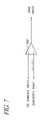
- FIG. 7illustrates conversion of a DC signal (DC DIMMING INPUT) to a PWM logic signal (PWM INPUT).
- the DC signal(or DC dimming interface) is used in some backlight systems to indicate user dimming preference.
- a comparator 700can be used to convert the DC signal to the PWM logic signal used in the brightness control circuit of FIG. 4 .
- the DC signalis provided to a non-inverting input of the comparator 700 .
- a periodic saw-tooth signal(SAWTOOTH RAMP) is provided to an inverting input of the comparator 700 .
- the periodic saw-tooth signalcan be generated using a C 555 timer (not shown).
- the comparator 700outputs a PWM signal with a duty cycle determined by the level of the DC signal. Other configurations to convert the DC signal to the PWM logic signal are also possible.
- FIG. 8is a schematic diagram of one embodiment of a brightness control circuit with a multiplier circuit to combine a light sensor output with a user adjustable potentiometer (R 3 ) 812 .
- Some display systemsuse the potentiometer 812 for user dimming control.
- the brightness control circuitconfigures a visible light sensor 802 to drive the potentiometer 812 with a current signal proportional to ambient light to generate a brightness control signal (BRIGHTNESS CONTROL) at its output.
- the potentiometer 812has a first terminal coupled to ground and a second terminal coupled to a supply voltage (VCC) via a first resistor (R 1 ) 810 .
- a second resistor (R 2 ) 808 in series with a p-type MOSFET switch 806are coupled in parallel with the first resistor 810 .
- the second terminal of the potentiometer 812is also coupled to an output of visible light sensor 802 via an isolation diode 804 .
- the isolation diode 804has an anode coupled to the output of the visible light sensor 802 and a cathode coupled to the second terminal of the potentiometer 812 .
- a fourth resistor (R 4 ) 814is coupled between the second terminal of the potentiometer 812 and the output of the brightness control circuit.
- a capacitor (Cout) 816is coupled between the output of the brightness control circuit and ground.
- the brightness control circuit of FIG. 8selectively operates in an auto mode or a manual mode.
- An enable signalindicates the selection of operating mode.
- the enable signalis provided to a buffer circuit 800 , and an output of the buffer circuit 800 is coupled to an input of the visible light sensor 802 and a gate terminal of the p-type MOSFET switch 806 .
- the buffer circuit 800turns on the visible light sensor 802 and disables (or turns off) the p-type MOSFET switch 806 . Turning off the p-type MOSFET switch 806 effectively removes the second resistor 808 from the circuit.
- the equation for the brightness control signal (BCS 3 ) at the output of the brightness control circuit during auto mode operationis:
- BCS ⁇ ⁇ 3[ VCC ⁇ ⁇ R ⁇ ⁇ 3 ( R ⁇ ⁇ 1 + R ⁇ ⁇ 3 ) ] + [ ISRC ⁇ ( R ⁇ ⁇ 1 ⁇ R ⁇ ⁇ 3 ) ( R ⁇ ⁇ 1 + R ⁇ ⁇ 3 ) ] .
- the first major term in brackets of the above equationcorresponds to the brightness control signal in total ambient darkness.
- the second major term in bracketsintroduces the effect of the visible light sensor 802 .
- the maximum range for the brightness control signal in the auto modeis determined by the compliance voltage of the visible light sensor 802 .
- the enable signalis logic low to indicate operation in the manual mode, and the buffer circuit 800 turns off the visible light sensor 802 and turns on the p-type MOSFET switch 806 . Turning on the p-type MOSFET switch 806 effectively couples the second resistor 808 in parallel with the first resistor 810 .
- the equation for the brightness control signal (BCS 4 ) at the output of the brightness control circuit during manual mode operationis:
- BCS ⁇ ⁇ 4VCC ⁇ R ⁇ ⁇ 3 ⁇ ( R ⁇ ⁇ 1 + R ⁇ ⁇ 2 ) ( R ⁇ ⁇ 1 ⁇ R ⁇ ⁇ 2 ) + ( R ⁇ ⁇ 1 ⁇ R ⁇ ⁇ 3 ) + ( R ⁇ ⁇ 2 ⁇ R ⁇ ⁇ 3 ) .
- FIG. 9is a schematic diagram of one embodiment of a brightness control circuit with a multiplier circuit to combine a light sensor output with a user adjustable digital word.
- Some display systemsuse a DAC 918 for dimming control.
- a binary input(bn . . . b 1 ) is used to indicate user dimming preference.
- the DAC 918generates an analog voltage (Vout) corresponding to the binary input.
- the analog voltageis the brightness control signal at an output of the brightness control circuit.
- a voltage clamp circuit 920is coupled to the output brightness control circuit to limit the range of the brightness control signal.
- the value of the analog voltagealso depends on a reference voltage (Vref) of the DAC 918 .
- the reference voltageis generated using a sensor current signal from a visible light sensor 902 that senses ambient light.
- the visible light sensor 902drives a network of resistors (R 1 , R 2 , R 3 ) 906 , 902 , 912 through an isolation diode 904 .
- An output of the visible light sensor 902is coupled to an anode of the isolation diode 904 .
- the first resistor (R 1 ) 906is coupled between a supply voltage (VCC) and a cathode of the isolation diode 904 .
- the second resistor (R 2 ) 908is coupled in series with a semiconductor switch 910 between the cathode of the isolation diode 904 and ground.
- the third resistor (R 3 ) 912is coupled between the cathode of the isolation diode 904 and ground.
- An optional capacitor 914is coupled in parallel with the third resistor 912 to provide filtering.
- An optional buffer circuit 916is coupled between the cathode of the isolation diode 904 and the reference voltage input of the DAC 918 .
- the brightness control circuit of FIG. 9can be configured for manual mode operation with the visible light sensor 902 disabled or for auto mode operation with the visible light sensor 902 enabled.
- An enable signal (AUTO)is provided to a buffer circuit 900 to make the selection between auto and manual modes.
- An output of the buffer circuit 900is provided to an input of the visible light sensor 902 and to a gate terminal of the semiconductor switch 910 .
- the visible light sensor 902When the enable signal is logic high to select auto mode operation, the visible light sensor 902 is active and the semiconductor switch 910 is on to effectively couple the second resistor 908 in parallel with the third resistor 912 .
- the equation for the brightness control signal (BCS 5 ) at the output of the DAC 918is:
- BCS ⁇ ⁇ 5binary ⁇ ⁇ % ⁇ ⁇ fullscale ⁇ [ ( [ VCC ⁇ ( R ⁇ ⁇ 2 ⁇ R ⁇ ⁇ 3 ) ] + [ ISRC ⁇ R ⁇ ⁇ 1 ⁇ R ⁇ ⁇ 2 ⁇ R ⁇ ⁇ 3 ] ( R ⁇ ⁇ 1 ⁇ R ⁇ ⁇ 2 ) + ( R ⁇ ⁇ 1 ⁇ R ⁇ ⁇ 3 ) + ( R ⁇ ⁇ 2 ⁇ R ⁇ ⁇ 3 ) ] ] .
- the visible light sensor 902When the enable signal is logic low to select manual mode operation, the visible light sensor 902 is disabled and the semiconductor switch 910 is off to effectively remove the second resistor 908 from the circuit.
- the equation for the brightness control signal (BCS 6 ) at the output of the DAC 918is:
- BCS ⁇ ⁇ 6binary ⁇ ⁇ % ⁇ ⁇ fullscale ⁇ VCC ⁇ R ⁇ ⁇ 3 ( R ⁇ ⁇ 1 + R ⁇ ⁇ 3 ) .
- FIG. 10is a schematic diagram of one embodiment of a brightness control circuit with automatic shut down when ambient light is above a predetermined threshold.
- auxiliary light sourcese.g., backlight or frontlight
- the brightness control circuit of FIG. 10includes a shut down signal (SHUT OFF) to disable the backlight or the frontlight when the ambient light level is above the predetermined threshold.
- SHUT OFFshut down signal
- the brightness control circuit of FIG. 10advantageously uses a visible light sensor 1000 with two current source outputs that produce currents that are proportional to the sensed ambient light.
- the two current source outputsinclude a sourcing current (SRC) and a sinking current (SNK).
- the sourcing currentis used to generate the brightness control signal.
- the portion of the circuit generating the brightness control signalis substantially similar to the brightness control circuit shown in FIG. 4 and is not further discussed.
- the sinking currentis used to generate the shut down signal.
- a comparator 1014generates the shut down signal.
- a resistor (R 6 ) 1002is coupled between a selective supply voltage and the sinking current output of the visible light sensor 1000 to generate a comparison voltage for an inverting input of the comparator 1014 .
- a low pass filter capacitor (C 3 ) 1004is coupled in parallel with the resistor 1002 to slow down the reaction time of the sinking current output to avoid triggering on 60 hertz light fluctuations.
- a resistor (R 7 ) 1006coupled in series with a resistor (R 8 ) 1012 between the selective supply voltage and ground generates a threshold voltage for a non-inverting input of the comparator 1014 .
- a feedback resistor (R 9 ) coupled between an output of the comparator 1014 and the non-inverting input of the comparator 1014provides hysteresis for the comparator 1014 .
- a pull-up resistor (R 10 )is coupled between the selective supply voltage and the output of the comparator 1014 .
- the selective supply voltagemay be provided by the output of the buffer circuit 400 which also enables the visible light sensor 1000 .
- the sinking currentWhen the ambient level is relatively low, the sinking current is relatively small and the voltage drop across the resistor 1002 conducting the sinking current is correspondingly small.
- the comparison voltage at the inverting input of the comparator 1014is greater than the threshold voltage at the non-inverting input of the comparator, and the output of the comparator 1014 is low.
- the ambient levelis relatively high, the sinking current is relatively large and the voltage drop across the resistor 1002 is also large.
- the comparison voltage at the inverting input of the comparator 1014becomes less than the threshold voltage and the comparator 1014 outputs logic high to activate the shut down signal.
- Other configurationsmay be used to generate the shut down signal based on the sensed ambient light level.
Landscapes
- Engineering & Computer Science (AREA)
- Physics & Mathematics (AREA)
- Computer Hardware Design (AREA)
- General Physics & Mathematics (AREA)
- Theoretical Computer Science (AREA)
- Liquid Crystal (AREA)
- Liquid Crystal Display Device Control (AREA)
- Circuit Arrangement For Electric Light Sources In General (AREA)
Abstract
Description
Claims (20)
Priority Applications (1)
| Application Number | Priority Date | Filing Date | Title |
|---|---|---|---|
| US12/336,990US8223117B2 (en) | 2004-02-09 | 2008-12-17 | Method and apparatus to control display brightness with ambient light correction |
Applications Claiming Priority (3)
| Application Number | Priority Date | Filing Date | Title |
|---|---|---|---|
| US54309404P | 2004-02-09 | 2004-02-09 | |
| US11/023,295US7468722B2 (en) | 2004-02-09 | 2004-12-27 | Method and apparatus to control display brightness with ambient light correction |
| US12/336,990US8223117B2 (en) | 2004-02-09 | 2008-12-17 | Method and apparatus to control display brightness with ambient light correction |
Related Parent Applications (1)
| Application Number | Title | Priority Date | Filing Date |
|---|---|---|---|
| US11/023,295ContinuationUS7468722B2 (en) | 2004-02-09 | 2004-12-27 | Method and apparatus to control display brightness with ambient light correction |
Publications (2)
| Publication Number | Publication Date |
|---|---|
| US20090091560A1 US20090091560A1 (en) | 2009-04-09 |
| US8223117B2true US8223117B2 (en) | 2012-07-17 |
Family
ID=34889643
Family Applications (2)
| Application Number | Title | Priority Date | Filing Date |
|---|---|---|---|
| US11/023,295Active - Reinstated2026-06-02US7468722B2 (en) | 2004-02-09 | 2004-12-27 | Method and apparatus to control display brightness with ambient light correction |
| US12/336,990Active2027-04-17US8223117B2 (en) | 2004-02-09 | 2008-12-17 | Method and apparatus to control display brightness with ambient light correction |
Family Applications Before (1)
| Application Number | Title | Priority Date | Filing Date |
|---|---|---|---|
| US11/023,295Active - Reinstated2026-06-02US7468722B2 (en) | 2004-02-09 | 2004-12-27 | Method and apparatus to control display brightness with ambient light correction |
Country Status (1)
| Country | Link |
|---|---|
| US (2) | US7468722B2 (en) |
Cited By (10)
| Publication number | Priority date | Publication date | Assignee | Title |
|---|---|---|---|---|
| US20110175950A1 (en)* | 2008-10-06 | 2011-07-21 | Sharp Kabushiki Kaisha | Illuminating apparatus and liquid crystal display apparatus provided with the same |
| US20120162245A1 (en)* | 2010-12-22 | 2012-06-28 | Louis Joseph Kerofsky | Ambient adaptive illumination of a liquid crystal display |
| US9129548B2 (en) | 2012-11-15 | 2015-09-08 | Apple Inc. | Ambient light sensors with infrared compensation |
| CN105845102A (en)* | 2016-05-19 | 2016-08-10 | 合肥惠科金扬科技有限公司 | Environment-based screen brightness adjusting circuit and display screen |
| US11211032B2 (en) | 2019-11-27 | 2021-12-28 | Samsung Electronics Co., Ltd. | Electronic device for supporting to control auto brightness of display |
| US11250791B2 (en)* | 2020-01-03 | 2022-02-15 | Beijing Xiaomi Mobile Software Co., Ltd. | Method and device for detecting ambient light, and storage medium |
| US20230130976A1 (en)* | 2021-10-25 | 2023-04-27 | Lg Electronics Inc. | Image display device and method for controlling the same |
| US11705062B1 (en)* | 2022-10-13 | 2023-07-18 | Motorola Mobility Llc | Methods of display brightness control and corresponding electronic devices |
| US11811990B2 (en)* | 2021-11-12 | 2023-11-07 | Seiko Epson Corporation | Multi-feed detection device, transport device, and image reading device |
| US12028658B2 (en) | 2021-08-03 | 2024-07-02 | Samsung Electronics Co., Ltd. | Content creative intention preservation under various ambient color temperatures |
Families Citing this family (137)
| Publication number | Priority date | Publication date | Assignee | Title |
|---|---|---|---|---|
| US8493370B2 (en)* | 2001-08-29 | 2013-07-23 | Palm, Inc. | Dynamic brightness range for portable computer displays based on ambient conditions |
| US7894177B2 (en)* | 2005-12-29 | 2011-02-22 | Apple Inc. | Light activated hold switch |
| US20070171157A1 (en)* | 2003-10-15 | 2007-07-26 | Samsung Electronics Co., Ltd | Display apparatus having photo sensor |
| US7468722B2 (en)* | 2004-02-09 | 2008-12-23 | Microsemi Corporation | Method and apparatus to control display brightness with ambient light correction |
| JP3968587B2 (en)* | 2004-03-30 | 2007-08-29 | 船井電機株式会社 | Liquid crystal television, backlight control device, and backlight control method |
| US8381135B2 (en) | 2004-07-30 | 2013-02-19 | Apple Inc. | Proximity detector in handheld device |
| US8004511B2 (en) | 2004-12-02 | 2011-08-23 | Sharp Laboratories Of America, Inc. | Systems and methods for distortion-related source light management |
| US7782405B2 (en) | 2004-12-02 | 2010-08-24 | Sharp Laboratories Of America, Inc. | Systems and methods for selecting a display source light illumination level |
| US7982707B2 (en) | 2004-12-02 | 2011-07-19 | Sharp Laboratories Of America, Inc. | Methods and systems for generating and applying image tone scale adjustments |
| US8120570B2 (en)* | 2004-12-02 | 2012-02-21 | Sharp Laboratories Of America, Inc. | Systems and methods for tone curve generation, selection and application |
| US7515160B2 (en)* | 2006-07-28 | 2009-04-07 | Sharp Laboratories Of America, Inc. | Systems and methods for color preservation with image tone scale corrections |
| US7768496B2 (en) | 2004-12-02 | 2010-08-03 | Sharp Laboratories Of America, Inc. | Methods and systems for image tonescale adjustment to compensate for a reduced source light power level |
| US8922594B2 (en) | 2005-06-15 | 2014-12-30 | Sharp Laboratories Of America, Inc. | Methods and systems for enhancing display characteristics with high frequency contrast enhancement |
| US7800577B2 (en) | 2004-12-02 | 2010-09-21 | Sharp Laboratories Of America, Inc. | Methods and systems for enhancing display characteristics |
| US8913089B2 (en) | 2005-06-15 | 2014-12-16 | Sharp Laboratories Of America, Inc. | Methods and systems for enhancing display characteristics with frequency-specific gain |
| US9083969B2 (en)* | 2005-08-12 | 2015-07-14 | Sharp Laboratories Of America, Inc. | Methods and systems for independent view adjustment in multiple-view displays |
| US8111265B2 (en) | 2004-12-02 | 2012-02-07 | Sharp Laboratories Of America, Inc. | Systems and methods for brightness preservation using a smoothed gain image |
| US7924261B2 (en) | 2004-12-02 | 2011-04-12 | Sharp Laboratories Of America, Inc. | Methods and systems for determining a display light source adjustment |
| US8947465B2 (en) | 2004-12-02 | 2015-02-03 | Sharp Laboratories Of America, Inc. | Methods and systems for display-mode-dependent brightness preservation |
| US7961199B2 (en) | 2004-12-02 | 2011-06-14 | Sharp Laboratories Of America, Inc. | Methods and systems for image-specific tone scale adjustment and light-source control |
| JP4819353B2 (en)* | 2004-12-20 | 2011-11-24 | Necディスプレイソリューションズ株式会社 | Display device |
| JP2006208595A (en)* | 2005-01-26 | 2006-08-10 | Brother Ind Ltd | Liquid crystal display device and electronic device |
| US7539513B2 (en) | 2005-02-02 | 2009-05-26 | National Telephone Products, Inc. | Portable phone with ergonomic image projection system |
| US7375473B2 (en)* | 2005-04-15 | 2008-05-20 | Eastman Kodak Company | Variable power control for OLED area illumination |
| CN102394049B (en)* | 2005-05-02 | 2015-04-15 | 株式会社半导体能源研究所 | Driving method of display device |
| US8059109B2 (en)* | 2005-05-20 | 2011-11-15 | Semiconductor Energy Laboratory Co., Ltd. | Display device and electronic apparatus |
| US7636078B2 (en)* | 2005-05-20 | 2009-12-22 | Semiconductor Energy Laboratory Co., Ltd. | Display device and electronic device |
| EP1724751B1 (en)* | 2005-05-20 | 2013-04-10 | Semiconductor Energy Laboratory Co., Ltd. | Liquid crystal display device and electronic apparatus |
| TW200704109A (en)* | 2005-07-01 | 2007-01-16 | Inventec Appliances Corp | System for automatically adjusting screen displaying effect based on environmental brightness |
| JP4039440B2 (en)* | 2005-09-29 | 2008-01-30 | エプソンイメージングデバイス株式会社 | Liquid crystal device, electro-optical device and electronic apparatus |
| US7714265B2 (en) | 2005-09-30 | 2010-05-11 | Apple Inc. | Integrated proximity sensor and light sensor |
| US7633076B2 (en) | 2005-09-30 | 2009-12-15 | Apple Inc. | Automated response to and sensing of user activity in portable devices |
| US7728316B2 (en)* | 2005-09-30 | 2010-06-01 | Apple Inc. | Integrated proximity sensor and light sensor |
| US7701434B2 (en)* | 2005-10-31 | 2010-04-20 | Research In Motion Limited | Automatic screen and keypad brightness adjustment on a mobile handheld electronic device |
| US20070120807A1 (en)* | 2005-11-28 | 2007-05-31 | Shwang-Shi Bai | Display system with high motion picture quality and luminance control thereof |
| TWI307488B (en)* | 2005-12-05 | 2009-03-11 | Benq Corp | Method for adjusting monitor luminance |
| KR101159354B1 (en)* | 2005-12-08 | 2012-06-25 | 엘지디스플레이 주식회사 | Apparatus and method for driving inverter, and image display apparatus using the same |
| KR100755624B1 (en)* | 2006-02-09 | 2007-09-04 | 삼성전기주식회사 | LCD in field sequential color mode |
| JP5008017B2 (en)* | 2006-02-10 | 2012-08-22 | ソニーモバイルディスプレイ株式会社 | Display device |
| JP2007241358A (en)* | 2006-03-06 | 2007-09-20 | Hitachi Displays Ltd | Image display device |
| US7839406B2 (en) | 2006-03-08 | 2010-11-23 | Sharp Laboratories Of America, Inc. | Methods and systems for enhancing display characteristics with ambient illumination input |
| TW200737915A (en)* | 2006-03-17 | 2007-10-01 | Inventec Appliances Corp | Method for switching operation mode of mobile communication apparatus and mobile communication apparatus thereof |
| KR100748319B1 (en)* | 2006-03-29 | 2007-08-09 | 삼성에스디아이 주식회사 | OLED display device and driving method thereof |
| US7515822B2 (en)* | 2006-05-12 | 2009-04-07 | Microsoft Corporation | Imaging systems' direct illumination level adjusting method and system involves adjusting operation of image sensor of imaging system based on detected level of ambient illumination |
| US7825891B2 (en)* | 2006-06-02 | 2010-11-02 | Apple Inc. | Dynamic backlight control system |
| US9086737B2 (en) | 2006-06-15 | 2015-07-21 | Apple Inc. | Dynamically controlled keyboard |
| KR100764454B1 (en)* | 2006-06-20 | 2007-10-05 | 삼성전기주식회사 | LC backlight inverter |
| US20080002070A1 (en)* | 2006-06-29 | 2008-01-03 | Eastman Kodak Company | Driving oled display with improved uniformity |
| US20080042938A1 (en)* | 2006-08-15 | 2008-02-21 | Cok Ronald S | Driving method for el displays with improved uniformity |
| KR101242125B1 (en)* | 2006-08-29 | 2013-03-12 | 삼성디스플레이 주식회사 | Device of driving backlight assembly, display apparatus having the same and method of driving backlight assembly |
| WO2008029548A1 (en)* | 2006-09-06 | 2008-03-13 | Sharp Kabushiki Kaisha | Illuminating device, backlight device, liquid crystal display device, method for controlling illuminating device and method for controlling liquid crystal display device |
| KR101254735B1 (en)* | 2006-09-12 | 2013-04-16 | 삼성디스플레이 주식회사 | Brightness adjusting device and liquid crystal display |
| US7879631B2 (en)* | 2006-10-24 | 2011-02-01 | Hong Jim T | Systems and methods for on-die light sensing with low leakage |
| US8373355B2 (en)* | 2006-11-09 | 2013-02-12 | Apple Inc. | Brightness control of a status indicator light |
| JP4247269B2 (en) | 2006-11-21 | 2009-04-02 | 株式会社ルネサステクノロジ | Display device drive circuit |
| KR101318081B1 (en)* | 2006-11-21 | 2013-10-14 | 엘지디스플레이 주식회사 | LCD and drive method thereof |
| US8006002B2 (en) | 2006-12-12 | 2011-08-23 | Apple Inc. | Methods and systems for automatic configuration of peripherals |
| KR101359917B1 (en)* | 2006-12-15 | 2014-02-07 | 삼성디스플레이 주식회사 | Organic light emitting device |
| US8031164B2 (en)* | 2007-01-05 | 2011-10-04 | Apple Inc. | Backlight and ambient light sensor system |
| US8698727B2 (en)* | 2007-01-05 | 2014-04-15 | Apple Inc. | Backlight and ambient light sensor system |
| US7957762B2 (en)* | 2007-01-07 | 2011-06-07 | Apple Inc. | Using ambient light sensor to augment proximity sensor output |
| WO2008088892A2 (en)* | 2007-01-19 | 2008-07-24 | Pixtronix, Inc. | Sensor-based feedback for display apparatus |
| TW200832319A (en)* | 2007-01-26 | 2008-08-01 | Tpo Displays Corp | Display device and luminance control method |
| US7826681B2 (en) | 2007-02-28 | 2010-11-02 | Sharp Laboratories Of America, Inc. | Methods and systems for surround-specific display modeling |
| US8693877B2 (en)* | 2007-03-09 | 2014-04-08 | Apple Inc. | Integrated infrared receiver and emitter for multiple functionalities |
| US7968835B2 (en)* | 2007-04-27 | 2011-06-28 | Hewlett-Packard Development Company, L.P. | Electronic device having LED with variable brightness |
| JP5073741B2 (en)* | 2007-05-18 | 2012-11-14 | シャープ株式会社 | Display device |
| WO2008143211A1 (en)* | 2007-05-18 | 2008-11-27 | Sharp Kabushiki Kaisha | Display device |
| EP2148237B1 (en)* | 2007-05-18 | 2013-05-15 | Sharp Kabushiki Kaisha | Display device |
| US20080303918A1 (en)* | 2007-06-11 | 2008-12-11 | Micron Technology, Inc. | Color correcting for ambient light |
| US7868294B2 (en)* | 2007-11-15 | 2011-01-11 | Silicon Laboratories Inc. | Apparatus and method for display control using ambient light measurement signal from an infrared receiver |
| JP4357572B2 (en)* | 2008-02-28 | 2009-11-04 | 株式会社東芝 | Video display device and video display method |
| TW200939192A (en)* | 2008-03-11 | 2009-09-16 | Novatek Microelectronics Corp | LCD with the function of eliminating the power-off residual images |
| US8102375B1 (en)* | 2008-04-07 | 2012-01-24 | Crestron Electronics Inc. | Dimmable keypad device suitable for multiple faceplate and legend colors |
| US8610659B2 (en)* | 2008-05-12 | 2013-12-17 | Blackberry Limited | Method and apparatus for automatic brightness adjustment on a display of a mobile electronic device |
| CN101609650B (en)* | 2008-06-19 | 2011-12-07 | 群康科技(深圳)有限公司 | LCD and driving method thereof |
| US8416179B2 (en) | 2008-07-10 | 2013-04-09 | Sharp Laboratories Of America, Inc. | Methods and systems for color preservation with a color-modulated backlight |
| US20100045190A1 (en)* | 2008-08-20 | 2010-02-25 | White Electronic Designs Corporation | Led backlight |
| US9330630B2 (en) | 2008-08-30 | 2016-05-03 | Sharp Laboratories Of America, Inc. | Methods and systems for display source light management with rate change control |
| US8203524B2 (en)* | 2008-09-10 | 2012-06-19 | Sanyo Electric Co., Ltd. | Light-emitting element driving circuit |
| BRPI0920811A2 (en)* | 2008-10-08 | 2015-12-22 | Sharp Kk | lighting apparatus and liquid crystal display device fitted with the same |
| EP2326083B1 (en)* | 2008-10-15 | 2016-06-29 | Panasonic Intellectual Property Management Co., Ltd. | Brightness correction device and brightness correction method |
| KR100959105B1 (en)* | 2008-10-15 | 2010-05-25 | 삼성모바일디스플레이주식회사 | Organic light emitting display |
| EP2359170B1 (en)* | 2008-11-13 | 2016-02-17 | Koninklijke Philips N.V. | Device for adaptable wavelength conversion and a solar cell |
| KR101296564B1 (en)* | 2008-12-23 | 2013-08-13 | 엘지디스플레이 주식회사 | Liquid crystal display device |
| US8416302B2 (en)* | 2009-02-10 | 2013-04-09 | Microsoft Corporation | Low-light imaging augmented with non-intrusive lighting |
| CN201562445U (en)* | 2009-04-28 | 2010-08-25 | 鸿富锦精密工业(深圳)有限公司 | Electronic photo frame with intelligent control of display brightness |
| CN201562447U (en)* | 2009-04-28 | 2010-08-25 | 鸿富锦精密工业(深圳)有限公司 | Electronic photo frame with intelligent control of display brightness |
| US8107825B2 (en)* | 2009-05-08 | 2012-01-31 | Samsung Electronics Co., Ltd. | Apparatus and method for support of dimming in visible light communication |
| US8165724B2 (en) | 2009-06-17 | 2012-04-24 | Sharp Laboratories Of America, Inc. | Methods and systems for power-controlling display devices |
| US8138687B2 (en)* | 2009-06-30 | 2012-03-20 | Apple Inc. | Multicolor lighting system |
| JP4686644B2 (en)* | 2009-07-07 | 2011-05-25 | シャープ株式会社 | Liquid crystal display |
| US8502702B2 (en) | 2009-07-26 | 2013-08-06 | Aspen Avionics, Inc. | Electronic avionics systems and methods |
| US8643508B2 (en) | 2009-07-26 | 2014-02-04 | Aspen Avionics, Inc. | Avionics device, systems and methods of display |
| US8749594B2 (en)* | 2009-07-26 | 2014-06-10 | Aspen Avionics, Inc. | Avionics device display dimming system and method |
| US11150105B2 (en) | 2009-07-26 | 2021-10-19 | Aspen Avionics, Inc. | Avionics device, systems and methods of display |
| CN102035919B (en)* | 2009-09-28 | 2013-06-05 | 中兴通讯股份有限公司 | Method and device for controlling display brightness |
| TWI413096B (en)* | 2009-10-08 | 2013-10-21 | Chunghwa Picture Tubes Ltd | Adaptive frame rate modulation system and method thereof |
| US20110095875A1 (en)* | 2009-10-23 | 2011-04-28 | Broadcom Corporation | Adjustment of media delivery parameters based on automatically-learned user preferences |
| KR101631958B1 (en)* | 2010-01-14 | 2016-06-20 | 엘지전자 주식회사 | Input device and mobile terminal having the same |
| JP2011249895A (en)* | 2010-05-24 | 2011-12-08 | Panasonic Corp | Signal processing system and signal processing apparatus |
| US8400626B2 (en) | 2010-06-10 | 2013-03-19 | Apple Inc. | Ambient light sensor |
| US9119261B2 (en)* | 2010-07-26 | 2015-08-25 | Apple Inc. | Display brightness control temporal response |
| WO2012030622A1 (en)* | 2010-08-31 | 2012-03-08 | Dolby Laboratories Licensing Corporation | Ambient black level |
| US8860653B2 (en) | 2010-09-01 | 2014-10-14 | Apple Inc. | Ambient light sensing technique |
| US11454361B2 (en)* | 2010-10-21 | 2022-09-27 | Ole Falk Smed | Automatically adjusting task light |
| FR2971066B1 (en) | 2011-01-31 | 2013-08-23 | Nanotec Solution | THREE-DIMENSIONAL MAN-MACHINE INTERFACE. |
| US9391568B2 (en)* | 2011-05-16 | 2016-07-12 | Rosemount Inc. | Process device with light change triggered display |
| KR20120130842A (en)* | 2011-05-24 | 2012-12-04 | 삼성전자주식회사 | Hybrid display apparatus and display method thereof |
| US8749538B2 (en) | 2011-10-21 | 2014-06-10 | Qualcomm Mems Technologies, Inc. | Device and method of controlling brightness of a display based on ambient lighting conditions |
| CN103377625A (en)* | 2012-04-25 | 2013-10-30 | 鸿富锦精密工业(深圳)有限公司 | Power-saving control circuit |
| US9146304B2 (en) | 2012-09-10 | 2015-09-29 | Apple Inc. | Optical proximity sensor with ambient light and temperature compensation |
| CN102982769B (en)* | 2012-11-09 | 2015-09-09 | 广东欧珀移动通信有限公司 | A kind of method of Automatic adjusument screen appointed area brightness |
| US9183812B2 (en) | 2013-01-29 | 2015-11-10 | Pixtronix, Inc. | Ambient light aware display apparatus |
| FR3002052B1 (en) | 2013-02-14 | 2016-12-09 | Fogale Nanotech | METHOD AND DEVICE FOR NAVIGATING A DISPLAY SCREEN AND APPARATUS COMPRISING SUCH A NAVIGATION |
| TWM470959U (en)* | 2013-07-05 | 2014-01-21 | Micro Star Int Co Ltd | Display device |
| CN104332151B (en)* | 2013-11-06 | 2017-04-12 | 苹果公司 | Display device, display device circuit and method for operating display device |
| US9396684B2 (en) | 2013-11-06 | 2016-07-19 | Apple Inc. | Display with peak luminance control sensitive to brightness setting |
| US9633607B1 (en)* | 2013-12-02 | 2017-04-25 | Amazon Technologies, Inc. | Adaptive RGBW conversion |
| KR20150133941A (en)* | 2014-05-20 | 2015-12-01 | 삼성디스플레이 주식회사 | Power supply device and method for driving power supply device |
| US9478157B2 (en)* | 2014-11-17 | 2016-10-25 | Apple Inc. | Ambient light adaptive displays |
| US9530362B2 (en) | 2014-12-23 | 2016-12-27 | Apple Inc. | Ambient light adaptive displays with paper-like appearance |
| US9679534B2 (en) | 2015-02-13 | 2017-06-13 | Microsoft Technology Licensing, Llc | Emission unit brightness adjustment |
| US10089959B2 (en) | 2015-04-24 | 2018-10-02 | Apple Inc. | Display with continuous profile peak luminance control |
| KR102231046B1 (en)* | 2015-05-28 | 2021-03-23 | 엘지디스플레이 주식회사 | Display device and method for driving the same |
| CN106484354B (en)* | 2016-10-31 | 2019-12-20 | 维沃移动通信有限公司 | Display brightness adjusting method and mobile terminal |
| US10283057B2 (en)* | 2017-01-26 | 2019-05-07 | Dell Products L.P. | Heuristic learning for setting automatic display brightness based on an ambient light sensor |
| CN108877688A (en)* | 2017-05-12 | 2018-11-23 | 京东方科技集团股份有限公司 | Backlight brightness control method and device |
| CN107808640A (en)* | 2017-10-26 | 2018-03-16 | 惠科股份有限公司 | Display system and current driving method thereof |
| CN112543965B (en)* | 2018-08-02 | 2025-01-24 | ams有限公司 | Device and method for controlling display screen brightness |
| CN109343299B (en)* | 2018-11-23 | 2021-04-20 | 苏州佳世达光电有限公司 | Projector and brightness adjusting method |
| CN110271420A (en)* | 2019-06-28 | 2019-09-24 | 马瑞利汽车电子(广州)有限公司 | A kind of automobile instrument display brightness switching device |
| CN110503925A (en)* | 2019-09-02 | 2019-11-26 | 深圳利亚德光电有限公司 | Adjusting method, device, storage medium and the processor of the backlight illumination of display screen |
| US11835382B2 (en) | 2021-03-02 | 2023-12-05 | Apple Inc. | Handheld electronic device |
| US12355907B2 (en) | 2022-01-10 | 2025-07-08 | Apple Inc. | Handheld electronic device |
| JP2024072902A (en)* | 2022-11-17 | 2024-05-29 | シャープ株式会社 | Display device and display control method |
| CN115938318A (en)* | 2022-12-25 | 2023-04-07 | 宜宾市天珑通讯有限公司 | A dimming circuit according to sunlight intensity, electronic equipment and control method thereof |
Citations (338)
| Publication number | Priority date | Publication date | Assignee | Title |
|---|---|---|---|---|
| US2429162A (en) | 1943-01-18 | 1947-10-14 | Boucher And Keiser Company | Starting and operating of fluorescent lamps |
| US2440984A (en) | 1945-06-18 | 1948-05-04 | Gen Electric | Magnetic testing apparatus and method |
| US2572258A (en) | 1946-07-20 | 1951-10-23 | Picker X Ray Corp Waite Mfg | X-ray tube safety device |
| US2965799A (en) | 1957-09-26 | 1960-12-20 | Gen Electric | Fluorescent lamp ballast |
| US2968028A (en) | 1956-06-21 | 1961-01-10 | Fuje Tsushinki Seizo Kabushiki | Multi-signals controlled selecting systems |
| US3141112A (en) | 1962-08-20 | 1964-07-14 | Gen Electric | Ballast apparatus for starting and operating electric discharge lamps |
| US3449629A (en) | 1968-05-16 | 1969-06-10 | Westinghouse Electric Corp | Light,heat and temperature control systems |
| US3565806A (en) | 1965-11-23 | 1971-02-23 | Siemens Ag | Manganese zinc ferrite core with high initial permeability |
| US3597656A (en) | 1970-03-16 | 1971-08-03 | Rucker Co | Modulating ground fault detector and interrupter |
| US3611021A (en) | 1970-04-06 | 1971-10-05 | North Electric Co | Control circuit for providing regulated current to lamp load |
| US3683923A (en) | 1970-09-25 | 1972-08-15 | Valleylab Inc | Electrosurgery safety circuit |
| US3737755A (en) | 1972-03-22 | 1973-06-05 | Bell Telephone Labor Inc | Regulated dc to dc converter with regulated current source driving a nonregulated inverter |
| US3742330A (en) | 1971-09-07 | 1973-06-26 | Delta Electronic Control Corp | Current mode d c to a c converters |
| US3916283A (en) | 1975-02-10 | 1975-10-28 | Pylon Electronic Dev | DC to DC Converter |
| US3936696A (en) | 1973-08-27 | 1976-02-03 | Lutron Electronics Co., Inc. | Dimming circuit with saturated semiconductor device |
| US3944888A (en) | 1974-10-04 | 1976-03-16 | I-T-E Imperial Corporation | Selective tripping of two-pole ground fault interrupter |
| US4053813A (en) | 1976-03-01 | 1977-10-11 | General Electric Company | Discharge lamp ballast with resonant starting |
| US4060751A (en) | 1976-03-01 | 1977-11-29 | General Electric Company | Dual mode solid state inverter circuit for starting and ballasting gas discharge lamps |
| US4204141A (en) | 1978-09-11 | 1980-05-20 | Esquire, Inc. | Adjustable DC pulse circuit for variation over a predetermined range using two timer networks |
| US4277728A (en) | 1978-05-08 | 1981-07-07 | Stevens Luminoptics | Power supply for a high intensity discharge or fluorescent lamp |
| US4307441A (en) | 1980-07-28 | 1981-12-22 | United Technologies Corporation | Current balanced DC-to-DC converter |
| US4353009A (en) | 1980-12-19 | 1982-10-05 | Gte Products Corporation | Dimming circuit for an electronic ballast |
| US4386345A (en)* | 1981-09-22 | 1983-05-31 | Sperry Corporation | Color and brightness tracking in a cathode ray tube display system |
| US4388562A (en) | 1980-11-06 | 1983-06-14 | Astec Components, Ltd. | Electronic ballast circuit |
| US4392087A (en) | 1980-11-26 | 1983-07-05 | Honeywell, Inc. | Two-wire electronic dimming ballast for gaseous discharge lamps |
| US4437042A (en) | 1981-12-10 | 1984-03-13 | General Electric Company | Starting and operating circuit for gaseous discharge lamps |
| US4441054A (en) | 1982-04-12 | 1984-04-03 | Gte Products Corporation | Stabilized dimming circuit for lamp ballasts |
| US4463287A (en) | 1981-10-07 | 1984-07-31 | Cornell-Dubilier Corp. | Four lamp modular lighting control |
| US4469988A (en) | 1980-06-23 | 1984-09-04 | Cronin Donald L | Electronic ballast having emitter coupled transistors and bias circuit between secondary winding and the emitters |
| US4480201A (en) | 1982-06-21 | 1984-10-30 | Eaton Corporation | Dual mode power transistor |
| US4523130A (en) | 1981-10-07 | 1985-06-11 | Cornell Dubilier Electronics Inc. | Four lamp modular lighting control |
| US4543522A (en) | 1982-11-30 | 1985-09-24 | Thomson-Csf | Regulator with a low drop-out voltage |
| US4544863A (en) | 1984-03-22 | 1985-10-01 | Ken Hashimoto | Power supply apparatus for fluorescent lamp |
| US4555673A (en) | 1984-04-19 | 1985-11-26 | Signetics Corporation | Differential amplifier with rail-to-rail input capability and controlled transconductance |
| US4562338A (en) | 1983-07-15 | 1985-12-31 | Osaka Titanium Co., Ltd. | Heating power supply apparatus for polycrystalline semiconductor rods |
| US4567379A (en) | 1984-05-23 | 1986-01-28 | Burroughs Corporation | Parallel current sharing system |
| US4572992A (en) | 1983-06-16 | 1986-02-25 | Ken Hayashibara | Device for regulating ac current circuit |
| US4574222A (en) | 1983-12-27 | 1986-03-04 | General Electric Company | Ballast circuit for multiple parallel negative impedance loads |
| US4585974A (en) | 1983-01-03 | 1986-04-29 | North American Philips Corporation | Varible frequency current control device for discharge lamps |
| US4622496A (en) | 1985-12-13 | 1986-11-11 | Energy Technologies Corp. | Energy efficient reactance ballast with electronic start circuit for the operation of fluorescent lamps of various wattages at standard levels of light output as well as at increased levels of light output |
| US4626770A (en) | 1985-07-31 | 1986-12-02 | Motorola, Inc. | NPN band gap voltage reference |
| US4630005A (en) | 1982-05-03 | 1986-12-16 | Brigham Young University | Electronic inverter, particularly for use as ballast |
| US4663566A (en) | 1984-02-03 | 1987-05-05 | Sharp Kabushiki Kaisha | Fluorescent tube ignitor |
| US4663570A (en) | 1984-08-17 | 1987-05-05 | Lutron Electronics Co., Inc. | High frequency gas discharge lamp dimming ballast |
| US4672300A (en) | 1985-03-29 | 1987-06-09 | Braydon Corporation | Direct current power supply using current amplitude modulation |
| US4675574A (en) | 1985-06-20 | 1987-06-23 | N.V. Adb S.A. | Monitoring device for airfield lighting system |
| US4682080A (en) | 1984-08-17 | 1987-07-21 | Hitachi, Ltd. | Discharge lamp operating device |
| US4686615A (en) | 1985-08-23 | 1987-08-11 | Ferranti, Plc | Power supply circuit |
| US4689802A (en) | 1986-05-22 | 1987-08-25 | Chrysler Motors Corporation | Digital pulse width modulator |
| US4698554A (en) | 1983-01-03 | 1987-10-06 | North American Philips Corporation | Variable frequency current control device for discharge lamps |
| US4700113A (en) | 1981-12-28 | 1987-10-13 | North American Philips Corporation | Variable high frequency ballast circuit |
| US4713659A (en)* | 1984-07-18 | 1987-12-15 | Nec Corporation | Pager with display |
| US4717863A (en) | 1986-02-18 | 1988-01-05 | Zeiler Kenneth T | Frequency modulation ballast circuit |
| US4745339A (en) | 1985-04-12 | 1988-05-17 | Kabushiki Kaisha Tokai Rika Denki Seisakusho | Lamp failure detecting device for automobile |
| US4761722A (en) | 1987-04-09 | 1988-08-02 | Rca Corporation | Switching regulator with rapid transient response |
| US4766353A (en) | 1987-04-03 | 1988-08-23 | Sunlass U.S.A., Inc. | Lamp switching circuit and method |
| US4779037A (en) | 1987-11-17 | 1988-10-18 | National Semiconductor Corporation | Dual input low dropout voltage regulator |
| US4780696A (en) | 1985-08-08 | 1988-10-25 | American Telephone And Telegraph Company, At&T Bell Laboratories | Multifilar transformer apparatus and winding method |
| US4792747A (en) | 1987-07-01 | 1988-12-20 | Texas Instruments Incorporated | Low voltage dropout regulator |
| US4812781A (en) | 1987-12-07 | 1989-03-14 | Silicon General, Inc. | Variable gain amplifier |
| US4847745A (en) | 1988-11-16 | 1989-07-11 | Sundstrand Corp. | Three phase inverter power supply with balancing transformer |
| EP0326114A1 (en) | 1988-01-26 | 1989-08-02 | Tokyo Electric Co., Ltd. | Drive device for a discharge lamp |
| US4862059A (en) | 1987-07-16 | 1989-08-29 | Nishimu Electronics Industries Co., Ltd. | Ferroresonant constant AC voltage transformer |
| US4885486A (en) | 1987-12-21 | 1989-12-05 | Sundstrand Corp. | Darlington amplifier with high speed turnoff |
| US4893069A (en) | 1988-06-29 | 1990-01-09 | Nishimu Electronics Industries Co., Ltd. | Ferroresonant three-phase constant AC voltage transformer arrangement with compensation for unbalanced loads |
| US4902942A (en) | 1988-06-02 | 1990-02-20 | General Electric Company | Controlled leakage transformer for fluorescent lamp ballast including integral ballasting inductor |
| US4939381A (en) | 1986-10-17 | 1990-07-03 | Kabushiki Kaisha Toshiba | Power supply system for negative impedance discharge load |
| US4998046A (en) | 1989-06-05 | 1991-03-05 | Gte Products Corporation | Synchronized lamp ballast with dimming |
| US5023519A (en) | 1986-07-16 | 1991-06-11 | Kaj Jensen | Circuit for starting and operating a gas discharge lamp |
| US5030887A (en) | 1990-01-29 | 1991-07-09 | Guisinger John E | High frequency fluorescent lamp exciter |
| US5036255A (en) | 1990-04-11 | 1991-07-30 | Mcknight William E | Balancing and shunt magnetics for gaseous discharge lamps |
| US5049790A (en) | 1988-09-23 | 1991-09-17 | Siemens Aktiengesellschaft | Method and apparatus for operating at least one gas discharge lamp |
| US5057808A (en) | 1989-12-27 | 1991-10-15 | Sundstrand Corporation | Transformer with voltage balancing tertiary winding |
| US5083065A (en) | 1989-10-23 | 1992-01-21 | Nissan Motor Co., Ltd. | Lighting device for electric discharge lamp |
| US5089748A (en) | 1990-06-13 | 1992-02-18 | Delco Electronics Corporation | Photo-feedback drive system |
| US5105127A (en) | 1989-06-30 | 1992-04-14 | Thomson-Csf | Dimming method and device for fluorescent lamps used for backlighting of liquid crystal screens |
| US5130635A (en) | 1990-09-18 | 1992-07-14 | Nippon Motorola Ltd. | Voltage regulator having bias current control circuit |
| US5130565A (en) | 1991-09-06 | 1992-07-14 | Xerox Corporation | Self calibrating PWM utilizing feedback loop for adjusting duty cycles of output signal |
| US5173643A (en) | 1990-06-25 | 1992-12-22 | Lutron Electronics Co., Inc. | Circuit for dimming compact fluorescent lamps |
| US5220272A (en) | 1990-09-10 | 1993-06-15 | Linear Technology Corporation | Switching regulator with asymmetrical feedback amplifier and method |
| US5235254A (en) | 1990-04-23 | 1993-08-10 | Pi Electronics Pte. Ltd. | Fluorescent lamp supply circuit |
| US5270818A (en)* | 1992-09-17 | 1993-12-14 | Alliedsignal Inc. | Arrangement for automatically controlling brightness of cockpit displays |
| US5289051A (en) | 1991-09-24 | 1994-02-22 | Siemens Aktiengesellschaft | Power MOSFET driver having auxiliary current source |
| EP0587923A1 (en) | 1992-09-14 | 1994-03-23 | U.R.D. Co. Ltd. | High-frequency constant-current feeding system |
| US5317401A (en) | 1992-06-19 | 1994-05-31 | Thomson Consumer Electronics S.A. | Apparatus for providing contrast and/or brightness control of a video signal |
| US5327028A (en) | 1992-06-22 | 1994-07-05 | Linfinity Microelectronics, Inc. | Voltage reference circuit with breakpoint compensation |
| US5349272A (en) | 1993-01-22 | 1994-09-20 | Gulton Industries, Inc. | Multiple output ballast circuit |
| US5406305A (en) | 1993-01-19 | 1995-04-11 | Matsushita Electric Industrial Co., Ltd. | Display device |
| US5410221A (en) | 1993-04-23 | 1995-04-25 | Philips Electronics North America Corporation | Lamp ballast with frequency modulated lamp frequency |
| US5420779A (en) | 1993-03-04 | 1995-05-30 | Dell Usa, L.P. | Inverter current load detection and disable circuit |
| US5430641A (en) | 1992-04-27 | 1995-07-04 | Dell Usa, L.P. | Synchronously switching inverter and regulator |
| US5434477A (en) | 1993-03-22 | 1995-07-18 | Motorola Lighting, Inc. | Circuit for powering a fluorescent lamp having a transistor common to both inverter and the boost converter and method for operating such a circuit |
| US5440208A (en) | 1993-10-29 | 1995-08-08 | Motorola, Inc. | Driver circuit for electroluminescent panel |
| US5463287A (en) | 1993-10-06 | 1995-10-31 | Tdk Corporation | Discharge lamp lighting apparatus which can control a lighting process |
| US5471130A (en) | 1993-11-12 | 1995-11-28 | Linfinity Microelectronics, Inc. | Power supply controller having low startup current |
| US5475285A (en) | 1992-07-17 | 1995-12-12 | Motorola, Inc. | Lamp circuit limited to a booster in which the power output decreases with increasing frequency |
| US5475284A (en) | 1994-05-03 | 1995-12-12 | Osram Sylvania Inc. | Ballast containing circuit for measuring increase in DC voltage component |
| US5479337A (en) | 1993-11-30 | 1995-12-26 | Kaiser Aerospace And Electronics Corporation | Very low power loss amplifier for analog signals utilizing constant-frequency zero-voltage-switching multi-resonant converter |
| US5485059A (en) | 1992-07-03 | 1996-01-16 | Koito Manufacturing Co., Ltd. | Lighting circuit for vehicular discharge lamp |
| US5485057A (en) | 1993-09-02 | 1996-01-16 | Smallwood; Robert C. | Gas discharge lamp and power distribution system therefor |
| US5485487A (en) | 1994-02-25 | 1996-01-16 | Motorola, Inc. | Reconfigurable counter and pulse width modulator (PWM) using same |
| US5493183A (en) | 1994-11-14 | 1996-02-20 | Durel Corporation | Open loop brightness control for EL lamp |
| US5495405A (en) | 1993-08-30 | 1996-02-27 | Masakazu Ushijima | Inverter circuit for use with discharge tube |
| US5510974A (en) | 1993-12-28 | 1996-04-23 | Philips Electronics North America Corporation | High frequency push-pull converter with input power factor correction |
| US5514947A (en) | 1995-01-31 | 1996-05-07 | National Semiconductor Corporation | Phase lead compensation circuit for an integrated switching regulator |
| US5519289A (en) | 1994-11-07 | 1996-05-21 | Jrs Technology Associates, Inc. | Electronic ballast with lamp current correction circuit |
| US5528192A (en) | 1993-11-12 | 1996-06-18 | Linfinity Microelectronics, Inc. | Bi-mode circuit for driving an output load |
| US5539281A (en) | 1994-06-28 | 1996-07-23 | Energy Savings, Inc. | Externally dimmable electronic ballast |
| US5548189A (en) | 1992-03-26 | 1996-08-20 | Linear Technology Corp. | Fluorescent-lamp excitation circuit using a piezoelectric acoustic transformer and methods for using same |
| US5552697A (en) | 1995-01-20 | 1996-09-03 | Linfinity Microelectronics | Low voltage dropout circuit with compensating capacitance circuitry |
| US5557249A (en) | 1994-08-16 | 1996-09-17 | Reynal; Thomas J. | Load balancing transformer |
| US5563473A (en) | 1992-08-20 | 1996-10-08 | Philips Electronics North America Corp. | Electronic ballast for operating lamps in parallel |
| US5563501A (en) | 1995-01-20 | 1996-10-08 | Linfinity Microelectronics | Low voltage dropout circuit with compensating capacitance circuitry |
| US5574335A (en) | 1994-08-02 | 1996-11-12 | Osram Sylvania Inc. | Ballast containing protection circuit for detecting rectification of arc discharge lamp |
| US5574356A (en) | 1994-07-08 | 1996-11-12 | Northrop Grumman Corporation | Active neutral current compensator |
| US5608312A (en) | 1995-04-17 | 1997-03-04 | Linfinity Microelectronics, Inc. | Source and sink voltage regulator for terminators |
| US5612595A (en) | 1995-09-13 | 1997-03-18 | C-P-M Lighting, Inc. | Electronic dimming ballast current sensing scheme |
| US5612594A (en) | 1995-09-13 | 1997-03-18 | C-P-M Lighting, Inc. | Electronic dimming ballast feedback control scheme |
| US5615093A (en) | 1994-08-05 | 1997-03-25 | Linfinity Microelectronics | Current synchronous zero voltage switching resonant topology |
| US5619104A (en) | 1994-10-07 | 1997-04-08 | Samsung Electronics Co., Ltd. | Multiplier that multiplies the output voltage from the control circuit with the voltage from the boost circuit |
| US5619402A (en) | 1996-04-16 | 1997-04-08 | O2 Micro, Inc. | Higher-efficiency cold-cathode fluorescent lamp power supply |
| US5621281A (en) | 1994-08-03 | 1997-04-15 | International Business Machines Corporation | Discharge lamp lighting device |
| US5629588A (en) | 1994-09-08 | 1997-05-13 | Koito Manufacturing Co., Ltd. | Lighting circuit utilizing DC power for a discharge lamp utilizing AC power |
| US5635799A (en) | 1996-05-10 | 1997-06-03 | Magnetek | Lamp protection circuit for electronic ballasts |
| US5652479A (en) | 1995-01-25 | 1997-07-29 | Micro Linear Corporation | Lamp out detection for miniature cold cathode fluorescent lamp system |
| EP0597661B1 (en) | 1992-11-09 | 1997-08-06 | Tunewell Technology Limited | Improvements in or relating to an electrical arrangement |
| US5663613A (en) | 1995-05-12 | 1997-09-02 | Koito Manufacturing Co., Ltd. | Lighting circuit for discharge lamp |
| US5705877A (en) | 1995-10-12 | 1998-01-06 | Nec Corporation | Piezoelectric transformer driving circuit |
| US5710489A (en) | 1982-08-25 | 1998-01-20 | Nilssen; Ole K. | Overvoltage and thermally protected electronic ballast |
| US5712533A (en) | 1994-05-26 | 1998-01-27 | Eta Sa Fabriques D'ebauches | Power supply circuit for an electroluminescent lamp |
| US5712776A (en) | 1995-07-31 | 1998-01-27 | Sgs-Thomson Microelectronics S.R.L. | Starting circuit and method for starting a MOS transistor |
| US5719474A (en) | 1996-06-14 | 1998-02-17 | Loral Corporation | Fluorescent lamps with current-mode driver control |
| US5744915A (en) | 1978-03-20 | 1998-04-28 | Nilssen; Ole K. | Electronic ballast for instant-start lamps |
| US5748460A (en) | 1995-01-11 | 1998-05-05 | Canon Kabushiki Kaisha | Power supply apparatus |
| US5751560A (en) | 1994-12-12 | 1998-05-12 | Yamaha Corporation | Switching power circuit with current resonance for zero current switching |
| US5751115A (en) | 1995-03-31 | 1998-05-12 | Philips Electronics North America Corporation | Lamp controller with lamp status detection and safety circuitry |
| US5751120A (en) | 1995-08-18 | 1998-05-12 | Siemens Stromberg-Carlson | DC operated electronic ballast for fluorescent light |
| US5754013A (en) | 1996-12-30 | 1998-05-19 | Honeywell Inc. | Apparatus for providing a nonlinear output in response to a linear input by using linear approximation and for use in a lighting control system |
| US5754012A (en) | 1995-01-25 | 1998-05-19 | Micro Linear Corporation | Primary side lamp current sensing for minature cold cathode fluorescent lamp system |
| US5760760A (en) | 1995-07-17 | 1998-06-02 | Dell Usa, L.P. | Intelligent LCD brightness control system |
| US5770925A (en) | 1997-05-30 | 1998-06-23 | Motorola Inc. | Electronic ballast with inverter protection and relamping circuits |
| US5777439A (en) | 1996-03-07 | 1998-07-07 | Osram Sylvania Inc. | Detection and protection circuit for fluorescent lamps operating at failure mode |
| US5786801A (en) | 1996-09-06 | 1998-07-28 | Sony Corporation | Back light control apparatus and method for a flat display system |
| US5796213A (en) | 1995-08-31 | 1998-08-18 | Matsushita Electric Industrial Co., Ltd. | Inverter power source apparatus using a piezoelectric transformer |
| US5808422A (en) | 1996-05-10 | 1998-09-15 | Philips Electronics North America | Lamp ballast with lamp rectification detection circuitry |
| US5818172A (en) | 1994-10-28 | 1998-10-06 | Samsung Electronics Co., Ltd. | Lamp control circuit having a brightness condition controller having 2.sup.nrd and 4th current paths |
| US5822201A (en) | 1995-03-06 | 1998-10-13 | Kijima Co., Ltd. | Double-ended inverter with boost transformer having output side impedance element |
| US5825133A (en) | 1996-09-25 | 1998-10-20 | Rockwell International | Resonant inverter for hot cathode fluorescent lamps |
| US5828156A (en) | 1996-10-23 | 1998-10-27 | Branson Ultrasonics Corporation | Ultrasonic apparatus |
| US5844540A (en) | 1994-05-31 | 1998-12-01 | Sharp Kabushiki Kaisha | Liquid crystal display with back-light control function |
| US5854617A (en) | 1995-05-12 | 1998-12-29 | Samsung Electronics Co., Ltd. | Circuit and a method for controlling a backlight of a liquid crystal display in a portable computer |
| US5872429A (en) | 1995-03-31 | 1999-02-16 | Philips Electronics North America Corporation | Coded communication system and method for controlling an electric lamp |
| US5880946A (en) | 1997-12-29 | 1999-03-09 | Biegel; George | Magnetically controlled transformer apparatus for controlling power delivered to a load |
| US5883473A (en) | 1997-12-03 | 1999-03-16 | Motorola Inc. | Electronic Ballast with inverter protection circuit |
| US5886477A (en) | 1997-05-27 | 1999-03-23 | Nec Corporation | Driver of cold-cathode fluorescent lamp |
| US5892336A (en) | 1998-05-26 | 1999-04-06 | O2Micro Int Ltd | Circuit for energizing cold-cathode fluorescent lamps |
| US5901176A (en) | 1997-04-29 | 1999-05-04 | Hewlett-Packard Company | Delta-sigma pulse width modulator control circuit |
| US5910713A (en) | 1996-03-14 | 1999-06-08 | Mitsubishi Denki Kabushiki Kaisha | Discharge lamp igniting apparatus for performing a feedback control of a discharge lamp and the like |
| US5910709A (en) | 1995-12-26 | 1999-06-08 | General Electric Company | Florescent lamp ballast control for zero -voltage switching operation over wide input voltage range and over voltage protection |
| US5912812A (en) | 1996-12-19 | 1999-06-15 | Lucent Technologies Inc. | Boost power converter for powering a load from an AC source |
| US5914842A (en) | 1997-09-26 | 1999-06-22 | Snc Manufacturing Co., Inc. | Electromagnetic coupling device |
| EP0647021B1 (en) | 1993-09-30 | 1999-06-23 | Daimler-Benz Aerospace Aktiengesellschaft | Balanced-unbalanced circuit arrangement |
| US5923546A (en) | 1996-08-23 | 1999-07-13 | Nec Corporation | Control circuit and method for driving and controlling parasitic vibration of a piezoelectric transformer-inverter |
| US5923129A (en) | 1997-03-14 | 1999-07-13 | Linfinity Microelectronics | Apparatus and method for starting a fluorescent lamp |
| US5925988A (en) | 1998-03-31 | 1999-07-20 | Rockwell Science Center, Inc. | Backlight using transverse dynamic RF electric field and transparent conductors to provide an extended luminance range |
| US5930126A (en) | 1996-03-26 | 1999-07-27 | The Genlyte Group Incorporated | Ballast shut-down circuit responsive to an unbalanced load condition in a single lamp ballast or in either lamp of a two-lamp ballast |
| US5930121A (en) | 1997-03-14 | 1999-07-27 | Linfinity Microelectronics | Direct drive backlight system |
| US5936360A (en) | 1998-02-18 | 1999-08-10 | Ivice Co., Ltd. | Brightness controller for and method for controlling brightness of a discharge tube with optimum on/off times determined by pulse waveform |
| US5939830A (en) | 1997-12-24 | 1999-08-17 | Honeywell Inc. | Method and apparatus for dimming a lamp in a backlight of a liquid crystal display |
| US6002210A (en) | 1978-03-20 | 1999-12-14 | Nilssen; Ole K. | Electronic ballast with controlled-magnitude output voltage |
| US6011360A (en) | 1997-02-13 | 2000-01-04 | Philips Electronics North America Corporation | High efficiency dimmable cold cathode fluorescent lamp ballast |
| US6016245A (en) | 1998-03-13 | 2000-01-18 | Intel Corporation | Voltage overshoot protection circuit |
| US6020688A (en) | 1997-10-10 | 2000-02-01 | Electro-Mag International, Inc. | Converter/inverter full bridge ballast circuit |
| US6028400A (en) | 1995-09-27 | 2000-02-22 | U.S. Philips Corporation | Discharge lamp circuit which limits ignition voltage across a second discharge lamp after a first discharge lamp has already ignited |
| US6038149A (en) | 1996-12-25 | 2000-03-14 | Kabushiki Kaisha Tec | Lamp discharge lighting device power inverter |
| US6037720A (en) | 1998-10-23 | 2000-03-14 | Philips Electronics North America Corporation | Level shifter |
| US6040662A (en) | 1997-01-08 | 2000-03-21 | Canon Kabushiki Kaisha | Fluorescent lamp inverter apparatus |
| US6040661A (en) | 1998-02-27 | 2000-03-21 | Lumion Corporation | Programmable universal lighting system |
| US6043609A (en) | 1998-05-06 | 2000-03-28 | E-Lite Technologies, Inc. | Control circuit and method for illuminating an electroluminescent panel |
| US6049177A (en) | 1999-03-01 | 2000-04-11 | Fulham Co. Inc. | Single fluorescent lamp ballast for simultaneous operation of different lamps in series or parallel |
| US6069448A (en) | 1997-10-16 | 2000-05-30 | Twinhead International Corp. | LCD backlight converter having a temperature compensating means for regulating brightness |
| US6072282A (en) | 1997-12-02 | 2000-06-06 | Power Circuit Innovations, Inc. | Frequency controlled quick and soft start gas discharge lamp ballast and method therefor |
| US6091209A (en) | 1997-07-22 | 2000-07-18 | U.S. Philips Corporation | Piezoelectric transformer discharge lamp operating circuit with duty cycle dimming circuit |
| US6104146A (en) | 1999-02-12 | 2000-08-15 | Micro International Limited | Balanced power supply circuit for multiple cold-cathode fluorescent lamps |
| US6108215A (en) | 1999-01-22 | 2000-08-22 | Dell Computer Corporation | Voltage regulator with double synchronous bridge CCFL inverter |
| US6111370A (en) | 1997-07-25 | 2000-08-29 | Parra; Jorge M. | High-efficiency gas discharge signage lighting |
| US6114814A (en) | 1998-12-11 | 2000-09-05 | Monolithic Power Systems, Inc. | Apparatus for controlling a discharge lamp in a backlighted display |
| US6121733A (en) | 1991-06-10 | 2000-09-19 | Nilssen; Ole K. | Controlled inverter-type fluorescent lamp ballast |
| US6127785A (en) | 1992-03-26 | 2000-10-03 | Linear Technology Corporation | Fluorescent lamp power supply and control circuit for wide range operation |
| US6127786A (en) | 1998-10-16 | 2000-10-03 | Electro-Mag International, Inc. | Ballast having a lamp end of life circuit |
| US6137240A (en) | 1998-12-31 | 2000-10-24 | Lumion Corporation | Universal ballast control circuit |
| US6144359A (en)* | 1998-03-30 | 2000-11-07 | Rockwell Science Center | Liquid crystal displays utilizing polymer dispersed liquid crystal devices for enhanced performance and reduced power |
| US6150772A (en) | 1998-11-25 | 2000-11-21 | Pacific Aerospace & Electronics, Inc. | Gas discharge lamp controller |
| US6157143A (en) | 1999-03-02 | 2000-12-05 | General Electric Company | Fluroescent lamps at full front surface luminance for backlighting flat panel displays |
| US6160362A (en) | 1998-01-07 | 2000-12-12 | Philips Electronics North America Corporation | Ignition scheme for a high intensity discharge lamp |
| US6169375B1 (en) | 1998-10-16 | 2001-01-02 | Electro-Mag International, Inc. | Lamp adaptable ballast circuit |
| US6172468B1 (en) | 1997-01-14 | 2001-01-09 | Metrolight Ltd. | Method and apparatus for igniting a gas discharge lamp |
| US6181066B1 (en) | 1997-12-02 | 2001-01-30 | Power Circuit Innovations, Inc. | Frequency modulated ballast with loosely coupled transformer for parallel gas discharge lamp control |
| US6181084B1 (en) | 1998-09-14 | 2001-01-30 | Eg&G, Inc. | Ballast circuit for high intensity discharge lamps |
| US6181083B1 (en) | 1998-10-16 | 2001-01-30 | Electro-Mag, International, Inc. | Ballast circuit with controlled strike/restart |
| US6188553B1 (en) | 1997-10-10 | 2001-02-13 | Electro-Mag International | Ground fault protection circuit |
| US6188183B1 (en) | 1998-06-13 | 2001-02-13 | Simon Richard Greenwood | High intensity discharge lamp ballast |
| US6194841B1 (en) | 1998-07-14 | 2001-02-27 | Mitsubishi Denki Kabushiki Kaisha | Discharge lamp lighting device |
| US6198234B1 (en) | 1999-06-09 | 2001-03-06 | Linfinity Microelectronics | Dimmable backlight system |
| US6198236B1 (en) | 1999-07-23 | 2001-03-06 | Linear Technology Corporation | Methods and apparatus for controlling the intensity of a fluorescent lamp |
| US6211625B1 (en) | 1980-08-14 | 2001-04-03 | Ole K. Nilssen | Electronic ballast with over-voltage protection |
| US6215256B1 (en) | 2000-07-07 | 2001-04-10 | Ambit Microsystems Corporation | High-efficient electronic stabilizer with single stage conversion |
| US6218788B1 (en) | 1999-08-20 | 2001-04-17 | General Electric Company | Floating IC driven dimming ballast |
| US6229271B1 (en) | 2000-02-24 | 2001-05-08 | Osram Sylvania Inc. | Low distortion line dimmer and dimming ballast |
| US6239558B1 (en) | 1996-08-29 | 2001-05-29 | Taiheiyo Cement Corporation | System for driving a cold-cathode fluorescent lamp connected to a piezoelectric transformer |
| US6252355B1 (en) | 1998-12-31 | 2001-06-26 | Honeywell International Inc. | Methods and apparatus for controlling the intensity and/or efficiency of a fluorescent lamp |
| US6255784B1 (en) | 1999-12-02 | 2001-07-03 | Visteon Global Technologies, Inc. | Photopic brightness controller for fluorescent backlights |
| US6259215B1 (en) | 1998-08-20 | 2001-07-10 | Romlight International, Inc. | Electronic high intensity discharge ballast |
| US6259615B1 (en) | 1999-07-22 | 2001-07-10 | O2 Micro International Limited | High-efficiency adaptive DC/AC converter |
| US6281636B1 (en) | 1997-04-22 | 2001-08-28 | Nippo Electric Co., Ltd. | Neutral-point inverter |
| US6291946B1 (en) | 2000-07-31 | 2001-09-18 | Philips Electronics North America Corporation | System for substantially eliminating transients upon resumption of feedback loop steady state operation after feedback loop interruption |
| US6294883B1 (en) | 2000-09-07 | 2001-09-25 | Visteon Global Technologies, Inc. | Method and apparatus for fast heating cold cathode fluorescent lamps |
| US6307765B1 (en) | 2000-06-22 | 2001-10-23 | Linfinity Microelectronics | Method and apparatus for controlling minimum brightness of a fluorescent lamp |
| US6310444B1 (en) | 2000-08-10 | 2001-10-30 | Philips Electronics North America Corporation | Multiple lamp LCD backlight driver with coupled magnetic components |
| US6313586B1 (en) | 1999-03-30 | 2001-11-06 | Nec Corporation | Control apparatus capable of improving a rise time characteristic of a light source |
| US6317347B1 (en) | 2000-10-06 | 2001-11-13 | Philips Electronics North America Corporation | Voltage feed push-pull resonant inverter for LCD backlighting |
| US6316887B1 (en) | 1999-10-01 | 2001-11-13 | International Rectifier Corporation | Multiple ignition high intensity discharge ballast control circuit |
| US6320329B1 (en) | 1999-07-30 | 2001-11-20 | Philips Electronics North America Corporation | Modular high frequency ballast architecture |
| US6323602B1 (en) | 1999-03-09 | 2001-11-27 | U.S. Philips Corporation | Combination equalizing transformer and ballast choke |
| US6331755B1 (en) | 1998-01-13 | 2001-12-18 | International Rectifier Corporation | Circuit for detecting near or below resonance operation of a fluorescent lamp driven by half-bridge circuit |
| US6340870B1 (en) | 1999-03-17 | 2002-01-22 | Koito Manufacturing Co., Ltd. | Lighting circuit for discharge lamp |
| US6344699B1 (en) | 1997-01-28 | 2002-02-05 | Tunewell Technology, Ltd | A.C. current distribution system |
| US6351080B1 (en) | 1997-04-24 | 2002-02-26 | Mannesmann Vdo Ag | Circuitry for dimming a fluorescent lamp |
| US6356035B1 (en) | 2000-11-27 | 2002-03-12 | Philips Electronics North America Corporation | Deep PWM dimmable voltage-fed resonant push-pull inverter circuit for LCD backlighting with a coupled inductor |
| US20020030451A1 (en) | 2000-02-25 | 2002-03-14 | Moisin Mihail S. | Ballast circuit having voltage clamping circuit |
| US6359393B1 (en) | 1996-05-31 | 2002-03-19 | Logic Laboratories, Inc | Dimmer for a gas discharge lamp employing frequency shifting |
| US6362577B1 (en) | 1999-06-21 | 2002-03-26 | Koito Manufacturing Co., Ltd. | Discharge lamp lighting circuit |
| US6388388B1 (en) | 2000-12-27 | 2002-05-14 | Visteon Global Technologies, Inc. | Brightness control system and method for a backlight display device using backlight efficiency |
| US6396217B1 (en) | 2000-12-22 | 2002-05-28 | Visteon Global Technologies, Inc. | Brightness offset error reduction system and method for a display device |
| US6417631B1 (en) | 2001-02-07 | 2002-07-09 | General Electric Company | Integrated bridge inverter circuit for discharge lighting |
| US6420839B1 (en) | 2001-01-19 | 2002-07-16 | Ambit Microsystems Corp. | Power supply system for multiple loads and driving system for multiple lamps |
| US6424100B1 (en) | 1999-10-21 | 2002-07-23 | Matsushita Electric Industrial Co., Ltd. | Fluorescent lamp operating apparatus and compact self-ballasted fluorescent lamp |
| US6429839B1 (en) | 1998-12-24 | 2002-08-06 | Sharp Kabushiki Kaisha | Liquid crystal display apparatus and electronic device for providing control signal to liquid crystal display apparatus |
| US6433492B1 (en) | 2000-09-18 | 2002-08-13 | Northrop Grumman Corporation | Magnetically shielded electrodeless light source |
| US20020114114A1 (en) | 2001-02-20 | 2002-08-22 | Patent-Treuhand-Gesellschaft | Protection circuit for a fluorescent lamp |
| US6441943B1 (en) | 1997-04-02 | 2002-08-27 | Gentex Corporation | Indicators and illuminators using a semiconductor radiation emitter package |
| US20020118182A1 (en) | 2000-12-22 | 2002-08-29 | Visteon Global Technologies, Inc. | Automatic brightness control system and method for a display device using a logarithmic sensor |
| US6445141B1 (en) | 1998-07-01 | 2002-09-03 | Everbrite, Inc. | Power supply for gas discharge lamp |
| US6452344B1 (en) | 1998-02-13 | 2002-09-17 | Lutron Electronics Co., Inc. | Electronic dimming ballast |
| US20020130786A1 (en) | 2001-01-16 | 2002-09-19 | Visteon Global Technologies,Inc. | Series led backlight control circuit |
| US20020135319A1 (en) | 2001-03-22 | 2002-09-26 | Philips Electronics North America Corp. | Method and system for driving a capacitively coupled fluorescent lamp |
| US6459216B1 (en) | 2001-03-07 | 2002-10-01 | Monolithic Power Systems, Inc. | Multiple CCFL current balancing scheme for single controller topologies |
| US6459215B1 (en) | 2000-08-11 | 2002-10-01 | General Electric Company | Integral lamp |
| US20020140538A1 (en) | 2001-03-31 | 2002-10-03 | Lg. Philips Lcd Co., Ltd. | Method of winding coil and transformer and inverter liquid crystal display having coil wound using the same |
| US20020145886A1 (en) | 2001-04-06 | 2002-10-10 | Stevens Carlile R. | Power inverter for driving alternating current loads |
| US20020153852A1 (en) | 2001-03-09 | 2002-10-24 | Yu-Shih Liao | Twin dimming controller for backlight system |
| US6472827B1 (en) | 1984-10-05 | 2002-10-29 | Ole K. Nilssen | Parallel-resonant inverter-type fluorescent lamp ballast |
| US6472876B1 (en) | 2000-05-05 | 2002-10-29 | Tridonic-Usa, Inc. | Sensing and balancing currents in a ballast dimming circuit |
| US6479810B1 (en) | 2000-08-18 | 2002-11-12 | Visteon Global Tech, Inc. | Light sensor system and a method for detecting ambient light |
| US6483245B1 (en) | 2000-09-08 | 2002-11-19 | Visteon Corporation | Automatic brightness control using a variable time constant filter |
| US20020171376A1 (en) | 1998-12-11 | 2002-11-21 | Rust Timothy James | Method for starting a discharge lamp using high energy initial pulse |
| US6486618B1 (en) | 2001-09-28 | 2002-11-26 | Koninklijke Philips Electronics N.V. | Adaptable inverter |
| US20020180572A1 (en) | 2000-09-14 | 2002-12-05 | Hidenori Kakehashi | Electromagnetic device and high-voltage generating device and method of producing electromagnetic device |
| US20020181260A1 (en) | 2001-06-04 | 2002-12-05 | John Chou | Inverter operably controlled to reduce electromagnetic interference |
| US6494587B1 (en) | 2000-08-24 | 2002-12-17 | Rockwell Collins, Inc. | Cold cathode backlight for avionics applications with strobe expanded dimming range |
| US6495972B1 (en) | 1999-04-30 | 2002-12-17 | Ushiodenki Kabushiki Kaisha | Dielectric barrier discharge lamp light source |
| US20020195971A1 (en) | 2001-06-18 | 2002-12-26 | Philips Electronics North America Corporation | High efficiency driver apparatus for driving a cold cathode fluorescent lamp |
| US6501234B2 (en) | 2001-01-09 | 2002-12-31 | 02 Micro International Limited | Sequential burst mode activation circuit |
| US20030001524A1 (en) | 2001-06-29 | 2003-01-02 | Ambit Microsystems Corp. | Multi-lamp driving system |
| US6507286B2 (en) | 2000-12-29 | 2003-01-14 | Visteon Global Technologies, Inc. | Luminance control of automotive displays using an ambient light sensor |
| US20030020677A1 (en) | 2001-07-27 | 2003-01-30 | Takao Nakano | Liquid crystal display device |
| US6515427B2 (en) | 2000-12-08 | 2003-02-04 | Advanced Display Inc. | Inverter for multi-tube type backlight |
| US20030025462A1 (en) | 2001-07-27 | 2003-02-06 | Visteon Global Technologies, Inc. | Cold cathode fluorescent lamp low dimming antiflicker control circuit |
| US6522558B2 (en) | 2000-06-13 | 2003-02-18 | Linfinity Microelectronics | Single mode buck/boost regulating charge pump |
| US6521879B1 (en) | 2001-04-20 | 2003-02-18 | Rockwell Collins, Inc. | Method and system for controlling an LED backlight in flat panel displays wherein illumination monitoring is done outside the viewing area |
| US6531831B2 (en) | 2000-05-12 | 2003-03-11 | O2Micro International Limited | Integrated circuit for lamp heating and dimming control |
| US6534934B1 (en) | 2001-03-07 | 2003-03-18 | Ambit Microsystems Corp. | Multi-lamp driving system |
| US20030080695A1 (en) | 2001-10-30 | 2003-05-01 | Mitsubishi Denki Kabushiki Kaisha | Discharge lamp starter |
| US6559606B1 (en) | 2001-10-23 | 2003-05-06 | O2Micro International Limited | Lamp driving topology |
| US6563479B2 (en) | 2000-12-22 | 2003-05-13 | Visteon Global Technologies, Inc. | Variable resolution control system and method for a display device |
| US20030090913A1 (en) | 2001-11-09 | 2003-05-15 | Ambit Microsystems Corp. | Power supply and inverter used therefor |
| US6570347B2 (en) | 2000-06-01 | 2003-05-27 | Everbrite, Inc. | Gas-discharge lamp having brightness control |
| US6570344B2 (en) | 2001-05-07 | 2003-05-27 | O2Micro International Limited | Lamp grounding and leakage current detection system |
| US6583587B2 (en) | 2001-02-26 | 2003-06-24 | Koito Manufacturing Co., Ltd. | Discharge lamp lighting circuit |
| US20030117084A1 (en) | 2001-12-17 | 2003-06-26 | Tom Stack | Ballast with lamp sensor and method therefor |
| US6593703B2 (en) | 2001-06-15 | 2003-07-15 | Matsushita Electric Works, Ltd. | Apparatus and method for driving a high intensity discharge lamp |
| US20030141829A1 (en) | 2002-01-31 | 2003-07-31 | Shan-Ho Yu | Current equalizer assembly for LCD backlight panel |
| TW554643B (en) | 2002-05-10 | 2003-09-21 | Lien Chang Electronic Entpr Co | Multi-lamp driving system |
| US20030227435A1 (en) | 2002-06-06 | 2003-12-11 | Chang-Fa Hsieh | Method for adjusting and detecting brightness of liquid crystal displays |
| US6664744B2 (en) | 2002-04-03 | 2003-12-16 | Mitsubishi Electric Research Laboratories, Inc. | Automatic backlight for handheld devices |
| US20040000879A1 (en) | 2002-04-12 | 2004-01-01 | Lee Sheng Tai | Circuit structure for driving a plurality of cold cathode fluorescent lamps |
| US6680834B2 (en) | 2000-10-04 | 2004-01-20 | Honeywell International Inc. | Apparatus and method for controlling LED arrays |
| US20040012556A1 (en) | 2002-07-17 | 2004-01-22 | Sea-Weng Yong | Method and related device for controlling illumination of a backlight of a liquid crystal display |
| US20040017348A1 (en) | 1999-10-08 | 2004-01-29 | Sharp Kabushiki Kaisha | Display device and light source |
| US20040032223A1 (en) | 2002-06-18 | 2004-02-19 | Henry George C. | Square wave drive system |
| US6703998B1 (en) | 2001-05-26 | 2004-03-09 | Garmin Ltd | Computer program, method, and device for controlling the brightness of a display |
| US20040051473A1 (en) | 2000-10-25 | 2004-03-18 | Richard Jales | Fluorescent lamp driver circuit |
| US6710555B1 (en) | 2002-08-28 | 2004-03-23 | Minebea Co., Ltd. | Discharge lamp lighting circuit with protection circuit |
| US6717375B2 (en) | 2001-05-16 | 2004-04-06 | Matsushita Electric Industrial Co., Ltd. | Discharge lamp lighting device and system comprising it |
| US6724602B2 (en) | 2001-03-27 | 2004-04-20 | Koninklijke Philips Electronics N.V. | Panic protection from fault conditions in power converters |
| US20040095402A1 (en)* | 2002-11-20 | 2004-05-20 | Takao Nakano | Liquid crystal display |
| US6765354B2 (en) | 2000-10-09 | 2004-07-20 | Tridonicatco Gmbh & Co. Kg | Circuitry arrangement for the operation of a plurality of gas discharge lamps |
| US20040145558A1 (en) | 2003-01-29 | 2004-07-29 | Wen-Yen Cheng | Control device for dynamically adjusting backlight brightness and color of computer display |
| US20040155596A1 (en) | 2003-02-10 | 2004-08-12 | Masakazu Ushijima | Inverter circuit for discharge lamps for multi-lamp lighting and surface light source system |
| US20040155853A1 (en) | 2003-02-07 | 2004-08-12 | Yung-Lin Lin | Inverter controller with automatic brightness adjustment circuitry |
| US6784627B2 (en) | 2002-09-06 | 2004-08-31 | Minebea Co., Ltd. | Discharge lamp lighting device to light a plurality of discharge lamps |
| US20040189217A1 (en) | 2003-03-25 | 2004-09-30 | Tdk Corporation | Discharge lamp lighting apparatus |
| US6804129B2 (en) | 1999-07-22 | 2004-10-12 | 02 Micro International Limited | High-efficiency adaptive DC/AC converter |
| US6809938B2 (en) | 2002-05-06 | 2004-10-26 | O2Micro International Limited | Inverter controller |
| US6809718B2 (en) | 2002-01-18 | 2004-10-26 | Chi Mei Optoelectronics Corporation | TFT-LCD capable of adjusting its light source |
| US6815906B1 (en) | 1997-05-07 | 2004-11-09 | David John Aarons | Gas discharge lamp drive circuitry |
| US6816142B2 (en) | 2000-11-13 | 2004-11-09 | Mitsubishi Denki Kabushiki Kaisha | Liquid crystal display device |
| US20040227719A1 (en) | 2003-05-14 | 2004-11-18 | Ming-Chin Chang | Transflective liquid crystal display device and method of fabricating the same |
| US20040257003A1 (en) | 2003-06-23 | 2004-12-23 | Chang-Fa Hsieh | Lamp driving system |
| US20040263092A1 (en) | 2003-04-15 | 2004-12-30 | Da Liu | Driving circuit for multiple cold cathode fluorescent lamps |
| US6856099B2 (en) | 2003-07-16 | 2005-02-15 | Taipei Multipower Electronics Co., Ltd. | Multi-lamp actuating facility |
| US6864867B2 (en) | 2001-03-28 | 2005-03-08 | Patent-Treuhand-Gesellschaft für elektrische Glühlampen mbH | Drive circuit for an LED array |
| US20050057484A1 (en) | 2003-09-15 | 2005-03-17 | Diefenbaugh Paul S. | Automatic image luminance control with backlight adjustment |
| US6870330B2 (en) | 2003-03-26 | 2005-03-22 | Microsemi Corporation | Shorted lamp detection in backlight system |
| US20050062436A1 (en) | 2003-09-09 | 2005-03-24 | Xiaoping Jin | Split phase inverters for CCFL backlight system |
| US6876157B2 (en) | 2002-06-18 | 2005-04-05 | Microsemi Corporation | Lamp inverter with pre-regulator |
| US20050093483A1 (en) | 2003-10-21 | 2005-05-05 | Ball Newton E. | Systems and methods for a transformer configuration for driving multiple gas discharge tubes in parallel |
| US20050093472A1 (en) | 2003-10-06 | 2005-05-05 | Xiaoping Jin | Balancing transformers for ring balancer |
| US20050099143A1 (en) | 2003-11-10 | 2005-05-12 | Kazuo Kohno | Drive circuit for illumination unit |
| US6897698B1 (en) | 2003-05-30 | 2005-05-24 | O2Micro International Limited | Phase shifting and PWM driving circuits and methods |
| US6900599B2 (en) | 2001-03-22 | 2005-05-31 | International Rectifier Corporation | Electronic dimming ballast for cold cathode fluorescent lamp |
| US20050156540A1 (en) | 2003-12-16 | 2005-07-21 | Ball Newton E. | Inverter with two switching stages for driving lamp |
| US6922023B2 (en) | 2002-06-26 | 2005-07-26 | Darfon Electronics Corp. | Multiple-lamp backlight inverter |
| US6930893B2 (en) | 2002-01-31 | 2005-08-16 | Vlt, Inc. | Factorized power architecture with point of load sine amplitude converters |
| US6947024B2 (en) | 2002-01-31 | 2005-09-20 | Samsung Electronics Co., Ltd. | Apparatus and driving lamp and liquid crystal display device having the same |
| US20050218825A1 (en) | 2004-04-01 | 2005-10-06 | Chii-Fa Chiou | Full-bridge and half-bridge compatible driver timing schedule for direct drive backlight system |
| US20050225261A1 (en) | 2004-04-07 | 2005-10-13 | Xiaoping Jin | Primary side current balancing scheme for multiple CCF lamp operation |
| US6967657B2 (en) | 2001-05-15 | 2005-11-22 | Research In Motion Limited | Light source system for a color flat panel display |
| US6979959B2 (en) | 2002-12-13 | 2005-12-27 | Microsemi Corporation | Apparatus and method for striking a fluorescent lamp |
| US20060049959A1 (en) | 2003-02-06 | 2006-03-09 | Jorge Sanchez | Digital control system for lcd backlights |
| US7026860B1 (en) | 2003-05-08 | 2006-04-11 | O2Micro International Limited | Compensated self-biasing current generator |
| US7057611B2 (en) | 2003-03-25 | 2006-06-06 | 02Micro International Limited | Integrated power supply for an LCD panel |
| US20060158136A1 (en) | 2005-01-19 | 2006-07-20 | Monolithic Power Systems, Inc. | Method and apparatus for DC to AC power conversion for driving discharge lamps |
| US7202458B2 (en) | 2003-10-28 | 2007-04-10 | Samsung Electronics Co., Ltd. | Display and control method thereof |
| US7233117B2 (en) | 2005-08-09 | 2007-06-19 | O2Micro International Limited | Inverter controller with feed-forward compensation |
| US7236020B1 (en) | 2004-12-17 | 2007-06-26 | 02Micro Inc. | Pulse translation method from low to high voltage level in half and full bridge application |
| US7468722B2 (en) | 2004-02-09 | 2008-12-23 | Microsemi Corporation | Method and apparatus to control display brightness with ambient light correction |
| US7755595B2 (en) | 2004-06-07 | 2010-07-13 | Microsemi Corporation | Dual-slope brightness control for transflective displays |
Family Cites Families (13)
| Publication number | Priority date | Publication date | Assignee | Title |
|---|---|---|---|---|
| US2111370A (en)* | 1936-12-19 | 1938-03-15 | Pittsburgh Plate Glass Co | Apparatus for bending glass sheets |
| US4572222A (en)* | 1982-03-10 | 1986-02-25 | William W. Haefliger | Use of flexible abrasive pad for wet etching of fingernails |
| JP3465279B2 (en) | 1992-11-27 | 2003-11-10 | 株式会社三洋物産 | Inverter circuit |
| DE4243955B4 (en) | 1992-12-23 | 2010-11-18 | Tridonicatco Gmbh & Co. Kg | Ballast for at least one parallel-operated pair of gas discharge lamps |
| US5486801A (en)* | 1994-12-05 | 1996-01-23 | The United States Of America As Represented By The Secretary Of The Army | Spherical magnet structure for use in synchrotron radiation source |
| JPH08204488A (en) | 1995-01-31 | 1996-08-09 | Nippon Telegr & Teleph Corp <Ntt> | Unbalanced / balanced converter |
| US6198238B1 (en) | 1995-12-07 | 2001-03-06 | Borealis Technical Limited | High phase order cycloconverting generator and drive means |
| US6181553B1 (en)* | 1998-09-04 | 2001-01-30 | International Business Machines Corporation | Arrangement and method for transferring heat from a portable personal computer |
| US6191238B1 (en)* | 1999-08-31 | 2001-02-20 | Eastman Chemical Company | Process for producing polyolefins |
| CN1394463A (en) | 2000-11-02 | 2003-01-29 | 皇家菲利浦电子有限公司 | Digital ballast |
| DE10134966A1 (en) | 2001-07-23 | 2003-02-06 | Patent Treuhand Ges Fuer Elektrische Gluehlampen Mbh | Ballast for operating at least one low-pressure discharge lamp |
| KR100473485B1 (en)* | 2002-03-19 | 2005-03-09 | 주식회사 이노벡스 | Linear type evaporator for manufacturing elements of organic semiconductor device |
| TWM245517U (en) | 2003-10-30 | 2004-10-01 | Quanta Comp Inc | Computer device and its modular structure |
- 2004
- 2004-12-27USUS11/023,295patent/US7468722B2/enactiveActive - Reinstated
- 2008
- 2008-12-17USUS12/336,990patent/US8223117B2/enactiveActive
Patent Citations (381)
| Publication number | Priority date | Publication date | Assignee | Title |
|---|---|---|---|---|
| US2429162A (en) | 1943-01-18 | 1947-10-14 | Boucher And Keiser Company | Starting and operating of fluorescent lamps |
| US2440984A (en) | 1945-06-18 | 1948-05-04 | Gen Electric | Magnetic testing apparatus and method |
| US2572258A (en) | 1946-07-20 | 1951-10-23 | Picker X Ray Corp Waite Mfg | X-ray tube safety device |
| US2968028A (en) | 1956-06-21 | 1961-01-10 | Fuje Tsushinki Seizo Kabushiki | Multi-signals controlled selecting systems |
| US2965799A (en) | 1957-09-26 | 1960-12-20 | Gen Electric | Fluorescent lamp ballast |
| US3141112A (en) | 1962-08-20 | 1964-07-14 | Gen Electric | Ballast apparatus for starting and operating electric discharge lamps |
| US3565806A (en) | 1965-11-23 | 1971-02-23 | Siemens Ag | Manganese zinc ferrite core with high initial permeability |
| US3449629A (en) | 1968-05-16 | 1969-06-10 | Westinghouse Electric Corp | Light,heat and temperature control systems |
| US3597656A (en) | 1970-03-16 | 1971-08-03 | Rucker Co | Modulating ground fault detector and interrupter |
| US3611021A (en) | 1970-04-06 | 1971-10-05 | North Electric Co | Control circuit for providing regulated current to lamp load |
| US3683923A (en) | 1970-09-25 | 1972-08-15 | Valleylab Inc | Electrosurgery safety circuit |
| US3742330A (en) | 1971-09-07 | 1973-06-26 | Delta Electronic Control Corp | Current mode d c to a c converters |
| US3737755A (en) | 1972-03-22 | 1973-06-05 | Bell Telephone Labor Inc | Regulated dc to dc converter with regulated current source driving a nonregulated inverter |
| US3936696A (en) | 1973-08-27 | 1976-02-03 | Lutron Electronics Co., Inc. | Dimming circuit with saturated semiconductor device |
| US3944888A (en) | 1974-10-04 | 1976-03-16 | I-T-E Imperial Corporation | Selective tripping of two-pole ground fault interrupter |
| US3916283A (en) | 1975-02-10 | 1975-10-28 | Pylon Electronic Dev | DC to DC Converter |
| US4053813A (en) | 1976-03-01 | 1977-10-11 | General Electric Company | Discharge lamp ballast with resonant starting |
| US4060751A (en) | 1976-03-01 | 1977-11-29 | General Electric Company | Dual mode solid state inverter circuit for starting and ballasting gas discharge lamps |
| US5744915A (en) | 1978-03-20 | 1998-04-28 | Nilssen; Ole K. | Electronic ballast for instant-start lamps |
| US6002210A (en) | 1978-03-20 | 1999-12-14 | Nilssen; Ole K. | Electronic ballast with controlled-magnitude output voltage |
| US4277728A (en) | 1978-05-08 | 1981-07-07 | Stevens Luminoptics | Power supply for a high intensity discharge or fluorescent lamp |
| US4204141A (en) | 1978-09-11 | 1980-05-20 | Esquire, Inc. | Adjustable DC pulse circuit for variation over a predetermined range using two timer networks |
| US4469988A (en) | 1980-06-23 | 1984-09-04 | Cronin Donald L | Electronic ballast having emitter coupled transistors and bias circuit between secondary winding and the emitters |
| US4307441A (en) | 1980-07-28 | 1981-12-22 | United Technologies Corporation | Current balanced DC-to-DC converter |
| US6211625B1 (en) | 1980-08-14 | 2001-04-03 | Ole K. Nilssen | Electronic ballast with over-voltage protection |
| US4388562A (en) | 1980-11-06 | 1983-06-14 | Astec Components, Ltd. | Electronic ballast circuit |
| US4392087A (en) | 1980-11-26 | 1983-07-05 | Honeywell, Inc. | Two-wire electronic dimming ballast for gaseous discharge lamps |
| US4353009A (en) | 1980-12-19 | 1982-10-05 | Gte Products Corporation | Dimming circuit for an electronic ballast |
| US4386345A (en)* | 1981-09-22 | 1983-05-31 | Sperry Corporation | Color and brightness tracking in a cathode ray tube display system |
| US4463287A (en) | 1981-10-07 | 1984-07-31 | Cornell-Dubilier Corp. | Four lamp modular lighting control |
| US4523130A (en) | 1981-10-07 | 1985-06-11 | Cornell Dubilier Electronics Inc. | Four lamp modular lighting control |
| US4437042A (en) | 1981-12-10 | 1984-03-13 | General Electric Company | Starting and operating circuit for gaseous discharge lamps |
| US4700113A (en) | 1981-12-28 | 1987-10-13 | North American Philips Corporation | Variable high frequency ballast circuit |
| US4441054A (en) | 1982-04-12 | 1984-04-03 | Gte Products Corporation | Stabilized dimming circuit for lamp ballasts |
| US4630005A (en) | 1982-05-03 | 1986-12-16 | Brigham Young University | Electronic inverter, particularly for use as ballast |
| US4480201A (en) | 1982-06-21 | 1984-10-30 | Eaton Corporation | Dual mode power transistor |
| US5710489A (en) | 1982-08-25 | 1998-01-20 | Nilssen; Ole K. | Overvoltage and thermally protected electronic ballast |
| US4543522A (en) | 1982-11-30 | 1985-09-24 | Thomson-Csf | Regulator with a low drop-out voltage |
| US4698554A (en) | 1983-01-03 | 1987-10-06 | North American Philips Corporation | Variable frequency current control device for discharge lamps |
| US4585974A (en) | 1983-01-03 | 1986-04-29 | North American Philips Corporation | Varible frequency current control device for discharge lamps |
| US4572992A (en) | 1983-06-16 | 1986-02-25 | Ken Hayashibara | Device for regulating ac current circuit |
| US4562338A (en) | 1983-07-15 | 1985-12-31 | Osaka Titanium Co., Ltd. | Heating power supply apparatus for polycrystalline semiconductor rods |
| US4574222A (en) | 1983-12-27 | 1986-03-04 | General Electric Company | Ballast circuit for multiple parallel negative impedance loads |
| US4663566A (en) | 1984-02-03 | 1987-05-05 | Sharp Kabushiki Kaisha | Fluorescent tube ignitor |
| US4544863A (en) | 1984-03-22 | 1985-10-01 | Ken Hashimoto | Power supply apparatus for fluorescent lamp |
| US4555673A (en) | 1984-04-19 | 1985-11-26 | Signetics Corporation | Differential amplifier with rail-to-rail input capability and controlled transconductance |
| US4567379A (en) | 1984-05-23 | 1986-01-28 | Burroughs Corporation | Parallel current sharing system |
| US4713659A (en)* | 1984-07-18 | 1987-12-15 | Nec Corporation | Pager with display |
| US4682080A (en) | 1984-08-17 | 1987-07-21 | Hitachi, Ltd. | Discharge lamp operating device |
| US4663570A (en) | 1984-08-17 | 1987-05-05 | Lutron Electronics Co., Inc. | High frequency gas discharge lamp dimming ballast |
| US6472827B1 (en) | 1984-10-05 | 2002-10-29 | Ole K. Nilssen | Parallel-resonant inverter-type fluorescent lamp ballast |
| US4672300A (en) | 1985-03-29 | 1987-06-09 | Braydon Corporation | Direct current power supply using current amplitude modulation |
| US4745339A (en) | 1985-04-12 | 1988-05-17 | Kabushiki Kaisha Tokai Rika Denki Seisakusho | Lamp failure detecting device for automobile |
| US4675574A (en) | 1985-06-20 | 1987-06-23 | N.V. Adb S.A. | Monitoring device for airfield lighting system |
| US4626770A (en) | 1985-07-31 | 1986-12-02 | Motorola, Inc. | NPN band gap voltage reference |
| US4780696A (en) | 1985-08-08 | 1988-10-25 | American Telephone And Telegraph Company, At&T Bell Laboratories | Multifilar transformer apparatus and winding method |
| US4686615A (en) | 1985-08-23 | 1987-08-11 | Ferranti, Plc | Power supply circuit |
| US4622496A (en) | 1985-12-13 | 1986-11-11 | Energy Technologies Corp. | Energy efficient reactance ballast with electronic start circuit for the operation of fluorescent lamps of various wattages at standard levels of light output as well as at increased levels of light output |
| US4717863A (en) | 1986-02-18 | 1988-01-05 | Zeiler Kenneth T | Frequency modulation ballast circuit |
| US4689802A (en) | 1986-05-22 | 1987-08-25 | Chrysler Motors Corporation | Digital pulse width modulator |
| US5023519A (en) | 1986-07-16 | 1991-06-11 | Kaj Jensen | Circuit for starting and operating a gas discharge lamp |
| US4939381A (en) | 1986-10-17 | 1990-07-03 | Kabushiki Kaisha Toshiba | Power supply system for negative impedance discharge load |
| US4766353A (en) | 1987-04-03 | 1988-08-23 | Sunlass U.S.A., Inc. | Lamp switching circuit and method |
| US4761722A (en) | 1987-04-09 | 1988-08-02 | Rca Corporation | Switching regulator with rapid transient response |
| US4792747A (en) | 1987-07-01 | 1988-12-20 | Texas Instruments Incorporated | Low voltage dropout regulator |
| US4862059A (en) | 1987-07-16 | 1989-08-29 | Nishimu Electronics Industries Co., Ltd. | Ferroresonant constant AC voltage transformer |
| US4779037A (en) | 1987-11-17 | 1988-10-18 | National Semiconductor Corporation | Dual input low dropout voltage regulator |
| US4812781A (en) | 1987-12-07 | 1989-03-14 | Silicon General, Inc. | Variable gain amplifier |
| US4885486A (en) | 1987-12-21 | 1989-12-05 | Sundstrand Corp. | Darlington amplifier with high speed turnoff |
| EP0326114A1 (en) | 1988-01-26 | 1989-08-02 | Tokyo Electric Co., Ltd. | Drive device for a discharge lamp |
| US4902942A (en) | 1988-06-02 | 1990-02-20 | General Electric Company | Controlled leakage transformer for fluorescent lamp ballast including integral ballasting inductor |
| US4893069A (en) | 1988-06-29 | 1990-01-09 | Nishimu Electronics Industries Co., Ltd. | Ferroresonant three-phase constant AC voltage transformer arrangement with compensation for unbalanced loads |
| US5049790A (en) | 1988-09-23 | 1991-09-17 | Siemens Aktiengesellschaft | Method and apparatus for operating at least one gas discharge lamp |
| US4847745A (en) | 1988-11-16 | 1989-07-11 | Sundstrand Corp. | Three phase inverter power supply with balancing transformer |
| US4998046A (en) | 1989-06-05 | 1991-03-05 | Gte Products Corporation | Synchronized lamp ballast with dimming |
| US5105127A (en) | 1989-06-30 | 1992-04-14 | Thomson-Csf | Dimming method and device for fluorescent lamps used for backlighting of liquid crystal screens |
| US5083065A (en) | 1989-10-23 | 1992-01-21 | Nissan Motor Co., Ltd. | Lighting device for electric discharge lamp |
| US5057808A (en) | 1989-12-27 | 1991-10-15 | Sundstrand Corporation | Transformer with voltage balancing tertiary winding |
| US5030887A (en) | 1990-01-29 | 1991-07-09 | Guisinger John E | High frequency fluorescent lamp exciter |
| US5036255A (en) | 1990-04-11 | 1991-07-30 | Mcknight William E | Balancing and shunt magnetics for gaseous discharge lamps |
| US5235254A (en) | 1990-04-23 | 1993-08-10 | Pi Electronics Pte. Ltd. | Fluorescent lamp supply circuit |
| US5089748A (en) | 1990-06-13 | 1992-02-18 | Delco Electronics Corporation | Photo-feedback drive system |
| US5173643A (en) | 1990-06-25 | 1992-12-22 | Lutron Electronics Co., Inc. | Circuit for dimming compact fluorescent lamps |
| US5220272A (en) | 1990-09-10 | 1993-06-15 | Linear Technology Corporation | Switching regulator with asymmetrical feedback amplifier and method |
| US5130635A (en) | 1990-09-18 | 1992-07-14 | Nippon Motorola Ltd. | Voltage regulator having bias current control circuit |
| US6121733A (en) | 1991-06-10 | 2000-09-19 | Nilssen; Ole K. | Controlled inverter-type fluorescent lamp ballast |
| US5130565A (en) | 1991-09-06 | 1992-07-14 | Xerox Corporation | Self calibrating PWM utilizing feedback loop for adjusting duty cycles of output signal |
| US5289051A (en) | 1991-09-24 | 1994-02-22 | Siemens Aktiengesellschaft | Power MOSFET driver having auxiliary current source |
| US6127785A (en) | 1992-03-26 | 2000-10-03 | Linear Technology Corporation | Fluorescent lamp power supply and control circuit for wide range operation |
| US5548189A (en) | 1992-03-26 | 1996-08-20 | Linear Technology Corp. | Fluorescent-lamp excitation circuit using a piezoelectric acoustic transformer and methods for using same |
| US5430641A (en) | 1992-04-27 | 1995-07-04 | Dell Usa, L.P. | Synchronously switching inverter and regulator |
| US5317401A (en) | 1992-06-19 | 1994-05-31 | Thomson Consumer Electronics S.A. | Apparatus for providing contrast and/or brightness control of a video signal |
| US5327028A (en) | 1992-06-22 | 1994-07-05 | Linfinity Microelectronics, Inc. | Voltage reference circuit with breakpoint compensation |
| US5485059A (en) | 1992-07-03 | 1996-01-16 | Koito Manufacturing Co., Ltd. | Lighting circuit for vehicular discharge lamp |
| US5475285A (en) | 1992-07-17 | 1995-12-12 | Motorola, Inc. | Lamp circuit limited to a booster in which the power output decreases with increasing frequency |
| US5563473A (en) | 1992-08-20 | 1996-10-08 | Philips Electronics North America Corp. | Electronic ballast for operating lamps in parallel |
| EP0587923A1 (en) | 1992-09-14 | 1994-03-23 | U.R.D. Co. Ltd. | High-frequency constant-current feeding system |
| US5270818A (en)* | 1992-09-17 | 1993-12-14 | Alliedsignal Inc. | Arrangement for automatically controlling brightness of cockpit displays |
| EP0597661B1 (en) | 1992-11-09 | 1997-08-06 | Tunewell Technology Limited | Improvements in or relating to an electrical arrangement |
| US5406305A (en) | 1993-01-19 | 1995-04-11 | Matsushita Electric Industrial Co., Ltd. | Display device |
| US5349272A (en) | 1993-01-22 | 1994-09-20 | Gulton Industries, Inc. | Multiple output ballast circuit |
| US5420779A (en) | 1993-03-04 | 1995-05-30 | Dell Usa, L.P. | Inverter current load detection and disable circuit |
| US5434477A (en) | 1993-03-22 | 1995-07-18 | Motorola Lighting, Inc. | Circuit for powering a fluorescent lamp having a transistor common to both inverter and the boost converter and method for operating such a circuit |
| US5410221A (en) | 1993-04-23 | 1995-04-25 | Philips Electronics North America Corporation | Lamp ballast with frequency modulated lamp frequency |
| US5495405A (en) | 1993-08-30 | 1996-02-27 | Masakazu Ushijima | Inverter circuit for use with discharge tube |
| US5485057A (en) | 1993-09-02 | 1996-01-16 | Smallwood; Robert C. | Gas discharge lamp and power distribution system therefor |
| EP0647021B1 (en) | 1993-09-30 | 1999-06-23 | Daimler-Benz Aerospace Aktiengesellschaft | Balanced-unbalanced circuit arrangement |
| US5463287A (en) | 1993-10-06 | 1995-10-31 | Tdk Corporation | Discharge lamp lighting apparatus which can control a lighting process |
| US5440208A (en) | 1993-10-29 | 1995-08-08 | Motorola, Inc. | Driver circuit for electroluminescent panel |
| US5471130A (en) | 1993-11-12 | 1995-11-28 | Linfinity Microelectronics, Inc. | Power supply controller having low startup current |
| US5528192A (en) | 1993-11-12 | 1996-06-18 | Linfinity Microelectronics, Inc. | Bi-mode circuit for driving an output load |
| US5479337A (en) | 1993-11-30 | 1995-12-26 | Kaiser Aerospace And Electronics Corporation | Very low power loss amplifier for analog signals utilizing constant-frequency zero-voltage-switching multi-resonant converter |
| US5510974A (en) | 1993-12-28 | 1996-04-23 | Philips Electronics North America Corporation | High frequency push-pull converter with input power factor correction |
| US5485487A (en) | 1994-02-25 | 1996-01-16 | Motorola, Inc. | Reconfigurable counter and pulse width modulator (PWM) using same |
| US5475284A (en) | 1994-05-03 | 1995-12-12 | Osram Sylvania Inc. | Ballast containing circuit for measuring increase in DC voltage component |
| US5712533A (en) | 1994-05-26 | 1998-01-27 | Eta Sa Fabriques D'ebauches | Power supply circuit for an electroluminescent lamp |
| US5844540A (en) | 1994-05-31 | 1998-12-01 | Sharp Kabushiki Kaisha | Liquid crystal display with back-light control function |
| US5539281A (en) | 1994-06-28 | 1996-07-23 | Energy Savings, Inc. | Externally dimmable electronic ballast |
| US5574356A (en) | 1994-07-08 | 1996-11-12 | Northrop Grumman Corporation | Active neutral current compensator |
| US5574335A (en) | 1994-08-02 | 1996-11-12 | Osram Sylvania Inc. | Ballast containing protection circuit for detecting rectification of arc discharge lamp |
| US5621281A (en) | 1994-08-03 | 1997-04-15 | International Business Machines Corporation | Discharge lamp lighting device |
| US5615093A (en) | 1994-08-05 | 1997-03-25 | Linfinity Microelectronics | Current synchronous zero voltage switching resonant topology |
| US5557249A (en) | 1994-08-16 | 1996-09-17 | Reynal; Thomas J. | Load balancing transformer |
| US5629588A (en) | 1994-09-08 | 1997-05-13 | Koito Manufacturing Co., Ltd. | Lighting circuit utilizing DC power for a discharge lamp utilizing AC power |
| US5619104A (en) | 1994-10-07 | 1997-04-08 | Samsung Electronics Co., Ltd. | Multiplier that multiplies the output voltage from the control circuit with the voltage from the boost circuit |
| US5818172A (en) | 1994-10-28 | 1998-10-06 | Samsung Electronics Co., Ltd. | Lamp control circuit having a brightness condition controller having 2.sup.nrd and 4th current paths |
| US5519289A (en) | 1994-11-07 | 1996-05-21 | Jrs Technology Associates, Inc. | Electronic ballast with lamp current correction circuit |
| US5493183A (en) | 1994-11-14 | 1996-02-20 | Durel Corporation | Open loop brightness control for EL lamp |
| US5751560A (en) | 1994-12-12 | 1998-05-12 | Yamaha Corporation | Switching power circuit with current resonance for zero current switching |
| US5748460A (en) | 1995-01-11 | 1998-05-05 | Canon Kabushiki Kaisha | Power supply apparatus |
| US5563501A (en) | 1995-01-20 | 1996-10-08 | Linfinity Microelectronics | Low voltage dropout circuit with compensating capacitance circuitry |
| US5552697A (en) | 1995-01-20 | 1996-09-03 | Linfinity Microelectronics | Low voltage dropout circuit with compensating capacitance circuitry |
| US5652479A (en) | 1995-01-25 | 1997-07-29 | Micro Linear Corporation | Lamp out detection for miniature cold cathode fluorescent lamp system |
| US5754012A (en) | 1995-01-25 | 1998-05-19 | Micro Linear Corporation | Primary side lamp current sensing for minature cold cathode fluorescent lamp system |
| US5514947A (en) | 1995-01-31 | 1996-05-07 | National Semiconductor Corporation | Phase lead compensation circuit for an integrated switching regulator |
| US5822201A (en) | 1995-03-06 | 1998-10-13 | Kijima Co., Ltd. | Double-ended inverter with boost transformer having output side impedance element |
| US5751115A (en) | 1995-03-31 | 1998-05-12 | Philips Electronics North America Corporation | Lamp controller with lamp status detection and safety circuitry |
| US5872429A (en) | 1995-03-31 | 1999-02-16 | Philips Electronics North America Corporation | Coded communication system and method for controlling an electric lamp |
| US5608312A (en) | 1995-04-17 | 1997-03-04 | Linfinity Microelectronics, Inc. | Source and sink voltage regulator for terminators |
| US5854617A (en) | 1995-05-12 | 1998-12-29 | Samsung Electronics Co., Ltd. | Circuit and a method for controlling a backlight of a liquid crystal display in a portable computer |
| US5663613A (en) | 1995-05-12 | 1997-09-02 | Koito Manufacturing Co., Ltd. | Lighting circuit for discharge lamp |
| US5760760A (en) | 1995-07-17 | 1998-06-02 | Dell Usa, L.P. | Intelligent LCD brightness control system |
| US5712776A (en) | 1995-07-31 | 1998-01-27 | Sgs-Thomson Microelectronics S.R.L. | Starting circuit and method for starting a MOS transistor |
| US5751120A (en) | 1995-08-18 | 1998-05-12 | Siemens Stromberg-Carlson | DC operated electronic ballast for fluorescent light |
| US5796213A (en) | 1995-08-31 | 1998-08-18 | Matsushita Electric Industrial Co., Ltd. | Inverter power source apparatus using a piezoelectric transformer |
| US5612595A (en) | 1995-09-13 | 1997-03-18 | C-P-M Lighting, Inc. | Electronic dimming ballast current sensing scheme |
| US5612594A (en) | 1995-09-13 | 1997-03-18 | C-P-M Lighting, Inc. | Electronic dimming ballast feedback control scheme |
| US6028400A (en) | 1995-09-27 | 2000-02-22 | U.S. Philips Corporation | Discharge lamp circuit which limits ignition voltage across a second discharge lamp after a first discharge lamp has already ignited |
| US5705877A (en) | 1995-10-12 | 1998-01-06 | Nec Corporation | Piezoelectric transformer driving circuit |
| US5859489A (en) | 1995-10-12 | 1999-01-12 | Nec Corporation | Piezoelectric transformer driving circuit |
| US5910709A (en) | 1995-12-26 | 1999-06-08 | General Electric Company | Florescent lamp ballast control for zero -voltage switching operation over wide input voltage range and over voltage protection |
| US5777439A (en) | 1996-03-07 | 1998-07-07 | Osram Sylvania Inc. | Detection and protection circuit for fluorescent lamps operating at failure mode |
| US5910713A (en) | 1996-03-14 | 1999-06-08 | Mitsubishi Denki Kabushiki Kaisha | Discharge lamp igniting apparatus for performing a feedback control of a discharge lamp and the like |
| US5930126A (en) | 1996-03-26 | 1999-07-27 | The Genlyte Group Incorporated | Ballast shut-down circuit responsive to an unbalanced load condition in a single lamp ballast or in either lamp of a two-lamp ballast |
| US5619402A (en) | 1996-04-16 | 1997-04-08 | O2 Micro, Inc. | Higher-efficiency cold-cathode fluorescent lamp power supply |
| US5635799A (en) | 1996-05-10 | 1997-06-03 | Magnetek | Lamp protection circuit for electronic ballasts |
| US5808422A (en) | 1996-05-10 | 1998-09-15 | Philips Electronics North America | Lamp ballast with lamp rectification detection circuitry |
| US6359393B1 (en) | 1996-05-31 | 2002-03-19 | Logic Laboratories, Inc | Dimmer for a gas discharge lamp employing frequency shifting |
| US5719474A (en) | 1996-06-14 | 1998-02-17 | Loral Corporation | Fluorescent lamps with current-mode driver control |
| US5923546A (en) | 1996-08-23 | 1999-07-13 | Nec Corporation | Control circuit and method for driving and controlling parasitic vibration of a piezoelectric transformer-inverter |
| US6239558B1 (en) | 1996-08-29 | 2001-05-29 | Taiheiyo Cement Corporation | System for driving a cold-cathode fluorescent lamp connected to a piezoelectric transformer |
| US5786801A (en) | 1996-09-06 | 1998-07-28 | Sony Corporation | Back light control apparatus and method for a flat display system |
| US5825133A (en) | 1996-09-25 | 1998-10-20 | Rockwell International | Resonant inverter for hot cathode fluorescent lamps |
| US5828156A (en) | 1996-10-23 | 1998-10-27 | Branson Ultrasonics Corporation | Ultrasonic apparatus |
| US5912812A (en) | 1996-12-19 | 1999-06-15 | Lucent Technologies Inc. | Boost power converter for powering a load from an AC source |
| US6038149A (en) | 1996-12-25 | 2000-03-14 | Kabushiki Kaisha Tec | Lamp discharge lighting device power inverter |
| US5754013A (en) | 1996-12-30 | 1998-05-19 | Honeywell Inc. | Apparatus for providing a nonlinear output in response to a linear input by using linear approximation and for use in a lighting control system |
| US6040662A (en) | 1997-01-08 | 2000-03-21 | Canon Kabushiki Kaisha | Fluorescent lamp inverter apparatus |
| US6172468B1 (en) | 1997-01-14 | 2001-01-09 | Metrolight Ltd. | Method and apparatus for igniting a gas discharge lamp |
| US6344699B1 (en) | 1997-01-28 | 2002-02-05 | Tunewell Technology, Ltd | A.C. current distribution system |
| US6011360A (en) | 1997-02-13 | 2000-01-04 | Philips Electronics North America Corporation | High efficiency dimmable cold cathode fluorescent lamp ballast |
| US5930121A (en) | 1997-03-14 | 1999-07-27 | Linfinity Microelectronics | Direct drive backlight system |
| US5923129A (en) | 1997-03-14 | 1999-07-13 | Linfinity Microelectronics | Apparatus and method for starting a fluorescent lamp |
| US6441943B1 (en) | 1997-04-02 | 2002-08-27 | Gentex Corporation | Indicators and illuminators using a semiconductor radiation emitter package |
| US6281636B1 (en) | 1997-04-22 | 2001-08-28 | Nippo Electric Co., Ltd. | Neutral-point inverter |
| US6351080B1 (en) | 1997-04-24 | 2002-02-26 | Mannesmann Vdo Ag | Circuitry for dimming a fluorescent lamp |
| US5901176A (en) | 1997-04-29 | 1999-05-04 | Hewlett-Packard Company | Delta-sigma pulse width modulator control circuit |
| US6815906B1 (en) | 1997-05-07 | 2004-11-09 | David John Aarons | Gas discharge lamp drive circuitry |
| US5886477A (en) | 1997-05-27 | 1999-03-23 | Nec Corporation | Driver of cold-cathode fluorescent lamp |
| US5770925A (en) | 1997-05-30 | 1998-06-23 | Motorola Inc. | Electronic ballast with inverter protection and relamping circuits |
| US6091209A (en) | 1997-07-22 | 2000-07-18 | U.S. Philips Corporation | Piezoelectric transformer discharge lamp operating circuit with duty cycle dimming circuit |
| US6111370A (en) | 1997-07-25 | 2000-08-29 | Parra; Jorge M. | High-efficiency gas discharge signage lighting |
| US5914842A (en) | 1997-09-26 | 1999-06-22 | Snc Manufacturing Co., Inc. | Electromagnetic coupling device |
| US6020688A (en) | 1997-10-10 | 2000-02-01 | Electro-Mag International, Inc. | Converter/inverter full bridge ballast circuit |
| US6188553B1 (en) | 1997-10-10 | 2001-02-13 | Electro-Mag International | Ground fault protection circuit |
| US6281638B1 (en) | 1997-10-10 | 2001-08-28 | Electro-Mag International, Inc. | Converter/inverter full bridge ballast circuit |
| US6069448A (en) | 1997-10-16 | 2000-05-30 | Twinhead International Corp. | LCD backlight converter having a temperature compensating means for regulating brightness |
| US6181066B1 (en) | 1997-12-02 | 2001-01-30 | Power Circuit Innovations, Inc. | Frequency modulated ballast with loosely coupled transformer for parallel gas discharge lamp control |
| US6072282A (en) | 1997-12-02 | 2000-06-06 | Power Circuit Innovations, Inc. | Frequency controlled quick and soft start gas discharge lamp ballast and method therefor |
| US5883473A (en) | 1997-12-03 | 1999-03-16 | Motorola Inc. | Electronic Ballast with inverter protection circuit |
| US5939830A (en) | 1997-12-24 | 1999-08-17 | Honeywell Inc. | Method and apparatus for dimming a lamp in a backlight of a liquid crystal display |
| US5880946A (en) | 1997-12-29 | 1999-03-09 | Biegel; George | Magnetically controlled transformer apparatus for controlling power delivered to a load |
| US6160362A (en) | 1998-01-07 | 2000-12-12 | Philips Electronics North America Corporation | Ignition scheme for a high intensity discharge lamp |
| US6331755B1 (en) | 1998-01-13 | 2001-12-18 | International Rectifier Corporation | Circuit for detecting near or below resonance operation of a fluorescent lamp driven by half-bridge circuit |
| US6452344B1 (en) | 1998-02-13 | 2002-09-17 | Lutron Electronics Co., Inc. | Electronic dimming ballast |
| US5936360A (en) | 1998-02-18 | 1999-08-10 | Ivice Co., Ltd. | Brightness controller for and method for controlling brightness of a discharge tube with optimum on/off times determined by pulse waveform |
| US6040661A (en) | 1998-02-27 | 2000-03-21 | Lumion Corporation | Programmable universal lighting system |
| US6016245A (en) | 1998-03-13 | 2000-01-18 | Intel Corporation | Voltage overshoot protection circuit |
| US6144359A (en)* | 1998-03-30 | 2000-11-07 | Rockwell Science Center | Liquid crystal displays utilizing polymer dispersed liquid crystal devices for enhanced performance and reduced power |
| US5925988A (en) | 1998-03-31 | 1999-07-20 | Rockwell Science Center, Inc. | Backlight using transverse dynamic RF electric field and transparent conductors to provide an extended luminance range |
| US6043609A (en) | 1998-05-06 | 2000-03-28 | E-Lite Technologies, Inc. | Control circuit and method for illuminating an electroluminescent panel |
| US5892336A (en) | 1998-05-26 | 1999-04-06 | O2Micro Int Ltd | Circuit for energizing cold-cathode fluorescent lamps |
| US6188183B1 (en) | 1998-06-13 | 2001-02-13 | Simon Richard Greenwood | High intensity discharge lamp ballast |
| US6445141B1 (en) | 1998-07-01 | 2002-09-03 | Everbrite, Inc. | Power supply for gas discharge lamp |
| US6194841B1 (en) | 1998-07-14 | 2001-02-27 | Mitsubishi Denki Kabushiki Kaisha | Discharge lamp lighting device |
| US6259215B1 (en) | 1998-08-20 | 2001-07-10 | Romlight International, Inc. | Electronic high intensity discharge ballast |
| US6181084B1 (en) | 1998-09-14 | 2001-01-30 | Eg&G, Inc. | Ballast circuit for high intensity discharge lamps |
| US6127786A (en) | 1998-10-16 | 2000-10-03 | Electro-Mag International, Inc. | Ballast having a lamp end of life circuit |
| US6181083B1 (en) | 1998-10-16 | 2001-01-30 | Electro-Mag, International, Inc. | Ballast circuit with controlled strike/restart |
| US6169375B1 (en) | 1998-10-16 | 2001-01-02 | Electro-Mag International, Inc. | Lamp adaptable ballast circuit |
| US6037720A (en) | 1998-10-23 | 2000-03-14 | Philips Electronics North America Corporation | Level shifter |
| US6150772A (en) | 1998-11-25 | 2000-11-21 | Pacific Aerospace & Electronics, Inc. | Gas discharge lamp controller |
| US6900600B2 (en) | 1998-12-11 | 2005-05-31 | Monolithic Power Systems, Inc. | Method for starting a discharge lamp using high energy initial pulse |
| US6316881B1 (en) | 1998-12-11 | 2001-11-13 | Monolithic Power Systems, Inc. | Method and apparatus for controlling a discharge lamp in a backlighted display |
| US6114814A (en) | 1998-12-11 | 2000-09-05 | Monolithic Power Systems, Inc. | Apparatus for controlling a discharge lamp in a backlighted display |
| US20030161164A1 (en) | 1998-12-11 | 2003-08-28 | Monolithic Power Systems, Inc. | Method and apparatus for controlling a discharge lamp in a backlighted display |
| US6633138B2 (en) | 1998-12-11 | 2003-10-14 | Monolithic Power Systems, Inc. | Method and apparatus for controlling a discharge lamp in a backlighted display |
| US20020171376A1 (en) | 1998-12-11 | 2002-11-21 | Rust Timothy James | Method for starting a discharge lamp using high energy initial pulse |
| US6429839B1 (en) | 1998-12-24 | 2002-08-06 | Sharp Kabushiki Kaisha | Liquid crystal display apparatus and electronic device for providing control signal to liquid crystal display apparatus |
| US6252355B1 (en) | 1998-12-31 | 2001-06-26 | Honeywell International Inc. | Methods and apparatus for controlling the intensity and/or efficiency of a fluorescent lamp |
| US6137240A (en) | 1998-12-31 | 2000-10-24 | Lumion Corporation | Universal ballast control circuit |
| US6108215A (en) | 1999-01-22 | 2000-08-22 | Dell Computer Corporation | Voltage regulator with double synchronous bridge CCFL inverter |
| US6104146A (en) | 1999-02-12 | 2000-08-15 | Micro International Limited | Balanced power supply circuit for multiple cold-cathode fluorescent lamps |
| US6049177A (en) | 1999-03-01 | 2000-04-11 | Fulham Co. Inc. | Single fluorescent lamp ballast for simultaneous operation of different lamps in series or parallel |
| US6157143A (en) | 1999-03-02 | 2000-12-05 | General Electric Company | Fluroescent lamps at full front surface luminance for backlighting flat panel displays |
| US6323602B1 (en) | 1999-03-09 | 2001-11-27 | U.S. Philips Corporation | Combination equalizing transformer and ballast choke |
| US6340870B1 (en) | 1999-03-17 | 2002-01-22 | Koito Manufacturing Co., Ltd. | Lighting circuit for discharge lamp |
| US6313586B1 (en) | 1999-03-30 | 2001-11-06 | Nec Corporation | Control apparatus capable of improving a rise time characteristic of a light source |
| US6495972B1 (en) | 1999-04-30 | 2002-12-17 | Ushiodenki Kabushiki Kaisha | Dielectric barrier discharge lamp light source |
| US6198234B1 (en) | 1999-06-09 | 2001-03-06 | Linfinity Microelectronics | Dimmable backlight system |
| US6362577B1 (en) | 1999-06-21 | 2002-03-26 | Koito Manufacturing Co., Ltd. | Discharge lamp lighting circuit |
| US20010036096A1 (en) | 1999-07-22 | 2001-11-01 | Yung-Lin Lin | High-efficiency adaptive DC/AC converter |
| US20020180380A1 (en) | 1999-07-22 | 2002-12-05 | Yung-Lin Lin | High-efficiency adaptive DC/AC converter |
| US6259615B1 (en) | 1999-07-22 | 2001-07-10 | O2 Micro International Limited | High-efficiency adaptive DC/AC converter |
| US6804129B2 (en) | 1999-07-22 | 2004-10-12 | 02 Micro International Limited | High-efficiency adaptive DC/AC converter |
| US6396722B2 (en) | 1999-07-22 | 2002-05-28 | Micro International Limited | High-efficiency adaptive DC/AC converter |
| US6198236B1 (en) | 1999-07-23 | 2001-03-06 | Linear Technology Corporation | Methods and apparatus for controlling the intensity of a fluorescent lamp |
| US6320329B1 (en) | 1999-07-30 | 2001-11-20 | Philips Electronics North America Corporation | Modular high frequency ballast architecture |
| US6218788B1 (en) | 1999-08-20 | 2001-04-17 | General Electric Company | Floating IC driven dimming ballast |
| US6316887B1 (en) | 1999-10-01 | 2001-11-13 | International Rectifier Corporation | Multiple ignition high intensity discharge ballast control circuit |
| US6803901B1 (en) | 1999-10-08 | 2004-10-12 | Sharp Kabushiki Kaisha | Display device and light source |
| US20040017348A1 (en) | 1999-10-08 | 2004-01-29 | Sharp Kabushiki Kaisha | Display device and light source |
| US6424100B1 (en) | 1999-10-21 | 2002-07-23 | Matsushita Electric Industrial Co., Ltd. | Fluorescent lamp operating apparatus and compact self-ballasted fluorescent lamp |
| US6255784B1 (en) | 1999-12-02 | 2001-07-03 | Visteon Global Technologies, Inc. | Photopic brightness controller for fluorescent backlights |
| US6229271B1 (en) | 2000-02-24 | 2001-05-08 | Osram Sylvania Inc. | Low distortion line dimmer and dimming ballast |
| US20020030451A1 (en) | 2000-02-25 | 2002-03-14 | Moisin Mihail S. | Ballast circuit having voltage clamping circuit |
| US6472876B1 (en) | 2000-05-05 | 2002-10-29 | Tridonic-Usa, Inc. | Sensing and balancing currents in a ballast dimming circuit |
| US6531831B2 (en) | 2000-05-12 | 2003-03-11 | O2Micro International Limited | Integrated circuit for lamp heating and dimming control |
| US6570347B2 (en) | 2000-06-01 | 2003-05-27 | Everbrite, Inc. | Gas-discharge lamp having brightness control |
| US6522558B2 (en) | 2000-06-13 | 2003-02-18 | Linfinity Microelectronics | Single mode buck/boost regulating charge pump |
| US6307765B1 (en) | 2000-06-22 | 2001-10-23 | Linfinity Microelectronics | Method and apparatus for controlling minimum brightness of a fluorescent lamp |
| US6654268B2 (en) | 2000-06-22 | 2003-11-25 | Microsemi Corporation | Method and apparatus for controlling minimum brightness of a fluorescent lamp |
| US6469922B2 (en) | 2000-06-22 | 2002-10-22 | Linfinity Microelectronics | Method and apparatus for controlling minimum brightness of a flourescent lamp |
| US6215256B1 (en) | 2000-07-07 | 2001-04-10 | Ambit Microsystems Corporation | High-efficient electronic stabilizer with single stage conversion |
| US6291946B1 (en) | 2000-07-31 | 2001-09-18 | Philips Electronics North America Corporation | System for substantially eliminating transients upon resumption of feedback loop steady state operation after feedback loop interruption |
| US6310444B1 (en) | 2000-08-10 | 2001-10-30 | Philips Electronics North America Corporation | Multiple lamp LCD backlight driver with coupled magnetic components |
| US6459215B1 (en) | 2000-08-11 | 2002-10-01 | General Electric Company | Integral lamp |
| US6479810B1 (en) | 2000-08-18 | 2002-11-12 | Visteon Global Tech, Inc. | Light sensor system and a method for detecting ambient light |
| US6494587B1 (en) | 2000-08-24 | 2002-12-17 | Rockwell Collins, Inc. | Cold cathode backlight for avionics applications with strobe expanded dimming range |
| US6294883B1 (en) | 2000-09-07 | 2001-09-25 | Visteon Global Technologies, Inc. | Method and apparatus for fast heating cold cathode fluorescent lamps |
| US6483245B1 (en) | 2000-09-08 | 2002-11-19 | Visteon Corporation | Automatic brightness control using a variable time constant filter |
| US20020180572A1 (en) | 2000-09-14 | 2002-12-05 | Hidenori Kakehashi | Electromagnetic device and high-voltage generating device and method of producing electromagnetic device |
| US6433492B1 (en) | 2000-09-18 | 2002-08-13 | Northrop Grumman Corporation | Magnetically shielded electrodeless light source |
| US6680834B2 (en) | 2000-10-04 | 2004-01-20 | Honeywell International Inc. | Apparatus and method for controlling LED arrays |
| US6317347B1 (en) | 2000-10-06 | 2001-11-13 | Philips Electronics North America Corporation | Voltage feed push-pull resonant inverter for LCD backlighting |
| US6765354B2 (en) | 2000-10-09 | 2004-07-20 | Tridonicatco Gmbh & Co. Kg | Circuitry arrangement for the operation of a plurality of gas discharge lamps |
| US20040051473A1 (en) | 2000-10-25 | 2004-03-18 | Richard Jales | Fluorescent lamp driver circuit |
| US6816142B2 (en) | 2000-11-13 | 2004-11-09 | Mitsubishi Denki Kabushiki Kaisha | Liquid crystal display device |
| US6356035B1 (en) | 2000-11-27 | 2002-03-12 | Philips Electronics North America Corporation | Deep PWM dimmable voltage-fed resonant push-pull inverter circuit for LCD backlighting with a coupled inductor |
| US6515427B2 (en) | 2000-12-08 | 2003-02-04 | Advanced Display Inc. | Inverter for multi-tube type backlight |
| US6563479B2 (en) | 2000-12-22 | 2003-05-13 | Visteon Global Technologies, Inc. | Variable resolution control system and method for a display device |
| US6396217B1 (en) | 2000-12-22 | 2002-05-28 | Visteon Global Technologies, Inc. | Brightness offset error reduction system and method for a display device |
| US20020118182A1 (en) | 2000-12-22 | 2002-08-29 | Visteon Global Technologies, Inc. | Automatic brightness control system and method for a display device using a logarithmic sensor |
| US6388388B1 (en) | 2000-12-27 | 2002-05-14 | Visteon Global Technologies, Inc. | Brightness control system and method for a backlight display device using backlight efficiency |
| US6507286B2 (en) | 2000-12-29 | 2003-01-14 | Visteon Global Technologies, Inc. | Luminance control of automotive displays using an ambient light sensor |
| US6501234B2 (en) | 2001-01-09 | 2002-12-31 | 02 Micro International Limited | Sequential burst mode activation circuit |
| US6707264B2 (en) | 2001-01-09 | 2004-03-16 | 2Micro International Limited | Sequential burst mode activation circuit |
| US20020130786A1 (en) | 2001-01-16 | 2002-09-19 | Visteon Global Technologies,Inc. | Series led backlight control circuit |
| US20020097004A1 (en) | 2001-01-19 | 2002-07-25 | Yi-Chao Chiang | Power supply system for multiple loads and driving system for multiple lamps |
| US6420839B1 (en) | 2001-01-19 | 2002-07-16 | Ambit Microsystems Corp. | Power supply system for multiple loads and driving system for multiple lamps |
| US6417631B1 (en) | 2001-02-07 | 2002-07-09 | General Electric Company | Integrated bridge inverter circuit for discharge lighting |
| US6650514B2 (en) | 2001-02-20 | 2003-11-18 | Patent-Treuhand-Gesellschaft für Elektrische Gluehlampen mbH | Protection circuit for a fluorescent lamp |
| US20020114114A1 (en) | 2001-02-20 | 2002-08-22 | Patent-Treuhand-Gesellschaft | Protection circuit for a fluorescent lamp |
| US6583587B2 (en) | 2001-02-26 | 2003-06-24 | Koito Manufacturing Co., Ltd. | Discharge lamp lighting circuit |
| US6534934B1 (en) | 2001-03-07 | 2003-03-18 | Ambit Microsystems Corp. | Multi-lamp driving system |
| US6459216B1 (en) | 2001-03-07 | 2002-10-01 | Monolithic Power Systems, Inc. | Multiple CCFL current balancing scheme for single controller topologies |
| US6642674B2 (en) | 2001-03-09 | 2003-11-04 | Quanta Computer Inc. | Twin dimming controller for backlight system |
| US20020153852A1 (en) | 2001-03-09 | 2002-10-24 | Yu-Shih Liao | Twin dimming controller for backlight system |
| US6509696B2 (en) | 2001-03-22 | 2003-01-21 | Koninklijke Philips Electronics N.V. | Method and system for driving a capacitively coupled fluorescent lamp |
| US20020135319A1 (en) | 2001-03-22 | 2002-09-26 | Philips Electronics North America Corp. | Method and system for driving a capacitively coupled fluorescent lamp |
| US6900599B2 (en) | 2001-03-22 | 2005-05-31 | International Rectifier Corporation | Electronic dimming ballast for cold cathode fluorescent lamp |
| US6724602B2 (en) | 2001-03-27 | 2004-04-20 | Koninklijke Philips Electronics N.V. | Panic protection from fault conditions in power converters |
| US6864867B2 (en) | 2001-03-28 | 2005-03-08 | Patent-Treuhand-Gesellschaft für elektrische Glühlampen mbH | Drive circuit for an LED array |
| US20020140538A1 (en) | 2001-03-31 | 2002-10-03 | Lg. Philips Lcd Co., Ltd. | Method of winding coil and transformer and inverter liquid crystal display having coil wound using the same |
| US6628093B2 (en) | 2001-04-06 | 2003-09-30 | Carlile R. Stevens | Power inverter for driving alternating current loads |
| US20020145886A1 (en) | 2001-04-06 | 2002-10-10 | Stevens Carlile R. | Power inverter for driving alternating current loads |
| US6521879B1 (en) | 2001-04-20 | 2003-02-18 | Rockwell Collins, Inc. | Method and system for controlling an LED backlight in flat panel displays wherein illumination monitoring is done outside the viewing area |
| US6570344B2 (en) | 2001-05-07 | 2003-05-27 | O2Micro International Limited | Lamp grounding and leakage current detection system |
| US6967657B2 (en) | 2001-05-15 | 2005-11-22 | Research In Motion Limited | Light source system for a color flat panel display |
| US6717375B2 (en) | 2001-05-16 | 2004-04-06 | Matsushita Electric Industrial Co., Ltd. | Discharge lamp lighting device and system comprising it |
| US6703998B1 (en) | 2001-05-26 | 2004-03-09 | Garmin Ltd | Computer program, method, and device for controlling the brightness of a display |
| US20020181260A1 (en) | 2001-06-04 | 2002-12-05 | John Chou | Inverter operably controlled to reduce electromagnetic interference |
| US6515881B2 (en) | 2001-06-04 | 2003-02-04 | O2Micro International Limited | Inverter operably controlled to reduce electromagnetic interference |
| US6593703B2 (en) | 2001-06-15 | 2003-07-15 | Matsushita Electric Works, Ltd. | Apparatus and method for driving a high intensity discharge lamp |
| US6630797B2 (en) | 2001-06-18 | 2003-10-07 | Koninklijke Philips Electronics N.V. | High efficiency driver apparatus for driving a cold cathode fluorescent lamp |
| US20020195971A1 (en) | 2001-06-18 | 2002-12-26 | Philips Electronics North America Corporation | High efficiency driver apparatus for driving a cold cathode fluorescent lamp |
| US6717372B2 (en) | 2001-06-29 | 2004-04-06 | Ambit Microsystems Corp. | Multi-lamp driving system |
| US20030001524A1 (en) | 2001-06-29 | 2003-01-02 | Ambit Microsystems Corp. | Multi-lamp driving system |
| US20030020677A1 (en) | 2001-07-27 | 2003-01-30 | Takao Nakano | Liquid crystal display device |
| US20030025462A1 (en) | 2001-07-27 | 2003-02-06 | Visteon Global Technologies, Inc. | Cold cathode fluorescent lamp low dimming antiflicker control circuit |
| US6486618B1 (en) | 2001-09-28 | 2002-11-26 | Koninklijke Philips Electronics N.V. | Adaptable inverter |
| US6559606B1 (en) | 2001-10-23 | 2003-05-06 | O2Micro International Limited | Lamp driving topology |
| US20030080695A1 (en) | 2001-10-30 | 2003-05-01 | Mitsubishi Denki Kabushiki Kaisha | Discharge lamp starter |
| US20030090913A1 (en) | 2001-11-09 | 2003-05-15 | Ambit Microsystems Corp. | Power supply and inverter used therefor |
| US20030117084A1 (en) | 2001-12-17 | 2003-06-26 | Tom Stack | Ballast with lamp sensor and method therefor |
| US6809718B2 (en) | 2002-01-18 | 2004-10-26 | Chi Mei Optoelectronics Corporation | TFT-LCD capable of adjusting its light source |
| US20030141829A1 (en) | 2002-01-31 | 2003-07-31 | Shan-Ho Yu | Current equalizer assembly for LCD backlight panel |
| US6947024B2 (en) | 2002-01-31 | 2005-09-20 | Samsung Electronics Co., Ltd. | Apparatus and driving lamp and liquid crystal display device having the same |
| US6930893B2 (en) | 2002-01-31 | 2005-08-16 | Vlt, Inc. | Factorized power architecture with point of load sine amplitude converters |
| US6664744B2 (en) | 2002-04-03 | 2003-12-16 | Mitsubishi Electric Research Laboratories, Inc. | Automatic backlight for handheld devices |
| US6781325B2 (en) | 2002-04-12 | 2004-08-24 | O2Micro International Limited | Circuit structure for driving a plurality of cold cathode fluorescent lamps |
| US20040000879A1 (en) | 2002-04-12 | 2004-01-01 | Lee Sheng Tai | Circuit structure for driving a plurality of cold cathode fluorescent lamps |
| US7190123B2 (en) | 2002-04-12 | 2007-03-13 | O2Micro International Limited | Circuit structure for driving a plurality of cold cathode fluorescent lamps |
| US6900993B2 (en) | 2002-05-06 | 2005-05-31 | O2Micro International Limited | Inverter controller |
| US6856519B2 (en) | 2002-05-06 | 2005-02-15 | O2Micro International Limited | Inverter controller |
| US6809938B2 (en) | 2002-05-06 | 2004-10-26 | O2Micro International Limited | Inverter controller |
| US7120035B2 (en) | 2002-05-06 | 2006-10-10 | O2Micro International Limited | Inverter controller |
| TW554643B (en) | 2002-05-10 | 2003-09-21 | Lien Chang Electronic Entpr Co | Multi-lamp driving system |
| US20030227435A1 (en) | 2002-06-06 | 2003-12-11 | Chang-Fa Hsieh | Method for adjusting and detecting brightness of liquid crystal displays |
| US20060022612A1 (en) | 2002-06-18 | 2006-02-02 | Henry George C | Square wave drive system |
| US6876157B2 (en) | 2002-06-18 | 2005-04-05 | Microsemi Corporation | Lamp inverter with pre-regulator |
| US20040032223A1 (en) | 2002-06-18 | 2004-02-19 | Henry George C. | Square wave drive system |
| US6969958B2 (en) | 2002-06-18 | 2005-11-29 | Microsemi Corporation | Square wave drive system |
| US6922023B2 (en) | 2002-06-26 | 2005-07-26 | Darfon Electronics Corp. | Multiple-lamp backlight inverter |
| US20040012556A1 (en) | 2002-07-17 | 2004-01-22 | Sea-Weng Yong | Method and related device for controlling illumination of a backlight of a liquid crystal display |
| US6710555B1 (en) | 2002-08-28 | 2004-03-23 | Minebea Co., Ltd. | Discharge lamp lighting circuit with protection circuit |
| US6784627B2 (en) | 2002-09-06 | 2004-08-31 | Minebea Co., Ltd. | Discharge lamp lighting device to light a plurality of discharge lamps |
| US20040095402A1 (en)* | 2002-11-20 | 2004-05-20 | Takao Nakano | Liquid crystal display |
| US6979959B2 (en) | 2002-12-13 | 2005-12-27 | Microsemi Corporation | Apparatus and method for striking a fluorescent lamp |
| US20040145558A1 (en) | 2003-01-29 | 2004-07-29 | Wen-Yen Cheng | Control device for dynamically adjusting backlight brightness and color of computer display |
| US20060049959A1 (en) | 2003-02-06 | 2006-03-09 | Jorge Sanchez | Digital control system for lcd backlights |
| US20040155853A1 (en) | 2003-02-07 | 2004-08-12 | Yung-Lin Lin | Inverter controller with automatic brightness adjustment circuitry |
| US7095392B2 (en) | 2003-02-07 | 2006-08-22 | 02Micro International Limited | Inverter controller with automatic brightness adjustment circuitry |
| US20040155596A1 (en) | 2003-02-10 | 2004-08-12 | Masakazu Ushijima | Inverter circuit for discharge lamps for multi-lamp lighting and surface light source system |
| US7057611B2 (en) | 2003-03-25 | 2006-06-06 | 02Micro International Limited | Integrated power supply for an LCD panel |
| US6967449B2 (en) | 2003-03-25 | 2005-11-22 | Tdk Corporation | Discharge lamp lighting apparatus |
| US20040189217A1 (en) | 2003-03-25 | 2004-09-30 | Tdk Corporation | Discharge lamp lighting apparatus |
| US6870330B2 (en) | 2003-03-26 | 2005-03-22 | Microsemi Corporation | Shorted lamp detection in backlight system |
| US7075245B2 (en) | 2003-04-15 | 2006-07-11 | 02 Micro, Inc | Driving circuit for multiple cold cathode fluorescent lamps backlight applications |
| US20040263092A1 (en) | 2003-04-15 | 2004-12-30 | Da Liu | Driving circuit for multiple cold cathode fluorescent lamps |
| US6936975B2 (en) | 2003-04-15 | 2005-08-30 | 02Micro International Limited | Power supply for an LCD panel |
| US7026860B1 (en) | 2003-05-08 | 2006-04-11 | O2Micro International Limited | Compensated self-biasing current generator |
| US20040227719A1 (en) | 2003-05-14 | 2004-11-18 | Ming-Chin Chang | Transflective liquid crystal display device and method of fabricating the same |
| US6897698B1 (en) | 2003-05-30 | 2005-05-24 | O2Micro International Limited | Phase shifting and PWM driving circuits and methods |
| US7151394B2 (en) | 2003-05-30 | 2006-12-19 | O2Micro International Limited | Phase shifting and PWM driving circuits and methods |
| TW200501829A (en) | 2003-06-23 | 2005-01-01 | Benq Corp | Multi-lamp driving system |
| US20040257003A1 (en) | 2003-06-23 | 2004-12-23 | Chang-Fa Hsieh | Lamp driving system |
| US6856099B2 (en) | 2003-07-16 | 2005-02-15 | Taipei Multipower Electronics Co., Ltd. | Multi-lamp actuating facility |
| US20050062436A1 (en) | 2003-09-09 | 2005-03-24 | Xiaoping Jin | Split phase inverters for CCFL backlight system |
| US20050057484A1 (en) | 2003-09-15 | 2005-03-17 | Diefenbaugh Paul S. | Automatic image luminance control with backlight adjustment |
| US20050093471A1 (en) | 2003-10-06 | 2005-05-05 | Xiaoping Jin | Current sharing scheme for multiple CCF lamp operation |
| US20050093472A1 (en) | 2003-10-06 | 2005-05-05 | Xiaoping Jin | Balancing transformers for ring balancer |
| US20050093482A1 (en) | 2003-10-21 | 2005-05-05 | Ball Newton E. | Systems and methods for a transformer configuration with a tree topology for current balancing in gas discharge lamps |
| US20050093484A1 (en) | 2003-10-21 | 2005-05-05 | Ball Newton E. | Systems and methods for fault protection in a balancing transformer |
| US20050093483A1 (en) | 2003-10-21 | 2005-05-05 | Ball Newton E. | Systems and methods for a transformer configuration for driving multiple gas discharge tubes in parallel |
| US7202458B2 (en) | 2003-10-28 | 2007-04-10 | Samsung Electronics Co., Ltd. | Display and control method thereof |
| US20050099143A1 (en) | 2003-11-10 | 2005-05-12 | Kazuo Kohno | Drive circuit for illumination unit |
| US7187140B2 (en) | 2003-12-16 | 2007-03-06 | Microsemi Corporation | Lamp current control using profile synthesizer |
| US20050156536A1 (en) | 2003-12-16 | 2005-07-21 | Ball Newton E. | Method and apparatus to drive LED arrays using time sharing technique |
| US20050156539A1 (en) | 2003-12-16 | 2005-07-21 | Ball Newton E. | Lamp current control using profile synthesizer |
| US20050156540A1 (en) | 2003-12-16 | 2005-07-21 | Ball Newton E. | Inverter with two switching stages for driving lamp |
| US20050162098A1 (en) | 2003-12-16 | 2005-07-28 | Ball Newton E. | Current-mode direct-drive inverter |
| US7183724B2 (en) | 2003-12-16 | 2007-02-27 | Microsemi Corporation | Inverter with two switching stages for driving lamp |
| US7468722B2 (en) | 2004-02-09 | 2008-12-23 | Microsemi Corporation | Method and apparatus to control display brightness with ambient light correction |
| US20090091560A1 (en) | 2004-02-09 | 2009-04-09 | Microsemi Corporation | Method and apparatus to control display brightness with ambient light correction |
| US20050218825A1 (en) | 2004-04-01 | 2005-10-06 | Chii-Fa Chiou | Full-bridge and half-bridge compatible driver timing schedule for direct drive backlight system |
| US20050225261A1 (en) | 2004-04-07 | 2005-10-13 | Xiaoping Jin | Primary side current balancing scheme for multiple CCF lamp operation |
| US7755595B2 (en) | 2004-06-07 | 2010-07-13 | Microsemi Corporation | Dual-slope brightness control for transflective displays |
| US7236020B1 (en) | 2004-12-17 | 2007-06-26 | 02Micro Inc. | Pulse translation method from low to high voltage level in half and full bridge application |
| US20060158136A1 (en) | 2005-01-19 | 2006-07-20 | Monolithic Power Systems, Inc. | Method and apparatus for DC to AC power conversion for driving discharge lamps |
| US7233117B2 (en) | 2005-08-09 | 2007-06-19 | O2Micro International Limited | Inverter controller with feed-forward compensation |
Non-Patent Citations (40)
| Title |
|---|
| Bradley, D.A., "Power Electronics" 2nd Edition; Chapman & Hall, 1995; Chapter 1, pp. 1-38. |
| Coles, Single Stage CCFL Backlight Resonant Inverter using PWM Dimming Methods, 1998, pp. 35-38. |
| Declaration of Charles Coles filed by Defendant/Counterclaimant Monolithic Power Systems, Inc.'s in Support of Its Motion for Summary Judgment of Invalidity of Asserted Claims of U. S. Patent No. 6,198,234, dated Nov. 14, 2005. |
| Declaration of Dean G. Dunlavey filed by Defendant/Counterclaimant Monolithic Power Systems, Inc.'s in Support of Its Motion for Summary Judgment of Invalidity of Asserted Claims of U. S. Patent No. 6,198,234, dated Nov. 14, 2005. |
| Declaration of Defendant/Counterclaimant Monolithic Power Systems, Inc.'s Expert Witness, Dr. Douglas C. Hopkins, In Support of Its Motion for Summary Judgment of Invalidity of Asserted Claims of U. S. Patent No. 6,198,234, dated Nov. 14, 2005. |
| Declaration of Doyle Slack filed by Defendant/Counterclaimant Monolithic Power Systems, Inc.'s in Support of Its Motion for Summary Judgment of Invalidity of Asserted Claims of U. S. Patent No. 6,198,234, dated Nov. 14, 2005. |
| Declaration of Henry C. Su in Support of Plaintiff 02 Micro International Limited's Brief in Response to Third-Party Defendant Microsemi Corporation's Brief Re Claim Construction for U.S. Patent Nos. 5,930,121 and 6,198,234, dated Oct. 26, 2007. |
| Declaration of Irfan A. Lateef in Support of Third-Party Defendant Microsemi Corporation's Brief in Support of its Claim Construction for U.S. Patent Nos. 5,930,121 and 6,198,234, dated Oct. 19, 2007. |
| Declaration of John A. O'Connor filed by Defendant/Counterclaimant Monolithic Power Systems, Inc.'s in Support of Its Motion for Summary Judgment of Invalidity of Asserted Claims of U. S. Patent No. 6,198,234, dated Nov. 14, 2005. |
| Declaration of Robert Mammano filed by Defendant/Counterclaimant Monolithic Power Systems, Inc.'s in Support of Its Motion for Summary Judgment of Invalidity of Asserted Claims of U. S. Patent No. 6,198,234, dated Nov. 14, 2005. |
| Defendant/Counterclaimant Monolithic Power Systems, Inc.'s Memorandum of Points and Authorities in Support of Motion for Summary Judgment of Invalidity of Asserted Claims of U. S. Patent No. 5,615,093, dated Nov. 14, 2005. |
| Defendant/Counterclaimant Monolithic Power Systems, Inc.'s Memorandum of Points and Authorities in Support of Motion for Summary Judgment of Invalidity of Asserted Claims of U. S. Patent No. 6,198,234, dated Nov. 14, 2005. |
| Defendant/Counterclaimant Monolithic Power Systems, Inc.'s Notice of Motion and Motion for Summary Judgment of Invalidity of Asserted Claims of U. S. Patent No. 5,615,093, dated Nov. 14, 2005. |
| Defendant/Counterclaimant Monolithic Power Systems, Inc.'s Notice of Motion and Motion for Summary Judgment of Invalidity of Asserted Claims of U. S. Patent No. 6,198,234, dated Nov. 14, 2005. |
| Defendant/Counterclaimant Monolithic Power Systems, Inc.'s Reply Brief in Support of Motion for Summary Judgment of Invalidity of Asserted Claims of U. S. Patent No. 5,615,093, dated Mar. 13, 2006. |
| Defendant/Counterclaimant Monolithic Power Systems, Inc.'s Reply Brief in Support of Motion for Summary Judgment of Invalidity of Asserted Claims of U. S. Patent No. 6,198,234, dated Mar. 13, 2006. |
| Dubey, G. K., "Thyristorised Power Controllers"; Halsted Press, 1986; pp. 74-77. |
| Goodenough, Frank, DC-to-AC Inverter Ups CCFL Lumens Per Watt, Electronic Design, Jul. 10, 1995, pp. 143-148. |
| IEEE Publication, "Dual Switched Mode Power Converter": Pallab Midya & Fred H. Schlereth; p. 155 1989. |
| IEEE Publication, "High Frequency Resonant Inverter for Group Dimming Control of Fluorescent Lamp Lighting Systems", K.H. Jee, et al., 1989 149-154. |
| Int. J. Electronics, "New soft-switching inverter for high efficiency electronic ballast with simple structure" E.C. Nho, et al., 1991, vol. 71, No. 3, 529-541. |
| Jordan et al., Resonant Fluorescent Lamp Converter Provides Efficient and Compact Solution, Mar. 1993, pp. 424-431. |
| Micro Linear, ML4878 Single-Stage CCFL Backlight Resonant Inverter, Application Note 68, May 1998, pp. 1-12. |
| Nguyen, Don J., "Optimizing Mobile Power Delivery". Presented at Intel Developers Forum, Fall 2001, p. 4. |
| O'Connor, J., Dimmable Cold-Cathode Fluorescent Lamp Ballast Design Using the UC3871, Application Note U-148, pp. 1-15,1995. |
| PCT International Search Report and Written Opinion mailed Apr. 8, 2008, Appl. No. PCT/US2007/072862 in 12 pages. |
| Plaintiff Microsemi Corporation's Opposition to Defendant/Counterclaimant Monolithic Power Systems, Inc.'s Motion for Summary Judgment of Invalidity of Asserted Claims of U.S. Patent No. 5,615,093, dated Feb. 13, 2006. |
| Plaintiff Microsemi Corporation's Opposition to Defendant/Counterclaimant Monolithic Power Systems, Inc.'s Motion for Summary Judgment of Invalidity of Asserted Claims of U.S. Patent No. 6,198,234, dated Feb. 13, 2006. |
| Plaintiff Microsemi Corporation's Statement of Genuine Issues in Opposition to Defendant/Counterclaimant Monolithic Power Systems, Inc.'s Motion for Summary Judgment of Invalidity of Asserted Claims of U.S. Patent No. 5,615,093, dated Feb. 13, 2006. |
| Plaintiff Microsemi Corporation's Statement of Genuine Issues in Opposition to Defendant/Counterclaimant Monolithic Power Systems, Inc.'s Motion for Summary Judgment of Invalidity of Asserted Claims of U.S. Patent No. 6,198,234, dated Feb. 13, 2006. |
| Plaintiff O2 Micro International Limited's Brief in Response to Third-Party Defendant Microsemi Corporation's Brief Re Claim Construction for U.S. Patent Nos. 5,930,121 and 6,198,234, dated Oct. 26, 2007. |
| Plaintiff O2 Micro International Limited's Preliminary Invalidity Contentions re Third-Party Defendant Microsemi Corporation Patents, dated Sep. 14, 2007. |
| Supplemental Declaration of Dean G. Dunlavey filed by Defendant/Counterclaimant Monolithic Power Systems, Inc.'s in Support of Its Motion for Summary Judgment of Invalidity of Asserted Claims of U. S. Patent No. 6,198,234, dated Mar. 13, 2006. |
| Tannas, Lawrence, "Flat Panel Displays and CRTs". ©1985 Van Nostrand Reinhold Company Inc., pp. 96-99. |
| Third-Party Defendant Microsemi Corporation's Brief in Support of its Claim Construction for U.S. Patent Nos. 5,930,121 and 6,198,234, dated Oct. 19, 2007. |
| UNITRODE Datasheet, Resonant Fluorescent Lamp Driver, UC 1871/2871/3871, May 1993, pp. 1-6. |
| UNITRODE Datasheet, Resonant Fluorescent Lamp Driver, UC 1871/2871/3871, Oct. 1994, pp. 1-6. |
| UNITRODE Product & Applications Handbook 1993-94, U-141, Jun. 1993, pp. i-ii; 9-471-9-478. |
| Williams, B.W.; "Power Electronics Devices, Drivers, Applications and Passive Components"; Second Edition, McGraw-Hill, 1992; Chapter 10, pp. 218-249. |
| Williams, Jim, Techniques for 92% Efficient LCD Illumination, Linear Technology Application Note 55, Aug. 1993. |
Cited By (14)
| Publication number | Priority date | Publication date | Assignee | Title |
|---|---|---|---|---|
| US20110175950A1 (en)* | 2008-10-06 | 2011-07-21 | Sharp Kabushiki Kaisha | Illuminating apparatus and liquid crystal display apparatus provided with the same |
| US20120162245A1 (en)* | 2010-12-22 | 2012-06-28 | Louis Joseph Kerofsky | Ambient adaptive illumination of a liquid crystal display |
| US8643590B2 (en)* | 2010-12-22 | 2014-02-04 | Sharp Laboratories Of America, Inc. | Ambient adaptive illumination of a liquid crystal display |
| US9129548B2 (en) | 2012-11-15 | 2015-09-08 | Apple Inc. | Ambient light sensors with infrared compensation |
| CN105845102A (en)* | 2016-05-19 | 2016-08-10 | 合肥惠科金扬科技有限公司 | Environment-based screen brightness adjusting circuit and display screen |
| US11211032B2 (en) | 2019-11-27 | 2021-12-28 | Samsung Electronics Co., Ltd. | Electronic device for supporting to control auto brightness of display |
| US11250791B2 (en)* | 2020-01-03 | 2022-02-15 | Beijing Xiaomi Mobile Software Co., Ltd. | Method and device for detecting ambient light, and storage medium |
| US12028658B2 (en) | 2021-08-03 | 2024-07-02 | Samsung Electronics Co., Ltd. | Content creative intention preservation under various ambient color temperatures |
| US12363270B2 (en) | 2021-08-03 | 2025-07-15 | Samsung Electronics Co., Ltd. | Content creative intention preservation under various ambient color temperatures |
| US20230130976A1 (en)* | 2021-10-25 | 2023-04-27 | Lg Electronics Inc. | Image display device and method for controlling the same |
| US12020654B2 (en)* | 2021-10-25 | 2024-06-25 | Lg Electronics Inc. | Image display device and method for controlling the same |
| US11811990B2 (en)* | 2021-11-12 | 2023-11-07 | Seiko Epson Corporation | Multi-feed detection device, transport device, and image reading device |
| US11705062B1 (en)* | 2022-10-13 | 2023-07-18 | Motorola Mobility Llc | Methods of display brightness control and corresponding electronic devices |
| US11972724B1 (en) | 2022-10-13 | 2024-04-30 | Motorola Mobility Llc | Methods of display brightness control and corresponding electronic devices |
Also Published As
| Publication number | Publication date |
|---|---|
| US20090091560A1 (en) | 2009-04-09 |
| US20050190142A1 (en) | 2005-09-01 |
| US7468722B2 (en) | 2008-12-23 |
Similar Documents
| Publication | Publication Date | Title |
|---|---|---|
| US8223117B2 (en) | Method and apparatus to control display brightness with ambient light correction | |
| US6388388B1 (en) | Brightness control system and method for a backlight display device using backlight efficiency | |
| US7755595B2 (en) | Dual-slope brightness control for transflective displays | |
| US9144132B2 (en) | Brightness control of a status indicator light | |
| US7002547B2 (en) | Backlight control device for liquid crystal display | |
| US6396217B1 (en) | Brightness offset error reduction system and method for a display device | |
| US6563479B2 (en) | Variable resolution control system and method for a display device | |
| US20070171146A1 (en) | LED driving apparatus with temperature compensation function | |
| US7397021B2 (en) | Device having optical sensor | |
| US20080290803A1 (en) | System and method for ambient-light adaptive intensity control for an electronic display | |
| WO2005040900A1 (en) | Display and control method thereof | |
| US7750582B2 (en) | Liquid crystal display device | |
| TW201120853A (en) | Electronic apparatus and backlight brightness control method thereof | |
| CN101236105A (en) | Light sensor and dimming control | |
| US20040001076A1 (en) | Method and apparatus for adjusting brightness of an LCD display | |
| US20110051128A1 (en) | Semiconductor Device and Electronics Equipped Therewith | |
| KR20080017191A (en) | Backlight brightness circuit | |
| US10650786B2 (en) | Automatically brightness adjusting electronic device and brightness adjusting method thereof | |
| JPH08114801A (en) | Liquid crystal display | |
| TWI390299B (en) | Backlight module and display including dimming control circuit | |
| KR100767374B1 (en) | Liquid crystal display adapting to illuminance | |
| KR100357148B1 (en) | Apparatus for compensating brightness of LCD monitor | |
| US20090066630A1 (en) | Image compensation methods and image display systems | |
| US20060284824A1 (en) | Luminance auto-adjustment for displays | |
| CN222047647U (en) | LED table lamp with stable and adjustable illuminance |
Legal Events
| Date | Code | Title | Description |
|---|---|---|---|
| AS | Assignment | Owner name:MORGAN STANLEY & CO. INCORPORATED, NEW YORK Free format text:PATENT SECURITY AGREEMENT;ASSIGNORS:WHITE ELECTRONIC DESIGNS CORP.;ACTEL CORPORATION;MICROSEMI CORPORATION;REEL/FRAME:025783/0613 Effective date:20110111 | |
| AS | Assignment | Owner name:MORGAN STANLEY & CO. LLC, NEW YORK Free format text:SUPPLEMENTAL PATENT SECURITY AGREEMENT;ASSIGNORS:MICROSEMI CORPORATION;MICROSEMI CORP. - ANALOG MIXED SIGNAL GROUP;MICROSEMI CORP. - MASSACHUSETTS;AND OTHERS;REEL/FRAME:027213/0611 Effective date:20111026 | |
| STCF | Information on status: patent grant | Free format text:PATENTED CASE | |
| FEPP | Fee payment procedure | Free format text:PAYOR NUMBER ASSIGNED (ORIGINAL EVENT CODE: ASPN); ENTITY STATUS OF PATENT OWNER: LARGE ENTITY | |
| AS | Assignment | Owner name:BANK OF AMERICA, N.A., AS SUCCESSOR AGENT, NORTH C Free format text:NOTICE OF SUCCESSION OF AGENCY;ASSIGNOR:ROYAL BANK OF CANADA (AS SUCCESSOR TO MORGAN STANLEY & CO. LLC);REEL/FRAME:035657/0223 Effective date:20150402 | |
| FPAY | Fee payment | Year of fee payment:4 | |
| AS | Assignment | Owner name:MICROSEMI CORP.-ANALOG MIXED SIGNAL GROUP, A DELAW Free format text:RELEASE BY SECURED PARTY;ASSIGNOR:BANK OF AMERICA, N.A.;REEL/FRAME:037558/0711 Effective date:20160115 Owner name:MICROSEMI FREQUENCY AND TIME CORPORATION, A DELAWA Free format text:RELEASE BY SECURED PARTY;ASSIGNOR:BANK OF AMERICA, N.A.;REEL/FRAME:037558/0711 Effective date:20160115 Owner name:MICROSEMI CORP.-MEMORY AND STORAGE SOLUTIONS (F/K/ Free format text:RELEASE BY SECURED PARTY;ASSIGNOR:BANK OF AMERICA, N.A.;REEL/FRAME:037558/0711 Effective date:20160115 Owner name:MICROSEMI SEMICONDUCTOR (U.S.) INC., A DELAWARE CO Free format text:RELEASE BY SECURED PARTY;ASSIGNOR:BANK OF AMERICA, N.A.;REEL/FRAME:037558/0711 Effective date:20160115 Owner name:MICROSEMI COMMUNICATIONS, INC. (F/K/A VITESSE SEMI Free format text:RELEASE BY SECURED PARTY;ASSIGNOR:BANK OF AMERICA, N.A.;REEL/FRAME:037558/0711 Effective date:20160115 Owner name:MICROSEMI CORPORATION, CALIFORNIA Free format text:RELEASE BY SECURED PARTY;ASSIGNOR:BANK OF AMERICA, N.A.;REEL/FRAME:037558/0711 Effective date:20160115 Owner name:MICROSEMI SOC CORP., A CALIFORNIA CORPORATION, CAL Free format text:RELEASE BY SECURED PARTY;ASSIGNOR:BANK OF AMERICA, N.A.;REEL/FRAME:037558/0711 Effective date:20160115 | |
| AS | Assignment | Owner name:MORGAN STANLEY SENIOR FUNDING, INC., NEW YORK Free format text:PATENT SECURITY AGREEMENT;ASSIGNORS:MICROSEMI CORPORATION;MICROSEMI SEMICONDUCTOR (U.S.) INC. (F/K/A LEGERITY, INC., ZARLINK SEMICONDUCTOR (V.N.) INC., CENTELLAX, INC., AND ZARLINK SEMICONDUCTOR (U.S.) INC.);MICROSEMI FREQUENCY AND TIME CORPORATION (F/K/A SYMMETRICON, INC.);AND OTHERS;REEL/FRAME:037691/0697 Effective date:20160115 | |
| AS | Assignment | Owner name:LED DISPLAY TECHNOLOGIES, LLC, CALIFORNIA Free format text:ASSIGNMENT OF ASSIGNORS INTEREST;ASSIGNOR:MICROSEMI CORPORATION;REEL/FRAME:043137/0738 Effective date:20170721 | |
| AS | Assignment | Owner name:MICROSEMI CORPORATION, CALIFORNIA Free format text:PARTIAL RELEASE OF SECURITY INTEREST IN PATENTS;ASSIGNOR:MORGAN STANLEY SENIOR FUNDING, INC.;REEL/FRAME:043902/0544 Effective date:20170918 | |
| AS | Assignment | Owner name:POLARIS POWERLED TECHNOLOGIES, LLC, CALIFORNIA Free format text:CHANGE OF NAME;ASSIGNOR:LED DISPLAY TECHNOLOGIES, LLC;REEL/FRAME:045084/0315 Effective date:20170925 | |
| AS | Assignment | Owner name:MICROSEMI CORP. - POWER PRODUCTS GROUP, CALIFORNIA Free format text:RELEASE BY SECURED PARTY;ASSIGNOR:MORGAN STANLEY SENIOR FUNDING, INC.;REEL/FRAME:046251/0391 Effective date:20180529 Owner name:MICROSEMI SEMICONDUCTOR (U.S.), INC., CALIFORNIA Free format text:RELEASE BY SECURED PARTY;ASSIGNOR:MORGAN STANLEY SENIOR FUNDING, INC.;REEL/FRAME:046251/0391 Effective date:20180529 Owner name:MICROSEMI CORPORATION, CALIFORNIA Free format text:RELEASE BY SECURED PARTY;ASSIGNOR:MORGAN STANLEY SENIOR FUNDING, INC.;REEL/FRAME:046251/0391 Effective date:20180529 Owner name:MICROSEMI CORP. - RF INTEGRATED SOLUTIONS, CALIFOR Free format text:RELEASE BY SECURED PARTY;ASSIGNOR:MORGAN STANLEY SENIOR FUNDING, INC.;REEL/FRAME:046251/0391 Effective date:20180529 Owner name:MICROSEMI FREQUENCY AND TIME CORPORATION, CALIFORN Free format text:RELEASE BY SECURED PARTY;ASSIGNOR:MORGAN STANLEY SENIOR FUNDING, INC.;REEL/FRAME:046251/0391 Effective date:20180529 Owner name:MICROSEMI COMMUNICATIONS, INC., CALIFORNIA Free format text:RELEASE BY SECURED PARTY;ASSIGNOR:MORGAN STANLEY SENIOR FUNDING, INC.;REEL/FRAME:046251/0391 Effective date:20180529 Owner name:MICROSEMI SOC CORP., CALIFORNIA Free format text:RELEASE BY SECURED PARTY;ASSIGNOR:MORGAN STANLEY SENIOR FUNDING, INC.;REEL/FRAME:046251/0391 Effective date:20180529 | |
| IPR | Aia trial proceeding filed before the patent and appeal board: inter partes review | Free format text:TRIAL NO: IPR2018-01262 Opponent name:SAMSUNG ELECTRONICS CO., LTD., SAMSUNG ELECTRONIC Effective date:20180615 | |
| IPR | Aia trial proceeding filed before the patent and appeal board: inter partes review | Free format text:TRIAL NO: IPR2020-00043 Opponent name:VIZIO, INC. Effective date:20191015 | |
| MAFP | Maintenance fee payment | Free format text:PAYMENT OF MAINTENANCE FEE, 8TH YEAR, LARGE ENTITY (ORIGINAL EVENT CODE: M1552); ENTITY STATUS OF PATENT OWNER: LARGE ENTITY Year of fee payment:8 | |
| IPR | Aia trial proceeding filed before the patent and appeal board: inter partes review | Free format text:TRIAL NO: IPR2020-01337 Opponent name:LG ELECTRONICS, INC., LG ELECTRONICS U.S.A., INC., HISENSE CO., LTD., HISENSE ELECTRONICS MANUFACTURING CO. OF AMERICA CORP., HISENSE INT’ Effective date:20200721 Free format text:TRIAL NO: IPR2020-01283 Opponent name:LG ELECTRONICS, INC., LG ELECTRONICS U.S.A., INC., HISENSE CO., LTD., HISENSE ELECTRONICS MANUFACTURING CO. OF AMERICA CORP., HISENSE INT’ Effective date:20200716 | |
| RR | Request for reexamination filed | Effective date:20221007 | |
| IPR | Aia trial proceeding filed before the patent and appeal board: inter partes review | Free format text:TRIAL NO: IPR2023-00778 Opponent name:NINTENDO CO., LTD., ANDNINTENDO OF AMERICA, INC. Effective date:20230328 | |
| CONR | Reexamination decision confirms claims | Kind code of ref document:C1 Free format text:REEXAMINATION CERTIFICATE Filing date:20221007 Effective date:20231221 | |
| MAFP | Maintenance fee payment | Free format text:PAYMENT OF MAINTENANCE FEE, 12TH YEAR, LARGE ENTITY (ORIGINAL EVENT CODE: M1553); ENTITY STATUS OF PATENT OWNER: LARGE ENTITY Year of fee payment:12 |