US8223072B2 - Multi-pattern wireless frame transmission - Google Patents
Multi-pattern wireless frame transmissionDownload PDFInfo
- Publication number
- US8223072B2 US8223072B2US12/432,614US43261409AUS8223072B2US 8223072 B2US8223072 B2US 8223072B2US 43261409 AUS43261409 AUS 43261409AUS 8223072 B2US8223072 B2US 8223072B2
- Authority
- US
- United States
- Prior art keywords
- frame
- radiation pattern
- antenna
- digital
- transmitter
- Prior art date
- Legal status (The legal status is an assumption and is not a legal conclusion. Google has not performed a legal analysis and makes no representation as to the accuracy of the status listed.)
- Active, expires
Links
- 230000005540biological transmissionEffects0.000titleclaimsabstractdescription18
- 230000005855radiationEffects0.000claimsabstractdescription66
- 238000000034methodMethods0.000claimsdescription22
- 238000012549trainingMethods0.000abstractdescription5
- 238000013459approachMethods0.000abstractdescription4
- 238000004891communicationMethods0.000description10
- 238000010586diagramMethods0.000description4
- 238000013461designMethods0.000description2
- 230000000694effectsEffects0.000description2
- 238000005516engineering processMethods0.000description2
- 241000218691CupressaceaeSpecies0.000description1
- 230000003044adaptive effectEffects0.000description1
- 230000004075alterationEffects0.000description1
- 230000000712assemblyEffects0.000description1
- 238000000429assemblyMethods0.000description1
- 230000001934delayEffects0.000description1
- 238000002955isolationMethods0.000description1
- 238000012986modificationMethods0.000description1
- 230000004048modificationEffects0.000description1
- 239000004065semiconductorSubstances0.000description1
- 239000007787solidSubstances0.000description1
- 230000007704transitionEffects0.000description1
Images


Classifications
- H—ELECTRICITY
- H04—ELECTRIC COMMUNICATION TECHNIQUE
- H04W—WIRELESS COMMUNICATION NETWORKS
- H04W52/00—Power management, e.g. Transmission Power Control [TPC] or power classes
- H04W52/04—Transmission power control [TPC]
- H04W52/38—TPC being performed in particular situations
- H04W52/42—TPC being performed in particular situations in systems with time, space, frequency or polarisation diversity
- H—ELECTRICITY
- H04—ELECTRIC COMMUNICATION TECHNIQUE
- H04B—TRANSMISSION
- H04B7/00—Radio transmission systems, i.e. using radiation field
- H04B7/02—Diversity systems; Multi-antenna system, i.e. transmission or reception using multiple antennas
- H04B7/04—Diversity systems; Multi-antenna system, i.e. transmission or reception using multiple antennas using two or more spaced independent antennas
- H04B7/0408—Diversity systems; Multi-antenna system, i.e. transmission or reception using multiple antennas using two or more spaced independent antennas using two or more beams, i.e. beam diversity
- H—ELECTRICITY
- H04—ELECTRIC COMMUNICATION TECHNIQUE
- H04W—WIRELESS COMMUNICATION NETWORKS
- H04W52/00—Power management, e.g. Transmission Power Control [TPC] or power classes
- H04W52/04—Transmission power control [TPC]
- H04W52/30—Transmission power control [TPC] using constraints in the total amount of available transmission power
- H04W52/32—TPC of broadcast or control channels
- H04W52/322—Power control of broadcast channels
Definitions
- Wireless digital networkssuch as those operating to IEEE802.11 Ethernet standards, use wireless access nodes connected to controllers and provide a wide range of services to wireless clients, such as access to infrastructure devices and services such as printers and file servers, as well as to the greater Internet.
- wireless clientssuch as access to infrastructure devices and services such as printers and file servers, as well as to the greater Internet.
- RF-dense environmentslike those found in corporate offices, it is common to have many devices, wireless access nodes and wireless clients both, operating in close proximity.
- IEEE802.11 protocolsalleviates these problems to a certain degree by implementing carrier sense and collision avoidance; before a device transmits on a channel, it first listens for activity. If it detects activity on the channel, it backs off for a minimum predetermined time or a randomly chosen time within a predetermined range, and checks again.
- carrier sensethe device senses for energy and carrier at the transmitter and defers the transmission if energy or carrier is detected, and it does not have the necessary intelligence to determine if the detected energy or carrier would actually interfere with its own transmission and vice versa.
- FIG. 1shows antenna patterns
- FIG. 2shows a frame format
- FIG. 3shows a block diagram of a transmitter and antenna system
- a digital devicecontains a transmitter feeding an electronically steerable antenna system where the radiation pattern produced by the antenna system may be electronically selected.
- a first portion of a wireless data framesuch as a data frame according to one or more IEEE 802.11 standards is transmitted using an a first radiation pattern, and a second portion of the same frame is transmitted using a second radiation pattern.
- the first and second portionsmay be transmitted using an electronically steerable antenna system that supports the ability to switch or electronically alter radiation patterns.
- the antenna systemmay use one antenna with switchable elements, or may use different antennas with different radiation patterns.
- the first antennamay be an omnidirectional antenna
- the second antennamay be one of a group of antennas providing beamforming or sectorized coverage.
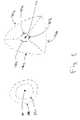
- FIG. 1shows a representation of antenna radiation patterns.
- Omnidirectional antenna 100when used to transmit information produces an omnidirectional radiation pattern, represented by circles 110 and 120 .
- informationis transmitted (and received) on channels in the 2.4 GHz and 5 GHz bands.
- interferencecan limit the effective range of communications.
- a transmitter and antenna such as 100 in FIG. 1has an effective communications range shown by circle 120 .
- This interference rangeis shown as circle 110 of FIG. 1 , covering more area than the communications range shown by circle 120 .
- An approach to improving communicationsis to use directional antennas to direct more RF energy to the desired receiver, such as by using antennas with directional patterns rather than omnidirectional patterns.
- FIG. 1Also shown in FIG. 1 are idealized radiation patterns for 120-degree sectorized antennas 130 a , 130 b , and 130 c .
- Antenna 130 ahas a radiation pattern filling sector 140 a
- antenna 130 bhas a radiation pattern filling sector 140 b
- antenna 130 chas a radiation pattern filling sector 140 c .
- Other approaches in addition to such sectorized, adaptive beam-forming, or smart antennasare often described as electronically steerable and rely on switching antennas and/or antenna elements, or altering the phasing between elements to increase antenna gain to try and mitigate interference and improve communications.
- Such electronically steered antennasmay be used for transmission, reception, or both.
- IEEE 802.11 wireless systemspractice collision avoidance; prior to transmitting on a channel, a device monitors that channel for a predetermined period of time. If the device senses energy or carrier present on the channel, it backs off for a predetermined period of time, thus avoiding collisions which would occur if the device had started transmitting. It is understood that devices that are not within the directional pattern of another device, but are within the communication range, may not be able to hear the directional transmissions and hence may attempt to transmit causing further delays, collisions or interference.
- a well understood solutionis to transmit a separate frame such as short CTS (Clear-to-Send) or equivalent frames in omnidirectional or another pattern prior to the directional transmission to prevent the devices outside of the directional pattern from attempting to transmit.
- This additional transmission of a separate frame prior to the beam-forming patternincurs additional overhead thereby limiting the overall capacity.
- a device transmitting a digital frame of informationtransmits a first portion of the frame using a first antenna radiation pattern, switching to a second antenna radiation pattern at a predetermined point in the frame and transmitting the second portion of the frame using the second antenna radiation pattern. Transmit power delivered to the antenna system may also be varied between the first and second portions of the frame. The point at which the switching from one pattern to another occurs may vary per-frame depending on the nature and mode of transmissions.
- the devicetransmits the first portion of the frame using a wide radiation pattern, such as the omnidirectional pattern 120 of FIG.
- the second portion of the frameusing a narrower pattern, such as that shown using a sectorized antenna such as 130 a producing pattern 140 a of FIG. 1 .
- the selection of the pattern used for the second portion of the framedepends on the location of the receiver.
- the first antenna radiation patternmay combine a wide radiation pattern with a narrower pattern, with only the narrower pattern being used for the second portion.
- FIG. 2shows a sample frame 200 according to 802.11 standards, in this case a high-throughput (HT) frame typical of IEEE 802.11n communications.
- a high-throughput (HT) frametypical of IEEE 802.11n communications.
- Such a frameconsists of a broadcast or legacy portion 215 which has a non-HT preamble 210 , legacy protection and PLCP data (L-SIG) 220 , followed by the HT portion 235 which includes HT-sig 230 , HT-training 240 , and HT-data 250 .
- L-SIGlegacy protection and PLCP data
- One of the purposes of the L-SIG headeris to allow HT 802.11n frames to be identified by older legacy 802.11a/b/g devices which cannot decode 802.11n.
- the HT portion 235 of the frameincludes identification 230 and training 240 fields as well as the data 250 field.
- the broadcast or legacy portion 215 of frame 200consists of legacy long and short training sequences and robust BPSK-OFDM modulation signal field
- the HT portion 235 of frame 200consists of HT long and short training sequences, HT-SIG with BPSK-OFDM and HT-Data with one of the less robust and more efficient OFDM modulations, BPSK, QPSK 16-QAM or 64-QAM.
- the broadcast portion 215 of frame 200is transmitted using the first antenna radiation pattern, and the second portion 235 of frame 200 is transmitted using the second narrower antenna radiation pattern.
- the broadcast portion 215 of frame 200By transmitting broadcast portion 215 of frame 200 over a wider area, nearby devices will sense this portion of the frame and back off, while switching to a narrower antenna pattern for second portion 235 of frame 200 which includes data 250 , and allows more RF energy to be delivered to the target device.
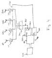
- FIG. 3shows an embodiment of the invention. While the embodiment shows sectorized or switched antennas, it is equally applicable to other electronically steerable antenna systems.
- Antenna 100is a broad-pattern antenna such as an omnidirectional antenna.
- Antennas 130 a , 130 b , and 130 care higher gain directional antennas such as sectorized antennas. As an example, three 120-degree sector antennas may be used, or four 90-degree sector antennas may be used.
- antennas 100 , 130 a , 130 b , 130 care connected respectively to radio frequency (RF) switches 310 , 312 , 314 , and 316 . While these switches are preferably PIN diode switches, other technologies may also be used, provided they have the required switching speeds and isolation. As an example gated power amplifiers may be used. PIN diode switches for RF are known to the art, and are described for example in The PIN Diode Circuit Designers' Handbook published in 1998 by Microsemi Corporation, incorporated herein by reference. PIN diodes are available from numerous sources including Microsemi, Infineon, Vishay, and Avago Technologies. Switches are selected using control lines 318 .
- RFradio frequency
- Switches 310 , 312 , 314 , 316are fed by RF distribution network 300 , which may be a separate RF splitter such as those available from Mini-Circuits Corporation, or this functionality may be incorporated along with switches 310 , 312 , 314 , 316 .
- the overall radiation pattern of an antennamay also be altered or steered by selecting elements of the antenna to feed, or by altering phasing among elements of an antenna or antenna array.
- Such an embodimentwould have a block diagram similar to that of FIG. 3 , where multiple elements 130 a , 130 b , 130 c may be selected at any time, and/or the phasing of elements is varied.
- Switching antenna elements and/or altering phasing of elementsmay also be accomplished using PIN diode switches.
- Transmitter 350 shown in block diagram formincludes power amplifier 360 producing RF output 365 which feeds RF distribution network 300 and the switches and antennas. As shown, transmitter 350 includes antenna sequencer 370 which drives control lines 318 and controlling switches 310 , 312 , 314 , 316 . Transmitter 350 receives a transmit datastream 380 and antenna selection data 390 from controller 500 . Portions of the transmitter such as local oscillators, mixers, I/Q modulators and the like not necessary to understand the invention are not shown.
- controller 500when transmitting a multi-pattern frame, controller 500 provides transmitter 350 and its antenna sequencer 370 with information on which antenna pattern to use in the default configuration, such as for receiving, which antenna pattern to use for the first portion of the frame, and which antenna pattern to use for the second portion of the frame. Switching between the first and second patterns is initiated by transmitter 350 and its antenna sequencer 370 .
- transmitter 350when transmitting a multi-pattern frame 200 , first selects switch 310 and antenna 100 for the first portion of the frame, for example, broadcast portion 215 of FIG. 2 .
- transmitter 350switches off switch 310 and antenna 100 and switches on one of switches 312 , 314 , 316 and accompanying antenna 130 a , 130 b , 130 c .
- the first portion 215 of frame 200is transmitted using a wide pattern
- the second portion 235 of frame 200is transmitted using a narrow pattern.
- transmitter 350 when transmitting a multi-pattern frame 200selects switch 310 with antenna 100 , and one of switches 312 , 314 , 316 and accompanying antenna 130 a , 130 b , 130 c .
- the first portion 215 of frame 200is thus transmitted using wide-coverage antenna 100 and one of the sectorized antennas.
- switch 310 and thus antenna 100are disabled, so only the enabled sectorized antenna 130 a , 130 b , or 130 c is used for transmitting. This results in the first portion 215 of frame 200 being transmitted using a combined wide and narrow pattern, with the second portion 235 only being transmitted using the narrow pattern.
- FIG. 4a second embodiment is shown in FIG. 4 .
- transmitter 350 of FIG. 3generates antenna switching signals 318 directly, and thus must be designed and implemented in accordance with the invention
- the embodiment of FIG. 4uses an unmodified transmitter 350 and implements antenna switching along side the transmitter.
- This embodimentmay be more applicable for use with standard designs and/or prebuilt transmitter and transmitter/receiver assemblies.
- Antenna selection 318is provided by antenna controller 400 which receives antenna data 410 from controller 500 .
- antenna pattern switchingis timing based.
- controller 500sends to antenna controller 400 information on which antenna pattern is to be enabled for the first period, the time of the first period, and information on which antenna pattern is to be used for the second period.
- the time required to transmit the first portion 215 of frame 200is predetermined by controller 500 .
- Controller 500sends 410 antenna selection information and timing information to antenna controller 400 .
- controller 500also signals 410 for antenna controller 400 to start its timing cycle.
- antenna controller 400has a counter chain which has been loaded with the time required to transmit the first portion 215 of frame 200 .
- Antenna controller 400begins counting when transmission begins, as signaled by controller 500 . When the count completes, antenna controller 400 switches antennas as selected. Microsecond resolution is adequate for such a counter.
- CMOScomplementary metal-oxide-semiconductor
- CMOScomplementary metal-oxide-semiconductor
- CMOScomplementary metal-oxide-semiconductor
- XilinxXilinx
- AtmelXilinx
- CypressCypress
- controller 500when transmitting a multi-pattern frame 200 , commands antenna controller 400 to select switch 310 and antenna 100 for the first portion of the frame, for example, broadcast portion 215 of FIG. 2 . Controller 500 also sends antenna controller 400 the duration of the first portion of the frame, and the antenna to select when this portion is complete. Controller 500 then signals the start of the transmission, sending data 380 to transmitter 350 . When the counter in antenna controller 400 expires, it switches off switch 310 and antenna 100 and switches on one of switches 312 , 314 , 316 and accompanying antenna 130 a , 130 b , 130 c.
- controller 500when transmitting a multi-pattern frame 200 , controller 500 commands antenna controller 400 to select switch 310 with antenna 100 , and one of switches 312 , 314 , 316 and accompanying antenna 130 a , 130 b , 130 c . Controller 500 also sends antenna controller 400 the duration of the first portion of the frame. Controller 500 then signals the start of the transmission, sending data 380 to transmitter 350 . The first portion 215 of frame 200 is thus transmitted using wide-coverage antenna 100 and one of the sectorized antennas. When the counter in antenna controller 400 expires, it switches off switch 310 and antenna 100 , so only the enabled sectorized antenna 130 a , 130 b , or 130 c is used for transmitting.
- controller 500also sends the duration of the second portion of the frame, the antenna pattern to be used for receiving subsequent response frames, and duration for staying in the same pattern for receive mode, in addition to the first portion's duration and antenna patterns.
- the antenna controllerswitches to receive mode after the duration of the second portion is completed and/or transmit-to-receive transition is detected by other means so as to receive a response frame such as 802.11 Acknowledgement or 802.11 Block Acknowledgment using the same pattern used for the second portion of the frame, or a different pattern.
- the antenna controlleris instructed to use a specific or default pattern for reception.
- the radiois always in receive mode unless the radio is transmitting a frame or sequence of frames.
- the broadcast portion 215 of the frame 200is transmitted using the first antenna radiation pattern and a first transmit power level
- the second portion 235 of the frame 200is transmitted using the second narrower antenna radiation pattern and a second power level.
- the interference rangeis controlled effectively, while switching to a narrower antenna pattern and a different transmit power for second portion 235 of frame 200 which includes data 250 , and allows more RF energy to be delivered to the target device increasing the reliability of the communication.
- the differences in power levelsmay be implemented using a combination of power-amplifier control, controlling the drive level to the power amplifier, and/or switching attenuators between the transmitter and the antenna.
Landscapes
- Engineering & Computer Science (AREA)
- Computer Networks & Wireless Communication (AREA)
- Signal Processing (AREA)
- Mobile Radio Communication Systems (AREA)
- Radio Transmission System (AREA)
Abstract
Description
Claims (27)
Priority Applications (2)
| Application Number | Priority Date | Filing Date | Title |
|---|---|---|---|
| US12/432,614US8223072B2 (en) | 2009-04-29 | 2009-04-29 | Multi-pattern wireless frame transmission |
| US13/545,851US9041604B2 (en) | 2009-04-29 | 2012-07-10 | Apparatus and method for producing a multi-pattern wireless frame |
Applications Claiming Priority (1)
| Application Number | Priority Date | Filing Date | Title |
|---|---|---|---|
| US12/432,614US8223072B2 (en) | 2009-04-29 | 2009-04-29 | Multi-pattern wireless frame transmission |
Related Child Applications (1)
| Application Number | Title | Priority Date | Filing Date |
|---|---|---|---|
| US13/545,851ContinuationUS9041604B2 (en) | 2009-04-29 | 2012-07-10 | Apparatus and method for producing a multi-pattern wireless frame |
Publications (2)
| Publication Number | Publication Date |
|---|---|
| US20100277368A1 US20100277368A1 (en) | 2010-11-04 |
| US8223072B2true US8223072B2 (en) | 2012-07-17 |
Family
ID=43029997
Family Applications (2)
| Application Number | Title | Priority Date | Filing Date |
|---|---|---|---|
| US12/432,614Active2029-10-23US8223072B2 (en) | 2009-04-29 | 2009-04-29 | Multi-pattern wireless frame transmission |
| US13/545,851ActiveUS9041604B2 (en) | 2009-04-29 | 2012-07-10 | Apparatus and method for producing a multi-pattern wireless frame |
Family Applications After (1)
| Application Number | Title | Priority Date | Filing Date |
|---|---|---|---|
| US13/545,851ActiveUS9041604B2 (en) | 2009-04-29 | 2012-07-10 | Apparatus and method for producing a multi-pattern wireless frame |
Country Status (1)
| Country | Link |
|---|---|
| US (2) | US8223072B2 (en) |
Cited By (15)
| Publication number | Priority date | Publication date | Assignee | Title |
|---|---|---|---|---|
| US20120163356A1 (en)* | 2010-12-27 | 2012-06-28 | Celeno Communications (Israel) Ltd. | Implicit beamforming using partial channel state information |
| US9041604B2 (en) | 2009-04-29 | 2015-05-26 | Aruba Networks, Inc. | Apparatus and method for producing a multi-pattern wireless frame |
| US9197333B1 (en)* | 2011-05-23 | 2015-11-24 | Sprint Spectrum L.P. | Method and system for connection establishment |
| US9397785B1 (en)* | 2010-04-12 | 2016-07-19 | Marvell International Ltd. | Error detection in a signal field of a WLAN frame header |
| US9456357B2 (en) | 2012-07-27 | 2016-09-27 | Aruba Networks, Inc. | Adaptive antenna pattern management for wireless local area networks |
| US10033563B2 (en) | 2013-09-10 | 2018-07-24 | Marvell World Trade Ltd. | Extended guard interval for outdoor WLAN |
| US10135572B2 (en) | 2012-04-03 | 2018-11-20 | Marvell World Trade Ltd. | Physical layer frame format for WLAN |
| US10153930B2 (en) | 2013-10-25 | 2018-12-11 | Marvell World Trade Ltd. | Range extension mode for WiFi |
| US10194006B2 (en) | 2013-10-25 | 2019-01-29 | Marvell World Trade Ltd. | Physical layer frame format for WLAN |
| US10212759B2 (en) | 2013-05-10 | 2019-02-19 | Marvell World Trade Ltd. | Physical layer frame format for WLAN |
| US10218822B2 (en) | 2013-10-25 | 2019-02-26 | Marvell World Trade Ltd. | Physical layer frame format for WLAN |
| US10397033B2 (en) | 2011-02-04 | 2019-08-27 | Marvell World Trade Ltd. | Method and apparatus for generating a PHY data unit |
| US10924170B2 (en) | 2018-02-22 | 2021-02-16 | Celeno Communications (Israel) Ltd. | Smoothing beamforming matrices across sub-carriers |
| US11557835B2 (en) | 2019-07-22 | 2023-01-17 | Nokia Technologies Oy | Apparatus for transmitting and/or receiving radio frequency signals and method of operating such apparatus |
| US11855818B1 (en) | 2014-04-30 | 2023-12-26 | Marvell Asia Pte Ltd | Adaptive orthogonal frequency division multiplexing (OFDM) numerology in a wireless communication network |
Families Citing this family (13)
| Publication number | Priority date | Publication date | Assignee | Title |
|---|---|---|---|---|
| US8599804B2 (en)* | 2009-08-07 | 2013-12-03 | Broadcom Corporation | Distributed signal field for communications within multiple user, multiple access, and/or MIMO wireless communications |
| CN102668405B (en)* | 2009-10-23 | 2015-12-02 | 马维尔国际贸易有限公司 | For the stream instruction number of WLAN |
| US9118103B1 (en)* | 2011-05-31 | 2015-08-25 | Marvell International Ltd. | Position determination using transmit beamforming |
| ES2395580B1 (en)* | 2011-06-28 | 2013-12-20 | Universitat Politècnica De Catalunya | System for the recovery of geophysical parameters using navigation satellite signals |
| WO2015055057A1 (en)* | 2013-10-14 | 2015-04-23 | Harman International Industries, Incorporated | Communication method and system |
| US9939521B2 (en) | 2015-01-09 | 2018-04-10 | Qualcomm Incorporated | Techniques for use in wideband time-of-arrival estimation |
| US10972324B2 (en)* | 2016-01-28 | 2021-04-06 | Qualcomm Incorporated | Dual receiver for millimeter wave communications |
| CN106207449B (en)* | 2016-08-31 | 2019-05-21 | Oppo广东移动通信有限公司 | Antenna device and mobile terminal |
| WO2018091203A1 (en)* | 2016-11-18 | 2018-05-24 | Sony Corporation | Communications apparatus, method and mobile communications system |
| IL280828B2 (en)* | 2018-08-14 | 2024-03-01 | Avx Antenna Inc D/B/A Ethertronics Inc | Method and system for controlling a modal antenna |
| CN110165361A (en)* | 2019-05-20 | 2019-08-23 | 中天宽带技术有限公司 | A kind of list cone of radiation paster antenna and electronic equipment |
| CN114600476B (en) | 2019-11-14 | 2024-01-23 | 以伊索电子股份有限公司名义经营的阿维科斯天线股份有限公司 | Client grouping for point-to-multipoint communications |
| CN113972955B (en)* | 2020-07-22 | 2022-12-30 | 华为技术有限公司 | Distance determination method, device, electronic equipment and computer readable storage medium |
Citations (4)
| Publication number | Priority date | Publication date | Assignee | Title |
|---|---|---|---|---|
| US20080051097A1 (en)* | 2006-07-14 | 2008-02-28 | Samsung Electronics Co., Ltd. | Method of determining channel to be used in wireless network, wireless communication method, and apparatus for the same |
| US7421012B1 (en)* | 2001-11-16 | 2008-09-02 | Marvell International, Ltd. | Antenna diversity technique for wireless communication |
| US7511663B2 (en)* | 2006-10-09 | 2009-03-31 | Sony Deutschland Gmbh | Method and device for transmitting signals in a wireless communication system, receiving device for receiving signals in a wireless communication system, with a special frame structure |
| US20090150537A1 (en)* | 2007-12-10 | 2009-06-11 | John Fanson | Data communication method for a set of hard-real time applications within a network |
Family Cites Families (23)
| Publication number | Priority date | Publication date | Assignee | Title |
|---|---|---|---|---|
| US5890067A (en) | 1996-06-26 | 1999-03-30 | Bnr Inc. | Multi-beam antenna arrays for base stations in which the channel follows the mobile unit |
| KR100304924B1 (en)* | 1997-12-30 | 2001-11-22 | 서평원 | How to Control Handoff Between Frequency in Code Division Multiple Access Cellular System |
| DE10114052C1 (en)* | 2001-03-15 | 2002-07-25 | Hertz Inst Heinrich | Radio transmission method in the interior area for parallel radio transmission of digital partial data streams and mobile radio transmission system |
| US7224685B2 (en)* | 2001-09-13 | 2007-05-29 | Ipr Licensing, Inc. | Method of detection of signals using an adaptive antenna in a peer-to-peer network |
| US7248559B2 (en)* | 2001-10-17 | 2007-07-24 | Nortel Networks Limited | Scattered pilot pattern and channel estimation method for MIMO-OFDM systems |
| JP2004007028A (en)* | 2002-04-26 | 2004-01-08 | Matsushita Electric Ind Co Ltd | Transmission device and transmission method |
| US7103386B2 (en)* | 2003-06-19 | 2006-09-05 | Ipr Licensing, Inc. | Antenna steering and hidden node recognition for an access point |
| US7302278B2 (en) | 2003-07-03 | 2007-11-27 | Rotani, Inc. | Method and apparatus for high throughput multiple radio sectorized wireless cell |
| US8503577B2 (en)* | 2003-07-17 | 2013-08-06 | Agere Systems Llc | Signal quality estimation in a wireless communication system |
| JP4396637B2 (en)* | 2003-08-29 | 2010-01-13 | ソニー株式会社 | Transmitting apparatus and transmitting method |
| FR2861231A1 (en)* | 2003-10-20 | 2005-04-22 | Thomson Licensing Sa | Business/domestic wireless transmitter/receiver station communications network/method having first omni direction station/multiple station frame transfer and second directively exchanged frame set |
| WO2005053339A1 (en)* | 2003-11-27 | 2005-06-09 | Matsushita Electric Industrial Co., Ltd. | Radio communication device and control data retrieving method |
| US7324605B2 (en)* | 2004-01-12 | 2008-01-29 | Intel Corporation | High-throughput multicarrier communication systems and methods for exchanging channel state information |
| US7366464B2 (en)* | 2004-06-04 | 2008-04-29 | Interdigital Technology Corporation | Access point operating with a smart antenna in a WLAN and associated methods |
| US7903973B1 (en)* | 2005-12-23 | 2011-03-08 | Lockheed Martin Corporation | Dynamic temporal duration optical transmission privacy |
| US7894512B2 (en)* | 2007-07-31 | 2011-02-22 | Harris Corporation | System and method for automatic recovery and covariance adjustment in linear filters |
| US8290088B2 (en)* | 2007-08-07 | 2012-10-16 | Research In Motion Limited | Detecting the number of transmit antennas in a base station |
| US7907677B2 (en)* | 2007-08-10 | 2011-03-15 | Intel Corporation | Open loop MU-MIMO |
| KR101454027B1 (en)* | 2007-08-10 | 2014-10-24 | 한국전자통신연구원 | Time Division Multiplexing Communication System and Method Having Parallel Structure |
| JP5233331B2 (en)* | 2008-03-12 | 2013-07-10 | 富士通株式会社 | Wireless base station, wireless terminal, and wireless communication method |
| WO2009137092A1 (en) | 2008-05-09 | 2009-11-12 | Nortel Networks Limited | System and method for supporting antenna beamforming in a cellular network |
| US8223072B2 (en) | 2009-04-29 | 2012-07-17 | Aruba Networks, Inc. | Multi-pattern wireless frame transmission |
| US20130273934A1 (en) | 2012-04-13 | 2013-10-17 | At&T Mobility Ii Llc | Adaptive radio area network coverage |
- 2009
- 2009-04-29USUS12/432,614patent/US8223072B2/enactiveActive
- 2012
- 2012-07-10USUS13/545,851patent/US9041604B2/enactiveActive
Patent Citations (4)
| Publication number | Priority date | Publication date | Assignee | Title |
|---|---|---|---|---|
| US7421012B1 (en)* | 2001-11-16 | 2008-09-02 | Marvell International, Ltd. | Antenna diversity technique for wireless communication |
| US20080051097A1 (en)* | 2006-07-14 | 2008-02-28 | Samsung Electronics Co., Ltd. | Method of determining channel to be used in wireless network, wireless communication method, and apparatus for the same |
| US7511663B2 (en)* | 2006-10-09 | 2009-03-31 | Sony Deutschland Gmbh | Method and device for transmitting signals in a wireless communication system, receiving device for receiving signals in a wireless communication system, with a special frame structure |
| US20090150537A1 (en)* | 2007-12-10 | 2009-06-11 | John Fanson | Data communication method for a set of hard-real time applications within a network |
Non-Patent Citations (1)
| Title |
|---|
| "The Pin Diode Circuit Designers' Handbook", Microsemi-Watertown, 1998, pp. 1-137, Microsemi Corporation. |
Cited By (24)
| Publication number | Priority date | Publication date | Assignee | Title |
|---|---|---|---|---|
| US9041604B2 (en) | 2009-04-29 | 2015-05-26 | Aruba Networks, Inc. | Apparatus and method for producing a multi-pattern wireless frame |
| US9397785B1 (en)* | 2010-04-12 | 2016-07-19 | Marvell International Ltd. | Error detection in a signal field of a WLAN frame header |
| US9819771B1 (en) | 2010-04-12 | 2017-11-14 | Marvell International Ltd. | Error detection in a signal field of a WLAN frame header |
| US10432760B1 (en) | 2010-04-12 | 2019-10-01 | Marvell International Ltd. | Error detection in a signal field of a WLAN frame header |
| US20120163356A1 (en)* | 2010-12-27 | 2012-06-28 | Celeno Communications (Israel) Ltd. | Implicit beamforming using partial channel state information |
| US10397033B2 (en) | 2011-02-04 | 2019-08-27 | Marvell World Trade Ltd. | Method and apparatus for generating a PHY data unit |
| US9197333B1 (en)* | 2011-05-23 | 2015-11-24 | Sprint Spectrum L.P. | Method and system for connection establishment |
| US10742357B2 (en) | 2012-04-03 | 2020-08-11 | Marvell International Ltd. | Physical layer frame format for WLAN |
| US10135572B2 (en) | 2012-04-03 | 2018-11-20 | Marvell World Trade Ltd. | Physical layer frame format for WLAN |
| US9456357B2 (en) | 2012-07-27 | 2016-09-27 | Aruba Networks, Inc. | Adaptive antenna pattern management for wireless local area networks |
| US10212759B2 (en) | 2013-05-10 | 2019-02-19 | Marvell World Trade Ltd. | Physical layer frame format for WLAN |
| US11671296B2 (en) | 2013-09-10 | 2023-06-06 | Marvell Asia Pte Ltd | Extended guard interval for outdoor WLAN |
| US10033563B2 (en) | 2013-09-10 | 2018-07-24 | Marvell World Trade Ltd. | Extended guard interval for outdoor WLAN |
| US10291752B2 (en) | 2013-10-25 | 2019-05-14 | Marvell World Trade Ltd. | Physical layer frame format for WLAN |
| US10389562B2 (en) | 2013-10-25 | 2019-08-20 | Marvell World Trade Ltd. | Range extension mode for WiFi |
| US10218822B2 (en) | 2013-10-25 | 2019-02-26 | Marvell World Trade Ltd. | Physical layer frame format for WLAN |
| US10194006B2 (en) | 2013-10-25 | 2019-01-29 | Marvell World Trade Ltd. | Physical layer frame format for WLAN |
| US11146434B2 (en) | 2013-10-25 | 2021-10-12 | Marvell Asia Pte, Ltd. | Range extension mode for WiFi |
| US11165892B2 (en) | 2013-10-25 | 2021-11-02 | Marvell Asia Pte, Ltd. | Physical layer frame format for WLAN |
| US10153930B2 (en) | 2013-10-25 | 2018-12-11 | Marvell World Trade Ltd. | Range extension mode for WiFi |
| US11962444B2 (en) | 2013-10-25 | 2024-04-16 | Marvell Asia Pte Ltd | Physical layer frame format for WLAN |
| US11855818B1 (en) | 2014-04-30 | 2023-12-26 | Marvell Asia Pte Ltd | Adaptive orthogonal frequency division multiplexing (OFDM) numerology in a wireless communication network |
| US10924170B2 (en) | 2018-02-22 | 2021-02-16 | Celeno Communications (Israel) Ltd. | Smoothing beamforming matrices across sub-carriers |
| US11557835B2 (en) | 2019-07-22 | 2023-01-17 | Nokia Technologies Oy | Apparatus for transmitting and/or receiving radio frequency signals and method of operating such apparatus |
Also Published As
| Publication number | Publication date |
|---|---|
| US9041604B2 (en) | 2015-05-26 |
| US20100277368A1 (en) | 2010-11-04 |
| US20120281785A1 (en) | 2012-11-08 |
Similar Documents
| Publication | Publication Date | Title |
|---|---|---|
| US8223072B2 (en) | Multi-pattern wireless frame transmission | |
| US12328689B2 (en) | Information for wireless communication repeater device | |
| US20210250933A1 (en) | Method and apparatus for improving beam finding in a wireless communication system | |
| KR102031099B1 (en) | The method and apparatus for receiving system information in the wireless communication | |
| CN102026341B (en) | Millimeter-wave communication station and method for scheduling association beamforming training with collision avoidance | |
| US8625565B2 (en) | Millimeter-wave communication station and method for multiple-access beamforming in a millimeter-wave communication network | |
| US9380582B2 (en) | Methods and apparatus for flexible beam communications in random access in system with large number of antennas | |
| KR20150100653A (en) | Method and apparatus for random access in communication system with large number of antennas | |
| KR20190020839A (en) | A method for connecting to a base station with flexible bandwidth | |
| KR20190125410A (en) | Method for transmitting random access channel and user equipment, method for receiving random access channel and base station | |
| CN104521312A (en) | Apparatus and method for random access with multiple antennas in a wireless network | |
| CN111988072A (en) | Techniques for beam shaping at millimeter wave base stations and fast antenna subarray selection at wireless devices | |
| US20200163047A1 (en) | Method for harq feedback in wireless communication system and apparatus therefor | |
| US7768971B2 (en) | Central frequency modification without communication disruption | |
| JP7371232B2 (en) | Method, computer program and wireless network node for null steering beamforming | |
| JP5864722B2 (en) | Wireless terminal and wireless communication method | |
| EP3520557A1 (en) | Methods, network node and wireless device for discontinuous transmission | |
| US20230396304A1 (en) | New beam indication reporting for multi-beam operation | |
| WO2025212001A1 (en) | Random access in wireless communication network | |
| WO2025212002A1 (en) | Random access in wireless communication network |
Legal Events
| Date | Code | Title | Description |
|---|---|---|---|
| AS | Assignment | Owner name:ARUBA NETWORKS, INC., CALIFORNIA Free format text:ASSIGNMENT OF ASSIGNORS INTEREST;ASSIGNOR:PONNUSWAMY, SUBBURAJAN;REEL/FRAME:022620/0918 Effective date:20090429 | |
| STCF | Information on status: patent grant | Free format text:PATENTED CASE | |
| AS | Assignment | Owner name:HEWLETT-PACKARD DEVELOPMENT COMPANY, L.P., TEXAS Free format text:ASSIGNMENT OF ASSIGNORS INTEREST;ASSIGNOR:ARUBA NETWORKS, INC.;REEL/FRAME:035814/0518 Effective date:20150529 | |
| AS | Assignment | Owner name:ARUBA NETWORKS, INC., CALIFORNIA Free format text:ASSIGNMENT OF ASSIGNORS INTEREST;ASSIGNOR:HEWLETT-PACKARD DEVELOPMENT COMPANY, L.P.;REEL/FRAME:036379/0274 Effective date:20150807 | |
| FPAY | Fee payment | Year of fee payment:4 | |
| AS | Assignment | Owner name:HEWLETT PACKARD ENTERPRISE DEVELOPMENT LP, TEXAS Free format text:ASSIGNMENT OF ASSIGNORS INTEREST;ASSIGNOR:ARUBA NETWORKS, INC.;REEL/FRAME:045921/0055 Effective date:20171115 | |
| MAFP | Maintenance fee payment | Free format text:PAYMENT OF MAINTENANCE FEE, 8TH YEAR, LARGE ENTITY (ORIGINAL EVENT CODE: M1552); ENTITY STATUS OF PATENT OWNER: LARGE ENTITY Year of fee payment:8 | |
| MAFP | Maintenance fee payment | Free format text:PAYMENT OF MAINTENANCE FEE, 12TH YEAR, LARGE ENTITY (ORIGINAL EVENT CODE: M1553); ENTITY STATUS OF PATENT OWNER: LARGE ENTITY Year of fee payment:12 |