US8222827B2 - Inductively coupled ballast circuit - Google Patents
Inductively coupled ballast circuitDownload PDFInfo
- Publication number
- US8222827B2 US8222827B2US12/036,348US3634808AUS8222827B2US 8222827 B2US8222827 B2US 8222827B2US 3634808 AUS3634808 AUS 3634808AUS 8222827 B2US8222827 B2US 8222827B2
- Authority
- US
- United States
- Prior art keywords
- primary
- circuit
- load
- power supply
- contact power
- Prior art date
- Legal status (The legal status is an assumption and is not a legal conclusion. Google has not performed a legal analysis and makes no representation as to the accuracy of the status listed.)
- Expired - Fee Related
Links
Images


Classifications
- A—HUMAN NECESSITIES
- A61—MEDICAL OR VETERINARY SCIENCE; HYGIENE
- A61L—METHODS OR APPARATUS FOR STERILISING MATERIALS OR OBJECTS IN GENERAL; DISINFECTION, STERILISATION OR DEODORISATION OF AIR; CHEMICAL ASPECTS OF BANDAGES, DRESSINGS, ABSORBENT PADS OR SURGICAL ARTICLES; MATERIALS FOR BANDAGES, DRESSINGS, ABSORBENT PADS OR SURGICAL ARTICLES
- A61L2/00—Methods or apparatus for disinfecting or sterilising materials or objects other than foodstuffs or contact lenses; Accessories therefor
- A61L2/02—Methods or apparatus for disinfecting or sterilising materials or objects other than foodstuffs or contact lenses; Accessories therefor using physical phenomena
- A61L2/08—Radiation
- A61L2/10—Ultraviolet radiation
- C—CHEMISTRY; METALLURGY
- C02—TREATMENT OF WATER, WASTE WATER, SEWAGE, OR SLUDGE
- C02F—TREATMENT OF WATER, WASTE WATER, SEWAGE, OR SLUDGE
- C02F1/00—Treatment of water, waste water, or sewage
- C02F1/001—Processes for the treatment of water whereby the filtration technique is of importance
- C—CHEMISTRY; METALLURGY
- C02—TREATMENT OF WATER, WASTE WATER, SEWAGE, OR SLUDGE
- C02F—TREATMENT OF WATER, WASTE WATER, SEWAGE, OR SLUDGE
- C02F1/00—Treatment of water, waste water, or sewage
- C02F1/008—Control or steering systems not provided for elsewhere in subclass C02F
- C—CHEMISTRY; METALLURGY
- C02—TREATMENT OF WATER, WASTE WATER, SEWAGE, OR SLUDGE
- C02F—TREATMENT OF WATER, WASTE WATER, SEWAGE, OR SLUDGE
- C02F1/00—Treatment of water, waste water, or sewage
- C02F1/30—Treatment of water, waste water, or sewage by irradiation
- C02F1/32—Treatment of water, waste water, or sewage by irradiation with ultraviolet light
- C02F1/325—Irradiation devices or lamp constructions
- C—CHEMISTRY; METALLURGY
- C02—TREATMENT OF WATER, WASTE WATER, SEWAGE, OR SLUDGE
- C02F—TREATMENT OF WATER, WASTE WATER, SEWAGE, OR SLUDGE
- C02F9/00—Multistage treatment of water, waste water or sewage
- C02F9/20—Portable or detachable small-scale multistage treatment devices, e.g. point of use or laboratory water purification systems
- H—ELECTRICITY
- H01—ELECTRIC ELEMENTS
- H01F—MAGNETS; INDUCTANCES; TRANSFORMERS; SELECTION OF MATERIALS FOR THEIR MAGNETIC PROPERTIES
- H01F38/00—Adaptations of transformers or inductances for specific applications or functions
- H01F38/14—Inductive couplings
- H—ELECTRICITY
- H02—GENERATION; CONVERSION OR DISTRIBUTION OF ELECTRIC POWER
- H02J—CIRCUIT ARRANGEMENTS OR SYSTEMS FOR SUPPLYING OR DISTRIBUTING ELECTRIC POWER; SYSTEMS FOR STORING ELECTRIC ENERGY
- H02J50/00—Circuit arrangements or systems for wireless supply or distribution of electric power
- H02J50/10—Circuit arrangements or systems for wireless supply or distribution of electric power using inductive coupling
- H—ELECTRICITY
- H02—GENERATION; CONVERSION OR DISTRIBUTION OF ELECTRIC POWER
- H02J—CIRCUIT ARRANGEMENTS OR SYSTEMS FOR SUPPLYING OR DISTRIBUTING ELECTRIC POWER; SYSTEMS FOR STORING ELECTRIC ENERGY
- H02J50/00—Circuit arrangements or systems for wireless supply or distribution of electric power
- H02J50/80—Circuit arrangements or systems for wireless supply or distribution of electric power involving the exchange of data, concerning supply or distribution of electric power, between transmitting devices and receiving devices
- H—ELECTRICITY
- H02—GENERATION; CONVERSION OR DISTRIBUTION OF ELECTRIC POWER
- H02J—CIRCUIT ARRANGEMENTS OR SYSTEMS FOR SUPPLYING OR DISTRIBUTING ELECTRIC POWER; SYSTEMS FOR STORING ELECTRIC ENERGY
- H02J50/00—Circuit arrangements or systems for wireless supply or distribution of electric power
- H02J50/90—Circuit arrangements or systems for wireless supply or distribution of electric power involving detection or optimisation of position, e.g. alignment
- H—ELECTRICITY
- H05—ELECTRIC TECHNIQUES NOT OTHERWISE PROVIDED FOR
- H05B—ELECTRIC HEATING; ELECTRIC LIGHT SOURCES NOT OTHERWISE PROVIDED FOR; CIRCUIT ARRANGEMENTS FOR ELECTRIC LIGHT SOURCES, IN GENERAL
- H05B41/00—Circuit arrangements or apparatus for igniting or operating discharge lamps
- H05B41/14—Circuit arrangements
- H05B41/24—Circuit arrangements in which the lamp is fed by high frequency AC, or with separate oscillator frequency
- H—ELECTRICITY
- H05—ELECTRIC TECHNIQUES NOT OTHERWISE PROVIDED FOR
- H05B—ELECTRIC HEATING; ELECTRIC LIGHT SOURCES NOT OTHERWISE PROVIDED FOR; CIRCUIT ARRANGEMENTS FOR ELECTRIC LIGHT SOURCES, IN GENERAL
- H05B41/00—Circuit arrangements or apparatus for igniting or operating discharge lamps
- H05B41/14—Circuit arrangements
- H05B41/36—Controlling
- H—ELECTRICITY
- H05—ELECTRIC TECHNIQUES NOT OTHERWISE PROVIDED FOR
- H05B—ELECTRIC HEATING; ELECTRIC LIGHT SOURCES NOT OTHERWISE PROVIDED FOR; CIRCUIT ARRANGEMENTS FOR ELECTRIC LIGHT SOURCES, IN GENERAL
- H05B47/00—Circuit arrangements for operating light sources in general, i.e. where the type of light source is not relevant
- H05B47/10—Controlling the light source
- H05B47/105—Controlling the light source in response to determined parameters
- H05B47/11—Controlling the light source in response to determined parameters by determining the brightness or colour temperature of ambient light
- H—ELECTRICITY
- H05—ELECTRIC TECHNIQUES NOT OTHERWISE PROVIDED FOR
- H05B—ELECTRIC HEATING; ELECTRIC LIGHT SOURCES NOT OTHERWISE PROVIDED FOR; CIRCUIT ARRANGEMENTS FOR ELECTRIC LIGHT SOURCES, IN GENERAL
- H05B47/00—Circuit arrangements for operating light sources in general, i.e. where the type of light source is not relevant
- H05B47/10—Controlling the light source
- H05B47/175—Controlling the light source by remote control
- H05B47/19—Controlling the light source by remote control via wireless transmission
- H—ELECTRICITY
- H05—ELECTRIC TECHNIQUES NOT OTHERWISE PROVIDED FOR
- H05B—ELECTRIC HEATING; ELECTRIC LIGHT SOURCES NOT OTHERWISE PROVIDED FOR; CIRCUIT ARRANGEMENTS FOR ELECTRIC LIGHT SOURCES, IN GENERAL
- H05B47/00—Circuit arrangements for operating light sources in general, i.e. where the type of light source is not relevant
- H05B47/20—Responsive to malfunctions or to light source life; for protection
- C—CHEMISTRY; METALLURGY
- C02—TREATMENT OF WATER, WASTE WATER, SEWAGE, OR SLUDGE
- C02F—TREATMENT OF WATER, WASTE WATER, SEWAGE, OR SLUDGE
- C02F2201/00—Apparatus for treatment of water, waste water or sewage
- C02F2201/32—Details relating to UV-irradiation devices
- C02F2201/322—Lamp arrangement
- C02F2201/3228—Units having reflectors, e.g. coatings, baffles, plates, mirrors
- C—CHEMISTRY; METALLURGY
- C02—TREATMENT OF WATER, WASTE WATER, SEWAGE, OR SLUDGE
- C02F—TREATMENT OF WATER, WASTE WATER, SEWAGE, OR SLUDGE
- C02F2201/00—Apparatus for treatment of water, waste water or sewage
- C02F2201/32—Details relating to UV-irradiation devices
- C02F2201/326—Lamp control systems
- C—CHEMISTRY; METALLURGY
- C02—TREATMENT OF WATER, WASTE WATER, SEWAGE, OR SLUDGE
- C02F—TREATMENT OF WATER, WASTE WATER, SEWAGE, OR SLUDGE
- C02F2209/00—Controlling or monitoring parameters in water treatment
- C02F2209/005—Processes using a programmable logic controller [PLC]
- C—CHEMISTRY; METALLURGY
- C02—TREATMENT OF WATER, WASTE WATER, SEWAGE, OR SLUDGE
- C02F—TREATMENT OF WATER, WASTE WATER, SEWAGE, OR SLUDGE
- C02F2209/00—Controlling or monitoring parameters in water treatment
- C02F2209/005—Processes using a programmable logic controller [PLC]
- C02F2209/008—Processes using a programmable logic controller [PLC] comprising telecommunication features, e.g. modems or antennas
- C—CHEMISTRY; METALLURGY
- C02—TREATMENT OF WATER, WASTE WATER, SEWAGE, OR SLUDGE
- C02F—TREATMENT OF WATER, WASTE WATER, SEWAGE, OR SLUDGE
- C02F2209/00—Controlling or monitoring parameters in water treatment
- C02F2209/40—Liquid flow rate
- Y—GENERAL TAGGING OF NEW TECHNOLOGICAL DEVELOPMENTS; GENERAL TAGGING OF CROSS-SECTIONAL TECHNOLOGIES SPANNING OVER SEVERAL SECTIONS OF THE IPC; TECHNICAL SUBJECTS COVERED BY FORMER USPC CROSS-REFERENCE ART COLLECTIONS [XRACs] AND DIGESTS
- Y02—TECHNOLOGIES OR APPLICATIONS FOR MITIGATION OR ADAPTATION AGAINST CLIMATE CHANGE
- Y02B—CLIMATE CHANGE MITIGATION TECHNOLOGIES RELATED TO BUILDINGS, e.g. HOUSING, HOUSE APPLIANCES OR RELATED END-USER APPLICATIONS
- Y02B20/00—Energy efficient lighting technologies, e.g. halogen lamps or gas discharge lamps
- Y02B20/40—Control techniques providing energy savings, e.g. smart controller or presence detection
Definitions
- the present inventiongenerally relates to ballasts and more particularly, to an inductively coupled ballast for non-contact power transfer to a secondary circuit or load.
- Ballastsare commonly used to supply power to a wide variety of electrically powered components. Often ballasts are connected directly to the component (or load), for example, by “permanent” connections, such as wires or soldered leads on a circuit board, or by “removable” connections, such as plugs or other connectors. Direct electrical connections present a number of problems. First, direct electrical connections make it difficult to install and remove the load from the ballast. With permanent connections, the electrical leads must be soldered or otherwise secured directly between the ballast and the load. If the ballast or the load is damaged, replacement is complicated by the permanent connections. Removable connections make separation of the ballast and the load easier, but still require some manual manipulation.
- Removable connectorsare also subject to corrosion and may be inadvertently or unintentionally disconnected, for example, by vibrations.
- inductively coupled systemsprovide a number of significant advantages over direct connections.
- inductive couplingsdo not include permanent or removable physical connectors. Instead, the secondary coil of the load (or secondary circuit) simply needs to be placed in the close proximity to the primary coil of the ballast. This greatly simplifies installation and removal of the load.
- the inductive couplingprovide a significant level of isolation between the ballast and the load. This isolation can protect one component from power surges and other potentially damaging abnormalities in the other component.
- ballastsUnfortunately, conventional inductively coupled ballasts suffer from a number of problems associated primarily with efficiency. To provide maximum efficiency, it is desirable for the circuit to operate at resonance. Conventional ballasts are designed to operate at resonance by carefully selecting the components of the ballast in view of the precise characteristics of the load. Any variation in the load can move the circuit dramatically out of resonance. Accordingly, conventional ballasts require very precise selection of the components of the ballast circuit and secondary circuit. In some applications, the impedance of the secondary circuit will vary over time, thereby changing the resonant frequency of the circuit. For example, in many conventional lighting applications, the impedance of the lamp will vary as the lamp is heated and will also vary over the life of the lamp. As a result of these changes, the efficiency of conventional, fixed-frequency ballasts will vary over time.
- ballast control circuitsemploy bipolar transistors and saturating transformers to provide power.
- the ballast control circuitsoscillate at frequencies related to the magnetic properties of the materials and winding arrangements of these transformers.
- Circuits with saturating transformer oscillatorsproduce an output in the category of a square wave, require the transistors of the half bridge to hard-switch under load and require a separate inductor to limit the current through the load.
- Conventional circuitschop the available power supply voltage, developing voltage spikes at the corners of the square wave as a consequence of the current limiting inductor.
- Inductive couplingsrely on electromagnetic induction to transfer power from a primary coil to a secondary coil. The amount of current induced in the secondary coil is a function of the changes in the magnetic field generated by the primary coil. Accordingly, the amount of current transferred through an inductive coupling is dependent, in part, on the waveform of the current driving the primary.
- a square waveformhas relatively small regions of change and therefore provides relatively inefficient transfer of power.
- the present inventiondiscloses an inductively powered ballast circuit having a current sensing circuit that automatically adjusts the frequency of the ballast to maintain operation of the ballast at or near unity power factor.
- the inductively coupled ballast circuitis a self-oscillating half-bridge switching design that operates at high frequencies.
- the inductively coupled ballast circuitself-oscillates partly as a function of the current sensing circuit to maintain resonance, uses MOSFET transistors as switching elements, and is designed to accommodate an air-core transformer coupling arrangement.
- the inductively coupled ballast circuitincludes a control circuit, an oscillator, a driver, a half-bridge switching circuit, and a series resonant tank circuit.
- the secondary circuitpreferably includes a secondary coil and a load.
- the control circuitprovides electrical signals to the oscillator, which, in turn, provides electrical signals to direct the driver.
- the driverthen causes the half-bridge switching circuit to become energized.
- the half-bridge switching circuitenergizes the series resonant tank circuit, which includes a primary coil. Once the series resonant tank circuit, and consequently the primary coil, is energized, the secondary coil becomes inductively energized, thereby providing power to the load.
- the resonant frequency for the inductively coupled ballast circuitis about 100 kHz.
- the secondary circuitpreferably resonates at about 100 kHz as well.
- the resonant frequency of operationcan be adjusted up or down by the control unit to accommodate for convenient component selection.
- selection of the resonant frequencyis a function of the component selection in the series resonant tank and the characteristics of the secondary circuit.
- the series resonant tank circuitincludes an inductive coupler.
- the inductive coupleris positioned adjacent the secondary coil with an air gap therebetween to form an air core transformer. When voltage is applied to the inductive coupler, magnetic flux in the air gap induces voltage in the secondary coil thereby energizing the secondary load.
- the air gapis the distance between the inductive coupler and the secondary coil.
- the air gapmay be selected to provide a current limiting function.
- the air gapprovides a magnetic flux path for inducing sufficient voltage in the secondary coil to establish and maintain an operating point for the secondary load.
- Both the series resonant tank and the secondary loadmay be tuned by proper selection of components to operate at a similar resonant frequency.
- impedance matching between the series resonant tank and the secondary loadmay occur at the resonant frequency. Accordingly, power transfer from the inductive coupler to the secondary coil may be optimized at a resonant frequency to maximize power efficiency.
- the oscillatormay include feedback control for monitoring the series resonance tank.
- the feedback controlmay allow the oscillator to adjust the frequency to minimize reflected impedance from the secondary circuit. Adjusting the frequency to maintain resonance minimizes the reflected impedance and maintains optimum power transfer as the impedance of the secondary circuit varies.
- the present inventionpreferably includes a current limit circuit that monitors the ballast circuit and disables the ballast circuit if the current to the primary exceeds a desired threshold.
- the current limit circuitprotects both the load and the ballast circuit from excessive current.
- the current limit circuitis preferably latched to keep the ballast circuit disabled until reset, for example, by a manual reset switch.
- the current limit circuitmay be configured to disengage the ballast circuit if the current falls outside of a desired operating range. This embodiment is particularly useful in application where the load may be damaged or function improperly when operating under low current.
- FIG. 1is a perspective view of a main housing of the water treatment system with its top shroud removed and a filter assembly and the ultraviolet lamp assembly removed from the base unit.
- FIGS. 2A-Care exploded perspective views of major components of the water treatment system.
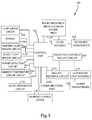
- FIG. 3depicts a block diagram of the major circuits and assemblies of the water treatment system.
- FIG. 4depicts a block diagram of the inductively coupled ballast circuit.
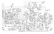
- FIG. 5is an electrical circuit schematic of a portion of the inductively coupled ballast circuit, the ballast feedback circuit and the interlock circuit.
- FIG. 6depicts the secondary coil, the resonant lamp circuit and the ultraviolet lamp of the ultraviolet lamp assembly.
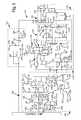
- FIG. 7is an electrical circuit schematic of the starter circuit.
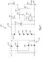
- FIG. 8illustrates an electrical circuit schematic of the radio frequency identification system used in the water treatment system
- FIG. 9is an electrical circuit schematic of the flow sensor circuit.
- FIG. 10is an electrical circuit schematic of the ambient light sensor circuit.
- FIG. 11is an electrical circuit schematic of the ultraviolet light sensor circuit.
- FIG. 12is an electrical circuit schematic of the ambient temperature sensor circuit.
- FIG. 13is an electrical circuit schematic of the audible generation circuit.
- FIG. 14is an electrical circuit schematic of the communication port.
- FIG. 15is a plurality of waveforms representing operation of the current sensing circuit.
- FIG. 16is an electrical circuit schematic of the current limit circuit.
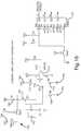
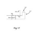
- FIG. 17is an electrical circuit schematic of a portion of an alternative current feedback circuit.
- the present inventionis directed to an inductively coupled ballast circuit that is capable of providing power to a wide variety of electrically powered components in numerous applications.
- embodiments of the ballast circuitwill be described in connection with a water treatment system, and more specifically in connection with the powering of an ultraviolet lamp in a water treatment system.
- the present inventionis well-suited for use in providing power to other types of lamps, such as incandescent, fluorescent and halogen lamps used in numerous lighting applications, such as indoor and outdoor light fixtures, desk lamps, outdoor signage, decorative lighting, automotive lighting, underwater lighting, intrinsically safe lighting, and landscape lighting, to name only a few lighting configurations and applications.
- the present inventionis also well suited for providing power to non-lighting components, such as integrated battery chargers in various electronic components, including cell phones, personal digital assistants and the like.
- Water treatment system 10includes a main housing 12 , a replaceable ultraviolet lamp assembly 14 and a filter assembly 16 .
- the ultraviolet lamp assembly 14 and the filter assembly 16are removable and replaceable from the main housing 12 .
- the main housing 12includes a bottom shroud 18 , a back shroud 20 , a front shroud 22 , a top shroud 24 and an inner sleeve shroud 26 .
- a lens 28accommodates a display 106 (see FIG. 3 ) so that information may be displayed about the status of the water treatment system 10 through the display 106 .
- the ultraviolet lamp assembly 14is securely mounted to the main housing 12 and thereafter the filter assembly 16 is mounted over the ultraviolet lamp assembly 14 and to the main housing 12 .
- the replaceable ultraviolet lamp assembly 14may be made in such a manner that the ultraviolet lamp assembly 14 may not be replaceable.
- the replaceable ultraviolet lamp assembly 14may be interchanged with several different types of electromagnetic radiation emitting assemblies.
- the present inventionshould not be construed to cover only systems that use ultraviolet lamp assemblies and those skilled in the art should recognize that the disclosure of the ultraviolet lamp assembly 14 represents only one embodiment of the present invention.
- the inner sleeve shroud 26includes a plurality of inner sleeve covers 30 , an inlet valve assembly 32 and an outlet cup assembly 34 with an outlet cup 36 .
- a bottom shroud assembly 38is further disclosed that includes the bottom shroud 18 along with an inlet assembly 40 and an outlet assembly 42 .
- An electronics assembly 44fits securely in the bottom shroud 18 , the details of which will be set forth below in detail.
- a magnet holder 46 and a magnet 48are also housed in the top shroud 24 in the illustrated embodiment.
- the ultraviolet lamp assembly 14generally includes a base subassembly 50 , a secondary coil 52 , a bottom support subassembly 54 , a top support assembly 56 , a pair of quartz sleeves 58 , an ultraviolet lamp 60 , an O-ring 62 and a pair of cooperating enclosure reflector subassemblies 64 .
- the secondary coil 52 , the bottom support subassembly 54 and the enclosure reflector subassemblies 64are connected with the base subassembly 50 .
- the enclosure reflector subassemblies 64house the pair of quartz tubes 58 , the ultraviolet lamp 60 and the O-ring 62 .
- the top support assembly 56fits securely over the top of the enclosure reflector assemblies 64 when the ultraviolet lamp assembly 14 is fully assembled.
- the filter assembly 16generally includes a base assembly 66 , a filter block assembly 68 , a filter housing 70 and an elastomeric filter-housing grip 72 .
- the filter block assembly 68fits over the base assembly 66 which, in turn, is encapsulated by the filter housing 70 .
- the filter housing grip 72fits over the top of the filter housing 70 , thereby providing a better grip for removing the filter housing 70 .
- the filter assembly 16filters a flow of water by directing the flow through the filter block assembly 68 before being directed to the ultraviolet lamp assembly 14 .
- FIG. 3illustrates an electronic control system 100 for the water treatment system 10 generally described above.
- the water treatment system 10is controlled by a control unit 102 , which is preferably a microprocessor.
- the control unit 102is electrically connected with the inductively coupled ballast circuit 103 of the present invention.
- the ballast circuit 103includes the ultraviolet lamp assembly 14 and electronic assembly 44 , which are inductively coupled as illustrated by the dotted line in FIG. 4 .
- This control unit 102is also electrically connected to the ultraviolet lamp assembly 14 through two-way wireless communication, as will be set forth in greater detail below.
- control unit 102is capable of generating a predetermined electric signal that is directed to the inductively coupled ballast circuit 103 , which instantaneously energizes the lamp assembly 14 which, in turn, provides high-intensity ultraviolet light that treats the flow of water.
- control unit 102is also electrically connected with a flow sensor circuit 104 , a display 106 , an ambient light sensor circuit 108 , a visible light sensor circuit 110 , a power detection circuit 112 , an ambient temperature sensor circuit 114 , an audio generation circuit 116 , a memory storage device 118 , a communications port 120 , a ballast feedback circuit 122 and a radio frequency identification system 124 .
- an ultraviolet light radio frequency identification transponder 126is connected with the ultraviolet lamp assembly 14 and a filter radio frequency identification transponder 128 is connected with the filter assembly 16 .
- the ultraviolet radio frequency identification transponder 126 and the filter radio frequency identification transponder 128communicate with the radio frequency identification system 124 using two-way wireless communication, as will be set forth in greater detail below.
- the flow sensor circuit 104is used by the control unit 102 to determine when water or fluid is flowing and to keep track of the volume of water or fluid that is being processed by the water treatment system 10 .
- the display 106is driven by the control unit 102 and is used to display information about the status of the water treatment system 10 .
- Several different types of displaysare known in the art and may be used in the present invention; however, the preferred display is a vacuum florescent display.
- the ambient light sensor circuit 108measures the amount of ambient light and, in turn, provides electrical signals to the control unit 102 so that it can adjust the intensity of the display 106 accordingly.
- the visible light sensor circuit 110provides the control unit 102 with electrical signals related to the intensity level of the light that is being emitted by the ultraviolet lamp assembly 14 . This is important because these signals allow the control unit 102 to increase or decrease the intensity of the electromagnetic radiation being emitted by the ultraviolet lamp assembly 14 .
- the visible light sensor circuit 110may be interchanged with various electromagnetic radiation sensor circuits that are capable of sensing the intensity of electromagnetic radiation that is emitted from various electromagnetic radiation emitting devices that may be used in the present invention.
- the power detection circuit 112provides the control unit 102 with electrical signals that indicate the presence or absence of power to the water treatment system 10 .
- Poweris provided to the water treatment system 10 from an external power source, such as a conventional power outlet.
- an external power sourcesuch as a conventional power outlet.
- the ambient temperature sensor circuit 114measures the ambient temperature of the atmosphere so that the water treatment system 10 can maintain a temperature level above freezing or some other predetermined temperature setting.
- the control unit 102can energize the ultraviolet lamp 60 to generate heat if necessary.
- the audio generation circuit 116is used by the control unit 102 to generate audible enunciations. The audible enunciations typically occur during predetermined system states that are experienced by the water treatment system 10 . These predetermined system states are recognized by the control unit 102 which, in turn, activates the audio generation circuit 116 to create the audible enunciation.
- the memory storage device 118is also electrically connected with the control unit 102 .
- the memory storage device 118is used to store various data values related to the water treatment system 10 and its related components.
- the memory storage device 118is an EEPROM or some other equivalent storage device. Those skilled in the art would recognize that various memory storage devices are available that could be used in the present invention.
- the communications port 120is also electrically connected with the control unit 102 , which provides the water treatment system 10 with the ability to conduct bi-directional communication between the control unit 102 and a peripheral device, such as a personal computer or hand-held monitoring device.
- the communications port 120uses the RS-232 communication platform to communicate with the peripheral device.
- the communications port 120may also be connected with the ultraviolet lamp assembly 14 and the filter assembly 16 to monitor and control various operational characteristics of these devices in other embodiments.
- the radio frequency identification system 124is used to report information to the control unit 102 about the ultraviolet lamp assembly 14 and the filter assembly 16 .
- the radio frequency identification system 124uses signals from the ultraviolet light radio frequency identification transponder 126 and the filter radio frequency identification transponder 128 to report various information to the control unit 102 .
- the ultraviolet light radio frequency identification transponder 126 and the filter radio frequency identification transponder 128communicate with the radio frequency identification system 124 using wireless communication. Since the ultraviolet lamp assembly 14 and the filter assembly 16 are designed to be replaceable at the end of its useful life, each ultraviolet lamp assembly 14 and filter assembly 16 contains a transponder 126 , 128 that stores information specific to each device. Those skilled in the art would recognize that the ultraviolet light radio frequency transponder could be used in conjunction with other electromagnetic radiation emitting devices or assemblies.
- the radio frequency identification system 124is set forth in greater detail below.
- the ultraviolet lamp assembly 14is energized by the inductively coupled ballast circuit 103 that is electrically connected with the control unit 102 .
- the inductively coupled ballast circuit 103is a self-oscillating, half-bridge switching design that operates at high frequencies.
- the inductively coupled ballast circuit 103self-oscillates once resonance is achieved, uses MOSFET transistors as switching elements, and is designed to accommodate an air-core transformer coupling arrangement, which simplifies the design of the ultraviolet lamp assembly 14 .
- the ultraviolet lamp assembly 14 or other electromagnetic radiation emitting assembliesmay be readily replaced because of the air-core transformer coupling arrangement created by the inductively coupled ballast circuit 103 .
- the inductively coupled ballast circuit 103 of the described embodimentgenerally includes a control circuit 142 , an oscillator 144 , a driver 146 , a half-bridge switching circuit 148 , and a series resonant tank circuit 150 .
- the ultraviolet lamp assembly 14generally includes the secondary coil 52 (see FIG. 2 ), a resonant lamp circuit 152 and the ultraviolet lamp 60 .
- the oscillator 144is electrically connected with the control unit 102 , which energizes the oscillator 144 by providing electric signals to the control circuit 142 .
- the oscillator 144provides electrical signals to direct the driver 146 , which then causes the half-bridge switching circuit 148 to become energized.
- the half-bridge switching circuit 148energizes the series resonant tank circuit 150 that, in turn, inductively energizes the ultraviolet lamp 60 in the ultraviolet lamp assembly 14 .
- the ultraviolet lamp assembly 14includes the secondary coil 52 , the resonant lamp circuit 152 and the ultraviolet lamp 60 while the electronic assembly 44 houses the control circuit 142 , the oscillator 144 , the driver 146 , the half-bridge switching circuit 148 and the series resonant tank circuit 150 .
- the secondary coil 52 in the ultraviolet lamp assembly 14becomes inductively energized as illustrated by the dotted line in FIG. 4 .
- the resonant frequency for the ballast circuit 103is about 100 kHz.
- the ultraviolet lamp assembly 14resonates at about 100 kHz as well.
- the frequency of operationmay be varied to maintain resonance of the series resonant tank circuit 150 and the ultraviolet lamp assembly 14 as discussed in detail below.
- the resonant frequencymay be any desired frequency selected as a function of the component selection in the series resonant tank circuit 150 and the ultraviolet lamp assembly 14 .
- the control circuit 142is electrically connected with the control unit 102 and the oscillator 144 .
- the control circuit 142includes a plurality of resistors 156 , 158 , 160 , 162 , 164 , 166 , a plurality of capacitors 168 , 170 172 , a diode 174 , a first operational amplifier 176 and a second operational amplifier 178 .
- resistor 156is connected with a first direct current (“DC”) power source 180 , the output of the control unit 102 and resistor 158 .
- Resistor 158is further connected with diode 174 , resistor 160 and capacitor 168 .
- the first DC power source 180is connected with capacitor 168 , which is also connected with diode 174 .
- Diode 174is further connected with a ground connection 182 , as those skilled in the art would recognize.
- Resistor 160is connected with the negative input of operational amplifier 176 and the positive input of operational amplifier 178 to complete the current path from the control unit 102 to the operational amplifiers 176 , 178 .
- resistor 162is connected with a second DC power source 184 and in series with resistors 164 and 166 .
- Resistor 166is connected with the ground connection 182 and capacitor 170 , which is, in turn, connected with the first DC power source 180 and resistor 164 .
- the positive input of operational amplifier 176is electrically connected between resistors 162 and 164 , which provides a DC reference voltage to operational amplifier 176 during operation.
- the negative input of operational amplifier 178is electrically connected between resistors 164 and 166 , which provides a DC reference voltage to operational amplifier 178 during operation.
- the output of operational amplifiers 176 and 178is connected with the oscillator 144 , as set forth in detail below.
- the control circuit 142turns the oscillator 144 on and off based on input from the control circuit 102 and the magnetic interlock sensor 192 , as described in more detail below.
- the control circuit 142receives electrical signals from the control unit 102 and, in turn, acts as a window comparator that only switches the oscillator 144 on when the input voltage produced by the control unit 102 is within a certain voltage window.
- the preferred signal from the control unit 102is an AC signal that, together with its duty cycle, allows the control unit 102 to turn the ultraviolet lamp 60 on and off through the remaining components of the inductively coupled ballast circuit 103 , as will be set forth below.
- the control circuit 142also prevents false triggering and allows positive control if the control unit 102 fails.
- the first DC power source 180 and the second DC power source 184provide power to the circuits depicted in FIG. 5 .
- DC power supply circuitsare well known in the art and beyond the scope of the present invention.
- a +14 VDC and a +19 VDC signalis used, as indicated throughout the figures.
- 300 VDCis used to supply power to the half-bridge switching circuit 148 to optimize power transfer.
- the output of the control circuit 142is connected with an interlock circuit 190 to prevent the ultraviolet lamp 60 from becoming energized if the water treatment system 10 is not properly assembled.
- the interlock circuit 190includes a magnetic interlock sensor 192 , a plurality of resistors 193 , 194 , 196 , 198 , 200 , 202 , 204 , a transistor 206 and a diode 208 .
- the magnetic interlock sensor 192is positioned so that if the top shroud 24 is not securely positioned on the inner sleeve shroud 26 , the water treatment system 10 will not energize the ultraviolet lamp 60 .
- the magnetic interlock sensor 192may be placed in other convenient places of the water treatment system 10 as well.
- the magnetic interlock circuit 190operates by directing the output of the control circuit 142 to the ground connection 182 , through transistor 206 , if the magnetic interlock sensor 192 detects that the water treatment system 10 is not assembled properly, as set forth above. As those skilled in the art would recognize, if the water treatment system 10 is not assembled properly, the output of the magnetic interlock sensor 192 causes the current flowing through resistors 194 , 196 and 198 to energize the gate of transistor 206 , which thereby shorts the output signal of the control circuit 142 to the ground connection 182 .
- the magnetic interlock sensor 192is powered by the second DC power source 184 through resistor 193 and is also connected with the ground connection 182 .
- the magnetic interlock sensor 192sends a signal to the control unit 102 , through the combination of resistors 200 , 202 and 204 , diode 208 , first DC power source 180 and second DC power source 184 .
- This signalalso allows the control unit 102 to determine when the water treatment assembly 10 is not assembled properly.
- the interlock circuit 190provides two methods of ensuring that the ultraviolet lamp 60 is not energized if the water treatment system 10 is not assembled properly. The magnetic interlock is not necessary for the operation of the present invention.
- the oscillator 144provides electrical signals that energize the driver 146 while the water treatment system 10 is treating a flow of water.
- the oscillator 144begins operating immediately once an electrical signal is sent from the control unit 102 , through control circuit 142 , as set forth above.
- the oscillator 144may also be controlled by any other mechanism capable of activating and deactivating the oscillator 144 .
- the illustrated oscillator 144comprises an operational amplifier 210 , a linear bias resistor 212 , a buffer circuit 214 , a buffer feedback protect circuit 216 and a current sensing circuit 218 .
- the operational amplifier 210receives input signals from the control circuit 142 , the linear bias resistor 212 and the current sensing circuit 218 .
- the operational amplifier 210is also connected with the second DC power source 184 and the ground connection 182 , which energizes the operational amplifier 210 .
- the illustrated buffer circuit 214comprises a first transistor 220 , a second transistor 222 and a pair of resistors 224 , 226 .
- the output of operational amplifier 210is connected with the gates of transistors 220 , 222 , thereby controlling operation of transistors 220 , 222 .
- the second DC power source 184is connected with resistor 224 , which is also connected with collector of transistor 220 .
- the emitter of transistor 220is connected with resistor 226 , the emitter of transistor 222 and the input of the driver 146 .
- the collector of transistor 222is connected with ground connection 182 .
- the buffer circuit 214buffers the output signal from the operational amplifier 210 and prevents load changes from pulling the frequency of oscillation.
- the buffer circuit 214increases the effective gain of the inductively coupled ballast circuit 103 , which helps ensure a quick start of the oscillator 144 .
- the buffer feedback protect circuit 216comprises a pair of diodes 228 , 230 that are electrically connected with the output of the buffer circuit 214 by resistor 226 .
- the second DC power source 184is connected with the cathode of diode 228 .
- the anode of diode 228 and the cathode of diode 220are connected with resistor 226 and the linear bias resistor 212 .
- the linear bias resistor 212provides bias feedback signals to the negative input of operational amplifier 210 .
- the anode of diode 230is connected with ground connection 182 , which completes the buffer feedback protect circuit 216 .
- the buffer feedback circuit 216protects the buffer circuit 214 from drain to gate Miller-effect feedback during operation of the water treatment system 10 .
- the current sensing circuit 218includes a first multi-winding transformer 232 , a plurality of resistors 234 , 236 , 238 , a pair of diodes 240 , 242 , and a capacitor 244 .
- the transformer 232preferably includes a primary having two windings that are connected in parallel between the output of the half-bridge switching circuit 148 and the input of the series resonant tank circuit 150 as illustrated in FIG. 5 .
- the transformer 232preferably includes a primary with two windings connected in parallel rather than a single winding to reduce the total reactance on the primary side of the transformer, thereby reducing the reactive impact of the transformer 232 on the tank circuit 150 .
- the primary side of the transformermay be divided into a different number of windings.
- the transformer 232may include only a single winding where reduction of the reactive impact of the transformer is not important or may include three or more windings where even further reduction of the reactive impact of the transformer 232 is desired.
- the first lead of the secondary coil of transformer 232is electrically connected with resistors 234 , 236 , 238 , the diodes 240 , 242 and the positive input of the operational amplifier 210 .
- the second lead of the secondary coil of the transformer 232is connected with resistor 238 , the cathode of diode 242 , the anode of diode 240 and capacitor 244 .
- resistor 238 and diodes 242 , 244are connected in parallel with the secondary winding of transformer 232 , as illustrated in FIG. 5 .
- Capacitor 244is also electrically connected with the negative input of operational amplifier 210 .
- resistor 234is connected with the second DC power source 184 and resistor 236 is connected with the ground connection 182 .
- Resistors 234 , 236 and 238protect the operational amplifier 210 from current overload and diodes 240 , 242 clip the feedback signal that is sent to the input of the operational amplifier 210 .
- the oscillator 144receives signals from the control circuit 142 that charge capacitor 244 , which, in turn, sends an electrical signal to the negative input of the operational amplifier 210 .
- the output of the operational amplifier 210is electrically connected to the driver 146 through the buffer circuit 214 .
- the driver 146energizes the half-bridge switching circuit 148 , which in turn provides power to the tank circuit 150 ultimately powering inductive coupler 270 .
- the transformer 232is connected in the current path between the half-bridge switching circuit 148 and the tank circuit 150 .
- the transformer 232sends electrical signals back through resistors 234 , 236 and 238 , which limit the current, to the inputs of the operational amplifier 210 to provide a current sensing feedback. As described in more detail below, the current sensing feedback provided by transformer 232 allows the oscillator 144 to self-resonate despite changes in the load.
- the inductively coupled ballast circuit 103remains oscillating until the control unit 102 shuts the water treatment system 10 down or transistor 206 of the interlock circuit 190 pulls the input to the oscillator 144 low.
- the current sensing circuit 218provides feedback to the operational amplifier 210 that controls the timing of the oscillator 144 so that the oscillator 144 does not impair the tank circuit's 150 inherent tendency to oscillate at resonant frequency.
- the current in the series resonant tank circuit 150flows through the primary coils of transformer 232 , thereby inducing a voltage in the secondary coil of transformer 232 .
- the AC signal generated by the transformer 232is superimposed upon a DC reference voltage set by resistors 234 and 236 .
- the operational amplifier 210is preferably a conventional difference operational amplifier providing an output based, in part, on the difference between the amplitude of the signal on the positive lead and the amplitude of the signal of the negative.
- the output of the operational amplifier 210oscillates above and below the reference voltage in accordance with the oscillating signal of the current feedback circuit.
- the operational amplifier 210is preferably alternately driven between saturation and cutoff, thereby providing a quasi-square wave output.
- transistor 220is driven to “on,” while transistor 222 is driven to “off,” thereby charging capacitor 248 and discharging capacitor 250 .
- transistor 222is driven to “on” while transistor 220 is driven to “off,” thereby discharging capacitor 248 and charging capacitor 250 .
- This alternating charging/discharging of capacitors 248 and 250results in an alternating signal being applied to the primary coil of the driver 146 , as described in more detail below.
- the frequency shifting (or resonance seeking) operation of the circuitis described in more detail with reference to FIG. 15 .
- the current in the inductive coupler 270is represented by waveform 600
- the voltage in the current transformer 232is represented by waveform 602
- the current feedback signalis represented by waveform 604 (shown without clipping of diodes 240 and 242 ).
- the operational amplifier 210is alternately driven between saturation and cutoff with a transition period interposed between the saturation and cutoff portions of the waveform. The length of the transition period is dictated by the slope of the current feedback signal.
- the timing of the operational amplifier 210is dependent on the length of the transition period. By varying the length of the transition period, the timing of the transitions in the operational amplifier 210 output signal is controlled. This shift in timing is perpetuated through the driver 146 and half-bridge switching circuit 148 having the affect of varying the frequency and also possibly the amplitude of the signal in the tank circuit 150 . The altered signal in the tank circuit 150 is reflected into the current feedback signal by the current transformer 232 to perpetuate the frequency shift. When the load on the secondary coil 52 increases, a corresponding increase occurs in the amplitude of the current in the tank circuit 150 . This increased signal is represented by waveform 606 in FIG. 15 . The increased signal in the tank circuit 150 results in a corresponding increase in the voltage in the current transformer 232 .
- the increased voltage in the current transformer 232is represented by waveform 608 .
- the increased voltage in the current transformer 232finally results in an increase in the amplitude of the current feedback signal, represented by waveform 610 (shown without clipping of diodes 240 and 242 ).
- the increased current feedback signalhas a greater slope at the zero crossings and therefore causes the operational amplifier 210 to transition from one state to the other sooner in time. This in turn causes the transistors 220 and 222 to switch sooner in time and the AC signal applied to the driver 146 to alternate sooner in time.
- the shift in timing of the signals applied by the half-bridge switching circuit 148has the effect of increasing the frequency and possibly the amplitude of the inherent oscillating signal in the tank circuit 150 , thereby shifting, or “truncating,” the timing of the signal in the tank circuit 150 .
- the truncated signal in the tank circuit 150is reflected into the current sensing circuit 218 . This varies the current feedback signal applied to the operational amplifier 210 , thereby perpetuating the frequency shift and effecting an increase in the frequency of the oscillator. In this way the oscillator 144 and driver 146 permit the tank circuit 150 to shift its frequency to remain at resonance despite a change in load.
- the frequency of the oscillator 144decreases in a manner essentially opposite that described above in connection with an increase in frequency.
- the decreased loadresults in decreased current in the tank circuit 150 .
- the decreased current feedback signalhas a decreased slope, and accordingly causes the operational amplifier 210 to complete the transition between saturation and cutoff later in time.
- the transistors 220 and 222also transition later in time, thereby shifting the timing of the driver 146 and the timing of the switching circuit 148 .
- the net effect of the shift in the timing of the switching circuit 148is to shift, or “extend”, the frequency and possibly vary the amplitude of the signal in the tank circuit 150 .
- the extended signalis reflected into the current sensing circuit 218 where it is returned to the operational amplifier 210 to perpetuate the decrease in frequency of the oscillator 144 .
- Optimal performanceis achieved when the half-bridge switching circuit 148 alternates at the zero crossings of the current signal in the tank circuit 150 . This provides optimal timing of the energy supplied by the switching circuit 148 to the tank circuit 150 . In some applications, it may be necessary or desirable to shift the phase of the current feedback signal to provide the desired timing.
- FIG. 17illustrates a portion of an alternative current sensing circuit 218 ′, which includes an RC circuit configured to shift the phase of the current feedback signal 120 degrees.
- the current sensing circuit 218 ′is essentially identical to the current sensing circuit 218 of the above described embodiment, except that it includes two capacitors 800 , 802 and two resistors 804 , 806 that are connected along the leads extending back to the operation amplifier 210 .
- FIG. 17further illustrates that the secondary of the current transformer 232 can be connected to ground 182 to provide a zero reference, if desired. If the current transformer 232 is connected to ground 182 , resistor 238 is eliminated.
- the output of the oscillator 144is electrically connected with the driver 146 .
- the driver 146is a multi-winding transformer that provides power to the half-bridge switching circuit 148 .
- Transformer 246is the preferred driver 146 in the illustrated embodiment because the phasing arrangement of the transformer 246 insures that the half-bridge switching circuit 148 will be alternately driven, which avoids cross conduction.
- a double arrangement of capacitors 248 , 250is electrically connected with the primary winding of transformer 246 , thereby preventing DC current saturation in the transformer 246 .
- Capacitor 246is also connected with the ground connection 182 and capacitor 250 is also connected with the second DC power source 184 .
- the transformer 246includes two secondary coils that are electrically connected to opposite legs of the half-bridge switching circuit 148 so that the half-bridge switching circuit 148 receives energy from transformer 246 .
- the half-bridge switching circuit 148which is also illustrated in FIG. 5 , is electrically arranged as a MOSFET totem pole half-bridge switching circuit 252 that is driven by both secondary coils of transformer 246 .
- the MOSFET totem pole half-bridge switching circuit 252includes a first MOSFET transistor 254 and a second MOSFET transistor 256 that provide advantages over conventional bipolar transistor switching circuits. Energy is transferred from the driver 146 to the MOSFET transistors 254 , 256 through a plurality of resistors 258 , 260 , 262 , 264 .
- MOSFET transistors 254 , 256are designed to soft-switch at zero current and exhibit only conduction losses during operation.
- the output generated by MOSFET transistors 254 , 256is more in the form of a sine wave that has fewer harmonics than that generated by traditional bipolar transistors.
- Using MOSFET transistors 254 , 256also provides advantages by reducing radio frequency interference that is generated by the MOSFET transistors 254 , 256 while switching during operation.
- the first secondary coil of transformer 246is connected with resistor 258 and resistor 260 .
- the second secondary coil of transformer 246is connected with resistor 262 and resistor 264 .
- Resistor 260is connected with the gate of MOSFET transistor 254 and resistor 264 is connected with the gate of MOSFET transistor 256 .
- the first secondary coil of transformer 246 and resistor 258are connected with the source of MOSFET transistor 254 .
- the second secondary coil of transformer 246 and resistor 264are connected with the gate of MOSFET transistor 256 .
- MOSFET transistor 254The drain of MOSFET transistor 254 is connected with the second DC power source 184 and the source of MOSFET transistor 254 is connected with the drain of MOSFET transistor 256 .
- the source of MOSFET transistor 256 and resistor 262are connected with the ground connection 182 .
- a further benefit of the driver 146is that multi-winding transformer 246 is a very convenient way to apply gate drive voltage to the MOSFET transistors 254 , 256 that exceeds the second DC power source 184 .
- the MOSFET transistors 254 , 256provide further advantages because they have diodes inherent in their design that protect the MOSFET totem pole half-bridge switching circuit 252 from load transients. In addition, over-voltages reflected from the series resonant tank circuit 150 , by changes in load, are returned to supply rails by the inherent diodes within MOSFET transistors 254 , 256 .
- the output of the half-bridge switching circuit 148is connected with the input of the series resonant tank circuit 150 , which, in turn, inductively energizes the secondary coil 52 of the ultraviolet lamp assembly 14 ( FIG. 4 ).
- the current sensing circuit 218 of the oscillator 144is connected with the output of the half-bridge switching circuit 148 and the input of the series resonant tank circuit 150 to provide current sense feedback to operational amplifier 210 of the oscillator 144 during operation.
- the primary coil of the transformer 232is connected in series between the output of the half-bridge switching circuit 148 and the input of the series resonant tank circuit 150 as illustrated in FIG. 5 .
- the series resonant tank circuit 150comprises an inductive coupler 270 , the parallel combination of a pair of tank capacitors 271 , 272 , a pair of diodes 274 , 276 and a capacitor 278 .
- the inductive coupler 270is connected to the primary coil of transformer 232 and tank capacitors 271 , 272 .
- Tank capacitor 271is also connected with the second DC power source 184 and tank capacitor 272 is also connected with the ground connection 182 .
- tank capacitor 271 and the second DC power source 184are connected with the anode of diode 274 .
- the cathode of diode 274 and capacitor 278are both connected with the second DC power source 184 .
- Capacitor 278is connected with the anode of diode 276 and the ground connection 182 .
- Tank capacitor 272is also connected the cathode of diode 276 .
- the series resonant tank circuit 150sees all of the stray inductances of the component combination of the inductively coupled ballast circuit 103 . This is relevant because the stray inductance, which is the combined inductance seen by the series resonant tank circuit 150 , will limit the power transfer to the load (the ultraviolet light assembly 14 ) if its precludes the system from operating outside of resonance.
- the inductance of the secondary coil 52 and the resonant lamp circuit 152are also reflected impedance values that help determine and limit the power that is delivered to the secondary coil 52 of the ultraviolet lamp assembly 14 .
- brute force oscillator/transformer combinationshave power transfer limits because of stray and reflected inductance. In other words, the inductance of transformers and capacitors appears in series with the load thereby limiting power transfer capability.
- the frequency of operation for the series resonant tank circuit 150is set near 100 KHz, which is determined by the inductance of the inductive coupler 270 and the parallel capacitance value of tank capacitors 271 , 272 , which are 0.1 uF capacitors in the illustrated embodiment.
- Tank capacitors 271 , 272must have low dissipation factors and be able to handle high levels of current, which is about 14 amps at start up. This resonant frequency may be adjusted up or down and has been selected only for convenient component selections.
- the ballast circuit 103seeks resonance through a feedback signal from the current sensing circuit 218 . The current feedback signal is proportional to the current in the resonant tank circuit 150 .
- the range of frequencies through which the ballast circuit 103 can search for resonanceare readily varied by adjusting the values of the tank capacitors 271 , 272 . For example, by increasing the value of the tank capacitors 271 , 272 , the range can generally be decreased.
- the inductive coupler 270 of the illustrated embodimentincludes 10 turns of wire to generate the power required to inductively energize the secondary coil 52 in the ultraviolet lamp assembly 14 .
- the inductive coupler 270is preferably positioned in the outlet cup 36 (see FIG. 2A ) of the water treatment system 10 and wire is wrapped around the outlet cup 36 in a diameter of about 3.5 inches.
- litz wireis used for the inductive coupler 270 because litz wire is especially efficient in both performance and operating temperature, due to a skin effect caused by operating at 100 kHz.
- the inductive coupler 270inductively energizes the secondary coil 52 of the ultraviolet lamp assembly unit 14 during operation.
- the secondary coil 52 of the ultraviolet lamp assembly unit 14is positioned in the outlet cup 36 and the inner sleeve shroud 26 when the water treatment system 10 is assembled.
- the secondary coil 52has 55 turns of small diameter wire that is wrapped around the secondary coil 52 in a diameter of about two inches. It is important to note that the coupling between the outlet cup 36 and the base subassembly 50 , which houses the secondary coil 52 , is designed to be very tolerant of gaps and misalignment. In fact, gaps are used to adjust the coupling coefficient, thereby adjusting the operating point of the ultraviolet lamp 60 .
- the permeance of the air gap between the inductive coupler 270 and the secondary coil 52may be adjusted by changing the distance between the inductive coupler 270 and the secondary coil 52 , as known in the art.
- the air gap within the air core transformer formed with the inductive coupler 270 and the secondary coil 52may be selectively adjusted to limit power transfer from the inductive coupler 270 to the secondary coil 52 .
- selective adjustment of the air gapmay adjust the control response of the oscillator 144 . Accordingly, selection of the permeance of the air gap balances overcurrent protection of the inductively coupled ballast circuit 103 with the bandwidth and responsiveness of the oscillator 144 when the secondary coil 52 is inductively energized.
- inductive energization of the secondary coil 52occurs when the inductive coupler 270 induces a magnetic flux in the air gap between the secondary coil 52 and the inductive coupler 270 .
- the magnetic fluxis an alternating flux with a frequency that is preferably controlled by the oscillator 144 in an effort to maintain resonance.
- the oscillator 144may control the frequency at close to the resonant frequency of the series resonant tank circuit 150 and the ultraviolet lamp assembly unit 14 .
- the current sensing circuit 218monitors the reflected impedance in the series resonance tank circuit 150 to allow the inductively coupled ballast circuit 103 to self-oscillate to a frequency which optimizes power transfer efficiency. If, for example, the impedance reflected by the ultraviolet light assembly 14 to the series resonant tank circuit 150 shifts slightly, the current sensing circuit 218 may adjust the frequency to correct for the shift in power transfer efficiency.
- the inductively coupled ballast circuit 103may be optimized for efficient operation while maintaining desirable levels of overcurrent protection.
- the configuration of the air core transformerprovides for simple and efficient replacement of the ultraviolet light assembly 14 .
- the present inventionprovides further advantages by providing a coupling that does not require special contacts for the ultraviolet lamp assembly 14 because of the inductively coupled ballast circuit 103 .
- the configurationeliminates the need for conductors or other similar power transfer mechanism that may compromise waterproofing, corrode and/or otherwise malfunction.
- the inductively coupled ballast circuit 103 set forth abovemay be readily incorporated into other lighting systems or other systems requiring the transmission of electric power, and provides advantages over prior art ballast circuits because it drives lamps and other loads without requiring a physical connection and because it seeks resonance with the secondary.
- the inductively coupled ballast circuit 103is also capable of instantaneously energizing several different styles of lamps, bulbs and other loads.
- the ballast feedback circuit 122is electrically connected with the inductive coupler 270 of the series resonant tank circuit 150 and the control unit 102 .
- the ballast feedback circuit 122provides feedback to the control unit 102 while the inductively coupled ballast circuit 103 is driving the ultraviolet lamp 60 .
- Thisallows the control unit 102 to monitor the energy being provided by the inductive coupler 270 to the secondary coil 52 of the ultraviolet lamp assembly 14 .
- Thisprovides the control unit 102 with the ability to determine if the ultraviolet lamp 60 is on or off and also, in other embodiments, the amount of current and voltage being applied to the ultraviolet lamp 60 .
- the ballast feedback circuit 122includes an operational amplifier 280 , a pair of resistors 282 , 284 , a pair of diodes 286 , 288 and a capacitor 290 .
- the signal from the series resonant tank circuit 150is directed to the anode of diode 286 .
- the cathode of diode 286is connected with capacitor 290 and resistor 282 .
- resistor 282is connected with the anode of diode 288 , resistor 284 and the positive input of operational amplifier 280 .
- Resistor 284is also connected with the positive input of operational amplifier 280 and the first DC power source 180 .
- Capacitor 290is also connected with the first DC power source 180 , while the cathode of diode 288 is connected with the second DC power source 184 .
- the negative input of operational amplifier 280is connected directly with the output of operational amplifier 280 .
- the output of operational amplifier 280is connected with the control unit 102 , thereby providing the feedback signal from operational amplifier 280 to the control unit 102 .
- the ultraviolet lamp assembly 14 of one embodimentincludes the ultraviolet lamp 60 , the resonant lamp circuit 152 and the secondary coil 52 .
- the ultraviolet lamp 60 of the illustrated embodimentcomprises a pair of bulbs 300 , 302 and a pair of filaments 304 , 306 .
- the bulbs 300 , 302are held together with an upper connection bracket 308 and a lower connection bracket 310 .
- the secondary coil 52is connected with the resonant lamp circuit 152 , which, in turn, is connected with the filaments 304 , 306 of the ultraviolet lamp 60 .
- the resonant lamp circuit 152comprises a capacitor 312 that is electrically connected in series with the bulbs 300 , 302 and a starter circuit 314 as illustrated.
- an ultraviolet lamp assembly 14is set forth in the illustrated embodiment of the present invention, as previously set forth, those skilled in the art would recognize that present invention is well-suited for use with other electromagnetic radiation emitting assemblies or light sources.
- the ultraviolet lamp assembly 14may use a pulsed white light lamp or a dielectric barrier discharge lamp to deactivate microorganisms in the flow of water.
- the inductively coupled ballast circuit 103may be used to drive not only various types of electromagnetic radiation emitting devices, but also other loads that might benefit from the wireless power supply or resonance-seeking characteristic of the present invention.
- the present inventionshould not be limited to water treatment systems or lamps assemblies, but instead should be broadly interpreted to encompass a wide variety of power supply applications.
- the starter circuit 314comprises a bridge rectifier circuit 320 , a silicon-controlled rectifier 322 , a series arrangement of diodes 324 , 326 , 328 , 330 , a triac 332 , a plurality of transistors 334 , 336 , a plurality of resistors 338 , 340 , 342 , 344 , 346 and a plurality of capacitors 348 , 350 .
- the triac 332may be any equivalent device, such as a FET transistor or a silicon controlled rectifier.
- the bridge rectifier circuit 320comprises a plurality of diodes 352 , 354 , 356 , 358 that are connected with the filaments 304 , 306 of the ultraviolet lamp 60 .
- the bridge rectifier circuit 320is connected with silicon-controlled rectifier 322 , resistor 338 and the ground connection 182 .
- Silicon-controlled rectifier 322is also connected with the series arrangement of diodes 324 , 326 , 328 , 330 and the triac 332 , which are both also connected with the ground connector 182 .
- Resistor 338is connected with triac 332 , resistor 340 and resistor 342 .
- Resistor 340is connected with the collector of transistor 334 , the base of transistor 336 , capacitor 348 and resistor 344 .
- Capacitor 348 and resistor 344are further connected with the ground connection 182 .
- Resistor 342is connected with the emitter of transistor 336 and capacitor 350 , which is also connected with the ground connection 182 .
- the gate of triac 332is connected with the emitter of transistor 334 .
- the collector of transistor 336is connected with the base of transistor 334 and resistor 346 .
- Resistor 346is connected with the ground connection 182 to complete the starter circuit 314 .
- capacitor 312limits the current supplied to the ultraviolet lamp 60 from the secondary coil 52 by changing the reflected impedance of the ultraviolet lamp 60 through the inductive coupler 270 (see FIG. 5 ) of the series resonant tank circuit 150 .
- the ultraviolet lamp assembly 14may be impedance matched with the power source (the series tank circuit 150 ).
- the ultraviolet lamp assembly 14may be tuned to resonate at a frequency similar to the resonant frequency of the series resonant tank circuit 150 , thereby optimizing coupling and minimizing reflected power.
- the starter circuit 314is designed to short filaments 304 , 306 during start-up, thereby causing maximum preheat of the bulbs 300 , 302 . This allows the ultraviolet lamp 60 to strike maximum dispersion of the mercury in bulbs 300 , 302 , thereby causing maximum intensity and delivering the highest dose of ultraviolet light to the water as it passes through the ultraviolet lamp assembly 14 . In other words, the starter circuit 314 is designed so that the ultraviolet lamp 60 instantly turns on at maximum intensity.
- the placement of mercury in bulbs 300 , 302is important for maximum output. When the mercury condenses within the plasma path, the mercury is dispensed more evenly throughout bulbs 300 , 302 .
- the faster dispersionalso allows quicker peak intensity, thereby providing the ability to give the flow of water a faster, more intense dose of ultraviolet light at start-up.
- the shorting of the starter circuit 314allows maximum power transfer while maintaining optimum power transfer efficiency since impedance matching remains in place. It is further apparent from the foregoing discussion that the air gap functions to provide current limiting during startup while still providing sufficient power transfer to the secondary coil to almost instantly start the ultraviolet light 60 at maximum intensity.
- the O-ring 62acts as a heat sink and is purposefully placed between the path of water, which flows through the pair of quartz tubes 58 , and the ultraviolet lamp 60 plasma path to allow the mercury to condense within the plasma path for improved instant ultraviolet light output.
- the full-circuit voltage potentialis applied across capacitor 312 , filaments 304 , 306 and the starter circuit 314 . Because of the low impedance value of the filaments 304 , 306 and the starter circuit 314 , which acts as a short at start-up, the current is high for maximum preheat of the ultraviolet lamp 60 .
- the shorting devicemay be other mechanisms such as, for example, electro-magnetically controlled reed switches, an optically controlled triac and/or any other device capable of moving between a contacting and non-contacting state.
- the shorting devicemay be controlled by an external control mechanism such as, for example, electromagnet control signals, radio frequency control signals, optical control signals or any other mechanism capable of communicating some form of signal to the shorting device absent conductors therebetween.
- the starter circuit 314allows a better start than a thermister because thermisters consume more energy after opening and do not open as quickly.
- operation of the starter circuit 314occurs in a stand-alone fashion without external control wires or other features that may compromise water tightness and/or replacement ability of the ultraviolet light assembly 14 .
- one radio frequency identification system 124is illustrated electrically connected with the control unit 102 .
- the radio frequency identification system 124uses a base station to communicate with the ultraviolet light radio frequency identification transponder 126 and the filter radio frequency identification transponder 128 .
- the radio frequency identification system 124allows contactless reading and writing of data, which is transmitted bidirectionally between the base station 360 and the transponders 126 , 128 .
- the radio frequency identification system 124is manufactured by TEMIC Semiconductors under model number TR5551A-PP.
- the radio identification system 124is used by the control unit 102 to keep track of information specific to each ultraviolet lamp assembly 14 and filter assembly 16 .
- the ultraviolet lamp assembly 14 and the filter assembly 16are both designed to be readily replaceable. Since the ultraviolet light radio frequency identification transponder 126 and the filter radio frequency transponder 128 are located in the ultraviolet lamp assembly 14 or the filter assembly 16 , these devices are never separated, which allows the control unit 102 to read and write information to and from the transponders 126 , 128 through the base station 360 .
- the ultraviolet light radio frequency identification transponder 126includes a transponder antenna 362 and a read/write IDIC® (e5551) chip 364 .
- the read/write IDIC® (e5551) chipfurther includes an EEPROM device 366 that physically stores the relevant information for each respective ultraviolet lamp assembly 14 in memory locations.
- the informationconsists of an ultraviolet lamp serial number, ultraviolet lamp start limit, ultraviolet lamp on-time limit, ultraviolet lamp install time limit, ultraviolet lamp cycle on-time, cycle mode low temperature, minimum ultraviolet lamp on-time, ultraviolet lamp high-mode time and ultraviolet lamp preheat time.
- the EEPROM device 366 in the ultraviolet light radio frequency identification transponder 126allows the control unit 102 to keep track of ultraviolet lamp install time, ultraviolet lamp powered time, ultraviolet lamp starts and total ultraviolet lamp cold starts.
- the ultraviolet lamp serial numberis unique to each ultraviolet lamp assembly 14 and allows the control unit 102 of the water treatment system 10 to keep track of which ultraviolet lamp assemblies 14 have been installed in the water treatment system 10 .
- the ultraviolet lamp start limitrelates to the maximum allowed number of ultraviolet lamp starts and the ultraviolet lamp on-time limit relates to the maximum allowed installation time for the ultraviolet lamp 60 .
- the ultraviolet lamp install time limitrelates to the maximum allowable installation time for the ultraviolet lamp assembly 14 and the ultraviolet lamp cycle on-time relates to the minimum amount of time the ultraviolet lamp 60 needs to be energized in low-temperature mode.
- the cycle mode low-temperature informationrelates to the temperature value to which the water treatment system 10 switches to low-temperature mode and the minimum ultraviolet lamp on-time relates to the minimum amount of time the ultraviolet lamp 60 must remain energized.
- the ultraviolet lamp high-mode time informationrelates to the amount of time the ultraviolet lamp 60 operates in high mode and the ultraviolet lamp preheat time relates to the amount of time the ultraviolet lamp 60 needs to be preheated.
- the EEPROM device 366 in the ultraviolet light radio frequency identification transponder 126is also capable of keeping track of the ultraviolet lamp install time. This information tracks the number of hours that the current ultraviolet lamp 60 has been plugged into the water treatment system 10 . In one embodiment, for every minute the ultraviolet lamp 60 is plugged into the water treatment system 10 , one minute is added to the total.
- the EEPROM device 366also keeps track of the ultraviolet lamp powered time and the total ultraviolet lamp powered time. The ultraviolet lamp powered time and the total ultraviolet lamp powered time keeps track of the amount of time the ultraviolet lamp 60 has been on so that the control unit 102 can determine if a new ultraviolet lamp assembly 14 needs installed.
- the ultraviolet lamp starts memory locationstores the number of times the ultraviolet lamp 60 has been started, so that the control unit 102 can use this information to determine the end of life of the ultraviolet lamp 60 .
- the total ultraviolet lamp cold-starts memory locationtracks the number of times the ultraviolet lamp 60 has been started when the ambient temperature sensor 114 indicates that the temperature is below a predetermined threshold value.
- the filter radio frequency identification transponder 128includes a transponder antenna 368 and a read/write IDIC® (e5551) chip 370 .
- the read/write IDIC® (e5551) chip 370further includes an EEPROM device 372 that physically stores the relevant information for each respective filter assembly 16 in memory locations.
- the relevant informationconsists of a filter assembly serial number, a filter assembly volume limit, a filter assembly install time limit, and a plugged filter assembly threshold percent.
- the filter assembly serial numberis used for unique identification of different filter assemblies 16 so that the control unit 102 can monitor which filter assemblies 16 have been installed in the water treatment system 10 .
- the filter assembly volume limitis associated with the volume of water the filter assembly is designed to filter before reaching the end of its useful life.
- the filter assembly install time limitis used by the control unit 102 to compute the remaining life of the filter assembly 16 based on a predetermined allowable wet time.
- the plugged filter assembly threshold percentcontains the maximum allowable percentage of flow reduction for the filter assembly 16 before it needs replaced. This maintains the percent of degradation of the filter assembly 16 before a plugged filter assembly 16 error is initiated by the control unit 102 .
- the radio frequency identification system 124includes the base station 360 , a coil 380 , a plurality of diodes 382 , 384 , 386 , 388 , 390 , 392 , 394 , a plurality of resistors 396 , 398 , 400 , 402 , 404 , 406 , 408 , 410 , 412 , 414 , 416 , 418 , 420 and a plurality of capacitors 422 , 424 , 426 , 428 , 430 , 432 , 434 , 436 that are electrically connected as illustrated in FIG. 8 .
- Those skilled in the artwould recognize that the connection of the aforementioned components is well known to those skilled in the art.
- the radio frequency identification system 124has been installed in the water treatment system 10 using specifications set forth for the TK5551A-PP, which, as previously set forth, is manufactured by TEMIC Semiconductors.
- the base station 360uses the coil 380 for bidirectional communication with the ultraviolet light radio frequency identification transponder 126 and the filter radio frequency identification transponder 128 .
- the control unit 102is electrically connected with the base station 360 so that the control unit 102 can communicate with the base station 360 .
- the control unit 102is capable of reading and writing information to and from the ultraviolet light radio frequency identification transponder 126 and the filter radio frequency identification transponder 128 through the base station 360 by using the coil 380 .
- the radio frequency identification system 124is connected with the first DC power source 180 and the second DC power source 184 as illustrated in FIG. 8 , which provides the radio frequency identification system 124 with energy to function during operation.
- the illustrated embodiment of the inventionuses a radio frequency identification system 124 because of the inherent benefits such a system provides.
- the flow sensor circuit 104is connected with the control unit 102 to provide electrical signals to the control unit 102 indicating that water is flowing through the water treatment system 10 .
- the flow sensor circuit 104includes a flow sensor 440 , a plurality of capacitors 442 , 444 and a resistor 446 .
- the flow sensoris manufactured by Allegro under model number 3134 .
- Capacitor 442is connected with the flow sensor 440 , the first DC power source 180 and the second DC power source 184 .
- the output of the flow sensor 440is connected with the parallel combination of resistor 446 and capacitor 444 , before being connected with the control unit 102 .
- Resistor 446 and capacitor 444are also connected with the second DC power source 184 .
- the flow sensor 440delivers electrical signals to the control unit 102 , which indicates that water is flowing in the water treatment system 10 , thereby causing the control unit 102 to instantaneously energize the ultraviolet lamp 60 .
- the disclosed flow sensor circuit 104is provided by way of example only and should be not construed as a limitation of the present invention.
- the ambient light sensor circuit 108comprises a photosensitive diode 450 , an operational amplifier 452 , a plurality of resistors 454 , 456 , 458 , 460 , a diode 462 and a capacitor 464 electrically connected as illustrated.
- the photosensitive diode 450provides electrical signals to the negative input of the operational amplifier 452 , which, in turn, conditions the signal for the control unit 102 .
- the ambient light sensor circuit 108is powered by the first DC power source 180 and the second DC power source 184 . 10 .
- Those skilled in the artwould recognize that several variations exist on the design of ambient light sensor circuits 108 and that the illustrated embodiment should not be construed as a limitation on the present invention.
- the visible light sensor circuit 110is connected with the control unit 102 to provide electrical signals to the control unit 102 corresponding to the intensity of the ultraviolet lamp 60 during operation.
- the visible light sensor circuit 110comprises a photosensitive resistor 470 , an operational amplifier 472 , a diode 474 , a plurality of resistors 476 , 478 , 480 , 482 , 484 , 486 and a capacitor 488 electrically connected as depicted in FIG. 11 .
- the visible light sensor circuit 110is powered by the first DC power source 180 and the second DC power source 184 .
- the visible light sensor circuit 110takes the electrical signal generated by the photosensitive resistor 470 and amplifies it with the operational amplifier 472 , before being directed to the control unit 102 . Further, those skilled in the art would recognize that the design of visible light sensor circuits 110 can vary and that the disclosed ultraviolet light sensor circuit 110 is by way of example only and should not be construed as a limitation of the present invention.
- one ambient temperature sensor circuit 114is connected with the control unit 102 to provide the control unit 102 with electrical signals that change with corresponding changes in the ambient temperature.
- the ambient temperature sensor circuit 114comprises a thermistor 490 , an operational amplifier 492 , a plurality of resistors 494 , 496 , 498 and a capacitor 500 that are electrically connected as illustrated in FIG. 12 .
- the voltage drop across thermistor 490changes as the ambient temperature changes, thereby causing the electrical signal that is sent from the output of the operational amplifier 492 to the control unit 102 to either increase or decrease.
- One ambient temperature sensor circuit 114 illustrated in FIG. 12is by way of example only and should not be construed as a limitation of the present invention.
- one audio generation circuit 116is connected with the control unit 102 for generating audible enunciations in response to predetermined system states.
- One audio generation circuit 116comprises a piezoelectric element 510 , a plurality of transistors 512 , 514 , 516 , a plurality of resistors 518 , 520 , 522 , 524 , 526 , 528 , 530 , 532 , 534 , a plurality of capacitors 536 , 538 and a diode 540 , which are electrically connected as depicted in FIG. 13 .
- control unit 102is capable of energizing the piezoelectric element 510 , thereby causing the piezoelectric element 510 to generate audible tones through vibrations.
- the control unit 102would recognize that several devices and circuits exist that are capable of generating audible tones.
- the presently disclosed audio generation circuit 116is by way of example only and likewise should not be construed as a limitation of the present invention.
- the communications port 120is connected with the control unit 102 .
- the communications port 120is used by the control unit 102 to communicate bidirectionally with a peripheral device (not shown), such as a personal computer or a hand-held device.
- the communications port 120comprises a plurality of zenar diodes 550 , 552 , 554 and a plurality of resistors 556 , 558 , 560 , 562 , 562 , 566 , 568 , 570 , which are electrically connected as illustrated in FIG. 14 .
- the first DC power source 180 and the second DC power source 184provide power to the communications port 120 .
- the communications port 120is designed to use the RS-232 communications standard, as well known in the art.
- a port connector 572is provided so that the peripheral device can be connected with the communications port 120 .
- Those skilled in the artwould recognize that different types of communication ports may be used and are beyond the scope of the present invention. To that end, one communications port 120 disclosed herein is by way of example only and should not be construed as a limitation of the present invention.
- the ballast circuit 103also includes a current limit circuit 700 designed to monitor the current produce by the circuit, and shut the circuit down when it falls outside of desired parameters.
- the current limit circuit 700can be configured to disable the ballast circuit 103 when a current threshold is exceeded (i.e. an upper limit) or when the current falls outside of a range (i.e. both upper and lower limits).
- Upper and lower limitsare particularly useful in applications where low current and unstable operation can damage the load, for example, in lighting applications where a dimming function is achieved by increasing the air gap between the primary coil and the secondary coil.
- the current limit circuit 700includes a current sensing transformer 702 that produces current proportional to the flow of current to the primary coil 270 .
- the current transformer 702is preferably created by forming a coil of wire around the core of the current sensing transformer 232 of the current sensing circuit 218 .
- the current from the current transformer 702develops a voltage across resistor 704 .
- Another resistor 706is tied to the input voltage of ballast circuit. The relationship to the input voltage causes the level to shift as the input voltage shifts. This permits the current transformer 702 to track the real performance even as input voltage shifts.
- Resistor 708allows a voltage bias from ground that helps to raise the variable current transformer voltage to a level detectable by the operational amplifier 710 .
- Resistors 712is connected between voltage source 184 and the positive input of operational amplifier 710 .
- Resistor 714is connected between ground connection 182 and the positive input of operational amplifier 710 .
- Resistors 712 and 714establish a limit or threshold to set the operating and non-operating modes.
- Resistor 716is connected between the current transformer 70 and the negative input lead of operational amplifier 710 to prevent the operational amplifier 710 from drawing too much current from the current transformer 102 .
- the output of the operational amplifier 702is connected to integrated circuit 720 , which is preferably a conventional latch or flip-flop, such as IC 14044.
- the integrated circuit 720preferably maintains the ballast circuit 103 in the disabled condition until the manual reset switch 722 is pressed or otherwise actuated.
- the reset switch 722can be replaced by a timer circuit (not shown) that resets the current limit circuit 700 after a defined period of time.
- the current limit circuit 700may also include a test circuit 724 that permits testing of the operation of the current limit circuit 700 .
- the test circuit 724is connected to power source 184 and includes resistor 726 and switch 728 . When switch 728 is depressed or otherwise actuated, current in excess of the threshold is applied to the operational amplifier 710 . If operating properly, this current will cause the current limit circuit 700 to disable the ballast circuit 103 .
- the current from the current transformer 702can be monitored by a microprocessor that is programmed to disable the ballast circuit when the current exceeds the desired threshold or falls outside of the desired range.
- the microprocessormay not provide sufficient speed to provide acceptable response times. Accordingly, the hardware embodiment described may be preferable in some application.
Landscapes
- Engineering & Computer Science (AREA)
- Life Sciences & Earth Sciences (AREA)
- Organic Chemistry (AREA)
- Environmental & Geological Engineering (AREA)
- Water Supply & Treatment (AREA)
- Chemical & Material Sciences (AREA)
- Hydrology & Water Resources (AREA)
- Health & Medical Sciences (AREA)
- Power Engineering (AREA)
- Computer Networks & Wireless Communication (AREA)
- Toxicology (AREA)
- Epidemiology (AREA)
- Animal Behavior & Ethology (AREA)
- General Health & Medical Sciences (AREA)
- Public Health (AREA)
- Veterinary Medicine (AREA)
- Clinical Laboratory Science (AREA)
- Physical Water Treatments (AREA)
Abstract
Description
Claims (18)
Priority Applications (6)
| Application Number | Priority Date | Filing Date | Title |
|---|---|---|---|
| US12/036,348US8222827B2 (en) | 1999-06-21 | 2008-02-25 | Inductively coupled ballast circuit |
| US13/233,131US8618749B2 (en) | 1999-06-21 | 2011-09-15 | Inductively coupled ballast circuit |
| US14/089,985US9299493B2 (en) | 1999-06-21 | 2013-11-26 | Inductively coupled ballast circuit |
| US15/048,141US9397524B2 (en) | 1999-06-21 | 2016-02-19 | Inductively coupled ballast circuit |
| US15/155,138US9590456B2 (en) | 1999-06-21 | 2016-05-16 | Inductively coupled ballast circuit |
| US15/410,825US10014722B2 (en) | 1999-06-21 | 2017-01-20 | Inductively coupled ballast circuit |
Applications Claiming Priority (8)
| Application Number | Priority Date | Filing Date | Title |
|---|---|---|---|
| US14015999P | 1999-06-21 | 1999-06-21 | |
| US14009099P | 1999-06-21 | 1999-06-21 | |
| US09/592,194US6436299B1 (en) | 1999-06-21 | 2000-06-12 | Water treatment system with an inductively coupled ballast |
| US10/175,095US6673250B2 (en) | 1999-06-21 | 2002-06-18 | Radio frequency identification system for a fluid treatment system |
| US10/246,155US6825620B2 (en) | 1999-06-21 | 2002-09-18 | Inductively coupled ballast circuit |
| US10/972,169US7180248B2 (en) | 1999-06-21 | 2004-10-22 | Inductively coupled ballast circuit |
| US11/563,882US7385357B2 (en) | 1999-06-21 | 2006-11-28 | Inductively coupled ballast circuit |
| US12/036,348US8222827B2 (en) | 1999-06-21 | 2008-02-25 | Inductively coupled ballast circuit |
Related Parent Applications (1)
| Application Number | Title | Priority Date | Filing Date |
|---|---|---|---|
| US11/563,882ContinuationUS7385357B2 (en) | 1999-06-21 | 2006-11-28 | Inductively coupled ballast circuit |
Related Child Applications (1)
| Application Number | Title | Priority Date | Filing Date |
|---|---|---|---|
| US13/233,131ContinuationUS8618749B2 (en) | 1999-06-21 | 2011-09-15 | Inductively coupled ballast circuit |
Publications (2)
| Publication Number | Publication Date |
|---|---|
| US20080191638A1 US20080191638A1 (en) | 2008-08-14 |
| US8222827B2true US8222827B2 (en) | 2012-07-17 |
Family
ID=34557787
Family Applications (7)
| Application Number | Title | Priority Date | Filing Date |
|---|---|---|---|
| US11/563,882Expired - LifetimeUS7385357B2 (en) | 1999-06-21 | 2006-11-28 | Inductively coupled ballast circuit |
| US12/036,348Expired - Fee RelatedUS8222827B2 (en) | 1999-06-21 | 2008-02-25 | Inductively coupled ballast circuit |
| US13/233,131Expired - Fee RelatedUS8618749B2 (en) | 1999-06-21 | 2011-09-15 | Inductively coupled ballast circuit |
| US14/089,985Expired - Fee RelatedUS9299493B2 (en) | 1999-06-21 | 2013-11-26 | Inductively coupled ballast circuit |
| US15/048,141Expired - Fee RelatedUS9397524B2 (en) | 1999-06-21 | 2016-02-19 | Inductively coupled ballast circuit |
| US15/155,138Expired - Fee RelatedUS9590456B2 (en) | 1999-06-21 | 2016-05-16 | Inductively coupled ballast circuit |
| US15/410,825Expired - Fee RelatedUS10014722B2 (en) | 1999-06-21 | 2017-01-20 | Inductively coupled ballast circuit |
Family Applications Before (1)
| Application Number | Title | Priority Date | Filing Date |
|---|---|---|---|
| US11/563,882Expired - LifetimeUS7385357B2 (en) | 1999-06-21 | 2006-11-28 | Inductively coupled ballast circuit |
Family Applications After (5)
| Application Number | Title | Priority Date | Filing Date |
|---|---|---|---|
| US13/233,131Expired - Fee RelatedUS8618749B2 (en) | 1999-06-21 | 2011-09-15 | Inductively coupled ballast circuit |
| US14/089,985Expired - Fee RelatedUS9299493B2 (en) | 1999-06-21 | 2013-11-26 | Inductively coupled ballast circuit |
| US15/048,141Expired - Fee RelatedUS9397524B2 (en) | 1999-06-21 | 2016-02-19 | Inductively coupled ballast circuit |
| US15/155,138Expired - Fee RelatedUS9590456B2 (en) | 1999-06-21 | 2016-05-16 | Inductively coupled ballast circuit |
| US15/410,825Expired - Fee RelatedUS10014722B2 (en) | 1999-06-21 | 2017-01-20 | Inductively coupled ballast circuit |
Country Status (1)
| Country | Link |
|---|---|
| US (7) | US7385357B2 (en) |
Cited By (20)
| Publication number | Priority date | Publication date | Assignee | Title |
|---|---|---|---|---|
| US20090160417A1 (en)* | 2007-12-24 | 2009-06-25 | Huettinger Electronic Sp. Z.O.O. (Tple) | Current limiting device for plasma power supply |
| US20120206174A1 (en)* | 2009-10-26 | 2012-08-16 | Calsonic Kansei Corporation | Driving circuit for switching element and power converter |
| US20130162204A1 (en)* | 2011-12-21 | 2013-06-27 | Hanrim Postech Co., Ltd. | Apparatus for detecting signal and wireless power transmitting apparatus having the same |
| US9197292B2 (en) | 2012-10-28 | 2015-11-24 | NMC Corporation | Non-mating connector |
| US9642219B2 (en) | 2014-06-05 | 2017-05-02 | Steelcase Inc. | Environment optimization for space based on presence and activities |
| US9852388B1 (en) | 2014-10-03 | 2017-12-26 | Steelcase, Inc. | Method and system for locating resources and communicating within an enterprise |
| US9921726B1 (en) | 2016-06-03 | 2018-03-20 | Steelcase Inc. | Smart workstation method and system |
| US9955318B1 (en) | 2014-06-05 | 2018-04-24 | Steelcase Inc. | Space guidance and management system and method |
| US10161752B1 (en) | 2014-10-03 | 2018-12-25 | Steelcase Inc. | Method and system for locating resources and communicating within an enterprise |
| US10183870B2 (en) | 2015-05-22 | 2019-01-22 | Access Business Group International Llc | Point-of-use water treatment system |
| US10256669B2 (en) | 2006-08-31 | 2019-04-09 | Semiconductor Energy Laboratory Co., Ltd. | Semiconductor device and power receiving device |
| US10264213B1 (en) | 2016-12-15 | 2019-04-16 | Steelcase Inc. | Content amplification system and method |
| US10353664B2 (en) | 2014-03-07 | 2019-07-16 | Steelcase Inc. | Method and system for facilitating collaboration sessions |
| US10433646B1 (en) | 2014-06-06 | 2019-10-08 | Steelcaase Inc. | Microclimate control systems and methods |
| US10614694B1 (en) | 2014-06-06 | 2020-04-07 | Steelcase Inc. | Powered furniture assembly |
| US10733371B1 (en) | 2015-06-02 | 2020-08-04 | Steelcase Inc. | Template based content preparation system for use with a plurality of space types |
| US11321643B1 (en) | 2014-03-07 | 2022-05-03 | Steelcase Inc. | Method and system for facilitating collaboration sessions |
| US11744376B2 (en) | 2014-06-06 | 2023-09-05 | Steelcase Inc. | Microclimate control systems and methods |
| US11984739B1 (en) | 2020-07-31 | 2024-05-14 | Steelcase Inc. | Remote power systems, apparatus and methods |
| US12118178B1 (en) | 2020-04-08 | 2024-10-15 | Steelcase Inc. | Wayfinding services method and apparatus |
Families Citing this family (218)
| Publication number | Priority date | Publication date | Assignee | Title |
|---|---|---|---|---|
| US7522878B2 (en)* | 1999-06-21 | 2009-04-21 | Access Business Group International Llc | Adaptive inductive power supply with communication |
| US7212414B2 (en) | 1999-06-21 | 2007-05-01 | Access Business Group International, Llc | Adaptive inductive power supply |
| US7065658B1 (en) | 2001-05-18 | 2006-06-20 | Palm, Incorporated | Method and apparatus for synchronizing and recharging a connector-less portable computer system |
| US7538473B2 (en)* | 2004-02-03 | 2009-05-26 | S.C. Johnson & Son, Inc. | Drive circuits and methods for ultrasonic piezoelectric actuators |
| US7825543B2 (en)* | 2005-07-12 | 2010-11-02 | Massachusetts Institute Of Technology | Wireless energy transfer |
| CN101860089B (en) | 2005-07-12 | 2013-02-06 | 麻省理工学院 | wireless non-radiative energy transfer |
| WO2007046795A1 (en)* | 2005-10-17 | 2007-04-26 | Acuity Brands, Inc. | Constant lumen output control system |
| JP4813171B2 (en)* | 2005-12-16 | 2011-11-09 | 株式会社豊田自動織機 | Stator manufacturing method and manufacturing apparatus |
| US8169185B2 (en) | 2006-01-31 | 2012-05-01 | Mojo Mobility, Inc. | System and method for inductive charging of portable devices |
| US7952322B2 (en) | 2006-01-31 | 2011-05-31 | Mojo Mobility, Inc. | Inductive power source and charging system |
| US11201500B2 (en) | 2006-01-31 | 2021-12-14 | Mojo Mobility, Inc. | Efficiencies and flexibilities in inductive (wireless) charging |
| US11329511B2 (en) | 2006-06-01 | 2022-05-10 | Mojo Mobility Inc. | Power source, charging system, and inductive receiver for mobile devices |
| US7948208B2 (en)* | 2006-06-01 | 2011-05-24 | Mojo Mobility, Inc. | Power source, charging system, and inductive receiver for mobile devices |
| JP4855150B2 (en)* | 2006-06-09 | 2012-01-18 | 株式会社トプコン | Fundus observation apparatus, ophthalmic image processing apparatus, and ophthalmic image processing program |
| CN101802942A (en) | 2007-01-29 | 2010-08-11 | 普迈公司 | Pinless power coupling |
| EP3975372B1 (en)* | 2007-03-22 | 2024-01-31 | Powermat Technologies Ltd. | Efficiency monitor for inductive power transmission |
| US9421388B2 (en) | 2007-06-01 | 2016-08-23 | Witricity Corporation | Power generation for implantable devices |
| US8115448B2 (en) | 2007-06-01 | 2012-02-14 | Michael Sasha John | Systems and methods for wireless power |
| KR20100061845A (en) | 2007-09-25 | 2010-06-09 | 파우워매트 엘티디. | Adjustable inductive power transmission platform |
| US10068701B2 (en) | 2007-09-25 | 2018-09-04 | Powermat Technologies Ltd. | Adjustable inductive power transmission platform |
| US8193769B2 (en)* | 2007-10-18 | 2012-06-05 | Powermat Technologies, Ltd | Inductively chargeable audio devices |
| US20100219183A1 (en)* | 2007-11-19 | 2010-09-02 | Powermat Ltd. | System for inductive power provision within a bounding surface |
| US8536737B2 (en)* | 2007-11-19 | 2013-09-17 | Powermat Technologies, Ltd. | System for inductive power provision in wet environments |
| US8129864B2 (en)* | 2008-01-07 | 2012-03-06 | Access Business Group International Llc | Inductive power supply with duty cycle control |
| US8421267B2 (en)* | 2008-03-10 | 2013-04-16 | Qualcomm, Incorporated | Packaging and details of a wireless power device |
| US9337902B2 (en) | 2008-03-17 | 2016-05-10 | Powermat Technologies Ltd. | System and method for providing wireless power transfer functionality to an electrical device |
| US9960640B2 (en) | 2008-03-17 | 2018-05-01 | Powermat Technologies Ltd. | System and method for regulating inductive power transmission |
| US9331750B2 (en) | 2008-03-17 | 2016-05-03 | Powermat Technologies Ltd. | Wireless power receiver and host control interface thereof |
| US9960642B2 (en) | 2008-03-17 | 2018-05-01 | Powermat Technologies Ltd. | Embedded interface for wireless power transfer to electrical devices |
| CN102084442B (en) | 2008-03-17 | 2013-12-04 | 鲍尔马特技术有限公司 | Inductive transmission system |
| US8320143B2 (en) | 2008-04-15 | 2012-11-27 | Powermat Technologies, Ltd. | Bridge synchronous rectifier |
| US20110050164A1 (en) | 2008-05-07 | 2011-03-03 | Afshin Partovi | System and methods for inductive charging, and improvements and uses thereof |
| CN102099958B (en)* | 2008-05-14 | 2013-12-25 | 麻省理工学院 | Wireless power transfer including interference enhancement |
| AU2009254785A1 (en) | 2008-06-02 | 2009-12-10 | Powermat Technologies Ltd. | Appliance mounted power outlets |
| CN101599252A (en)* | 2008-06-02 | 2009-12-09 | 鸿富锦精密工业(深圳)有限公司 | Display driver circuit |
| US8188619B2 (en) | 2008-07-02 | 2012-05-29 | Powermat Technologies Ltd | Non resonant inductive power transmission system and method |
| US8981598B2 (en) | 2008-07-02 | 2015-03-17 | Powermat Technologies Ltd. | Energy efficient inductive power transmission system and method |
| US11979201B2 (en) | 2008-07-02 | 2024-05-07 | Powermat Technologies Ltd. | System and method for coded communication signals regulating inductive power transmissions |
| WO2010004560A1 (en)* | 2008-07-08 | 2010-01-14 | Powermat Ltd. | Display device |
| US8212414B2 (en)* | 2008-07-10 | 2012-07-03 | Lockheed Martin Corporation | Resonant, contactless radio frequency power coupling |
| USD640976S1 (en) | 2008-08-28 | 2011-07-05 | Hewlett-Packard Development Company, L.P. | Support structure and/or cradle for a mobile computing device |
| EP2342797A2 (en) | 2008-09-23 | 2011-07-13 | Powermat Ltd | Combined antenna and inductive power receiver |
| US8688037B2 (en)* | 2008-09-26 | 2014-04-01 | Hewlett-Packard Development Company, L.P. | Magnetic latching mechanism for use in mating a mobile computing device to an accessory device |
| US8868939B2 (en) | 2008-09-26 | 2014-10-21 | Qualcomm Incorporated | Portable power supply device with outlet connector |
| US8401469B2 (en)* | 2008-09-26 | 2013-03-19 | Hewlett-Packard Development Company, L.P. | Shield for use with a computing device that receives an inductive signal transmission |
| US8527688B2 (en)* | 2008-09-26 | 2013-09-03 | Palm, Inc. | Extending device functionality amongst inductively linked devices |
| US20110106954A1 (en)* | 2008-09-26 | 2011-05-05 | Manjirnath Chatterjee | System and method for inductively pairing devices to share data or resources |
| US8850045B2 (en) | 2008-09-26 | 2014-09-30 | Qualcomm Incorporated | System and method for linking and sharing resources amongst devices |
| US8712324B2 (en) | 2008-09-26 | 2014-04-29 | Qualcomm Incorporated | Inductive signal transfer system for computing devices |
| US8234509B2 (en)* | 2008-09-26 | 2012-07-31 | Hewlett-Packard Development Company, L.P. | Portable power supply device for mobile computing devices |
| US8385822B2 (en)* | 2008-09-26 | 2013-02-26 | Hewlett-Packard Development Company, L.P. | Orientation and presence detection for use in configuring operations of computing devices in docked environments |
| US9601266B2 (en) | 2008-09-27 | 2017-03-21 | Witricity Corporation | Multiple connected resonators with a single electronic circuit |
| US9105959B2 (en) | 2008-09-27 | 2015-08-11 | Witricity Corporation | Resonator enclosure |
| US8461722B2 (en) | 2008-09-27 | 2013-06-11 | Witricity Corporation | Wireless energy transfer using conducting surfaces to shape field and improve K |
| US8629578B2 (en) | 2008-09-27 | 2014-01-14 | Witricity Corporation | Wireless energy transfer systems |
| US8912687B2 (en) | 2008-09-27 | 2014-12-16 | Witricity Corporation | Secure wireless energy transfer for vehicle applications |
| US8476788B2 (en) | 2008-09-27 | 2013-07-02 | Witricity Corporation | Wireless energy transfer with high-Q resonators using field shaping to improve K |
| US9601270B2 (en) | 2008-09-27 | 2017-03-21 | Witricity Corporation | Low AC resistance conductor designs |
| US9246336B2 (en) | 2008-09-27 | 2016-01-26 | Witricity Corporation | Resonator optimizations for wireless energy transfer |
| US9396867B2 (en) | 2008-09-27 | 2016-07-19 | Witricity Corporation | Integrated resonator-shield structures |
| US8304935B2 (en) | 2008-09-27 | 2012-11-06 | Witricity Corporation | Wireless energy transfer using field shaping to reduce loss |
| US8937408B2 (en) | 2008-09-27 | 2015-01-20 | Witricity Corporation | Wireless energy transfer for medical applications |
| US9065423B2 (en) | 2008-09-27 | 2015-06-23 | Witricity Corporation | Wireless energy distribution system |
| US8723366B2 (en) | 2008-09-27 | 2014-05-13 | Witricity Corporation | Wireless energy transfer resonator enclosures |
| US8901779B2 (en) | 2008-09-27 | 2014-12-02 | Witricity Corporation | Wireless energy transfer with resonator arrays for medical applications |
| US8963488B2 (en) | 2008-09-27 | 2015-02-24 | Witricity Corporation | Position insensitive wireless charging |
| US8901778B2 (en) | 2008-09-27 | 2014-12-02 | Witricity Corporation | Wireless energy transfer with variable size resonators for implanted medical devices |
| US9601261B2 (en) | 2008-09-27 | 2017-03-21 | Witricity Corporation | Wireless energy transfer using repeater resonators |
| US8772973B2 (en) | 2008-09-27 | 2014-07-08 | Witricity Corporation | Integrated resonator-shield structures |
| US8400017B2 (en) | 2008-09-27 | 2013-03-19 | Witricity Corporation | Wireless energy transfer for computer peripheral applications |
| US8922066B2 (en) | 2008-09-27 | 2014-12-30 | Witricity Corporation | Wireless energy transfer with multi resonator arrays for vehicle applications |
| US9106203B2 (en) | 2008-09-27 | 2015-08-11 | Witricity Corporation | Secure wireless energy transfer in medical applications |
| EP3179640A1 (en) | 2008-09-27 | 2017-06-14 | WiTricity Corporation | Wireless energy transfer systems |
| US8487480B1 (en) | 2008-09-27 | 2013-07-16 | Witricity Corporation | Wireless energy transfer resonator kit |
| US8324759B2 (en) | 2008-09-27 | 2012-12-04 | Witricity Corporation | Wireless energy transfer using magnetic materials to shape field and reduce loss |
| US8692410B2 (en) | 2008-09-27 | 2014-04-08 | Witricity Corporation | Wireless energy transfer with frequency hopping |
| US8947186B2 (en) | 2008-09-27 | 2015-02-03 | Witricity Corporation | Wireless energy transfer resonator thermal management |
| US8928276B2 (en) | 2008-09-27 | 2015-01-06 | Witricity Corporation | Integrated repeaters for cell phone applications |
| US8466583B2 (en) | 2008-09-27 | 2013-06-18 | Witricity Corporation | Tunable wireless energy transfer for outdoor lighting applications |
| US8692412B2 (en) | 2008-09-27 | 2014-04-08 | Witricity Corporation | Temperature compensation in a wireless transfer system |
| US8643326B2 (en) | 2008-09-27 | 2014-02-04 | Witricity Corporation | Tunable wireless energy transfer systems |
| US8410636B2 (en) | 2008-09-27 | 2013-04-02 | Witricity Corporation | Low AC resistance conductor designs |
| US8907531B2 (en) | 2008-09-27 | 2014-12-09 | Witricity Corporation | Wireless energy transfer with variable size resonators for medical applications |
| US8497601B2 (en) | 2008-09-27 | 2013-07-30 | Witricity Corporation | Wireless energy transfer converters |
| US8933594B2 (en) | 2008-09-27 | 2015-01-13 | Witricity Corporation | Wireless energy transfer for vehicles |
| US9515494B2 (en) | 2008-09-27 | 2016-12-06 | Witricity Corporation | Wireless power system including impedance matching network |
| US8552592B2 (en) | 2008-09-27 | 2013-10-08 | Witricity Corporation | Wireless energy transfer with feedback control for lighting applications |
| US9744858B2 (en) | 2008-09-27 | 2017-08-29 | Witricity Corporation | System for wireless energy distribution in a vehicle |
| US9318922B2 (en) | 2008-09-27 | 2016-04-19 | Witricity Corporation | Mechanically removable wireless power vehicle seat assembly |
| US8461721B2 (en) | 2008-09-27 | 2013-06-11 | Witricity Corporation | Wireless energy transfer using object positioning for low loss |
| US8946938B2 (en) | 2008-09-27 | 2015-02-03 | Witricity Corporation | Safety systems for wireless energy transfer in vehicle applications |
| US8482158B2 (en) | 2008-09-27 | 2013-07-09 | Witricity Corporation | Wireless energy transfer using variable size resonators and system monitoring |
| US8957549B2 (en) | 2008-09-27 | 2015-02-17 | Witricity Corporation | Tunable wireless energy transfer for in-vehicle applications |
| US9184595B2 (en) | 2008-09-27 | 2015-11-10 | Witricity Corporation | Wireless energy transfer in lossy environments |
| US8569914B2 (en) | 2008-09-27 | 2013-10-29 | Witricity Corporation | Wireless energy transfer using object positioning for improved k |
| US8686598B2 (en) | 2008-09-27 | 2014-04-01 | Witricity Corporation | Wireless energy transfer for supplying power and heat to a device |
| US8441154B2 (en) | 2008-09-27 | 2013-05-14 | Witricity Corporation | Multi-resonator wireless energy transfer for exterior lighting |
| US8587155B2 (en) | 2008-09-27 | 2013-11-19 | Witricity Corporation | Wireless energy transfer using repeater resonators |
| US8598743B2 (en) | 2008-09-27 | 2013-12-03 | Witricity Corporation | Resonator arrays for wireless energy transfer |
| US9544683B2 (en) | 2008-09-27 | 2017-01-10 | Witricity Corporation | Wirelessly powered audio devices |
| US8461720B2 (en) | 2008-09-27 | 2013-06-11 | Witricity Corporation | Wireless energy transfer using conducting surfaces to shape fields and reduce loss |
| US8471410B2 (en) | 2008-09-27 | 2013-06-25 | Witricity Corporation | Wireless energy transfer over distance using field shaping to improve the coupling factor |
| US9577436B2 (en) | 2008-09-27 | 2017-02-21 | Witricity Corporation | Wireless energy transfer for implantable devices |
| US8669676B2 (en) | 2008-09-27 | 2014-03-11 | Witricity Corporation | Wireless energy transfer across variable distances using field shaping with magnetic materials to improve the coupling factor |
| US9093853B2 (en) | 2008-09-27 | 2015-07-28 | Witricity Corporation | Flexible resonator attachment |
| US9035499B2 (en) | 2008-09-27 | 2015-05-19 | Witricity Corporation | Wireless energy transfer for photovoltaic panels |
| US9160203B2 (en) | 2008-09-27 | 2015-10-13 | Witricity Corporation | Wireless powered television |
| US8587153B2 (en) | 2008-09-27 | 2013-11-19 | Witricity Corporation | Wireless energy transfer using high Q resonators for lighting applications |
| US8362651B2 (en) | 2008-10-01 | 2013-01-29 | Massachusetts Institute Of Technology | Efficient near-field wireless energy transfer using adiabatic system variations |
| US9083686B2 (en)* | 2008-11-12 | 2015-07-14 | Qualcomm Incorporated | Protocol for program during startup sequence |
| CN102105186A (en)* | 2008-12-05 | 2011-06-22 | 马林克罗特公司 | Inductively coupled injector faceplate |
| WO2010078557A2 (en)* | 2009-01-05 | 2010-07-08 | Palm, Inc. | Interior connector scheme for accessorizing a mobile computing device with a removeable housing segment |
| US8452235B2 (en)* | 2009-03-28 | 2013-05-28 | Qualcomm, Incorporated | Tracking receiver devices with wireless power systems, apparatuses, and methods |
| JP2010252468A (en)* | 2009-04-14 | 2010-11-04 | Sony Corp | Power transmission device and method, power receiving device and method, and power transmission system |
| US9678114B2 (en) | 2009-04-16 | 2017-06-13 | Panoramic Power Ltd. | Apparatus and methods thereof for error correction in split core current transformers |
| CN102460188B (en) | 2009-04-16 | 2015-09-16 | 全景电力有限公司 | Device and method for power consumption measurement at circuit breaker point |
| US9134348B2 (en) | 2009-04-16 | 2015-09-15 | Panoramic Power Ltd. | Distributed electricity metering system |
| US7847664B2 (en)* | 2009-05-06 | 2010-12-07 | Verde Power Supply, Inc. | Electromagnetic apparatus using shared flux in a multi-load parallel magnetic circuit and method of operation |
| US20100327824A1 (en)* | 2009-06-30 | 2010-12-30 | Richard Dellacona | Power supply using shared flux in a multi-load parallel magnetic circuit |
| US8437695B2 (en)* | 2009-07-21 | 2013-05-07 | Hewlett-Packard Development Company, L.P. | Power bridge circuit for bi-directional inductive signaling |
| US9395827B2 (en)* | 2009-07-21 | 2016-07-19 | Qualcomm Incorporated | System for detecting orientation of magnetically coupled devices |
| US8954001B2 (en)* | 2009-07-21 | 2015-02-10 | Qualcomm Incorporated | Power bridge circuit for bi-directional wireless power transmission |
| US8395547B2 (en) | 2009-08-27 | 2013-03-12 | Hewlett-Packard Development Company, L.P. | Location tracking for mobile computing device |
| US8755815B2 (en) | 2010-08-31 | 2014-06-17 | Qualcomm Incorporated | Use of wireless access point ID for position determination |
| US8174233B2 (en)* | 2009-10-08 | 2012-05-08 | Etymotic Research, Inc. | Magnetically coupled battery charging system |
| US8237402B2 (en)* | 2009-10-08 | 2012-08-07 | Etymotic Research, Inc. | Magnetically coupled battery charging system |
| US8460816B2 (en)* | 2009-10-08 | 2013-06-11 | Etymotic Research, Inc. | Rechargeable battery assemblies and methods of constructing rechargeable battery assemblies |
| US8174234B2 (en) | 2009-10-08 | 2012-05-08 | Etymotic Research, Inc. | Magnetically coupled battery charging system |
| US8022775B2 (en)* | 2009-10-08 | 2011-09-20 | Etymotic Research, Inc. | Systems and methods for maintaining a drive signal to a resonant circuit at a resonant frequency |
| EP2502244A4 (en) | 2009-11-16 | 2013-07-10 | 300K Entpr Pty Ltd | Contactless coupling and method for use with an electrical appliance |
| USD674391S1 (en) | 2009-11-17 | 2013-01-15 | Hewlett-Packard Development Company, L.P. | Docking station for a computing device |
| EP2546956B1 (en) | 2010-03-12 | 2021-01-20 | Samsung Electronics Co., Ltd | Method for wireless charging of a mobile terminal and mobile terminal for same |
| KR101795827B1 (en)* | 2010-06-04 | 2017-11-08 | 액세스 비지니스 그룹 인터내셔날 엘엘씨 | Wirelessly powered dielectric barrier discharge lamp, and base station for a wirelessly powered fluid treatment system |
| EP2580837A2 (en) | 2010-06-10 | 2013-04-17 | Access Business Group International LLC | Coil configurations for inductive power transfer |
| WO2011156768A2 (en) | 2010-06-11 | 2011-12-15 | Mojo Mobility, Inc. | System for wireless power transfer that supports interoperability, and multi-pole magnets for use therewith |
| US9602168B2 (en) | 2010-08-31 | 2017-03-21 | Witricity Corporation | Communication in wireless energy transfer systems |
| CN103222319B (en) | 2010-09-29 | 2016-08-10 | 高通股份有限公司 | A kind of method for mobile computing device and mobile computing device |
| US9496732B2 (en) | 2011-01-18 | 2016-11-15 | Mojo Mobility, Inc. | Systems and methods for wireless power transfer |
| US10115520B2 (en) | 2011-01-18 | 2018-10-30 | Mojo Mobility, Inc. | Systems and method for wireless power transfer |
| US11342777B2 (en) | 2011-01-18 | 2022-05-24 | Mojo Mobility, Inc. | Powering and/or charging with more than one protocol |
| US9178369B2 (en) | 2011-01-18 | 2015-11-03 | Mojo Mobility, Inc. | Systems and methods for providing positioning freedom, and support of different voltages, protocols, and power levels in a wireless power system |
| US8502464B2 (en) | 2011-02-18 | 2013-08-06 | Control Solutions LLC | Underwater lighting system and method |
| CN102186283B (en) | 2011-03-23 | 2013-06-12 | 矽力杰半导体技术(杭州)有限公司 | Silicon-controlled light dimming circuit, light dimming method and LED (light-emitting diode) driving circuit applying the light dimming circuit |
| CN102143638B (en) | 2011-04-08 | 2013-07-24 | 矽力杰半导体技术(杭州)有限公司 | A thyristor dimming circuit, dimming method and an LED driver using the same |
| US9496081B2 (en) | 2011-04-08 | 2016-11-15 | Access Business Group International Llc | Counter wound inductive power supply |
| US9948145B2 (en) | 2011-07-08 | 2018-04-17 | Witricity Corporation | Wireless power transfer for a seat-vest-helmet system |
| CN108110907B (en) | 2011-08-04 | 2022-08-02 | 韦特里西提公司 | Tunable wireless power supply architecture |
| EP2754222B1 (en) | 2011-09-09 | 2015-11-18 | Witricity Corporation | Foreign object detection in wireless energy transfer systems |
| US20130062966A1 (en) | 2011-09-12 | 2013-03-14 | Witricity Corporation | Reconfigurable control architectures and algorithms for electric vehicle wireless energy transfer systems |
| US8278997B1 (en)* | 2011-10-03 | 2012-10-02 | Google Inc. | Apparatus and methodology for controlling hot swap MOSFETs |
| KR101781650B1 (en)* | 2011-10-04 | 2017-09-26 | 삼성전자주식회사 | Wireless power multi-charge method and power transmitter |
| US9318257B2 (en) | 2011-10-18 | 2016-04-19 | Witricity Corporation | Wireless energy transfer for packaging |
| CA2853824A1 (en) | 2011-11-04 | 2013-05-10 | Witricity Corporation | Wireless energy transfer modeling tool |
| JP6141862B2 (en)* | 2011-11-28 | 2017-06-07 | アクセス ビジネス グループ インターナショナル リミテッド ライアビリティ カンパニー | Multibridge topology |
| JP2015508987A (en) | 2012-01-26 | 2015-03-23 | ワイトリシティ コーポレーションWitricity Corporation | Wireless energy transmission with reduced field |
| US9722447B2 (en) | 2012-03-21 | 2017-08-01 | Mojo Mobility, Inc. | System and method for charging or powering devices, such as robots, electric vehicles, or other mobile devices or equipment |
| US20130271069A1 (en) | 2012-03-21 | 2013-10-17 | Mojo Mobility, Inc. | Systems and methods for wireless power transfer |
| US9343922B2 (en) | 2012-06-27 | 2016-05-17 | Witricity Corporation | Wireless energy transfer for rechargeable batteries |
| US9287607B2 (en) | 2012-07-31 | 2016-03-15 | Witricity Corporation | Resonator fine tuning |
| US9595378B2 (en) | 2012-09-19 | 2017-03-14 | Witricity Corporation | Resonator enclosure |
| EP2909912B1 (en) | 2012-10-19 | 2022-08-10 | WiTricity Corporation | Foreign object detection in wireless energy transfer systems |
| US9842684B2 (en) | 2012-11-16 | 2017-12-12 | Witricity Corporation | Systems and methods for wireless power system with improved performance and/or ease of use |
| US9549323B2 (en)* | 2012-12-03 | 2017-01-17 | Samsung Electronics Co., Ltd. | Method and mobile terminal for controlling screen lock |
| US9145311B2 (en) | 2012-12-11 | 2015-09-29 | Anthony Elmer Greene | Apparatus for controlling an electrolytic cell in a water purification system |
| US9667084B2 (en) | 2013-03-13 | 2017-05-30 | Nxp Usa, Inc. | Wireless charging systems, devices, and methods |
| US9837846B2 (en) | 2013-04-12 | 2017-12-05 | Mojo Mobility, Inc. | System and method for powering or charging receivers or devices having small surface areas or volumes |
| US9857821B2 (en) | 2013-08-14 | 2018-01-02 | Witricity Corporation | Wireless power transfer frequency adjustment |
| US9780573B2 (en) | 2014-02-03 | 2017-10-03 | Witricity Corporation | Wirelessly charged battery system |
| US9952266B2 (en) | 2014-02-14 | 2018-04-24 | Witricity Corporation | Object detection for wireless energy transfer systems |
| US20150237686A1 (en)* | 2014-02-17 | 2015-08-20 | Curt D. Gilmore | Chromotherapy device |
| US9842687B2 (en) | 2014-04-17 | 2017-12-12 | Witricity Corporation | Wireless power transfer systems with shaped magnetic components |
| US9892849B2 (en) | 2014-04-17 | 2018-02-13 | Witricity Corporation | Wireless power transfer systems with shield openings |
| US9837860B2 (en) | 2014-05-05 | 2017-12-05 | Witricity Corporation | Wireless power transmission systems for elevators |
| JP2017518018A (en) | 2014-05-07 | 2017-06-29 | ワイトリシティ コーポレーションWitricity Corporation | Foreign object detection in wireless energy transmission systems |
| US9954375B2 (en) | 2014-06-20 | 2018-04-24 | Witricity Corporation | Wireless power transfer systems for surfaces |
| CN107258046B (en) | 2014-07-08 | 2020-07-17 | 无线电力公司 | Resonator equalization in wireless power transfer systems |
| US10574091B2 (en) | 2014-07-08 | 2020-02-25 | Witricity Corporation | Enclosures for high power wireless power transfer systems |
| US9738547B2 (en) | 2014-07-23 | 2017-08-22 | Watts Regulator Co. | Ultraviolet light sanitizing assembly with flow switch and keyed lamp |
| US9932245B2 (en) | 2014-07-23 | 2018-04-03 | Watts Regulator Co. | UV sanitizing assemblies with high dose features and methods for controlling the same |
| USD787084S1 (en) | 2015-04-21 | 2017-05-16 | Watts Water Technologies, Inc. | UV sanitizing lamp |
| US9843217B2 (en) | 2015-01-05 | 2017-12-12 | Witricity Corporation | Wireless energy transfer for wearables |
| US9531255B2 (en)* | 2015-01-12 | 2016-12-27 | Technical Consumer Products, Inc. | Low-cost driver circuit with improved power factor |
| EP3138582B1 (en)* | 2015-04-21 | 2021-06-02 | Watts Water Technologies, Inc. | Ultraviolet light sanitizing assembly |
| TWI580150B (en)* | 2015-05-15 | 2017-04-21 | 立錡科技股份有限公司 | Resonant Wireless Power Receiver Circuit and Control Circuit and Wireless Power Conversion Method thereof |
| US9425644B1 (en) | 2015-06-03 | 2016-08-23 | Thor Charger Company | Method and apparatus for charging an electrically chargeable device utilizing resonating magnetic oscillations in the apparatus |
| US10024885B2 (en) | 2015-07-28 | 2018-07-17 | Panoramic Power Ltd. | Thermal management of self-powered power sensors |
| US9891252B2 (en) | 2015-07-28 | 2018-02-13 | Panoramic Power Ltd. | Thermal management of self-powered power sensors |
| US10248899B2 (en) | 2015-10-06 | 2019-04-02 | Witricity Corporation | RFID tag and transponder detection in wireless energy transfer systems |
| US9929721B2 (en) | 2015-10-14 | 2018-03-27 | Witricity Corporation | Phase and amplitude detection in wireless energy transfer systems |
| WO2017070227A1 (en) | 2015-10-19 | 2017-04-27 | Witricity Corporation | Foreign object detection in wireless energy transfer systems |
| WO2017070009A1 (en) | 2015-10-22 | 2017-04-27 | Witricity Corporation | Dynamic tuning in wireless energy transfer systems |
| US11689856B2 (en) | 2015-11-19 | 2023-06-27 | The Lovesac Company | Electronic furniture systems with integrated induction charger |
| US10075019B2 (en) | 2015-11-20 | 2018-09-11 | Witricity Corporation | Voltage source isolation in wireless power transfer systems |
| WO2017136491A1 (en) | 2016-02-02 | 2017-08-10 | Witricity Corporation | Controlling wireless power transfer systems |
| CN114123540B (en) | 2016-02-08 | 2024-08-20 | 韦特里西提公司 | Variable capacitance device and high-power wireless energy transmission system |
| US10164517B2 (en)* | 2016-08-17 | 2018-12-25 | Altera Corporation | Voltage regulator with jitter control |
| US11408596B1 (en) | 2016-08-31 | 2022-08-09 | Artifox, LLC | Light tube |
| US9640380B1 (en)* | 2016-09-20 | 2017-05-02 | Spl Industries Usa, Inc. | Electrodeless high intensity discharge lamp with wave-launcher |
| US9875887B1 (en)* | 2016-09-20 | 2018-01-23 | Spl Industries Usa, Inc. | Electrodeless high intensity discharge lamp with wave-launcher |
| US9805925B1 (en)* | 2016-09-20 | 2017-10-31 | Spl Industries Usa, Inc. | Electrodeless high intensity discharge lamp with field suppression probes |
| US10780377B2 (en) | 2016-11-30 | 2020-09-22 | Watts Regulator Co. | Sanitizing filter system and method for a residential water filtering system |
| US10421534B2 (en) | 2017-02-07 | 2019-09-24 | Goodrich Corporaiton | Systems and methods for variable gap wireless power and communication |
| US10624979B2 (en) | 2017-06-26 | 2020-04-21 | The Boeing Company | Systems and methods for operating a light system |
| WO2019006376A1 (en) | 2017-06-29 | 2019-01-03 | Witricity Corporation | Protection and control of wireless power systems |
| US10938245B1 (en) | 2018-07-06 | 2021-03-02 | Bellson Electric Pty Ltd | Universal resonant induction coupling for luminaire in a high-moisture environment |
| US10840707B2 (en) | 2018-08-06 | 2020-11-17 | Robert M. Lyden | Utility pole with solar modules and wireless device and method of retrofitting existing utility pole |
| US11207988B2 (en) | 2018-08-06 | 2021-12-28 | Robert M. Lyden | Electric or hybrid vehicle with wireless device and method of supplying electromagnetic energy to vehicle |
| US11209500B2 (en)* | 2019-02-01 | 2021-12-28 | Maarten Van Laere | Non-intrusive power quality sensor |
| US11444485B2 (en) | 2019-02-05 | 2022-09-13 | Mojo Mobility, Inc. | Inductive charging system with charging electronics physically separated from charging coil |
| US11705321B2 (en) | 2019-06-12 | 2023-07-18 | Topanga Asia Limited | Electrodeless plasma lamps, transmission lines and radio frequency systems |
| US11588421B1 (en) | 2019-08-15 | 2023-02-21 | Robert M. Lyden | Receiver device of energy from the earth and its atmosphere |
| US10681793B1 (en) | 2019-08-16 | 2020-06-09 | Pal Lighting, Llc | Direct wireless control of lighting systems for use in a high-moisture environment |
| CN111467519B (en)* | 2020-03-23 | 2021-06-15 | 浙江阳光照明电器集团股份有限公司 | Ultraviolet light disinfection lamp circuit |
| US11509229B2 (en) | 2020-08-08 | 2022-11-22 | Patrick Carden | Resonant core power supply |
| USD966461S1 (en)* | 2021-02-16 | 2022-10-11 | Toddy, Llc. | Filtration system |
| IT202100028142A1 (en)* | 2021-11-04 | 2023-05-04 | Artemide Spa | DEVICE AND METHOD OF CONTROL OF A LIGHTING AND SANITIZATION SYSTEM |
| US11635192B1 (en) | 2021-12-27 | 2023-04-25 | Bellson Electric Pty Ltd | Adjustable underwater light fixture adapter |
| US12184097B2 (en) | 2022-11-17 | 2024-12-31 | Thermo King Llc | Methods and systems for power sharing and charging coordination of self-contained climate controlled storage unit(s) |
Citations (71)
| Publication number | Priority date | Publication date | Assignee | Title |
|---|---|---|---|---|
| US4076996A (en) | 1975-09-12 | 1978-02-28 | Matsushita Electric Industrial Co., Ltd. | Power supplier for magnetron |
| GB2124042A (en) | 1982-06-01 | 1984-02-08 | Control Logic | Reduction of harmonics in gas discharge lamp ballasts |
| US4469988A (en) | 1980-06-23 | 1984-09-04 | Cronin Donald L | Electronic ballast having emitter coupled transistors and bias circuit between secondary winding and the emitters |
| EP0178852A1 (en) | 1984-10-16 | 1986-04-23 | ADVANCE TRANSFORMER CO. (a Division of Philips Electronics North America Corporation) | Electronic ballast circuit for fluorescent lamps |
| EP0267009A1 (en) | 1986-11-03 | 1988-05-11 | Mars Incorporated | Data-storing devices |
| US4914539A (en) | 1989-03-15 | 1990-04-03 | The Boeing Company | Regulator for inductively coupled power distribution system |
| US5122729A (en) | 1990-01-08 | 1992-06-16 | Sharp Kabushiki Kaisha | Power supply device including induction voltage detection coil for charging portable electronic devices |
| JPH04183274A (en) | 1990-11-16 | 1992-06-30 | Honda Motor Co Ltd | inverter device |
| US5191302A (en) | 1991-11-25 | 1993-03-02 | Lepel Corporation | MOSFET oscillator for supplying a high-power RF inductive load |
| US5325046A (en) | 1991-12-18 | 1994-06-28 | Apple Computer, Inc. | Inductive wireless data connection |
| US5324423A (en) | 1993-02-11 | 1994-06-28 | Amway Corporation | UV bulb intensity control for water treatment system |
| JPH06196699A (en) | 1991-03-06 | 1994-07-15 | Canon Inc | Semiconductor device and manufacture thereof |
| WO1994019919A1 (en) | 1993-02-16 | 1994-09-01 | Motorola Lighting, Inc. | High power factor gas lamp energizing circuit |
| WO1994022209A1 (en) | 1993-03-22 | 1994-09-29 | Motorola Lighting, Inc. | Transistor circuit for powering a fluorescent lamp |
| US5367242A (en) | 1991-09-20 | 1994-11-22 | Ericsson Radio Systems B.V. | System for charging a rechargeable battery of a portable unit in a rack |
| WO1994028560A1 (en) | 1993-05-21 | 1994-12-08 | Era Patents Limited | Power coupling |
| JPH07153577A (en) | 1993-11-26 | 1995-06-16 | Tokin Corp | Lighting system |
| US5450305A (en) | 1991-08-12 | 1995-09-12 | Auckland Uniservices Limited | Resonant power supplies |
| US5455466A (en) | 1993-07-29 | 1995-10-03 | Dell Usa, L.P. | Inductive coupling system for power and data transfer |
| US5476488A (en) | 1993-12-15 | 1995-12-19 | Pacesetter, Inc. | Telemetry system power control for implantable medical devices |
| WO1996005648A1 (en) | 1994-08-13 | 1996-02-22 | Cheltenham Induction Heating Limited | Driving apparatus |
| WO1996017499A1 (en) | 1994-11-29 | 1996-06-06 | Cheltenham Induction Heating Limited | Induction heating coil |
| JPH08214473A (en) | 1995-02-02 | 1996-08-20 | Technova:Kk | Non-contact power transmitting device |
| JPH08298778A (en) | 1995-02-28 | 1996-11-12 | Toshiba Lighting & Technol Corp | Power supply device, discharge lamp lighting device, and lighting device |
| US5596567A (en) | 1995-03-31 | 1997-01-21 | Motorola, Inc. | Wireless battery charging system |
| JPH09103037A (en) | 1995-10-05 | 1997-04-15 | Nippon Ido Tsushin Kk | Power supply device, power supply device and power supply system |
| JPH09266081A (en) | 1996-03-29 | 1997-10-07 | Toshiba Lighting & Technol Corp | Discharge lamp lighting device and lighting device |
| JPH1012197A (en) | 1996-06-17 | 1998-01-16 | Toshiba Lighting & Technol Corp | Electrodeless discharge lamp, electrodeless discharge lamp device, electrodeless discharge lamp lighting device, ultraviolet irradiation device and fluid treatment device |
| JPH1041089A (en) | 1996-07-18 | 1998-02-13 | Tec Corp | Discharge lamp lighting device |
| US5734254A (en) | 1996-12-06 | 1998-03-31 | Hewlett-Packard Company | Battery pack and charging system for a portable electronic device |
| US5777861A (en) | 1994-04-28 | 1998-07-07 | Toshiba Lighting & Technology Corporation | Power supply apparatus having high power-factor and low distortion-factor characteristics |
| JPH10215530A (en) | 1997-01-28 | 1998-08-11 | Matsushita Electric Works Ltd | Non-contact power transmission device |
| US5796334A (en) | 1994-12-07 | 1998-08-18 | Schoepferisch Aeusserung Anstalt | Voltage monitoring circuit |
| JPH10225129A (en) | 1997-02-13 | 1998-08-21 | Ishikawajima Harima Heavy Ind Co Ltd | Non-contact power supply equipment |
| JPH10233235A (en) | 1997-02-20 | 1998-09-02 | Fujitsu Ltd | Non-contact charging device for multiple devices |
| US5853572A (en) | 1993-03-22 | 1998-12-29 | Amway Corporation | Home water purification system |
| US5892458A (en) | 1995-10-31 | 1999-04-06 | Hewlett-Packard Company | Apparatus for recognition of exchangeable parts in analytical measuring instruments |
| US5896278A (en)* | 1997-03-26 | 1999-04-20 | Matsushita Electric Works, Ltd. | Non-contact electric power transmission apparatus |
| US5905372A (en) | 1997-12-17 | 1999-05-18 | Motorola, Inc. | Apparatus and method for delivering power to a contactless portable data device |
| JPH11155245A (en) | 1997-11-21 | 1999-06-08 | Shinko Electric Co Ltd | Primary power supply side power device in non-contact power supply |
| JPH11188113A (en) | 1997-12-26 | 1999-07-13 | Nec Corp | POWER TRANSMISSION SYSTEM, POWER TRANSMISSION METHOD, AND ELECTRIC STIMULATION DEVICE HAVING THE POWER TRANSMISSION SYSTEM |
| EP0930808A2 (en) | 1998-01-16 | 1999-07-21 | Sanken Electric Co., Ltd. | Incrementally preheating and lighting system for a discharge lamp |
| US5963012A (en) | 1998-07-13 | 1999-10-05 | Motorola, Inc. | Wireless battery charging system having adaptive parameter sensing |
| US6072362A (en) | 1998-07-10 | 2000-06-06 | Ameritherm, Inc. | System for enabling a full-bridge switch-mode amplifier to recover all reactive energy |
| US6118249A (en) | 1998-08-19 | 2000-09-12 | Perdix Oy | Charger with inductive power transmission for batteries in a mobile electrical device |
| WO2000054387A1 (en) | 1999-03-10 | 2000-09-14 | Ea Technology Limited | Battery chargers |
| JP2000295796A (en) | 1999-04-02 | 2000-10-20 | Tokin Corp | Contactless power supply |
| US6141227A (en) | 1999-06-03 | 2000-10-31 | Cheltenham Induction Heating Limited Of Phoenix Works | Power supply with reduced second harmonic |
| US6157258A (en) | 1999-03-17 | 2000-12-05 | Ameritherm, Inc. | High frequency power amplifier |
| WO2000078678A2 (en) | 1999-06-21 | 2000-12-28 | Amway Corporation | Fluid treatment system with electromagnetic radiation |
| US6184651B1 (en) | 2000-03-20 | 2001-02-06 | Motorola, Inc. | Contactless battery charger with wireless control link |
| JP2001128375A (en) | 1999-10-29 | 2001-05-11 | Matsushita Electric Ind Co Ltd | Wireless power supply |
| US6255635B1 (en) | 1998-07-10 | 2001-07-03 | Ameritherm, Inc. | System and method for providing RF power to a load |
| JP2001238372A (en) | 2000-02-24 | 2001-08-31 | Nippon Telegr & Teleph Corp <Ntt> | Power transmission system, electromagnetic field generator and electromagnetic field receiver |
| US6348679B1 (en) | 1998-03-17 | 2002-02-19 | Ameritherm, Inc. | RF active compositions for use in adhesion, bonding and coating |
| US6359267B1 (en) | 2000-05-31 | 2002-03-19 | Ameritherm, Inc. | Induction heating system |
| JP2002262567A (en) | 2001-03-05 | 2002-09-13 | Sony Corp | Switching power circuit |
| US20020154518A1 (en) | 2001-04-20 | 2002-10-24 | Reinhold Elferich | System for wireless transmission of electrical power, a garment, a system of garments and method for the transmission of signals and/or electrical energy |
| US6649888B2 (en) | 1999-09-23 | 2003-11-18 | Codaco, Inc. | Radio frequency (RF) heating system |
| US20030214821A1 (en) | 2002-05-16 | 2003-11-20 | Koninklijke Philips Electronics N.V. | System, method and apparatus for contact-less battery charging with dynamic control |
| US6664881B1 (en) | 1999-11-30 | 2003-12-16 | Ameritherm, Inc. | Efficient, low leakage inductance, multi-tap, RF transformer and method of making same |
| US6812445B2 (en) | 2002-03-18 | 2004-11-02 | Codaco, Inc. | Electrode apparatus for stray field radio frequency heating |
| US6825620B2 (en) | 1999-06-21 | 2004-11-30 | Access Business Group International Llc | Inductively coupled ballast circuit |
| US6861629B2 (en) | 2002-05-09 | 2005-03-01 | Ameritherm, Inc. | Induction furnace for heating a workpiece in an inert atmosphere or vacuum |
| US6934167B2 (en) | 2003-05-01 | 2005-08-23 | Delta Electronics, Inc. | Contactless electrical energy transmission system having a primary side current feedback control and soft-switched secondary side rectifier |
| US20070109708A1 (en) | 2003-05-23 | 2007-05-17 | Auckland Uniservices Limited | Methods and apparatus for control of inductively coupled power transfer systems |
| US20080211478A1 (en) | 2003-05-23 | 2008-09-04 | Auckland Uniservices Limited | Frequency Controller Resonant Converter |
| US7489530B2 (en) | 2005-06-15 | 2009-02-10 | Ameritherm, Inc. | High voltage full bridge circuit and method for operating the same |
| US7551011B2 (en) | 2006-08-10 | 2009-06-23 | Ameritherm, Inc. | Constant phase angle control for frequency agile power switching systems |
| US7626463B2 (en) | 2006-08-25 | 2009-12-01 | Ameritherm, Inc. | Automatic frequency compensation for pulse width modulated RF level control |
| US7804045B2 (en) | 2006-08-28 | 2010-09-28 | Ameritherm, Inc. | Portable food heater |
Family Cites Families (211)
| Publication number | Priority date | Publication date | Assignee | Title |
|---|---|---|---|---|
| US602966A (en) | 1898-04-26 | Leopold wallace | ||
| US843534A (en) | 1900-04-18 | 1907-02-05 | Cooper Hewitt Electric Co | Method of producing electric light. |
| US1137333A (en) | 1914-03-09 | 1915-04-27 | Joseph E Zang | Flexible clamp-joint. |
| US1604870A (en) | 1926-05-07 | 1926-10-26 | Walter C Asman | Light fixture |
| US1852740A (en) | 1929-08-21 | 1932-04-05 | Miller Co | Lamp |
| US1803571A (en) | 1929-11-14 | 1931-05-05 | John J Ulman | Heating and illuminating device for fish aquariums |
| US2265475A (en) | 1937-06-03 | 1941-12-09 | Fodor Joseph | Illuminating system |
| US2199107A (en) | 1938-04-26 | 1940-04-30 | Clinton H Kibbe | Work assisting magnifying and illuminating device |
| US2353063A (en) | 1941-11-06 | 1944-07-04 | Carl W Otis | Ornamental illuminating device |
| US2686866A (en) | 1949-12-20 | 1954-08-17 | Duro Test Corp | Color mixing lighting apparatus |
| US2731547A (en) | 1951-09-10 | 1956-01-17 | Corning Glass Works | Lamp assembly |
| US2726116A (en) | 1951-10-20 | 1955-12-06 | John E Barber | Colored fountains |
| US3047765A (en) | 1959-08-20 | 1962-07-31 | Gen Electric | Base assembly for electric lamps |
| US3292579A (en) | 1965-06-24 | 1966-12-20 | Beverly J Buchanan | Aquarium power supply |
| US3641336A (en) | 1967-05-06 | 1972-02-08 | Giovanni Boin | Electric lamps for emergency and/or for duty under particular environment conditions, and relative improved lamps |
| US3551091A (en) | 1968-07-01 | 1970-12-29 | Louis P Veloz | Combination water filter and sterilizer |
| US3550682A (en) | 1968-10-18 | 1970-12-29 | Exxon Production Research Co | Method and apparatus for making equipment connections at remote underwater locations and for producing fluids from underwater wells |
| US3628086A (en) | 1969-09-11 | 1971-12-14 | Gen Electric | High-frequency lamp-operating circuit |
| DE2029468A1 (en) | 1970-06-11 | 1971-12-16 | Schering Ag | Device for contactless electn see energy transfer |
| US3746906A (en) | 1971-08-10 | 1973-07-17 | Gen Electric | Adapter base for electric lamp |
| FR2154364B1 (en) | 1971-10-01 | 1975-06-06 | Snecma | |
| US3867661A (en) | 1973-10-19 | 1975-02-18 | Us Navy | Quick warm-up lamp |
| US3885185A (en) | 1974-03-29 | 1975-05-20 | Ralph E Tilley | Incandescent lamp |
| US3923663A (en) | 1974-07-22 | 1975-12-02 | William P Reid | Fluid purification device |
| US3885211A (en) | 1974-09-16 | 1975-05-20 | Statham Instrument Inc | Rechargeable battery-operated illuminating device |
| US3938018A (en) | 1974-09-16 | 1976-02-10 | Dahl Ernest A | Induction charging system |
| US4017764A (en) | 1975-01-20 | 1977-04-12 | General Electric Company | Electrodeless fluorescent lamp having a radio frequency gas discharge excited by a closed loop magnetic core |
| US4005330A (en) | 1975-01-20 | 1977-01-25 | General Electric Company | Electrodeless fluorescent lamp |
| US4010400A (en) | 1975-08-13 | 1977-03-01 | Hollister Donald D | Light generation by an electrodeless fluorescent lamp |
| US4038625A (en) | 1976-06-07 | 1977-07-26 | General Electric Company | Magnetic inductively-coupled connector |
| US4093893A (en) | 1976-11-22 | 1978-06-06 | General Electric Company | Short arc fluorescent lamp |
| US4117378A (en) | 1977-03-11 | 1978-09-26 | General Electric Company | Reflective coating for external core electrodeless fluorescent lamp |
| DE2851538C2 (en) | 1977-12-16 | 1985-03-14 | Licentia Patent-Verwaltungs-Gmbh, 6000 Frankfurt | Arrangement for control devices in means of transport |
| JPS587026B2 (en) | 1978-06-16 | 1983-02-08 | 株式会社日立製作所 | Simple fluorescent light |
| US4300073A (en) | 1979-02-13 | 1981-11-10 | Westinghouse Electric Corp. | Screw-in type lighting unit having a convoluted tridimensional fluorescent lamp |
| AU529323B2 (en) | 1979-09-29 | 1983-06-02 | K.K. Toshiba | Fluorescent lamp |
| US4414489A (en) | 1981-11-04 | 1983-11-08 | North American Philips Electric Corp. | Compact electric discharge lamp-and-ballast unit, and plug-in ballast module therefor |
| JPS5978496A (en) | 1982-06-01 | 1984-05-07 | コントロ−ル・ロジツク(プロプライエトリ−)リミテイド | Method of reducing harmonic wave components of gas discharge ballast lamp and gas discharge ballast lamp |
| US6075340A (en) | 1985-11-12 | 2000-06-13 | Intermec Ip Corp. | Battery pack having memory |
| US4818855A (en) | 1985-01-11 | 1989-04-04 | Indala Corporation | Identification system |
| US4584707A (en) | 1985-01-22 | 1986-04-22 | Dataproducts New England, Inc. | Cordless communications system |
| US4747158A (en) | 1985-01-22 | 1988-05-24 | Data Products New England, Inc. | Cordless communications system |
| DE3503348C1 (en) | 1985-02-01 | 1986-06-19 | Dr.Ing.H.C. F. Porsche Ag, 7000 Stuttgart | Ferromagnetic multi-shell core for electrical coils |
| US4615799A (en) | 1985-05-01 | 1986-10-07 | J. Mortensen & Company Limited | Water purification and sterilization system |
| GB2175777A (en) | 1985-05-24 | 1986-12-03 | Still & Sons Ltd W M | Improvements in and relating to water purifiers |
| US4637434A (en) | 1985-06-07 | 1987-01-20 | Beloit Corporation | Three-way valve for an attenuator |
| US4675573A (en) | 1985-08-23 | 1987-06-23 | Varian Associates, Inc. | Method and apparatus for quickly heating a vacuum tube cathode |
| US4673434A (en)* | 1985-11-12 | 1987-06-16 | Foseco International Limited | Using a rotary device for treating molten metal |
| US4752401A (en) | 1986-02-20 | 1988-06-21 | Safe Water Systems International, Inc. | Water treatment system for swimming pools and potable water |
| US4968437A (en) | 1986-05-09 | 1990-11-06 | Electrolux Water Systems, Inc. | Fluid purification system |
| US4800328A (en) | 1986-07-18 | 1989-01-24 | Inductran Inc. | Inductive power coupling with constant voltage output |
| AT388365B (en) | 1986-11-17 | 1989-06-12 | Venturama Ag | DEVICE FOR TREATING WATER |
| JPH0831585B2 (en) | 1987-04-20 | 1996-03-27 | オリンパス光学工業株式会社 | Solid-state imaging device |
| US5184891A (en) | 1987-06-09 | 1993-02-09 | Amrus Corporation | Connective joint with interlocking ring structures, forming a lamp or portions thereof |
| US4838797A (en) | 1987-06-19 | 1989-06-13 | The United States Of America As Represented By The Secretary Of The Navy | Underwater connect and disconnect plug and receptacle |
| US4772991A (en) | 1987-07-02 | 1988-09-20 | Coleman Wood | Lamp construction |
| US4954756A (en) | 1987-07-15 | 1990-09-04 | Fusion Systems Corporation | Method and apparatus for changing the emission characteristics of an electrodeless lamp |
| US4971687A (en) | 1987-11-06 | 1990-11-20 | John B. Knight, Jr. | Apparatus for water treatment |
| US4812702A (en) | 1987-12-28 | 1989-03-14 | General Electric Company | Excitation coil for hid electrodeless discharge lamp |
| US4816977A (en) | 1988-02-16 | 1989-03-28 | Rcs Industries, Inc. | Lamp with removable bulb capsule |
| NL8800584A (en) | 1988-03-09 | 1989-10-02 | Philips Nv | ELECTRESSLESS LOW PRESSURE DISCHARGE LAMP. |
| JPH01236737A (en) | 1988-03-16 | 1989-09-21 | Seiko Instr & Electron Ltd | Data gathering system |
| US4894591A (en) | 1988-09-06 | 1990-01-16 | General Electric Company | Inverted Excitation coil for HID lamps |
| US4854214A (en) | 1988-09-09 | 1989-08-08 | Lowe Donald J | Illuminated wind chime |
| JP2820706B2 (en) | 1989-03-02 | 1998-11-05 | 株式会社日本自動車部品総合研究所 | Power supply device having coil for electromagnetic coupling |
| US4972120A (en) | 1989-05-08 | 1990-11-20 | General Electric Company | High efficacy electrodeless high intensity discharge lamp |
| FI896056A7 (en) | 1989-12-18 | 1991-06-19 | Rauma Repola Offshore Oy | Inductive connector for electrical energy transfer |
| US5030889A (en) | 1989-12-21 | 1991-07-09 | General Electric Company | Lamp ballast configuration |
| US5041763A (en) | 1989-12-22 | 1991-08-20 | Lutron Electronics Co., Inc. | Circuit and method for improved dimming of gas discharge lamps |
| US4958266A (en) | 1990-01-02 | 1990-09-18 | Rcs Industries, Inc. | Lamp having an improved bulb mounting member |
| US5039903A (en) | 1990-03-14 | 1991-08-13 | General Electric Company | Excitation coil for an electrodeless high intensity discharge lamp |
| GB9011970D0 (en) | 1990-05-29 | 1990-07-18 | Leigh Stewart Prod | Electrical control system for,for example,an air spa bath |
| US5173643A (en) | 1990-06-25 | 1992-12-22 | Lutron Electronics Co., Inc. | Circuit for dimming compact fluorescent lamps |
| US5311028A (en) | 1990-08-29 | 1994-05-10 | Nissin Electric Co., Ltd. | System and method for producing oscillating magnetic fields in working gaps useful for irradiating a surface with atomic and molecular ions |
| DE9012505U1 (en) | 1990-08-31 | 1991-06-27 | Siemens AG, 80333 München | Electronic door locking device |
| US5089752A (en)* | 1990-09-28 | 1992-02-18 | Everbrite, Inc. | High frequency luminous tube power supply with ground fault protection |
| DE9117217U1 (en) | 1991-01-16 | 1997-05-15 | Erbe Elektromedizin GmbH, 72072 Tübingen | High frequency surgical device |
| US5101332A (en) | 1991-04-30 | 1992-03-31 | Hsia Wang Y | Retractable device for a desk lamp |
| US5146140A (en) | 1991-06-18 | 1992-09-08 | Gte Products Corporation | Method and apparatus to reduce Hg loss in rf capacitively coupled gas discharges |
| US5814900A (en) | 1991-07-30 | 1998-09-29 | Ulrich Schwan | Device for combined transmission of energy and electric signals |
| US5141325A (en) | 1991-09-10 | 1992-08-25 | Huang James C S | Lamp with collapsible arm |
| US5301096A (en) | 1991-09-27 | 1994-04-05 | Electric Power Research Institute | Submersible contactless power delivery system |
| US5341280A (en) | 1991-09-27 | 1994-08-23 | Electric Power Research Institute | Contactless coaxial winding transformer power transfer system |
| US5158361A (en) | 1991-11-25 | 1992-10-27 | Soddy Huang | Structure of lamp frame assembly |
| GB2262634B (en) | 1991-12-18 | 1995-07-12 | Apple Computer | Power connection scheme |
| US5216402A (en) | 1992-01-22 | 1993-06-01 | Hughes Aircraft Company | Separable inductive coupler |
| US5264997A (en) | 1992-03-04 | 1993-11-23 | Dominion Automotive Industries Corp. | Sealed, inductively powered lamp assembly |
| US5229652A (en) | 1992-04-20 | 1993-07-20 | Hough Wayne E | Non-contact data and power connector for computer based modules |
| JPH06105471A (en) | 1992-08-06 | 1994-04-15 | Toyota Autom Loom Works Ltd | Electromagentic power supply |
| JP3344593B2 (en) | 1992-10-13 | 2002-11-11 | 株式会社ソニー木原研究所 | Wireless power supply |
| US5300860A (en) | 1992-10-16 | 1994-04-05 | Gte Products Corporation | Capacitively coupled RF fluorescent lamp with RF magnetic enhancement |
| US5289085A (en) | 1992-10-16 | 1994-02-22 | Gte Products Corporation | Capacitively driven RF light source having notched electrode for improved starting |
| DE4238388C2 (en) | 1992-11-13 | 1997-02-20 | Heidelberger Druckmasch Ag | Electronic circuit arrangement for controlling a UV radiation source |
| US5280416A (en) | 1992-11-27 | 1994-01-18 | Eye Design, Inc. | Bookmark light |
| US5404082A (en)* | 1993-04-23 | 1995-04-04 | North American Philips Corporation | High frequency inverter with power-line-controlled frequency modulation |
| US5477112A (en)* | 1993-04-27 | 1995-12-19 | Electronic Lighting, Inc. | Ballasting network with integral trap |
| US5465025A (en) | 1993-05-10 | 1995-11-07 | Litetronics International, Inc. | Lamp with removable base and replaceable bulb capsule |
| US5339233A (en) | 1993-05-12 | 1994-08-16 | Roger Yang | Lamp assembly |
| US5796216A (en) | 1993-07-16 | 1998-08-18 | Delta Power Supply, Inc. | Electronic ignition enhancing circuit having both fundamental and harmonic resonant circuits as well as a DC offset |
| JP3409145B2 (en) | 1993-07-26 | 2003-05-26 | 任天堂株式会社 | Small electrical equipment |
| KR950007263A (en) | 1993-08-23 | 1995-03-21 | 사카모토 히데오 | Drive circuit for stepping motor |
| US5416388A (en) | 1993-12-09 | 1995-05-16 | Motorola Lighting, Inc. | Electronic ballast with two transistors and two transformers |
| JP3663223B2 (en) | 1993-12-10 | 2005-06-22 | ゼネラル・エレクトリック・カンパニイ | Optical coupling device and light distribution device for electrodeless discharge lamp |
| JP3116715B2 (en) | 1994-03-11 | 2000-12-11 | 株式会社安川電機 | FA connector and work pallet using the same |
| DE4412957A1 (en) | 1994-04-17 | 1995-10-19 | Schwan Ulrich | Transmission device |
| US5553312A (en) | 1994-06-20 | 1996-09-03 | Acs Wireless, Inc. | Data transfer and communication network |
| US5680028A (en) | 1994-06-30 | 1997-10-21 | Mceachern; Alexander | Charger for hand-held rechargeable electric apparatus with reduced magnetic field |
| US5536979A (en) | 1994-06-30 | 1996-07-16 | Mceachern; Alexander | Charger for hand-held rechargeable electric apparatus with switch for reduced magnetic field |
| JP2671809B2 (en) | 1994-06-30 | 1997-11-05 | 日本電気株式会社 | Non-contact charging device |
| DE4446779C2 (en) | 1994-12-24 | 1996-12-19 | Daimler Benz Ag | Arrangement for the contactless inductive transmission of electrical power |
| JP3493537B2 (en) | 1995-04-10 | 2004-02-03 | オムロン株式会社 | Wireless power transmission device |
| CA2221364A1 (en) | 1995-05-18 | 1996-11-21 | Aura Communications, Inc. | Short-range magnetic communication system |
| WO1996038898A1 (en) | 1995-05-29 | 1996-12-05 | Matsushita Electric Industrial Co., Ltd. | Power source apparatus |
| JP3391149B2 (en) | 1995-06-09 | 2003-03-31 | 株式会社ダイフク | Contactless power supply equipment for mobile objects |
| US5716126A (en) | 1995-07-28 | 1998-02-10 | Meyer; Raymond F. | Mobile floor lamp |
| US5594304A (en) | 1995-07-31 | 1997-01-14 | Woodhead Industries, Inc. | Portable fluorescent lamp for use in special applications |
| US5611918A (en) | 1995-08-02 | 1997-03-18 | Amway Corporation | Electronic driver for water treatment system UV bulb |
| US5834905A (en) | 1995-09-15 | 1998-11-10 | Osram Sylvania Inc. | High intensity electrodeless low pressure light source driven by a transformer core arrangement |
| US5905343A (en) | 1995-10-10 | 1999-05-18 | Mccamant; Angus J. | Inductively coupled incandescent light bulb |
| FR2739916B1 (en)* | 1995-10-11 | 1997-11-21 | Inst Francais Du Petrole | METHOD AND DEVICE FOR LIQUEFACTION AND TREATMENT OF NATURAL GAS |
| US6188179B1 (en) | 1995-10-24 | 2001-02-13 | Auckland Uniservices Limited | Induction circuits for lighting |
| WO1997017761A1 (en) | 1995-11-07 | 1997-05-15 | Philips Electronics N.V. | Circuit arrangement |
| DE19540854A1 (en) | 1995-11-10 | 1997-05-22 | Karl Heinz Schmall | Electromagnetic multi-way coupler for telecommunications and data transmission systems |
| US6020682A (en) | 1996-01-10 | 2000-02-01 | Holzer; Walter | Fluorescent lamp with replaceable lamp part |
| US5619182A (en) | 1996-01-18 | 1997-04-08 | Robb; Charles L. R. | Configurable color selection circuit for choosing colors of multi-colored leds in toys and secondary automotive flasher/brake indicators |
| GB9600982D0 (en) | 1996-01-18 | 1996-03-20 | Central Research Lab Ltd | An oscillator |
| US5747128A (en)* | 1996-01-29 | 1998-05-05 | W. L. Gore & Associates, Inc. | Radially supported polytetrafluoroethylene vascular graft |
| US5653531A (en) | 1996-01-31 | 1997-08-05 | Yang; Kuo-Fu | Desk lamp |
| DE19607208C2 (en) | 1996-02-26 | 2002-02-21 | Walter Holzer | Fluorescent lamp with replaceable light part |
| DE19621076C2 (en) | 1996-05-24 | 2001-06-28 | Siemens Ag | Device and method for the contactless transmission of energy or data |
| US6291936B1 (en) | 1996-05-31 | 2001-09-18 | Fusion Lighting, Inc. | Discharge lamp with reflective jacket |
| JPH09326736A (en) | 1996-06-03 | 1997-12-16 | Mitsubishi Electric Corp | Secondary side circuit device for wireless transmission / reception system and induction coil for wireless transmission / reception system |
| JPH1014139A (en) | 1996-06-17 | 1998-01-16 | Nec Corp | Power transmission device |
| JP3456093B2 (en) | 1996-06-25 | 2003-10-14 | 松下電工株式会社 | Non-contact power transmission device |
| JPH1023677A (en) | 1996-07-03 | 1998-01-23 | Uniden Corp | Non-contact charging device, charger, cordless device and non-contact charger |
| US5747942A (en) | 1996-07-10 | 1998-05-05 | Enersol Systems, Inc. | Inverter for an electronic ballast having independent start-up and operational output voltages |
| JPH1092673A (en) | 1996-07-26 | 1998-04-10 | Tdk Corp | Non-contact power transmission device |
| SG68587A1 (en) | 1996-07-27 | 1999-11-16 | Singapore Productivity And Sta | An electronic ballast circuit |
| US5954984A (en) | 1996-07-31 | 1999-09-21 | Thermal Solutions Inc. | Heat retentive food servingware with temperature self-regulating phase change core |
| IT1288972B1 (en) | 1996-08-12 | 1998-09-25 | Pro6Tec Srl | REMOTE RECOGNITION AND READING SYSTEM OF METERS |
| JPH10108391A (en) | 1996-09-26 | 1998-04-24 | Nec Corp | Power supply for implantable device |
| KR200167725Y1 (en) | 1996-10-09 | 2000-02-01 | 성덕수 | Bulb-type fluorescent lamps that reduce the strength of electromagnetic fields and emit far infrared rays |
| EP0886906A1 (en) | 1996-11-20 | 1998-12-30 | Koninklijke Philips Electronics N.V. | An induction charging apparatus and an electronic device |
| JPH10151148A (en) | 1996-11-26 | 1998-06-09 | Matsushita Electric Works Ltd | Washing device |
| JPH10174206A (en) | 1996-12-09 | 1998-06-26 | Yamaha Motor Co Ltd | Method and apparatus for adjustment of frequency in power-supply apparatus |
| JPH10225020A (en) | 1997-02-03 | 1998-08-21 | Sony Corp | Non-contact electric power supply device |
| GB2322019A (en) | 1997-02-07 | 1998-08-12 | Central Research Lab Ltd | Gas discharge lamp drive circuit |
| JP3595646B2 (en) | 1997-03-19 | 2004-12-02 | 株式会社カージオペーシングリサーチ・ラボラトリー | Biological implantation device |
| US6275143B1 (en) | 1997-05-09 | 2001-08-14 | Anatoli Stobbe | Security device having wireless energy transmission |
| US5914572A (en) | 1997-06-19 | 1999-06-22 | Matsushita Electric Works, Ltd. | Discharge lamp driving circuit having resonant circuit defining two resonance modes |
| US6208497B1 (en)* | 1997-06-26 | 2001-03-27 | Venture Scientifics, Llc | System and method for servo control of nonlinear electromagnetic actuators |
| US6942469B2 (en)* | 1997-06-26 | 2005-09-13 | Crystal Investments, Inc. | Solenoid cassette pump with servo controlled volume detection |
| US5831516A (en) | 1997-08-13 | 1998-11-03 | Jennings; David | Electromechanical chime |
| DE19735624C1 (en) | 1997-08-18 | 1998-12-10 | Daimler Benz Ag | Method of inductive transfer of electrical power to several moving loads |
| US5980056A (en) | 1997-08-28 | 1999-11-09 | West; Mark | Outdoor lighting fixture providing audio and visual effects |
| US5951155A (en) | 1997-09-03 | 1999-09-14 | Prince Corporation | Variable intensity light assembly |
| DE19836401A1 (en) | 1997-09-19 | 2000-02-17 | Salcomp Oy Salo | Device for charging accumulators |
| US6027225A (en) | 1997-12-24 | 2000-02-22 | Martin; William E. | Battery powered light having solar and inductive charging means |
| US6137237A (en) | 1998-01-13 | 2000-10-24 | Fusion Lighting, Inc. | High frequency inductive lamp and power oscillator |
| JPH11231910A (en) | 1998-02-17 | 1999-08-27 | Canon Inc | Robot system and control method, recording medium |
| JP4156195B2 (en) | 1998-03-30 | 2008-09-24 | バイオセンス・ウェブスター・インコーポレイテッド | 3-axis coil sensor |
| TW342784U (en) | 1998-04-14 | 1998-10-11 | yong-chang Lin | Dynamic decorator |
| FR2778196B1 (en)* | 1998-04-30 | 2000-06-23 | Valeo Securite Habitacle | MOTOR VEHICLE DOOR LOCK |
| US6232585B1 (en) | 1998-05-19 | 2001-05-15 | Thermal Solutions, Inc. | Temperature self-regulating food delivery system |
| US6316753B2 (en) | 1998-05-19 | 2001-11-13 | Thermal Solutions, Inc. | Induction heating, temperature self-regulating |
| JPH11341711A (en) | 1998-05-21 | 1999-12-10 | Sony Corp | Noncontact power supply circuit |
| US6047214A (en) | 1998-06-09 | 2000-04-04 | North Carolina State University | System and method for powering, controlling, and communicating with multiple inductively-powered devices |
| US6194828B1 (en) | 1998-10-08 | 2001-02-27 | Federal-Mogul World Wide, Inc. | Electrodeless gas discharge lamp having flat induction coil and dual gas envelopes |
| US6181082B1 (en) | 1998-10-15 | 2001-01-30 | Electro-Mag International, Inc. | Ballast power control circuit |
| JP2000166129A (en) | 1998-11-26 | 2000-06-16 | Sanyo Electric Co Ltd | Method and apparatus for reducing stand-by power of noncontact charger |
| GB9826671D0 (en) | 1998-12-03 | 1999-01-27 | Process Scient Innovations | Filters and active devices |
| US6111369A (en)* | 1998-12-18 | 2000-08-29 | Clalight Israel Ltd. | Electronic ballast |
| JP3494067B2 (en) | 1999-03-19 | 2004-02-03 | 日本電信電話株式会社 | Base station communication device and power supply method for portable wireless communication device |
| US6218785B1 (en) | 1999-03-19 | 2001-04-17 | Incerti & Simonini Di Incerti Edda & C. S.N.C. | Low-tension lighting device |
| US6339296B1 (en) | 1999-05-11 | 2002-01-15 | Jerzy M. Goral | Low profile emergency ballast |
| AU4926700A (en) | 1999-06-11 | 2001-01-02 | Abb Research Ltd | Method and assembly for the wireless supply of electric energy to a number of actuators, actuator and primary winding therefor and system for a machine with a number of actuators |
| US6436299B1 (en) | 1999-06-21 | 2002-08-20 | Amway Corporation | Water treatment system with an inductively coupled ballast |
| US6320169B1 (en) | 1999-09-07 | 2001-11-20 | Thermal Solutions, Inc. | Method and apparatus for magnetic induction heating using radio frequency identification of object to be heated |
| GB9923390D0 (en) | 1999-10-05 | 1999-12-08 | Central Research Lab Ltd | A high frequency power oscillator |
| GB9923389D0 (en) | 1999-10-05 | 1999-12-08 | Central Research Lab Ltd | A high frequency power oscillator |
| US6280066B1 (en) | 1999-11-10 | 2001-08-28 | Patrick S. Dolan | Lamp display system |
| US6322226B1 (en) | 2000-01-24 | 2001-11-27 | Daniel Dickson | Adjustable illumination apparatus having pre-focused led and magnification lens |
| US6301128B1 (en) | 2000-02-09 | 2001-10-09 | Delta Electronics, Inc. | Contactless electrical energy transmission system |
| JP2001225129A (en) | 2000-02-10 | 2001-08-21 | Fuji Heavy Ind Ltd | Press equipment |
| JP4198294B2 (en) | 2000-03-21 | 2008-12-17 | 三和機材株式会社 | Sheet pile placing device |
| EP1291999B1 (en) | 2000-04-13 | 2013-01-30 | Makita Corporation | Adapter for battery charger |
| FI20002493A7 (en) | 2000-11-14 | 2002-05-15 | Salcomp Oy | Power supply arrangement and inductively coupled battery charger with wirelessly coupled control, and method for wirelessly controlling the power supply arrangement and inductively coupled battery charger |
| JP2002272134A (en) | 2001-03-08 | 2002-09-20 | Mitsubishi Heavy Ind Ltd | Non-contact feeding device of high frequency power, and method therefor |
| US6664520B2 (en) | 2001-05-21 | 2003-12-16 | Thermal Solutions, Inc. | Thermal seat and thermal device dispensing and vending system employing RFID-based induction heating devices |
| KR101009812B1 (en) | 2002-05-13 | 2011-01-19 | 액세스 비지니스 그룹 인터내셔날 엘엘씨 | Power transmission apparatus and method thereof by non-contact of electric conductor |
| GB2388716B (en) | 2002-05-13 | 2004-10-20 | Splashpower Ltd | Improvements relating to contact-less power transfer |
| US20030222769A1 (en) | 2002-05-31 | 2003-12-04 | Kevin Mau | System, interface, and method for two-way cellular control of automobile electrical systems |
| GB0213023D0 (en) | 2002-06-07 | 2002-07-17 | Zap Wireless Technologies Ltd | Improvements relating to charging of devices |
| US6772011B2 (en) | 2002-08-20 | 2004-08-03 | Thoratec Corporation | Transmission of information from an implanted medical device |
| US6953919B2 (en) | 2003-01-30 | 2005-10-11 | Thermal Solutions, Inc. | RFID-controlled smart range and method of cooking and heating |
| US7573005B2 (en) | 2004-04-22 | 2009-08-11 | Thermal Solutions, Inc. | Boil detection method and computer program |
| US7478749B2 (en) | 2004-05-17 | 2009-01-20 | Thermal Solutions, Inc. | Food preparation system |
| US7794142B2 (en) | 2006-05-09 | 2010-09-14 | Tsi Technologies Llc | Magnetic element temperature sensors |
| US8258441B2 (en) | 2006-05-09 | 2012-09-04 | Tsi Technologies Llc | Magnetic element temperature sensors |
| US8389910B2 (en) | 2006-08-09 | 2013-03-05 | Tsi Technologies Llc | Inductively heated windshield wiper assembly |
| US8192080B2 (en) | 2007-01-23 | 2012-06-05 | Tsi Technologies Llc | Microwire-controlled autoclave and method |
| US7816632B2 (en) | 2007-02-16 | 2010-10-19 | Tsi Technologies Llc | Inductively heated clothing |
| US8350196B2 (en) | 2008-02-06 | 2013-01-08 | Tsi Technologies Llc | Radio frequency antenna for heating devices |
| US8331626B2 (en) | 2008-05-21 | 2012-12-11 | Ingrain, Inc. | Method for estimating material properties of porous media using computer tomographic images thereof |
| US20100064901A1 (en) | 2008-09-15 | 2010-03-18 | Thermal Solutions, Inc. | Rotating induction food warming device |
| US8286497B2 (en) | 2009-06-25 | 2012-10-16 | Tsi Technologies Llc | Strain sensor |
| US8485723B2 (en) | 2009-08-12 | 2013-07-16 | Tsi Technologies Llc | One-time sensor device |
| US8523429B2 (en) | 2009-10-19 | 2013-09-03 | Tsi Technologies Llc | Eddy current thermometer |
| US9212955B2 (en) | 2011-03-09 | 2015-12-15 | Tsi Technologies Llc | Microwire temperature sensors constructed to eliminate stress-related temperature measurement inaccuracies and method of manufacturing said sensors |
| US20120250726A1 (en) | 2011-04-04 | 2012-10-04 | Tsi Technologies Llc | Micro-thermocouple |
| US9486109B2 (en) | 2011-07-14 | 2016-11-08 | Tsi Technologies Llc | Induction heating system employing induction-heated switched-circuit vessels |
- 2006
- 2006-11-28USUS11/563,882patent/US7385357B2/ennot_activeExpired - Lifetime
- 2008
- 2008-02-25USUS12/036,348patent/US8222827B2/ennot_activeExpired - Fee Related
- 2011
- 2011-09-15USUS13/233,131patent/US8618749B2/ennot_activeExpired - Fee Related
- 2013
- 2013-11-26USUS14/089,985patent/US9299493B2/ennot_activeExpired - Fee Related
- 2016
- 2016-02-19USUS15/048,141patent/US9397524B2/ennot_activeExpired - Fee Related
- 2016-05-16USUS15/155,138patent/US9590456B2/ennot_activeExpired - Fee Related
- 2017
- 2017-01-20USUS15/410,825patent/US10014722B2/ennot_activeExpired - Fee Related
Patent Citations (80)
| Publication number | Priority date | Publication date | Assignee | Title |
|---|---|---|---|---|
| US4076996A (en) | 1975-09-12 | 1978-02-28 | Matsushita Electric Industrial Co., Ltd. | Power supplier for magnetron |
| US4469988A (en) | 1980-06-23 | 1984-09-04 | Cronin Donald L | Electronic ballast having emitter coupled transistors and bias circuit between secondary winding and the emitters |
| GB2124042A (en) | 1982-06-01 | 1984-02-08 | Control Logic | Reduction of harmonics in gas discharge lamp ballasts |
| EP0178852A1 (en) | 1984-10-16 | 1986-04-23 | ADVANCE TRANSFORMER CO. (a Division of Philips Electronics North America Corporation) | Electronic ballast circuit for fluorescent lamps |
| EP0267009A1 (en) | 1986-11-03 | 1988-05-11 | Mars Incorporated | Data-storing devices |
| US4914539A (en) | 1989-03-15 | 1990-04-03 | The Boeing Company | Regulator for inductively coupled power distribution system |
| US5122729A (en) | 1990-01-08 | 1992-06-16 | Sharp Kabushiki Kaisha | Power supply device including induction voltage detection coil for charging portable electronic devices |
| JPH04183274A (en) | 1990-11-16 | 1992-06-30 | Honda Motor Co Ltd | inverter device |
| JPH06196699A (en) | 1991-03-06 | 1994-07-15 | Canon Inc | Semiconductor device and manufacture thereof |
| US5450305A (en) | 1991-08-12 | 1995-09-12 | Auckland Uniservices Limited | Resonant power supplies |
| US5367242A (en) | 1991-09-20 | 1994-11-22 | Ericsson Radio Systems B.V. | System for charging a rechargeable battery of a portable unit in a rack |
| US5191302A (en) | 1991-11-25 | 1993-03-02 | Lepel Corporation | MOSFET oscillator for supplying a high-power RF inductive load |
| US5325046A (en) | 1991-12-18 | 1994-06-28 | Apple Computer, Inc. | Inductive wireless data connection |
| US5324423A (en) | 1993-02-11 | 1994-06-28 | Amway Corporation | UV bulb intensity control for water treatment system |
| WO1994019919A1 (en) | 1993-02-16 | 1994-09-01 | Motorola Lighting, Inc. | High power factor gas lamp energizing circuit |
| JPH08506927A (en) | 1993-02-16 | 1996-07-23 | モトローラ・ライティング・インコーポレイテッド | High power factor circuit for energizing gas discharge lamps |
| WO1994022209A1 (en) | 1993-03-22 | 1994-09-29 | Motorola Lighting, Inc. | Transistor circuit for powering a fluorescent lamp |
| JPH07507917A (en) | 1993-03-22 | 1995-08-31 | モトローラ・ライティング・インコーポレイテッド | A circuit for powering a fluorescent lamp with a transistor common to both the inverter and the boost converter and a method for operating such a circuit |
| US5853572A (en) | 1993-03-22 | 1998-12-29 | Amway Corporation | Home water purification system |
| WO1994028560A1 (en) | 1993-05-21 | 1994-12-08 | Era Patents Limited | Power coupling |
| US5455466A (en) | 1993-07-29 | 1995-10-03 | Dell Usa, L.P. | Inductive coupling system for power and data transfer |
| JPH07153577A (en) | 1993-11-26 | 1995-06-16 | Tokin Corp | Lighting system |
| US5476488A (en) | 1993-12-15 | 1995-12-19 | Pacesetter, Inc. | Telemetry system power control for implantable medical devices |
| US5777861A (en) | 1994-04-28 | 1998-07-07 | Toshiba Lighting & Technology Corporation | Power supply apparatus having high power-factor and low distortion-factor characteristics |
| WO1996005648A1 (en) | 1994-08-13 | 1996-02-22 | Cheltenham Induction Heating Limited | Driving apparatus |
| WO1996017499A1 (en) | 1994-11-29 | 1996-06-06 | Cheltenham Induction Heating Limited | Induction heating coil |
| US5796334A (en) | 1994-12-07 | 1998-08-18 | Schoepferisch Aeusserung Anstalt | Voltage monitoring circuit |
| JPH08214473A (en) | 1995-02-02 | 1996-08-20 | Technova:Kk | Non-contact power transmitting device |
| JPH08298778A (en) | 1995-02-28 | 1996-11-12 | Toshiba Lighting & Technol Corp | Power supply device, discharge lamp lighting device, and lighting device |
| US5596567A (en) | 1995-03-31 | 1997-01-21 | Motorola, Inc. | Wireless battery charging system |
| JPH09103037A (en) | 1995-10-05 | 1997-04-15 | Nippon Ido Tsushin Kk | Power supply device, power supply device and power supply system |
| US5892458A (en) | 1995-10-31 | 1999-04-06 | Hewlett-Packard Company | Apparatus for recognition of exchangeable parts in analytical measuring instruments |
| JPH09266081A (en) | 1996-03-29 | 1997-10-07 | Toshiba Lighting & Technol Corp | Discharge lamp lighting device and lighting device |
| JPH1012197A (en) | 1996-06-17 | 1998-01-16 | Toshiba Lighting & Technol Corp | Electrodeless discharge lamp, electrodeless discharge lamp device, electrodeless discharge lamp lighting device, ultraviolet irradiation device and fluid treatment device |
| JPH1041089A (en) | 1996-07-18 | 1998-02-13 | Tec Corp | Discharge lamp lighting device |
| US5734254A (en) | 1996-12-06 | 1998-03-31 | Hewlett-Packard Company | Battery pack and charging system for a portable electronic device |
| JPH10215530A (en) | 1997-01-28 | 1998-08-11 | Matsushita Electric Works Ltd | Non-contact power transmission device |
| JPH10225129A (en) | 1997-02-13 | 1998-08-21 | Ishikawajima Harima Heavy Ind Co Ltd | Non-contact power supply equipment |
| JPH10233235A (en) | 1997-02-20 | 1998-09-02 | Fujitsu Ltd | Non-contact charging device for multiple devices |
| US5896278A (en)* | 1997-03-26 | 1999-04-20 | Matsushita Electric Works, Ltd. | Non-contact electric power transmission apparatus |
| JPH11155245A (en) | 1997-11-21 | 1999-06-08 | Shinko Electric Co Ltd | Primary power supply side power device in non-contact power supply |
| US5905372A (en) | 1997-12-17 | 1999-05-18 | Motorola, Inc. | Apparatus and method for delivering power to a contactless portable data device |
| JPH11188113A (en) | 1997-12-26 | 1999-07-13 | Nec Corp | POWER TRANSMISSION SYSTEM, POWER TRANSMISSION METHOD, AND ELECTRIC STIMULATION DEVICE HAVING THE POWER TRANSMISSION SYSTEM |
| EP0930808A2 (en) | 1998-01-16 | 1999-07-21 | Sanken Electric Co., Ltd. | Incrementally preheating and lighting system for a discharge lamp |
| US6348679B1 (en) | 1998-03-17 | 2002-02-19 | Ameritherm, Inc. | RF active compositions for use in adhesion, bonding and coating |
| US6617557B1 (en) | 1998-03-17 | 2003-09-09 | Codaco, Inc. | Apparatus for RF active compositions used in adhesion, bonding, and coating |
| US6600142B2 (en) | 1998-03-17 | 2003-07-29 | Codaco, Inc. | RF active compositions for use in adhesion, bonding and coating |
| US6316756B1 (en) | 1998-07-10 | 2001-11-13 | Ameritherm, Inc. | Resonant frequency tracking system and method for use in a radio frequency (RF) power supply |
| US6072362A (en) | 1998-07-10 | 2000-06-06 | Ameritherm, Inc. | System for enabling a full-bridge switch-mode amplifier to recover all reactive energy |
| US6271508B1 (en) | 1998-07-10 | 2001-08-07 | Ameritherm, Inc. | System and method for providing RF power to a load |
| US6255635B1 (en) | 1998-07-10 | 2001-07-03 | Ameritherm, Inc. | System and method for providing RF power to a load |
| US6730894B2 (en) | 1998-07-10 | 2004-05-04 | Ameritherm, Inc. | Resonant frequency tracking system and method for use in a radio frequency (RF) power supply |
| US6521874B2 (en) | 1998-07-10 | 2003-02-18 | Ameritherm, Inc. | RF power supply |
| US5963012A (en) | 1998-07-13 | 1999-10-05 | Motorola, Inc. | Wireless battery charging system having adaptive parameter sensing |
| US6118249A (en) | 1998-08-19 | 2000-09-12 | Perdix Oy | Charger with inductive power transmission for batteries in a mobile electrical device |
| WO2000054387A1 (en) | 1999-03-10 | 2000-09-14 | Ea Technology Limited | Battery chargers |
| US6157258A (en) | 1999-03-17 | 2000-12-05 | Ameritherm, Inc. | High frequency power amplifier |
| JP2000295796A (en) | 1999-04-02 | 2000-10-20 | Tokin Corp | Contactless power supply |
| US6141227A (en) | 1999-06-03 | 2000-10-31 | Cheltenham Induction Heating Limited Of Phoenix Works | Power supply with reduced second harmonic |
| US6825620B2 (en) | 1999-06-21 | 2004-11-30 | Access Business Group International Llc | Inductively coupled ballast circuit |
| WO2000078678A2 (en) | 1999-06-21 | 2000-12-28 | Amway Corporation | Fluid treatment system with electromagnetic radiation |
| US6649888B2 (en) | 1999-09-23 | 2003-11-18 | Codaco, Inc. | Radio frequency (RF) heating system |
| JP2001128375A (en) | 1999-10-29 | 2001-05-11 | Matsushita Electric Ind Co Ltd | Wireless power supply |
| US6664881B1 (en) | 1999-11-30 | 2003-12-16 | Ameritherm, Inc. | Efficient, low leakage inductance, multi-tap, RF transformer and method of making same |
| JP2001238372A (en) | 2000-02-24 | 2001-08-31 | Nippon Telegr & Teleph Corp <Ntt> | Power transmission system, electromagnetic field generator and electromagnetic field receiver |
| US6184651B1 (en) | 2000-03-20 | 2001-02-06 | Motorola, Inc. | Contactless battery charger with wireless control link |
| US6359267B1 (en) | 2000-05-31 | 2002-03-19 | Ameritherm, Inc. | Induction heating system |
| JP2002262567A (en) | 2001-03-05 | 2002-09-13 | Sony Corp | Switching power circuit |
| US20020154518A1 (en) | 2001-04-20 | 2002-10-24 | Reinhold Elferich | System for wireless transmission of electrical power, a garment, a system of garments and method for the transmission of signals and/or electrical energy |
| US6995345B2 (en) | 2002-03-18 | 2006-02-07 | Codaco, Inc. | Electrode apparatus for stray field radio frequency heating |
| US6812445B2 (en) | 2002-03-18 | 2004-11-02 | Codaco, Inc. | Electrode apparatus for stray field radio frequency heating |
| US6861629B2 (en) | 2002-05-09 | 2005-03-01 | Ameritherm, Inc. | Induction furnace for heating a workpiece in an inert atmosphere or vacuum |
| US20030214821A1 (en) | 2002-05-16 | 2003-11-20 | Koninklijke Philips Electronics N.V. | System, method and apparatus for contact-less battery charging with dynamic control |
| US6934167B2 (en) | 2003-05-01 | 2005-08-23 | Delta Electronics, Inc. | Contactless electrical energy transmission system having a primary side current feedback control and soft-switched secondary side rectifier |
| US20070109708A1 (en) | 2003-05-23 | 2007-05-17 | Auckland Uniservices Limited | Methods and apparatus for control of inductively coupled power transfer systems |
| US20080211478A1 (en) | 2003-05-23 | 2008-09-04 | Auckland Uniservices Limited | Frequency Controller Resonant Converter |
| US7489530B2 (en) | 2005-06-15 | 2009-02-10 | Ameritherm, Inc. | High voltage full bridge circuit and method for operating the same |
| US7551011B2 (en) | 2006-08-10 | 2009-06-23 | Ameritherm, Inc. | Constant phase angle control for frequency agile power switching systems |
| US7626463B2 (en) | 2006-08-25 | 2009-12-01 | Ameritherm, Inc. | Automatic frequency compensation for pulse width modulated RF level control |
| US7804045B2 (en) | 2006-08-28 | 2010-09-28 | Ameritherm, Inc. | Portable food heater |
Non-Patent Citations (6)
| Title |
|---|
| Current Control of Quantum Series Resonant Inverter and Application for a DC Motor Drive, Korea Advanced Institute of Science and Technology since 1971, Advisor: Myung Joong Youn by Gun-Woo Moon, Department of Electrical Engineering Korea Advanced Institute of Science and Technology, Dec. 28, 1991. |
| Gyu B. Joung, Chun T. Rim, and Gyu H. Cho, Integral Cycle Mode Control of the Series Resonant Converter, IEEE Transactions on Power Electronics, vol. 4, No. 1, Jan. 1989. |
| Japanese Office Action, Patent Application 2005-304983, Apr. 22, 2009. |
| Japanese Office Action, Patent Application 2005-304983, Jun. 2, 2008. |
| Malik E. Elbuluk, Member IEEE, George C. Verghese, member IEEE, and John G. Kassakian, Senior Member, IEEE, Sampled-Data Modeling and Digital Control of Resonant Converters, IEEE Transactions on Power Electronics, vol. 3, No. 3. Jul. 1988. |
| US 4,658,187, 04/1987, Grubbs (withdrawn) |
Cited By (55)
| Publication number | Priority date | Publication date | Assignee | Title |
|---|---|---|---|---|
| US10256669B2 (en) | 2006-08-31 | 2019-04-09 | Semiconductor Energy Laboratory Co., Ltd. | Semiconductor device and power receiving device |
| US8981664B2 (en)* | 2007-12-24 | 2015-03-17 | TRUMPF Huettinger Sp. zo. o. | Current limiting device for plasma power supply |
| US20090160417A1 (en)* | 2007-12-24 | 2009-06-25 | Huettinger Electronic Sp. Z.O.O. (Tple) | Current limiting device for plasma power supply |
| US20120206174A1 (en)* | 2009-10-26 | 2012-08-16 | Calsonic Kansei Corporation | Driving circuit for switching element and power converter |
| US8513986B2 (en)* | 2009-10-26 | 2013-08-20 | Nissan Motor Co., Ltd. | Driving circuit for switching element and power converter |
| US20130162204A1 (en)* | 2011-12-21 | 2013-06-27 | Hanrim Postech Co., Ltd. | Apparatus for detecting signal and wireless power transmitting apparatus having the same |
| US9246358B2 (en)* | 2011-12-21 | 2016-01-26 | Hanrim Postech Co., Ltd. | Wireless power transmitting apparatus having signal detecting circuit for detecting transmission signals |
| US9197292B2 (en) | 2012-10-28 | 2015-11-24 | NMC Corporation | Non-mating connector |
| US12001976B1 (en) | 2014-03-07 | 2024-06-04 | Steelcase Inc. | Method and system for facilitating collaboration sessions |
| US11321643B1 (en) | 2014-03-07 | 2022-05-03 | Steelcase Inc. | Method and system for facilitating collaboration sessions |
| US10353664B2 (en) | 2014-03-07 | 2019-07-16 | Steelcase Inc. | Method and system for facilitating collaboration sessions |
| US11150859B2 (en) | 2014-03-07 | 2021-10-19 | Steelcase Inc. | Method and system for facilitating collaboration sessions |
| US11979959B1 (en) | 2014-06-05 | 2024-05-07 | Steelcase Inc. | Environment optimization for space based on presence and activities |
| US11307037B1 (en) | 2014-06-05 | 2022-04-19 | Steelcase Inc. | Space guidance and management system and method |
| US9955318B1 (en) | 2014-06-05 | 2018-04-24 | Steelcase Inc. | Space guidance and management system and method |
| US10225707B1 (en) | 2014-06-05 | 2019-03-05 | Steelcase Inc. | Space guidance and management system and method |
| US12324072B2 (en) | 2014-06-05 | 2025-06-03 | Steelcase Inc. | Environment optimization for space based on presence and activities |
| US11212898B2 (en) | 2014-06-05 | 2021-12-28 | Steelcase Inc. | Environment optimization for space based on presence and activities |
| US12375874B1 (en) | 2014-06-05 | 2025-07-29 | Steelcase Inc. | Space guidance and management system and method |
| US11085771B1 (en) | 2014-06-05 | 2021-08-10 | Steelcase Inc. | Space guidance and management system and method |
| US11402217B1 (en) | 2014-06-05 | 2022-08-02 | Steelcase Inc. | Space guidance and management system and method |
| US10561006B2 (en) | 2014-06-05 | 2020-02-11 | Steelcase Inc. | Environment optimization for space based on presence and activities |
| US11280619B1 (en) | 2014-06-05 | 2022-03-22 | Steelcase Inc. | Space guidance and management system and method |
| US11402216B1 (en) | 2014-06-05 | 2022-08-02 | Steelcase Inc. | Space guidance and management system and method |
| US9642219B2 (en) | 2014-06-05 | 2017-05-02 | Steelcase Inc. | Environment optimization for space based on presence and activities |
| US10057963B2 (en) | 2014-06-05 | 2018-08-21 | Steelcase Inc. | Environment optimization for space based on presence and activities |
| US10614694B1 (en) | 2014-06-06 | 2020-04-07 | Steelcase Inc. | Powered furniture assembly |
| US10433646B1 (en) | 2014-06-06 | 2019-10-08 | Steelcaase Inc. | Microclimate control systems and methods |
| US11744376B2 (en) | 2014-06-06 | 2023-09-05 | Steelcase Inc. | Microclimate control systems and methods |
| US10161752B1 (en) | 2014-10-03 | 2018-12-25 | Steelcase Inc. | Method and system for locating resources and communicating within an enterprise |
| US11687854B1 (en) | 2014-10-03 | 2023-06-27 | Steelcase Inc. | Method and system for locating resources and communicating within an enterprise |
| US11168987B2 (en) | 2014-10-03 | 2021-11-09 | Steelcase Inc. | Method and system for locating resources and communicating within an enterprise |
| US9852388B1 (en) | 2014-10-03 | 2017-12-26 | Steelcase, Inc. | Method and system for locating resources and communicating within an enterprise |
| US10121113B1 (en) | 2014-10-03 | 2018-11-06 | Steelcase Inc. | Method and system for locating resources and communicating within an enterprise |
| US10970662B2 (en) | 2014-10-03 | 2021-04-06 | Steelcase Inc. | Method and system for locating resources and communicating within an enterprise |
| US11143510B1 (en) | 2014-10-03 | 2021-10-12 | Steelcase Inc. | Method and system for locating resources and communicating within an enterprise |
| US11713969B1 (en) | 2014-10-03 | 2023-08-01 | Steelcase Inc. | Method and system for locating resources and communicating within an enterprise |
| US10183870B2 (en) | 2015-05-22 | 2019-01-22 | Access Business Group International Llc | Point-of-use water treatment system |
| US10733371B1 (en) | 2015-06-02 | 2020-08-04 | Steelcase Inc. | Template based content preparation system for use with a plurality of space types |
| US11100282B1 (en) | 2015-06-02 | 2021-08-24 | Steelcase Inc. | Template based content preparation system for use with a plurality of space types |
| US9921726B1 (en) | 2016-06-03 | 2018-03-20 | Steelcase Inc. | Smart workstation method and system |
| US10459611B1 (en) | 2016-06-03 | 2019-10-29 | Steelcase Inc. | Smart workstation method and system |
| US11690111B1 (en) | 2016-06-03 | 2023-06-27 | Steelcase Inc. | Smart workstation method and system |
| US11330647B2 (en) | 2016-06-03 | 2022-05-10 | Steelcase Inc. | Smart workstation method and system |
| US12213191B1 (en) | 2016-06-03 | 2025-01-28 | Steelcase Inc. | Smart workstation method and system |
| US11956838B1 (en) | 2016-06-03 | 2024-04-09 | Steelcase Inc. | Smart workstation method and system |
| US12231810B1 (en) | 2016-12-15 | 2025-02-18 | Steelcase Inc. | Content amplification system and method |
| US10897598B1 (en) | 2016-12-15 | 2021-01-19 | Steelcase Inc. | Content amplification system and method |
| US10264213B1 (en) | 2016-12-15 | 2019-04-16 | Steelcase Inc. | Content amplification system and method |
| US10638090B1 (en) | 2016-12-15 | 2020-04-28 | Steelcase Inc. | Content amplification system and method |
| US11652957B1 (en) | 2016-12-15 | 2023-05-16 | Steelcase Inc. | Content amplification system and method |
| US11190731B1 (en) | 2016-12-15 | 2021-11-30 | Steelcase Inc. | Content amplification system and method |
| US12118178B1 (en) | 2020-04-08 | 2024-10-15 | Steelcase Inc. | Wayfinding services method and apparatus |
| US11984739B1 (en) | 2020-07-31 | 2024-05-14 | Steelcase Inc. | Remote power systems, apparatus and methods |
| US12341360B1 (en) | 2020-07-31 | 2025-06-24 | Steelcase Inc. | Remote power systems, apparatus and methods |
Also Published As
| Publication number | Publication date |
|---|---|
| US7385357B2 (en) | 2008-06-10 |
| US10014722B2 (en) | 2018-07-03 |
| US20070085487A1 (en) | 2007-04-19 |
| US8618749B2 (en) | 2013-12-31 |
| US20170133882A1 (en) | 2017-05-11 |
| US20120001562A1 (en) | 2012-01-05 |
| US20080191638A1 (en) | 2008-08-14 |
| US20160261143A1 (en) | 2016-09-08 |
| US20160172907A1 (en) | 2016-06-16 |
| US20140077696A1 (en) | 2014-03-20 |
| US9299493B2 (en) | 2016-03-29 |
| US9397524B2 (en) | 2016-07-19 |
| US9590456B2 (en) | 2017-03-07 |
Similar Documents
| Publication | Publication Date | Title |
|---|---|---|
| US10014722B2 (en) | Inductively coupled ballast circuit | |
| US7180248B2 (en) | Inductively coupled ballast circuit | |
| US6436299B1 (en) | Water treatment system with an inductively coupled ballast | |
| CA2375336C (en) | Fluid treatment system | |
| US6673250B2 (en) | Radio frequency identification system for a fluid treatment system | |
| KR100482867B1 (en) | Inductive ballast circuit | |
| HK1117699B (en) | Ballast circuit for fluid processing system and method of providing electromagnetic radiation in the system | |
| HK1109132B (en) | Radio frequency identification system for a fluid treatment system |
Legal Events
| Date | Code | Title | Description |
|---|---|---|---|
| ZAAA | Notice of allowance and fees due | Free format text:ORIGINAL CODE: NOA | |
| ZAAB | Notice of allowance mailed | Free format text:ORIGINAL CODE: MN/=. | |
| ZAAA | Notice of allowance and fees due | Free format text:ORIGINAL CODE: NOA | |
| ZAAB | Notice of allowance mailed | Free format text:ORIGINAL CODE: MN/=. | |
| FEPP | Fee payment procedure | Free format text:PAYOR NUMBER ASSIGNED (ORIGINAL EVENT CODE: ASPN); ENTITY STATUS OF PATENT OWNER: LARGE ENTITY | |
| ZAAA | Notice of allowance and fees due | Free format text:ORIGINAL CODE: NOA | |
| ZAAB | Notice of allowance mailed | Free format text:ORIGINAL CODE: MN/=. | |
| STCF | Information on status: patent grant | Free format text:PATENTED CASE | |
| FPAY | Fee payment | Year of fee payment:4 | |
| AS | Assignment | Owner name:ACCESS BUSINESS GROUP INTERNATIONAL LLC, MICHIGAN Free format text:ASSIGNMENT OF ASSIGNORS INTEREST;ASSIGNORS:KUENNEN, ROY W.;BAARMAN, DAVID W.;MOLLEMA, SCOTT A.;AND OTHERS;SIGNING DATES FROM 20041222 TO 20041226;REEL/FRAME:043722/0416 | |
| AS | Assignment | Owner name:PHILIPS IP VENTURES B.V., NETHERLANDS Free format text:ASSIGNMENT OF ASSIGNORS INTEREST;ASSIGNOR:ACCESS BUSINESS GROUP INTERNATIONAL LLC;REEL/FRAME:045644/0810 Effective date:20171020 | |
| MAFP | Maintenance fee payment | Free format text:PAYMENT OF MAINTENANCE FEE, 8TH YEAR, LARGE ENTITY (ORIGINAL EVENT CODE: M1552); ENTITY STATUS OF PATENT OWNER: LARGE ENTITY Year of fee payment:8 | |
| FEPP | Fee payment procedure | Free format text:MAINTENANCE FEE REMINDER MAILED (ORIGINAL EVENT CODE: REM.); ENTITY STATUS OF PATENT OWNER: LARGE ENTITY | |
| LAPS | Lapse for failure to pay maintenance fees | Free format text:PATENT EXPIRED FOR FAILURE TO PAY MAINTENANCE FEES (ORIGINAL EVENT CODE: EXP.); ENTITY STATUS OF PATENT OWNER: LARGE ENTITY | |
| STCH | Information on status: patent discontinuation | Free format text:PATENT EXPIRED DUE TO NONPAYMENT OF MAINTENANCE FEES UNDER 37 CFR 1.362 | |
| FP | Lapsed due to failure to pay maintenance fee | Effective date:20240717 |