US8222799B2 - Surface deformation electroactive polymer transducers - Google Patents
Surface deformation electroactive polymer transducersDownload PDFInfo
- Publication number
- US8222799B2 US8222799B2US12/358,142US35814209AUS8222799B2US 8222799 B2US8222799 B2US 8222799B2US 35814209 AUS35814209 AUS 35814209AUS 8222799 B2US8222799 B2US 8222799B2
- Authority
- US
- United States
- Prior art keywords
- transducer
- film
- inactive
- actuator
- active
- Prior art date
- Legal status (The legal status is an assumption and is not a legal conclusion. Google has not performed a legal analysis and makes no representation as to the accuracy of the status listed.)
- Active, expires
Links
Images


Classifications
- H—ELECTRICITY
- H10—SEMICONDUCTOR DEVICES; ELECTRIC SOLID-STATE DEVICES NOT OTHERWISE PROVIDED FOR
- H10N—ELECTRIC SOLID-STATE DEVICES NOT OTHERWISE PROVIDED FOR
- H10N30/00—Piezoelectric or electrostrictive devices
- H10N30/80—Constructional details
- G—PHYSICS
- G06—COMPUTING OR CALCULATING; COUNTING
- G06F—ELECTRIC DIGITAL DATA PROCESSING
- G06F3/00—Input arrangements for transferring data to be processed into a form capable of being handled by the computer; Output arrangements for transferring data from processing unit to output unit, e.g. interface arrangements
- G06F3/01—Input arrangements or combined input and output arrangements for interaction between user and computer
- G06F3/02—Input arrangements using manually operated switches, e.g. using keyboards or dials
- G06F3/0202—Constructional details or processes of manufacture of the input device
- G—PHYSICS
- G06—COMPUTING OR CALCULATING; COUNTING
- G06F—ELECTRIC DIGITAL DATA PROCESSING
- G06F3/00—Input arrangements for transferring data to be processed into a form capable of being handled by the computer; Output arrangements for transferring data from processing unit to output unit, e.g. interface arrangements
- G06F3/01—Input arrangements or combined input and output arrangements for interaction between user and computer
- G06F3/03—Arrangements for converting the position or the displacement of a member into a coded form
- G06F3/041—Digitisers, e.g. for touch screens or touch pads, characterised by the transducing means
- G06F3/044—Digitisers, e.g. for touch screens or touch pads, characterised by the transducing means by capacitive means
- H—ELECTRICITY
- H10—SEMICONDUCTOR DEVICES; ELECTRIC SOLID-STATE DEVICES NOT OTHERWISE PROVIDED FOR
- H10N—ELECTRIC SOLID-STATE DEVICES NOT OTHERWISE PROVIDED FOR
- H10N30/00—Piezoelectric or electrostrictive devices
- H10N30/01—Manufacture or treatment
- H10N30/06—Forming electrodes or interconnections, e.g. leads or terminals
- H10N30/063—Forming interconnections, e.g. connection electrodes of multilayered piezoelectric or electrostrictive parts
- H—ELECTRICITY
- H10—SEMICONDUCTOR DEVICES; ELECTRIC SOLID-STATE DEVICES NOT OTHERWISE PROVIDED FOR
- H10N—ELECTRIC SOLID-STATE DEVICES NOT OTHERWISE PROVIDED FOR
- H10N30/00—Piezoelectric or electrostrictive devices
- H10N30/20—Piezoelectric or electrostrictive devices with electrical input and mechanical output, e.g. functioning as actuators or vibrators
- H10N30/206—Piezoelectric or electrostrictive devices with electrical input and mechanical output, e.g. functioning as actuators or vibrators using only longitudinal or thickness displacement, e.g. d33 or d31 type devices
- H—ELECTRICITY
- H10—SEMICONDUCTOR DEVICES; ELECTRIC SOLID-STATE DEVICES NOT OTHERWISE PROVIDED FOR
- H10N—ELECTRIC SOLID-STATE DEVICES NOT OTHERWISE PROVIDED FOR
- H10N30/00—Piezoelectric or electrostrictive devices
- H10N30/80—Constructional details
- H10N30/87—Electrodes or interconnections, e.g. leads or terminals
- H10N30/872—Interconnections, e.g. connection electrodes of multilayer piezoelectric or electrostrictive devices
- H10N30/874—Interconnections, e.g. connection electrodes of multilayer piezoelectric or electrostrictive devices embedded within piezoelectric or electrostrictive material, e.g. via connections
- H—ELECTRICITY
- H10—SEMICONDUCTOR DEVICES; ELECTRIC SOLID-STATE DEVICES NOT OTHERWISE PROVIDED FOR
- H10N—ELECTRIC SOLID-STATE DEVICES NOT OTHERWISE PROVIDED FOR
- H10N30/00—Piezoelectric or electrostrictive devices
- H10N30/80—Constructional details
- H10N30/87—Electrodes or interconnections, e.g. leads or terminals
- H10N30/875—Further connection or lead arrangements, e.g. flexible wiring boards, terminal pins
- H—ELECTRICITY
- H10—SEMICONDUCTOR DEVICES; ELECTRIC SOLID-STATE DEVICES NOT OTHERWISE PROVIDED FOR
- H10N—ELECTRIC SOLID-STATE DEVICES NOT OTHERWISE PROVIDED FOR
- H10N30/00—Piezoelectric or electrostrictive devices
- H10N30/01—Manufacture or treatment
- H10N30/09—Forming piezoelectric or electrostrictive materials
- H10N30/098—Forming organic materials
- H—ELECTRICITY
- H10—SEMICONDUCTOR DEVICES; ELECTRIC SOLID-STATE DEVICES NOT OTHERWISE PROVIDED FOR
- H10N—ELECTRIC SOLID-STATE DEVICES NOT OTHERWISE PROVIDED FOR
- H10N30/00—Piezoelectric or electrostrictive devices
- H10N30/80—Constructional details
- H10N30/85—Piezoelectric or electrostrictive active materials
- H10N30/857—Macromolecular compositions
- Y—GENERAL TAGGING OF NEW TECHNOLOGICAL DEVELOPMENTS; GENERAL TAGGING OF CROSS-SECTIONAL TECHNOLOGIES SPANNING OVER SEVERAL SECTIONS OF THE IPC; TECHNICAL SUBJECTS COVERED BY FORMER USPC CROSS-REFERENCE ART COLLECTIONS [XRACs] AND DIGESTS
- Y10—TECHNICAL SUBJECTS COVERED BY FORMER USPC
- Y10S—TECHNICAL SUBJECTS COVERED BY FORMER USPC CROSS-REFERENCE ART COLLECTIONS [XRACs] AND DIGESTS
- Y10S310/00—Electrical generator or motor structure
- Y10S310/80—Piezoelectric polymers, e.g. PVDF
- Y—GENERAL TAGGING OF NEW TECHNOLOGICAL DEVELOPMENTS; GENERAL TAGGING OF CROSS-SECTIONAL TECHNOLOGIES SPANNING OVER SEVERAL SECTIONS OF THE IPC; TECHNICAL SUBJECTS COVERED BY FORMER USPC CROSS-REFERENCE ART COLLECTIONS [XRACs] AND DIGESTS
- Y10—TECHNICAL SUBJECTS COVERED BY FORMER USPC
- Y10T—TECHNICAL SUBJECTS COVERED BY FORMER US CLASSIFICATION
- Y10T29/00—Metal working
- Y10T29/42—Piezoelectric device making
Definitions
- the present inventionrelates to dielectric elastomer or electroactive polymer film transducers. More particularly, the present invention is related to such transducers and their abilities and applications related to surface deformation.
- actuatorsof one sort or another to convert electrical energy to mechanical energy.
- many power generation applicationsoperate by converting mechanical action into electrical energy.
- the same type of actuatormay be referred to as a generator.
- the structurewhen the structure is employed to convert physical stimulus such as vibration or pressure into an electrical signal for measurement purposes, it may be characterized as a sensor.
- the term “transducer”may be used to generically refer to any of the devices.
- EAPselectroactive polymers
- An EAP transducercomprises two electrodes having deformable characteristics and separated by a thin elastomeric dielectric material.
- the oppositely-charged electrodesattract each other thereby compressing the polymer dielectric layer therebetween.
- the dielectric polymer filmbecomes thinner (the z-axis component contracts) as it expands in the planar directions (along the x- and y-axes), i.e., the displacement of the film is in-plane.
- the EAP filmmay also be configured to produce movement in a direction orthogonal to the film structure (along the z-axis), i.e., the displacement of the film is out-of-plane.
- U.S. Patent Application Serial No. 2005/0157893discloses EAP film constructs which provide such out-of-plane displacement—also referred to as surface deformation or thickness mode deflection.
- the material and physical properties of the EAP filmmay be varied and controlled to customize the surface deformation undergone by the transducer. More specifically, factors such as the relative elasticity between the polymer film and the electrode material, the relative thickness between the polymer film and electrode material and/or the varying thickness of the polymer film and/or electrode material, the physical pattern of the polymer film and/or electrode material (to provide localized active and inactive areas), and the tension or pre-strain placed on the EAP film as a whole, and the amount of voltage applied to or capacitance induced upon the film may be controlled and varied to customize the surface features of the film when in an active mode.
- the present inventionseeks to improve upon the structure and function of surface deformation EAP-based transducers.
- the present inventionprovides customized transducer constructs for use in various applications, including but not limited to haptic feedback for user interface devices (e.g., key buttons, key pads, touch pads, touch screens, touch plates, touch sensors, etc.), fluid movement and control mechanism such as pumps and valves, breaking and clutch mechanisms, power generation, sensing, etc.
- haptic feedbackfor user interface devices (e.g., key buttons, key pads, touch pads, touch screens, touch plates, touch sensors, etc.), fluid movement and control mechanism such as pumps and valves, breaking and clutch mechanisms, power generation, sensing, etc.
- the transducerscomprise at least one electroactive polymer film layer comprising a thin dielectric elastomer layer, wherein a portion of the dielectric elastomer layer is sandwiched between first and second electrodes wherein the overlapping portions of the electrodes define one or more active film regions with the remaining portion of film defining one or more inactive film regions, wherein activation of the active region chances a thickness dimension of the film.
- the relative positioning of the active region(s) and inactive region(s)defines the thickness mode output profile or the inactive region(s) may be central to the active region(s).
- Multiple transducersmay be provided in a stacked arrangement to provide a multi-phase functionality and/or to enhance output.
- At least one passive polymer layerthe polymer layer extending over at least a portion of one side of the electroactive polymer film wherein activation of the active region also changes a thickness dimension of the passive layer.
- One or more of the passive layersmay be mechanically coupled to one or more rigid structures which may form part of an actuator, and in certain embodiments, functions as an output mechanism.
- a passive layermay extend over portions or all of the active and the inactive regions, or may extend over only the inactive region or portions thereof.
- electrical busesare provided to couple the electrodes to a source of power and/or to each other to provide a common ground, etc.
- a first conductive layeris disposed on at least a portion of the inactive film region and electrically coupled to the first electrode
- a second conductive layeris disposed on at least a portion of the inactive film region and electrically coupled to the second electrode.
- the transducersmay further include one or more conductive vias extending through the transducer at a location which includes the first electrode and a second conductive via extending through the transducer at a location which includes the second electrode.
- the present inventionprovides a variety of methods for forming the vias within the electroactive transducer, which methods may include forming via holes within the transducer and filling them with a conductive material or, alternatively, driving a conductive contact into the transducer material.
- the electrode layers of the subject transducersmay have any suitable trace pattern for the thickness mode application at hand.
- the patternsare typically symmetrical, but may be asymmetrical, where the opposing traces appose each other from opposite sides of the dielectric film, wherein the areas of electrode apposition are active and the remaining areas are inactive, wherein activation of the active areas increases a thickness dimension of the inactive areas.
- the respective trace patternscomprises a plurality of substantially parallel, spaced apart traces which may in turn form a concentric pattern, extend substantially straight or selectively bend or curve to provide a novelty shape.
- the transducersmay be fabricated from a continuous strip of electroactive polymer film where individual transducers are formed by singulating them from the strip.
- the electrode patternsmay be formed continuously along the strip or may be discrete and repeating along the strip.
- the transducer stripmay be shaped to frame an open space, which is particularly suitable for constructing gasket-type actuators.
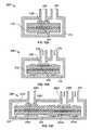
- FIGS. 1A and 1Bschematically illustrate a surface deformation EAP transducer employed as an actuator which utilizes polymer surface features to provide work output when the transducer is activated;
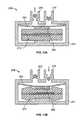
- FIGS. 2A and 2Bare cross-sectional views of exemplary constructs of an actuator of the present invention.
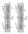
- FIGS. 3A-3Dillustrate various steps of a process for making electrical connections within the subject transducers for coupling to a printed circuit board (PCB) or flex connector;
- PCBprinted circuit board
- FIGS. 4A-4Dillustrate various steps of a process for making electrical connections within the subject transducers for coupling to an electrical wire
- FIG. 5is a cross-sectional view of a subject transducer having a piercing type of electrical contact
- FIGS. 6A and 6Bare top views of a thickness mode transducer and electrode pattern, respectively, for application in a button-type actuator;
- FIG. 7illustrates a top cutaway view of a keypad employing an array of button-type actuators of FIGS. 6A and 6B ;
- FIG. 8illustrates a top view of a thickness mode transducer for use in a novelty actuator in the form of a human hand
- FIG. 9illustrates a top view of thickness mode transducer in a continuous strip configuration
- FIG. 10illustrates a top view of a thickness mode transducer for application in a gasket-type actuator
- FIGS. 11A-11Dare cross-sectional views of touch screens employing various type gasket-type actuators
- FIGS. 12A-12Care cross-sectional views of passive and active states, respectively, of a poppet valve mechanism employing the thickness mode actuators of the present invention
- FIGS. 13A and 13Bare cross-sectional views of passive and active states, respectively, of a diaphragm-type fluid pump employing a thickness mode actuator of the present invention
- FIGS. 14A and 14Bare cross-sectional views of another diaphragm-type pump employing thickness mode actuators of the present invention with the pump undergoing exhaust and compression strokes, respectively;
- FIGS. 15A and 15Bare cross-sectional views of peristaltic pump embodiments employing thickness mode actuators of the present invention.
- FIGS. 16A and 16Bare cross-sectional views of a linear brake mechanism employing the thickness mode actuators of the present invention in passive and active modes, respectively;
- FIGS. 17A and 17Bare cross-sectional views of a rotary brake or clutch mechanism employing the thickness mode actuators of the present invention in passive and active modes, respectively;
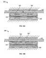
- FIGS. 18A and 18Bare cross-sectional views of another embodiment of a thickness mode transducer of the present invention in which the relative positions of the active and passive areas of the transducer are inversed from the above embodiments.
- EAP actuator 10for converting electrical energy to mechanical energy in accordance with one embodiment of the invention.
- Actuator 10includes EAP transducer 12 having a thin elastomeric dielectric polymer layer 14 and top and bottom electrodes 16 a , 16 b attached to the dielectric 14 on portions of its top and bottom surfaces, respectively.
- the portion of transducer 12 comprising the dielectric and at least two electrodesis referred to herein as an active area. Any of the transducers of the present invention may have one or more active areas.
- this actioncauses the compliant dielectric material outside the active area (i.e., the area covered by the electrodes), particularly perimetrically about, i.e., immediately around, the edges of the active area, to be displaced or bulge out-of-plane in the thickness direction (orthogonal to the plane defined by the transducer film).
- This bulgingproduces dielectric surface features 24 a - d . While out-of-plane surface features 24 are shown relatively local to the active area, the out-of-plane is not always localized as shown. In some cases, if the polymer is pre-strained, then the surface features 24 a - b are distributed over a surface area of the inactive portion of the dielectric material.
- an optional passive layermay be added to one or both sides of the transducer film structure where the passive layer covers all or a portion of the EAP film surface area.
- top and bottom passive layers 18 a , 18 bare attached to the top and bottom sides, respectively, of the EAP film 12 .
- Activation of the actuator and the resulting surface features of dielectric layer 12are amplified by the added thickness of passive layers 18 a , 18 b , as denoted by reference numbers 26 a - d in FIG. 1B .
- the EAP film 12may be configured such that the one or both electrodes 16 a , 16 b are depressed below the thickness of the dielectric layer. As such, the depressed electrode or portion thereof provides an electrode surface feature upon actuation of the EAP film 12 and the resulting deflection of dielectric material 14 . Electrodes 16 a , 16 c may be patterned or designed to produce customized transducer film surface features which may comprise polymer surface features, electrode surface features and/or passive layer surface features.
- one or more structures 20 a , 20 bare provided to facilitate coupling the work between the compliant passive slab and a rigid mechanical structure and directing the work output of the actuator.
- top structure 20 a(which may be in the form of a platform, bar, lever, rod, etc.) acts as an output member while bottom structure 20 b serves to couple actuator 10 to a fixed or rigid stricture 22 , such as ground.
- These output structuresneed not be discrete components but, rather, may be integrated or monolithic with the structure which the actuator is intended to drive.
- Structures 20 a , 20 balso serve to define the perimeter or shape of the surface features 26 a - d formed by the passive layers 18 a , 18 b .
- the collective actuator stackproduces an increase in thickness of the actuator's inactive portions, as shown in FIG. 1B , the net chance in height ⁇ h undergone by the actuator upon actuation is negative.
- the EAP transducers of the present inventionmay have any suitable construct to provide the desired thickness mode actuation.
- more than one EAP film layermay be used to fabricate the transducers for use in more complex applications, such as keyboard keys with integrated sensing capabilities where an additional EAP film layer may be employed as a capacitive sensor.
- FIG. 2Aillustrates such an actuator 30 employing a stacked transducer 32 having a double EAP film layer in accordance with the present invention.
- the double layerincludes two dielectric elastomer films with the top film 34 a sandwiched between top and bottom electrodes 34 b , 34 c , respectively, and the bottom film 36 a sandwiched between top and bottom electrodes 36 b , 36 c , respectively.
- Pairs of conductive traces or layersare provided to couple the electrodes to the high voltage and ground sides of a source of power (the latter not shown).
- the bus barsare positioned on the “inactive” portions of the respective EAP films (i.e., the portions in which the top and bottom electrodes do not overlap).
- Top and bottom bus bars 42 a , 42 bare positioned on the top and bottom sides, respectively, of dielectric layer 34 a
- top and bottom bus bars 44 a , 44 bpositioned on the top and bottom sides, respectively, of dielectric layer 36 a
- the top electrode 34 b of dielectric 34 a and the bottom electrode 36 c of dielectric 36 ai.e., the two outwardly facing electrodes, are commonly polarized by way of the mutual coupling of bus bars 42 a and 44 a through conductive elastomer via 68 a (shown in FIG. 2B ), the formation of which is described in greater detail below with respect to FIGS. 3A-3D .
- the bottom electrode 34 c of dielectric 34 a and the top electrode 36 b of dielectric 36 aare also commonly polarized by way of the mutual coupling of bus bars 42 b and 44 b through conductive elastomer via 68 b (shown in FIG. 2B ). Potting material 66 a , 66 b is used to seal via 68 a , 68 b .
- the opposing electrodes of each electrode pairare drawn together when a voltage is applied.
- the ground electrodesmay be placed on the outside of the stack so as to ground any piercing object before it reaches the high voltage electrodes, thus eliminating a shock hazard.
- the two EAP film layersmay be adhered together by film-to-film adhesive 40 b .
- the adhesive layermay optionally include a passive or slab layer to enhance performance.
- a top passive layer or slab 50 a and a bottom passive layer 50 bare adhered to the transducer structure by adhesive layer 40 a and by adhesive layer 40 c .
- Output bars 46 a , 46 bmay be coupled to top and bottom passive layers, respectively, by adhesive layers 48 a , 48 b , respectfully.
- the actuators of the present inventionmay employ any suitable number of transducer layers, where the number of layers may be even or odd. In the latter construct, one or more common ground electrode and bus bar may be used. Additionally, where safety is less of an issue, the high voltage electrodes may be positioned on the outside of the transducer stack to better accommodate a particular application.
- actuator 30must be electrically coupled to a source of power and control electronics (neither are shown). This may be accomplished by way of electrical tracing or wires on the actuator or on a PCB or a flex connector 62 which couples the high voltage and ground vias 68 a , 68 b to a power supply or an intermediate connection.
- Actuator 30may be packaged in a protective barrier material to seal it from humidity and environmental contaminants.
- the protective barrierincludes top and bottom covers 60 , 64 which are preferably sealed about PCB/flex connector 62 to protect the actuator from external forces and strains and/or environmental exposure.
- the protective barriermaybe impermeable to provide a hermetic seal.
- the coversmay have a somewhat rigid form to shield actuator 30 against physical damage or may be compliant to allow room for actuation displacement of the actuator 30 .
- the top cover 60is made of formed foil and the bottom cover 64 is made of a compliant foil, or vice versa, with the two covers then heat-sealed to board/connector 62 .
- Many other packaging materialssuch as metalized polymer films, PVDC, Aclar, styrenic or olefinic copolymers, polyesters and polyolefins can also be used.
- Compliant materialis used to cover the output structure or structures, here bar 46 b , which translate actuator output.
- FIGS. 3-5illustrate various methods of the present invention for forming the vias.
- the stacked transducer/actuator structure 70is laser drilled 80 through its entire thickness to PCB 72 to form the via holes 82 a , 82 b , as illustrated in FIG. 3B .
- the via holesare then filled by any suitable dispensing method, such as by injection, with a conductive material, e.g., carbon particles in silicone, as shown in FIG. 3C .
- a conductive materiale.g., carbon particles in silicone
- the conductively filled vias 84 a , 84 bare optionally potted 86 a , 86 b with any compatible non-conductive material, e.g., silicone, to electrically isolate the exposed end of the vias.
- a non-conductive tapemay be placed over the exposed vias.
- Standard electrical wiringmay be used in lieu of a PCB or flex connector to couple the actuator to the power supply and electronics.
- FIGS. 4A-4DVarious steps of forming the electrical vias and electrical connections to the power supply with such embodiments are illustrated in FIGS. 4A-4D with like components and steps to those in FIGS. 3A-3D having the same reference numbers.
- via holes 82 a , 82 bneed only be drilled to a depth within the actuator thickness to the extent that the bus bars 84 a , 84 b are reached.
- the via holesare then filled with conductive material, as shown in FIG. 4B , after which wire leads 88 a , 88 b are inserted into the deposited conductive material, as shown in FIG. 4C .
- the conductively filled vias and wire leadsmay then be potted over, as shown in FIG. 4D .
- FIG. 5illustrates another manner of providing conductive vias within the transducers of the present invention.
- Transducer 100has a dielectric film comprising a dielectric layer 104 having portions sandwiched between electrodes 106 a , 106 b , which in turn are sandwiched between passive polymer layers 110 a , 110 b .
- a conductive bus bar 108is provided on an inactive area of the EAP film.
- a conductive contact 114 having a piercing configurationis driven, either manually or otherwise, through one side of the transducer to a depth that penetrates the bus bar material 108 .
- a conductive trace 116extends along PCB/flex connector 112 from the exposed end of piercing contact 114 . This method of forming vias is particularly efficient as it eliminates the steps of drilling the via holes, rolling the via holes, placing a conductive wire in the via holes and potting the via holes.
- the thickness mode EAP transducers of the present inventionare usable in a variety of actuator applications with any suitable constrict and surface feature presentation.
- FIGS. 6-10illustrate exemplary thickness mode transducer/actuator applications.
- FIG. 6Aillustrates a thickness mode transducer 120 having a round construct which is ideal for button actuators for use in tactile or haptic feedback applications in which a user physically contacts a device, e.g., keyboards, touch screens, phones, etc.
- Transducer 120is formed from a thin elastomeric dielectric polymer layer 122 and top and bottom electrode patterns 124 a , 124 b (the bottom electrode pattern is shown in phantom), best shown in the isolated view in FIG. 6B .
- Each of the electrode patterns 124provides a stem portion 125 with a plurality of oppositely extending finger portions 127 forming a concentric pattern.
- the stems of the two electrodesare positioned diametrically to each other on opposite sides of the round dielectric layer 122 where their respective finger portions are in appositional alignment with each other to produce the pattern shown in FIG. 6A .
- the opposing electrode patterns in this embodimentare identical and symmetrical to each other, other embodiments are contemplated where the opposing electrode patterns are asymmetric, in shape and/or the amount of surface area which they occupy.
- the portions of the transducer material in which the two electrode materials do not overlapdefine the inactive portions 128 a , 128 b of the transducer.
- An electrical contact 126 a , 126 bis provided at the base of each of the two electrode stem portions for electrically coupling the transducer to a source of power and control electronics (neither are shown).
- the transducerWhen the transducer is activated, the opposing electrode fingers are drawn together, thereby compressing dielectric material 122 therebetween with the inactive portions 128 a , 128 b of the transducer bulging to form surface features about the perimeter of the button and/or internally to the button as desired.
- the button actuatormay be in the form of a single input or contact surface or may be provided in an array format having a plurality of contact surfaces.
- the button transducers of FIG. 6Aare ideal for use in keypad actuators 130 , as illustrated in FIG. 7 , for a variety of user interface devices, e.g., computer keyboards, phones, calculators, etc.
- Transducer array 132includes a top array 136 a of interconnected electrode patterns and bottom array 136 b (shown in phantom) of electrode patterns with the two arrays opposed with each other to produce the concentric transducer pattern of FIG. 6A with active and inactive portions as described.
- the keyboard structuremay be in the form of a passive layer 134 atop transducer array 132 .
- Passive layer 134may have its own surface features, such as key border 138 , which may be raised in the passive state to enable the user to tactilely align his/her fingers with the individual key pads, and/or further amplify the bulging of the perimeter of the respective buttons upon activation.
- key border 138When a key is pressed, the individual transducer upon which it lays is activated, causing the thickness mode bulging as described above, to provide the tactile sensation back to the user.
- Any number of transducersmay be provided in this manner and spaced apart to accommodate the type and size of keypad 134 being used. Examples of fabrication techniques for such transducer arrays are disclosed in U.S.
- the thickness mode transducers of the present inventionneed not be symmetrical and may take on any construct and shape.
- the subject transducersmay be used in any imaginable novelty application, such as the novelty hand device 140 illustrated in FIG. 8 .
- Dielectric material 142 in the form of a human handis provided having top and bottom electrode patterns 144 a , 144 b (the underside pattern being shown in phantom) in a similar hand shape.
- Each of the electrode patternsis electrically coupled to a bus bar 146 a , 146 b , respectively, which in turn is electrically coupled to a source of power and control electronics (neither are shown).
- the opposing electrode patternsare aligned with or atop each other rather than interposed, thereby creating alternating active and inactive areas.
- raised surface featuresare provided throughout the hand profile, i.e., on the inactive areas.
- the surface features in this exemplary applicationmay offer a visual feedback rather than a tactile-feedback. It is contemplated that the visual feedback may be enhanced by coloring, reflective material, etc.
- the transducer film of the present inventionmay be efficiently mass produced, particularly where the transducer electrode pattern is uniform or repeating, by commonly used web-based manufacturing techniques.
- the transducer film 150may be provided in a continuous strip format having continuous top and bottom electrical buses 156 a , 156 b deposited or formed on a strip of dielectric material 152 .
- the thickness mode featuresare defined by discrete (i.e., not continuous) but repeating active regions 158 formed by top and bottom electrode patterns 154 a , 154 b electrically coupled to the respective bus bars 156 a , 156 b the size, length, shape and pattern of which may be customized for the particular application.
- the active region(s)may be provided in a continuous pattern.
- the electrode and bus patternsmay be formed by known web-based manufacturing techniques, with the individual transducers then singulated, also by known techniques such as by cutting strip 150 along selected singulation lines 155 . It is noted that where the active regions are provided continuously along the strip, the strip is required to be cut with a high degree of precision to avoid shorting the electrodes. The cut ends of these electrodes may require potting or otherwise may be etched back to avoid tracking problems.
- the cut terminals of buses 156 a , 156 bare then coupled to sources of power/control to enable actuation of the resulting actuators.
- the strip or singulated strip portionsmay be stacked with any number of other transducer film strips/strip portions to provide a multi-layer stricture.
- the stacked structuremay then be laminated and mechanically coupled, if so desired, to rigid mechanical components of the actuator, such an output bar or the like.
- FIG. 10illustrates another variation of the subject transducers in which a transducer 160 formed by a strip of dielectric material 162 with top and bottom electrodes 164 a , 164 b on opposing sides of the strip arranged in a rectangular pattern thereby framing an open area 165 .
- Each of the electrodesterminates in an electrical bus 166 a , 166 b , respectively, having an electrical contact point 168 a , 168 b for coupling to a source of power and control electronics (neither being shown).
- a passive layer(not shown) that extends across the enclosed area 165 may be employed on either side of the transducer film, thereby forming a gasket configuration, for both environmental protection and mechanical coupling of the output bars (also not shown).
- the gasket actuatorneed not be a continuous, single actuator.
- One or more discrete actuatorscan also be used to line the perimeter of an area which may be optionally sealed with non-active compliant gasket material
- FIGS. 11A-11Dare cross-sectional views of touch screens employing variations of a thickness mode actuator of the present invention with like reference numbers referencing similar components amongst the four figures.
- the touch screen device 170may include a touch sensor plate 174 , typically made of a glass or plastic material, and, optionally, a liquid crystal display (LCD) 172 .
- the twoare stacked together and spaced apart by EAP thickness mode actuator 180 defining an open space 176 therebetween.
- the collective stacked structureis held together by frame 178 .
- Actuator 180includes the transducer film formed by dielectric film layer 182 sandwiched centrally by electrode pair 184 a , 184 b .
- the transducer filmis in turn sandwiched between top and bottom passive layers 186 a , 186 b and further held between a pair of output structures 188 a , 188 b which are mechanically coupled to touch plate 174 and LCD 172 , respectively.
- the right side of FIG. 11Ashows the relative position of the LCD and touch plate when the actuator is inactive, while the left side of FIG. 11A shows the relative positions of the components when the actuator is active, i.e., upon a user depressing touch plate 174 in the direction of arrow 175 .
- the electrodes 184 a , 184 bare drawn together thereby compressing the portion of dielectric film 182 therebetween while creating surface features in the dielectric material and passive layers 186 a , 186 b outside the active area, which surface features are further enhanced by the compressive force caused by output blocks 188 a , 188 b .
- the surface featuresprovide a slight force on touch plate 174 in the direction opposite arrow 175 which gives the user a tactile sensation in response to depressing the touch plate.
- Touch screen device 190 of FIG. 11Dhas a similar construct to that of FIG. 11A with the difference being that LCD 172 wholly resides within the internal area framed by the rectangular (or square, etc.) shaped thickness mode actuator 180 .
- the spacing 176 between LCD 172 and touch plate 174 when the device is in an inactive stateis significantly less than in the embodiment of FIG. 11A , thereby providing a lower profile design.
- the bottom output structure 188 b of the actuatorrests directly on the back wall 178 ′ of frame 178 .
- device 190functions similarly to device 170 in that the actuator surface features provide a slight tactile force in the direction opposite arrow 185 in response to depressing the touch plate.
- the two touch screen devices just describedare single phase devices as they function in a single direction.
- Two (or more) of the subject gasket-type actuatorsmay be used in tandem to produce a two phase (bidirectional) touch screen device 200 as in FIG. 11C .
- the construct of device 200is similar to that of the device of FIG. 11B but with the addition of a second thickness mode actuator 180 ′ which sits atop touch plate 174 .
- the two actuators and touch plate 174are held in stacked relation by way of frame 178 which has an added inwardly extending top shoulder 178 ′′.
- touch plate 174is sandwiched directly between the innermost output blocks 188 a , 188 b ′ of actuators 180 , 180 ′, respectively, while the outermost output blocks 188 b , 188 a ′ of actuators 180 ′, respectively, buttress the frame members 178 ′ and 178 ′′, respectively.
- This enclosed gasket arrangementkeeps dust and debris out of the optical path within space 176 .
- the left side of the figureillustrates bottom actuator 180 in an active state and top actuator 180 ′ in a passive state in which sensor plate 174 is caused to move towards LCD 172 in the direction of arrow 195 .
- the right side of the figureillustrates bottom actuator 180 in a passive state and top actuator 180 ′ in an active state in which sensor plate 174 is caused to move away from LCD 172 in the direction of arrow 195 ′.
- FIG. 11Dillustrates another two phase touch sensor device 210 but with a pair of thickness mode strip actuators 180 oriented with the electrodes orthogonal to the touch sensor plate.
- the two phase or bi-directional movement of touch plate 174is in-plane as indicated by arrow 205 .
- the actuator 180is positioned such that the plane of its EAP film is orthogonal to those of LCD 172 and touch plate 174 .
- actuator 180is held between the sidewall 202 of frame 178 and an inner frame member 206 upon which rests touch plate 174 .
- inner frame member 206is affixed to the output block 188 a of actuator 180 , it and touch plate 174 are “floating” relative to outer frame 178 to allow for the in-plane or lateral motion.
- This constructprovides a relatively compact, low-profile design as it eliminates the added clearance that would otherwise be necessary for two-phase out-of-plane motion by touch plate 174 .
- the two actuatorswork in opposition for two-phase motion.
- the combined assembly of plate 174 and brackets 206keep the actuator strips 180 in slight compression against the sidewall 202 of frame 178 . When one actuator is active, it compresses or thins further while the other actuator expands due to the stored compressive force. This moves the plate assembly toward the active actuator. The plate moves in the opposite direction by deactivating the first actuator and activating the second actuator.
- FIGS. 12A and 12Bshow a one-way poppet valve mechanism 220 employing thickness mode actuator 232 .
- the actuatoris seated within fluid chamber 234 having fluid inlet and outlet ports 236 , 238 , respectively.
- Actuator 232is situation within chamber 234 such that its output structure 240 is aligned with outlet port 238 .
- output structure 240is buttressed against aperture 238 ′ of the outlet port which defines the valve seat.
- the valvehas a normally closed configuration.
- the thickness mode operation of the actuator 232when activated pulls output structure 240 away from valve seat 238 ′ thereby allowing fluid within chamber 234 to exit through outlet port 238 .
- FIG. 12Cillustrates a two-way poppet valve 250 having fluid chamber 254 with an inlet port 256 and two output ports 258 a , 258 b having respective apertures 258 a ′, 258 b ′.
- An actuator mechanism 252 contained within the chamberincludes two activatable portions 252 a , 252 b , each having an output structure 260 a , 260 b , respectively, aligned with output ports 258 a , 258 b , respectively.
- actuator portion 252 ais active while actuator portion 252 b is inactive, thereby alternating fluid flow through the two outlet ports.
- both actuator portionsmay be activated in tandem, if desired.
- valve 250may have any number of outlet port-actuator pairings with actuation function being accomplished with either a monolithic structure with a plurality of activatable portions, as illustrated, or a plurality of structurally discrete actuators.
- the individual actuators or actuator portionsmay be activated in tandem or independently, such that any combination of output flow is provided.
- the subject actuatorsare also suitable for use with diaphragm type pumps.
- One such diaphragm pump 270is shown in FIGS. 13A and 13B in which the fluid chamber 274 has inlet and outlet ports 276 , 278 , respectively, having check valves mechanisms to control fluid flow therethrough.
- the output structure 280 of thickness mode actuator 272is affixed to the underside of a diaphragm 282 that extends between the sidewalls and across the upper end of chamber 274 .
- the diaphragmis made of a material stiff enough to not flex or stretch under compression pressure, e.g., fiber reinforced rubbers, stiff elastomers, filled silicone, a thin metal membrane, etc.
- Activating and deactivating actuator 272moves diaphragm 282 away and towards, respectively, the inlet and outlet ports.
- outlet check valve 278With the positive pressure created in chamber 274 when diaphragm 274 is moved towards the ports, as illustrated in FIG. 13A , outlet check valve 278 is caused to open allow fluid to be exhausted from the chamber. Conversely, with the negative pressure created in chamber 274 when diaphragm 274 is moved away from the ports, as illustrated in FIG. 13B , inlet check valve 278 is caused to open, creating fluid intake to the chamber.
- FIGS. 14A and 14Billustrate another diaphragm-type pump employing thickness mode a multi-actuator mechanism 276 .
- the actuatorhas three activatable portions 276 a - c (but may have more or fewer portions), with the outer two portions 276 a , 276 c being aligned relative to inlet-outlet ports 274 a , 274 b , respectively, of fluid chamber 292 .
- Diaphragm 298is coupled at its underside to the respective output structures 300 a - c of the actuator portions.
- To exhaust fluid from chamber 292one or both ports 294 a , 294 b are opened, as illustrated in FIG. 14A , by activating outer actuators 296 a , 296 c .
- Diaphragm sheet 298may employ multiple materials so as to facilitate the poppet valve sealing, for example, the membrane could be made of a metal foil with rubber coating over the valve area.
- Pump 310comprises a chamber or conduit (which may have any suitable cross-sectional shape, e.g., cylindrical, rectangular, square, etc.) having a base 312 a and a top portion or cover 312 b .
- Thickness mode actuator mechanism 318here having four activatable portions illustrated, is offset from base 312 a by output or mounting structures 314 a .
- the opposing output structures 314 bare coupled to the underside of diaphragm 316 .
- the spacing provided by the offset of the structures 314 a , 314 ballow for the thickness mode bulging of the inactive portions and the compressing of the active portions of the actuator strip 318 .
- Fluidis caused to linearly move between diaphragm 316 and top cover 312 b by sequential activation and deactivation of the various active portions of actuator 318 .
- the flow ratemay be varied by controlling the on-off rate of the active portions.
- a fixed diaphragm 322may be mounted to the underside of top cover 312 b to facilitate fluid flow dynamics through the passageway 320 defined between the two diaphragms or to provide a disposable fluid path (with the actuator and housing being non-disposable).
- FIG. 15Billustrates another peristaltic pump 330 with a simplified design in that the diaphragm(s) and top output structures of the peristaltic pump of FIG. 15A have been eliminated.
- the top passive layer 324 of actuator 318takes the function of previous diaphragm 316 , with fluid passing through the spacing 326 between the passive layer and the top cover or 312 b.
- FIGS. 16A and 16Billustrate a proportional linear braking system 330 in which a moveable member 332 (such as those used for commonly known rod bearing arrangement) is linearly translatable within the spacing between a grounded structure 338 and a brake mechanism 334 .
- the brakeincludes thickness mode actuator mechanism 336 positioned within housing 334 , which is also grounded.
- Actuator 336may have one or more active areas (i.e., two active areas are employed here) depending on the surface area of member 332 and the breaking force required to stop its movement. For maximum breaking force (as well as for maximum clearance), all of the active areas are activated/deactivated simultaneously. In the passive state, as illustrated in FIG.
- the output plate 342 of the actuatorsis in a closed or extended position, thereby clamping member 332 against grounding pad 338 .
- output plate 342is open or receded within housing 334 , providing clearance for the linear movement of member 332 .
- FIGS. 17A and 17Billustrate a rotary braking system 350 having a rotary disc 352 having a disc element 352 a and an axial shaft 352 b .
- the braking actuators 356 a , 356 bare mounted in stacked relationship within a housing 354 .
- Disc 352is positioned within the spacing between inwardly facing output members or braking or clutch pads 358 a , 35 b , respectively.
- actuators 356 a , 356 bare inactive and in their highest profile, as illustrated in FIG. 17A , they are caused to clamp down and stop the rotation of disc 352 .
- the actuatorsWhen the actuators are active and in a compressed state, disc 352 is unclamped and allowed to move therethrough.
- the amount of braking force applied to disc 352 acan be proportioned by either activating one of the two actuators or activating them both in tandem but at a decreased voltage to reduce their respective output displacement.
- the transducer/actuator embodiments described thus farhave the passive layer(s) coupled to both the active (i.e., areas including overlapping electrodes) and inactive regions of the EAP transducer film.
- the transducer/actuatorhas also employed a rigid output structure, that structure has been positioned over areas of the passive layers that reside above the active regions.
- the active/activatable regions of these embodimentshave been positioned centrally relative to the inactive regions.
- the present inventionalso includes other transducer/actuator configurations.
- the passive layer(s)may cover only the active regions or only the inactive regions.
- the inactive regions of the EAP filmmay be positioned centrally to the active regions.
- FIGS. 18A and 18Billustrate one such variation in which the inactive area is positioned internally or centrally to the active region(s), i.e., the central portion of the EAP film is devoid of overlapping electrodes.
- Thickness mode actuator 360includes EAP transducer film comprising dielectric layer 362 sandwiched between electrode layers 364 a , 364 b in which a central portion 365 of the film is passive and devoid of electrode material.
- the EAP filmis held in a taut or stretched condition by at least one of top and bottom frame members 366 a , 366 b , collectively providing a cartridge configuration.
- passive layers 368 a , 368 bCovering at least one of the top and bottom sides of the passive portion 365 of the film are passive layers 368 a , 368 b with optional rigid constraints or output members 370 a , 370 b mounted thereon, respectively.
- the compression of the EAP filmcauses the film material to retract inward, as shown by arrows 367 a , 367 b , rather than outward as with the above-described actuator embodiments.
- the compressed EAP filmimpinges on the passive material 368 a , 368 b causing its diameter to decrease and its height to increase.
- the passively coupled film actuatorsmay be provided in multiples in stacked or planar relationships to provide multi-phase actuation and/or to increase the output force and/or stroke of the actuator.
- the actuatormay be used as a key or button device and may be stacked or integrated with sensor devices such as membrane switches.
- the bottom output member or bottom electrodecan be used to provide sufficient pressure to a membrane switch to complete the circuit or can complete the circuit directly if the bottom output member has a conductive layer. Multiple actuators can be used in arrays for applications such as keypads or keyboards.
- the various dielectric elastomer and electrode materials disclosed in U.S. Patent Application Publication No. 2005/0157893are suitable for use with the thickness mode transducers of the present invention.
- the dielectric elastomersinclude any substantially insulating, compliant polymer, such as silicone rubber and acrylic, that deforms in response to an electrostatic force or whose deformation results in a change in electric field.
- the optimal material, physical, and chemical propertiescan be tailored by judicious selection of monomer (including any side chains), additives, degree of cross-linking, crystallinity, molecular weight, etc.
- Electrodes described therein and suitable for useinclude structured electrodes comprising metal traces and charge distribution layers, textured electrodes, conductive greases such as carbon greases or silver greases, colloidal suspensions, high aspect ratio conductive materials such as conductive carbon black, carbon fibrils, carbon nanotubes, graphene and metal nanowires, and mixtures of ionically conductive materials.
- the electrodesmay be made of a compliant material such as elastomer matrix containing carbon or other conductive particles.
- the present inventionmay also employ metal and semi-inflexible electrodes.
- Exemplary passive layer materials for use in the subject transducersinclude but are not limited to silicone, styrenic or olefinic copolymer, polyurethane, acrylate, rubber, a soft polymer, a soft elastomer (gel), soft polymer foam, or a polymer/gel hybrid, for example.
- the relative elasticity and thickness of the passive layer(s) and dielectric layerare selected to achieve a desired output (e.g., the net thickness or thinness of the intended surface features), where that output response may be designed to be linear (e.g., the passive layer thickness is amplified proportionally to the that of the dielectric layer when activated) or non-linear (e.g., the passive and dielectric layers get thinner or thicker at varying rates).
- the subject methodsmay include each of the mechanical and/or activities associated with use of the devices described. As such, methodology implicit to the use of the devices described forms part of the invention. Other methods may focus on fabrication of such devices.
- any optional feature of the inventive variations describedmay be set forth and claimed independently, or in combination with any one or more of the features described herein.
- Reference to a singular itemincludes the possibility that there are plural of the same items present. More specifically, as used herein and in the appended claims, tile singular forms “a,” “an,” “said,” and “the” include plural referents unless the specifically stated otherwise. In other words, use of the articles allow for “at least one” of the subject item in the description above as well as the claims below. It is further noted that claims may be drafted to exclude any optional element.
Landscapes
- Engineering & Computer Science (AREA)
- General Engineering & Computer Science (AREA)
- Theoretical Computer Science (AREA)
- Physics & Mathematics (AREA)
- Human Computer Interaction (AREA)
- General Physics & Mathematics (AREA)
- Manufacturing & Machinery (AREA)
- Spectroscopy & Molecular Physics (AREA)
- General Electrical Machinery Utilizing Piezoelectricity, Electrostriction Or Magnetostriction (AREA)
- Push-Button Switches (AREA)
- Position Input By Displaying (AREA)
- Laminated Bodies (AREA)
- Micromachines (AREA)
Abstract
Description
Claims (12)
Priority Applications (10)
| Application Number | Priority Date | Filing Date | Title |
|---|---|---|---|
| US12/358,142US8222799B2 (en) | 2008-11-05 | 2009-01-22 | Surface deformation electroactive polymer transducers |
| EP09825433.7AEP2347459B1 (en) | 2008-11-05 | 2009-11-05 | Surface deformation electroactive polymer transducers |
| KR1020117010238AKR20110097764A (en) | 2008-11-05 | 2009-11-05 | Surface Deformed Electroactive Polymer Transducer |
| CA2742410ACA2742410A1 (en) | 2008-11-05 | 2009-11-05 | Surface deformation electroactive polymer transducers |
| MX2011004695AMX2011004695A (en) | 2008-11-05 | 2009-11-05 | Surface deformation electroactive polymer transducers. |
| PCT/US2009/063441WO2010054115A1 (en) | 2008-11-05 | 2009-11-05 | Surface deformation electroactive polymer transducers |
| TW098137649ATWI527070B (en) | 2008-11-05 | 2009-11-05 | Transducer, transducer assembly and method of fabricating a transducer |
| KR1020147014204AKR101535045B1 (en) | 2008-11-05 | 2009-11-05 | Surface deformation electroactive polymer transducers |
| CN2009801543356ACN102272959A (en) | 2008-11-05 | 2009-11-05 | Surface deformation electroactive polymer transducer |
| JP2011535671AJP5684713B2 (en) | 2008-11-05 | 2009-11-05 | Surface deformation electroactive polymer converter |
Applications Claiming Priority (2)
| Application Number | Priority Date | Filing Date | Title |
|---|---|---|---|
| US11164808P | 2008-11-05 | 2008-11-05 | |
| US12/358,142US8222799B2 (en) | 2008-11-05 | 2009-01-22 | Surface deformation electroactive polymer transducers |
Publications (2)
| Publication Number | Publication Date |
|---|---|
| US20100109486A1 US20100109486A1 (en) | 2010-05-06 |
| US8222799B2true US8222799B2 (en) | 2012-07-17 |
Family
ID=42130526
Family Applications (1)
| Application Number | Title | Priority Date | Filing Date |
|---|---|---|---|
| US12/358,142Active2030-02-12US8222799B2 (en) | 2008-11-05 | 2009-01-22 | Surface deformation electroactive polymer transducers |
Country Status (9)
| Country | Link |
|---|---|
| US (1) | US8222799B2 (en) |
| EP (1) | EP2347459B1 (en) |
| JP (1) | JP5684713B2 (en) |
| KR (2) | KR101535045B1 (en) |
| CN (1) | CN102272959A (en) |
| CA (1) | CA2742410A1 (en) |
| MX (1) | MX2011004695A (en) |
| TW (1) | TWI527070B (en) |
| WO (1) | WO2010054115A1 (en) |
Cited By (78)
| Publication number | Priority date | Publication date | Assignee | Title |
|---|---|---|---|---|
| US20120154133A1 (en)* | 2010-12-21 | 2012-06-21 | Electronics And Telecommunications Research Institute | Haptic feedback case for electronic equipment |
| US20140076063A1 (en)* | 2012-09-17 | 2014-03-20 | Tk Holdings Inc. | Single layer force sensor |
| WO2014066576A1 (en) | 2012-10-24 | 2014-05-01 | Bayer Intellectual Property Gmbh | Polymer diode |
| WO2014089388A2 (en) | 2012-12-07 | 2014-06-12 | Bayer Materialscience Ag | Electroactive polymer actuated aperture |
| WO2014117125A1 (en) | 2013-01-28 | 2014-07-31 | Bayer Materialscience Llc | Electroactive polymer actuators and feedback system therefor |
| US8847890B2 (en) | 2011-01-04 | 2014-09-30 | Synaptics Incorporated | Leveled touchsurface with planar translational responsiveness to vertical travel |
| WO2014160757A2 (en) | 2013-03-26 | 2014-10-02 | Bayer Materialscience Ag | Independent tunig of audio devices employing electroactive polymer actuators |
| WO2015020698A2 (en) | 2013-03-15 | 2015-02-12 | Bayer Materialscience Ag | Electroactive polymer actuated air flow thermal management module |
| CN104613303A (en)* | 2015-01-16 | 2015-05-13 | 西北工业大学 | Controllable out-of-plane deformation unit based on electric active soft matter |
| US9040851B2 (en) | 2012-08-06 | 2015-05-26 | Synaptics Incorporated | Keycap assembly with an interactive spring mechanism |
| US9053617B2 (en) | 2012-11-21 | 2015-06-09 | Novasentis, Inc. | Systems including electromechanical polymer sensors and actuators |
| US9164586B2 (en)* | 2012-11-21 | 2015-10-20 | Novasentis, Inc. | Haptic system with localized response |
| US9170650B2 (en) | 2012-11-21 | 2015-10-27 | Novasentis, Inc. | EMP actuators for deformable surface and keyboard application |
| US9177733B2 (en) | 2012-08-06 | 2015-11-03 | Synaptics Incorporated | Touchsurface assemblies with linkages |
| US9183710B2 (en) | 2012-08-03 | 2015-11-10 | Novasentis, Inc. | Localized multimodal electromechanical polymer transducers |
| US9195058B2 (en) | 2011-03-22 | 2015-11-24 | Parker-Hannifin Corporation | Electroactive polymer actuator lenticular system |
| US9213372B2 (en) | 2013-04-19 | 2015-12-15 | Synaptics Incorporated | Retractable keyboard keys |
| US9218927B2 (en) | 2012-08-06 | 2015-12-22 | Synaptics Incorporated | Touchsurface assembly with level and planar translational responsiveness via a buckling elastic component |
| US9224554B2 (en) | 2013-03-14 | 2015-12-29 | Synaptics Incorporated | Anti-tilt and rotation techniques for a touchsurface assembly having translating keys |
| US9231186B2 (en) | 2009-04-11 | 2016-01-05 | Parker-Hannifin Corporation | Electro-switchable polymer film assembly and use thereof |
| US9269885B2 (en) | 2012-11-21 | 2016-02-23 | Novasentis, Inc. | Method and localized haptic response system provided on an interior-facing surface of a housing of an electronic device |
| US20160091099A1 (en)* | 2014-09-30 | 2016-03-31 | Buerkert Werke Gmbh | Diaphragm valve |
| US9324515B2 (en) | 2012-08-06 | 2016-04-26 | Synaptics Incorporated | Touchsurface assembly utilizing magnetically enabled hinge |
| US9357312B2 (en) | 2012-11-21 | 2016-05-31 | Novasentis, Inc. | System of audio speakers implemented using EMP actuators |
| US9351900B2 (en) | 2012-09-17 | 2016-05-31 | President And Fellows Of Harvard College | Soft exosuit for assistance with human motion |
| US9370640B2 (en) | 2007-09-12 | 2016-06-21 | Novasentis, Inc. | Steerable medical guide wire device |
| US9425383B2 (en) | 2007-06-29 | 2016-08-23 | Parker-Hannifin Corporation | Method of manufacturing electroactive polymer transducers for sensory feedback applications |
| US9430050B2 (en) | 2011-01-04 | 2016-08-30 | Synaptics Incorporated | Touchsurface with level and planar translational travel responsiveness |
| US9507468B2 (en) | 2013-08-30 | 2016-11-29 | Novasentis, Inc. | Electromechanical polymer-based sensor |
| US9535534B2 (en) | 2013-03-14 | 2017-01-03 | Lenovo (Beijing) Co., Ltd. | Electronic device and control method |
| US20170008615A1 (en)* | 2015-07-06 | 2017-01-12 | California Institute Of Technology | Flow control technique by dielectric materials |
| US9553254B2 (en) | 2011-03-01 | 2017-01-24 | Parker-Hannifin Corporation | Automated manufacturing processes for producing deformable polymer devices and films |
| US9576446B2 (en) | 2014-08-07 | 2017-02-21 | Novasentis, Inc. | Ultra-thin haptic switch with lighting |
| US20170059419A1 (en)* | 2015-09-02 | 2017-03-02 | Korea Advanced Institute Of Science And Technology | Piezocapacitive type pressure sensor with porous dielectric layer |
| US9652946B2 (en) | 2014-05-02 | 2017-05-16 | Novasentis, Inc. | Hands-free, wearable vibration devices and method |
| US9666391B2 (en) | 2013-10-22 | 2017-05-30 | Novasentis, Inc. | Retractable snap domes |
| US9705068B2 (en) | 2012-06-19 | 2017-07-11 | Novasentis, Inc. | Ultra-thin inertial actuator |
| US9727031B2 (en) | 2012-04-13 | 2017-08-08 | Tk Holdings Inc. | Pressure sensor including a pressure sensitive material for use with control systems and methods of using the same |
| US9761790B2 (en) | 2012-06-18 | 2017-09-12 | Parker-Hannifin Corporation | Stretch frame for stretching process |
| US20170261215A1 (en)* | 2014-09-15 | 2017-09-14 | Samsung Electronics Co., Ltd. | Air current changeable full front blowing type air conditioner |
| US9829980B2 (en) | 2013-10-08 | 2017-11-28 | Tk Holdings Inc. | Self-calibrating tactile haptic muti-touch, multifunction switch panel |
| US9833596B2 (en) | 2013-08-30 | 2017-12-05 | Novasentis, Inc. | Catheter having a steerable tip |
| US9876160B2 (en) | 2012-03-21 | 2018-01-23 | Parker-Hannifin Corporation | Roll-to-roll manufacturing processes for producing self-healing electroactive polymer devices |
| CN107848440A (en)* | 2015-07-31 | 2018-03-27 | 大陆泰密克微电子有限责任公司 | Device for pneumatically adjusting a seat in a vehicle |
| US9972768B2 (en) | 2014-08-15 | 2018-05-15 | Novasentis, Inc. | Actuator structure and method |
| US10067567B2 (en) | 2013-05-30 | 2018-09-04 | Joyson Safety Systems Acquistion LLC | Multi-dimensional trackpad |
| US10088936B2 (en) | 2013-01-07 | 2018-10-02 | Novasentis, Inc. | Thin profile user interface device and method providing localized haptic response |
| US10125758B2 (en) | 2013-08-30 | 2018-11-13 | Novasentis, Inc. | Electromechanical polymer pumps |
| US10278883B2 (en) | 2014-02-05 | 2019-05-07 | President And Fellows Of Harvard College | Systems, methods, and devices for assisting walking for developmentally-delayed toddlers |
| US10353131B2 (en) | 2016-04-14 | 2019-07-16 | Boe Technology Group Co., Ltd. | Device, system, backlight module and test method for simulating light guide plate |
| US10434030B2 (en) | 2014-09-19 | 2019-10-08 | President And Fellows Of Harvard College | Soft exosuit for assistance with human motion |
| US10466826B2 (en) | 2014-10-08 | 2019-11-05 | Joyson Safety Systems Acquisition Llc | Systems and methods for illuminating a track pad system |
| US20200132223A1 (en)* | 2018-10-24 | 2020-04-30 | Toyota Motor Engineering & Manufacturing North America, Inc. | Self-healing microvalve |
| US10749448B2 (en)* | 2018-11-30 | 2020-08-18 | Facebook Technologies, Llc | Engineered loading response in electroactive polymer devices having structured nanovoids |
| US10843332B2 (en) | 2013-05-31 | 2020-11-24 | President And Fellow Of Harvard College | Soft exosuit for assistance with human motion |
| US10859101B2 (en) | 2018-12-10 | 2020-12-08 | Toyota Motor Engineering & Manufacturing North America, Inc. | Soft-bodied actuator with pinched configuration |
| US10864100B2 (en) | 2014-04-10 | 2020-12-15 | President And Fellows Of Harvard College | Orthopedic device including protruding members |
| US10946535B2 (en) | 2018-10-25 | 2021-03-16 | Toyota Motor Engineering & Manufacturing North America, Inc. | Earthworm-like motion of soft bodied structure |
| US11014804B2 (en) | 2017-03-14 | 2021-05-25 | President And Fellows Of Harvard College | Systems and methods for fabricating 3D soft microstructures |
| US11036297B2 (en) | 2018-07-12 | 2021-06-15 | Korea Institute Of Science And Technology | Tactile feedback device |
| US11041576B2 (en) | 2018-10-25 | 2021-06-22 | Toyota Motor Engineering & Manufacturing North America, Inc. | Actuator with static activated position |
| US11066016B2 (en) | 2018-12-18 | 2021-07-20 | Toyota Motor Engineering & Manufacturing North America, Inc. | Adjusting vehicle mirrors |
| US11081975B2 (en) | 2018-10-25 | 2021-08-03 | Toyota Motor Engineering & Manufacturing North America, Inc. | Somersaulting motion of soft bodied structure |
| US11088635B2 (en) | 2018-10-25 | 2021-08-10 | Toyota Motor Engineering & Manufacturing North America, Inc. | Actuator with sealable edge region |
| US20210246993A1 (en)* | 2020-02-11 | 2021-08-12 | Buerkert Werke Gmbh & Co. Kg | Valve Actuator and Valve |
| EP3719988A4 (en)* | 2017-11-28 | 2021-08-25 | Zeon Corporation | DIELECTRIC ELASTOMER DRIVE SENSOR SYSTEM AND LAYER |
| US11195506B2 (en) | 2018-12-03 | 2021-12-07 | Toyota Motor Engineering & Manufacturing North America, Inc. | Sound-modulating windows |
| US11324655B2 (en) | 2013-12-09 | 2022-05-10 | Trustees Of Boston University | Assistive flexible suits, flexible suit systems, and methods for making and control thereof to assist human mobility |
| US11422629B2 (en) | 2019-12-30 | 2022-08-23 | Joyson Safety Systems Acquisition Llc | Systems and methods for intelligent waveform interruption |
| US11473567B2 (en) | 2019-02-07 | 2022-10-18 | Toyota Motor Engineering & Manufacturing North America, Inc. | Programmable surface |
| US11479308B2 (en) | 2019-01-09 | 2022-10-25 | Toyota Motor Engineering & Manufacturing North America, Inc. | Active vehicle interface for crosswind management |
| US11498203B2 (en) | 2016-07-22 | 2022-11-15 | President And Fellows Of Harvard College | Controls optimization for wearable systems |
| US11498270B2 (en) | 2018-11-21 | 2022-11-15 | Toyota Motor Engineering & Manufacturing North America, Inc. | Programmable matter |
| US11548261B2 (en) | 2018-10-24 | 2023-01-10 | Toyota Motor Engineering & Manufacturing North America, Inc. | Structure with selectively variable stiffness |
| US11590046B2 (en) | 2016-03-13 | 2023-02-28 | President And Fellows Of Harvard College | Flexible members for anchoring to the body |
| US11598331B2 (en) | 2021-02-24 | 2023-03-07 | Toyota Motor Engineering & Manufacturing North America, Inc. | Electroactive polymer actuator for multi-stage pump |
| US11706992B2 (en) | 2019-01-02 | 2023-07-18 | Fuzhou Boe Optoelectronics Technology Co., Ltd. | Flexible body and method for controlling flexible body to deform |
| US20240077370A1 (en)* | 2021-01-11 | 2024-03-07 | Innovationlab Gmbh | Sensor Device |
Families Citing this family (106)
| Publication number | Priority date | Publication date | Assignee | Title |
|---|---|---|---|---|
| US8154527B2 (en) | 2008-01-04 | 2012-04-10 | Tactus Technology | User interface system |
| US9423875B2 (en) | 2008-01-04 | 2016-08-23 | Tactus Technology, Inc. | Dynamic tactile interface with exhibiting optical dispersion characteristics |
| US9588683B2 (en) | 2008-01-04 | 2017-03-07 | Tactus Technology, Inc. | Dynamic tactile interface |
| US8704790B2 (en) | 2010-10-20 | 2014-04-22 | Tactus Technology, Inc. | User interface system |
| US9128525B2 (en) | 2008-01-04 | 2015-09-08 | Tactus Technology, Inc. | Dynamic tactile interface |
| US8547339B2 (en) | 2008-01-04 | 2013-10-01 | Tactus Technology, Inc. | System and methods for raised touch screens |
| US9612659B2 (en) | 2008-01-04 | 2017-04-04 | Tactus Technology, Inc. | User interface system |
| US8922510B2 (en) | 2008-01-04 | 2014-12-30 | Tactus Technology, Inc. | User interface system |
| US9552065B2 (en) | 2008-01-04 | 2017-01-24 | Tactus Technology, Inc. | Dynamic tactile interface |
| US8553005B2 (en) | 2008-01-04 | 2013-10-08 | Tactus Technology, Inc. | User interface system |
| US9274612B2 (en) | 2008-01-04 | 2016-03-01 | Tactus Technology, Inc. | User interface system |
| US8570295B2 (en) | 2008-01-04 | 2013-10-29 | Tactus Technology, Inc. | User interface system |
| US9298261B2 (en) | 2008-01-04 | 2016-03-29 | Tactus Technology, Inc. | Method for actuating a tactile interface layer |
| US9430074B2 (en) | 2008-01-04 | 2016-08-30 | Tactus Technology, Inc. | Dynamic tactile interface |
| US9557915B2 (en) | 2008-01-04 | 2017-01-31 | Tactus Technology, Inc. | Dynamic tactile interface |
| US8243038B2 (en) | 2009-07-03 | 2012-08-14 | Tactus Technologies | Method for adjusting the user interface of a device |
| US9720501B2 (en) | 2008-01-04 | 2017-08-01 | Tactus Technology, Inc. | Dynamic tactile interface |
| US8947383B2 (en) | 2008-01-04 | 2015-02-03 | Tactus Technology, Inc. | User interface system and method |
| US8456438B2 (en) | 2008-01-04 | 2013-06-04 | Tactus Technology, Inc. | User interface system |
| US20160187981A1 (en) | 2008-01-04 | 2016-06-30 | Tactus Technology, Inc. | Manual fluid actuator |
| US9063627B2 (en) | 2008-01-04 | 2015-06-23 | Tactus Technology, Inc. | User interface and methods |
| US9052790B2 (en) | 2008-01-04 | 2015-06-09 | Tactus Technology, Inc. | User interface and methods |
| US9588684B2 (en) | 2009-01-05 | 2017-03-07 | Tactus Technology, Inc. | Tactile interface for a computing device |
| US8760413B2 (en)* | 2009-01-08 | 2014-06-24 | Synaptics Incorporated | Tactile surface |
| US8915151B2 (en)* | 2009-06-05 | 2014-12-23 | Sungkyunkwan University Foundation For Corporate Collaboration | Active skin for conformable tactile interface |
| CN101923417B (en)* | 2009-06-10 | 2013-06-05 | 鸿富锦精密工业(深圳)有限公司 | Touch type input device |
| WO2011003113A1 (en) | 2009-07-03 | 2011-01-06 | Tactus Technology | User interface enhancement system |
| US10164135B2 (en)* | 2009-08-07 | 2018-12-25 | Guardian Glass, LLC | Electronic device including graphene-based layer(s), and/or method or making the same |
| US8569935B1 (en)* | 2009-09-14 | 2013-10-29 | Tomasz Andrzej Kosierkiewicz | Piezoelectric shoe insert |
| US8624839B2 (en) | 2009-10-15 | 2014-01-07 | Synaptics Incorporated | Support-surface apparatus to impart tactile feedback |
| US10068728B2 (en) | 2009-10-15 | 2018-09-04 | Synaptics Incorporated | Touchpad with capacitive force sensing |
| KR101113897B1 (en) | 2009-12-07 | 2012-02-29 | 한국과학기술원 | Solenoid System Using Spiral Transparant Material of Conductivity, Apparatus Providing Passive Haptic Feedback Using the Same, Touchpad Using the Same and Control Method |
| WO2011087816A1 (en) | 2009-12-21 | 2011-07-21 | Tactus Technology | User interface system |
| CN102782617B (en) | 2009-12-21 | 2015-10-07 | 泰克图斯科技公司 | User interface system |
| US9298262B2 (en) | 2010-01-05 | 2016-03-29 | Tactus Technology, Inc. | Dynamic tactile interface |
| US8619035B2 (en) | 2010-02-10 | 2013-12-31 | Tactus Technology, Inc. | Method for assisting user input to a device |
| WO2011112984A1 (en) | 2010-03-11 | 2011-09-15 | Tactus Technology | User interface system |
| WO2011113883A1 (en) | 2010-03-17 | 2011-09-22 | Bayer Materialscience Ag | Statistic analysis of audio signals for generation of discernable feedback |
| US20110242041A1 (en)* | 2010-04-01 | 2011-10-06 | Nokia Corporation | Method and Apparatus for Performing a Function |
| WO2011133604A1 (en) | 2010-04-19 | 2011-10-27 | Tactus Technology | User interface system |
| WO2011133605A1 (en) | 2010-04-19 | 2011-10-27 | Tactus Technology | Method of actuating a tactile interface layer |
| EP2614542B1 (en)* | 2010-09-09 | 2017-07-19 | Philips Lighting Holding B.V. | Adjustable reflector based on an electroactive polymer actuator |
| US20120068938A1 (en)* | 2010-09-16 | 2012-03-22 | Research In Motion Limited | Electronic device with touch-sensitive display |
| CN103124946B (en) | 2010-10-20 | 2016-06-29 | 泰克图斯科技公司 | User interface system and method |
| DE102010042690A1 (en)* | 2010-10-20 | 2012-04-26 | Bayerische Motoren Werke Aktiengesellschaft | Input device for controlling an electronic device |
| JP5814774B2 (en)* | 2010-12-22 | 2015-11-17 | 日本碍子株式会社 | Composite substrate and method for manufacturing composite substrate |
| DE102010056562B4 (en) | 2010-12-30 | 2018-10-11 | Snaptrack, Inc. | Electroacoustic component and method for producing the electroacoustic component |
| DE102010056572B4 (en)* | 2010-12-30 | 2018-12-27 | Snaptrack, Inc. | Electronic component and method for producing the electronic component |
| US9122325B2 (en)* | 2011-05-10 | 2015-09-01 | Northwestern University | Touch interface device and method for applying controllable shear forces to a human appendage |
| US10108288B2 (en) | 2011-05-10 | 2018-10-23 | Northwestern University | Touch interface device and method for applying controllable shear forces to a human appendage |
| WO2012177719A2 (en) | 2011-06-21 | 2012-12-27 | Northwestern University | Touch interface device and method for applying lateral forces on a human appendage |
| US8866774B2 (en)* | 2011-06-29 | 2014-10-21 | The Board Of Trustees Of The Leland Stanford Junior University | Low power touch screen overlays for providing tactile feedback |
| WO2013017143A1 (en)* | 2011-08-04 | 2013-02-07 | L&P Swiss Holding Ag | Diaphragm pump for a seat adjusting device and seat adjusting device |
| TW201342788A (en)* | 2011-12-09 | 2013-10-16 | Bayer Materialscience Ag | Techniques for fabricating an actuator element |
| US9220635B2 (en) | 2011-12-22 | 2015-12-29 | Douglas D. Churovich | Tactile pattern music generator and player |
| EP2885868A4 (en)* | 2012-08-16 | 2016-04-13 | Bayer Ip Gmbh | Rolled and compliant dielectric elastomer actuators |
| WO2014047656A2 (en) | 2012-09-24 | 2014-03-27 | Tactus Technology, Inc. | Dynamic tactile interface and methods |
| US9405417B2 (en) | 2012-09-24 | 2016-08-02 | Tactus Technology, Inc. | Dynamic tactile interface and methods |
| WO2014074554A2 (en)* | 2012-11-06 | 2014-05-15 | Bayer Intellectual Property Gmbh | Stacked actuator apparatus, system, and method |
| EP2923211B1 (en)* | 2012-11-21 | 2025-03-19 | KONRAD GmbH | Method and device for testing a workpiece |
| US10105504B2 (en) | 2012-12-18 | 2018-10-23 | Koninklijke Philips N.V. | EAP-driven air pump for patient interfaces |
| US9913321B2 (en)* | 2013-01-25 | 2018-03-06 | Energyield, Llc | Energy harvesting container |
| US9557813B2 (en) | 2013-06-28 | 2017-01-31 | Tactus Technology, Inc. | Method for reducing perceived optical distortion |
| EP3108510B1 (en)* | 2014-02-18 | 2018-12-26 | Parker Hannifin Corp | Electroactive polymer actuator with improved performance |
| CN104916773B (en)* | 2014-03-14 | 2017-10-20 | 中国科学院苏州纳米技术与纳米仿生研究所 | Electrostrictive membrane array, its preparation method and application |
| DE102014005851B4 (en)* | 2014-04-22 | 2018-10-18 | Festo Ag & Co. Kg | Method and device for producing elastomer actuators |
| KR102533118B1 (en)* | 2014-12-17 | 2023-05-16 | 카버 싸이언티픽, 아이엔씨. | Entropic energy transfer methods and circuits |
| US20220241118A1 (en) | 2014-12-29 | 2022-08-04 | ElastiMed Ltd. | Methods and mechanisms for maintaining an electro-active polymer in a pre-stretch state and uses thereof |
| EP4284149A3 (en) | 2014-12-29 | 2024-03-06 | Elastimed Ltd. | Methods and mechanisms for maintaining an electro-active polymer in a pre-stretch state and uses thereof |
| JP6766152B2 (en) | 2014-12-29 | 2020-10-07 | エラスティメッド・リミテッドElastiMed Ltd. | Methods and Mechanisms for Maintaining Electroactive Polymers in Pre-Stretched State and Their Use |
| JP6699119B2 (en)* | 2015-01-22 | 2020-05-27 | 株式会社リコー | Element and power generator |
| CN104536187B (en) | 2015-01-23 | 2018-01-23 | 京东方科技集团股份有限公司 | Flexible display |
| KR20170132198A (en) | 2015-03-09 | 2017-12-01 | 더 유니버시티 오브 브리티쉬 콜롬비아 | Apparatus and methods for providing tactile stimulus incorporating tri-layer actuators |
| KR101652029B1 (en)* | 2015-04-13 | 2016-08-30 | 주식회사 하이딥 | Pressure detection module and smartphone including the same |
| DE102015209732A1 (en)* | 2015-05-27 | 2016-12-01 | Robert Bosch Gmbh | Device for varying a pedal resistance, braking system |
| GB201511042D0 (en)* | 2015-06-23 | 2015-08-05 | Royal College Of Art And Kong Ming | Sensor device and method |
| US10145005B2 (en) | 2015-08-19 | 2018-12-04 | Guardian Glass, LLC | Techniques for low temperature direct graphene growth on glass |
| US10484793B1 (en) | 2015-08-25 | 2019-11-19 | Apple Inc. | Electronic devices with orientation sensing |
| RU2727067C2 (en)* | 2015-08-31 | 2020-07-17 | Конинклейке Филипс Н.В. | Converter for conversion of electric and/or radiation signal into movement or vice versa |
| KR101859509B1 (en)* | 2015-09-15 | 2018-05-18 | 한국과학기술원 | Haptic display pannel for using wavelength and amplitude change of wrinkle pattern for generating various texture and method thereof |
| US9929485B2 (en)* | 2015-11-12 | 2018-03-27 | International Business Machines Corporation | Card edge connector using a set of electroactive polymers |
| WO2017110195A1 (en)* | 2015-12-25 | 2017-06-29 | 住友理工株式会社 | Tactile vibration presentation device |
| CN109314127A (en) | 2016-06-13 | 2019-02-05 | 皇家飞利浦有限公司 | Actuator device and driving method comprising electroactive polymer actuator |
| KR102640240B1 (en)* | 2016-10-31 | 2024-02-22 | 엘지디스플레이 주식회사 | Contact sensitive device and display device including the same |
| US20180138831A1 (en)* | 2016-11-17 | 2018-05-17 | Immersion Corporation | Control of Contact Conditions For Static ESF |
| US10416768B2 (en)* | 2016-12-28 | 2019-09-17 | Immersion Corporation | Unitary sensor and haptic actuator |
| JP6807260B2 (en)* | 2017-03-29 | 2021-01-06 | 住友理工株式会社 | Vibration presenter |
| US10396272B2 (en)* | 2017-05-04 | 2019-08-27 | International Business Machines Corporation | Display distortion for alignment with a user gaze direction |
| EP3695423B1 (en)* | 2017-10-11 | 2021-11-24 | Single Buoy Moorings Inc. | Electro-active polymer device and method for manufacturing such a device |
| GB2580810B (en)* | 2017-11-10 | 2021-06-09 | Aspen Pumps Ltd | Pumps |
| EP3759448B1 (en)* | 2018-03-01 | 2025-06-11 | Universität Basel Vizerektorat Forschung | Sensor with a dielectric elastomer transducer, corresponding utilization method and fabrication process of a dielectric elastomer transducer |
| KR102337975B1 (en)* | 2018-03-09 | 2021-12-10 | 가부시키가이샤 후지킨 | valve device |
| EP3544070A1 (en)* | 2018-03-21 | 2019-09-25 | Koninklijke Philips N.V. | Actuator device and actuation method |
| US10962791B1 (en) | 2018-03-22 | 2021-03-30 | Facebook Technologies, Llc | Apparatuses, systems, and methods for fabricating ultra-thin adjustable lenses |
| US11245065B1 (en) | 2018-03-22 | 2022-02-08 | Facebook Technologies, Llc | Electroactive polymer devices, systems, and methods |
| US11048075B1 (en) | 2018-03-29 | 2021-06-29 | Facebook Technologies, Llc | Optical lens assemblies and related methods |
| US10747332B2 (en)* | 2018-09-13 | 2020-08-18 | Apple Inc. | Flexible stabilized button input device |
| CN109962643A (en)* | 2019-02-01 | 2019-07-02 | 杭州电子科技大学 | Method for reducing internal resistance of electret-based energy harvester and energy harvester |
| JP2020167656A (en)* | 2019-03-28 | 2020-10-08 | 住友理工株式会社 | Transducer device and transducer system |
| US11411166B2 (en)* | 2019-05-17 | 2022-08-09 | International Business Machines Corporation | Conductive particle interconnect switch |
| US11411165B2 (en) | 2019-05-17 | 2022-08-09 | International Business Machines Corporation | Conductive particle interconnect switch |
| WO2021070809A1 (en)* | 2019-10-08 | 2021-04-15 | ソニー株式会社 | Actuator, method of manufacturing same, driving device, and electronic equipment |
| US11370496B2 (en)* | 2020-01-31 | 2022-06-28 | Toyota Motor Engineering & Manufacturing North America, Inc. | Programmable texture surfaces having artificial muscles |
| DE102020203208A1 (en)* | 2020-03-12 | 2021-09-16 | Fraunhofer-Gesellschaft zur Förderung der angewandten Forschung eingetragener Verein | Electromechanical converter and its use |
| US11941974B2 (en)* | 2022-07-20 | 2024-03-26 | Tdk Corporation | Systems, methods, and devices for haptic feedback |
| CN117111358A (en)* | 2023-08-30 | 2023-11-24 | 长沙惠科光电有限公司 | Dimming component, edge-type backlight module, display device and dimming method thereof |
Citations (43)
| Publication number | Priority date | Publication date | Assignee | Title |
|---|---|---|---|---|
| US6343129B1 (en) | 1997-02-07 | 2002-01-29 | Sri International | Elastomeric dielectric polymer film sonic actuator |
| US6376971B1 (en) | 1997-02-07 | 2002-04-23 | Sri International | Electroactive polymer electrodes |
| US6543110B1 (en) | 1997-02-07 | 2003-04-08 | Sri International | Electroactive polymer fabrication |
| US6545384B1 (en) | 1997-02-07 | 2003-04-08 | Sri International | Electroactive polymer devices |
| US6586859B2 (en) | 2000-04-05 | 2003-07-01 | Sri International | Electroactive polymer animated devices |
| US6628040B2 (en) | 2000-02-23 | 2003-09-30 | Sri International | Electroactive polymer thermal electric generators |
| US6664718B2 (en) | 2000-02-09 | 2003-12-16 | Sri International | Monolithic electroactive polymers |
| US6707236B2 (en) | 2002-01-29 | 2004-03-16 | Sri International | Non-contact electroactive polymer electrodes |
| US6768246B2 (en) | 2000-02-23 | 2004-07-27 | Sri International | Biologically powered electroactive polymer generators |
| US6781284B1 (en) | 1997-02-07 | 2004-08-24 | Sri International | Electroactive polymer transducers and actuators |
| WO2004086289A2 (en) | 2003-03-24 | 2004-10-07 | Alien Technology Corporation | Rfid tags and processes for producing rfid tags |
| US6806621B2 (en) | 2001-03-02 | 2004-10-19 | Sri International | Electroactive polymer rotary motors |
| US6809462B2 (en) | 2000-04-05 | 2004-10-26 | Sri International | Electroactive polymer sensors |
| US6812624B1 (en) | 1999-07-20 | 2004-11-02 | Sri International | Electroactive polymers |
| US6876135B2 (en) | 2001-10-05 | 2005-04-05 | Sri International | Master/slave electroactive polymer systems |
| US6879318B1 (en) | 2000-10-06 | 2005-04-12 | Industrial Technology Research Institute | Touch screen mounting assembly for LCD panel and method for fabrication |
| US6882086B2 (en) | 2001-05-22 | 2005-04-19 | Sri International | Variable stiffness electroactive polymer systems |
| US6891317B2 (en) | 2001-05-22 | 2005-05-10 | Sri International | Rolled electroactive polymers |
| US6911764B2 (en) | 2000-02-09 | 2005-06-28 | Sri International | Energy efficient electroactive polymers and electroactive polymer devices |
| US20050157893A1 (en) | 2003-09-03 | 2005-07-21 | Sri International, A California Corporation | Surface deformation electroactive polymer transducers |
| US6940221B2 (en) | 2002-10-10 | 2005-09-06 | Hitachi Displays, Ltd. | Display device |
| US7034432B1 (en) | 1997-02-07 | 2006-04-25 | Sri International | Electroactive polymer generators |
| US7052594B2 (en) | 2002-01-31 | 2006-05-30 | Sri International | Devices and methods for controlling fluid flow using elastic sheet deflection |
| US7064472B2 (en) | 1999-07-20 | 2006-06-20 | Sri International | Electroactive polymer devices for moving fluid |
| US20060197741A1 (en) | 2005-03-03 | 2006-09-07 | Biggadike Christopher S A | Haptic feedback device |
| US20060208609A1 (en) | 2005-03-21 | 2006-09-21 | Jon Heim | Electroactive polymer actuated devices |
| US20060208610A1 (en) | 2005-03-21 | 2006-09-21 | Jon Heim | High-performance electroactive polymer transducers |
| US7166953B2 (en) | 2001-03-02 | 2007-01-23 | Jon Heim | Electroactive polymer rotary clutch motors |
| US7233097B2 (en) | 2001-05-22 | 2007-06-19 | Sri International | Rolled electroactive polymers |
| US20070170822A1 (en) | 2003-08-29 | 2007-07-26 | Sri International, A California Corporation | Electroactive polymer pre-strain |
| US20070200457A1 (en) | 2006-02-24 | 2007-08-30 | Heim Jonathan R | High-speed acrylic electroactive polymer transducers |
| US20070200466A1 (en) | 2005-03-21 | 2007-08-30 | Heim Jonathan R | Three-dimensional electroactive polymer actuated devices |
| US20070200454A1 (en) | 2005-03-21 | 2007-08-30 | Smith Jonathan A | Electroactive polymer actuated lighting |
| US20070200468A1 (en) | 2005-03-21 | 2007-08-30 | Heim Jonathan R | High-performance electroactive polymer transducers |
| US20070200467A1 (en) | 1999-07-20 | 2007-08-30 | Sri International | Compliant electroactive polymer transducers for sonic applications |
| US20070200453A1 (en) | 2005-03-21 | 2007-08-30 | Heim Jonathan R | Electroactive polymer actuated motors |
| US20070230222A1 (en) | 2006-03-31 | 2007-10-04 | Drabing Richard B | Power circuitry for high-frequency applications |
| US7320457B2 (en) | 1997-02-07 | 2008-01-22 | Sri International | Electroactive polymer devices for controlling fluid flow |
| US7394282B2 (en) | 2006-06-28 | 2008-07-01 | Intel Corporation | Dynamic transmission line termination |
| US20080157631A1 (en) | 2006-12-29 | 2008-07-03 | Artificial Muscle, Inc. | Electroactive polymer transducers biased for increased output |
| US7449821B2 (en)* | 2005-03-02 | 2008-11-11 | Research Triangle Institute | Piezoelectric micromachined ultrasonic transducer with air-backed cavities |
| US20080303782A1 (en)* | 2007-06-05 | 2008-12-11 | Immersion Corporation | Method and apparatus for haptic enabled flexible touch sensitive surface |
| US20090001855A1 (en) | 2007-06-29 | 2009-01-01 | Artificial Muscle, Inc. | Electroactive polymer transducers for sensory feedback applications |
Family Cites Families (2)
| Publication number | Priority date | Publication date | Assignee | Title |
|---|---|---|---|---|
| EP1919073B1 (en)* | 2006-11-03 | 2012-08-08 | Danfoss A/S | A direct acting capacitive transducer |
| CN102272702A (en)* | 2008-11-04 | 2011-12-07 | 拜尔材料科学股份公司 | Electroactive polymer transducers for tactile feedback devices |
- 2009
- 2009-01-22USUS12/358,142patent/US8222799B2/enactiveActive
- 2009-11-05JPJP2011535671Apatent/JP5684713B2/enactiveActive
- 2009-11-05EPEP09825433.7Apatent/EP2347459B1/enactiveActive
- 2009-11-05KRKR1020147014204Apatent/KR101535045B1/ennot_activeExpired - Fee Related
- 2009-11-05TWTW098137649Apatent/TWI527070B/enactive
- 2009-11-05KRKR1020117010238Apatent/KR20110097764A/ennot_activeCeased
- 2009-11-05CACA2742410Apatent/CA2742410A1/ennot_activeAbandoned
- 2009-11-05MXMX2011004695Apatent/MX2011004695A/enactiveIP Right Grant
- 2009-11-05WOPCT/US2009/063441patent/WO2010054115A1/enactiveApplication Filing
- 2009-11-05CNCN2009801543356Apatent/CN102272959A/enactivePending
Patent Citations (57)
| Publication number | Priority date | Publication date | Assignee | Title |
|---|---|---|---|---|
| US6781284B1 (en) | 1997-02-07 | 2004-08-24 | Sri International | Electroactive polymer transducers and actuators |
| US6376971B1 (en) | 1997-02-07 | 2002-04-23 | Sri International | Electroactive polymer electrodes |
| US6543110B1 (en) | 1997-02-07 | 2003-04-08 | Sri International | Electroactive polymer fabrication |
| US6545384B1 (en) | 1997-02-07 | 2003-04-08 | Sri International | Electroactive polymer devices |
| US6583533B2 (en) | 1997-02-07 | 2003-06-24 | Sri International | Electroactive polymer electrodes |
| US7062055B2 (en) | 1997-02-07 | 2006-06-13 | Sri International | Elastomeric dielectric polymer film sonic actuator |
| US7034432B1 (en) | 1997-02-07 | 2006-04-25 | Sri International | Electroactive polymer generators |
| US6343129B1 (en) | 1997-02-07 | 2002-01-29 | Sri International | Elastomeric dielectric polymer film sonic actuator |
| US7320457B2 (en) | 1997-02-07 | 2008-01-22 | Sri International | Electroactive polymer devices for controlling fluid flow |
| US20060238079A1 (en) | 1999-07-20 | 2006-10-26 | Sri International, A California Corporation | Electroactive polymers |
| US7211937B2 (en) | 1999-07-20 | 2007-05-01 | Sri International | Electroactive polymer animated devices |
| US7362032B2 (en) | 1999-07-20 | 2008-04-22 | Sri International | Electroactive polymer devices for moving fluid |
| US7368862B2 (en) | 1999-07-20 | 2008-05-06 | Sri International | Electroactive polymer generators |
| US7064472B2 (en) | 1999-07-20 | 2006-06-20 | Sri International | Electroactive polymer devices for moving fluid |
| US6812624B1 (en) | 1999-07-20 | 2004-11-02 | Sri International | Electroactive polymers |
| US7259503B2 (en) | 1999-07-20 | 2007-08-21 | Sri International | Electroactive polymers |
| US20060113880A1 (en)* | 1999-07-20 | 2006-06-01 | Sri International, A California Corporation | Electroactive polymers |
| US7224106B2 (en) | 1999-07-20 | 2007-05-29 | Sri International | Electroactive polymers |
| US20070200467A1 (en) | 1999-07-20 | 2007-08-30 | Sri International | Compliant electroactive polymer transducers for sonic applications |
| US7049732B2 (en) | 1999-07-20 | 2006-05-23 | Sri International | Electroactive polymers |
| US7199501B2 (en) | 1999-07-20 | 2007-04-03 | Sri International | Electroactive polymers |
| US6664718B2 (en) | 2000-02-09 | 2003-12-16 | Sri International | Monolithic electroactive polymers |
| US6911764B2 (en) | 2000-02-09 | 2005-06-28 | Sri International | Energy efficient electroactive polymers and electroactive polymer devices |
| US6628040B2 (en) | 2000-02-23 | 2003-09-30 | Sri International | Electroactive polymer thermal electric generators |
| US6768246B2 (en) | 2000-02-23 | 2004-07-27 | Sri International | Biologically powered electroactive polymer generators |
| US6586859B2 (en) | 2000-04-05 | 2003-07-01 | Sri International | Electroactive polymer animated devices |
| US6809462B2 (en) | 2000-04-05 | 2004-10-26 | Sri International | Electroactive polymer sensors |
| US6879318B1 (en) | 2000-10-06 | 2005-04-12 | Industrial Technology Research Institute | Touch screen mounting assembly for LCD panel and method for fabrication |
| US7378783B2 (en) | 2001-03-02 | 2008-05-27 | Sri International | Electroactive polymer torsional device |
| US7166953B2 (en) | 2001-03-02 | 2007-01-23 | Jon Heim | Electroactive polymer rotary clutch motors |
| US6806621B2 (en) | 2001-03-02 | 2004-10-19 | Sri International | Electroactive polymer rotary motors |
| US6882086B2 (en) | 2001-05-22 | 2005-04-19 | Sri International | Variable stiffness electroactive polymer systems |
| US6891317B2 (en) | 2001-05-22 | 2005-05-10 | Sri International | Rolled electroactive polymers |
| US7233097B2 (en) | 2001-05-22 | 2007-06-19 | Sri International | Rolled electroactive polymers |
| US20080022517A1 (en) | 2001-05-22 | 2008-01-31 | Sri International | Rolled electroactive polymers |
| US6876135B2 (en) | 2001-10-05 | 2005-04-05 | Sri International | Master/slave electroactive polymer systems |
| US6707236B2 (en) | 2002-01-29 | 2004-03-16 | Sri International | Non-contact electroactive polymer electrodes |
| US7052594B2 (en) | 2002-01-31 | 2006-05-30 | Sri International | Devices and methods for controlling fluid flow using elastic sheet deflection |
| US6940221B2 (en) | 2002-10-10 | 2005-09-06 | Hitachi Displays, Ltd. | Display device |
| WO2004086289A2 (en) | 2003-03-24 | 2004-10-07 | Alien Technology Corporation | Rfid tags and processes for producing rfid tags |
| US20070170822A1 (en) | 2003-08-29 | 2007-07-26 | Sri International, A California Corporation | Electroactive polymer pre-strain |
| US20050157893A1 (en) | 2003-09-03 | 2005-07-21 | Sri International, A California Corporation | Surface deformation electroactive polymer transducers |
| US7449821B2 (en)* | 2005-03-02 | 2008-11-11 | Research Triangle Institute | Piezoelectric micromachined ultrasonic transducer with air-backed cavities |
| US20060197741A1 (en) | 2005-03-03 | 2006-09-07 | Biggadike Christopher S A | Haptic feedback device |
| US20080116764A1 (en) | 2005-03-21 | 2008-05-22 | Artificial Muscle, Inc. | Electroactive polymer actuated devices |
| US20070200468A1 (en) | 2005-03-21 | 2007-08-30 | Heim Jonathan R | High-performance electroactive polymer transducers |
| US20070200454A1 (en) | 2005-03-21 | 2007-08-30 | Smith Jonathan A | Electroactive polymer actuated lighting |
| US20070200466A1 (en) | 2005-03-21 | 2007-08-30 | Heim Jonathan R | Three-dimensional electroactive polymer actuated devices |
| US20070200453A1 (en) | 2005-03-21 | 2007-08-30 | Heim Jonathan R | Electroactive polymer actuated motors |
| US20060208610A1 (en) | 2005-03-21 | 2006-09-21 | Jon Heim | High-performance electroactive polymer transducers |
| US20060208609A1 (en) | 2005-03-21 | 2006-09-21 | Jon Heim | Electroactive polymer actuated devices |
| US20070200457A1 (en) | 2006-02-24 | 2007-08-30 | Heim Jonathan R | High-speed acrylic electroactive polymer transducers |
| US20070230222A1 (en) | 2006-03-31 | 2007-10-04 | Drabing Richard B | Power circuitry for high-frequency applications |
| US7394282B2 (en) | 2006-06-28 | 2008-07-01 | Intel Corporation | Dynamic transmission line termination |
| US20080157631A1 (en) | 2006-12-29 | 2008-07-03 | Artificial Muscle, Inc. | Electroactive polymer transducers biased for increased output |
| US20080303782A1 (en)* | 2007-06-05 | 2008-12-11 | Immersion Corporation | Method and apparatus for haptic enabled flexible touch sensitive surface |
| US20090001855A1 (en) | 2007-06-29 | 2009-01-01 | Artificial Muscle, Inc. | Electroactive polymer transducers for sensory feedback applications |
Cited By (98)
| Publication number | Priority date | Publication date | Assignee | Title |
|---|---|---|---|---|
| US9425383B2 (en) | 2007-06-29 | 2016-08-23 | Parker-Hannifin Corporation | Method of manufacturing electroactive polymer transducers for sensory feedback applications |
| US9370640B2 (en) | 2007-09-12 | 2016-06-21 | Novasentis, Inc. | Steerable medical guide wire device |
| US9231186B2 (en) | 2009-04-11 | 2016-01-05 | Parker-Hannifin Corporation | Electro-switchable polymer film assembly and use thereof |
| US8704647B2 (en)* | 2010-12-21 | 2014-04-22 | Electronics And Telecommunications Research Institute | Haptic feedback case for electronic equipment |
| US20120154133A1 (en)* | 2010-12-21 | 2012-06-21 | Electronics And Telecommunications Research Institute | Haptic feedback case for electronic equipment |
| US8847890B2 (en) | 2011-01-04 | 2014-09-30 | Synaptics Incorporated | Leveled touchsurface with planar translational responsiveness to vertical travel |
| US9430050B2 (en) | 2011-01-04 | 2016-08-30 | Synaptics Incorporated | Touchsurface with level and planar translational travel responsiveness |
| US9553254B2 (en) | 2011-03-01 | 2017-01-24 | Parker-Hannifin Corporation | Automated manufacturing processes for producing deformable polymer devices and films |
| US9195058B2 (en) | 2011-03-22 | 2015-11-24 | Parker-Hannifin Corporation | Electroactive polymer actuator lenticular system |
| US9876160B2 (en) | 2012-03-21 | 2018-01-23 | Parker-Hannifin Corporation | Roll-to-roll manufacturing processes for producing self-healing electroactive polymer devices |
| US9727031B2 (en) | 2012-04-13 | 2017-08-08 | Tk Holdings Inc. | Pressure sensor including a pressure sensitive material for use with control systems and methods of using the same |
| US9761790B2 (en) | 2012-06-18 | 2017-09-12 | Parker-Hannifin Corporation | Stretch frame for stretching process |
| US9705068B2 (en) | 2012-06-19 | 2017-07-11 | Novasentis, Inc. | Ultra-thin inertial actuator |
| US9183710B2 (en) | 2012-08-03 | 2015-11-10 | Novasentis, Inc. | Localized multimodal electromechanical polymer transducers |
| US9218927B2 (en) | 2012-08-06 | 2015-12-22 | Synaptics Incorporated | Touchsurface assembly with level and planar translational responsiveness via a buckling elastic component |
| US9177733B2 (en) | 2012-08-06 | 2015-11-03 | Synaptics Incorporated | Touchsurface assemblies with linkages |
| US9040851B2 (en) | 2012-08-06 | 2015-05-26 | Synaptics Incorporated | Keycap assembly with an interactive spring mechanism |
| US9324515B2 (en) | 2012-08-06 | 2016-04-26 | Synaptics Incorporated | Touchsurface assembly utilizing magnetically enabled hinge |
| US10427293B2 (en) | 2012-09-17 | 2019-10-01 | Prisident And Fellows Of Harvard College | Soft exosuit for assistance with human motion |
| US9351900B2 (en) | 2012-09-17 | 2016-05-31 | President And Fellows Of Harvard College | Soft exosuit for assistance with human motion |
| US9696223B2 (en)* | 2012-09-17 | 2017-07-04 | Tk Holdings Inc. | Single layer force sensor |
| US11464700B2 (en) | 2012-09-17 | 2022-10-11 | President And Fellows Of Harvard College | Soft exosuit for assistance with human motion |
| US20140076063A1 (en)* | 2012-09-17 | 2014-03-20 | Tk Holdings Inc. | Single layer force sensor |
| US9590193B2 (en) | 2012-10-24 | 2017-03-07 | Parker-Hannifin Corporation | Polymer diode |
| WO2014066576A1 (en) | 2012-10-24 | 2014-05-01 | Bayer Intellectual Property Gmbh | Polymer diode |
| US9053617B2 (en) | 2012-11-21 | 2015-06-09 | Novasentis, Inc. | Systems including electromechanical polymer sensors and actuators |
| US9357312B2 (en) | 2012-11-21 | 2016-05-31 | Novasentis, Inc. | System of audio speakers implemented using EMP actuators |
| US9164586B2 (en)* | 2012-11-21 | 2015-10-20 | Novasentis, Inc. | Haptic system with localized response |
| US9269885B2 (en) | 2012-11-21 | 2016-02-23 | Novasentis, Inc. | Method and localized haptic response system provided on an interior-facing surface of a housing of an electronic device |
| US9170650B2 (en) | 2012-11-21 | 2015-10-27 | Novasentis, Inc. | EMP actuators for deformable surface and keyboard application |
| WO2014089388A2 (en) | 2012-12-07 | 2014-06-12 | Bayer Materialscience Ag | Electroactive polymer actuated aperture |
| US11714489B2 (en) | 2013-01-07 | 2023-08-01 | Kemet Electronics Corporation | Thin profile user interface device and method providing localized haptic response |
| US10088936B2 (en) | 2013-01-07 | 2018-10-02 | Novasentis, Inc. | Thin profile user interface device and method providing localized haptic response |
| WO2014117125A1 (en) | 2013-01-28 | 2014-07-31 | Bayer Materialscience Llc | Electroactive polymer actuators and feedback system therefor |
| US9224554B2 (en) | 2013-03-14 | 2015-12-29 | Synaptics Incorporated | Anti-tilt and rotation techniques for a touchsurface assembly having translating keys |
| US9535534B2 (en) | 2013-03-14 | 2017-01-03 | Lenovo (Beijing) Co., Ltd. | Electronic device and control method |
| US9384919B2 (en) | 2013-03-14 | 2016-07-05 | Synaptics Incorporated | Touchsurface assembly having key guides formed in a sheet metal component |
| WO2015020698A2 (en) | 2013-03-15 | 2015-02-12 | Bayer Materialscience Ag | Electroactive polymer actuated air flow thermal management module |
| WO2014160757A2 (en) | 2013-03-26 | 2014-10-02 | Bayer Materialscience Ag | Independent tunig of audio devices employing electroactive polymer actuators |
| US9213372B2 (en) | 2013-04-19 | 2015-12-15 | Synaptics Incorporated | Retractable keyboard keys |
| US9490087B2 (en) | 2013-04-19 | 2016-11-08 | Synaptics Incorporated | Retractable keyboard keys |
| US10067567B2 (en) | 2013-05-30 | 2018-09-04 | Joyson Safety Systems Acquistion LLC | Multi-dimensional trackpad |
| US10817061B2 (en) | 2013-05-30 | 2020-10-27 | Joyson Safety Systems Acquisition Llc | Multi-dimensional trackpad |
| US10843332B2 (en) | 2013-05-31 | 2020-11-24 | President And Fellow Of Harvard College | Soft exosuit for assistance with human motion |
| US9833596B2 (en) | 2013-08-30 | 2017-12-05 | Novasentis, Inc. | Catheter having a steerable tip |
| US9507468B2 (en) | 2013-08-30 | 2016-11-29 | Novasentis, Inc. | Electromechanical polymer-based sensor |
| US10709871B2 (en) | 2013-08-30 | 2020-07-14 | Strategic Polymer Sciences, Inc. | Catheter having a steerable tip |
| US10125758B2 (en) | 2013-08-30 | 2018-11-13 | Novasentis, Inc. | Electromechanical polymer pumps |
| US10180723B2 (en) | 2013-10-08 | 2019-01-15 | Joyson Safety Systems Acquisition Llc | Force sensor with haptic feedback |
| US9829980B2 (en) | 2013-10-08 | 2017-11-28 | Tk Holdings Inc. | Self-calibrating tactile haptic muti-touch, multifunction switch panel |
| US9898087B2 (en) | 2013-10-08 | 2018-02-20 | Tk Holdings Inc. | Force-based touch interface with integrated multi-sensory feedback |
| US10007342B2 (en) | 2013-10-08 | 2018-06-26 | Joyson Safety Systems Acquistion LLC | Apparatus and method for direct delivery of haptic energy to touch surface |
| US10241579B2 (en) | 2013-10-08 | 2019-03-26 | Joyson Safety Systems Acquisition Llc | Force based touch interface with integrated multi-sensory feedback |
| US9666391B2 (en) | 2013-10-22 | 2017-05-30 | Novasentis, Inc. | Retractable snap domes |
| US11324655B2 (en) | 2013-12-09 | 2022-05-10 | Trustees Of Boston University | Assistive flexible suits, flexible suit systems, and methods for making and control thereof to assist human mobility |
| US10278883B2 (en) | 2014-02-05 | 2019-05-07 | President And Fellows Of Harvard College | Systems, methods, and devices for assisting walking for developmentally-delayed toddlers |
| US10864100B2 (en) | 2014-04-10 | 2020-12-15 | President And Fellows Of Harvard College | Orthopedic device including protruding members |
| US9652946B2 (en) | 2014-05-02 | 2017-05-16 | Novasentis, Inc. | Hands-free, wearable vibration devices and method |
| US9576446B2 (en) | 2014-08-07 | 2017-02-21 | Novasentis, Inc. | Ultra-thin haptic switch with lighting |
| US9972768B2 (en) | 2014-08-15 | 2018-05-15 | Novasentis, Inc. | Actuator structure and method |
| US10837655B2 (en)* | 2014-09-15 | 2020-11-17 | Samsung Electronics Co., Ltd. | Air current changeable full front blowing type air conditioner |
| US20170261215A1 (en)* | 2014-09-15 | 2017-09-14 | Samsung Electronics Co., Ltd. | Air current changeable full front blowing type air conditioner |
| US10434030B2 (en) | 2014-09-19 | 2019-10-08 | President And Fellows Of Harvard College | Soft exosuit for assistance with human motion |
| US20160091099A1 (en)* | 2014-09-30 | 2016-03-31 | Buerkert Werke Gmbh | Diaphragm valve |
| US10466826B2 (en) | 2014-10-08 | 2019-11-05 | Joyson Safety Systems Acquisition Llc | Systems and methods for illuminating a track pad system |
| CN104613303B (en)* | 2015-01-16 | 2017-03-22 | 西北工业大学 | Controllable out-of-plane deformation unit based on electric active soft matter |
| CN104613303A (en)* | 2015-01-16 | 2015-05-13 | 西北工业大学 | Controllable out-of-plane deformation unit based on electric active soft matter |
| US10543907B2 (en)* | 2015-07-06 | 2020-01-28 | California Institute Of Technology | Flow control technique by dielectric materials |
| US20170008615A1 (en)* | 2015-07-06 | 2017-01-12 | California Institute Of Technology | Flow control technique by dielectric materials |
| CN107848440A (en)* | 2015-07-31 | 2018-03-27 | 大陆泰密克微电子有限责任公司 | Device for pneumatically adjusting a seat in a vehicle |
| US10315548B2 (en)* | 2015-07-31 | 2019-06-11 | Conti Temic Microelectronic Gmbh | Device for pneumatically adjusting a seat in a means of transport |
| US20170059419A1 (en)* | 2015-09-02 | 2017-03-02 | Korea Advanced Institute Of Science And Technology | Piezocapacitive type pressure sensor with porous dielectric layer |
| US11590046B2 (en) | 2016-03-13 | 2023-02-28 | President And Fellows Of Harvard College | Flexible members for anchoring to the body |
| US10353131B2 (en) | 2016-04-14 | 2019-07-16 | Boe Technology Group Co., Ltd. | Device, system, backlight module and test method for simulating light guide plate |
| US11498203B2 (en) | 2016-07-22 | 2022-11-15 | President And Fellows Of Harvard College | Controls optimization for wearable systems |
| US11014804B2 (en) | 2017-03-14 | 2021-05-25 | President And Fellows Of Harvard College | Systems and methods for fabricating 3D soft microstructures |
| EP3719988A4 (en)* | 2017-11-28 | 2021-08-25 | Zeon Corporation | DIELECTRIC ELASTOMER DRIVE SENSOR SYSTEM AND LAYER |
| US11213133B2 (en)* | 2017-11-28 | 2022-01-04 | Seiki Chiba | Dielectric elastomer drive sensor system and sheet |
| US11036297B2 (en) | 2018-07-12 | 2021-06-15 | Korea Institute Of Science And Technology | Tactile feedback device |
| US11067200B2 (en)* | 2018-10-24 | 2021-07-20 | Toyota Motor Engineering & Manufacturing North America, Inc. | Self-healing microvalve |
| US20200132223A1 (en)* | 2018-10-24 | 2020-04-30 | Toyota Motor Engineering & Manufacturing North America, Inc. | Self-healing microvalve |
| US11548261B2 (en) | 2018-10-24 | 2023-01-10 | Toyota Motor Engineering & Manufacturing North America, Inc. | Structure with selectively variable stiffness |
| US11041576B2 (en) | 2018-10-25 | 2021-06-22 | Toyota Motor Engineering & Manufacturing North America, Inc. | Actuator with static activated position |
| US11088635B2 (en) | 2018-10-25 | 2021-08-10 | Toyota Motor Engineering & Manufacturing North America, Inc. | Actuator with sealable edge region |
| US11081975B2 (en) | 2018-10-25 | 2021-08-03 | Toyota Motor Engineering & Manufacturing North America, Inc. | Somersaulting motion of soft bodied structure |
| US10946535B2 (en) | 2018-10-25 | 2021-03-16 | Toyota Motor Engineering & Manufacturing North America, Inc. | Earthworm-like motion of soft bodied structure |
| US11498270B2 (en) | 2018-11-21 | 2022-11-15 | Toyota Motor Engineering & Manufacturing North America, Inc. | Programmable matter |
| US10749448B2 (en)* | 2018-11-30 | 2020-08-18 | Facebook Technologies, Llc | Engineered loading response in electroactive polymer devices having structured nanovoids |
| US11195506B2 (en) | 2018-12-03 | 2021-12-07 | Toyota Motor Engineering & Manufacturing North America, Inc. | Sound-modulating windows |
| US10859101B2 (en) | 2018-12-10 | 2020-12-08 | Toyota Motor Engineering & Manufacturing North America, Inc. | Soft-bodied actuator with pinched configuration |
| US11066016B2 (en) | 2018-12-18 | 2021-07-20 | Toyota Motor Engineering & Manufacturing North America, Inc. | Adjusting vehicle mirrors |
| US11706992B2 (en) | 2019-01-02 | 2023-07-18 | Fuzhou Boe Optoelectronics Technology Co., Ltd. | Flexible body and method for controlling flexible body to deform |
| US11479308B2 (en) | 2019-01-09 | 2022-10-25 | Toyota Motor Engineering & Manufacturing North America, Inc. | Active vehicle interface for crosswind management |
| US11473567B2 (en) | 2019-02-07 | 2022-10-18 | Toyota Motor Engineering & Manufacturing North America, Inc. | Programmable surface |
| US11422629B2 (en) | 2019-12-30 | 2022-08-23 | Joyson Safety Systems Acquisition Llc | Systems and methods for intelligent waveform interruption |
| US20210246993A1 (en)* | 2020-02-11 | 2021-08-12 | Buerkert Werke Gmbh & Co. Kg | Valve Actuator and Valve |
| US20240077370A1 (en)* | 2021-01-11 | 2024-03-07 | Innovationlab Gmbh | Sensor Device |
| US11598331B2 (en) | 2021-02-24 | 2023-03-07 | Toyota Motor Engineering & Manufacturing North America, Inc. | Electroactive polymer actuator for multi-stage pump |
Also Published As
| Publication number | Publication date |
|---|---|
| KR20110097764A (en) | 2011-08-31 |
| JP5684713B2 (en) | 2015-03-18 |
| EP2347459B1 (en) | 2017-08-23 |
| EP2347459A1 (en) | 2011-07-27 |
| KR101535045B1 (en) | 2015-07-09 |
| KR20140089389A (en) | 2014-07-14 |
| CA2742410A1 (en) | 2010-05-14 |
| EP2347459A4 (en) | 2014-11-19 |
| CN102272959A (en) | 2011-12-07 |
| US20100109486A1 (en) | 2010-05-06 |
| JP2012508556A (en) | 2012-04-05 |
| TW201025376A (en) | 2010-07-01 |
| WO2010054115A1 (en) | 2010-05-14 |
| MX2011004695A (en) | 2011-05-30 |
| TWI527070B (en) | 2016-03-21 |
Similar Documents
| Publication | Publication Date | Title |
|---|---|---|
| US8222799B2 (en) | Surface deformation electroactive polymer transducers | |
| US20120126959A1 (en) | Electroactive polymer transducers for tactile feedback devices | |
| US20130207793A1 (en) | Electroactive polymer transducers for tactile feedback devices | |
| US20130044049A1 (en) | Electroactive polymer transducers for tactile feedback devices | |
| US7952261B2 (en) | Electroactive polymer transducers for sensory feedback applications | |
| US20120206248A1 (en) | Flexure assemblies and fixtures for haptic feedback | |
| JP2012508556A5 (en) | ||
| US20110128239A1 (en) | Electroactive polymer transducers for tactile feedback devices | |
| US11247233B2 (en) | Vibration presentation device | |
| EP4388400A1 (en) | System and method for an interaction surface with shape-changing tactile elements |
Legal Events
| Date | Code | Title | Description |
|---|---|---|---|
| AS | Assignment | Owner name:ARTIFICIAL MUSCLE, INC.,CALIFORNIA Free format text:ASSIGNMENT OF ASSIGNORS INTEREST;ASSIGNORS:POLYAKOV, ILYA;WEABER, CHRIS A.;SIGNING DATES FROM 20081106 TO 20081110;REEL/FRAME:022143/0638 Owner name:ARTIFICIAL MUSCLE, INC., CALIFORNIA Free format text:ASSIGNMENT OF ASSIGNORS INTEREST;ASSIGNORS:POLYAKOV, ILYA;WEABER, CHRIS A.;SIGNING DATES FROM 20081106 TO 20081110;REEL/FRAME:022143/0638 | |
| AS | Assignment | Owner name:BAYER MATERIALSCIENCE AG,GERMANY Free format text:ASSIGNMENT OF ASSIGNORS INTEREST;ASSIGNOR:ARTIFICIAL MUSCLE, INC.;REEL/FRAME:024411/0308 Effective date:20100510 Owner name:BAYER MATERIALSCIENCE AG, GERMANY Free format text:ASSIGNMENT OF ASSIGNORS INTEREST;ASSIGNOR:ARTIFICIAL MUSCLE, INC.;REEL/FRAME:024411/0308 Effective date:20100510 | |
| STCF | Information on status: patent grant | Free format text:PATENTED CASE | |
| FPAY | Fee payment | Year of fee payment:4 | |
| MAFP | Maintenance fee payment | Free format text:PAYMENT OF MAINTENANCE FEE, 8TH YEAR, LARGE ENTITY (ORIGINAL EVENT CODE: M1552); ENTITY STATUS OF PATENT OWNER: LARGE ENTITY Year of fee payment:8 | |
| MAFP | Maintenance fee payment | Free format text:PAYMENT OF MAINTENANCE FEE, 12TH YEAR, LARGE ENTITY (ORIGINAL EVENT CODE: M1553); ENTITY STATUS OF PATENT OWNER: LARGE ENTITY Year of fee payment:12 |