US8222794B2 - Ultrasonic atomization circuit and an atomization device using the same - Google Patents
Ultrasonic atomization circuit and an atomization device using the sameDownload PDFInfo
- Publication number
- US8222794B2 US8222794B2US12/710,411US71041110AUS8222794B2US 8222794 B2US8222794 B2US 8222794B2US 71041110 AUS71041110 AUS 71041110AUS 8222794 B2US8222794 B2US 8222794B2
- Authority
- US
- United States
- Prior art keywords
- unit
- inductance
- capacitance
- driving signal
- connects
- Prior art date
- Legal status (The legal status is an assumption and is not a legal conclusion. Google has not performed a legal analysis and makes no representation as to the accuracy of the status listed.)
- Expired - Fee Related, expires
Links
- 238000000889atomisationMethods0.000titleclaimsabstractdescription55
- 239000000919ceramicSubstances0.000claimsabstractdescription33
- 238000003475laminationMethods0.000claimsabstractdescription32
- 230000003139buffering effectEffects0.000claimsabstractdescription24
- 230000000694effectsEffects0.000claimsabstractdescription13
- 239000003990capacitorSubstances0.000description7
- XLYOFNOQVPJJNP-UHFFFAOYSA-NwaterSubstancesOXLYOFNOQVPJJNP-UHFFFAOYSA-N0.000description4
- 102100031033CCR4-NOT transcription complex subunit 3Human genes0.000description3
- 102100032981CCR4-NOT transcription complex subunit 4Human genes0.000description3
- 101000919663Homo sapiens CCR4-NOT transcription complex subunit 3Proteins0.000description3
- 101000942594Homo sapiens CCR4-NOT transcription complex subunit 4Proteins0.000description3
- 101100294409Saccharomyces cerevisiae (strain ATCC 204508 / S288c) NOT5 geneProteins0.000description3
- 230000010355oscillationEffects0.000description2
- 238000006243chemical reactionMethods0.000description1
- 230000002349favourable effectEffects0.000description1
- 230000005669field effectEffects0.000description1
- 238000001914filtrationMethods0.000description1
- 229910044991metal oxideInorganic materials0.000description1
- 150000004706metal oxidesChemical class0.000description1
- 239000004065semiconductorSubstances0.000description1
Images


Classifications
- H—ELECTRICITY
- H10—SEMICONDUCTOR DEVICES; ELECTRIC SOLID-STATE DEVICES NOT OTHERWISE PROVIDED FOR
- H10N—ELECTRIC SOLID-STATE DEVICES NOT OTHERWISE PROVIDED FOR
- H10N30/00—Piezoelectric or electrostrictive devices
- H10N30/80—Constructional details
- H10N30/802—Circuitry or processes for operating piezoelectric or electrostrictive devices not otherwise provided for, e.g. drive circuits
- B—PERFORMING OPERATIONS; TRANSPORTING
- B05—SPRAYING OR ATOMISING IN GENERAL; APPLYING FLUENT MATERIALS TO SURFACES, IN GENERAL
- B05B—SPRAYING APPARATUS; ATOMISING APPARATUS; NOZZLES
- B05B17/00—Apparatus for spraying or atomising liquids or other fluent materials, not covered by the preceding groups
- B05B17/04—Apparatus for spraying or atomising liquids or other fluent materials, not covered by the preceding groups operating with special methods
- B05B17/06—Apparatus for spraying or atomising liquids or other fluent materials, not covered by the preceding groups operating with special methods using ultrasonic or other kinds of vibrations
- B05B17/0607—Apparatus for spraying or atomising liquids or other fluent materials, not covered by the preceding groups operating with special methods using ultrasonic or other kinds of vibrations generated by electrical means, e.g. piezoelectric transducers
Definitions
- This inventionis related to an electronic circuit, especially to an ultrasonic atomization circuit and an atomization device using the same.
- An ultrasonic atomization deviceessentially is a high power ultrasonic piezoelectric ceramic oscillator, whose core consists of an atomization device and an electronic circuit.
- the frequency of the oscillatoris determined by the inherent frequency of the atomization device.
- the atomization deviceis vibrating in the water with a frequency of ultrasonic in order that the water molecules make an intense collision to generate gas.
- the power of the atomization deviceis not determined by the atomization device, but the oscillator.
- a traditional ultrasonic atomization circuitis shown in FIG.
- a poweris supplied to circuit through a voltage reduction voltage (36V) by a transformer B (AC220V/30 W), rectification by D 1 -D 4 and filtration by the capacitor C 5 , capacitor C 6 .
- the circuitincludes an oscillator, a transducer and a water level control unit.
- the three-point oscillator circuitincludes a transistor BG 1 and capacitors C 1 , C 2 .
- a resonance frequency of the equivalent parallel C 1 and L 1is lower than the work frequency, which determines the oscillation amplitude of the oscillator.
- the resonance frequency of the equivalent parallel C 2 and L 2is higher than the work frequency, which determines feedback quantity of the oscillation.
- the piezoelectric ceramic lamination TDhas a huge equivalent inductance to determine both the work frequency of the circuit and the work load of the atomization device.
- the circuithas a lot of disadvantages, such as a lot of units, complicated parameter, hard to test.
- the present inventionis directed to provide an ultrasonic atomization circuit.
- the present inventionis directed to provide an atomization device using the above ultrasonic atomization circuit.
- an ultrasonic atomization circuitincludes a driving signal generating unit to generate an ultrasonic driving signal, a power unit to amplify and transmit the ultrasonic driving signal to a piezoelectric ceramic lamination, and a buffering unit connecting to the driving signal generating unit and the power unit to reduce the effect by the load of the power unit to the driving signal generating unit.
- the driving signal generating unitincludes a square-wave generating circuit formed by not gate units, and the square-wave generating circuit includes a first not gate unit and a second not gate unit, the output of the first not gate unit connects to its input sequentially through an adjustable resistance, and the first resistance, similarly the input of the second not gate unit connects to the output of the first not gate unit.
- the buffering unitincludes two-stage series-connected phase inverters.
- the phase inverterincludes two parallel-connected not gate units.
- the power unitincludes a selective amplifier which can selectively amplify the square-wave signal into a sine wave signal with the same frequency and transmit the sine wave signal to the piezoelectric ceramic lamination.
- the power unitincludes a MOSFET Q 1 , a first inductance L 3 , a second inductance L 4 , a first capacitance C 6 and a second capacitance C 7 , and the grid electrode of the MOSFET Q 1 connects to the output of the buffering unit 2 , the source electrode to ground, the drain electrode to the power source by the first inductance L 3 , the drain electrode of the MOSFET Q 1 connects to ground through the first capacitance C 6 , the second inductance L 4 and the piezoelectric ceramic lamination, the second capacitance C 7 connects to the conjunction of the first capacitance C 6 and the second inductance L 4 .
- an atomization devicecomprises an ultrasonic atomization circuit comprises a driving signal generating unit to generate an ultrasonic driving signal, a power unit to amplify and transmit the ultrasonic driving signal to a piezoelectric ceramic lamination, and a buffering unit connecting to the driving signal generating unit and the power unit to reduce the effect by the load of the power unit to the driving signal generating unit, and the driving signal generating unit comprises a square-wave generating circuit formed by not gate units, and the square-wave generating circuit includes a first not gate unit and a second not gate unit, the output of the first not gate unit connects to its input sequentially through an adjustable resistance, and the first resistance, similarly the input of the second not gate unit connects to the output of the first not gate unit, the buffering unit comprises two-stage series-connected phase inverters, the phase inverter comprises two parallel-connected not gate units.
- the ultrasonic atomization circuithas a character of reducing the effect by the disperse circuits and reactance to the driving signal generating unit, meanwhile need less units and easy to test.
- FIG. 1is a schematic view of a traditional ultrasonic atomization circuit
- FIG. 2is a schematic view of an ultrasonic atomization circuit according to an embodiment of the invention.
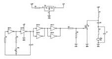
- FIG. 3is a circuit view of the ultrasonic atomization circuit of FIG. 2 .
- the ultrasonic atomization circuitincludes a driving signal generating unit 1 , a buffering unit 2 and a power unit 3 .
- the driving signal generating unit 1generates an ultrasonic driving signal which is a square-wave signal with an adjustable frequency.
- the power unit 3amplifies the driving signal and transmits it to a piezoelectric ceramic lamination.
- the buffering unit 2is connected to the driving signal generating unit 1 and the power unit 3 to reduce the effect from the load connecting to the power unit 3 to the driving signal generating unit 1 .
- the buffering unit 3can not only reduce the effect by the disperse circuits and reactance to the driving signal generating unit, meanwhile but also make the reactance of the driving signal generating unit 1 and the power unit 3 to match each other. Hence, the driving signal transmitted to the power unit 3 has a little wave shape distortion to be favorable to the power unit 3 .
- the driving signal generating unit 1includes a square-wave generating circuit, and the square-wave generating circuit includes a first not gate unit (NOT) and a second not gate unit.
- the output of the first not gate unitconnects to its input sequentially through an adjustable resistance (VR 1 ) and the first resistance (R 1 ), similarly the input of the second not gate unit connects to the output of the first not gate unit.
- the square-wave signalis transmitted from the output of the second not gate unit to the conjunction of the adjustable resistance (VR 1 ) and the first resistance (R 1 ) through a capacitor (C 3 ).
- the buffering unit 2includes two-stage series-connected phase inverters including gate circuits.
- the phase inverterincludes two parallel-connected not gate units.
- a NOT 3 and a NOT 4are parallel connection to form the first stage phase inverter, that is, the inputs of the NOT 3 and NOT 4 connect to each other, and the outputs of the NOT 3 and NOT 4 connect to each other.
- a NOT 5 and a NOT 6are parallel connection to form the second stage phase inverter, that is, the inputs of the NOT 5 and NOT 6 connect to each other, and the outputs of the NOT 5 and NOT 6 connect to each other.
- the input of the phase inverterconnects to the output of the driving signal generating unit 1 , and the output of the first stage phase inverter connects to the input of the second stage phase inverter, and the output of the second stage phase inverter connects to the input of the power unit 3 .
- the power unit 3includes a selective amplifier which can selectively amplify the square-wave signal into a sine wave signal with the same frequency and transmit the sine wave signal to the piezoelectric ceramic lamination.
- the power unit 3includes a MOSFET METAL OXIDE SEMICONDUCTOR FIELD EFFECT TRANSISTOR Q 1 , a first inductance L 3 , a second inductance L 4 , a first capacitance C 6 and a second capacitance C 7 .
- the grid electrode of the MOSFET Q 1connects to the output of the buffering unit 2 , and the source electrode to ground, the drain electrode to the power source by the first inductance L 3 .
- the drain electrode of the MOSFET Q 1connects to ground through the first capacitance C 6 , the second inductance L 4 and the piezoelectric ceramic lamination.
- the second capacitance C 7connects to the conjunction of the first capacitance C 6 and the second inductance L 4 .
- the power unitincludes a MOSFET, a first inductance, a second inductance, a first capacitance and a second capacitance.
- the grid electrode of the MOSFETconnects to the output of the buffering unit, and its source electrode to ground, and its drain electrode connects to the power unit by the first inductance.
- the MOSFETconnects to ground through the first capacitance, the second inductance and the piezoelectric ceramic lamination, and the second capacitance connects to the conjunction of the first capacitance and the second inductance.
- the first resistance R 1is to protect the input of the not gate unit.
- Vth1 ⁇ 2 VCC (most gate circuits are available for this requirement)
- Different high frequency square-wave signalscan be generated only to adjust the VR 1 .
- the frequency of the square-wave signalis equal to the central frequency of the piezoelectric ceramic lamination TD 1 .
- the high frequency square-waveis transmitted to an N-Channel power MOSFET Q 1 .
- the drain electrode of the Q 1generates an equal frequency square-wave signal, and then the square-wave signal coupled by the capacitor C 6 is transmitted to a parallel resonance frequency selection network formed by the inductance L 4 , the piezoelectric ceramic lamination TD 1 , and the capacitor C 7 .
- the square-wave signalis turned into a sine signal with the same frequency.
- the signal through the piezoelectric ceramic laminationhas an equal frequency to the central frequency of the piezoelectric ceramic lamination, a resonance will appear to make the piezoelectric ceramic lamination to generate an enough high frequency signal, that is an ultrasonic, and the ultrasonic effects on water to generate atomization.
- the power of the atomization deviceis assured by the MOSFET Q 1 .
- To adjust the adjustable resistance VR 1can change the frequency of the atomization device.
- the frequencyhas a lager difference with the central frequency (inherent frequency) of the piezoelectric ceramic lamination, the power of the atomization device may descend.
- the piezoelectric ceramic laminationcan generate a resonance by only adjusting the adjustable resistance, which can keep the atomization device on the stage of maximum power.
- the +18V DCis provided by a power adapter.
- the +18V DC voltageis turned into a stable +5V DC voltage by a voltage conversion regulator chip (78L05) to supply power to the six phase inverters.
- the six phase invertersmay be used as a 14 pins integrated logic gate circuit chip.
- the ultrasonic atomization circuithas a character of reducing the effect by the disperse circuits and reactance to the driving signal generating unit, meanwhile need less units and easy to test.
- an atomization device using the above ultrasonic atomization circuitincludes a driving signal generating unit to generate an ultrasonic driving signal, a power unit to amplify and transmit the driving signal to the piezoelectric ceramic lamination, and a buffering unit connecting to the driving signal generating unit and the power unit to reduce the effect by the load of the power unit to the driving signal generating unit.
- the driving signal generating unitincludes a square-wave generating circuit formed by not gate units.
- the square-wave generating circuitincludes a first not gate unit (NOT) and a second not gate unit.
- the output of the first not gate unitconnects to its input sequentially through an adjustable resistance, and the first resistance (R 1 ), similarly the input of the second not gate unit connects to the output of the first not gate unit.
- the buffering unitincludes two-stage series-connected phase inverters including gate circuits and the phase inverter includes two parallel-connected not gate units.
- the power unitincludes a selective amplifier which can selectively amplify the square-wave signal into a sine wave signal with the same frequency and transmit the sine wave signal to the piezoelectric ceramic lamination.
Landscapes
- Special Spraying Apparatus (AREA)
- Apparatuses For Generation Of Mechanical Vibrations (AREA)
Abstract
Description
Claims (14)
Applications Claiming Priority (2)
| Application Number | Priority Date | Filing Date | Title |
|---|---|---|---|
| CN200910189841 | 2009-09-01 | ||
| CN2009101898410ACN101642741B (en) | 2009-09-01 | 2009-09-01 | Ultrasonic wave atomization circuit and device |
Publications (2)
| Publication Number | Publication Date |
|---|---|
| US20110204160A1 US20110204160A1 (en) | 2011-08-25 |
| US8222794B2true US8222794B2 (en) | 2012-07-17 |
Family
ID=41654890
Family Applications (1)
| Application Number | Title | Priority Date | Filing Date |
|---|---|---|---|
| US12/710,411Expired - Fee RelatedUS8222794B2 (en) | 2009-09-01 | 2010-02-23 | Ultrasonic atomization circuit and an atomization device using the same |
Country Status (2)
| Country | Link |
|---|---|
| US (1) | US8222794B2 (en) |
| CN (1) | CN101642741B (en) |
Cited By (1)
| Publication number | Priority date | Publication date | Assignee | Title |
|---|---|---|---|---|
| CN110672937A (en)* | 2019-09-18 | 2020-01-10 | 北京农业智能装备技术研究中心 | Atomization efficiency evaluation method and device of electric atomizer |
Families Citing this family (11)
| Publication number | Priority date | Publication date | Assignee | Title |
|---|---|---|---|---|
| CN103604189B (en)* | 2013-05-29 | 2017-08-11 | 珠海格力电器股份有限公司 | Separate-excitation type ultrasonic atomization control circuit |
| CN104753501A (en)* | 2013-12-30 | 2015-07-01 | 上海普锐马电子有限公司 | Circuit for completing synchronous square-wave output in programmable mode |
| CN106444503A (en)* | 2016-09-30 | 2017-02-22 | 贵州德莱易环保科技有限公司 | Vehicle-mounted ultrasonic atomization drive circuit |
| CN108720081A (en)* | 2017-04-13 | 2018-11-02 | 湖南中烟工业有限责任公司 | A kind of ultrasonic electronic cigarette circuit and implementation method |
| WO2019113789A1 (en)* | 2017-12-12 | 2019-06-20 | 深圳和而泰数据资源与云技术有限公司 | Frequency locking circuit and control method therefor |
| CN108361841A (en)* | 2018-03-05 | 2018-08-03 | 四川长虹空调有限公司 | A kind of air purification method and system based on the ultrasonic water circulatory system |
| CN109258555A (en)* | 2018-11-23 | 2019-01-25 | 黄冰莹 | A kind of aquaculture perforation oxygen-increasing device based on ultrasonic atomization |
| CN111438026B (en)* | 2020-03-25 | 2022-03-11 | 广州厚达电子科技有限公司 | Driving method of ultrasonic atomizer |
| CN111636349B (en)* | 2020-06-23 | 2025-07-15 | 重庆广播电视大学重庆工商职业学院 | A ground dewatering machine |
| CN113426651A (en)* | 2021-05-21 | 2021-09-24 | 四川步歌科技有限公司 | Ultrasonic circuit and pain therapeutic apparatus comprising same |
| CN113777595B (en)* | 2021-09-14 | 2023-08-11 | 天津理工大学 | Ultrasonic wave receiving circuit |
Citations (4)
| Publication number | Priority date | Publication date | Assignee | Title |
|---|---|---|---|---|
| US4642581A (en)* | 1985-06-21 | 1987-02-10 | Sono-Tek Corporation | Ultrasonic transducer drive circuit |
| US4965532A (en)* | 1988-06-17 | 1990-10-23 | Olympus Optical Co., Ltd. | Circuit for driving ultrasonic transducer |
| US5216338A (en)* | 1989-10-05 | 1993-06-01 | Firma J. Eberspacher | Circuit arrangement for accurately and effectively driving an ultrasonic transducer |
| US7969064B2 (en)* | 2004-04-02 | 2011-06-28 | Par Technologies, Llc. | Piezoelectric devices and methods and circuits for driving same |
- 2009
- 2009-09-01CNCN2009101898410Apatent/CN101642741B/ennot_activeExpired - Fee Related
- 2010
- 2010-02-23USUS12/710,411patent/US8222794B2/ennot_activeExpired - Fee Related
Patent Citations (4)
| Publication number | Priority date | Publication date | Assignee | Title |
|---|---|---|---|---|
| US4642581A (en)* | 1985-06-21 | 1987-02-10 | Sono-Tek Corporation | Ultrasonic transducer drive circuit |
| US4965532A (en)* | 1988-06-17 | 1990-10-23 | Olympus Optical Co., Ltd. | Circuit for driving ultrasonic transducer |
| US5216338A (en)* | 1989-10-05 | 1993-06-01 | Firma J. Eberspacher | Circuit arrangement for accurately and effectively driving an ultrasonic transducer |
| US7969064B2 (en)* | 2004-04-02 | 2011-06-28 | Par Technologies, Llc. | Piezoelectric devices and methods and circuits for driving same |
Cited By (2)
| Publication number | Priority date | Publication date | Assignee | Title |
|---|---|---|---|---|
| CN110672937A (en)* | 2019-09-18 | 2020-01-10 | 北京农业智能装备技术研究中心 | Atomization efficiency evaluation method and device of electric atomizer |
| CN110672937B (en)* | 2019-09-18 | 2021-08-03 | 北京农业智能装备技术研究中心 | Atomization efficiency evaluation method and device of electric atomizer |
Also Published As
| Publication number | Publication date |
|---|---|
| CN101642741A (en) | 2010-02-10 |
| CN101642741B (en) | 2011-09-14 |
| US20110204160A1 (en) | 2011-08-25 |
Similar Documents
| Publication | Publication Date | Title |
|---|---|---|
| US8222794B2 (en) | Ultrasonic atomization circuit and an atomization device using the same | |
| US12369627B2 (en) | Ultrasonic atomizing sheet full-wave drive circuit and ultrasonic electronic cigarette | |
| CN104043577A (en) | Digitized intelligent ultrasonic power source and use method thereof | |
| US8138805B2 (en) | Complementary high voltage switched current source integrated circuit | |
| TWM603230U (en) | A resonant converter | |
| CN106093213A (en) | Portable electromagnetic ultrasonic pulse excitation apparatus | |
| CN112953483B (en) | Ultrasonic atomizer full-wave drive circuit and ultrasonic electronic cigarette | |
| CN109444524A (en) | A kind of primary side winding resonance trough sample circuit and the method for sampling | |
| CN210670015U (en) | A full-wave drive circuit for an ultrasonic atomizing tablet and an ultrasonic electronic cigarette | |
| CN204241897U (en) | A multifunctional ultrasonic transducer driving circuit | |
| CN210670027U (en) | Ultrasonic atomization piece full wave drive circuit, ultrasonic wave electron cigarette | |
| CN103326667A (en) | Sine oscillator | |
| CN201231217Y (en) | IGBT drive module and IGBT drive device | |
| CN111293867B (en) | Direct current output circuit of stack AC ripple | |
| CN103187889B (en) | A kind of portable high-pressure D.C. regulated power supply | |
| CN208225500U (en) | A kind of buzzer drive circuit and drive system | |
| JP2002119053A (en) | Switching regulator | |
| CN104883144A (en) | Oscillatory type class D amplifier for field effect switching tube phase inverter | |
| CN206117489U (en) | Numerical control and simulation hybrid -driven circuit structure | |
| CN113922698A (en) | Piezoelectric ceramic drive circuit and ultrasonic atomizer | |
| US11123766B2 (en) | Capacitive discharge push-pull converter pulser for electromagnetic acoustic transducer | |
| CN202748694U (en) | Real-time clock circuit | |
| CN219985175U (en) | A surface acoustic wave atomization circuit and aerosol generation device | |
| CN106300931A (en) | A kind of numerical control and simulation hybrid driving circuit structure | |
| CN218549760U (en) | High-frequency high-power ultrasonic driving device |
Legal Events
| Date | Code | Title | Description |
|---|---|---|---|
| AS | Assignment | Owner name:SHENZHEN H & T INTELLIGENT CONTROL CO., LTD., CHIN Free format text:ASSIGNMENT OF ASSIGNORS INTEREST;ASSIGNORS:DONG, XIAOYONG;PI, LINLIN;SUN, YIHONG;AND OTHERS;REEL/FRAME:023980/0983 Effective date:20091225 | |
| ZAAA | Notice of allowance and fees due | Free format text:ORIGINAL CODE: NOA | |
| ZAAB | Notice of allowance mailed | Free format text:ORIGINAL CODE: MN/=. | |
| STCF | Information on status: patent grant | Free format text:PATENTED CASE | |
| REMI | Maintenance fee reminder mailed | ||
| FPAY | Fee payment | Year of fee payment:4 | |
| SULP | Surcharge for late payment | ||
| MAFP | Maintenance fee payment | Free format text:PAYMENT OF MAINTENANCE FEE, 8TH YR, SMALL ENTITY (ORIGINAL EVENT CODE: M2552); ENTITY STATUS OF PATENT OWNER: SMALL ENTITY Year of fee payment:8 | |
| FEPP | Fee payment procedure | Free format text:MAINTENANCE FEE REMINDER MAILED (ORIGINAL EVENT CODE: REM.); ENTITY STATUS OF PATENT OWNER: SMALL ENTITY | |
| LAPS | Lapse for failure to pay maintenance fees | Free format text:PATENT EXPIRED FOR FAILURE TO PAY MAINTENANCE FEES (ORIGINAL EVENT CODE: EXP.); ENTITY STATUS OF PATENT OWNER: SMALL ENTITY | |
| STCH | Information on status: patent discontinuation | Free format text:PATENT EXPIRED DUE TO NONPAYMENT OF MAINTENANCE FEES UNDER 37 CFR 1.362 | |
| FP | Lapsed due to failure to pay maintenance fee | Effective date:20240717 |