US8221505B2 - Prosthesis having a sleeve valve - Google Patents
Prosthesis having a sleeve valveDownload PDFInfo
- Publication number
- US8221505B2 US8221505B2US11/709,518US70951807AUS8221505B2US 8221505 B2US8221505 B2US 8221505B2US 70951807 AUS70951807 AUS 70951807AUS 8221505 B2US8221505 B2US 8221505B2
- Authority
- US
- United States
- Prior art keywords
- sleeve
- prosthesis
- stent
- opening
- flow
- Prior art date
- Legal status (The legal status is an assumption and is not a legal conclusion. Google has not performed a legal analysis and makes no representation as to the accuracy of the status listed.)
- Active, expires
Links
- 239000012530fluidSubstances0.000claimsabstractdescription45
- 230000004044responseEffects0.000claimsabstractdescription11
- 239000000463materialSubstances0.000claimsdescription63
- 230000004048modificationEffects0.000claimsdescription9
- 238000012986modificationMethods0.000claimsdescription9
- 230000014759maintenance of locationEffects0.000claimsdescription8
- 229920000295expanded polytetrafluoroethylenePolymers0.000claimsdescription5
- 230000001154acute effectEffects0.000claims2
- 230000000151anti-reflux effectEffects0.000description34
- 210000003238esophagusAnatomy0.000description23
- 238000010992refluxMethods0.000description16
- 210000002784stomachAnatomy0.000description14
- 210000005070sphincterAnatomy0.000description13
- 206010028980NeoplasmDiseases0.000description12
- 230000005012migrationEffects0.000description10
- 238000013508migrationMethods0.000description10
- 229920002635polyurethanePolymers0.000description10
- 239000004814polyurethaneSubstances0.000description10
- 230000008673vomitingEffects0.000description9
- XLYOFNOQVPJJNP-UHFFFAOYSA-NwaterSubstancesOXLYOFNOQVPJJNP-UHFFFAOYSA-N0.000description9
- 229910052751metalInorganic materials0.000description8
- 239000002184metalSubstances0.000description8
- 241000282472Canis lupus familiarisSpecies0.000description7
- 230000002496gastric effectEffects0.000description7
- 238000000034methodMethods0.000description7
- 206010015137EructationDiseases0.000description6
- 208000027687belchingDiseases0.000description6
- 210000000941bileAnatomy0.000description6
- 210000001198duodenumAnatomy0.000description6
- 238000011156evaluationMethods0.000description6
- 239000007788liquidSubstances0.000description6
- 210000003932urinary bladderAnatomy0.000description5
- 210000004916vomitAnatomy0.000description5
- 230000004888barrier functionEffects0.000description4
- 239000000560biocompatible materialSubstances0.000description4
- 238000000338in vitroMethods0.000description4
- 210000000111lower esophageal sphincterAnatomy0.000description4
- 238000012544monitoring processMethods0.000description4
- 244000052769pathogenSpecies0.000description4
- 208000031481Pathologic ConstrictionDiseases0.000description3
- 239000004952PolyamideSubstances0.000description3
- 210000000013bile ductAnatomy0.000description3
- 210000001953common bile ductAnatomy0.000description3
- 230000006835compressionEffects0.000description3
- 238000007906compressionMethods0.000description3
- 238000001727in vivoMethods0.000description3
- 210000000056organAnatomy0.000description3
- 229920002647polyamidePolymers0.000description3
- 229920001296polysiloxanePolymers0.000description3
- 239000002002slurrySubstances0.000description3
- 150000003673urethanesChemical class0.000description3
- 210000003708urethraAnatomy0.000description3
- 241000894006BacteriaSpecies0.000description2
- 206010019909HerniaDiseases0.000description2
- 239000004677NylonSubstances0.000description2
- 206010047700VomitingDiseases0.000description2
- 239000002253acidSubstances0.000description2
- 239000000853adhesiveSubstances0.000description2
- 230000001070adhesive effectEffects0.000description2
- 210000003484anatomyAnatomy0.000description2
- 210000003445biliary tractAnatomy0.000description2
- 210000001124body fluidAnatomy0.000description2
- 210000004051gastric juiceAnatomy0.000description2
- 208000021302gastroesophageal reflux diseaseDiseases0.000description2
- 210000003736gastrointestinal contentAnatomy0.000description2
- 210000003734kidneyAnatomy0.000description2
- 229910001000nickel titaniumInorganic materials0.000description2
- 229920001778nylonPolymers0.000description2
- 210000000277pancreatic ductAnatomy0.000description2
- 229910000679solderInorganic materials0.000description2
- 210000000626ureterAnatomy0.000description2
- 210000002700urineAnatomy0.000description2
- 239000010963304 stainless steelSubstances0.000description1
- DSUFPYCILZXJFF-UHFFFAOYSA-N4-[[4-[[4-(pentoxycarbonylamino)cyclohexyl]methyl]cyclohexyl]carbamoyloxy]butyl n-[4-[[4-(butoxycarbonylamino)cyclohexyl]methyl]cyclohexyl]carbamateChemical compoundC1CC(NC(=O)OCCCCC)CCC1CC1CCC(NC(=O)OCCCCOC(=O)NC2CCC(CC3CCC(CC3)NC(=O)OCCCC)CC2)CC1DSUFPYCILZXJFF-UHFFFAOYSA-N0.000description1
- 241000191291Abies albaSpecies0.000description1
- 206010003504AspirationDiseases0.000description1
- 208000000461Esophageal NeoplasmsDiseases0.000description1
- 206010067576Malignant dysphagiaDiseases0.000description1
- 206010030155Oesophageal carcinomaDiseases0.000description1
- 239000004698PolyethyleneSubstances0.000description1
- 229910000589SAE 304 stainless steelInorganic materials0.000description1
- BQCADISMDOOEFD-UHFFFAOYSA-NSilverChemical compound[Ag]BQCADISMDOOEFD-UHFFFAOYSA-N0.000description1
- 229910000639Spring steelInorganic materials0.000description1
- HZEWFHLRYVTOIW-UHFFFAOYSA-N[Ti].[Ni]Chemical compound[Ti].[Ni]HZEWFHLRYVTOIW-UHFFFAOYSA-N0.000description1
- 229910045601alloyInorganic materials0.000description1
- 239000000956alloySubstances0.000description1
- 230000004323axial lengthEffects0.000description1
- 230000015572biosynthetic processEffects0.000description1
- 239000003518causticsSubstances0.000description1
- 230000007423decreaseEffects0.000description1
- 239000003651drinking waterSubstances0.000description1
- 235000020188drinking waterNutrition0.000description1
- 238000001839endoscopyMethods0.000description1
- 201000004101esophageal cancerDiseases0.000description1
- 210000003236esophagogastric junctionAnatomy0.000description1
- 230000001747exhibiting effectEffects0.000description1
- 238000002474experimental methodMethods0.000description1
- 210000000232gallbladderAnatomy0.000description1
- 210000001035gastrointestinal tractAnatomy0.000description1
- 239000011521glassSubstances0.000description1
- 230000036541healthEffects0.000description1
- 238000002513implantationMethods0.000description1
- 208000015181infectious diseaseDiseases0.000description1
- 238000003780insertionMethods0.000description1
- 230000037431insertionEffects0.000description1
- 230000002045lasting effectEffects0.000description1
- 235000020888liquid dietNutrition0.000description1
- 238000004519manufacturing processMethods0.000description1
- 239000003550markerSubstances0.000description1
- 230000007246mechanismEffects0.000description1
- HLXZNVUGXRDIFK-UHFFFAOYSA-Nnickel titaniumChemical compound[Ti].[Ti].[Ti].[Ti].[Ti].[Ti].[Ti].[Ti].[Ti].[Ti].[Ti].[Ni].[Ni].[Ni].[Ni].[Ni].[Ni].[Ni].[Ni].[Ni].[Ni].[Ni].[Ni].[Ni].[Ni]HLXZNVUGXRDIFK-UHFFFAOYSA-N0.000description1
- 230000001717pathogenic effectEffects0.000description1
- 229920003023plasticPolymers0.000description1
- 239000004033plasticSubstances0.000description1
- -1polyethylenePolymers0.000description1
- 229920000573polyethylenePolymers0.000description1
- 229920000642polymerPolymers0.000description1
- 230000000630rising effectEffects0.000description1
- 210000003296salivaAnatomy0.000description1
- 229910052709silverInorganic materials0.000description1
- 239000004332silverSubstances0.000description1
- 230000005477standard modelEffects0.000description1
- 208000037804stenosisDiseases0.000description1
- 230000036262stenosisEffects0.000description1
- 239000003356suture materialSubstances0.000description1
- 230000009747swallowingEffects0.000description1
- 230000007704transitionEffects0.000description1
- 230000004614tumor growthEffects0.000description1
- 230000002485urinary effectEffects0.000description1
- 210000002229urogenital systemAnatomy0.000description1
- 238000009736wettingMethods0.000description1
Images


Classifications
- A—HUMAN NECESSITIES
- A61—MEDICAL OR VETERINARY SCIENCE; HYGIENE
- A61F—FILTERS IMPLANTABLE INTO BLOOD VESSELS; PROSTHESES; DEVICES PROVIDING PATENCY TO, OR PREVENTING COLLAPSING OF, TUBULAR STRUCTURES OF THE BODY, e.g. STENTS; ORTHOPAEDIC, NURSING OR CONTRACEPTIVE DEVICES; FOMENTATION; TREATMENT OR PROTECTION OF EYES OR EARS; BANDAGES, DRESSINGS OR ABSORBENT PADS; FIRST-AID KITS
- A61F2/00—Filters implantable into blood vessels; Prostheses, i.e. artificial substitutes or replacements for parts of the body; Appliances for connecting them with the body; Devices providing patency to, or preventing collapsing of, tubular structures of the body, e.g. stents
- A61F2/02—Prostheses implantable into the body
- A61F2/04—Hollow or tubular parts of organs, e.g. bladders, tracheae, bronchi or bile ducts
- A—HUMAN NECESSITIES
- A61—MEDICAL OR VETERINARY SCIENCE; HYGIENE
- A61F—FILTERS IMPLANTABLE INTO BLOOD VESSELS; PROSTHESES; DEVICES PROVIDING PATENCY TO, OR PREVENTING COLLAPSING OF, TUBULAR STRUCTURES OF THE BODY, e.g. STENTS; ORTHOPAEDIC, NURSING OR CONTRACEPTIVE DEVICES; FOMENTATION; TREATMENT OR PROTECTION OF EYES OR EARS; BANDAGES, DRESSINGS OR ABSORBENT PADS; FIRST-AID KITS
- A61F2/00—Filters implantable into blood vessels; Prostheses, i.e. artificial substitutes or replacements for parts of the body; Appliances for connecting them with the body; Devices providing patency to, or preventing collapsing of, tubular structures of the body, e.g. stents
- A61F2/02—Prostheses implantable into the body
- A61F2/24—Heart valves ; Vascular valves, e.g. venous valves; Heart implants, e.g. passive devices for improving the function of the native valve or the heart muscle; Transmyocardial revascularisation [TMR] devices; Valves implantable in the body
- A61F2/2476—Valves implantable in the body not otherwise provided for
- A—HUMAN NECESSITIES
- A61—MEDICAL OR VETERINARY SCIENCE; HYGIENE
- A61F—FILTERS IMPLANTABLE INTO BLOOD VESSELS; PROSTHESES; DEVICES PROVIDING PATENCY TO, OR PREVENTING COLLAPSING OF, TUBULAR STRUCTURES OF THE BODY, e.g. STENTS; ORTHOPAEDIC, NURSING OR CONTRACEPTIVE DEVICES; FOMENTATION; TREATMENT OR PROTECTION OF EYES OR EARS; BANDAGES, DRESSINGS OR ABSORBENT PADS; FIRST-AID KITS
- A61F2/00—Filters implantable into blood vessels; Prostheses, i.e. artificial substitutes or replacements for parts of the body; Appliances for connecting them with the body; Devices providing patency to, or preventing collapsing of, tubular structures of the body, e.g. stents
- A61F2/02—Prostheses implantable into the body
- A61F2/04—Hollow or tubular parts of organs, e.g. bladders, tracheae, bronchi or bile ducts
- A61F2/06—Blood vessels
- A—HUMAN NECESSITIES
- A61—MEDICAL OR VETERINARY SCIENCE; HYGIENE
- A61F—FILTERS IMPLANTABLE INTO BLOOD VESSELS; PROSTHESES; DEVICES PROVIDING PATENCY TO, OR PREVENTING COLLAPSING OF, TUBULAR STRUCTURES OF THE BODY, e.g. STENTS; ORTHOPAEDIC, NURSING OR CONTRACEPTIVE DEVICES; FOMENTATION; TREATMENT OR PROTECTION OF EYES OR EARS; BANDAGES, DRESSINGS OR ABSORBENT PADS; FIRST-AID KITS
- A61F2/00—Filters implantable into blood vessels; Prostheses, i.e. artificial substitutes or replacements for parts of the body; Appliances for connecting them with the body; Devices providing patency to, or preventing collapsing of, tubular structures of the body, e.g. stents
- A61F2/02—Prostheses implantable into the body
- A61F2/24—Heart valves ; Vascular valves, e.g. venous valves; Heart implants, e.g. passive devices for improving the function of the native valve or the heart muscle; Transmyocardial revascularisation [TMR] devices; Valves implantable in the body
- A—HUMAN NECESSITIES
- A61—MEDICAL OR VETERINARY SCIENCE; HYGIENE
- A61F—FILTERS IMPLANTABLE INTO BLOOD VESSELS; PROSTHESES; DEVICES PROVIDING PATENCY TO, OR PREVENTING COLLAPSING OF, TUBULAR STRUCTURES OF THE BODY, e.g. STENTS; ORTHOPAEDIC, NURSING OR CONTRACEPTIVE DEVICES; FOMENTATION; TREATMENT OR PROTECTION OF EYES OR EARS; BANDAGES, DRESSINGS OR ABSORBENT PADS; FIRST-AID KITS
- A61F2/00—Filters implantable into blood vessels; Prostheses, i.e. artificial substitutes or replacements for parts of the body; Appliances for connecting them with the body; Devices providing patency to, or preventing collapsing of, tubular structures of the body, e.g. stents
- A61F2/02—Prostheses implantable into the body
- A61F2/04—Hollow or tubular parts of organs, e.g. bladders, tracheae, bronchi or bile ducts
- A61F2002/044—Oesophagi or esophagi or gullets
Definitions
- This inventionrelates generally to medical devices, and in particular, to an indwelling valved prosthesis.
- Anti-reflux esophageal prosthesis or stentsare typically placed in the lower esophagus and through the lower esophageal sphincter to maintain the patency thereof due to the presence of a cancerous tumor commonly found in the vicinity thereof.
- the cancerous tumor growthtypically impinges the flow of food and fluids through the esophagus.
- Lower esophageal cancer in the United Statespresently occurs at the rate of approximately 12,000 patients per year. The incidence in the United States is approximately 5.1 per 100,000 people, and is rising, particularly in white male patients. Esophageal prosthesis or stents are typically utilized in these cancerous patients.
- a problem with esophageal prosthesis or stentsis that fluid from the stomach flows into the mouth of the patient when in a prone position.
- a number of esophageal prosthesis or stentsutilize a one-way valve such as a duck-bill or reed-type valve in which food or fluid from the esophagus flows into the stomach in only an antegrade or forward direction.
- these one-way anti-reflux prosthesis or stentspresent certain problems. For example, when the patient wants to belch or vomit, he/she is prevented from doing so because the one-way valve prevents backward flow in the retrograde direction. Such a condition is not only painful to the patient, but can also lead to more complicated medical conditions.
- a prosthesismay be placed to maintain an open lumen for passage of bodily fluids.
- Such prosthesismay create the risk of undesirable retrograde flow and/or migration of pathogenic organisms, which could lead to infection or other problems, such as obstruction of the stent.
- a drainage stent or catheteris placed across a sphincter or natural stricture at the opening to a bodily passage, the sphincter or stricture cannot fulfill its normal function of restricting retrograde flow or migration. What is needed is a prosthesis and one-way valve that can effectively regulate antegrade and retrograde flow in response to the normal flow rates and pressures that exist across the site in which the prosthesis is placed.
- the prosthesiscomprises an anti-reflux esophageal prosthesis in which a sleeve extending from a tubular frame thereof inverts through the passage of the tubular frame and allows stomach gas or vomit to flow in a retrograde direction when the pressure in the stomach exceeds a given level (a third pressure higher than the second pressure).
- a sleeveIn the antegrade or downward position, the sleeve collapses and prevents the reflux of stomach gas and fluid from flowing through the esophagus and into the mouth of the patient.
- the collapsible sleevefunctions as a one-way valve and allows the patient to ingest or pass liquid and food therethrough and into the stomach.
- tubular frame of this advantageous anti-reflux esophageal prosthesismaintains the patency of the lower esophagus and sphincter, particularly when, for example, a cancerous tumor would otherwise impede fluid flow through the esophagus.
- the tubular frame of the anti-reflux esophageal prosthesisincludes a plurality of self-expanding zig-zag stents.
- the compressed stents, along with the sleeve,are positioned in a delivery catheter that is orally passed through the esophagus and lower sphincter.
- the prosthesisis then deployed from the delivery catheter with, for example, a dilator or pusher catheter that is inserted in and/or through the lumen of the delivery catheter.
- the self-expanding stentsreadily expand to engage and maintain the esophagus and lower sphincter in a patent condition.
- the self-expanding stents of the tubular frameare also advantageously flared at each end of the tubular frame to prevent antegrade and retrograde migration of the expanded prosthesis.
- a filamentis circumferentially positioned through closed eyelets at the bends of adjacent zig-zag stents.
- the filamentsare also utilized advantageously to control the radial expansion and the flared configuration of the stents positioned at the ends of the tubular frame.
- the pressure needed to collapse or invert the one-way valvular sleeveis a function of the sleeve material, its wall thickness, and length extending from the distal end of the tubular frame.
- the sleevecan extend from the end of the frame for a length in a range of from 0.0 to 20 cm, and preferably in a range of 5 to 15 cm; and more preferably in a length of approximately 10 cm for a human patient or 8 cm for a veterinary patient, as experimentally derived therefor.
- the sleeve materialalso advantageously includes a material of polyurethane, silicone, polyamides, other urethanes or any biocompatible material that is flexible and acid resistant.
- the sleeve materialat the portion covering the frame itself, can have an advantageous thickness of 0.005′′ through 0.01′′.
- the sleeve extending from an end of the framecomprises a material having a thickness in a range of 0.0015′′ to and including 0.01′′.
- the length of the sleeveis made long enough so that it can be readily shortened to accommodate individual anatomical situations.
- the sleeveis configured to reduce the tendency of it to invert through the tubular frame during episodes of increased gastric pressure (third pressure), such as belching, where it is not necessarily important physiologically that inversion take place.
- third pressuregastric pressure
- a portion of the sleevemay be modified to make it more difficult to invert.
- One such modificationis to widen the sleeve toward the first end thereof (i.e., the end of the sleeve distanced away from the tubular frame), such that the sleeve is tapered or bell-shaped. The wider first end would be less likely to invert back through the narrower tubular frame.
- a second modificationis to add a stiffened region, such as a ring, about the first end so as to inhibit the sleeve from inverting back through tubular frame in response to a third gastric pressure, such as belching, that is higher than the second pressure acting on the valve to keep it closed in the absence of incoming flow (first pressure).
- a third gastric pressuresuch as belching
- the intentis limit or prevent inversion when the third pressure is not sufficiently high to warrant an inversion that is necessary for patient health or comfort, especially given that the patient must re-invert the sleeve by swallowing liquid following each such episode.
- the ring or stiffened region of the sleevecan comprise a rolled first end of the sleeve, a thickened edge of sleeve material, or one or more rings or similar elements affixed to the sleeve material.
- the sleevecan be configured such that it closes above or below the stiffened region or ring.
- the collapsible sleeveis attached to a proximal end of the tubular frame, such that the sleeve extends distally through the tubular frame.
- the collapsible sleeveis attached to a tubular drainage stent, such as a biliary stent, to advantageously prevent reflux of intestinal contents and the associated bacteria into the passage of the stent.
- a tubular drainage stentsuch as a biliary stent
- These bacteriaare known to promote the formation of a biofilm that can lead to occlusion of the stent.
- the sleeveWith the stent placed in the biliary tree for maintaining patency of the bile or pancreatic duct and the Papilla of Vater, the sleeve extends down into the duodenum to provide a one-way valve for the flow of bile.
- Tubular drainage stents for placement in the ureters or urethracan include either a sleeve extending from one end to permit urine flow but prevent retrograde flow or pathogen migration toward the kidneys or bladder, or the sleeve may be located completely within the lumen of the drainage stent with one end of the sleeve being bonded or otherwise attached to the inner walls of the lumen.
- the stentin yet another aspect of the present invention, includes first opening and a second opening configured for allowing fluid flow from the passage to the lumen in the first direction.
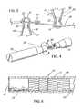
- FIG. 1depicts a pictorial view of an illustrative embodiment of a pressure sensitive anti-reflux esophageal prosthesis of the present invention
- FIG. 2depicts an enlarged cross-sectional view of a sleeve about a cylindrical wire of a flared stent of the esophageal prosthesis taken along line 2 - 2 of FIG. 1 ;
- FIG. 3depicts an enlarged partially sectioned view of the adjacent ends of interconnected stents of the prosthesis of FIG. 1 ;
- FIG. 4depicts a two piece mandril that is used to apply the sleeve material to the prosthesis of FIG. 1 ;
- FIG. 5depicts the esophageal prosthesis of FIG. 1 deployed in the lower esophagus of a patient, and in particular, through the lower esophageal sphincter and a cancerous tumor;
- FIG. 6depicts the anti-reflux esophageal prosthesis of FIG. 1 in a collapsed state in a delivery catheter;
- FIG. 7depicts the delivery catheter of FIG. 6 positioned in the lower esophagus, sphincter, and tumor of a patient;
- FIG. 8depicts an in-vitro barrier reflux curve for an anti-reflux esophageal prosthesis of the present invention
- FIGS. 9 and 10depict the percent of fraction time of standard and anti-reflux esophageal prosthesis utilized in an evaluation of the present invention
- FIG. 11depicts a pictorial view of an embodiment of a tubular drainage prosthesis of the present invention.
- FIG. 12depicts a cross-sectional view of a second embodiment of a tubular drainage prosthesis
- FIG. 13depicts the prosthesis of FIG. 11 positioned in the common bile duct of a patient
- FIG. 14depicts a side view of the prosthesis of FIG. 11 mounted on a delivery system
- FIG. 15depicts a side view of one end of a valved prosthesis that includes a pigtail configuration
- FIG. 16depicts a laterally sectioned view of a valved prosthesis in which the sleeve is affixed with the lumen;
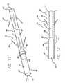
- FIG. 17depicts a pictorial view of second embodiment of a pressure sensitive anti-reflux esophageal prosthesis of the present invention.
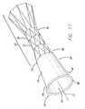
- FIG. 18depicts a pictorial view of a third embodiment of a pressure sensitive anti-reflux esophageal prosthesis of the present invention.
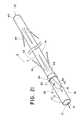
- FIG. 19depicts a pictorial view of a fourth embodiment of a pressure sensitive anti-reflux esophageal prosthesis of the present invention.
- FIG. 20depicts a pictorial view of an embodiment of the tubular drainage prosthesis shown in FIG. 11 and having a side opening;
- FIG. 21depicts a pictorial view of an embodiment of the tubular drainage prosthesis of FIG. 11 and having an angled portion at an end of the prosthesis.
- FIGS. 1-14depict exemplary prostheses of the present invention comprising a tubular member 11 with a passage 12 therethrough, and a thin, flexible sleeve 13 extending from the tubular member 11 .
- the sleeve 13which also has a passage 15 therethrough, is configured to allow the flow of liquid or other materials moving under a first pressure until the flow and pressure are lessened to where they are exceeded by a second, back pressure of the drainage environment, at which time the sleeve 13 collapses to prevent the ingress of fluids of materials into the tubular member.
- FIG. 1depicts a pictorial view of an illustrative, preferred embodiment of pressure sensitive anti-reflux esophageal prosthesis 10 of the present invention.
- the prosthesisincludes a tubular frame 11 of a plurality 19 of self-expanding, zig-zag wire stents 20 , 21 , and 23 covered by a polyurethane sleeve 13 that is disposed around and extends along the entire length 27 of the tubular frame.
- the sleevealso extends from distal end 14 of the self-expanding tubular frame and has a lumen 15 extending longitudinally therethrough. Lumen 15 of the sleeve also communicates with passage 12 of the tubular frame.
- lumen 15 in the lower portion 28 of the sleevecollapses upon itself due to wetting by gastric juices, fluid or saliva flowing therethrough from the esophagus in a first direction 17 .
- sleeve 13is in a collapsed position and acts as a one-way valve into the stomach, thereby preventing the reflux of gastric fluid from flowing in a retrograde manner, referred to herein as the second direction 18 , through the prosthesis and esophagus and into the mouth of the patient.
- fluidmay readily flow in the opposite (first) direction 17 from the esophagus and through the one-way valve sleeve into the patient's stomach.
- Tubular frame 11includes plurality 19 of self-expanding stents 20 , 21 , and 23 that are interconnected circumferentially by filament 24 about adjacent ends 25 and 26 of the stents.
- the tubular frameincludes four self-expanding, zig-zag wire metal stents of the Gianturco type as described in U.S. Pat. No. 4,580,568, which is incorporated by reference herein.
- the illustrative stent configurationis merely exemplary, and it is contemplated that other stents and stent configurations may be substituted for the illustrative stent frame.
- the tubular frameincludes first and second flared stents 20 and 21 positioned at distal and proximal ends 14 and 22 , with first and second cylindrical stents 23 positioned therebetween.
- first and second flared stents 20 and 21have a minimum diameter of 18 mm and a flared diameter of approximately 25 mm. These diameters are nominal diameters for the stents and can be customized to meet the particular demands of any human or veterinary patient.
- the diameter of the flared endis maintained by end filament 29 .
- the minimum diameter of the flared stents along with the nominal diameter of the cylindrical stentsis maintained by interconnecting filaments 24 .
- the interconnecting and end filaments 24 and 29are, for example, 3/0 diameter mononylon suture material.
- the first and second flared stents 20 and 21are positioned below and above the lower esophageal sphincter and prevent the migration of the prosthesis in either the antegrade or retrograde direction with respect to the esophagus.
- the flared proximal stent, along with the cylindrical stents 23expand against any tumor that is in the region of the lower esophagus and maintains the patency of the lower esophageal lumen.
- Flared stents 20 and 21are, for example, are formed from commercially available Series 304 stainless steel cylindrical wire having a diameter of approximately 0.015′′.
- the wireis formed into a zig-zag pattern of which the ends are joined together using, for example, a metal sleeve and soldered together using silver/tin solder.
- the flared or maximum diameter of the flared stentsis approximately 25 mm with the minimum diameter at approximately 18 mm.
- Interconnecting cylindrical stents 23are also formed from the same cylindrical wire and have a nominal diameter of approximately 18 mm, matching that of the minimum diameter of the flared stents.
- the length of the individual stentsis approximately 2 cm.
- the overall length of the tubular framecan range from 8 to 14 cm in 2 cm increments. These 2 cm increments are typically provided by increasing the number of interconnecting cylindrical stents 23 .
- Sleeve 13preferably comprises a polyurethane material or other liquid impermeable material that will not degrade in the presence of fluids or other gastric materials that it may come into contact with.
- the sleeveis disposed around, and extends at least partially around, tubular frame 11 .
- the sleeveextends the entire length of the frame and extends longitudinally from the distal end 14 of the tubular frame.
- the length of the sleeve material extending from the distal end of the tubular framecan range from 0 through 20 cm, preferably 5 to 15 cm, and more preferably from 7-10 cm.
- the length of the sleeve materialcan also be individually customized by the physician depending on the anatomy of the patient.
- the wall thickness of the sleeve material disposed around the tubular frameis approximately 0.006-0.01′′ thick.
- the thickness of the sleeve material along lower portion 28 of the sleevemay be thinner, e.g., approximately 0.002′′ thick; however, a thicker sleeve, such as 0.0095′′, may advantageously reduce the tendency of the sleeve to invert at back pressures (e.g., belching) below that which are deemed necessary for patient relief.
- the sleeve materialpreferably includes a medical grade polyurethane material, although silicone, nylon, polyamides such as other urethanes, or other biocompatible materials that are flexible and acid resistant are also suitable materials.
- the sleeve materialis a medical grade polyurethane material grade EG-80A material commercially known as TECOFLEX® polyurethane material from Thermedics, Inc., Woburn, Mass.
- FIG. 2depicts an enlarged sectioned end view, taken along line 2 - 2 of FIG. 1 , of sleeve 13 about cylindrical wire 30 of flared stent 20 .
- the thickness of the sleeve materialis approximately 0.006′′, whereas the thickness of the sleeve material along lower or distal portion 28 thereof is preferably and approximately 0.002′′.
- the thickness of sleeve material above distal portion 28ranges from 0.005′′ through 0.01′′. Experimental data has indicated that the sleeve material along distal portion 28 will still collapse at a 0.01′′ wall thickness so as to effectively form a one-way valve.
- closure of the one-way valve sleeve materialis most reliable at or below 0.004′′, since closure of sleeves with a thickness above this dimension may not occur each time on a guaranteed basis.
- a thicker sleeve(0.004-0.01′′) may be desired.
- a thickness of the sleeve wall material below 0.0015′′may present a problem of tearing, particularly when inserting the prosthesis into a delivery catheter.
- FIG. 3depicts an enlarged partially sectioned view of adjacent ends 25 and 26 of interconnected stents 20 and 23 of FIG. 1 .
- Bends 31 of cylindrical wire 30are formed into a keyhole configuration with silver solder 32 interconnecting the wire arms, thereby forming an aperture or eyelet 33 .
- Interconnecting filament 24is positioned through each eyelet and wound around at least once to aid in fixing the diameter of the expandable stents.
- One interconnecting or end filamentis used at the end of each stent and tied at the loose ends with suture knot 34 .
- FIG. 4depicts a two piece mandril 35 that is used to apply sleeve material 13 to the prosthesis of FIG. 1 .
- the mandrilincludes sleeve portion 36 and upper frame portion 37 , which are interconnectable with, for example, threaded rod 38 and internally threaded channel 39 .
- the tubular frame including the plurality of self-expanding wire stentsare positioned end-to-end and interconnected using interconnecting filament 24 .
- the end filamentis also positioned through the eyelets of the flared stents to control the maximum diameter thereof.
- the mandrilhas a minimum inner diameter matching that of the inside diameter of the inner stents and a flared diameter matching that of the flared stents.
- the mandrilassumes the inner diameter of the one-way valve sleeve material.
- the assembled tubular frameis positioned between the upper frame portion of the sleeve portion of the mandril.
- the two portions of the mandrilare then interconnected, thereby filling up the passage of the tubular frame.
- the tubular frameis then dipped into a slurry material of polyurethane to form an initial 0.004′′ thickness over the entire length of the tubular frame.
- the mandril and covered tubular frameare then dipped in the slurry material at least one additional time to form the desired thickness of the sleeve material over mandril sleeve portion 36 . After the slurry material cures, the two portions of the mandril are disconnected to form the anti-reflux esophageal prosthesis.
- FIG. 5depicts esophageal prosthesis 10 deployed in lower esophagus 40 , and, in particular, through lower esophageal sphincter 41 and cancerous tumor 42 .
- Distal flared stent 20typically extends into the stomach along with sleeve 13 .
- Flared stent 21is positioned proximal to the sphincter and tumor, whereas the interconnected cylindrical stents are typically positioned through the sphincter and tumor.
- the flared stents 20 and 21prevent the migration of the prosthesis within the esophagus.
- the lower or distal portion 28 of sleeve 13extends into stomach 43 .
- the lumen of the lower sleeve portionreadily collapses when in contact with any external fluid applied thereto.
- any liquid or foodis readily passed in an antegrade direction through the esophageal stent and into the stomach.
- one-way valve sleeve 13opens to provide flow in the antegrade direction.
- any fluids or food material 44are prevented from flowing into the retrograde direction due to the collapsed lumen of sleeve 13 .
- sleeve 13will invert and extend in an antegrade direction through the lumen of the tubular frame as shown by phantom lines 45 . In this position, gastric fluid and matter flows in the retrograde direction to relieve the patient.
- the length of distal portion 28 of the sleeve and the thickness thereofcontrol the pressure at which the distal portion of the sleeve inverts through the tubular frame.
- Self-expanding esophageal prosthesisare increasingly being used for palliation of malignant dysphagia.
- these devicescan predispose a patient to significant gastroesophageal reflux, including risk of aspiration, when deployed across the gastroesophageal junction.
- a studywas performed to evaluate the anti-reflux efficacy of a esophageal prosthesis of the present invention to prevent reflux.
- a model EZS 21-8 from Wilson-Cook Inc., Salem, N.C. (16 mm diameter)was modified by extending its polyurethane covering 7 cm beyond its distal metal cage so as to form a “windsock” or collapsible sleeve.
- the pressure required to invert the windsock or collapsible sleeve into the tubular framewas determined by attaching the proximal end of the prosthesis to a hollow graduated tube and vertically inserting the stent under water until the windsock inverted.
- the pressure required to revert the windsock or collapsible lumen to its original one-way positionwas subsequently determined by pouring water into the lumen of the prosthesis.
- In-vivo evaluationwas done in two esophagostomized dogs (male—18 kg, female—16 kg). Prosthesis insertion, positioning, and removal were accomplished by standard endoscopic and fluoroscopic techniques.
- FIG. 6depicts the anti-reflux esophageal prosthesis 10 of FIG. 1 in a collapsed state in delivery catheter 46 .
- Sleeve material 13is positioned at the distal end of the delivery catheter.
- the prosthesisis drawn into the delivery catheter with a drawstring attached at the proximal end of the prosthesis.
- the drawstring and prosthesisare inserted through lumen 47 of the catheter by collapsing the tubular frame and then pulling the prosthesis into the distal end of the delivery catheter with the drawstring.
- a pusher catheter 48is positioned proximally in lumen 47 to engage the proximal end of the wire tubular frame 11 .
- FIG. 7depicts delivery catheter 46 of FIG. 6 positioned in lower esophagus 40 and sphincter 41 of a patient, and adjacent to tumor 42 .
- the distal end of the delivery catheterextends into stomach 43 .
- the pusherhas been placed in the lumen of the delivery catheter and engages the proximal end of prosthesis 10 .
- sleeve 13 and flared distal stent 20have been deployed from the distal end of the catheter.
- the delivery catheteris partially withdrawn so as to engage the flared stent with the neck of the stomach about sphincter 41 .
- the delivery catheteris pulled back while maintaining the position of the pusher catheter therein so as to release the central cylindrical stents and proximal flared stent against the sphincter, tumor, and lower esophagus.
- FIG. 8depicts in-vitro reflux barrier curve 48 that illustrates the water column height in centimeters necessary to invert a given sleeve length extending from the distal end of the prosthesis.
- Rectangular median value boxes 49indicate the median value of the water column height at the indicated sleeve lengths.
- the vertical bar 50 positioned on curve 48 with rectangular median value boxes 49represent a standard deviation above and below the indicated median value.
- the number of reflux episodeswas monitored at the distal and proximal ends of the prosthesis. With a standard prosthesis without a one way valve, 197 episodes of reflux were encountered in 250 attempts. At the proximal end of the standard tubular esphageal prosthesis, a total of 33 reflux episodes were noted with 50 attempts.
- FIG. 9depicts the fraction time percentages of which the esophagus was exposed to gastric juice with a pH less than 4.
- the percentage of fraction timeis indicated by boxes 51 for the four dogs at the distal end of the standard prosthesis. These percentage fraction times range from 20-80% with a median value of 49%.
- the percentage of fraction timeranges from 0.0 to approximately 1.5% with a median value of 1% as indicated by boxes 52 . The p-values for these fraction times is 0.026.
- FIG. 10depicts the fraction time percentages at the proximal ends of the standard and anti-reflux prosthesis.
- Boxes 53represent the percent fraction time for the standard prosthesis which ranges from approximately 4-14% with a median of 6.6%.
- Rectangular boxes 54represent the percent fraction time for the anti-reflux prosthesis, which range from approximately 0.0 to 1.0%. These have a p-value of approximately 0.055.
- the modified self-expanding metal esophageal stent of the present inventionis highly effective in preventing gastro-esophageal reflux.
- the ability of the modification to invert at higher pressure gradientsallows for belching and vomiting. Once inverted, reversion to the anti-reflux position of the prosthesis requires minimal pressure that can be achieved by a water swallow.
- FIG. 17A related esophageal embodiment of the present invention is depicted in FIG. 17 , in which a portion of the collapsible sleeve 13 is adapted to be resistant to inversion through the tubular frame in response to a third pressure, such as belching.
- a third pressuresuch as belching.
- at least a portion of the sleeveis wider toward the first end 67 than it is at the second end 68 (the end of the collapsible portion at the junction with the end 14 of the tubular frame 11 comprising the plurality of expandable stents 19 ), such that the sleeve 13 is flared, tapered, conical or bell-shaped.
- the surface of the portion of the sleeve 13 extending between first end 67 and the second end 68could be straight, convex, or concave, or any combination of these shapes, so long as the first end 67 is wider than the second end 68 .
- the width of the second end 68is approximately 25 mm. From this point the sleeve diameter widens until it reaches approximately 31 mm at the first end 67 .
- the wider, first end 67helps prevent the collapsible sleeve 13 from inverting through the tubular frame. As explained above, inversion of the collapsible sleeve requires that the patient to subsequently take a drink of water to re-invert the sleeve back to the anti-reflux position.
- a second modification of the embodiment of FIG. 17 intended to prevent the collapsible sleeve 13 from inverting into the frame 11is a thickened or stiffening region 80 , such as the illustrative ring at the first end 67 of the sleeve 13 . More than one ring may be present, or the thickened region(s) 80 can comprise various non-annular configurations.
- the stiffening ring 80which can comprise a rolled first end 67 of the sleeve, a thickened edge formed with additional sleeve material, or a ring of material that has been affixed to the sleeve, adds rigidity to the sleeve and decreases the likelihood that it will invert in situations during which it is not desirable or necessary for inversion to take place. The addition of either of these modifications may also permit the sleeve material to be thinned to produce a better seal against normal back pressure 18 of fluids.
- a sleeve 13 having a thickness of 0.004 or 0.005′′collapses more readily, it can sometimes invert back through the stent at back pressures where inversion would not truly be necessary to relieve problematic gastric pressure or to vomit, thereby requiring that the patient drink a glass of liquid to re-invert the sleeve.
- Inversion through the tubular frame 11should be a relatively rare event, and in some patients, such as those having a Nissan Fundiplication, may not be necessary due to a greatly reduced ability to belch or vomit.
- the sleevemay be thickened, e.g., to 0.0095′′ to make inversion through the frame more difficult. Although a thicker sleeve is more difficult to re-invert, it may not make an optimal valve.
- the ring 80 and/or distal enlargement of the sleeve 12represent other ways to address the inversion problem.
- the illustrative modificationsmay also allow the sleeve to be made shorter (e.g., less than 8 cm) and still retain the desired valve characteristics.
- anti-inversion features depicted in FIG. 17may be applied to other types of stents and to prostheses placed elsewhere in the body to serve as a valve.
- the above-described anti-inversion featuresmay be used on tubular drainage stents of the type described below.
- FIGS. 18-19illustrate an embodiment of a pressure sensitive anti-reflux esophageal prosthesis 10 in which the collapsible sleeve 13 extends distally from the proximal end 22 of the tubular frame.
- the prosthesisincludes a tubular frame 11 of a plurality 19 of self-expanding, zig-zag wire stents 20 , 21 , and 23 .
- the tubular frame 11includes a proximal end 22 and a distal end 14 .
- a sleeve 13is attached to the proximal end 22 , rather than the distal end 14 .
- the sleeve 13extends distally through passage 12 of the tubular frame.
- the sleeveextends distally through a portion of the length of the passage 12 .
- the sleeve 13can be everted (shown as everted sleeve 113 ).
- the sleevecan also be provided in shorter or longer lengths.
- the sleevecan be provided in lengths greater than, less than, or equal to the axial length of the tubular frame.
- the embodiment illustrated in FIG. 18includes a sleeve that is shorter than the tubular frame.
- a sleeve having a shorter length than the tubular framemay be particularly well-suited for use with patients suffering from hiatial hernia.
- patients with hiatial herniathere is often a compression of the esophagus at the esophageal junction adjacent the diaphragm.
- This compressionin some circumstances can be severe enough to compress or pinch the sleeve valve, and possibly prevent it from everting.
- the sleeveis protected from such compression or pinching because the entire length of the sleeve is disposed within the tubular member, which traverses the problematic esophageal junction.
- the embodiment illustrated in FIG. 19includes a sleeve that is longer than the tubular frame 11 .
- the sleeve 13can be everted (shown as everted sleeve 113 ) to extend proximally from the proximal end 22 of the tubular frame. This allows a patient to vomit or belch when necessary, as described above. As described above with respect to previous embodiments, the patient can cause the sleeve to return to its normal first configuration by, for example, drinking water.
- the prostheses 10 illustrated in FIGS. 18-19can also be provided with the anti-inversion features depicted in FIG. 17 .
- the sleeve 13can be provided with rings, a bell-shaped portion, portions of varying thickness or stiffness, and the like, as described in detail above.
- the prosthesis 10 and tubular member 11comprise a tubular drainage stent 60 having a first end 62 for drainage into a duct, vessel, organ, etc., and a second end 63 that receives the fluid or other material that is moving under a first, antegrade pressure and direction 17 .
- a tubular drainage stentor tubular drainage catheter
- a tubular drainage stentis typically an elongate, closed tubular conduit (typically plastic or metal) that is placed within a bodily passage, such as the bile duct, pancreatic duct, urethra, etc. to facilitate the flow of fluids therethrough.
- the tubular drainage stentmay also include a retention means 64 , 65 at one or more ends 62 , 63 , such as flaps, barbs, pigtail loops, etc.
- the tubular drainage stent 60is attached to the collapsible sleeve 13 , which acts as a one-way valve to prevent retrograde flow 18 therethrough.
- the first end 67 of the sleeveis maintained open when the fluid or material passing through the sleeve is exhibiting a pressure associated with normal antegrade flow 17 .
- the first end 67collapses shut when the antegrade flow 17 has ceased or lessened such that the second fluid pressure 18 occurring in the environment into which the fluid is drained becomes higher than the first pressure of the antegrade flow 17 .
- bileis able to flow into the duodenum 71 .
- the sleeve 13closes in the absence of measurable flow 17 , thus preventing the contents of the intestinal tract, which now have a second, higher pressure 18 , from entering the passageway of the stent.
- the sleeve 13is made of a biocompatible material that will not degrade when placed in the particular environment of the human body into which it is to be placed. Possible materials include expanded polytetrafluoroethylene (ePTFE), polyurethane, silicone, nylon, polyamides such as other urethanes, or other biocompatible materials. It is important that the sleeve material be selected appropriately.
- the sleeveis typically made of a 2-3 cm section of ePTFE, which is much more resistant to caustic bile than would be a sleeve of polyurethane.
- the ePTFE tubeis extruded into a thin wall tube having sufficient flexibility to collapse and seal against the ingress of fluid, while having sufficient integrity to resist tearing.
- the normal range of sleeve thickness for the illustrative embodimentis 0.001 to 0.01 in., with a more preferred thickness of 0.002 to 0.005 in (e.g., 0.0025).
- the second end 68 of the sleeveis attached about the first end 62 of a biliary stent 60 , such as a ST-2 SOEHENDRA TANNENBAUM® stent, a COTTON-LEUNG® stent or a COTTON-HUIBREGTSE® stent (Wilson-Cook Medical Inc., Winston-Salem, N.C.), by an attachment means 66 , such as an illustrative crimped metal band. This band 66 can also be made radiopaque so as to serve as a fluoroscopic marker. Other methods of attachment could include, suture binding, selected medical grade adhesives, or thermal bonding, if appropriate for both the sleeve and stent polymers.
- a biliary stent 60such as a ST-2 SOEHENDRA TANNENBAUM® stent, a COTTON-LEUNG® stent or a COTTON-HUIBREGTSE® stent (W
- FIG. 12An alternative method of forming the sleeve for a tubular drainage stent 60 is depicted in FIG. 12 .
- the wall of the tubular memberwhich is made of polyethylene in this embodiment, is thinned out distally from the first end 62 of the tubular drainage stent 60 , such that the sleeve 13 is integral with the tubular member 11 .
- a transition zone 77exists between the first end tubular drainage stent 60 and the second end 68 of the sleeve 13 , beyond which the sleeve 13 becomes sufficiently thin to collapse into a closed position in the absence of antegrade flow 17 , such as bile.
- FIG. 13depicts how the illustrative embodiment is used within the common bile duct 69 to permit the drainage of bile across the Papilla of Vater 70 and into the duodenum 71 .
- the biliary stent 60is positioned in the normal manner inside the common bile duct 69 with the first end 62 of the stent extending outside of the duct and Papilla of Vater 70 .
- the first retention means 64abuts the opening of the sphincter to prevent ingress of the stent 60 into the duct while the second retention means 65 , located about the second end 63 , is positioned well inside the duct to prevent the stent 60 from migrating outward.
- the sleeve 13lies completely within the duodenum, where it acts as a one-way valve to prevent intestinal contents from entering the biliary stent 60 .
- the sleeve 13is not designed to invert back through the tubular member 13 in the presence of a third, significantly higher pressure, a situation which is normally not found inside the duodenum, or even clinically necessary as with the esophageal embodiment where belching or vomiting make such a capability desirous. Accordingly, it may be desirable to incorporate one or more of the anti-inversion features depicted in FIG. 17 .
- Placement of the embodiments of FIGS. 11-12can be accomplished by a system such as that depicted in FIG. 14 .
- the biliary stent 60is mounted on a guiding catheter 73 which is fed over a standard biliary exchange wire guide 74 into the bile duct.
- a pusher element 72is used with the distal end 75 of the pusher contacting the first end 62 of stent 60 and urging it forward until deployment occurs.
- the sleeve 13is normally folded in accordion fashion prior to deployment, whereby it resumes its elongated configuration once the prosthesis 10 has been properly positioned.
- FIG. 15depicts a prosthesis 10 comprising a tubular drainage stent 60 that is configured for placement in the urinary system, such as within the ureter between the kidney and the bladder.
- the sleeve 13is attached to the first end 62 of the tubular drainage stent 60 , which includes a first retention means 64 that comprises a pigtail configuration 79 .
- the pigtail 79would be placed within the bladder to prevent migration of the stent.
- a pigtail configuration 79can be used to anchor the second end of the stent (not shown), typically within the ureteropelvic junction.
- the pigtail configurationis exemplary of a large variety of well know pigtail ureteral and urethral stents.
- FIG. 16depicts a tubular drainage stent 60 in which the first end 68 of the sleeve 13 is affixed completely within the lumen 12 of the stent 60 , the attachment 66 comprising a well-known means such as thermal bonding, adhesive, or a ring of material that can affix the sleeve 13 material to the inner walls 78 of the stent 60 .
- the sleeve 13resides completely within the lumen 12 such that it does not extend beyond the end of the tubular drainage stent 12 . This could have particular utility in a urethral stent to prevent migration of pathogenic organism though the stent and into the bladder, while still allowing the antegrade flow of urine 17 . Having a sleeve 13 extending out of the urethra would normally be less acceptable from a clinical and patient's point of view.
- a prosthesis 10may include a tubular drainage stent 60 having a first end 62 and a collapsible sleeve 13 for drainage into a duct, vessel, organ, etc. and a second end 63 that receives the fluid or other material that is moving under a first, antegrade pressure in the direction 17 , similar to the embodiment described above and shown in FIG. 11 .
- the first end 62 of the tubular drainage stent 60may include a distal end portion 80 near the first end 62 having one or more openings 82 , 84 therethough for allowing fluid to flow through an additional portion of the first end 62 .
- the openings 82 , 84may be configured to allow fluid or other material to flow into the collapsible sleeve 13 when the flow is in the direction 17 in addition to the fluid flow through an opening 81 in the first end 62 .
- the openings 82 , 84also allow flow to continue into the sleeve 13 when the opening 81 in the first end 62 is otherwise occluded and flow is prevented through the opening 81 , for example when the first end 62 is abutting the wall of the passageway into which the prosthesis 10 has been implanted.
- the opening 81includes a flow axis a extending through the opening 81 .
- the opening 82includes a second flow axis b extending through the opening 82 .
- the flow axes a and bare non-parallel, demonstrating that the openings 81 and 82 are configured to open in different planes on the stent 60 so that when one opening 81 or 82 is occluded, the other opening 81 or 82 remains open for fluid flow therethrough in the first direction 17 .
- FIG. 1shows that the flow axes a and b are non-parallel, demonstrating that the openings 81 and 82 are configured to open in different planes on the stent 60 so that when one opening 81 or 82 is occluded, the other opening 81 or 82 remains open for fluid flow therethrough in the first direction 17 .
- the opening 84includes a flow axis c that extends through the opening 84 and is non-parallel with the flow axis a through the opening 81 demonstrating that the openings 81 and 84 are configured to open in different planes on the stent 60 to allow fluid flow to continue in the first direction 17 if any of the openings 81 , 84 become occluded.
- the sleeve 13acts as a one-way valve to prevent retrograde flow through the sleeve 13 and the stent 60 .
- the openings 82 , 84are positioned with respect to the sleeve 13 such that retrograde flow is prevented through the openings 81 , 82 , 84 and into the stent 60 .
- the openings 81 , 82 , 84are distal to the attachment means 66 of the sleeve 13 on the stent 60 so that the sleeve 13 prevents retrograde flow through the openings 81 , 82 , 84 and back through the second end 63 of the stent 60 .
- the openings 82 , 84may be any size and shape that will allow flow to continue from the stent 60 when the first end 62 is occluded. As shown in FIG. 20 , the opening 82 may be formed in a side wall 90 of the stent 60 near the first end 62 so that two separate openings 81 , 82 are formed in the stent 60 . The opening 82 may be round, oval, rectangular, and the like. In some embodiments, a plurality of openings 82 may be included in the stent 60 near the first end 62 (not shown). As shown in FIG. 20 , the sleeve 13 may be larger in diameter than the diameter of the first end 62 of the stent 60 so that flow can occur through the opening 82 .
- the opening 84may be contiguous with the opening 81 , extending from the first end 62 to a side 90 of the stent 60 . Similar to the opening 82 , the opening 84 allows flow to continue into the sleeve 13 when the opening 81 is occluded. As shown in FIG. 21 , the angled opening 84 extends across a portion of the first end 62 and not entirely across the first end 62 . The first end 62 is blunted so that the first end 62 of the stent 60 does not pierce the wall as the stent 60 and the wall move against each other. Other shapes and sizes are possible for the openings for example, a rectangular opening may be formed beginning at the first end 62 and extending to the side 90 . Any number of openings 84 may be included.
- the prosthesis 10may include retention means 64 , 65 at the first end 62 , the second end 63 or both.
- the prosthesis 10may include one or more pigtail configurations to retain the stent in position, similar to the pigtail described in FIG. 15 .
- the prosthesis 10may also include one or more modifications to the sleeve 13 for preventing inversion of the sleeve through the stent in response to the second pressure.
- the sleeve 13can be provided with rings, a bell-shaped portion, portions of varying thickness or stiffness, and the like, as described in detail above.
- FIGS. 20 and 21may be made from the same materials, provided in the same sizes, and delivered to the passageway using the methods described above with reference to FIGS. 11-14 .
- any size, shape and materialsmay be used for the stent and sleeve of the present invention that are suitable for implantation into a body passageway.
- the sleevebe made highly flexible and readily collapsible such that normally exists it a closed state, either by a fluid (air or bodily fluids) applying second pressure in a second direction 18 to at least substantially close the sleeve lumen 15 to greatly reduce retrograde migration of fluids, materials, or pathogens, or merely by the absence of fluid applying a first pressure in a first direction 17 .
- the sleeve 13does not maintain its regular tubular configuration (unless perhaps, it is hanging straight down) due to the inability of the thin polymeric material to support such a configuration against gravitational forces. Rather, it collapses into a closed configuration or self-closes to form a one-way valve due to the material adhering to itself, particularly if wet, or by the atmospheric pressure or fluid pressure in the second direction 18 , which typically facilitates its closure.
- the material of the self-expanding stentscan be formed of other materials such as nickel titanium alloys commercially known as nitinol, spring steel, and any other spring-like material formed to assume the flexible self-expanding zig-zag stent configuration.
Landscapes
- Health & Medical Sciences (AREA)
- Cardiology (AREA)
- Oral & Maxillofacial Surgery (AREA)
- Transplantation (AREA)
- Engineering & Computer Science (AREA)
- Biomedical Technology (AREA)
- Heart & Thoracic Surgery (AREA)
- Vascular Medicine (AREA)
- Life Sciences & Earth Sciences (AREA)
- Animal Behavior & Ethology (AREA)
- General Health & Medical Sciences (AREA)
- Public Health (AREA)
- Veterinary Medicine (AREA)
- Gastroenterology & Hepatology (AREA)
- Pulmonology (AREA)
- Prostheses (AREA)
Abstract
Description
| TABLE 1 | |||
| Standard Stent | Anti-reflux Stent | ||
| Recording site (cm) | 5 | 10 | 5 | 10 |
| above GEJ | ||||
| Number of reflux | 229 ± 25″ | 56 ± 9@ | 9.7 ± 7* | 8 ± 5@ |
| Fraction time | ||||
| 60 ± 5* | 7.6 ± 2@ | 0.7 ± 0.3* | 0.2 ± 0.1@ | |
| pH <4 (%) | ||||
| TABLE 2 | ||||
| Standard Stent | Anti-Reflux Stent | P | ||
| Duration of pH | 20.30 ± 1.6 | 21.38 ± 0.9 | ns |
| Monitoring (hrs · mins) | |||
| Oral Intake Ensure (ml) | 1007 ± 0.5 | 978 ± 0.4 | ns |
Claims (15)
Priority Applications (3)
| Application Number | Priority Date | Filing Date | Title |
|---|---|---|---|
| US11/709,518US8221505B2 (en) | 2007-02-22 | 2007-02-22 | Prosthesis having a sleeve valve |
| EP08729578.8AEP2112912B1 (en) | 2007-02-22 | 2008-02-12 | Prosthesis having a sleeve valve |
| PCT/US2008/053633WO2008103572A1 (en) | 2007-02-22 | 2008-02-12 | Prosthesis having a sleeve valve |
Applications Claiming Priority (1)
| Application Number | Priority Date | Filing Date | Title |
|---|---|---|---|
| US11/709,518US8221505B2 (en) | 2007-02-22 | 2007-02-22 | Prosthesis having a sleeve valve |
Publications (2)
| Publication Number | Publication Date |
|---|---|
| US20080208314A1 US20080208314A1 (en) | 2008-08-28 |
| US8221505B2true US8221505B2 (en) | 2012-07-17 |
Family
ID=39399179
Family Applications (1)
| Application Number | Title | Priority Date | Filing Date |
|---|---|---|---|
| US11/709,518Active2028-04-10US8221505B2 (en) | 2007-02-22 | 2007-02-22 | Prosthesis having a sleeve valve |
Country Status (3)
| Country | Link |
|---|---|
| US (1) | US8221505B2 (en) |
| EP (1) | EP2112912B1 (en) |
| WO (1) | WO2008103572A1 (en) |
Cited By (17)
| Publication number | Priority date | Publication date | Assignee | Title |
|---|---|---|---|---|
| US20110087252A1 (en)* | 2009-10-08 | 2011-04-14 | Wilson-Cook Medical Inc. | Biliary decompression and anastomosis stent |
| US20140025180A1 (en)* | 2012-07-20 | 2014-01-23 | Cook Medical Technologies Llc | Anti-Migration Biliary Stent and Method |
| US9314325B2 (en) | 2012-04-27 | 2016-04-19 | Cook Medical Technologies Llc | Anti-aspiration prosthesis |
| US20160128824A1 (en)* | 2013-07-11 | 2016-05-12 | Olympus Corporation | Stent |
| US9358095B2 (en) | 2012-10-24 | 2016-06-07 | Cook Medical Technologies Llc | Anti-reflux prosthesis |
| US9415196B2 (en) | 2013-03-13 | 2016-08-16 | Boston Scientific Scimed, Inc. | Pancreatic stent drainage system |
| US9427303B2 (en) | 2012-04-27 | 2016-08-30 | Cook Medical Technologies Llc | Anti-aspiration valve |
| US9526605B2 (en) | 2013-01-08 | 2016-12-27 | Cook Medical Technologies Llc | Multi valve anti-reflux prosthesis |
| US10314685B2 (en) | 2013-08-07 | 2019-06-11 | Boston Scientific Scimed, Inc. | Silicone reflux valve for polymeric stents |
| US10500035B2 (en)* | 2014-10-09 | 2019-12-10 | Boston Scientific Scimed, Inc. | Pancreatic stent with drainage feature |
| US10736764B2 (en) | 2017-01-30 | 2020-08-11 | Apollo Endosurgery Us, Inc. | Duodenal sleeve and anchor and methods of implantation |
| US10888444B2 (en) | 2017-11-01 | 2021-01-12 | Boston Scientific Scimed, Inc. | Esophageal stent including a valve member |
| US11096774B2 (en) | 2016-12-09 | 2021-08-24 | Zenflow, Inc. | Systems, devices, and methods for the accurate deployment of an implant in the prostatic urethra |
| US11344401B2 (en)* | 2017-06-13 | 2022-05-31 | Kaneka Corporation | In-vivo indwelling tube |
| US11389287B2 (en)* | 2017-05-19 | 2022-07-19 | Mayo Foundation For Medical Education And Research | Methods and materials for treating urinary calculi |
| US11890213B2 (en) | 2019-11-19 | 2024-02-06 | Zenflow, Inc. | Systems, devices, and methods for the accurate deployment and imaging of an implant in the prostatic urethra |
| US12390554B2 (en) | 2018-05-21 | 2025-08-19 | Greatbatch Ltd. | Method for making insertable medical devices with low profile composite coverings |
Families Citing this family (30)
| Publication number | Priority date | Publication date | Assignee | Title |
|---|---|---|---|---|
| US7766973B2 (en)* | 2005-01-19 | 2010-08-03 | Gi Dynamics, Inc. | Eversion resistant sleeves |
| US8715337B2 (en) | 2007-11-09 | 2014-05-06 | Cook Medical Technologies Llc | Aortic valve stent graft |
| WO2009108615A1 (en)* | 2008-02-25 | 2009-09-03 | Medtronic Vascular Inc. | Infundibular reducer devices |
| US8579964B2 (en) | 2010-05-05 | 2013-11-12 | Neovasc Inc. | Transcatheter mitral valve prosthesis |
| WO2011153548A1 (en)* | 2010-06-04 | 2011-12-08 | Endoshield, Inc. | Temporary protective gastrointestinal device |
| WO2012007047A1 (en)* | 2010-07-16 | 2012-01-19 | Ethicon Endo-Surgery, Inc. | A device and method for directing bile from the gallbladder in the intestine |
| US20120116496A1 (en) | 2010-11-05 | 2012-05-10 | Chuter Timothy A | Stent structures for use with valve replacements |
| US9308087B2 (en) | 2011-04-28 | 2016-04-12 | Neovasc Tiara Inc. | Sequentially deployed transcatheter mitral valve prosthesis |
| US9554897B2 (en) | 2011-04-28 | 2017-01-31 | Neovasc Tiara Inc. | Methods and apparatus for engaging a valve prosthesis with tissue |
| WO2013004266A1 (en)* | 2011-07-01 | 2013-01-10 | Ethicon Endo-Surgery, Inc. | Device for time delayed dispensing of bile |
| FR2984724B1 (en)* | 2011-12-23 | 2014-01-24 | Assist Publ Hopitaux De Paris | EXPANSIVE PROSTHESIS INTENDED TO BE IMPLANTED IN THE DIGESTIVE TUBE OF A PATIENT. |
| US9345573B2 (en) | 2012-05-30 | 2016-05-24 | Neovasc Tiara Inc. | Methods and apparatus for loading a prosthesis onto a delivery system |
| US9572665B2 (en) | 2013-04-04 | 2017-02-21 | Neovasc Tiara Inc. | Methods and apparatus for delivering a prosthetic valve to a beating heart |
| CA3007660A1 (en) | 2015-12-15 | 2017-06-22 | Neovasc Tiara Inc. | Transseptal delivery system |
| US10433952B2 (en) | 2016-01-29 | 2019-10-08 | Neovasc Tiara Inc. | Prosthetic valve for avoiding obstruction of outflow |
| US10758382B2 (en)* | 2016-07-27 | 2020-09-01 | Sainath Intellectual Property, LLC | Stent with one-way sock valve |
| WO2018026904A1 (en) | 2016-08-03 | 2018-02-08 | Spence Paul A | Devices, systems and methods to improve placement and prevent heart block with percutaneous aortic valve replacement |
| CA3042588A1 (en) | 2016-11-21 | 2018-05-24 | Neovasc Tiara Inc. | Methods and systems for rapid retraction of a transcatheter heart valve delivery system |
| GB2563880B (en)* | 2017-06-28 | 2022-03-23 | Cook Medical Technologies Llc | Implantable medical device including valve member |
| CA3073834A1 (en) | 2017-08-25 | 2019-02-28 | Neovasc Tiara Inc. | Sequentially deployed transcatheter mitral valve prosthesis |
| EP4238539A3 (en) | 2017-10-25 | 2023-10-18 | Boston Scientific Scimed, Inc. | Stent with atraumatic spacer |
| CN108186072A (en)* | 2018-01-19 | 2018-06-22 | 西安交通大学医学院第附属医院 | A kind of anti-stent that backflows coincideing for hollow organ |
| CN113271890B (en) | 2018-11-08 | 2024-08-30 | 内奥瓦斯克迪亚拉公司 | Ventricular deployment of transcatheter mitral valve prosthesis |
| CA3132873A1 (en) | 2019-03-08 | 2020-09-17 | Neovasc Tiara Inc. | Retrievable prosthesis delivery system |
| CA3135753C (en) | 2019-04-01 | 2023-10-24 | Neovasc Tiara Inc. | Controllably deployable prosthetic valve |
| US11491006B2 (en) | 2019-04-10 | 2022-11-08 | Neovasc Tiara Inc. | Prosthetic valve with natural blood flow |
| US11779742B2 (en) | 2019-05-20 | 2023-10-10 | Neovasc Tiara Inc. | Introducer with hemostasis mechanism |
| JP7520897B2 (en) | 2019-06-20 | 2024-07-23 | ニオバスク ティアラ インコーポレイテッド | Thin prosthetic mitral valve |
| CN110856675A (en)* | 2019-12-18 | 2020-03-03 | 中国人民解放军陆军军医大学第一附属医院 | An esophageal stent-graft fixator |
| GB2607878B (en) | 2021-06-10 | 2024-07-10 | Cook Medical Technologies Llc | Implantable medical device and assembly |
Citations (153)
| Publication number | Priority date | Publication date | Assignee | Title |
|---|---|---|---|---|
| FR1576374A (en) | 1968-01-29 | 1969-08-01 | ||
| US3868956A (en) | 1972-06-05 | 1975-03-04 | Ralph J Alfidi | Vessel implantable appliance and method of implanting it |
| US3890977A (en) | 1974-03-01 | 1975-06-24 | Bruce C Wilson | Kinetic memory electrodes, catheters and cannulae |
| US3996938A (en) | 1975-07-10 | 1976-12-14 | Clark Iii William T | Expanding mesh catheter |
| US4149911A (en) | 1977-01-24 | 1979-04-17 | Raychem Limited | Memory metal article |
| US4271827A (en) | 1979-09-13 | 1981-06-09 | Angelchik Jean P | Method for prevention of gastro esophageal reflux |
| GB2069339A (en) | 1980-02-18 | 1981-08-26 | Keymed Medicals & Ind Equip | Endo-oesophageal tube |
| US4306318A (en) | 1978-10-12 | 1981-12-22 | Sumitomo Electric Industries, Ltd. | Tubular organic prosthesis |
| US4425908A (en) | 1981-10-22 | 1984-01-17 | Beth Israel Hospital | Blood clot filter |
| US4445896A (en) | 1982-03-18 | 1984-05-01 | Cook, Inc. | Catheter plug |
| FR2513111B3 (en) | 1981-09-23 | 1984-07-20 | Girault Francois | |
| US4494531A (en) | 1982-12-06 | 1985-01-22 | Cook, Incorporated | Expandable blood clot filter |
| US4503569A (en) | 1983-03-03 | 1985-03-12 | Dotter Charles T | Transluminally placed expandable graft prosthesis |
| US4512338A (en) | 1983-01-25 | 1985-04-23 | Balko Alexander B | Process for restoring patency to body vessels |
| US4553545A (en) | 1981-09-16 | 1985-11-19 | Medinvent S.A. | Device for application in blood vessels or other difficultly accessible locations and its use |
| US4560374A (en) | 1983-10-17 | 1985-12-24 | Hammerslag Julius G | Method for repairing stenotic vessels |
| US4572186A (en) | 1983-12-07 | 1986-02-25 | Cordis Corporation | Vessel dilation |
| US4580568A (en) | 1984-10-01 | 1986-04-08 | Cook, Incorporated | Percutaneous endovascular stent and method for insertion thereof |
| US4636313A (en) | 1984-02-03 | 1987-01-13 | Vaillancourt Vincent L | Flexible filter disposed within flexible conductor |
| SU1292761A1 (en) | 1985-10-08 | 1987-02-28 | Алтайский государственный медицинский институт им.Ленинского комсомола | Endoprosthesis of esophagus |
| US4649922A (en) | 1986-01-23 | 1987-03-17 | Wiktor Donimik M | Catheter arrangement having a variable diameter tip and spring prosthesis |
| US4655771A (en) | 1982-04-30 | 1987-04-07 | Shepherd Patents S.A. | Prosthesis comprising an expansible or contractile tubular body |
| US4657530A (en) | 1984-04-09 | 1987-04-14 | Henry Buchwald | Compression pump-catheter |
| US4665918A (en) | 1986-01-06 | 1987-05-19 | Garza Gilbert A | Prosthesis system and method |
| US4681110A (en) | 1985-12-02 | 1987-07-21 | Wiktor Dominik M | Catheter arrangement having a blood vessel liner, and method of using it |
| US4687468A (en) | 1984-10-01 | 1987-08-18 | Cook, Incorporated | Implantable insulin administration device |
| US4699611A (en) | 1985-04-19 | 1987-10-13 | C. R. Bard, Inc. | Biliary stent introducer |
| US4716900A (en) | 1986-05-09 | 1988-01-05 | Pfizer Hospital Products Group, Inc. | Intraintestinal bypass graft |
| US4719916A (en) | 1983-10-03 | 1988-01-19 | Biagio Ravo | Intraintestinal bypass tube |
| US4723549A (en) | 1986-09-18 | 1988-02-09 | Wholey Mark H | Method and apparatus for dilating blood vessels |
| US4729766A (en) | 1980-08-28 | 1988-03-08 | Astra Meditec Aktiebolag | Vascular prosthesis and method in producing it |
| US4732152A (en) | 1984-12-05 | 1988-03-22 | Medinvent S.A. | Device for implantation and a method of implantation in a vessel using such device |
| US4733665A (en) | 1985-11-07 | 1988-03-29 | Expandable Grafts Partnership | Expandable intraluminal graft, and method and apparatus for implanting an expandable intraluminal graft |
| EP0275535A1 (en) | 1986-12-23 | 1988-07-27 | Baykut, Doguhan, Dr. med. | Heart valve prosthesis |
| US4762128A (en) | 1986-12-09 | 1988-08-09 | Advanced Surgical Intervention, Inc. | Method and apparatus for treating hypertrophy of the prostate gland |
| US4768507A (en) | 1986-02-24 | 1988-09-06 | Medinnovations, Inc. | Intravascular stent and percutaneous insertion catheter system for the dilation of an arterial stenosis and the prevention of arterial restenosis |
| US4793348A (en) | 1986-11-15 | 1988-12-27 | Palmaz Julio C | Balloon expandable vena cava filter to prevent migration of lower extremity venous clots into the pulmonary circulation |
| US4794928A (en) | 1987-06-10 | 1989-01-03 | Kletschka Harold D | Angioplasty device and method of using the same |
| US4800882A (en) | 1987-03-13 | 1989-01-31 | Cook Incorporated | Endovascular stent and delivery system |
| US4820298A (en) | 1987-11-20 | 1989-04-11 | Leveen Eric G | Internal vascular prosthesis |
| US4825861A (en) | 1985-05-04 | 1989-05-02 | Walter Koss Of Industriestrasse | Endotube |
| US4830003A (en) | 1988-06-17 | 1989-05-16 | Wolff Rodney G | Compressive stent and delivery system |
| US4846836A (en) | 1988-10-03 | 1989-07-11 | Reich Jonathan D | Artificial lower gastrointestinal valve |
| DE8905127U1 (en) | 1989-04-24 | 1989-07-13 | Spiegelberg KG, 2100 Hamburg | Measuring element for detecting respiratory movements |
| US4848343A (en) | 1986-10-31 | 1989-07-18 | Medinvent S.A. | Device for transluminal implantation |
| US4850999A (en) | 1980-05-24 | 1989-07-25 | Institute Fur Textil-Und Faserforschung Of Stuttgart | Flexible hollow organ |
| US4856516A (en) | 1989-01-09 | 1989-08-15 | Cordis Corporation | Endovascular stent apparatus and method |
| US4857069A (en) | 1984-03-01 | 1989-08-15 | Kanegafuchi Kagaku Kogyo Kabushiki Kaisha | Artificial vessel and process for preparing the same |
| US4877030A (en) | 1988-02-02 | 1989-10-31 | Andreas Beck | Device for the widening of blood vessels |
| US4878906A (en) | 1986-03-25 | 1989-11-07 | Servetus Partnership | Endoprosthesis for repairing a damaged vessel |
| US4886062A (en) | 1987-10-19 | 1989-12-12 | Medtronic, Inc. | Intravascular radially expandable stent and method of implant |
| US4907336A (en) | 1987-03-13 | 1990-03-13 | Cook Incorporated | Method of making an endovascular stent and delivery system |
| US4913141A (en) | 1988-10-25 | 1990-04-03 | Cordis Corporation | Apparatus and method for placement of a stent within a subject vessel |
| US4921484A (en) | 1988-07-25 | 1990-05-01 | Cordis Corporation | Mesh balloon catheter device |
| US4922905A (en) | 1985-11-30 | 1990-05-08 | Strecker Ernst P | Dilatation catheter |
| US4955899A (en) | 1989-05-26 | 1990-09-11 | Impra, Inc. | Longitudinally compliant vascular graft |
| US4957508A (en) | 1986-10-31 | 1990-09-18 | Ube Industries, Ltd. | Medical tubes |
| US4969458A (en) | 1987-07-06 | 1990-11-13 | Medtronic, Inc. | Intracoronary stent and method of simultaneous angioplasty and stent implant |
| US4973301A (en) | 1989-07-11 | 1990-11-27 | Israel Nissenkorn | Catheter and method of using same |
| WO1991001117A1 (en) | 1989-07-20 | 1991-02-07 | Norman Godin | Prosthesis for preventing the gastric reflux in the oesophagus |
| US5015253A (en) | 1989-06-15 | 1991-05-14 | Cordis Corporation | Non-woven endoprosthesis |
| US5019102A (en) | 1987-12-10 | 1991-05-28 | Eberhard Hoene | Anti-refluxive internal ureteral stent with a dynamic hood-valve at the vesical end for prevention of urinary reflux into the upper urinary tract upon increase of vesical pressure |
| US5019090A (en) | 1988-09-01 | 1991-05-28 | Corvita Corporation | Radially expandable endoprosthesis and the like |
| US5026377A (en) | 1989-07-13 | 1991-06-25 | American Medical Systems, Inc. | Stent placement instrument and method |
| US5035706A (en) | 1989-10-17 | 1991-07-30 | Cook Incorporated | Percutaneous stent and method for retrieval thereof |
| US5041126A (en) | 1987-03-13 | 1991-08-20 | Cook Incorporated | Endovascular stent and delivery system |
| US5052998A (en) | 1990-04-04 | 1991-10-01 | Zimmon David S | Indwelling stent and method of use |
| US5057092A (en) | 1990-04-04 | 1991-10-15 | Webster Wilton W Jr | Braided catheter with low modulus warp |
| US5064435A (en) | 1990-06-28 | 1991-11-12 | Schneider (Usa) Inc. | Self-expanding prosthesis having stable axial length |
| US5067957A (en) | 1983-10-14 | 1991-11-26 | Raychem Corporation | Method of inserting medical devices incorporating SIM alloy elements |
| US5071407A (en) | 1990-04-12 | 1991-12-10 | Schneider (U.S.A.) Inc. | Radially expandable fixation member |
| US5078736A (en) | 1990-05-04 | 1992-01-07 | Interventional Thermodynamics, Inc. | Method and apparatus for maintaining patency in the body passages |
| US5089006A (en) | 1989-11-29 | 1992-02-18 | Stiles Frank B | Biological duct liner and installation catheter |
| US5108416A (en) | 1990-02-13 | 1992-04-28 | C. R. Bard, Inc. | Stent introducer system |
| US5112900A (en) | 1990-11-28 | 1992-05-12 | Tactyl Technologies, Inc. | Elastomeric triblock copolymer compositions and articles made therewith |
| US5123917A (en) | 1990-04-27 | 1992-06-23 | Lee Peter Y | Expandable intraluminal vascular graft |
| US5129910A (en) | 1991-07-26 | 1992-07-14 | The Regents Of The University Of California | Stone expulsion stent |
| US5133732A (en) | 1987-10-19 | 1992-07-28 | Medtronic, Inc. | Intravascular stent |
| US5135536A (en) | 1991-02-05 | 1992-08-04 | Cordis Corporation | Endovascular stent and method |
| US5158548A (en) | 1990-04-25 | 1992-10-27 | Advanced Cardiovascular Systems, Inc. | Method and system for stent delivery |
| US5176626A (en) | 1992-01-15 | 1993-01-05 | Wilson-Cook Medical, Inc. | Indwelling stent |
| US5221261A (en) | 1990-04-12 | 1993-06-22 | Schneider (Usa) Inc. | Radially expandable fixation member |
| US5258000A (en) | 1991-11-25 | 1993-11-02 | Cook Incorporated | Tissue aperture repair device |
| US5282824A (en) | 1990-10-09 | 1994-02-01 | Cook, Incorporated | Percutaneous stent assembly |
| US5282823A (en) | 1992-03-19 | 1994-02-01 | Medtronic, Inc. | Intravascular radially expandable stent |
| US5306300A (en) | 1992-09-22 | 1994-04-26 | Berry H Lee | Tubular digestive screen |
| US5314473A (en)* | 1989-07-20 | 1994-05-24 | Godin Norman J | Prosthesis for preventing gastric reflux into the esophagus |
| US5316543A (en) | 1990-11-27 | 1994-05-31 | Cook Incorporated | Medical apparatus and methods for treating sliding hiatal hernias |
| US5316023A (en) | 1992-01-08 | 1994-05-31 | Expandable Grafts Partnership | Method for bilateral intra-aortic bypass |
| US5330500A (en) | 1990-10-18 | 1994-07-19 | Song Ho Y | Self-expanding endovascular stent with silicone coating |
| US5334208A (en) | 1990-07-09 | 1994-08-02 | Wilson-Cook Medical Inc. | Method for retrieving stents |
| US5334210A (en) | 1993-04-09 | 1994-08-02 | Cook Incorporated | Vascular occlusion assembly |
| US5360443A (en) | 1990-06-11 | 1994-11-01 | Barone Hector D | Aortic graft for repairing an abdominal aortic aneurysm |
| US5405316A (en) | 1993-11-17 | 1995-04-11 | Magram; Gary | Cerebrospinal fluid shunt |
| US5405377A (en) | 1992-02-21 | 1995-04-11 | Endotech Ltd. | Intraluminal stent |
| US5411552A (en) | 1990-05-18 | 1995-05-02 | Andersen; Henning R. | Valve prothesis for implantation in the body and a catheter for implanting such valve prothesis |
| US5413601A (en) | 1990-03-26 | 1995-05-09 | Keshelava; Viktor V. | Tubular organ prosthesis |
| US5443499A (en) | 1993-01-14 | 1995-08-22 | Meadox Medicals, Inc. | Radially expandable tubular prosthesis |
| US5500014A (en) | 1989-05-31 | 1996-03-19 | Baxter International Inc. | Biological valvular prothesis |
| US5507771A (en) | 1992-06-15 | 1996-04-16 | Cook Incorporated | Stent assembly |
| US5534287A (en) | 1993-04-23 | 1996-07-09 | Schneider (Europe) A.G. | Methods for applying an elastic coating layer on stents |
| US5545211A (en) | 1993-09-27 | 1996-08-13 | Sooho Medi-Tech Co., Ltd. | Stent for expanding a lumen |
| WO1996029954A1 (en) | 1995-03-28 | 1996-10-03 | Norman Godin | Prosthesis for preventing gastro-oesophageal reflux |
| CZ5985U1 (en) | 1997-03-21 | 1997-04-18 | Ella-Cs - Dr. Karel Volenec, Csc. | Stent |
| US5645559A (en) | 1992-05-08 | 1997-07-08 | Schneider (Usa) Inc | Multiple layer stent |
| US5647843A (en) | 1996-05-24 | 1997-07-15 | Vance Products Incorporated | Anti-reflux ureteral stent |
| US5662713A (en) | 1991-10-09 | 1997-09-02 | Boston Scientific Corporation | Medical stents for body lumens exhibiting peristaltic motion |
| US5665115A (en) | 1992-02-21 | 1997-09-09 | Boston Scientific Technology, Inc. | Intraluminal stent |
| US5667523A (en) | 1995-04-28 | 1997-09-16 | Impra, Inc. | Dual supported intraluminal graft |
| US5674241A (en) | 1995-02-22 | 1997-10-07 | Menlo Care, Inc. | Covered expanding mesh stent |
| US5716393A (en) | 1994-05-26 | 1998-02-10 | Angiomed Gmbh & Co. Medizintechnik Kg | Stent with an end of greater diameter than its main body |
| US5733330A (en) | 1997-01-13 | 1998-03-31 | Advanced Cardiovascular Systems, Inc. | Balloon-expandable, crush-resistant locking stent |
| US5733325A (en) | 1993-11-04 | 1998-03-31 | C. R. Bard, Inc. | Non-migrating vascular prosthesis and minimally invasive placement system |
| US5741333A (en) | 1995-04-12 | 1998-04-21 | Corvita Corporation | Self-expanding stent for a medical device to be introduced into a cavity of a body |
| US5746766A (en) | 1995-05-09 | 1998-05-05 | Edoga; John K. | Surgical stent |
| US5755769A (en) | 1992-03-12 | 1998-05-26 | Laboratoire Perouse Implant | Expansible endoprosthesis for a human or animal tubular organ, and fitting tool for use thereof |
| US5782904A (en) | 1993-09-30 | 1998-07-21 | Endogad Research Pty Limited | Intraluminal graft |
| US5788626A (en) | 1995-11-21 | 1998-08-04 | Schneider (Usa) Inc | Method of making a stent-graft covered with expanded polytetrafluoroethylene |
| JPH10211287A (en) | 1997-01-31 | 1998-08-11 | Yoshinori Mizumoto | Stent |
| EP0857471A2 (en) | 1997-02-04 | 1998-08-12 | Solco Surgical Instruments Co., Ltd. | Stent for expanding body's lumen |
| US5817102A (en) | 1992-05-08 | 1998-10-06 | Schneider (Usa) Inc. | Apparatus for delivering and deploying a stent |
| US5824049A (en) | 1995-06-07 | 1998-10-20 | Med Institute, Inc. | Coated implantable medical device |
| US5824042A (en) | 1996-04-05 | 1998-10-20 | Medtronic, Inc. | Endoluminal prostheses having position indicating markers |
| US5843170A (en) | 1994-09-02 | 1998-12-01 | Ahn; Sam Seunghae | Apparatus and method for performing aneurysm repair |
| US5843158A (en) | 1996-01-05 | 1998-12-01 | Medtronic, Inc. | Limited expansion endoluminal prostheses and methods for their use |
| US5876450A (en) | 1997-05-09 | 1999-03-02 | Johlin, Jr.; Frederick C. | Stent for draining the pancreatic and biliary ducts and instrumentation for the placement thereof |
| US5876445A (en) | 1991-10-09 | 1999-03-02 | Boston Scientific Corporation | Medical stents for body lumens exhibiting peristaltic motion |
| US5879382A (en) | 1989-08-24 | 1999-03-09 | Boneau; Michael D. | Endovascular support device and method |
| US5922019A (en) | 1995-11-27 | 1999-07-13 | Schneider (Europe) A.G. | Conical stent |
| US5993482A (en) | 1996-01-04 | 1999-11-30 | Endovascular Technologies, Inc. | Flat wire stent |
| US6010529A (en) | 1996-12-03 | 2000-01-04 | Atrium Medical Corporation | Expandable shielded vessel support |
| US6027525A (en) | 1996-05-23 | 2000-02-22 | Samsung Electronics., Ltd. | Flexible self-expandable stent and method for making the same |
| US6036725A (en) | 1998-06-10 | 2000-03-14 | General Science And Technology | Expandable endovascular support device |
| WO2000032137A1 (en) | 1998-08-31 | 2000-06-08 | Wilson-Cook Medical Inc. | Anti-reflux esophageal prosthesis |
| US6162244A (en) | 1996-03-29 | 2000-12-19 | Willy Ruesch Ag | Layered stent |
| US6254642B1 (en) | 1997-12-09 | 2001-07-03 | Thomas V. Taylor | Perorally insertable gastroesophageal anti-reflux valve prosthesis and tool for implantation thereof |
| US6264700B1 (en) | 1998-08-27 | 2001-07-24 | Endonetics, Inc. | Prosthetic gastroesophageal valve |
| US6494909B2 (en) | 2000-12-01 | 2002-12-17 | Prodesco, Inc. | Endovascular valve |
| US20030060894A1 (en)* | 1998-08-31 | 2003-03-27 | Dua Kulwinders S. | Prosthesis having a sleeve valve |
| US20030212450A1 (en) | 2002-05-11 | 2003-11-13 | Tilman Schlick | Stent |
| US20040093070A1 (en)* | 2002-05-10 | 2004-05-13 | Hikmat Hojeibane | Frame based unidirectional flow prosthetic implant |
| US20040102855A1 (en) | 2002-11-21 | 2004-05-27 | Scimed Life Systems, Inc. | Anti-reflux stent |
| US6746489B2 (en)* | 1998-08-31 | 2004-06-08 | Wilson-Cook Medical Incorporated | Prosthesis having a sleeve valve |
| US6764518B2 (en) | 1999-12-13 | 2004-07-20 | Biomedix S.A. | Prosthesis for controlling the direction of flow in a duct of a living organism |
| WO2005032422A1 (en) | 2003-09-02 | 2005-04-14 | Biomedix S.A. | Gastrointestinal anti-reflux prosthesis apparatus and method |
| US20050096734A1 (en)* | 2003-10-31 | 2005-05-05 | Majercak David C. | Implantable valvular prosthesis |
| US20050096735A1 (en)* | 2003-10-31 | 2005-05-05 | Hikmat Hojeibane | Implantable valvular prosthesis |
| US20050267560A1 (en)* | 2000-02-03 | 2005-12-01 | Cook Incorporated | Implantable bioabsorbable valve support frame |
| EP1704834A1 (en) | 2005-03-21 | 2006-09-27 | Taewoong Medical Co., Ltd. | Esophageal stent |
| US20070016306A1 (en)* | 1998-08-31 | 2007-01-18 | Wilson-Cook Medical Inc. | Prosthesis having a sleeve valve |
| US7220237B2 (en)* | 2002-10-23 | 2007-05-22 | Satiety, Inc. | Method and device for use in endoscopic organ procedures |
| WO2007142833A1 (en) | 2006-05-30 | 2007-12-13 | Boston Scientific Scimed, Inc. | Anti-obesity stent |
| US7347875B2 (en)* | 2002-12-02 | 2008-03-25 | Gi Dynamics, Inc. | Methods of treatment using a bariatric sleeve |
- 2007
- 2007-02-22USUS11/709,518patent/US8221505B2/enactiveActive
- 2008
- 2008-02-12EPEP08729578.8Apatent/EP2112912B1/enactiveActive
- 2008-02-12WOPCT/US2008/053633patent/WO2008103572A1/enactiveApplication Filing
Patent Citations (176)
| Publication number | Priority date | Publication date | Assignee | Title |
|---|---|---|---|---|
| FR1576374A (en) | 1968-01-29 | 1969-08-01 | ||
| US3868956A (en) | 1972-06-05 | 1975-03-04 | Ralph J Alfidi | Vessel implantable appliance and method of implanting it |
| US3890977A (en) | 1974-03-01 | 1975-06-24 | Bruce C Wilson | Kinetic memory electrodes, catheters and cannulae |
| US3996938A (en) | 1975-07-10 | 1976-12-14 | Clark Iii William T | Expanding mesh catheter |
| US4149911A (en) | 1977-01-24 | 1979-04-17 | Raychem Limited | Memory metal article |
| US4306318A (en) | 1978-10-12 | 1981-12-22 | Sumitomo Electric Industries, Ltd. | Tubular organic prosthesis |
| US4271827A (en) | 1979-09-13 | 1981-06-09 | Angelchik Jean P | Method for prevention of gastro esophageal reflux |
| GB2069339A (en) | 1980-02-18 | 1981-08-26 | Keymed Medicals & Ind Equip | Endo-oesophageal tube |
| US4850999A (en) | 1980-05-24 | 1989-07-25 | Institute Fur Textil-Und Faserforschung Of Stuttgart | Flexible hollow organ |
| US4729766A (en) | 1980-08-28 | 1988-03-08 | Astra Meditec Aktiebolag | Vascular prosthesis and method in producing it |
| US4553545A (en) | 1981-09-16 | 1985-11-19 | Medinvent S.A. | Device for application in blood vessels or other difficultly accessible locations and its use |
| FR2513111B3 (en) | 1981-09-23 | 1984-07-20 | Girault Francois | |
| US4425908A (en) | 1981-10-22 | 1984-01-17 | Beth Israel Hospital | Blood clot filter |
| US4445896A (en) | 1982-03-18 | 1984-05-01 | Cook, Inc. | Catheter plug |
| US4655771B1 (en) | 1982-04-30 | 1996-09-10 | Medinvent Ams Sa | Prosthesis comprising an expansible or contractile tubular body |
| US4655771A (en) | 1982-04-30 | 1987-04-07 | Shepherd Patents S.A. | Prosthesis comprising an expansible or contractile tubular body |
| US4494531A (en) | 1982-12-06 | 1985-01-22 | Cook, Incorporated | Expandable blood clot filter |
| US4512338A (en) | 1983-01-25 | 1985-04-23 | Balko Alexander B | Process for restoring patency to body vessels |
| US4503569A (en) | 1983-03-03 | 1985-03-12 | Dotter Charles T | Transluminally placed expandable graft prosthesis |
| US4719916A (en) | 1983-10-03 | 1988-01-19 | Biagio Ravo | Intraintestinal bypass tube |
| US5067957A (en) | 1983-10-14 | 1991-11-26 | Raychem Corporation | Method of inserting medical devices incorporating SIM alloy elements |
| US4560374A (en) | 1983-10-17 | 1985-12-24 | Hammerslag Julius G | Method for repairing stenotic vessels |
| US4572186A (en) | 1983-12-07 | 1986-02-25 | Cordis Corporation | Vessel dilation |
| US4636313A (en) | 1984-02-03 | 1987-01-13 | Vaillancourt Vincent L | Flexible filter disposed within flexible conductor |
| US4857069A (en) | 1984-03-01 | 1989-08-15 | Kanegafuchi Kagaku Kogyo Kabushiki Kaisha | Artificial vessel and process for preparing the same |
| US4657530A (en) | 1984-04-09 | 1987-04-14 | Henry Buchwald | Compression pump-catheter |
| US4580568A (en) | 1984-10-01 | 1986-04-08 | Cook, Incorporated | Percutaneous endovascular stent and method for insertion thereof |
| US4687468A (en) | 1984-10-01 | 1987-08-18 | Cook, Incorporated | Implantable insulin administration device |
| US4732152A (en) | 1984-12-05 | 1988-03-22 | Medinvent S.A. | Device for implantation and a method of implantation in a vessel using such device |
| US4699611A (en) | 1985-04-19 | 1987-10-13 | C. R. Bard, Inc. | Biliary stent introducer |
| US4825861A (en) | 1985-05-04 | 1989-05-02 | Walter Koss Of Industriestrasse | Endotube |
| SU1292761A1 (en) | 1985-10-08 | 1987-02-28 | Алтайский государственный медицинский институт им.Ленинского комсомола | Endoprosthesis of esophagus |
| US4776337A (en) | 1985-11-07 | 1988-10-11 | Expandable Grafts Partnership | Expandable intraluminal graft, and method and apparatus for implanting an expandable intraluminal graft |
| US4739762B1 (en) | 1985-11-07 | 1998-10-27 | Expandable Grafts Partnership | Expandable intraluminal graft and method and apparatus for implanting an expandable intraluminal graft |
| US4733665A (en) | 1985-11-07 | 1988-03-29 | Expandable Grafts Partnership | Expandable intraluminal graft, and method and apparatus for implanting an expandable intraluminal graft |
| US4739762A (en) | 1985-11-07 | 1988-04-26 | Expandable Grafts Partnership | Expandable intraluminal graft, and method and apparatus for implanting an expandable intraluminal graft |
| US4733665B1 (en) | 1985-11-07 | 1994-01-11 | Expandable Grafts Partnership | Expandable intraluminal graft,and method and apparatus for implanting an expandable intraluminal graft |
| US4776337B1 (en) | 1985-11-07 | 2000-12-05 | Cordis Corp | Expandable intraluminal graft and method and apparatus for implanting an expandable intraluminal graft |
| US4733665C2 (en) | 1985-11-07 | 2002-01-29 | Expandable Grafts Partnership | Expandable intraluminal graft and method and apparatus for implanting an expandable intraluminal graft |
| US4922905A (en) | 1985-11-30 | 1990-05-08 | Strecker Ernst P | Dilatation catheter |
| US4681110A (en) | 1985-12-02 | 1987-07-21 | Wiktor Dominik M | Catheter arrangement having a blood vessel liner, and method of using it |
| US4665918A (en) | 1986-01-06 | 1987-05-19 | Garza Gilbert A | Prosthesis system and method |
| US4649922A (en) | 1986-01-23 | 1987-03-17 | Wiktor Donimik M | Catheter arrangement having a variable diameter tip and spring prosthesis |
| US4768507A (en) | 1986-02-24 | 1988-09-06 | Medinnovations, Inc. | Intravascular stent and percutaneous insertion catheter system for the dilation of an arterial stenosis and the prevention of arterial restenosis |
| US4878906A (en) | 1986-03-25 | 1989-11-07 | Servetus Partnership | Endoprosthesis for repairing a damaged vessel |
| US4716900A (en) | 1986-05-09 | 1988-01-05 | Pfizer Hospital Products Group, Inc. | Intraintestinal bypass graft |
| US4723549A (en) | 1986-09-18 | 1988-02-09 | Wholey Mark H | Method and apparatus for dilating blood vessels |
| US4848343A (en) | 1986-10-31 | 1989-07-18 | Medinvent S.A. | Device for transluminal implantation |
| US4957508A (en) | 1986-10-31 | 1990-09-18 | Ube Industries, Ltd. | Medical tubes |
| US4793348A (en) | 1986-11-15 | 1988-12-27 | Palmaz Julio C | Balloon expandable vena cava filter to prevent migration of lower extremity venous clots into the pulmonary circulation |
| US4762128A (en) | 1986-12-09 | 1988-08-09 | Advanced Surgical Intervention, Inc. | Method and apparatus for treating hypertrophy of the prostate gland |
| EP0275535A1 (en) | 1986-12-23 | 1988-07-27 | Baykut, Doguhan, Dr. med. | Heart valve prosthesis |
| US4800882A (en) | 1987-03-13 | 1989-01-31 | Cook Incorporated | Endovascular stent and delivery system |
| US4907336A (en) | 1987-03-13 | 1990-03-13 | Cook Incorporated | Method of making an endovascular stent and delivery system |
| US5314444A (en) | 1987-03-13 | 1994-05-24 | Cook Incorporated | Endovascular stent and delivery system |
| US5041126A (en) | 1987-03-13 | 1991-08-20 | Cook Incorporated | Endovascular stent and delivery system |
| US4794928A (en) | 1987-06-10 | 1989-01-03 | Kletschka Harold D | Angioplasty device and method of using the same |
| US4969458A (en) | 1987-07-06 | 1990-11-13 | Medtronic, Inc. | Intracoronary stent and method of simultaneous angioplasty and stent implant |
| US5653727A (en) | 1987-10-19 | 1997-08-05 | Medtronic, Inc. | Intravascular stent |
| US5133732A (en) | 1987-10-19 | 1992-07-28 | Medtronic, Inc. | Intravascular stent |
| US4886062A (en) | 1987-10-19 | 1989-12-12 | Medtronic, Inc. | Intravascular radially expandable stent and method of implant |
| US4820298A (en) | 1987-11-20 | 1989-04-11 | Leveen Eric G | Internal vascular prosthesis |
| US5019102A (en) | 1987-12-10 | 1991-05-28 | Eberhard Hoene | Anti-refluxive internal ureteral stent with a dynamic hood-valve at the vesical end for prevention of urinary reflux into the upper urinary tract upon increase of vesical pressure |
| US4877030A (en) | 1988-02-02 | 1989-10-31 | Andreas Beck | Device for the widening of blood vessels |
| US4830003A (en) | 1988-06-17 | 1989-05-16 | Wolff Rodney G | Compressive stent and delivery system |
| US4921484A (en) | 1988-07-25 | 1990-05-01 | Cordis Corporation | Mesh balloon catheter device |
| US5019090A (en) | 1988-09-01 | 1991-05-28 | Corvita Corporation | Radially expandable endoprosthesis and the like |
| US4846836A (en) | 1988-10-03 | 1989-07-11 | Reich Jonathan D | Artificial lower gastrointestinal valve |
| US4913141A (en) | 1988-10-25 | 1990-04-03 | Cordis Corporation | Apparatus and method for placement of a stent within a subject vessel |
| US4856516A (en) | 1989-01-09 | 1989-08-15 | Cordis Corporation | Endovascular stent apparatus and method |
| DE8905127U1 (en) | 1989-04-24 | 1989-07-13 | Spiegelberg KG, 2100 Hamburg | Measuring element for detecting respiratory movements |
| US4955899A (en) | 1989-05-26 | 1990-09-11 | Impra, Inc. | Longitudinally compliant vascular graft |
| US5500014A (en) | 1989-05-31 | 1996-03-19 | Baxter International Inc. | Biological valvular prothesis |
| US5015253A (en) | 1989-06-15 | 1991-05-14 | Cordis Corporation | Non-woven endoprosthesis |
| US4973301A (en) | 1989-07-11 | 1990-11-27 | Israel Nissenkorn | Catheter and method of using same |
| US5026377A (en) | 1989-07-13 | 1991-06-25 | American Medical Systems, Inc. | Stent placement instrument and method |
| US5314473A (en)* | 1989-07-20 | 1994-05-24 | Godin Norman J | Prosthesis for preventing gastric reflux into the esophagus |
| WO1991001117A1 (en) | 1989-07-20 | 1991-02-07 | Norman Godin | Prosthesis for preventing the gastric reflux in the oesophagus |
| US5879382A (en) | 1989-08-24 | 1999-03-09 | Boneau; Michael D. | Endovascular support device and method |
| US5035706A (en) | 1989-10-17 | 1991-07-30 | Cook Incorporated | Percutaneous stent and method for retrieval thereof |
| US5089006A (en) | 1989-11-29 | 1992-02-18 | Stiles Frank B | Biological duct liner and installation catheter |
| US5108416A (en) | 1990-02-13 | 1992-04-28 | C. R. Bard, Inc. | Stent introducer system |
| US5413601A (en) | 1990-03-26 | 1995-05-09 | Keshelava; Viktor V. | Tubular organ prosthesis |
| US5057092A (en) | 1990-04-04 | 1991-10-15 | Webster Wilton W Jr | Braided catheter with low modulus warp |
| US5052998A (en) | 1990-04-04 | 1991-10-01 | Zimmon David S | Indwelling stent and method of use |
| US5496277A (en) | 1990-04-12 | 1996-03-05 | Schneider (Usa) Inc. | Radially expandable body implantable device |
| US5378239A (en) | 1990-04-12 | 1995-01-03 | Schneider (Usa) Inc. | Radially expandable fixation member constructed of recovery metal |
| US5221261A (en) | 1990-04-12 | 1993-06-22 | Schneider (Usa) Inc. | Radially expandable fixation member |
| US5071407A (en) | 1990-04-12 | 1991-12-10 | Schneider (U.S.A.) Inc. | Radially expandable fixation member |
| US5158548A (en) | 1990-04-25 | 1992-10-27 | Advanced Cardiovascular Systems, Inc. | Method and system for stent delivery |
| US5123917A (en) | 1990-04-27 | 1992-06-23 | Lee Peter Y | Expandable intraluminal vascular graft |
| US5078736A (en) | 1990-05-04 | 1992-01-07 | Interventional Thermodynamics, Inc. | Method and apparatus for maintaining patency in the body passages |
| US5411552A (en) | 1990-05-18 | 1995-05-02 | Andersen; Henning R. | Valve prothesis for implantation in the body and a catheter for implanting such valve prothesis |
| US5360443A (en) | 1990-06-11 | 1994-11-01 | Barone Hector D | Aortic graft for repairing an abdominal aortic aneurysm |
| US5064435A (en) | 1990-06-28 | 1991-11-12 | Schneider (Usa) Inc. | Self-expanding prosthesis having stable axial length |
| US5334208A (en) | 1990-07-09 | 1994-08-02 | Wilson-Cook Medical Inc. | Method for retrieving stents |
| US5282824A (en) | 1990-10-09 | 1994-02-01 | Cook, Incorporated | Percutaneous stent assembly |
| EP0480667B1 (en) | 1990-10-09 | 1996-03-20 | Cook Incorporated | Percutaneous stent assembly |
| US5330500A (en) | 1990-10-18 | 1994-07-19 | Song Ho Y | Self-expanding endovascular stent with silicone coating |
| US5316543A (en) | 1990-11-27 | 1994-05-31 | Cook Incorporated | Medical apparatus and methods for treating sliding hiatal hernias |
| US5112900A (en) | 1990-11-28 | 1992-05-12 | Tactyl Technologies, Inc. | Elastomeric triblock copolymer compositions and articles made therewith |
| US5135536A (en) | 1991-02-05 | 1992-08-04 | Cordis Corporation | Endovascular stent and method |
| US5129910A (en) | 1991-07-26 | 1992-07-14 | The Regents Of The University Of California | Stone expulsion stent |
| US5662713A (en) | 1991-10-09 | 1997-09-02 | Boston Scientific Corporation | Medical stents for body lumens exhibiting peristaltic motion |
| US5876445A (en) | 1991-10-09 | 1999-03-02 | Boston Scientific Corporation | Medical stents for body lumens exhibiting peristaltic motion |
| US5258000A (en) | 1991-11-25 | 1993-11-02 | Cook Incorporated | Tissue aperture repair device |
| US5316023A (en) | 1992-01-08 | 1994-05-31 | Expandable Grafts Partnership | Method for bilateral intra-aortic bypass |
| USRE35849E (en) | 1992-01-15 | 1998-07-14 | Wilson-Cook Medical, Inc. | Indwelling stent |
| US5176626A (en) | 1992-01-15 | 1993-01-05 | Wilson-Cook Medical, Inc. | Indwelling stent |
| US5405377A (en) | 1992-02-21 | 1995-04-11 | Endotech Ltd. | Intraluminal stent |
| US5683448A (en) | 1992-02-21 | 1997-11-04 | Boston Scientific Technology, Inc. | Intraluminal stent and graft |
| US5665115A (en) | 1992-02-21 | 1997-09-09 | Boston Scientific Technology, Inc. | Intraluminal stent |
| US5755769A (en) | 1992-03-12 | 1998-05-26 | Laboratoire Perouse Implant | Expansible endoprosthesis for a human or animal tubular organ, and fitting tool for use thereof |
| US5282823A (en) | 1992-03-19 | 1994-02-01 | Medtronic, Inc. | Intravascular radially expandable stent |
| US5645559A (en) | 1992-05-08 | 1997-07-08 | Schneider (Usa) Inc | Multiple layer stent |
| US5876448A (en) | 1992-05-08 | 1999-03-02 | Schneider (Usa) Inc. | Esophageal stent |
| US5817102A (en) | 1992-05-08 | 1998-10-06 | Schneider (Usa) Inc. | Apparatus for delivering and deploying a stent |
| US5507771A (en) | 1992-06-15 | 1996-04-16 | Cook Incorporated | Stent assembly |
| US5306300A (en) | 1992-09-22 | 1994-04-26 | Berry H Lee | Tubular digestive screen |
| US5443499A (en) | 1993-01-14 | 1995-08-22 | Meadox Medicals, Inc. | Radially expandable tubular prosthesis |
| US5334210A (en) | 1993-04-09 | 1994-08-02 | Cook Incorporated | Vascular occlusion assembly |
| US5534287A (en) | 1993-04-23 | 1996-07-09 | Schneider (Europe) A.G. | Methods for applying an elastic coating layer on stents |
| US5545211A (en) | 1993-09-27 | 1996-08-13 | Sooho Medi-Tech Co., Ltd. | Stent for expanding a lumen |
| US5782904A (en) | 1993-09-30 | 1998-07-21 | Endogad Research Pty Limited | Intraluminal graft |
| US5733325A (en) | 1993-11-04 | 1998-03-31 | C. R. Bard, Inc. | Non-migrating vascular prosthesis and minimally invasive placement system |
| US5405316A (en) | 1993-11-17 | 1995-04-11 | Magram; Gary | Cerebrospinal fluid shunt |
| US5716393A (en) | 1994-05-26 | 1998-02-10 | Angiomed Gmbh & Co. Medizintechnik Kg | Stent with an end of greater diameter than its main body |
| US5843170A (en) | 1994-09-02 | 1998-12-01 | Ahn; Sam Seunghae | Apparatus and method for performing aneurysm repair |
| US5968070A (en) | 1995-02-22 | 1999-10-19 | Cordis Corporation | Covered expanding mesh stent |
| US5674241A (en) | 1995-02-22 | 1997-10-07 | Menlo Care, Inc. | Covered expanding mesh stent |
| WO1996029954A1 (en) | 1995-03-28 | 1996-10-03 | Norman Godin | Prosthesis for preventing gastro-oesophageal reflux |
| US5861036A (en) | 1995-03-28 | 1999-01-19 | Biomedix S.A. Switzerland | Medical prosthesis for preventing gastric reflux in the esophagus |
| US5741333A (en) | 1995-04-12 | 1998-04-21 | Corvita Corporation | Self-expanding stent for a medical device to be introduced into a cavity of a body |
| US5667523A (en) | 1995-04-28 | 1997-09-16 | Impra, Inc. | Dual supported intraluminal graft |
| US5746766A (en) | 1995-05-09 | 1998-05-05 | Edoga; John K. | Surgical stent |
| US5824049A (en) | 1995-06-07 | 1998-10-20 | Med Institute, Inc. | Coated implantable medical device |
| US5788626A (en) | 1995-11-21 | 1998-08-04 | Schneider (Usa) Inc | Method of making a stent-graft covered with expanded polytetrafluoroethylene |
| US5922019A (en) | 1995-11-27 | 1999-07-13 | Schneider (Europe) A.G. | Conical stent |
| US5993482A (en) | 1996-01-04 | 1999-11-30 | Endovascular Technologies, Inc. | Flat wire stent |
| US5843158A (en) | 1996-01-05 | 1998-12-01 | Medtronic, Inc. | Limited expansion endoluminal prostheses and methods for their use |
| US6162244A (en) | 1996-03-29 | 2000-12-19 | Willy Ruesch Ag | Layered stent |
| US5824042A (en) | 1996-04-05 | 1998-10-20 | Medtronic, Inc. | Endoluminal prostheses having position indicating markers |
| EP0808614B1 (en) | 1996-05-23 | 2003-02-26 | Samsung Electronics Co., Ltd. | Flexible self-expandable stent and method for making the same |
| US6027525A (en) | 1996-05-23 | 2000-02-22 | Samsung Electronics., Ltd. | Flexible self-expandable stent and method for making the same |
| US5647843A (en) | 1996-05-24 | 1997-07-15 | Vance Products Incorporated | Anti-reflux ureteral stent |
| US6010529A (en) | 1996-12-03 | 2000-01-04 | Atrium Medical Corporation | Expandable shielded vessel support |
| US5733330A (en) | 1997-01-13 | 1998-03-31 | Advanced Cardiovascular Systems, Inc. | Balloon-expandable, crush-resistant locking stent |
| JPH10211287A (en) | 1997-01-31 | 1998-08-11 | Yoshinori Mizumoto | Stent |
| EP0857471A2 (en) | 1997-02-04 | 1998-08-12 | Solco Surgical Instruments Co., Ltd. | Stent for expanding body's lumen |
| CZ5985U1 (en) | 1997-03-21 | 1997-04-18 | Ella-Cs - Dr. Karel Volenec, Csc. | Stent |
| US6132471A (en)* | 1997-05-09 | 2000-10-17 | Advance Medical Concepts, Inc. | Stent for draining the pancreatic and biliary ducts and instrumentation for the placement thereof |
| US5876450A (en) | 1997-05-09 | 1999-03-02 | Johlin, Jr.; Frederick C. | Stent for draining the pancreatic and biliary ducts and instrumentation for the placement thereof |
| US6254642B1 (en) | 1997-12-09 | 2001-07-03 | Thomas V. Taylor | Perorally insertable gastroesophageal anti-reflux valve prosthesis and tool for implantation thereof |
| US20010020190A1 (en) | 1997-12-09 | 2001-09-06 | Taylor Thomas V. | Perorally insertable gastroesophageal anti-reflux valve prosthesis and tool for implantation thereof |
| US6036725A (en) | 1998-06-10 | 2000-03-14 | General Science And Technology | Expandable endovascular support device |
| US6264700B1 (en) | 1998-08-27 | 2001-07-24 | Endonetics, Inc. | Prosthetic gastroesophageal valve |
| US6302917B1 (en)* | 1998-08-31 | 2001-10-16 | Wilson-Cook Medical Incorporated | Anti-reflux esophageal prosthesis |
| US20070016306A1 (en)* | 1998-08-31 | 2007-01-18 | Wilson-Cook Medical Inc. | Prosthesis having a sleeve valve |
| US20030060894A1 (en)* | 1998-08-31 | 2003-03-27 | Dua Kulwinders S. | Prosthesis having a sleeve valve |
| US7118600B2 (en)* | 1998-08-31 | 2006-10-10 | Wilson-Cook Medical, Inc. | Prosthesis having a sleeve valve |
| WO2000032137A1 (en) | 1998-08-31 | 2000-06-08 | Wilson-Cook Medical Inc. | Anti-reflux esophageal prosthesis |
| US20040199262A1 (en)* | 1998-08-31 | 2004-10-07 | Wilson-Cook Medical Incorporated | Prosthesis having a sleeve valve |
| US6746489B2 (en)* | 1998-08-31 | 2004-06-08 | Wilson-Cook Medical Incorporated | Prosthesis having a sleeve valve |
| US6764518B2 (en) | 1999-12-13 | 2004-07-20 | Biomedix S.A. | Prosthesis for controlling the direction of flow in a duct of a living organism |
| US20050267560A1 (en)* | 2000-02-03 | 2005-12-01 | Cook Incorporated | Implantable bioabsorbable valve support frame |
| US6494909B2 (en) | 2000-12-01 | 2002-12-17 | Prodesco, Inc. | Endovascular valve |
| US20040093070A1 (en)* | 2002-05-10 | 2004-05-13 | Hikmat Hojeibane | Frame based unidirectional flow prosthetic implant |
| US20030212450A1 (en) | 2002-05-11 | 2003-11-13 | Tilman Schlick | Stent |
| US7220237B2 (en)* | 2002-10-23 | 2007-05-22 | Satiety, Inc. | Method and device for use in endoscopic organ procedures |
| US20040102855A1 (en) | 2002-11-21 | 2004-05-27 | Scimed Life Systems, Inc. | Anti-reflux stent |
| US7347875B2 (en)* | 2002-12-02 | 2008-03-25 | Gi Dynamics, Inc. | Methods of treatment using a bariatric sleeve |
| WO2005032422A1 (en) | 2003-09-02 | 2005-04-14 | Biomedix S.A. | Gastrointestinal anti-reflux prosthesis apparatus and method |
| US20050096734A1 (en)* | 2003-10-31 | 2005-05-05 | Majercak David C. | Implantable valvular prosthesis |
| US20050096735A1 (en)* | 2003-10-31 | 2005-05-05 | Hikmat Hojeibane | Implantable valvular prosthesis |
| EP1704834A1 (en) | 2005-03-21 | 2006-09-27 | Taewoong Medical Co., Ltd. | Esophageal stent |
| WO2007142833A1 (en) | 2006-05-30 | 2007-12-13 | Boston Scientific Scimed, Inc. | Anti-obesity stent |
Non-Patent Citations (12)
| Title |
|---|
| Cook-Z® Stents; Gianturco-Rosch Covered Esophageal Design; Cook Diagnostic and Interventional Products. |
| Esophageal Stent with Antireflux Valve for Tumors Involving the Cardia; Work in Progress; M. Kocher, M. Dloughy, C. Neoral, E. Buriankova, A. Gryga, M. Duda, & R. Aujesky, JVIR; Nov.-Dec., 1998; pp. 1007-1010. |
| Gray, Henry, Grays Anatomy, 874 (Barnes & Noble Books, 15 ed.). |
| International Search Report dated May 18, 2006 from International Application No. PCT/US2006/003200. |
| International Search Report mailed May 30, 2008 for International Application No. PCT/US2008/053633. |
| Mizumoto, Y. et al.; "Application of GORE-TEX Covered Ultraflex Stent With Back Flow Prevention to Lower Esophageal Cancer;" Gastroenterological Endoscopy 38 (Suppl. 2): 1819, Aug. 1996, Abstract VW 3 (English translation of Abstract). |
| Palliation of Gastroesphogeal Carcinoma With Endoscopic Insertion of a New Antireflux Prosthesis, Jose Valbuena M.D. Gastrointestinal Endoscopy, vol. 30, No. 4, 1984. |
| Trial Use of a Gore-Tex Covered Ultralrex Stent with Reflux Preventive Action for Cardioesophegeal Cancer, Y. Mizumato, K. Matsuda, Y. Itoh, M. Kuno, M. Mizumoto, N. Shima, M. Naoki, H. Satake, T. Maekawa, Y. Kajitani & Y. Kogawa. |
| Valbuena, J.; "Endoscopic Palliative Treatment of Esophageal and Cardial Cancer: A New Antireflux Prosthesis;" Cancer 53(4):993-998; Feb. 15, 1984. |
| Valbuena, J.; "Endoscopic Palliative Treatment of Esophageal and Cardial Cancer: A Study of 40 Cases: A New Antireflux Prosthesis is Presented;" Proceedings of the 13th International Cancer Congress, Seattle, WA, Sep. 8-15, 1982; p. 695; Abstract 3980. |
| Valbuena, J.; "Malignant Esophagopulmonary Fistula Treated by Fiberoptic Intubation of a Prosthesis;" Gastrointestinal Endoscopy 31(4):281-283; 1985. |
| Valbuena, J.V. et al.; "Prótesis Peroral Endoscópica en el Tratamiento de Cáncer de Esófago y Cardias;" Rev. Col. Gastroent. 2(1):17-22; Mar. 1987; with English translation entitled "Endoscopic Peroral Prosthesis in the Treatment of Esophageal and Cardial Cancer." |
Cited By (28)
| Publication number | Priority date | Publication date | Assignee | Title |
|---|---|---|---|---|
| US8845663B2 (en) | 2009-10-08 | 2014-09-30 | Cook Medical Technologies Llc | Biliary decompression and anastomosis stent |
| US20110087252A1 (en)* | 2009-10-08 | 2011-04-14 | Wilson-Cook Medical Inc. | Biliary decompression and anastomosis stent |
| US10231819B2 (en) | 2012-04-27 | 2019-03-19 | Cook Medical Technologies Llc | Anti-aspiration prosthesis |
| US9314325B2 (en) | 2012-04-27 | 2016-04-19 | Cook Medical Technologies Llc | Anti-aspiration prosthesis |
| US9427303B2 (en) | 2012-04-27 | 2016-08-30 | Cook Medical Technologies Llc | Anti-aspiration valve |
| US20140025180A1 (en)* | 2012-07-20 | 2014-01-23 | Cook Medical Technologies Llc | Anti-Migration Biliary Stent and Method |
| US9095457B2 (en)* | 2012-07-20 | 2015-08-04 | Cook Medical Technologies Llc | Anti-migration biliary stent and method |
| US9358095B2 (en) | 2012-10-24 | 2016-06-07 | Cook Medical Technologies Llc | Anti-reflux prosthesis |
| US9526605B2 (en) | 2013-01-08 | 2016-12-27 | Cook Medical Technologies Llc | Multi valve anti-reflux prosthesis |
| US9415196B2 (en) | 2013-03-13 | 2016-08-16 | Boston Scientific Scimed, Inc. | Pancreatic stent drainage system |
| US9585742B2 (en)* | 2013-07-11 | 2017-03-07 | Olympus Corporation | Stent |
| US20160128824A1 (en)* | 2013-07-11 | 2016-05-12 | Olympus Corporation | Stent |
| US10314685B2 (en) | 2013-08-07 | 2019-06-11 | Boston Scientific Scimed, Inc. | Silicone reflux valve for polymeric stents |
| US10500035B2 (en)* | 2014-10-09 | 2019-12-10 | Boston Scientific Scimed, Inc. | Pancreatic stent with drainage feature |
| US12257140B2 (en) | 2014-10-09 | 2025-03-25 | Boston Scientific Scimed, Inc. | Pancreatic stent with drainage feature |
| US12178694B2 (en) | 2014-10-09 | 2024-12-31 | Boston Scientific Scimed, Inc. | Pancreatic stent with drainage feature |
| US11376111B2 (en) | 2014-10-09 | 2022-07-05 | Boston Scientific Scimed, Inc. | Pancreatic stent with drainage feature |
| US11903859B1 (en) | 2016-12-09 | 2024-02-20 | Zenflow, Inc. | Methods for deployment of an implant |
| US11096774B2 (en) | 2016-12-09 | 2021-08-24 | Zenflow, Inc. | Systems, devices, and methods for the accurate deployment of an implant in the prostatic urethra |
| US12090040B2 (en) | 2016-12-09 | 2024-09-17 | Zenflow, Inc. | Methods for deployment of an implant |
| US11998438B2 (en) | 2016-12-09 | 2024-06-04 | Zenflow, Inc. | Systems, devices, and methods for the accurate deployment of an implant in the prostatic urethra |
| US10736764B2 (en) | 2017-01-30 | 2020-08-11 | Apollo Endosurgery Us, Inc. | Duodenal sleeve and anchor and methods of implantation |
| US11389287B2 (en)* | 2017-05-19 | 2022-07-19 | Mayo Foundation For Medical Education And Research | Methods and materials for treating urinary calculi |
| US11344401B2 (en)* | 2017-06-13 | 2022-05-31 | Kaneka Corporation | In-vivo indwelling tube |
| US11771574B2 (en) | 2017-11-01 | 2023-10-03 | Boston Scientific Scimed, Inc. | Esophageal stent including a valve member |
| US10888444B2 (en) | 2017-11-01 | 2021-01-12 | Boston Scientific Scimed, Inc. | Esophageal stent including a valve member |
| US12390554B2 (en) | 2018-05-21 | 2025-08-19 | Greatbatch Ltd. | Method for making insertable medical devices with low profile composite coverings |
| US11890213B2 (en) | 2019-11-19 | 2024-02-06 | Zenflow, Inc. | Systems, devices, and methods for the accurate deployment and imaging of an implant in the prostatic urethra |
Also Published As
| Publication number | Publication date |
|---|---|
| US20080208314A1 (en) | 2008-08-28 |
| EP2112912A1 (en) | 2009-11-04 |
| WO2008103572A1 (en) | 2008-08-28 |
| EP2112912B1 (en) | 2016-10-19 |
Similar Documents
| Publication | Publication Date | Title |
|---|---|---|
| US8221505B2 (en) | Prosthesis having a sleeve valve | |
| US7118600B2 (en) | Prosthesis having a sleeve valve | |
| US6746489B2 (en) | Prosthesis having a sleeve valve | |
| US20070016306A1 (en) | Prosthesis having a sleeve valve | |
| AU2002324563A1 (en) | Prosthesis having a sleeve valve | |
| AU2006211162A1 (en) | Prosthesis having a sleeve valve | |
| EP1109511B1 (en) | Anti-reflux esophageal prosthesis | |
| US9526605B2 (en) | Multi valve anti-reflux prosthesis | |
| WO2013163076A1 (en) | Anti-aspiration valve | |
| US20240341988A1 (en) | Obesity treatment device and method | |
| WO2009100313A1 (en) | Device for preventing gastro-esophageal reflux | |
| US20250318943A1 (en) | Obesity treatment device and method | |
| Reynolds | Melanson et a1. |
Legal Events
| Date | Code | Title | Description |
|---|---|---|---|
| AS | Assignment | Owner name:WILSON-COOK MEDICAL INC.,NORTH CAROLINA Free format text:ASSIGNMENT OF ASSIGNORS INTEREST;ASSIGNOR:SKERVEN, GREGORY J.;REEL/FRAME:019218/0303 Effective date:20070416 Owner name:WILSON-COOK MEDICAL INC., NORTH CAROLINA Free format text:ASSIGNMENT OF ASSIGNORS INTEREST;ASSIGNOR:SKERVEN, GREGORY J.;REEL/FRAME:019218/0303 Effective date:20070416 | |
| AS | Assignment | Owner name:COOK MEDICAL TECHNOLOGIES LLC, INDIANA Free format text:CONFIRMATORY ASSIGNMENT;ASSIGNOR:WILSON-COOK MEDICAL INC.;REEL/FRAME:028093/0195 Effective date:20120410 | |
| STCF | Information on status: patent grant | Free format text:PATENTED CASE | |
| FPAY | Fee payment | Year of fee payment:4 | |
| MAFP | Maintenance fee payment | Free format text:PAYMENT OF MAINTENANCE FEE, 8TH YEAR, LARGE ENTITY (ORIGINAL EVENT CODE: M1552); ENTITY STATUS OF PATENT OWNER: LARGE ENTITY Year of fee payment:8 | |
| MAFP | Maintenance fee payment | Free format text:PAYMENT OF MAINTENANCE FEE, 12TH YEAR, LARGE ENTITY (ORIGINAL EVENT CODE: M1553); ENTITY STATUS OF PATENT OWNER: LARGE ENTITY Year of fee payment:12 | |
| AS | Assignment | Owner name:WILMINGTON TRUST, NATIONAL ASSOCIATION, AS COLLATERAL AGENT, DELAWARE Free format text:SECURITY INTEREST;ASSIGNOR:COOK MEDICAL TECHNOLOGIES LLC;REEL/FRAME:066700/0277 Effective date:20240227 |