US8221478B2 - Snap-off surgical screw - Google Patents
Snap-off surgical screwDownload PDFInfo
- Publication number
- US8221478B2 US8221478B2US11/060,965US6096505AUS8221478B2US 8221478 B2US8221478 B2US 8221478B2US 6096505 AUS6096505 AUS 6096505AUS 8221478 B2US8221478 B2US 8221478B2
- Authority
- US
- United States
- Prior art keywords
- screw
- snap
- driver
- slots
- surgical
- Prior art date
- Legal status (The legal status is an assumption and is not a legal conclusion. Google has not performed a legal analysis and makes no representation as to the accuracy of the status listed.)
- Active, expires
Links
- 210000000988bone and boneAnatomy0.000claimsabstractdescription51
- 230000007547defectEffects0.000claimsabstractdescription25
- 238000000926separation methodMethods0.000claimsabstractdescription5
- 230000008878couplingEffects0.000claimsdescription20
- 238000010168coupling processMethods0.000claimsdescription20
- 238000005859coupling reactionMethods0.000claimsdescription20
- 238000007906compressionMethods0.000description111
- 230000006835compressionEffects0.000description106
- 206010017076FractureDiseases0.000description39
- 208000010392Bone FracturesDiseases0.000description35
- 239000012634fragmentSubstances0.000description15
- 230000008901benefitEffects0.000description7
- 238000005553drillingMethods0.000description6
- 230000007480spreadingEffects0.000description6
- 238000003892spreadingMethods0.000description6
- 238000000034methodMethods0.000description5
- 238000003780insertionMethods0.000description4
- 230000037431insertionEffects0.000description4
- 241000112853ArthrodesSpecies0.000description3
- 230000035876healingEffects0.000description3
- 230000003116impacting effectEffects0.000description3
- 239000000463materialSubstances0.000description3
- 230000007246mechanismEffects0.000description3
- 230000009467reductionEffects0.000description3
- 238000010079rubber tappingMethods0.000description3
- 208000002658Intra-Articular FracturesDiseases0.000description2
- 230000004075alterationEffects0.000description2
- 208000037873arthrodesisDiseases0.000description2
- 239000000560biocompatible materialSubstances0.000description2
- 238000005520cutting processMethods0.000description2
- 230000003247decreasing effectEffects0.000description2
- 230000006870functionEffects0.000description2
- 230000004927fusionEffects0.000description2
- 210000000548hind-footAnatomy0.000description2
- 210000000452mid-footAnatomy0.000description2
- 230000004048modificationEffects0.000description2
- 238000012986modificationMethods0.000description2
- 125000006850spacer groupChemical group0.000description2
- 238000001356surgical procedureMethods0.000description2
- 210000001519tissueAnatomy0.000description2
- 235000001674Agaricus brunnescensNutrition0.000description1
- 229910000684Cobalt-chromeInorganic materials0.000description1
- 206010061159Foot deformityDiseases0.000description1
- 208000001963Hallux ValgusDiseases0.000description1
- 208000009725Hallux VarusDiseases0.000description1
- 206010027489Metatarsus primus varusDiseases0.000description1
- 206010037802Radius fractureDiseases0.000description1
- 229910001069Ti alloyInorganic materials0.000description1
- 208000031294Upper limb fracturesDiseases0.000description1
- 208000027418Wounds and injuryDiseases0.000description1
- 230000003466anti-cipated effectEffects0.000description1
- 238000005452bendingMethods0.000description1
- 230000009286beneficial effectEffects0.000description1
- OSGAYBCDTDRGGQ-UHFFFAOYSA-Lcalcium sulfateChemical compound[Ca+2].[O-]S([O-])(=O)=OOSGAYBCDTDRGGQ-UHFFFAOYSA-L0.000description1
- 210000003010carpal boneAnatomy0.000description1
- 238000004140cleaningMethods0.000description1
- 239000010952cobalt-chromeSubstances0.000description1
- 238000002788crimpingMethods0.000description1
- 230000006378damageEffects0.000description1
- 238000011161developmentMethods0.000description1
- 210000003275diaphysisAnatomy0.000description1
- 230000000694effectsEffects0.000description1
- 238000005516engineering processMethods0.000description1
- 210000004744fore-footAnatomy0.000description1
- 230000005484gravityEffects0.000description1
- 210000004247handAnatomy0.000description1
- 238000001727in vivoMethods0.000description1
- 208000014674injuryDiseases0.000description1
- 230000003993interactionEffects0.000description1
- 229910052751metalInorganic materials0.000description1
- 239000002184metalSubstances0.000description1
- 229910001000nickel titaniumInorganic materials0.000description1
- HLXZNVUGXRDIFK-UHFFFAOYSA-Nnickel titaniumChemical compound[Ti].[Ti].[Ti].[Ti].[Ti].[Ti].[Ti].[Ti].[Ti].[Ti].[Ti].[Ni].[Ni].[Ni].[Ni].[Ni].[Ni].[Ni].[Ni].[Ni].[Ni].[Ni].[Ni].[Ni].[Ni]HLXZNVUGXRDIFK-UHFFFAOYSA-N0.000description1
- 230000000278osteoconductive effectEffects0.000description1
- 239000008188pelletSubstances0.000description1
- 238000002360preparation methodMethods0.000description1
- 238000003825pressingMethods0.000description1
- 230000008569processEffects0.000description1
- 230000008439repair processEffects0.000description1
- 238000011160researchMethods0.000description1
- 210000004872soft tissueAnatomy0.000description1
- 239000010935stainless steelSubstances0.000description1
- 229910001220stainless steelInorganic materials0.000description1
- 210000000707wristAnatomy0.000description1
Images


Classifications
- A—HUMAN NECESSITIES
- A61—MEDICAL OR VETERINARY SCIENCE; HYGIENE
- A61B—DIAGNOSIS; SURGERY; IDENTIFICATION
- A61B17/00—Surgical instruments, devices or methods
- A61B17/16—Instruments for performing osteoclasis; Drills or chisels for bones; Trepans
- A61B17/17—Guides or aligning means for drills, mills, pins or wires
- A61B17/1728—Guides or aligning means for drills, mills, pins or wires for holes for bone plates or plate screws
- A—HUMAN NECESSITIES
- A61—MEDICAL OR VETERINARY SCIENCE; HYGIENE
- A61B—DIAGNOSIS; SURGERY; IDENTIFICATION
- A61B17/00—Surgical instruments, devices or methods
- A61B17/56—Surgical instruments or methods for treatment of bones or joints; Devices specially adapted therefor
- A61B17/58—Surgical instruments or methods for treatment of bones or joints; Devices specially adapted therefor for osteosynthesis, e.g. bone plates, screws or setting implements
- A61B17/60—Surgical instruments or methods for treatment of bones or joints; Devices specially adapted therefor for osteosynthesis, e.g. bone plates, screws or setting implements for external osteosynthesis, e.g. distractors, contractors
- A61B17/66—Alignment, compression or distraction mechanisms
- A—HUMAN NECESSITIES
- A61—MEDICAL OR VETERINARY SCIENCE; HYGIENE
- A61B—DIAGNOSIS; SURGERY; IDENTIFICATION
- A61B17/00—Surgical instruments, devices or methods
- A61B17/56—Surgical instruments or methods for treatment of bones or joints; Devices specially adapted therefor
- A61B17/58—Surgical instruments or methods for treatment of bones or joints; Devices specially adapted therefor for osteosynthesis, e.g. bone plates, screws or setting implements
- A61B17/68—Internal fixation devices, including fasteners and spinal fixators, even if a part thereof projects from the skin
- A61B17/70—Spinal positioners or stabilisers, e.g. stabilisers comprising fluid filler in an implant
- A61B17/7059—Cortical plates
- A—HUMAN NECESSITIES
- A61—MEDICAL OR VETERINARY SCIENCE; HYGIENE
- A61B—DIAGNOSIS; SURGERY; IDENTIFICATION
- A61B17/00—Surgical instruments, devices or methods
- A61B17/56—Surgical instruments or methods for treatment of bones or joints; Devices specially adapted therefor
- A61B17/58—Surgical instruments or methods for treatment of bones or joints; Devices specially adapted therefor for osteosynthesis, e.g. bone plates, screws or setting implements
- A61B17/68—Internal fixation devices, including fasteners and spinal fixators, even if a part thereof projects from the skin
- A61B17/80—Cortical plates, i.e. bone plates; Instruments for holding or positioning cortical plates, or for compressing bones attached to cortical plates
- A61B17/8004—Cortical plates, i.e. bone plates; Instruments for holding or positioning cortical plates, or for compressing bones attached to cortical plates with means for distracting or compressing the bone or bones
- A61B17/8014—Cortical plates, i.e. bone plates; Instruments for holding or positioning cortical plates, or for compressing bones attached to cortical plates with means for distracting or compressing the bone or bones the extension or compression force being caused by interaction of the plate hole and the screws
- A—HUMAN NECESSITIES
- A61—MEDICAL OR VETERINARY SCIENCE; HYGIENE
- A61B—DIAGNOSIS; SURGERY; IDENTIFICATION
- A61B17/00—Surgical instruments, devices or methods
- A61B17/56—Surgical instruments or methods for treatment of bones or joints; Devices specially adapted therefor
- A61B17/58—Surgical instruments or methods for treatment of bones or joints; Devices specially adapted therefor for osteosynthesis, e.g. bone plates, screws or setting implements
- A61B17/68—Internal fixation devices, including fasteners and spinal fixators, even if a part thereof projects from the skin
- A61B17/80—Cortical plates, i.e. bone plates; Instruments for holding or positioning cortical plates, or for compressing bones attached to cortical plates
- A61B17/8085—Cortical plates, i.e. bone plates; Instruments for holding or positioning cortical plates, or for compressing bones attached to cortical plates with pliable or malleable elements or having a mesh-like structure, e.g. small strips
- A—HUMAN NECESSITIES
- A61—MEDICAL OR VETERINARY SCIENCE; HYGIENE
- A61B—DIAGNOSIS; SURGERY; IDENTIFICATION
- A61B17/00—Surgical instruments, devices or methods
- A61B17/56—Surgical instruments or methods for treatment of bones or joints; Devices specially adapted therefor
- A61B17/58—Surgical instruments or methods for treatment of bones or joints; Devices specially adapted therefor for osteosynthesis, e.g. bone plates, screws or setting implements
- A61B17/68—Internal fixation devices, including fasteners and spinal fixators, even if a part thereof projects from the skin
- A61B17/84—Fasteners therefor or fasteners being internal fixation devices
- A61B17/86—Pins or screws or threaded wires; nuts therefor
- A—HUMAN NECESSITIES
- A61—MEDICAL OR VETERINARY SCIENCE; HYGIENE
- A61B—DIAGNOSIS; SURGERY; IDENTIFICATION
- A61B17/00—Surgical instruments, devices or methods
- A61B17/16—Instruments for performing osteoclasis; Drills or chisels for bones; Trepans
- A61B17/17—Guides or aligning means for drills, mills, pins or wires
- A61B17/1739—Guides or aligning means for drills, mills, pins or wires specially adapted for particular parts of the body
- A61B17/1775—Guides or aligning means for drills, mills, pins or wires specially adapted for particular parts of the body for the foot or ankle
- A—HUMAN NECESSITIES
- A61—MEDICAL OR VETERINARY SCIENCE; HYGIENE
- A61B—DIAGNOSIS; SURGERY; IDENTIFICATION
- A61B17/00—Surgical instruments, devices or methods
- A61B17/16—Instruments for performing osteoclasis; Drills or chisels for bones; Trepans
- A61B17/17—Guides or aligning means for drills, mills, pins or wires
- A61B17/1739—Guides or aligning means for drills, mills, pins or wires specially adapted for particular parts of the body
- A61B17/1782—Guides or aligning means for drills, mills, pins or wires specially adapted for particular parts of the body for the hand or wrist
- A—HUMAN NECESSITIES
- A61—MEDICAL OR VETERINARY SCIENCE; HYGIENE
- A61B—DIAGNOSIS; SURGERY; IDENTIFICATION
- A61B17/00—Surgical instruments, devices or methods
- A61B17/56—Surgical instruments or methods for treatment of bones or joints; Devices specially adapted therefor
- A61B17/58—Surgical instruments or methods for treatment of bones or joints; Devices specially adapted therefor for osteosynthesis, e.g. bone plates, screws or setting implements
- A61B17/68—Internal fixation devices, including fasteners and spinal fixators, even if a part thereof projects from the skin
- A61B17/84—Fasteners therefor or fasteners being internal fixation devices
- A61B17/86—Pins or screws or threaded wires; nuts therefor
- A61B17/8605—Heads, i.e. proximal ends projecting from bone
- A—HUMAN NECESSITIES
- A61—MEDICAL OR VETERINARY SCIENCE; HYGIENE
- A61B—DIAGNOSIS; SURGERY; IDENTIFICATION
- A61B17/00—Surgical instruments, devices or methods
- A61B17/56—Surgical instruments or methods for treatment of bones or joints; Devices specially adapted therefor
- A61B17/58—Surgical instruments or methods for treatment of bones or joints; Devices specially adapted therefor for osteosynthesis, e.g. bone plates, screws or setting implements
- A61B17/88—Osteosynthesis instruments; Methods or means for implanting or extracting internal or external fixation devices
- A61B17/8872—Instruments for putting said fixation devices against or away from the bone
- A—HUMAN NECESSITIES
- A61—MEDICAL OR VETERINARY SCIENCE; HYGIENE
- A61B—DIAGNOSIS; SURGERY; IDENTIFICATION
- A61B17/00—Surgical instruments, devices or methods
- A61B17/56—Surgical instruments or methods for treatment of bones or joints; Devices specially adapted therefor
- A61B17/58—Surgical instruments or methods for treatment of bones or joints; Devices specially adapted therefor for osteosynthesis, e.g. bone plates, screws or setting implements
- A61B17/88—Osteosynthesis instruments; Methods or means for implanting or extracting internal or external fixation devices
- A61B17/8875—Screwdrivers, spanners or wrenches
- A—HUMAN NECESSITIES
- A61—MEDICAL OR VETERINARY SCIENCE; HYGIENE
- A61B—DIAGNOSIS; SURGERY; IDENTIFICATION
- A61B17/00—Surgical instruments, devices or methods
- A61B17/56—Surgical instruments or methods for treatment of bones or joints; Devices specially adapted therefor
- A61B17/58—Surgical instruments or methods for treatment of bones or joints; Devices specially adapted therefor for osteosynthesis, e.g. bone plates, screws or setting implements
- A61B17/68—Internal fixation devices, including fasteners and spinal fixators, even if a part thereof projects from the skin
- A61B2017/681—Alignment, compression, or distraction mechanisms
- A—HUMAN NECESSITIES
- A61—MEDICAL OR VETERINARY SCIENCE; HYGIENE
- A61B—DIAGNOSIS; SURGERY; IDENTIFICATION
- A61B90/00—Instruments, implements or accessories specially adapted for surgery or diagnosis and not covered by any of the groups A61B1/00 - A61B50/00, e.g. for luxation treatment or for protecting wound edges
- A61B90/03—Automatic limiting or abutting means, e.g. for safety
- A61B2090/037—Automatic limiting or abutting means, e.g. for safety with a frangible part, e.g. by reduced diameter
Definitions
- the present inventionrelates to surgical screws, and more particularly to surgical screws having a breakaway head.
- Breakaway surgical screwsare known in the art. See e.g. U.S. Pat. No. 6,723,099 (Goshert), which is incorporated herein by reference.
- a breakaway surgical screwhas a proximal head and a distal shaft or shank in the manner of a conventional screw, and additionally has a driver portion extending proximally from the head.
- the driver portionis configured for engagement by a drill chuck. The drill is used to rotate the screw and thus drive the screw into bone. Once the screw is in place, the driver portion can be broken off of the head of the screw.
- a snap-off surgical screwcomprising a shaft extension joined to a screw portion via a frangible connection, the frangible connection comprising at least one defect formed through an outer surface of the frangible connection.
- the defectis configured to promote selective separation of the shaft extension from the screw portion at the defect.
- a proximal end of the screw portionis preferably provided with a recess, and the frangible connection is preferably positioned in the recess to thereby configure the shaft extension to snap-off from the screw portion below the proximal end of the screw portion.
- a driver engaging portion of the shaft extensionmay comprise an enlarged portion of the shaft extension, the enlarged portion adjacent and proximal to a proximal end of the screw portion, and the enlarged portion including a plurality of slots therein, the slots configured for engagement by a driver member.
- the driver engaging portionmay include a quick connect means for quickly connecting the screw to a quick connect coupling member.
- the driver engaging portionpreferably includes a non-circumferential portion configured to engage the driver member in a non-rotational relationship.
- FIG. 1is a top view of one preferred embodiment of a compression brace of the invention, showing the brace in an uncompressed configuration.
- FIG. 2is a top view of the compression brace of FIG. 1 , showing the brace in a compressed configuration and featuring a pair of screws disposed in the brace.
- FIG. 3is a side cross-section of view taken along 3 - 3 of FIG. 1 .
- FIG. 4is a side partial cross-section view illustrating use of the compression brace of the invention to reduce a fracture by drawing adjacent bones together, featuring the brace in an uncompressed configuration prior to reduction of the fracture.
- FIG. 5is a side partial cross-section view illustrating use of the compression brace of the invention to reduce a fracture by drawing adjacent bones together, featuring the brace in a compressed configuration.
- FIG. 6is a top view of a preferred embodiment of the compression brace of the invention, featuring an unthreaded fastener hole.
- FIG. 7is a side cross-section view taken along 7 - 7 of FIG. 6 , and illustrating radial play of a screw within the unthreaded fastener hole.
- FIGS. 8A-Cshow views of one preferred embodiment of the invention, featuring a pair of compression brackets joined end-to-end.
- FIG. 9provides views of one preferred embodiment of the invention, featuring a plurality of clip members radiating from a shared fastener retaining portion.
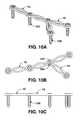
- FIG. 10provides views of one preferred embodiment of the invention, featuring a plurality of compression brackets joined end-to-end via shared fastener retaining portions, and including a branching compression bracket.
- FIG. 11is a side view of a preferred embodiment of a screw type fastener for use in the invention.
- FIG. 12is a side perspective view of a preferred embodiment of a pin-type fastener for use in the invention.
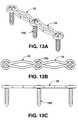
- FIG. 13provides views of one preferred embodiment of the invention, featuring a pair of compression brackets joined end-to-end via a shared fastener retaining portion.
- FIG. 14provides views of one preferred embodiment of the invention.
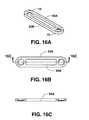
- FIG. 15provides views of one preferred embodiment of the invention.
- FIG. 16provides views of one preferred embodiment of the invention.
- FIG. 17provides views of one preferred embodiment of the invention.
- FIG. 18provides views of one preferred embodiment of the invention.
- FIG. 19provides views of one preferred embodiment of the invention.
- FIG. 20is a perspective view of one embodiment of a drill guide instrument for use in installing the compression brackets of the invention.
- FIG. 21provides perspective views of drivers for use with the drill guide instrument of FIG. 20 .
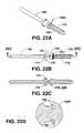
- FIG. 22Ais a side perspective view of one preferred embodiment of the snap-off surgical screw of the invention.
- FIG. 22Bis a side view of one preferred embodiment of the snap-off surgical screw of the invention.
- FIG. 22Cis a cross-section view taken along B-B of FIG. 22B .
- FIG. 22Dis a cross-section view featuring details of one preferred embodiment of a frangible connection of the snap-off surgical screw of the invention.
- FIG. 22Eis a side view of one preferred embodiment of a snap-off screw of the invention, featuring a cross-section view of a quick connect coupling member.
- FIG. 22Fis a top view of a one preferred embodiment of a snap-off screw of the invention, featuring quick connect coupling features.
- FIG. 22Gis a cross-section view taken along A-A of FIG. 22F .
- FIG. 23provides views of a preferred embodiment of a multi-use instrument for holding, impacting and spreading the compression brace of the invention.
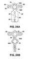
- FIG. 24Ashows a top view of one preferred embodiment of a fracture fixation plate having a compression opening.
- FIG. 24Bshows a top view of one preferred embodiment of a fracture fixation plate having a pair of compression openings.
- FIGS. 25A-25Bshow the use of a fracture fixation plate to reduce a fracture of the radius.
- FIG. 26shows a top view of one preferred embodiment of a fracture fixation plate having a compression opening.
- the inventionis a surgical device for pressing and retaining adjacent bones 301 , 302 against one another, such as to reduce a fracture.
- the inventionincludes, generally, a compression brace 1 and fasteners 100 for securing the brace on bones 301 , 302 .
- compression of the brace 1presses the adjacent bone fragments 301 , 302 together.
- the compression brace 1has at least two fastener retaining portions 10 .
- Each fastener retaining portion 10has a fastener hole or bore 20 therethrough for receiving a fastener 100 .
- a thread 22is provided in the fastener hole 20 .
- the brace 1can be considered to have a tissue or osteo side 2 , which sits against the bones during use, and an opposing side or outer surface 3 .
- the fastener retaining portion 10preferably has a counterbore 30 formed in the outer surface 3 .
- the counterbore 30is preferably substantially in axial alignment with the fastener hole 20 .
- the counterbore 30is preferably spherical.
- the counterbore 30is sized and configured to provide countersinking of an upper retainer portion 150 of a fastener 100 in the fastener retaining portion 10 of the compression brace 1 .
- a pair of bridge members 50 A, 50 Bare positioned between the fastener retaining portions 10 .
- the bridge members 50 A, 50 Bpreferably extend directly from the fastener retaining portions 10 , but may be spaced from one or both of the fastener retaining portions, such as by a shared extension portion disposed between the bridge members 50 A, 50 B and fastener retainer portions 10 .
- the bridge members 50 A, 50 Bare spaced apart from one another to form a compression opening 70 between the fastener retaining portions 10 .
- the bridge members 50 A, 50 B and the compression opening 70are used to compress the fastener retaining portions 10 and fasteners 100 toward one another, in a manner described in further detail below.
- the bridge members 50 A, 50 Bare substantially V-shaped.
- the V-shapeis preferably formed by generally linear portions 51 , 52 , which normally join one another at an obtuse angle when the brace 10 is in an uncompressed configuration.
- central portions of the bridge members 50 A, 50 Bexpand outward, thus drawing or compressing the fastener retaining portions 10 toward one another.
- FIG. 2demonstrates the configuration of the compression brace of FIG. 1 after it has been compressed a selected amount. Note that in FIG.
- the compression brace 1has contracted generally along its lengthwise axis, while the opposing bridge members 50 A, 50 B have expanded in directions generally transverse to the lengthwise axis.
- the bridge members 50 A, 50 Bcan be pinched toward one another. Pinching will tend to force the fastener retaining portions 10 apart, particularly when using a V-shaped opening, which can be useful for certain surgical applications, such as distractions.
- the compression brace 1can be used both for compression and distraction, as well as to provide for fine-tuning of bone gap sizes and compressive forces. Pinching can also be used to force the fastener retaining portions 10 toward one another, resulting in compression.
- Bridge members 50 A, 50 Bmay alternatively have curved, arcuate, straight, or other deformable configurations, provided that bridges 50 A, 50 B are configured to form a deformable compression opening 70 .
- the bridge members 50 A, 50 Bare shortened and form a tighter angle along the compression opening 70 .
- FIG. 6also shows an embodiment in which a chamfer is formed along the upper edge of the compression brace 1 .
- fasteners 100are used to secure the bracket 1 to adjacent bones 301 , 302 .
- Each fastener 100is sized and configured to pass through a fastener hole 20 and to retain the compression bracket 1 on bones 301 , 302 .
- Fasteners 100 of differing diametercan be used. For example, if angulation of the fastener 100 is desired, a smaller diameter may be used.
- the fasteners 100may be locking or non-locking.
- each fastener 100has a lengthwise shaft 110 sized to pass through at least one of the fastener holes 20 , and an upper retainer portion 150 sized and configured to retain the fastener 100 in the fastener hole 20 .
- the retainer portion 150is preferably a circumferential head of the type used in conventional screws.
- the head 150is preferably provided with a self-retaining drive mechanism, such as press-fit drive slots 155 .
- the fastener 100is preferably a screw 100 , in which case the shaft 110 is provided with a lower thread 112 that is positioned to engage bone.
- the lower thread 112is preferably self-tapping and self-drilling in bone.
- a cutting means 115is preferably provided on or adjacent the tip of the screw 100 . Cutting means are well known to those of skill in the art of surgical screws.
- an alternative preferred fastener 100is a pin 100 .
- the pin 100 shown in FIG. 12has an enlarged head or fastener retainer portion 150 configured to retain the pin 100 in the fastener retainer member 10 .
- the shaft 110 of the pin 100preferably has a substantially smooth outer surface.
- an upper thread 120is provided on the shaft 110 adjacent the head of the fastener 100 for use in engaging the internal thread 22 in the fastener hole 20 .
- the upper thread 120 of the fastener 100 and the internal thread 22 of the compression brace 1serve to maintain the fastener 100 in a substantially fixed relation to the fastener retaining portion 10 .
- an upper thread 120has maintained the fasteners 100 in a substantially perpendicular relation to the fastener retainer portion 10 .
- the fasteners 100have maintained a substantially fixed relation even after the compression bracket 1 has been compressed to draw the bones 301 , 302 together.
- a substantially fixed relationshipcan also be obtained by providing a snug-fit screw head appropriately sized to the fastener hole 20 and counterbore 30 .
- the pins of the staplestend to splay outward significantly during use in vivo, decreasing the compressive strength of the staples.
- the inventionmay be provided with a means 130 for selectively locking the fastener 100 in the fastener hole 20 .
- the locking means 130is provided by forming the upper thread 120 from double-lead threads 132 , 133 .
- the double-lead threads 132 , 133provide selective locking of the fastener 100 in the fastener hole 20 via locking interaction with the single internal thread 22 of the fastener hole 20 .
- One advantage of a double-lead type of locking means 130is that the threads can be configured such that the compression bracket 1 can be reused, for example if it becomes necessary to remove and replace or reposition the original fastener 100 .
- Other locking meansinclude mismatched threads.
- the surgical devicemay be configured such that there is play between the fastener 100 and the fastener retaining portion 10 .
- the fastener hole 20 of the brace memberis substantially smooth, i.e. unthreaded.
- the shaft 110 of the fastener 100is sized to provide play between the shaft 100 and the fastener hole 20 . As indicated in FIG. 7 , this configuration allows the fastener 100 to be selectively angled into bone during use of the device.
- Snap-off screwssuch as the type shown in FIG. 22
- the snap-off surgical screw shown in FIG. 22Bis similar to the screws described above in that it has a head 150 , an upper threaded part 120 providing a locking thread 130 distal to the head, and a bore thread 112 distal to the locking thread 130 .
- a shaft extension 160extends above the poly-axial head for use in rotating and driving the screw.
- the shaft extension 160is axially aligned with the screw 100 .
- a distal end of the shaft extension 160is fixedly connected to the head 150 of the screw by a narrow shaft 161 . After the screw 100 is inserted, the shaft 160 is broken off of the screw 100 at the point of the narrow shaft 161 .
- FIGS. 22A-22Gthe present application is directed toward embodiments of a snap-off surgical screw 100 , the basic features of which are described in applicant's U.S. patent application Ser. No. 10/940,396, which is incorporated herein by reference.
- snap-off screws 100 Ssuch as the type shown in FIG. 22
- the snap-off surgical screw shown in FIG. 22Bis similar to the screws described above in that it has a head 150 , an upper threaded part 120 providing a locking thread 130 distal to the head, and a bore thread 112 distal to the locking thread 130 .
- a shaft extension 160extends above the poly-axial head for use in rotating and driving the screw 100 .
- the shaft extension 160is axially aligned with the screw 100 .
- a distal end of the shaft extension 160is fixedly connected to the head 150 of the screw by a narrow shaft 161 . After the screw 100 is inserted, the shaft 160 is broken off of the screw 100 at the point of the narrow shaft 161 .
- the snap-off surgical screw 100 Sis configured for threading into a bone of a patient using a conventional driver or a powered driver, such as a drill or reamer.
- a conventional driver or a powered driversuch as a drill or reamer.
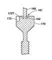
- At least a portion of the shaft extension 160serves as a driver engaging member or portion 170 .
- the driver engaging portion 170is configured for engagement by a chuck of a conventional drill, such as a Jacobs chuck, or by a quick connect coupling member 177 (discussed below).
- the driver engaging portion 170can take various configurations, depending on the type of drill chuck or quick connect coupling member 177 that will be used to engage the driver engaging portion 170 .
- the driver engaging portion 170is joined to the screw portion 100 via a frangible connection 161 .
- the frangible connection 161comprises at least one defect 162 formed through an outer surface of the frangible connection 161 .
- the defect 162is configured to promote selective separation of the driver engaging portion 170 from the screw portion at the defect 162 .
- the defect 162can take various forms, such as a circumferential groove or undercut that is narrower than the shaft extension 160 , a wedge shaped defect, or a plurality of wedge shaped defects spaced circumferentially around the frangible connection 161 .
- the defect 162can be a laser mark etched into the frangible connection 161 .
- the defect 162makes it less likely that fragments of the shaft extension 160 will remain on the screw portion 100 after the shaft extension 160 has been snapped off.
- the frangible connection 161can be configured such that it breaks at a selected torque or within a selected torque range.
- the preferred torque break rangeis about 2 to about 30 N cm based on a thread size of about 1.0 to about 5.0 mm (major diameter).
- a proximal end 100 P of the screw portionhas a recess 190 therein.
- the frangible connection 162is positioned in the recess 190 to thereby configure the shaft extension 160 to snap-off from the screw portion within the recess and below the proximal end 100 P of the screw portion 100 .
- the recess 190thus helps ensure that any fragments of the shaft extension 160 that may remain on the screw portion 100 after the shaft extension 160 has been snapped off will lie below the proximal end 100 P of the screw portion 100 , where the fragments are less likely to irritate soft tissue.
- the lengthwise shaft 110 of the snap-off screw 100 Scan be provided with various types and combinations of threads and thread features, such as a self-drilling thread or a self-tapping tip.
- the driver engaging portion 170 of the shaft extension 160can be provided with various means for providing a connection between the snap-off screw 100 S and a driver, such as drill or reamer.
- a driversuch as drill or reamer.
- Conventional breakaway screwsrely on a conventional chuck, such as a Jacobs chuck, to attach the screw to a driver.
- the connection processcan be time consuming, particularly when it is necessary to install multiple breakaway screws.
- one aspect of the inventionis a quick connect coupling member 177 .
- the quick connect coupling member 177is configured for connection to the chuck of a driver, such as by a Jacobs chuck.
- the quick connect coupling 177includes engagement features 178 that allow the quick connect coupling to quick-connect to the driver engaging portion 170 . As indicated in FIG.
- the driver engaging portion 170 of the shaft extension 160in turn includes features that enable the snap-off screw 100 S to quick connect to the quick connect coupling 177 .
- the use of a quick connect coupling member 177 and matching quick connect features 172 on the driver engaging portion 170eliminates the need to use a chuck to connect each screw 100 S to a driver. This feature of the invention is particularly beneficial when using multiple snap-off screws 100 S in a single procedure.
- the driver engaging portion 170 of the shaft extension 160includes a pair of indents or apertures 172 that are spaced to engage ball detents 178 in a quick connect coupling member 177 .
- the matching quick connect coupling member 177includes spring biased ball detents 178 positioned in a bore.
- the driver engaging portion 170 of the shaft extension 160is an enlarged driver head 170 .
- the enlarged driver head 170is provided with a plurality of slots 172 for receiving matching prongs 178 .
- the prongs 178could be on a screw driver or on a quick connect coupling member 177 .
- the enlarged driver head 170includes three substantially equidistant slots 172 in order to provide a 3-point driving mechanism.
- the 3-point driving mechanismprovides a positive fit with the screw 100 S to ensure that the screw stays concentric with the driver during insertion.
- the driver engaging portion 170also preferably includes a non-circumferential portion, such as a flat 171 , which serves to orient the slots 172 for engagement by the quick connect coupling member 177 as well as to maintain the shaft extension 160 and the driver in a fixed, non-rotating relationship.
- the slots 172preferably include at least one tapered wall 172 T, to assist in seating the quick coupling member 177 .
- Prior art couplingsdo not employ a tapered wall, and consequently must provide a degree of clearance between the driver tabs and the slots, which results in a looser fit. With a tapered slot 172 T and tapered driver, the driver and slot 172 wedge together, resulting in a better fit.
- An enlarged driver head 170 having slots 172can also be provided as the head 150 of the screw portion 100 .
- FIGS. 14-17provide views of various embodiments of compression brackets 1 of the invention.
- the bracket shown in FIGS. 14A-14Chas an elongated compression opening 70 .
- FIGS. 15A-15Cshow a compression bracket 1 having a spaced apart bridge members 50 A, 50 B, such that the opposing ends of the bridge members 50 A, 50 B are not directly adjacent one another.
- FIGS. 16A-16Cshow a compression bracket 1 having spaced apart bridge members 50 A, 50 B. Additionally, the spaced apart bridge members 50 A, 50 B of FIG. 16 are straight, and thus lack the V-shaped configuration of other embodiments.
- the bracket shown in FIGS. 17A-17Chas a straight and generally narrow compression opening 70 , but is provided with diametrically opposed distal curved portions for use in engaging the bridge members 50 A, 50 B during spreading of the compression opening 70 .
- FIGS. 18A-18Cshow yet another embodiment in which the opposing bridge, and hence the compression opening 70 , are eliminated in favor of a single bridge 50 .
- the single bridge 50can be bent in order to draw the opposing fastener retaining portions 10 together.
- the embodiment shown in FIGS. 18A-18Ccan be provided with the various threaded and unthreaded variations described above.
- FIGS. 19A-19Dshow an embodiment that combines the features of prior art surgical staples with the advantages provided by the compression bracket 1 of the present invention.
- the combined staple-compression bracketincludes opposing bridge members 50 A, 50 B and a fastener retaining portion 10 having the configuration and characteristics described above.
- the opposing end of the deviceis provided with a downwardly depending leg 200 .
- the downwardly depending leg 200is preferably provided with means for securing the leg 200 in bone, such as the proximal 201 and distal 202 teeth or serrations shown in FIG. 19C .
- the compression bracket 1can include a plurality of fastener retaining portions 10 and a plurality of compression openings 70 .
- a pair of compression bracketsare joined end-to-end in a unitary or unibody compression bracket structure.
- FIGS. 13A-Cshow an end-to-end configuration in which bridge members 50 A, 50 B are joined by a shared fastener retaining portion 10 .
- FIGS. 9A-9Ca plurality of bridge members 50 A, 50 B radiate from a shared fastener retaining portion 10 .
- FIGS. 9A-9Ca plurality of bridge members 50 A, 50 B radiate from a shared fastener retaining portion 10 .
- FIG. 10also includes a compression bracket that branches off from the main chain via a shared fastener retaining portion 10 .
- Multi-part compression bracketscan also be configured to include adjacent compression openings that are not separated by a fastener retaining member 20 .
- Multi-compression bracketssuch as those shown in FIGS. 8-10 are particularly suited for fixation or distraction of multi-part fractures, such as when a bone fractures into more than two fragments.
- the multi-compression bracket embodiments shown in FIGS. 8-10are merely exemplary preferred embodiments of the invention, and are intended to provide those with skill in the art with the building blocks necessary to configure a wide variety of multi-compression bracket configurations, all of which would fall within the scope of the invention.
- compression braces 1can be provided with a combination of threaded and unthreaded holes. Such a configuration could be used, for example, in situations where it is desirable to provide a perpendicularly locked fastener on one end of the brace 1 , while providing selective angulation of the fastener 100 on the opposing end of the brace.
- the compression brace 1is used primarily for fixation of arthrodeses and osteotomies.
- the compression brace 1can also be used in place of conventional plates, such as cuboid plates, hind or mid-foot plates, or calcaneal plates.
- FIG. 24Ashows a fracture fixation plate 80 that has a compression opening 70 along a distal portion of the plate, such as the metaphyseal regions of the plate.
- the plate 80has a pair of metaphyseal or distal plate portions 82 disposed along a compression opening 70 .
- the plate 80 of FIG. 24Aalso includes a diaphyseal or proximal plate portion 84 disposed along a proximal side of the compression opening 70 .
- the plate portions 82 , 84are provided with one or more fastener holes 20 for use in securing the metaphyseal plate portion 82 to a bone of the patient using fasteners, such as the types of fasteners discussed herein.
- the plates 82 , 84can also be provided with slots 87 , which are used in a manner known to those of skill in the art of plate fixation.
- the distal compression opening 70can be expanded to draw the distal plate portions 82 toward one another, and thus reduce a fracture. As with the compression braces 1 described herein, the compression openings 70 can be used to selectively expand or compress the openings for fine tuning of the fracture fixation plates 80 and underlying fractures.
- FIG. 24Bshows a fracture fixation plate 80 that has a first or distal compression opening 70 along a distal portion of the plate 80 , and a second or proximal compression opening 70 located closer to a proximal end of the plate 80 , such as in a diaphyseal region of the plate 80 .
- the fracture fixation plate 80 of FIG. 24Bincludes a proximal plate portion 84 for use in securing a proximal portion of the plate 80 to a bone of the patient.
- the fracture fixation plate 80 of FIG. 24Balso includes an intra-opening plate 83 having at least one fastener hole 20 therethrough.
- the distal compression opening 70can be expanded to force the proximal plate 84 proximally to thereby extend the fracture, or compressed to reduce the fracture. Additionally, note that the use of a second compression opening 70 makes it possible to eliminate slots 87 from the plate 80 while retaining the capability of expanding a fracture.
- FIGS. 25A-25Bshow the use of a fracture fixation plate 80 to reduce an intra-articular fracture of the distal radius while simultaneously expanding a metaphyseal region to a pre-fracture length.
- another advantage of the fracture fixation plate 80is that the compression opening 70 of the compression plate 80 can be used to compress intra-articular fragments of an intra-articular fracture F 1 securely against one another, so as to substantially eliminate gaps in the articular surface. Under the prior art, intra-articular fragments had to be manually reduced and then secured together with screws.
- FIG. 25Ashows a distal radius fracture in which the injury has resulted in a reduction in the length of the radius along the metaphyseal fracture F 2 .
- the expanded metaphyseal fracture F 2can be filled with an osteoconductive material, such as OSTEOSET® pellets (available from Wright Medical Technology, Inc. of Arlington, Tenn.), to promote healing of the fracture F 2 and restoration of normal radius length.
- OSTEOSET® pelletsavailable from Wright Medical Technology, Inc. of Arlington, Tenn.
- FIGS. 24-25depict a fracture fixation plate 80 that is particularly configured for use as a dorsal or volar fracture fixation plate on the distal radius
- the concept of combining compression openings with fracture fixation platescan be applied to virtually any fracture or bone, provided that the compression opening 70 is sufficiently strong to maintain sufficient reduction to allow for healing of the particular fracture.
- FIG. 26shows a fracture fixation plate 80 that is configured primarily for use on the diaphysis of long bones.
- the plate 80includes a first plate portion 82 and a second plate portion 84 , with the plate portions 82 , 84 joined together by the opposing bridges 50 A, 50 B of a compression opening 70 .
- the compression brace 1is used as follows. After preparation of the surgical site, the compression brace 1 is placed on adjacent bones 301 , 302 such that one of the fastener holes is on the first bone or bone fragment 301 and one of the fastener holes 302 is on the second bone or bone fragment (see FIG. 4 ).
- the first and second bones 301 , 302may of course be fragments or segments of the same bone, i.e. after fracture.
- the compression brace 1is secured on the first bone 301 by inserting a fastener 100 through one of the fastener holes 20 and into the first bone 301 .
- the compression brace 1is secured to the second bone 302 by inserting a fastener 100 through one of the fastener holes 20 and into the second bone.
- the bridge members 50 A, 50 B of the compression brace 1are then spread apart to draw the fasteners 100 and the bones 301 , 302 toward one another.
- sufficient forcecan be applied to press adjacent bones 301 , 302 against one another to substantially eliminate a gap 300 between the bones 301 , 302 .
- sufficient forcecan be applied to move the bones 301 , 302 toward one another a selected distance, but without removing the gap 300 .
- more than one compression brace 1can be used to fix the fracture.
- a multi-compression bracketsuch as the embodiments shown in FIGS. 8-10 can be used to fix the various bone fragments.
- holesare drilled into the bones 301 , 302 through the fastener holes 20 , and the fasteners 100 are then installed in the drilled holes. Pre-drilling is unnecessary if self-drilling fasteners 100 are used.
- the compression bracket 1can also be used as a distraction plate, such as for opening osteotomies (e.g. HTO or spine distraction).
- a distraction platesuch as for opening osteotomies (e.g. HTO or spine distraction).
- FIG. 20shows a preferred drill guide instrument 300 for use in installing the compression braces 1 .
- the drill guide 300includes a handle or mounting arm 310 having an extension portion 312 .
- a stationary guide base 318is fixedly mounted on an upper end of the extension portion 312 .
- an adjustable guide base 328is slidably and adjustably engaged to the stationary guide base 318 via an adjustment member 320 having a lengthwise opening 321 therethrough.
- a locking means 312is provided for selectively locking the adjustable guide base 328 relative to the stationary guide base 318 .
- the locking meansis a ring 330 threaded on the extension portion 312 .
- a first drill guide 301is fixedly mounted on the stationary guide base 318
- a second drill guide 302is fixedly mounted on the adjustable guide base 328 .
- the drill guides 301 , 302are preferably removable from the drill guide instrument in order to accommodate selected sizes and configurations of fasteners 100 and compression braces 1 .
- a distal end of the drill guide 301 , 302is provided with a counter bore having a side slot 304 therethrough for accommodating a compression brace 1 , in the manner shown in FIG. 20 .
- each drill guide 301 , 302has a lengthwise cylindrical sleeve (not shown) passing therethrough.
- the sleevesare sized to receive and provide rotational guidance to driver components such as drill bit 380 (preferred embodiment shown in FIG. 21A ) or a screwdriver 390 (preferred embodiment shown in FIG. 21B ).
- the driver components 380 , 390have a cylindrical shaft portion 384 sized to permit guided rotation within the drill guides 301 , 302 .
- a stop 386is provided on the shaft 384 .
- the stop 386is sized and positioned to abut against the drill guide 301 , 302 , the guide base 318 , 328 or another selected portion of the drill guide instrument 300 to prevent over drilling.
- the drive components 380 , 390are provided with a conventional 388 mount on an upper end for selective engagement with a drive means, in a manner known to those of skill in the art.
- the drill bit driver component 380is provided with a drill bit 381 .
- the screw driver component 390is provided with a screw driver head 391 configured to match the fasteners 100 .
- Various sizes and types of drill bits 381 and screwdrivers 391can be used with the drill guide instrument 300 , depending on intra-operative conditions.
- a tamping driver(not shown) can be provided for inserting pins 100 with the drill guide instrumentation 300 .
- the drill guide instrument 300can be adjusted to the size of a selected compression brace 1 simply by sliding the second drill guide 302 relative to the first drill guide 301 until a suitable position is reached, and then locking the second drill guide 302 in place via the locking means 330 .
- the drill guide instrument 300aligns the axes of the driver components 380 , 390 with those of the fastener holes 20 , which enables precise drilling or threading of fastener screws 100 .
- Spreading of the bridge members 50 A, 50 Bis preferably accomplished using a spreader, such as the type shown in FIG. 10 of U.S. Pat. No. 5,660,188 (Groiso). If crimping of the bridge members 50 A, 50 B is desired, pliers can be used.
- FIGS. 23A-23Eshow one preferred embodiment of a multi-use spreader 400 that combines these three functions into a single instrument. As a result, not only are fewer instruments required, but also fewer surgical steps, which allows for simpler and more efficient surgical techniques.
- the multi-use spreader 400 shown in FIG. 23Aincludes, generally, an impactor handle 410 pivotally connected to a spreader handle 420 , and a biasing means 430 for normally biasing opposing jaws 418 , 428 of the spreader 400 apart from one another.
- a pair of teeth 418 , 428are formed on distal ends of the jaws 418 , 428 , and are configured for insertion into the compression opening of a compression member, such as the compression braces 1 described herein or the prior art compression staples. Because the jaws 418 , 428 are normally spread apart, the teeth 419 , 429 abut against the inner sides of the bridges of the compression opening under tension, and thus serve to hold the compression member on the multi-use spreader 400 .
- the multi-use spreader 400can be used to hold the compression member over a selected spot, such as for inserting fasteners 100 into a compression brace 1 or for inserting the legs of a conventional compression staple into predrilled holes.
- the multi-use spreader 400can preferably be readily disassembled for cleaning and repair, and can preferably be autoclaved.
- a proximal end of the impactor handle 410is preferably configured for use as an impact surface.
- an impactor head 412is preferably formed on the proximal end of the impactor handle 410 .
- the impactor head 412has a generally mushroom or bulging configuration that provides a platform for use in impacting the impactor handle 410 with a conventional impactor. With a compression member held firmly by the spreader teeth 419 , 429 , the impactor head 412 can be impacted to drive the spreader teeth into bone, and particularly into pre-drilled holes.
- the impactor handle 410 shown in the preferred embodiment of FIG. 23Aincludes a pivot support 416 extending from the impactor handle 410 . As indicated in FIG. 23C , the pivot support 416 is positioned and configured to pivotally engage a pivot support 426 on the spreader handle 420 .
- a pivot means 440such as a bar 440 , provides a hinge-type pivot between the impactor handle 410 and the spreader handle 420 .
- the impactor handle 410may be provided with a depression or space 417 that is positioned and configured to allow the space 417 to receive a portion of the spreader handle 420 .
- the plunger handle 410maybe provided with a plunger bore 413 .
- the plunger bore 413is located distal to the pivot point 440 , in the jaw portion 418 of the impactor handle 410 .
- FIG. 23Eprovides a cross-section view of a preferred biasing means comprising a spring-biased plunger 430 that is disposed in the plunge bore 413 .
- the spring-biased plunger 430includes a plunger portion 432 , a compression spring 434 , and a retainer plug 436 .
- the plunger portion 432is preferably a round nose ball plunger. As indicated in FIG.
- the spring 434 and retainer plug 436normally bias the plunger 432 in an open position.
- a tip of the plunger 432is configured to extend from the plunger bore 413 such that the tip of the plunger 432 impinges on and opens the jaw portion 428 of the spreader handle 420 .
- the plunger 432includes a shoulder that is configured to abut against a step-down in the plunger bore 413 , and thus to define a maximum biased-open position for the jaws 418 , 428 while also retaining the plunger 432 in a biased condition in the plunger bore 413 .
- the jaws 418 , 428are shown in a closed position in which that the tip of the plunger 430 has been forced into the plunger bore 413 by the inner surface of the jaw 428 of the spreader handle 420 .
- the jaws 418 , 428can be spread apart to deform the bridges of a compression member.
- the impactor handle 410is preferably provided with a lengthwise slot 415 .
- the impactor slot 415serves to lighten the spreader 400 , and can be configured to redistribute the center of gravity, such as to make the device head light.
- the impactor slot 415can also serve as finger hold for the surgeon, which assists in preventing the instrument from slipping in the hands of the surgeon, who may be holding the device with wet surgical gloves. These features make it easier to maneuver and position the instrument 400 during surgery.
- each of the jaw portions 418 , 428are preferably provided with a generally flattened impact shoulder 418 A, 428 A.
- the opposing impact shoulders 418 A, 428 Aprovide a surface for retaining and supporting compression members of various sizes during holding, and for driving compression members of various sizes during impaction.
- each jaw 418 , 428is provided with a tooth member, which can be referred to as an impactor tooth 419 and a spreader tooth 429 , respectively.
- a tooth memberwhich can be referred to as an impactor tooth 419 and a spreader tooth 429 , respectively.
- the teeth 419 , 429are preferably positioned on an inner side of the respective jaws 419 , 429 so as to abut or nearly abut against one another when the instrument is in a closed configuration.
- Each tooth 419 , 429is configured to hold the opposing bridges of a compression member.
- the teeth 419 , 429are preferably relatively narrow so as to enable the teeth 419 , 429 to engage and spread a plurality of sizes of compression members.
- each tooth 419 , 429may be configured to include a bridge engaging portion 419 A, 429 A which generally extends outward in a curved or curvilinear fashion to accommodate the bend in the bridges of compression members.
- the device and methodcan be used to join, fix and maintain bones in various procedures, including: LisFranc arthrodesis; mono or bi-cortical osteotomies in the forefoot; first metatarsophalangeal arthrodesis; Akin osteotomy; midfoot and hindfoot arthrodeses or osteotomies; fixation of osteotomies for hallux valgus treatment (Scarf and Chevron); and arthrodeses of the metatarsocuneiform joint to reposition and stabilize the metatarsus primus varus; carpal bone fusion; wrist fusion; elbow fracture; and metacarpal fractures.
- the compression brace 1 and fasteners 100are preferably made of suitable biocompatible materials having sufficient mechanical strength and elasticity for the desired applications of the invention 1 .
- suitable materialsinclude medical grade titanium alloys, medical grade stainless steel, and cobalt chrome.
- a memory metal, such as nitinol,can be incorporated into the invention.
- Suitable non-metallic biocompatible materialscan also be used.
- the brace 1 or fasteners 100can be made of a suitable bio-absorbable material, such that the components are eventually absorbed by the body after healing of the bone parts.
- boneas used herein includes whole bones as well as bone fragments (i.e. the two or more fragments of a particular bone that remain after the bone has been fractured, either completely or incompletely).
Landscapes
- Health & Medical Sciences (AREA)
- Orthopedic Medicine & Surgery (AREA)
- Surgery (AREA)
- Life Sciences & Earth Sciences (AREA)
- Biomedical Technology (AREA)
- Public Health (AREA)
- Veterinary Medicine (AREA)
- Engineering & Computer Science (AREA)
- Nuclear Medicine, Radiotherapy & Molecular Imaging (AREA)
- Heart & Thoracic Surgery (AREA)
- Medical Informatics (AREA)
- Molecular Biology (AREA)
- Animal Behavior & Ethology (AREA)
- General Health & Medical Sciences (AREA)
- Neurology (AREA)
- Dentistry (AREA)
- Oral & Maxillofacial Surgery (AREA)
- Surgical Instruments (AREA)
Abstract
Description
Claims (21)
Priority Applications (6)
| Application Number | Priority Date | Filing Date | Title |
|---|---|---|---|
| US10/940,396US20060058796A1 (en) | 2004-09-14 | 2004-09-14 | Compression brace |
| US11/060,965US8221478B2 (en) | 2004-09-14 | 2005-02-18 | Snap-off surgical screw |
| PCT/US2005/032333WO2006031692A2 (en) | 2004-09-14 | 2005-09-09 | Snap-off surgical screw |
| US12/582,210US20100036430A1 (en) | 2004-09-14 | 2009-10-20 | Compression brace |
| US14/172,547US20140316470A1 (en) | 2004-09-14 | 2014-02-04 | Compression brace |
| US14/329,429US20150012004A1 (en) | 2004-09-14 | 2014-07-11 | Compression brace |
Applications Claiming Priority (2)
| Application Number | Priority Date | Filing Date | Title |
|---|---|---|---|
| US10/940,396US20060058796A1 (en) | 2004-09-14 | 2004-09-14 | Compression brace |
| US11/060,965US8221478B2 (en) | 2004-09-14 | 2005-02-18 | Snap-off surgical screw |
Related Parent Applications (1)
| Application Number | Title | Priority Date | Filing Date |
|---|---|---|---|
| US10/940,396Continuation-In-PartUS20060058796A1 (en) | 2004-09-14 | 2004-09-14 | Compression brace |
Publications (2)
| Publication Number | Publication Date |
|---|---|
| US20060081553A1 US20060081553A1 (en) | 2006-04-20 |
| US8221478B2true US8221478B2 (en) | 2012-07-17 |
Family
ID=35515598
Family Applications (5)
| Application Number | Title | Priority Date | Filing Date |
|---|---|---|---|
| US10/940,396AbandonedUS20060058796A1 (en) | 2004-09-14 | 2004-09-14 | Compression brace |
| US11/060,965Active2030-01-19US8221478B2 (en) | 2004-09-14 | 2005-02-18 | Snap-off surgical screw |
| US12/582,210AbandonedUS20100036430A1 (en) | 2004-09-14 | 2009-10-20 | Compression brace |
| US14/172,547AbandonedUS20140316470A1 (en) | 2004-09-14 | 2014-02-04 | Compression brace |
| US14/329,429AbandonedUS20150012004A1 (en) | 2004-09-14 | 2014-07-11 | Compression brace |
Family Applications Before (1)
| Application Number | Title | Priority Date | Filing Date |
|---|---|---|---|
| US10/940,396AbandonedUS20060058796A1 (en) | 2004-09-14 | 2004-09-14 | Compression brace |
Family Applications After (3)
| Application Number | Title | Priority Date | Filing Date |
|---|---|---|---|
| US12/582,210AbandonedUS20100036430A1 (en) | 2004-09-14 | 2009-10-20 | Compression brace |
| US14/172,547AbandonedUS20140316470A1 (en) | 2004-09-14 | 2014-02-04 | Compression brace |
| US14/329,429AbandonedUS20150012004A1 (en) | 2004-09-14 | 2014-07-11 | Compression brace |
Country Status (2)
| Country | Link |
|---|---|
| US (5) | US20060058796A1 (en) |
| WO (1) | WO2006031692A2 (en) |
Cited By (10)
| Publication number | Priority date | Publication date | Assignee | Title |
|---|---|---|---|---|
| US8956361B2 (en) | 2011-12-19 | 2015-02-17 | Amendia, Inc. | Extended tab bone screw system |
| US8992586B2 (en) | 2011-07-20 | 2015-03-31 | Michael H. Horwitz | Minimal incision removable bone screw, driver, and method of use |
| US9138219B2 (en) | 2010-12-29 | 2015-09-22 | Tarsus Medical Inc. | Methods and devices for treating a syndesmosis injury |
| US9480513B2 (en) | 2011-03-02 | 2016-11-01 | Hipp Medical Ag | Clamping element for setting a bone fracture as well as modular fixation device comprising same and method for producing same |
| US20170172634A1 (en)* | 2014-03-13 | 2017-06-22 | Mx Orthopedics, Corp. | Plates for generating, applying and maintaining compression within a body |
| US9855036B2 (en) | 2013-11-13 | 2018-01-02 | Arthrex, Inc. | Staples for generating and applying compression within a body |
| US9861413B2 (en) | 2013-11-11 | 2018-01-09 | Arthrex, Inc. | Screws for generating and applying compression within a body |
| US10016198B2 (en) | 2014-11-13 | 2018-07-10 | Arthrex, Inc. | Staples for generating and applying compression within a body |
| US10898249B2 (en) | 2015-01-28 | 2021-01-26 | Arthrex, Inc. | Self-compressing screws for generating and applying compression within a body |
| US11540898B2 (en) | 2018-09-21 | 2023-01-03 | Nexxt Spine, LLC | Bone screw with frangible tracking tag |
Families Citing this family (109)
| Publication number | Priority date | Publication date | Assignee | Title |
|---|---|---|---|---|
| US8475504B2 (en)* | 2007-07-19 | 2013-07-02 | Acumed Llc | Method of bone fixation with slender spanning members disposed outside bone |
| EP1708629A4 (en)* | 2004-01-08 | 2011-08-17 | David Mark Allison | Bone fixing device |
| US20060243340A1 (en)* | 2005-03-22 | 2006-11-02 | Wheeler Dennis L | Apparatus and method for attaching fencing material |
| US7993380B2 (en)* | 2005-03-31 | 2011-08-09 | Alphatel Spine, Inc. | Active compression orthopedic plate system and method for using the same |
| EP1764042A3 (en)* | 2005-09-12 | 2009-08-26 | Arthrex, Inc. | Compression staple |
| US9119677B2 (en) | 2005-12-09 | 2015-09-01 | DePuy Synthes Products, Inc. | Spinal plate and drill guide |
| TWM309620U (en)* | 2006-01-09 | 2007-04-11 | Yea Jann Ind Co Ltd | Needle nail |
| US7901431B2 (en)* | 2007-01-17 | 2011-03-08 | Arthrex, Inc. | Lisfranc repair using suture-button construct |
| US8920479B2 (en)* | 2007-03-30 | 2014-12-30 | K2M, Inc. | Anterior vertebral plate with spike fixation |
| FR2916954B1 (en)* | 2007-06-05 | 2011-11-25 | Small Bone Innovations Internat | OSTEOSYNTHESIS CLIP |
| US7604640B2 (en)* | 2007-06-14 | 2009-10-20 | Zimmer Spine Austin, Inc. | Device and system for applying rotary impact |
| GB0712247D0 (en)* | 2007-06-25 | 2007-08-01 | I J Smith & Nephew Ltd | Medical device |
| WO2009039513A1 (en)* | 2007-09-20 | 2009-03-26 | Pivot Medical, Inc. | Method and apparatus for re-attaching the labrum of a hip joint |
| EP2397094B1 (en) | 2007-11-02 | 2013-06-26 | Biomet C.V. | Elbow fracture fixation system |
| US20090131984A1 (en)* | 2007-11-19 | 2009-05-21 | Linares Miguel A | Spine support implant including inter vertebral insertable fluid ballastable insert and inter-vertebral web retaining harnesses |
| US20220175372A1 (en)* | 2008-02-15 | 2022-06-09 | Cilag Gmbh International | Releasable layer of material and surgical end effector having the same |
| US8257403B2 (en)* | 2008-02-19 | 2012-09-04 | Orthohelix Surgical Designs, Inc. | Orthopedic plate for use in the midfoot |
| US8167918B2 (en)* | 2008-02-19 | 2012-05-01 | Orthohelix Surgical Designs, Inc. | Orthopedic plate for use in the MTP joint |
| US8257406B2 (en) | 2008-02-19 | 2012-09-04 | Orthohelix Surgical Designs, Inc. | Orthopedic plate for use on a single ray in the midfoot |
| EP2296567B1 (en)* | 2008-06-06 | 2014-03-12 | Simpirica Spine, Inc. | Apparatus for locking a band |
| FR2936700B1 (en) | 2008-10-02 | 2012-04-13 | Memometal Technologies | ORTHOPEDIC IMPLANT IN THE FORM OF A PLATE TO BE FIXED BETWEEN TWO BONE PARTS |
| US12285197B2 (en) | 2008-10-10 | 2025-04-29 | Acumed Llc | Bone fixation system with opposed mounting portions |
| IT1392434B1 (en)* | 2008-12-23 | 2012-03-09 | Orthofix Srl | ORTHOPEDIC DEVICE TO ENCOURAGE THE RIGID FRACTURE OSTEOSYNTHESIS |
| US8870876B2 (en)* | 2009-02-13 | 2014-10-28 | Tarsus Medical Inc. | Methods and devices for treating hallux valgus |
| USD623744S1 (en) | 2009-02-17 | 2010-09-14 | Orthohelix Surgical Designs, Inc. | Orthopedic plate |
| USD623745S1 (en) | 2009-02-17 | 2010-09-14 | Orthohelix Surgical Designs, Inc. | Orthopedic plate |
| USD623743S1 (en) | 2009-02-17 | 2010-09-14 | Orthohelix Surgical Designs, Inc. | Orthopedic plate |
| US8435265B2 (en) | 2009-03-18 | 2013-05-07 | Depuy Spine, Inc. | Laminoplasty methods using hinge device |
| DE102010016812A1 (en)* | 2009-06-08 | 2011-03-17 | Z.-Medical Gmbh & Co. Kg | bone screw |
| US8986353B2 (en) | 2009-07-09 | 2015-03-24 | Orthohelix Surgical Designs, Inc. | Osteotomy plate, plate driver and method for their use |
| US10238379B2 (en) | 2009-07-17 | 2019-03-26 | Pivot Medical, Inc. | Method and apparatus for attaching tissue to bone, including the provision and use of a novel knotless suture anchor system |
| US9179905B2 (en) | 2009-07-17 | 2015-11-10 | Pivot Medical, Inc. | Method and apparatus for re-attaching the labrum to the acetabulum, including the provision and use of a novel suture anchor system |
| US11197663B2 (en) | 2009-07-17 | 2021-12-14 | Stryker Puerto Rico Limited | Method and apparatus for attaching tissue to bone, including the provision and use of a novel knotless suture anchor system |
| US10058319B2 (en) | 2009-07-17 | 2018-08-28 | Pivot Medical, Inc. | Method and apparatus for attaching tissue to bone, including the provision and use of a novel knotless suture anchor system, including a novel locking element |
| US12232718B2 (en) | 2009-07-17 | 2025-02-25 | Stryker Puerto Rico Limited | Method and apparatus for attaching tissue to bone, including the provision and use of a novel knotless suture anchor system |
| US10136884B2 (en) | 2009-07-17 | 2018-11-27 | Pivot Medical, Inc. | Method and apparatus for attaching tissue to bone, including the provision and use of a novel knotless suture anchor system, including a retractable sheath |
| US9149268B2 (en) | 2009-07-17 | 2015-10-06 | Pivot Medical, Inc. | Method and apparatus for attaching tissue to bone, including the provision and use of a novel knotless suture anchor system |
| US10426456B2 (en) | 2009-07-17 | 2019-10-01 | Pivot Medical, Inc. | Method and apparatus for re-attaching the labrum to the acetabulum, including the provision and use of a novel suture anchor system |
| US11246585B2 (en) | 2009-07-17 | 2022-02-15 | Stryker Puerto Rico Limited | Method and apparatus for attaching tissue to bone, including the provision and use of a novel knotless suture anchor system |
| US9066757B2 (en)* | 2009-08-10 | 2015-06-30 | Virak Orthopedic Research Llc | Orthopedic external fixator and method of use |
| US8282636B2 (en)* | 2009-08-10 | 2012-10-09 | Imds Corporation | Orthopedic external fixator and method of use |
| US8277459B2 (en)* | 2009-09-25 | 2012-10-02 | Tarsus Medical Inc. | Methods and devices for treating a structural bone and joint deformity |
| US8568417B2 (en) | 2009-12-18 | 2013-10-29 | Charles River Engineering Solutions And Technologies, Llc | Articulating tool and methods of using |
| ES2525129T3 (en) | 2009-12-30 | 2014-12-17 | Medartis Ag | Osteosynthesis plate for the treatment of fractures near a joint or osteotomies |
| US8652141B2 (en) | 2010-01-21 | 2014-02-18 | Tarsus Medical Inc. | Methods and devices for treating hallux valgus |
| US20110218580A1 (en)* | 2010-03-08 | 2011-09-08 | Stryker Trauma Sa | Bone fixation system with curved profile threads |
| WO2011119815A2 (en)* | 2010-03-26 | 2011-09-29 | The General Hospital Corporation | System and methods for in vivo adjustable bone plate |
| US8647369B2 (en) | 2010-05-19 | 2014-02-11 | Josef E. Gorek | Minimal profile anterior bracket for spinal fixation |
| US8696719B2 (en) | 2010-06-03 | 2014-04-15 | Tarsus Medical Inc. | Methods and devices for treating hallux valgus |
| US8790379B2 (en) | 2010-06-23 | 2014-07-29 | Zimmer, Inc. | Flexible plate fixation of bone fractures |
| EP3639775B1 (en) | 2010-06-23 | 2024-07-17 | Zimmer, Inc. | Flexible plate fixation of bone fractures |
| AU2016203422B2 (en)* | 2010-06-23 | 2017-03-30 | Zimmer, Inc | Flexible plate fixation of bone fractures |
| US8753380B2 (en) | 2010-08-02 | 2014-06-17 | Tongji University | Separable pedicle screw |
| US20120191104A1 (en)* | 2011-01-21 | 2012-07-26 | Jost Reto | Depth Probe for the Humeral Head |
| WO2012155003A1 (en)* | 2011-05-10 | 2012-11-15 | Peter Nakaji | Cranial plating and bur hole cover system |
| CN103917183A (en) | 2011-06-29 | 2014-07-09 | 皮沃特医疗公司 | Method and apparatus for re-attaching the labrum to the acetabulum, including the provision and use of a novel suture anchor system |
| US9907558B2 (en) | 2011-07-08 | 2018-03-06 | Smith & Nephew, Inc. | Osteotomy guide and method |
| US9451957B2 (en) | 2011-07-27 | 2016-09-27 | William Casey Fox | Bone staple extrusion instrument and method of use and manufacturing |
| US10512459B2 (en) | 2011-07-27 | 2019-12-24 | William Casey Fox | Bone staple, instrument and method of use and manufacturing |
| WO2013049849A2 (en) | 2011-09-30 | 2013-04-04 | Acute Innovations, Llc, An Oregon Limited Liability Company | Bone fixation system with opposed mounting portions |
| HK1201138A1 (en)* | 2011-10-10 | 2015-08-28 | William Casey Fox | Shape changing bone implant for enhanced healing |
| US8551143B2 (en) | 2011-10-11 | 2013-10-08 | Brent Lane Norris | Low profile periarticular tension band plating system with soft tissue neutralization cable tunnel/channel |
| US11123117B1 (en) | 2011-11-01 | 2021-09-21 | Nuvasive, Inc. | Surgical fixation system and related methods |
| US9295508B2 (en) | 2012-02-03 | 2016-03-29 | Zimmer, Inc. | Bone plate for elastic osteosynthesis |
| US10405903B1 (en)* | 2012-05-04 | 2019-09-10 | Xtraverse, LLC | Fasteners with shape changing zigzag structures and methods using same |
| DE102012105125B3 (en)* | 2012-06-13 | 2013-08-14 | Hipp Medical Ag | Clamping element for fixing fractured ends of bone of a bone fracture |
| US8998904B2 (en) | 2012-07-17 | 2015-04-07 | Fastforward Surgical Inc. | Winged tether plate and method of use for reducing angular bone deformity |
| EP2887896B1 (en)* | 2012-08-23 | 2017-04-19 | Synthes GmbH | Bone implant |
| US9452005B2 (en) | 2012-08-23 | 2016-09-27 | DePuy Synthes Products, Inc. | Bone fixation system |
| CN104736081B (en)* | 2012-08-23 | 2017-07-28 | 新特斯有限责任公司 | Bone fixation system |
| US10004603B2 (en) | 2012-08-23 | 2018-06-26 | DePuy Synthes Products, Inc. | Bone implant |
| US9949744B2 (en)* | 2012-08-30 | 2018-04-24 | Wright Medical Technology, Inc. | Implant suitable for calcaneal osteotomy |
| US20140180348A1 (en)* | 2012-12-21 | 2014-06-26 | Wright Medical Technology, Inc. | Trajectory guide |
| US10258378B2 (en) | 2013-03-15 | 2019-04-16 | Dne, Llc | External bone fixation system |
| US9370380B2 (en) | 2013-03-15 | 2016-06-21 | Dne, Llc | External bone fixation system |
| US9517097B2 (en)* | 2013-04-17 | 2016-12-13 | Stc.Unm | Low-profile, high tension mesh plate for subcutaneous fracture fixation |
| US10292694B2 (en) | 2013-04-22 | 2019-05-21 | Pivot Medical, Inc. | Method and apparatus for attaching tissue to bone |
| EP3021773B1 (en) | 2013-07-16 | 2018-11-07 | Fastforward Surgical Inc. | Bone plate for reducing angular bone deformity |
| US9999454B2 (en) | 2013-12-05 | 2018-06-19 | A&E Advanced Closure Systems, Llc | Bone plate system and method |
| AU2014362199B2 (en) | 2013-12-12 | 2019-07-11 | Stryker Puerto Rico Limited | Method and apparatus for attaching tissue to bone, including the provision and use of a novel knotless suture anchor system |
| AU2014365821B2 (en) | 2013-12-20 | 2019-10-03 | Crossroads Extremity Systems, Llc | Polyaxial locking hole |
| US20150230839A1 (en)* | 2014-02-20 | 2015-08-20 | Nicholas Riccione | Shark Staple |
| EP2957247A1 (en)* | 2014-04-22 | 2015-12-23 | Stryker European Holdings I, LLC | Plates with countersinks |
| EP3145422B1 (en) | 2014-05-21 | 2021-01-06 | Zimmer, Inc. | Staples |
| US11202626B2 (en) | 2014-07-10 | 2021-12-21 | Crossroads Extremity Systems, Llc | Bone implant with means for multi directional force and means of insertion |
| EP3166505B1 (en)* | 2014-07-10 | 2019-10-09 | Crossroads Extremity Systems, LLC | Bone implant with anti-rotation |
| JP2017529886A (en)* | 2014-07-10 | 2017-10-12 | クロスローズ エクストリミティ システムズ リミテッド ライアビリティ カンパニー | Bone implant and means of insertion |
| US10123831B2 (en) | 2015-03-03 | 2018-11-13 | Pioneer Surgical Technology, Inc. | Bone compression device and method |
| US10376367B2 (en) | 2015-07-02 | 2019-08-13 | First Ray, LLC | Orthopedic fasteners, instruments and methods |
| WO2017011589A1 (en) | 2015-07-13 | 2017-01-19 | Crossroads Extremity Systems, Llc | Bone plates with dynamic elements |
| US10702290B2 (en) | 2015-11-02 | 2020-07-07 | First Ray, LLC | Orthopedic fastener, retainer, and guide |
| KR101666527B1 (en)* | 2015-12-14 | 2016-10-24 | 권용원 | implant apparatus for promote bone growth |
| GB201605087D0 (en)* | 2016-03-24 | 2016-05-11 | Apio Implants Ltd | Bone Ties and staples for use in orthopaedic surgery |
| US10172645B2 (en) | 2016-05-20 | 2019-01-08 | Fastforward Surgical Inc. | Method of correcting hallux varus joint deformity |
| US11291476B2 (en) | 2016-06-10 | 2022-04-05 | Dne, Llc | External bone fixation system |
| US20180263673A1 (en)* | 2016-11-22 | 2018-09-20 | Catherine A. Mazzola | Flexible Spine Plate |
| US11864753B2 (en) | 2017-02-06 | 2024-01-09 | Crossroads Extremity Systems, Llc | Implant inserter |
| EP3579762B1 (en) | 2017-02-07 | 2024-06-26 | Crossroads Extremity Systems, LLC | Counter-torque implant |
| DE102017119657B4 (en)* | 2017-08-28 | 2019-03-14 | botiss biomaterials GmbH | Dental screw |
| CN112367937A (en) | 2018-06-29 | 2021-02-12 | 先锋外科技术公司 | Bone plating system |
| EP3856042B1 (en)* | 2018-09-27 | 2025-07-02 | Triqueue Holdings, Llc | Implant systems, plates, bone fusion systems |
| US11324538B2 (en) | 2019-12-04 | 2022-05-10 | Biomet Manufacturing, Llc | Active bone plate |
| US11877779B2 (en) | 2020-03-26 | 2024-01-23 | Xtant Medical Holdings, Inc. | Bone plate system |
| US12059183B2 (en) | 2020-07-31 | 2024-08-13 | Crossroads Extremity Systems, Llc | Bone plates with dynamic elements and screws |
| USD961081S1 (en) | 2020-11-18 | 2022-08-16 | Crossroads Extremity Systems, Llc | Orthopedic implant |
| DE102020134246A1 (en)* | 2020-12-18 | 2022-06-23 | Karl Leibinger Medizintechnik Gmbh & Co. Kg | Fingerless Maxillary Reduction Implant |
| WO2022147578A1 (en)* | 2021-01-04 | 2022-07-07 | Schultz Brent | Tensegrity external fixation system to distract bones |
| US11944352B2 (en)* | 2021-05-28 | 2024-04-02 | William Casey Fox | Extracorporeal bone compressing link and apparatus and method using same |
| CN114504368B (en)* | 2022-02-14 | 2025-04-04 | 常州亨杰医疗器械有限公司 | Small joint elastic fixation system and assembly method thereof |
Citations (10)
| Publication number | Priority date | Publication date | Assignee | Title |
|---|---|---|---|---|
| US4488843A (en)* | 1982-07-16 | 1984-12-18 | Illinois Tool Works Inc. | Reusable one piece drive fastener |
| EP0323429A1 (en) | 1987-12-30 | 1989-07-05 | Alain Guinounet | Bone plate locking screw and its fabrication process |
| US5108399A (en)* | 1988-09-17 | 1992-04-28 | Boehringer Ingelheim Gmbh | Device for osteosynthesis and process for producing it |
| EP0634811A1 (en) | 1993-07-13 | 1995-01-18 | ARCUS ELEKTROTECHNIK ALOIS SCHIFFMANN GmbH | Shear bolt screw |
| US5971987A (en)* | 1998-09-18 | 1999-10-26 | Ethicon, Inc. | Biocompatible absorbable polymer fastener and driver for use in surgical procedures |
| FR2781998A1 (en) | 1998-08-07 | 2000-02-11 | Hassan Razian | Implantable prosthesis for bone, has frangible connection between handling and implant sections of implant rod |
| FR2825015A1 (en) | 2001-05-23 | 2002-11-29 | Jean Yves Coillard | Bone implant screw for repair fractures comprises a detachable head with axial channel giving access for screwdriver to hexagonal slot |
| WO2003041599A1 (en) | 2001-11-09 | 2003-05-22 | Jackson Roger P | Closure plug for open-headed medical implant |
| US20030158556A1 (en)* | 2002-02-15 | 2003-08-21 | John Stanley Taras | Distraction pin for fracture fixation |
| WO2004072496A1 (en) | 2003-02-12 | 2004-08-26 | Synthes Ag Chur | Screw comprising an integrated screwdriver |
Family Cites Families (33)
| Publication number | Priority date | Publication date | Assignee | Title |
|---|---|---|---|---|
| US2597342A (en)* | 1945-06-16 | 1952-05-20 | Bocjl Corp | Compressible fastener |
| US2580821A (en)* | 1950-10-21 | 1952-01-01 | Nicola Toufick | Spring impactor bone plate |
| US2780223A (en)* | 1955-05-17 | 1957-02-05 | Paul B Haggland | Fracture plate |
| CA1149106A (en)* | 1980-11-10 | 1983-07-05 | Henk W. Wevers | Bone clip |
| US4887601A (en)* | 1987-11-06 | 1989-12-19 | Ophthalmic Ventures Limited Partnership | Adjustable surgical staple and method of using the same |
| US4905679A (en)* | 1988-02-22 | 1990-03-06 | M P Operation, Inc. | Bone fracture reduction device and method of internal fixation of bone fractures |
| US5059194A (en)* | 1990-02-12 | 1991-10-22 | Michelson Gary K | Cervical distractor |
| AR244071A1 (en)* | 1991-09-05 | 1993-10-29 | Groiso Jorge Abel | An elastic staple for osteosynthesis and a tool for placing it. |
| US5616142A (en)* | 1994-07-20 | 1997-04-01 | Yuan; Hansen A. | Vertebral auxiliary fixation device |
| US5520690A (en)* | 1995-04-13 | 1996-05-28 | Errico; Joseph P. | Anterior spinal polyaxial locking screw plate assembly |
| US5785712A (en)* | 1996-04-16 | 1998-07-28 | Terray Corporation | Reconstruction bone plate |
| US5766176A (en)* | 1996-09-11 | 1998-06-16 | Walter Lorenz Surgical, Inc. | Formable mesh |
| US5947999A (en)* | 1996-12-03 | 1999-09-07 | Groiso; Jorge A. | Surgical clip and method |
| US5984925A (en)* | 1997-07-30 | 1999-11-16 | Cross Medical Products, Inc. | Longitudinally adjustable bone plates and method for use thereof |
| US6093188A (en)* | 1997-11-10 | 2000-07-25 | Murray; William M. | Adjustable bone fixation plate |
| US6129730A (en)* | 1999-02-10 | 2000-10-10 | Depuy Acromed, Inc. | Bi-fed offset pitch bone screw |
| US6332887B1 (en)* | 1999-04-06 | 2001-12-25 | Benjamin D. Knox | Spinal fusion instrumentation system |
| US6299613B1 (en)* | 1999-04-23 | 2001-10-09 | Sdgi Holdings, Inc. | Method for the correction of spinal deformities through vertebral body tethering without fusion |
| US7094239B1 (en)* | 1999-05-05 | 2006-08-22 | Sdgi Holdings, Inc. | Screws of cortical bone and method of manufacture thereof |
| CN1172634C (en)* | 1999-09-13 | 2004-10-27 | 库尔斯恩蒂斯股份公司 | Bone plating system |
| US6358250B1 (en)* | 2000-02-01 | 2002-03-19 | Hand Innovations, Inc. | Volar fixation system |
| DK1294298T3 (en)* | 2000-06-26 | 2005-01-17 | Synthes Ag | Bone plate for osteosynthesis |
| FI115382B (en)* | 2001-04-03 | 2005-04-29 | Inion Ltd | Implant |
| US6966911B2 (en)* | 2002-01-22 | 2005-11-22 | Jorge Abel Groiso | Bone staple and methods for correcting bone deficiencies by controllably suppressing and/or inducing the growth of the epiphyseal plate |
| US7322983B2 (en)* | 2002-02-12 | 2008-01-29 | Ebi, L.P. | Self-locking bone screw and implant |
| ATE552789T1 (en)* | 2002-05-08 | 2012-04-15 | Stephen Ritland | DYNAMIC FIXATION DEVICE |
| WO2003101229A1 (en)* | 2002-05-31 | 2003-12-11 | Garcia Guadalupe C | A trash disposal device and method |
| US7811312B2 (en)* | 2002-12-04 | 2010-10-12 | Morphographics, Lc | Bone alignment implant and method of use |
| US7250053B2 (en)* | 2003-03-27 | 2007-07-31 | Depuy Products, Inc. | Low profile distal radius fracture fixation plate |
| US7416553B2 (en)* | 2003-04-09 | 2008-08-26 | Depuy Acromed, Inc. | Drill guide and plate inserter |
| US7776047B2 (en)* | 2003-04-09 | 2010-08-17 | Depuy Spine, Inc. | Guide for spinal tools, implants, and devices |
| US7297146B2 (en)* | 2004-01-30 | 2007-11-20 | Warsaw Orthopedic, Inc. | Orthopedic distraction implants and techniques |
| US20050277937A1 (en)* | 2004-06-10 | 2005-12-15 | Leung Takkwong R | Bone plating system |
- 2004
- 2004-09-14USUS10/940,396patent/US20060058796A1/ennot_activeAbandoned
- 2005
- 2005-02-18USUS11/060,965patent/US8221478B2/enactiveActive
- 2005-09-09WOPCT/US2005/032333patent/WO2006031692A2/enactiveApplication Filing
- 2009
- 2009-10-20USUS12/582,210patent/US20100036430A1/ennot_activeAbandoned
- 2014
- 2014-02-04USUS14/172,547patent/US20140316470A1/ennot_activeAbandoned
- 2014-07-11USUS14/329,429patent/US20150012004A1/ennot_activeAbandoned
Patent Citations (10)
| Publication number | Priority date | Publication date | Assignee | Title |
|---|---|---|---|---|
| US4488843A (en)* | 1982-07-16 | 1984-12-18 | Illinois Tool Works Inc. | Reusable one piece drive fastener |
| EP0323429A1 (en) | 1987-12-30 | 1989-07-05 | Alain Guinounet | Bone plate locking screw and its fabrication process |
| US5108399A (en)* | 1988-09-17 | 1992-04-28 | Boehringer Ingelheim Gmbh | Device for osteosynthesis and process for producing it |
| EP0634811A1 (en) | 1993-07-13 | 1995-01-18 | ARCUS ELEKTROTECHNIK ALOIS SCHIFFMANN GmbH | Shear bolt screw |
| FR2781998A1 (en) | 1998-08-07 | 2000-02-11 | Hassan Razian | Implantable prosthesis for bone, has frangible connection between handling and implant sections of implant rod |
| US5971987A (en)* | 1998-09-18 | 1999-10-26 | Ethicon, Inc. | Biocompatible absorbable polymer fastener and driver for use in surgical procedures |
| FR2825015A1 (en) | 2001-05-23 | 2002-11-29 | Jean Yves Coillard | Bone implant screw for repair fractures comprises a detachable head with axial channel giving access for screwdriver to hexagonal slot |
| WO2003041599A1 (en) | 2001-11-09 | 2003-05-22 | Jackson Roger P | Closure plug for open-headed medical implant |
| US20030158556A1 (en)* | 2002-02-15 | 2003-08-21 | John Stanley Taras | Distraction pin for fracture fixation |
| WO2004072496A1 (en) | 2003-02-12 | 2004-08-26 | Synthes Ag Chur | Screw comprising an integrated screwdriver |
Non-Patent Citations (1)
| Title |
|---|
| International Search Report, PCT International Search Report mailed May 10, 2006 for PCT/US2006/032333 (filed Sep. 9, 2005). |
Cited By (16)
| Publication number | Priority date | Publication date | Assignee | Title |
|---|---|---|---|---|
| US9138219B2 (en) | 2010-12-29 | 2015-09-22 | Tarsus Medical Inc. | Methods and devices for treating a syndesmosis injury |
| US9480513B2 (en) | 2011-03-02 | 2016-11-01 | Hipp Medical Ag | Clamping element for setting a bone fracture as well as modular fixation device comprising same and method for producing same |
| US10441334B2 (en) | 2011-07-20 | 2019-10-15 | Michael H. Horwitz | Minimal incision removable bone screw |
| US9526546B2 (en) | 2011-07-20 | 2016-12-27 | Michael H. Horwitz | Method of using a minimal incision removable bone screw |
| US8992586B2 (en) | 2011-07-20 | 2015-03-31 | Michael H. Horwitz | Minimal incision removable bone screw, driver, and method of use |
| US8956361B2 (en) | 2011-12-19 | 2015-02-17 | Amendia, Inc. | Extended tab bone screw system |
| US9861413B2 (en) | 2013-11-11 | 2018-01-09 | Arthrex, Inc. | Screws for generating and applying compression within a body |
| US9855036B2 (en) | 2013-11-13 | 2018-01-02 | Arthrex, Inc. | Staples for generating and applying compression within a body |
| US9861357B2 (en) | 2013-11-13 | 2018-01-09 | Arthrex, Inc. | Staples for generating and applying compression within a body |
| US9931115B2 (en) | 2013-11-13 | 2018-04-03 | Arthrex, Inc. | Delivery device to deliver a staple |
| US10064619B2 (en) | 2013-11-13 | 2018-09-04 | Arthrex, Inc. | Staples for generating and applying compression within a body |
| US10610218B2 (en) | 2013-11-13 | 2020-04-07 | Arthrex, Inc. | Staples for generating and applying compression within a body |
| US20170172634A1 (en)* | 2014-03-13 | 2017-06-22 | Mx Orthopedics, Corp. | Plates for generating, applying and maintaining compression within a body |
| US10016198B2 (en) | 2014-11-13 | 2018-07-10 | Arthrex, Inc. | Staples for generating and applying compression within a body |
| US10898249B2 (en) | 2015-01-28 | 2021-01-26 | Arthrex, Inc. | Self-compressing screws for generating and applying compression within a body |
| US11540898B2 (en) | 2018-09-21 | 2023-01-03 | Nexxt Spine, LLC | Bone screw with frangible tracking tag |
Also Published As
| Publication number | Publication date |
|---|---|
| WO2006031692A3 (en) | 2006-06-29 |
| US20060058796A1 (en) | 2006-03-16 |
| US20140316470A1 (en) | 2014-10-23 |
| US20150012004A1 (en) | 2015-01-08 |
| WO2006031692A2 (en) | 2006-03-23 |
| US20100036430A1 (en) | 2010-02-11 |
| US20060081553A1 (en) | 2006-04-20 |
Similar Documents
| Publication | Publication Date | Title |
|---|---|---|
| US8221478B2 (en) | Snap-off surgical screw | |
| US20220079578A1 (en) | Counter-torque implant | |
| US20220160409A1 (en) | Distal radius stabilization system | |
| US9247963B2 (en) | Bone compression device and methods | |
| JP6148572B2 (en) | Contoured bone plate holder / impactor for fixing fractures | |
| EP2227160B1 (en) | Distal tibia plating system | |
| US4936844A (en) | Bone fixation system | |
| CN100379388C (en) | Nail and screw fixation system for improved fixation of proximal humeral fractures | |
| JP4945439B2 (en) | Sternum repair system | |
| US20090306718A1 (en) | Filament and cap systems and methods for the fixation of bone fractures | |
| US20110034925A1 (en) | Lagwire system and method for the fixation of bone fractures | |
| US9848923B2 (en) | Locking system for orthopedic implants | |
| US20170303973A1 (en) | Sleeve for bone fixation device | |
| US20100312292A1 (en) | Lagwire system and method for the fixation of bone fractures | |
| US20090131991A1 (en) | System and method for the fixation of bone fractures | |
| US20160135861A1 (en) | Bone compression system and associated methods | |
| KR20100080511A (en) | Bone plates and bone plate assemblies | |
| JP2011516150A (en) | Intramedullary instrument assembly and related methods | |
| US20220240991A1 (en) | Distal radius stabilization system | |
| JP2014046200A (en) | Contoured bone plate for fracture fixation having hook members and holder/impactor for same | |
| US11317956B1 (en) | Active compression bone screw |
Legal Events
| Date | Code | Title | Description |
|---|---|---|---|
| AS | Assignment | Owner name:WRIGHT MEDICAL TECHNOLOGY, INC., TENNESSEE Free format text:ASSIGNMENT OF ASSIGNORS INTEREST;ASSIGNORS:PATTERSON, CHAD J.;ROBERTS, JEFFREY G.;FENCL, ROBERT M.;REEL/FRAME:016310/0921 Effective date:20050216 | |
| AS | Assignment | Owner name:WRIGHT MEDICAL TECHNOLOGY, INC., TENNESSEE Free format text:ASSIGNMENT OF ASSIGNORS INTEREST;ASSIGNORS:PATTERSON, CHAD J.;ROBERTS, JEFFERY G.;FENCL, ROBERT M.;REEL/FRAME:016608/0104 Effective date:20050218 | |
| STCF | Information on status: patent grant | Free format text:PATENTED CASE | |
| FPAY | Fee payment | Year of fee payment:4 | |
| AS | Assignment | Owner name:MIDCAP FINANCIAL TRUST, AS AGENT, MARYLAND Free format text:SECURITY INTEREST;ASSIGNOR:WRIGHT MEDICAL TECHNOLOGY, INC.;REEL/FRAME:041257/0126 Effective date:20161223 | |
| MAFP | Maintenance fee payment | Free format text:PAYMENT OF MAINTENANCE FEE, 8TH YEAR, LARGE ENTITY (ORIGINAL EVENT CODE: M1552); ENTITY STATUS OF PATENT OWNER: LARGE ENTITY Year of fee payment:8 | |
| AS | Assignment | Owner name:WRIGHT MEDICAL GROUP INTELLECTUAL PROPERTY, INC., TENNESSEE Free format text:RELEASE BY SECURED PARTY;ASSIGNOR:MIDCAP FUNDING IV TRUST;REEL/FRAME:054480/0001 Effective date:20201112 Owner name:SOLANA SURGICAL, LLC, TENNESSEE Free format text:RELEASE BY SECURED PARTY;ASSIGNOR:MIDCAP FUNDING IV TRUST;REEL/FRAME:054480/0001 Effective date:20201112 Owner name:TORNIER US HOLDINGS, INC., MINNESOTA Free format text:RELEASE BY SECURED PARTY;ASSIGNOR:MIDCAP FUNDING IV TRUST;REEL/FRAME:054480/0001 Effective date:20201112 Owner name:INBONE TECHNOLOGIES, INC., TENNESSEE Free format text:RELEASE BY SECURED PARTY;ASSIGNOR:MIDCAP FUNDING IV TRUST;REEL/FRAME:054480/0001 Effective date:20201112 Owner name:ORTHOPRO, L.L.C., TENNESSEE Free format text:RELEASE BY SECURED PARTY;ASSIGNOR:MIDCAP FUNDING IV TRUST;REEL/FRAME:054480/0001 Effective date:20201112 Owner name:TORNIER, INC., MINNESOTA Free format text:RELEASE BY SECURED PARTY;ASSIGNOR:MIDCAP FUNDING IV TRUST;REEL/FRAME:054480/0001 Effective date:20201112 Owner name:BIOMIMETIC THERAPEUTICS, LLC, TENNESSEE Free format text:RELEASE BY SECURED PARTY;ASSIGNOR:MIDCAP FUNDING IV TRUST;REEL/FRAME:054480/0001 Effective date:20201112 Owner name:WRIGHT MEDICAL GROUP, INC., TENNESSEE Free format text:RELEASE BY SECURED PARTY;ASSIGNOR:MIDCAP FUNDING IV TRUST;REEL/FRAME:054480/0001 Effective date:20201112 Owner name:BIOMIMETIC THERAPEUTICS USA, INC., TENNESSEE Free format text:RELEASE BY SECURED PARTY;ASSIGNOR:MIDCAP FUNDING IV TRUST;REEL/FRAME:054480/0001 Effective date:20201112 Owner name:WHITE BOX ORTHOPEDICS, LLC, TENNESSEE Free format text:RELEASE BY SECURED PARTY;ASSIGNOR:MIDCAP FUNDING IV TRUST;REEL/FRAME:054480/0001 Effective date:20201112 Owner name:WRIGHT MEDICAL CAPITAL, INC., TENNESSEE Free format text:RELEASE BY SECURED PARTY;ASSIGNOR:MIDCAP FUNDING IV TRUST;REEL/FRAME:054480/0001 Effective date:20201112 Owner name:WRIGHT MEDICAL GROUP N.V., NETHERLANDS Free format text:RELEASE BY SECURED PARTY;ASSIGNOR:MIDCAP FUNDING IV TRUST;REEL/FRAME:054480/0001 Effective date:20201112 Owner name:WRIGHT MEDICAL TECHNOLOGY, INC., TENNESSEE Free format text:RELEASE BY SECURED PARTY;ASSIGNOR:MIDCAP FUNDING IV TRUST;REEL/FRAME:054480/0001 Effective date:20201112 Owner name:ORTHOHELIX SURGICAL DESIGNS, INC., MINNESOTA Free format text:RELEASE BY SECURED PARTY;ASSIGNOR:MIDCAP FUNDING IV TRUST;REEL/FRAME:054480/0001 Effective date:20201112 Owner name:TROOPER HOLDINGS INC., MINNESOTA Free format text:RELEASE BY SECURED PARTY;ASSIGNOR:MIDCAP FUNDING IV TRUST;REEL/FRAME:054480/0001 Effective date:20201112 Owner name:BIOMIMETIC THERAPEUTICS CANADA, INC., TENNESSEE Free format text:RELEASE BY SECURED PARTY;ASSIGNOR:MIDCAP FUNDING IV TRUST;REEL/FRAME:054480/0001 Effective date:20201112 | |
| MAFP | Maintenance fee payment | Free format text:PAYMENT OF MAINTENANCE FEE, 12TH YEAR, LARGE ENTITY (ORIGINAL EVENT CODE: M1553); ENTITY STATUS OF PATENT OWNER: LARGE ENTITY Year of fee payment:12 |