US8221438B2 - Lumen reduction methods and devices - Google Patents
Lumen reduction methods and devicesDownload PDFInfo
- Publication number
- US8221438B2 US8221438B2US11/307,698US30769806AUS8221438B2US 8221438 B2US8221438 B2US 8221438B2US 30769806 AUS30769806 AUS 30769806AUS 8221438 B2US8221438 B2US 8221438B2
- Authority
- US
- United States
- Prior art keywords
- fasteners
- trough
- tissue
- proximal
- distal
- Prior art date
- Legal status (The legal status is an assumption and is not a legal conclusion. Google has not performed a legal analysis and makes no representation as to the accuracy of the status listed.)
- Expired - Fee Related, expires
Links
- 238000000034methodMethods0.000titleabstractdescription29
- 230000009467reductionEffects0.000titleabstractdescription11
- 239000012636effectorSubstances0.000claimsabstractdescription47
- 230000000694effectsEffects0.000claimsdescription6
- 230000000717retained effectEffects0.000claimsdescription5
- 239000012781shape memory materialSubstances0.000claims1
- 210000002784stomachAnatomy0.000description10
- 210000001630jejunumAnatomy0.000description6
- XKRFYHLGVUSROY-UHFFFAOYSA-NArgonChemical compound[Ar]XKRFYHLGVUSROY-UHFFFAOYSA-N0.000description4
- 238000007681bariatric surgeryMethods0.000description4
- 238000004140cleaningMethods0.000description4
- 210000003238esophagusAnatomy0.000description4
- 208000014674injuryDiseases0.000description3
- 238000001356surgical procedureMethods0.000description3
- 208000027418Wounds and injuryDiseases0.000description2
- 229910052786argonInorganic materials0.000description2
- 210000001072colonAnatomy0.000description2
- 230000006378damageEffects0.000description2
- 230000001079digestive effectEffects0.000description2
- 210000001198duodenumAnatomy0.000description2
- 230000002496gastric effectEffects0.000description2
- 230000035876healingEffects0.000description2
- 230000007246mechanismEffects0.000description2
- 208000008589ObesityDiseases0.000description1
- 230000003213activating effectEffects0.000description1
- 230000004913activationEffects0.000description1
- 230000004075alterationEffects0.000description1
- 230000003872anastomosisEffects0.000description1
- 230000015271coagulationEffects0.000description1
- 238000005345coagulationMethods0.000description1
- 239000004020conductorSubstances0.000description1
- 208000012696congenital leptin deficiencyDiseases0.000description1
- 238000005520cutting processMethods0.000description1
- 230000029087digestionEffects0.000description1
- 235000011389fruit/vegetable juiceNutrition0.000description1
- 230000006870functionEffects0.000description1
- 210000001035gastrointestinal tractAnatomy0.000description1
- 238000003780insertionMethods0.000description1
- 230000037431insertionEffects0.000description1
- 210000004185liverAnatomy0.000description1
- 238000005461lubricationMethods0.000description1
- 238000004519manufacturing processMethods0.000description1
- 239000000463materialSubstances0.000description1
- 229910052751metalInorganic materials0.000description1
- 239000002184metalSubstances0.000description1
- 150000002739metalsChemical class0.000description1
- 230000004048modificationEffects0.000description1
- 238000012986modificationMethods0.000description1
- 208000001022morbid obesityDiseases0.000description1
- HLXZNVUGXRDIFK-UHFFFAOYSA-Nnickel titaniumChemical compound[Ti].[Ti].[Ti].[Ti].[Ti].[Ti].[Ti].[Ti].[Ti].[Ti].[Ti].[Ni].[Ni].[Ni].[Ni].[Ni].[Ni].[Ni].[Ni].[Ni].[Ni].[Ni].[Ni].[Ni].[Ni]HLXZNVUGXRDIFK-UHFFFAOYSA-N0.000description1
- 229910001000nickel titaniumInorganic materials0.000description1
- 210000000496pancreasAnatomy0.000description1
- 230000037361pathwayEffects0.000description1
- 230000035515penetrationEffects0.000description1
- 230000001737promoting effectEffects0.000description1
- 210000000813small intestineAnatomy0.000description1
- 208000037816tissue injuryDiseases0.000description1
- 230000004580weight lossEffects0.000description1
Images


Classifications
- A—HUMAN NECESSITIES
- A61—MEDICAL OR VETERINARY SCIENCE; HYGIENE
- A61B—DIAGNOSIS; SURGERY; IDENTIFICATION
- A61B17/00—Surgical instruments, devices or methods
- A61B17/00234—Surgical instruments, devices or methods for minimally invasive surgery
- A—HUMAN NECESSITIES
- A61—MEDICAL OR VETERINARY SCIENCE; HYGIENE
- A61B—DIAGNOSIS; SURGERY; IDENTIFICATION
- A61B17/00—Surgical instruments, devices or methods
- A61B17/068—Surgical staplers, e.g. containing multiple staples or clamps
- A61B17/072—Surgical staplers, e.g. containing multiple staples or clamps for applying a row of staples in a single action, e.g. the staples being applied simultaneously
- A—HUMAN NECESSITIES
- A61—MEDICAL OR VETERINARY SCIENCE; HYGIENE
- A61B—DIAGNOSIS; SURGERY; IDENTIFICATION
- A61B17/00—Surgical instruments, devices or methods
- A61B17/04—Surgical instruments, devices or methods for suturing wounds; Holders or packages for needles or suture materials
- A61B17/0401—Suture anchors, buttons or pledgets, i.e. means for attaching sutures to bone, cartilage or soft tissue; Instruments for applying or removing suture anchors
- A—HUMAN NECESSITIES
- A61—MEDICAL OR VETERINARY SCIENCE; HYGIENE
- A61B—DIAGNOSIS; SURGERY; IDENTIFICATION
- A61B17/00—Surgical instruments, devices or methods
- A61B17/11—Surgical instruments, devices or methods for performing anastomosis; Buttons for anastomosis
- A61B17/1114—Surgical instruments, devices or methods for performing anastomosis; Buttons for anastomosis of the digestive tract, e.g. bowels or oesophagus
- A—HUMAN NECESSITIES
- A61—MEDICAL OR VETERINARY SCIENCE; HYGIENE
- A61B—DIAGNOSIS; SURGERY; IDENTIFICATION
- A61B17/00—Surgical instruments, devices or methods
- A61B17/11—Surgical instruments, devices or methods for performing anastomosis; Buttons for anastomosis
- A61B17/115—Staplers for performing anastomosis, e.g. in a single operation
- A61B17/1155—Circular staplers comprising a plurality of staples
- A—HUMAN NECESSITIES
- A61—MEDICAL OR VETERINARY SCIENCE; HYGIENE
- A61B—DIAGNOSIS; SURGERY; IDENTIFICATION
- A61B17/00—Surgical instruments, devices or methods
- A61B17/11—Surgical instruments, devices or methods for performing anastomosis; Buttons for anastomosis
- A61B2017/1142—Purse-string sutures
- A—HUMAN NECESSITIES
- A61—MEDICAL OR VETERINARY SCIENCE; HYGIENE
- A61B—DIAGNOSIS; SURGERY; IDENTIFICATION
- A61B17/00—Surgical instruments, devices or methods
- A61B17/11—Surgical instruments, devices or methods for performing anastomosis; Buttons for anastomosis
- A61B17/115—Staplers for performing anastomosis, e.g. in a single operation
- A61B2017/1157—Staplers for performing anastomosis, e.g. in a single operation applying the staples radially
Definitions
- the present inventionrelates to devices and methods for bariatric surgery, and in particular, to devices and methods for reducing the size of a lumen.
- bariatric surgerywhich involves alteration of a patient's digestive tract to encourage weight loss and to help maintain a normal weight.
- a common type of bariatric surgeryis gastric bypass surgery, which aims to decrease the size of a patient's stomach by dividing it into upper and lower pouches using staples and/or stitches.
- the jejunum(the middle section of the small intestine) is also divided into two parts. One part of the jejunum, called the “Roux limb,” is brought up behind the colon and lower stomach pouch, and joined or “anastamosed” to the upper stomach pouch. The remaining end of the jejunum is attached to the side of the Roux limb.
- a lumen reduction devicehaving an end effector with a trough formed therein for receiving tissue around a lumen, and several fasteners releasably disposed therein.
- the fastenerscan be positioned in a substantially circumferential pattern, and can engage tissue disposed within the trough.
- the devicecan also include at least one suture coupled to at least two of the fasteners and configured to be cinched to pull the fasteners together to reduce a size of a lumen.
- the devicecan include a first suture coupled to at least two fasteners, and a second suture coupled to at least two fasteners different from the fasteners coupled to the first suture.
- the end effectorcan have a variety of configurations, but it is preferably adapted to be positioned within a lumen.
- the end effectorcan have proximal and distal housing portions that define the trough therebetween.
- the troughis formed around the circumference of the end effector.
- the troughcan have a fixed size or alternatively it can have an adjustable size.
- the proximal and distal housing portionscan be movable to allow adjustment of the size of the trough.
- the troughcan include features for gathering tissue, and in one embodiment the trough can include at least one suction port for suctioning tissue into the trough. In an exemplary embodiment, a plurality of suction ports are formed within the trough around the entire circumference thereof.
- the troughcan also optionally include features for injuring the tissue such that it bleeds.
- the tissue-injuring elementscan be located at a variety of locations in the trough, but in an exemplary embodiment the tissue-injuring elements are disposed on opposed walls of the trough such that tissue within the trough can be positioned between the tissue-injuring elements.
- a variety of electrical and mechanical elementscan be used as tissue-injuring elements, such as RF electrodes, monopolar electrodes, bipolar electrodes, mechanical scrapers, and combinations thereof.
- the end effectorcan also be adapted to hold fasteners that can be applied to tissue disposed within the trough.
- the troughcan include channels formed therein. The shape and the size of the channels can vary depending upon the type of fasteners used.
- the fastenerscan have an elongate shape in an open position, and a ring-shape in a closed position. The fasteners can be biased to the closed position in which they are effective to engage tissue.
- the channels in the troughcan be longitudinal cut-outs that extend between the proximal and distal housings to allow the fastener to extend across the trough.
- the fastenerscan be held within the channel using a variety techniques, and in one embodiment the device can include proximal and distal fastener-retaining members located within the proximal and distal housings.
- the fastener-retaining memberscan have a variety of configurations depending upon the type of fastener used, however in one embodiment, the proximal fastener-retaining member is adapted to retain a first end of the fasteners, and the distal fastener-retaining member is adapted to retain a second, opposed end of the fasteners.
- the proximal and distal fastener-retaining membersare adapted to rotate to release the first and second ends of the fasteners into tissue.
- Rotation of the proximal and distal fastener-retaining memberscan be affected, for example, by first and second rotatable actuators that are coupled to the proximal and distal fastener-retaining members, respectively.
- the first and second actuatorscan be configured to be independently rotated, or alternatively, the first and second actuators can be rotated simultaneously.
- the proximal and distal fastener-retaining memberscan be configured to release each fastener individually.
- the legs of the fastener-retaining memberscan vary in length, such that the fastener-retaining members will release the fasteners sequentially as the fastener-retaining members are rotated.
- a methodcan include positioning an end effector having a trough for receiving tissue within a lumen, actuating the end effector to deliver fasteners positioned within a substantially circumferential pattern around the end effector into the tissue, and cinching at least one suture coupled to at least two of the fasteners to pull the fasteners together and thereby reduce the size of the lumen.
- actuation of the end effectorcan cause at least a portion of one or more of the fasteners to be simultaneously applied to tissue.
- a first end of the fastenerscan be released from a proximal fastener-retaining member formed within a proximal housing of the end effector, and a second end of the fasteners can be released from a distal fastener-retaining member formed within a distal housing of the end effector.
- the first end of the fastenerscan be released independently from the second end of the fasteners.
- the methodcan also include suctioning tissue surrounding the end effector into the trough, as well as activating the end effector to injure tissue. While a variety of activation techniques can be used, in one embodiment, energy can be delivered to one or more tissue-injuring elements disposed within the trough to cause the tissue to bleed.
- one or more portions of the devicecan be reconditioned after at least one use of the device. Such reconditioning can include replacing or cleaning at least a portion of any one of the pieces of the device, as well as optionally disassembling or reassembling the device.
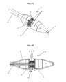
- FIG. 1is perspective view of one embodiment of a lumen reduction device
- FIG. 2Ais a perspective view of an end effector of the device of FIG. 1 ;
- FIG. 2Bis a cross-sectional view of the end effector of FIG. 2A taken across line A-A, showing the proximal and distal housing portions and the trough of the end effector;
- FIG. 2Cis a perspective view of one embodiment of a fastener for use with the lumen reduction device of FIGS. 1-2B ;
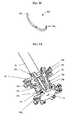
- FIG. 3Ais a perspective view of the actuators and fastener-retaining members of the end effector of FIG. 2B having a plurality of fasteners retained therein;
- FIG. 3Bis a front view of one of the fastener-retaining members of FIG. 3A ;
- FIG. 3Cis a transparent perspective view of the actuators and fastener-retaining members of the end effector of FIG. 2B ;
- FIG. 4is a partially cross-sectional view of the end effector of FIG. 1 having sutures coupled to fasteners contained therein;
- FIG. 5Ais a partially cut-away side view of the end effector of FIG. 1 positioned within a stoma and suctioning tissue into a trough formed in the end effector;
- FIG. 5Bis a partially cut-away side view of the end effector and stoma of FIG. 5A showing release of the fasteners from the fastener-retaining members;
- FIG. 5Cis a partially cut-away side view of the stoma of FIG. 5B following removal of the end effector of FIG. 2A , and showing sutures extending through the fasteners for cinching tissue around the stoma.
- the present inventionprovides devices and methods for reducing a size of a lumen.
- the devicecan include an end effector having a trough formed therein for receiving tissue, and for delivering a plurality of fasteners to the tissue.
- the fastenerscan be coupled by one or more sutures which can be used to cinch the tissue and thereby reduce the size of the lumen.
- the devicecan also include features to facilitate engagement of tissue within the trough, injury of tissue to promote healing, and various other features to facilitate use of the device.
- the present devicecan be used in any procedure where it is necessary to apply fasteners and/or reduce the size of a lumen, such as stoma, jejunum, duodenum, or colon reduction procedures.
- FIG. 1illustrates one exemplary embodiment of a lumen reduction device 10 for reducing the size of a lumen.
- the device 10includes an outer shaft 12 having proximal and distal ends 12 a , 12 b .
- the outer shaft 12can have virtually any configuration, and it can be flexible or rigid.
- the outer shaft 12has a configuration that allows it to be endoscopically inserted through the esophagus.
- the proximal end 12 acan include a handle 14 and the distal end 12 b can include an end effector 16 for receiving and treating tissue.
- the end effector 16is shown in more detail in FIGS. 2A-2B . While the shape of the end effector can vary, it is preferably shaped to be positioned within a lumen, and includes a trough for holding tissue. The end effector 16 is also preferably adapted to releasably retain one or more fasteners for delivering the fasteners to tissue disposed within the trough. In the illustrated embodiment, the end effector 16 includes proximal and distal housing portions 17 , 19 that are connected by a connector portion 18 , and that define the trough 20 therebetween. The housing portions 17 , 19 can be integrally formed with one another and/or the outer shaft 12 , or they can be separate from one another and/or the outer shaft 12 .
- each housing portion 17 , 19can have a variety of configurations, in the embodiment shown in FIG. 2B each housing portion 17 , 19 has a substantially cylindrical, hollow configuration for retaining one or more fasteners therein, as will be discussed in more detail below.
- the connector portion 18can have a diameter smaller than a diameter of the proximal and distal housing portions 17 , 19 to define the trough 20 therebetween.
- the housing portions 17 , 19can also include features to facilitate insertion into the esophagus.
- the distal housing portion 19can include a tapered end with a blunt tip.
- the proximal and distal housing portions 17 , 19can also optionally include a lumen 22 formed therethrough for receiving a guidewire to facilitate positioning of the device within a lumen.
- the trough 20 formed between the proximal and distal housing portions 17 , 19can be located at a variety of locations on the end effector 16 , and it can extend partially or entirely around a circumference thereof.
- the trough 20is formed around the entire circumference of the end effector 16 to allow tissue surrounding a lumen to be received therein.
- the trough 20can have any shape and size depending upon the amount of tissue to be received.
- the trough 20has a substantially rectangular cross-sectional shape with a backwall 21 that is defined by the connector 18 , and opposed endwalls 23 , 25 that are defined by the proximal and distal housing portions 17 , 19 .
- the size of the trough 20should be sufficient to receive the amount of tissue to be fastened.
- the trough 20has a depth d of at least about 3 mm and a width w of at least about 5 mm.
- the trough 20can also optionally have an adjustable size.
- one or both of the proximal and distal housing portions 17 , 19can be movably coupled to the connector 18 to allow the housing portions 17 , 19 to slide relative to one another and thereby increase or decrease the width w of the trough 20 .
- a lever located on the connector 18can optionally be provided for controlling and adjusting the size of the trough.
- the trough 20is configured to receive tissue. While a variety of techniques can be used to position tissue within the trough 20 , in one embodiment the trough 20 can include a plurality of suction elements 24 for suctioning tissue therein.
- the trough 20can include any number of suction elements 24 , and each suction element 24 can have any shape, such as ports or slots, and can have any size.
- the suction elements 24can also be formed anywhere on the trough 20 .
- the trough 20includes suction ports 24 that are located around the entire circumference of the trough 20 , that is, on the basewall 21 and the endwalls 23 , 25 .
- the suction ports 24can also be positioned in any pattern that is effective for engaging tissue, such as in equally spaced rows within the trough 20 .
- a suction forcecan be generated using a pump or other element coupled to the proximal end of the shaft or the handle to pull air into the ports and suction the tissue therein.
- the trough 20can also optionally be adapted to injure or cause intentional injury to tissue, thereby promoting healing when the tissue is cinched together.
- Any tissue-injuring techniquecan be used, and one or more tissue-injuring elements can be positioned anywhere within the trough 20 .
- one or more tissue-injuring elementsare positioned on the opposed endwalls 23 , 25 of the trough 20 .
- the tissue-injuring elementscan also be located around the entire circumference of the trough 20 and spaced a distance apart from one another or located only in zones that are being cinched.
- the tissue-injuring elementscan be in the form of electrical elements, such as electrodes for delivering RF, monopolar, bipolar, or other energy to the tissue, or mechanical elements, such as scrapers or little blades located on the endwalls of the trough that move to cut the tissue.
- the tissue-injuring elementsare in the form of two bipolar or monopolar strips that are disposed on the opposed endwalls 23 , 25 and around the circumference of the trough 20 .
- a portion of each endwall 23 , 25can be formed from a conductive material for receiving energy.
- tissue-injuring elements on the endwalls 23 , 25allows the applied energy to travel across or between the walls of the proximal and distal housing portions 17 , 19 and through tissue 64 contained within the trough 20 .
- Energycan be delivered to the strips through one or more leads extending through the housing and coupled to an internal or external energy source.
- the end effectorcan be adapted to hold one or more fasteners for delivering the fasteners to tissue disposed within the trough.
- the trough 20can include one or more channels 26 formed therein for seating the fasteners.
- the number and location of the channels 26can vary depending upon the desired amount of tissue to be cinched.
- the channels 26are disposed around the entire circumference of the trough 20 such that the fasteners are located in a circumferential pattern therearound.
- the shape and size of the channelscan also vary depending upon the type of fasteners used, and various fasteners known in the art can be used.
- the fasteners 28 dcan have an elongate configuration with opposed ends 28 d 1 , 28 d 2 that are adapted to penetrate tissue as shown in FIG. 2C , and the channels 26 have an elongate longitudinal configuration that extends through the sidewalls of the proximal and distal housing portions 17 , 19 , as well as the connector 18 .
- the fastenerscan be disposed within the channels 26 such that the fasteners extend across the channel 26 , as will be discussed in more detail below.
- the fastenersare biased to a closed, ring-shaped configuration, and the ends can be expanded to have an elongate configuration in an open position.
- the opposed ends of the fastenerscan be held within the channels 26 in an open configuration using one or more fastener-retaining members, as will be discussed below. Upon release from the channels 26 , the fasteners can close to form a ring-shaped member that engages the tissue.
- the fastenerscan also include features to facilitate penetration of tissue, such as pointed ends and/or lubrication.
- FIG. 2Cillustrates fastener 28 d having pointed end 28 d 2 .
- the size of each fastenercan also vary depending upon the type and amount of tissue to be cinched. In an exemplary embodiment, the fasteners have a diameter that is about 3.5 mm in a closed position.
- the fastenerscan be formed from a variety of biocompatible and superelastic materials, including, by way of non-limiting example, shape memory metals such as Nitinol.
- FIG. 3Billustrates fastener-retaining member 30 , which includes a central disc with several hook-shaped legs 34 a , 34 b , 34 c , 34 d , 34 e , 34 f , 34 g , 34 h (hereinafter 34 a - h ) extending outwardly therefrom for holding the ends of the fasteners.
- fastener-retaining member 30which includes a central disc with several hook-shaped legs 34 a , 34 b , 34 c , 34 d , 34 e , 34 f , 34 g , 34 h (hereinafter 34 a - h ) extending outwardly therefrom for holding the ends of the fasteners.
- the hook-shaped legs on the proximal fastener-retaining member 30are adapted to hold the first end of the fastener (first end 28 d 1 of fastener 28 d is shown) within the channels in the proximal housing portion 17
- the hook-shaped legs on the distal fastener-retaining member 32are adapted to hold the second, opposed end of the fasteners (second end 28 d 2 of fastener 28 d is shown) within the channels in the distal housing portion 19
- the hook-shaped legs 34 a - h on each fastener-retaining memberare preferably bent in the same direction and have substantially the same length to effect the simultaneous release of the legs of the fasteners, as will be discussed below. In other embodiments, as discussed above, each of the hook-shaped legs on each fastener-retaining member can have a different length to release the legs of the fasteners sequentially.
- the fastener-retaining members 30 , 32can be rotated to move the hook-shaped legs 34 a - h out of the channels, and thereby release the fasteners from the channels and into the tissue disposed in the trough. While a variety of techniques can be used to rotate the fastener-retaining members, in an exemplary embodiment, a first actuator 38 extends through the outer shaft 12 and is coupled to a midportion of the proximal fastener-retaining member 30 , and a second actuator 40 extends through the first actuator 38 and the connector 18 and is coupled to a mid-portion of the distal fastener-retaining member 32 .
- a proximal end of each actuator 38 , 40can include a lever 42 , 44 formed thereon and slidably disposed within a slot formed in the handle 14 .
- the levers 42 , 44can be rotated within the slots in the handle 14 to rotate the first and second actuators 38 , 40 simultaneously or independently of one another, thereby releasing the ends of the fasteners from the hook-shaped members, and allowing the fasteners to penetrate through and close around tissue disposed within the trough.
- rotation of the first and second actuatorscan cause the shortest leg of the fastener-retaining members to release the ends of the fastener held therein.
- the levers 42 , 44can optionally be biased, e.g. using a spring, to a first position to retain the ends of the fastener-retaining members within the channels, thereby retaining the ends of the fasteners in the channels and preventing accidental release of the fasteners.
- the handlecan include a locking mechanism for locking the levers in a first position.
- a dial, knob or any other mechanismcan be used to trigger rotation of the first and second actuators. While rotatable actuation is shown, a person skilled in the art will also appreciate that a variety of other techniques can be used to effect movement of the fastener-retaining members 30 , 32 , and thereby release the ends of the fasteners.
- the devicecan also be configured to hold one or more sutures to cinch the tissue engaged by the fasteners.
- FIG. 4illustrates suture 45 a , coupled to fasteners 28 a , 28 b , and suture 45 b coupled to fasteners 28 c , 28 d .
- the sutures 45 a , 45 bextend across the fasteners 28 a , 28 b , 28 c , 28 d along the outside of the first actuator 38 and up through the outer shaft (not shown).
- the suturescan extend through the actuators or they can be positioned external to the device.
- the number of suturescan vary depending upon the amount of tissue to be cinched, and the sutures can be coupled to any number of fasteners.
- the suturescan also be located in predetermined zones, such that only a certain portion of the tissue surrounding a lumen is cinched. In use, when the fasteners are engaged with the tissue, the suture will extend through the ring-shaped fasteners, and the sutures can be pulled and tied to cinch the tissue.
- FIGS. 5A-5Cillustrate one embodiment of an exemplary method for reducing a size of a lumen, such as a stoma, using, by way of non-limiting example, the device of FIGS. 1-4 .
- the devicecan be inserted down the esophagus.
- a scopecan optionally be used to facilitate positioning of the end effector.
- the stomachcan be insufflated to prevent collapse thereof and to allow for visibility of the stomach and stoma 64 .
- the trough 20can then be directed towards and positioned at the stoma 64 .
- suctioncan be applied to the tissue 64 using the suction ports to cause the tissue 64 to be suctioned into the trough 20 , as shown in FIG. 5A , and the tissue-injuring elements can be activated to cause injury to the tissue 64 within the trough 20 .
- a device adapted to injure the tissuecan be positioned at the tissue prior to the application of fasteners thereto from the end effector.
- argon plasma coagulationcan be used to injure the tissue, and a catheter having a controlled argon source and a high frequency electrical generator can be positioned at the tissue. The generator can then be activated, using an external energy source for example, such that current is delivered to the tissue and the tissue is injured.
- the fastenerscan be applied thereto.
- the first actuator located within the proximal housing portion 17is actuated by rotating the lever on the handle (shown in FIG. 1 ) to cause the proximal fastener-retaining member to rotate.
- the first end of the fastenersfirst end 28 d 1 of fastener 28 d is shown
- the second actuator located within the distal housing portion 19can then be actuated independently of the first actuator to rotate the distal fastener-retaining member. This can be achieved using the lever on the handle (shown in FIG. 1 ).
- the second end of the fasteners(second end 28 d 2 of fastener 28 d is shown) are simultaneously released from the channels.
- the endswill curve towards the first ends to form a ring-shaped fastener in the closed position.
- the first and second actuatorscan optionally be actuated at the same time, causing both ends of the fasteners to be simultaneously released into tissue, and/or the fastener-retaining members can be adapted such that actuation of the actuators causes the release of a single fastener into tissue.
- the stomachcan optionally be insufflated again if necessary to separate the fasteners from the device to effect removal thereof.
- the devicecan be removed, leaving the fasteners ( 28 d , 28 e are shown) with the sutures (suture 45 a is shown) extending therefrom, as shown in FIG. 5C .
- the trailing ends of each suturecan be tensioned to pull the fasteners together, thereby causing the tissue to cinch to reduce the diameter of the stoma.
- the suturescan be tied or a fastening device, such as a knotting member, can be used to secure the ends of the sutures to one another. The free ends can then be cut off, or the knotting member can include a cutting element to cut the suture ends off.
- Lumen reduction devicescan be designed to be disposed after a single use, or can be designed to be used multiple times. In either case, however, the device can be reconditioned for reuse after at least one use. Reconditioning can include any combination of the steps of disassembly of the device, followed by cleaning or replacement of particular pieces, and subsequent reassembly.
- the lumen reduction device of FIGS. 1-4can be reconditioned after the device has been used in a medical procedure.
- the devicecan be disassembled, and any number of the particular pieces (e.g., the fasteners, actuators, end effector, tissue-injury elements, and sutures) can be selectively replaced or removed in any combination.
- the fasteners and suturescan be replaced by adding a new fastener cartridge to the end effector or by replacing the proximal and distal fastener-retaining members with fully loaded fastener-retaining members and/or actuators.
- the devicecan be reassembled for subsequent use either at a reconditioning facility, or by a surgical team immediately prior to a surgical procedure.
- reconditioning of a lumen reduction devicecan utilize a variety of techniques for disassembly, cleaning/replacement, and reassembly. Use of such techniques, and the resulting reconditioned lumen reduction device, are all within the scope of the present application.
Landscapes
- Health & Medical Sciences (AREA)
- Life Sciences & Earth Sciences (AREA)
- Surgery (AREA)
- Heart & Thoracic Surgery (AREA)
- Engineering & Computer Science (AREA)
- Biomedical Technology (AREA)
- Nuclear Medicine, Radiotherapy & Molecular Imaging (AREA)
- Medical Informatics (AREA)
- Molecular Biology (AREA)
- Animal Behavior & Ethology (AREA)
- General Health & Medical Sciences (AREA)
- Public Health (AREA)
- Veterinary Medicine (AREA)
- Surgical Instruments (AREA)
- Media Introduction/Drainage Providing Device (AREA)
Abstract
Description
Claims (26)
Priority Applications (10)
| Application Number | Priority Date | Filing Date | Title |
|---|---|---|---|
| US11/307,698US8221438B2 (en) | 2006-02-17 | 2006-02-17 | Lumen reduction methods and devices |
| AU2007200283AAU2007200283B2 (en) | 2006-02-17 | 2007-01-24 | Lumen reduction methods and devices |
| CA2576324ACA2576324C (en) | 2006-02-17 | 2007-01-26 | Lumen reduction methods and devices |
| JP2007036796AJP4926747B2 (en) | 2006-02-17 | 2007-02-16 | Method and apparatus for reducing a lumen |
| EP07250668AEP1820454B1 (en) | 2006-02-17 | 2007-02-16 | Methods and devices for lumen reduction |
| MX2007002010AMX2007002010A (en) | 2006-02-17 | 2007-02-16 | Lumen reduction methods and devices. |
| AT07250668TATE438343T1 (en) | 2006-02-17 | 2007-02-16 | METHOD AND DEVICES FOR LUMEN REDUCTION |
| DE602007001812TDE602007001812D1 (en) | 2006-02-17 | 2007-02-16 | Methods and apparatus for reducing lumens |
| BRPI0700426ABRPI0700426B8 (en) | 2006-02-17 | 2007-02-21 | device to reduce the size of a lumen |
| HK07112937.4AHK1106992B (en) | 2006-02-17 | 2007-11-27 | Methods and devices for lumen reduction |
Applications Claiming Priority (1)
| Application Number | Priority Date | Filing Date | Title |
|---|---|---|---|
| US11/307,698US8221438B2 (en) | 2006-02-17 | 2006-02-17 | Lumen reduction methods and devices |
Publications (2)
| Publication Number | Publication Date |
|---|---|
| US20070198034A1 US20070198034A1 (en) | 2007-08-23 |
| US8221438B2true US8221438B2 (en) | 2012-07-17 |
Family
ID=38042783
Family Applications (1)
| Application Number | Title | Priority Date | Filing Date |
|---|---|---|---|
| US11/307,698Expired - Fee RelatedUS8221438B2 (en) | 2006-02-17 | 2006-02-17 | Lumen reduction methods and devices |
Country Status (9)
| Country | Link |
|---|---|
| US (1) | US8221438B2 (en) |
| EP (1) | EP1820454B1 (en) |
| JP (1) | JP4926747B2 (en) |
| AT (1) | ATE438343T1 (en) |
| AU (1) | AU2007200283B2 (en) |
| BR (1) | BRPI0700426B8 (en) |
| CA (1) | CA2576324C (en) |
| DE (1) | DE602007001812D1 (en) |
| MX (1) | MX2007002010A (en) |
Cited By (2)
| Publication number | Priority date | Publication date | Assignee | Title |
|---|---|---|---|---|
| US20190150928A1 (en)* | 2014-08-24 | 2019-05-23 | Alon Boiman | Anastomosis suturing device |
| US20230210523A1 (en)* | 2020-09-10 | 2023-07-06 | Edwards Lifesciences Corporation | Closing tissue openings |
Families Citing this family (11)
| Publication number | Priority date | Publication date | Assignee | Title |
|---|---|---|---|---|
| US7445010B2 (en)* | 2003-01-29 | 2008-11-04 | Torax Medical, Inc. | Use of magnetic implants to treat issue structures |
| JP2011517977A (en) | 2008-04-08 | 2011-06-23 | エンドプロ ソリューションズ エル.エル.シー. | Device and method for reducing stomach |
| US20100023026A1 (en)* | 2008-07-25 | 2010-01-28 | Zeiner Mark S | Reloadable laparoscopic fastener deploying device with disposable cartridge for use in a gastric volume reduction procedure |
| US20100023022A1 (en)* | 2008-07-25 | 2010-01-28 | Zeiner Mark S | Reloadable laparoscopic fastener deploying device with disposable cartridge use in a gastric volume reduction procedure |
| US20100023025A1 (en)* | 2008-07-25 | 2010-01-28 | Zeiner Mark S | Reloadable laparoscopic fastener deploying device with disposable cartridge for use in a gastric volume reduction procedure |
| US20100023024A1 (en)* | 2008-07-25 | 2010-01-28 | Zeiner Mark S | Reloadable laparoscopic fastener deploying device with disposable cartridge for use in a gastric volume reduction procedure |
| DE102009002768A1 (en)* | 2009-04-30 | 2010-11-04 | Celon Ag Medical Instruments | Material layer and electrosurgical system for electrosurgical tissue fusion |
| US8800842B2 (en) | 2010-09-17 | 2014-08-12 | Thomas E. Menzel | Internal gastric bander for obesity |
| US9545329B2 (en) | 2011-02-21 | 2017-01-17 | International Medical Technology | Flow control and collection device |
| US9498371B2 (en) | 2011-02-21 | 2016-11-22 | International Medical Technology, Inc. | Flow control and collection device |
| US10307165B2 (en) | 2015-09-24 | 2019-06-04 | Ethicon Llc | Apparatus and method for radially bunching a bodily lumen |
Citations (96)
| Publication number | Priority date | Publication date | Assignee | Title |
|---|---|---|---|---|
| US2004013A (en) | 1934-07-11 | 1935-06-04 | Clarence E Reed | Antifriction bearing assembly for drills |
| US2004014A (en) | 1931-08-05 | 1935-06-04 | Alfred F Sanford | Refrigerating apparatus |
| US2004172A (en) | 1934-07-31 | 1935-06-11 | Everett F Niday | Starting block |
| US4841888A (en) | 1984-09-11 | 1989-06-27 | Mills Timothy N | Sewing machine |
| US4899744A (en)* | 1988-12-15 | 1990-02-13 | Tatsuo Fujitsuka | Apparatus for anastomosing digestive tract |
| US5041129A (en) | 1990-07-02 | 1991-08-20 | Acufex Microsurgical, Inc. | Slotted suture anchor and method of anchoring a suture |
| US5080663A (en) | 1990-09-26 | 1992-01-14 | Univerity College London | Sewing device |
| US5217486A (en) | 1992-02-18 | 1993-06-08 | Mitek Surgical Products, Inc. | Suture anchor and installation tool |
| US5242457A (en)* | 1992-05-08 | 1993-09-07 | Ethicon, Inc. | Surgical instrument and staples for applying purse string sutures |
| US5269809A (en) | 1990-07-02 | 1993-12-14 | American Cyanamid Company | Locking mechanism for use with a slotted suture anchor |
| US5376101A (en) | 1992-10-09 | 1994-12-27 | The United States Surgical Corporation | Suture retaining clip |
| US5395030A (en)* | 1992-06-04 | 1995-03-07 | Olympus Optical Co., Ltd. | Surgical device for stapling and fastening body tissues |
| EP0641546A1 (en) | 1993-09-03 | 1995-03-08 | Ethicon, Inc. | Endoscopic surgical instrument and staples for applying purse string sutures |
| US5398670A (en) | 1993-08-31 | 1995-03-21 | Ethicon, Inc. | Lumen traversing device |
| US5437681A (en) | 1994-01-13 | 1995-08-01 | Suturtek Inc. | Suturing instrument with thread management |
| US5462558A (en) | 1994-08-29 | 1995-10-31 | United States Surgical Corporation | Suture clip applier |
| US5507754A (en)* | 1993-08-20 | 1996-04-16 | United States Surgical Corporation | Apparatus and method for applying and adjusting an anchoring device |
| US5514159A (en) | 1994-09-13 | 1996-05-07 | United States Surgical Corporation | Guillotine suture clip |
| US5540705A (en) | 1995-05-19 | 1996-07-30 | Suturtek, Inc. | Suturing instrument with thread management |
| US5571119A (en) | 1993-10-25 | 1996-11-05 | Children's Medical Center Corporation | Retractable suture needle with self-contained driver |
| US5584861A (en) | 1992-09-04 | 1996-12-17 | University College London | Device for use in securing a thread |
| US5707380A (en)* | 1996-07-23 | 1998-01-13 | United States Surgical Corporation | Anastomosis instrument and method |
| US5709693A (en) | 1996-02-20 | 1998-01-20 | Cardiothoracic System, Inc. | Stitcher |
| US5713910A (en) | 1992-09-04 | 1998-02-03 | Laurus Medical Corporation | Needle guidance system for endoscopic suture device |
| US5755730A (en) | 1994-03-23 | 1998-05-26 | University College London | Device for use in cutting threads |
| US5807393A (en)* | 1992-12-22 | 1998-09-15 | Ethicon Endo-Surgery, Inc. | Surgical tissue treating device with locking mechanism |
| US5814071A (en) | 1994-11-10 | 1998-09-29 | Innovasive Devices, Inc. | Suture anchor assembly and methods |
| US5860992A (en) | 1996-01-31 | 1999-01-19 | Heartport, Inc. | Endoscopic suturing devices and methods |
| US5887594A (en) | 1997-09-22 | 1999-03-30 | Beth Israel Deaconess Medical Center Inc. | Methods and devices for gastroesophageal reflux reduction |
| US5899921A (en) | 1997-07-25 | 1999-05-04 | Innovasive Devices, Inc. | Connector device and method for surgically joining and securing flexible tissue repair members |
| US6010515A (en) | 1993-09-03 | 2000-01-04 | University College London | Device for use in tying knots |
| US6036694A (en) | 1998-08-03 | 2000-03-14 | Innovasive Devices, Inc. | Self-tensioning soft tissue fixation device and method |
| US6193734B1 (en) | 1998-01-23 | 2001-02-27 | Heartport, Inc. | System for performing vascular anastomoses |
| US6200329B1 (en) | 1998-08-31 | 2001-03-13 | Smith & Nephew, Inc. | Suture collet |
| US6254642B1 (en) | 1997-12-09 | 2001-07-03 | Thomas V. Taylor | Perorally insertable gastroesophageal anti-reflux valve prosthesis and tool for implantation thereof |
| US20010023352A1 (en) | 1992-09-04 | 2001-09-20 | Gordon Norman S. | Suturing instruments and methods of use |
| US6346111B1 (en) | 1992-09-04 | 2002-02-12 | Scimed Life Systems, Inc. | Suturing instruments and methods of use |
| US20020107530A1 (en) | 2001-02-02 | 2002-08-08 | Sauer Jude S. | System for endoscopic suturing |
| US6443962B1 (en) | 1997-09-11 | 2002-09-03 | Benny Gaber | Stitching tool |
| US6454778B2 (en) | 1998-03-20 | 2002-09-24 | Scimed Life Systems, Inc. | Endoscopic suture systems |
| US6494888B1 (en) | 1999-06-22 | 2002-12-17 | Ndo Surgical, Inc. | Tissue reconfiguration |
| US20020193809A1 (en) | 2001-06-14 | 2002-12-19 | Meade John C. | Apparatus and method for surgical suturing with thread management |
| US6500195B2 (en) | 1993-05-14 | 2002-12-31 | Peter M. Bonutti | Method and apparatus for anchoring a suture |
| US6506196B1 (en) | 1999-06-22 | 2003-01-14 | Ndo Surgical, Inc. | Device and method for correction of a painful body defect |
| US20030032967A1 (en) | 2001-06-20 | 2003-02-13 | Park Medical, Llc | Anastomotic device |
| US6524328B2 (en) | 2001-04-12 | 2003-02-25 | Scion International, Inc. | Suture lock, lock applicator and method therefor |
| US6540789B1 (en) | 2000-06-15 | 2003-04-01 | Scimed Life Systems, Inc. | Method for treating morbid obesity |
| US20030083674A1 (en) | 2001-10-04 | 2003-05-01 | Gibbens George H. | Cycling suturing and knot-tying device |
| US6558400B2 (en) | 2001-05-30 | 2003-05-06 | Satiety, Inc. | Obesity treatment tools and methods |
| US6572629B2 (en) | 2000-08-17 | 2003-06-03 | Johns Hopkins University | Gastric reduction endoscopy |
| US20030109900A1 (en) | 2000-09-15 | 2003-06-12 | Jonathan Martinek | Knotless tissue anchor |
| US20030120292A1 (en) | 2001-06-20 | 2003-06-26 | Park Medical, Llc | Anastomotic device |
| US20030171760A1 (en) | 2000-05-19 | 2003-09-11 | Gambale Richard A | Tissue capturing and suturing device and method |
| US20030181924A1 (en) | 2002-01-30 | 2003-09-25 | Olympus Optical Co., Ltd. | Endoscopic suturing system |
| US20030225312A1 (en) | 2002-03-18 | 2003-12-04 | Anthony Kalloo | Endoscopic system for treating inside of body cavity |
| US20030229296A1 (en) | 2002-03-18 | 2003-12-11 | Olympus Optical Co., Ltd. | Guide tube |
| US6663639B1 (en) | 1999-06-22 | 2003-12-16 | Ndo Surgical, Inc. | Methods and devices for tissue reconfiguration |
| US20030233108A1 (en) | 2002-06-12 | 2003-12-18 | Scimed Life Systems, Inc. | Endoscopic suture instrument |
| US20040006351A1 (en) | 2002-07-02 | 2004-01-08 | Jamy Gannoe | Method and device for use in tissue approximation and fixation |
| US20040034369A1 (en) | 2001-02-02 | 2004-02-19 | Sauer Jude S. | System for endoscopic suturing |
| WO2004021894A1 (en) | 2002-09-09 | 2004-03-18 | Brian Kelleher | Device and method for endoluminal therapy |
| US6719763B2 (en) | 2000-09-29 | 2004-04-13 | Olympus Optical Co., Ltd. | Endoscopic suturing device |
| US20040082963A1 (en)* | 2002-10-23 | 2004-04-29 | Jamy Gannoe | Method and device for use in endoscopic organ procedures |
| US20040098050A1 (en) | 2002-11-19 | 2004-05-20 | Opus Medical, Inc. | Devices and methods for repairing soft tissue |
| US6746460B2 (en) | 2002-08-07 | 2004-06-08 | Satiety, Inc. | Intra-gastric fastening devices |
| US20040122456A1 (en) | 2002-12-11 | 2004-06-24 | Saadat Vahid C. | Methods and apparatus for gastric reduction |
| US20040122473A1 (en) | 2002-12-11 | 2004-06-24 | Ewers Richard C. | Delivery systems and methods for gastric reduction |
| US6755843B2 (en) | 2000-09-29 | 2004-06-29 | Olympus Optical Co., Ltd. | Endoscopic suturing device |
| US20040147958A1 (en) | 2002-12-11 | 2004-07-29 | Usgi Medical | Apparatus and methods for forming and securing gastrointestinal tissue folds |
| US20040162568A1 (en) | 1999-06-25 | 2004-08-19 | Usgi Medical | Apparatus and methods for forming and securing gastrointestinal tissue folds |
| US20040194790A1 (en) | 1999-06-22 | 2004-10-07 | Ndo Surgical, Inc. | Tissue reconfiguration |
| US20040210243A1 (en) | 2003-04-16 | 2004-10-21 | Jamy Gannoe | Method and devices for modifying the function of a body organ |
| US20040215058A1 (en) | 2002-09-06 | 2004-10-28 | Zirps Christopher T | Endoscopic accessory mounting adaptor |
| US6821858B2 (en) | 2000-05-01 | 2004-11-23 | Seiko Epson Corporation | Semiconductor devices and methods for manufacturing the same |
| US6835200B2 (en) | 1999-06-22 | 2004-12-28 | Ndo Surgical. Inc. | Method and devices for tissue reconfiguration |
| US20050015101A1 (en) | 2001-10-04 | 2005-01-20 | Gibbens George H. | Leverage locking reversible cyclic suturing and knot-tying device |
| US20050033319A1 (en) | 2003-05-16 | 2005-02-10 | Gambale Richard A. | Single intubation, multi-stitch endoscopic suturing system |
| US6869395B2 (en) | 2000-05-15 | 2005-03-22 | C. R. Bard, Inc. | Endoscopic accessory attachment mechanism |
| US20050070934A1 (en) | 2003-09-30 | 2005-03-31 | Tanaka Don A. | Anastomosis wire ring device |
| US20050070926A1 (en) | 2003-09-30 | 2005-03-31 | Ortiz Mark S. | Applier for fastener for single lumen access anastomosis |
| US20050070921A1 (en) | 2003-09-30 | 2005-03-31 | Ortiz Mark S. | Single lumen anastomosis applier for self-deploying fastener |
| US20050070935A1 (en) | 2003-09-30 | 2005-03-31 | Ortiz Mark S. | Single lumen access deployable ring for intralumenal anastomosis |
| US20050070931A1 (en) | 2003-08-06 | 2005-03-31 | Rhodemann Li | Method and apparatus for creating a restriction in the stomach or other anatomical structure |
| US20050075654A1 (en) | 2003-10-06 | 2005-04-07 | Brian Kelleher | Methods and devices for soft tissue securement |
| US20050119542A1 (en) | 2002-02-27 | 2005-06-02 | Stoddart Hugh F. | Method and apparatus for determining cerebral oxygen saturation |
| US6908427B2 (en) | 2002-12-30 | 2005-06-21 | PARÉ Surgical, Inc. | Flexible endoscope capsule |
| US20050143760A1 (en) | 2001-05-01 | 2005-06-30 | Imran Mir A. | Endoscopic gastric constriction device |
| US20050143762A1 (en) | 2003-09-15 | 2005-06-30 | Paraschac Joseph F. | Suture locking device and methods |
| US20050149067A1 (en) | 2002-01-30 | 2005-07-07 | Olympus Corporation | Endoscopic suturing system |
| US20050192601A1 (en) | 2004-02-27 | 2005-09-01 | Demarais Denise M. | Methods and devices for reducing hollow organ volume |
| US20050192599A1 (en) | 2004-02-13 | 2005-09-01 | Demarais Denise M. | Methods for reducing hollow organ volume |
| US20050203488A1 (en) | 2004-03-09 | 2005-09-15 | Usgi Medical Inc. | Apparatus and methods for mapping out endoluminal gastrointestinal surgery |
| US20050228415A1 (en) | 2004-03-23 | 2005-10-13 | Michael Gertner | Methods and devices for percutaneous, non-laparoscopic treatment of obesity |
| US20050273138A1 (en)* | 2003-12-19 | 2005-12-08 | Guided Delivery Systems, Inc. | Devices and methods for anchoring tissue |
| US20060020277A1 (en) | 2004-07-20 | 2006-01-26 | Gostout Christopher J | Gastric reshaping devices and methods |
| US7588582B2 (en)* | 2002-06-13 | 2009-09-15 | Guided Delivery Systems Inc. | Methods for remodeling cardiac tissue |
Family Cites Families (6)
| Publication number | Priority date | Publication date | Assignee | Title |
|---|---|---|---|---|
| US7223273B2 (en)* | 1996-07-23 | 2007-05-29 | Tyco Healthcare Group Lp | Anastomosis instrument and method for performing same |
| US7083629B2 (en)* | 2001-05-30 | 2006-08-01 | Satiety, Inc. | Overtube apparatus for insertion into a body |
| AU2003230359B2 (en)* | 2002-05-10 | 2008-11-13 | Covidien Lp | Electrosurgical stapling apparatus |
| JP4142369B2 (en)* | 2002-08-07 | 2008-09-03 | オリンパス株式会社 | Endoscopic treatment system |
| US20050080444A1 (en)* | 2003-10-14 | 2005-04-14 | Kraemer Stefan J.M. | Transesophageal gastric reduction device, system and method |
| JP4257270B2 (en)* | 2004-07-14 | 2009-04-22 | オリンパス株式会社 | Biological tissue suturing method and biological tissue suturing device |
- 2006
- 2006-02-17USUS11/307,698patent/US8221438B2/ennot_activeExpired - Fee Related
- 2007
- 2007-01-24AUAU2007200283Apatent/AU2007200283B2/ennot_activeCeased
- 2007-01-26CACA2576324Apatent/CA2576324C/ennot_activeExpired - Fee Related
- 2007-02-16EPEP07250668Apatent/EP1820454B1/ennot_activeNot-in-force
- 2007-02-16MXMX2007002010Apatent/MX2007002010A/enactiveIP Right Grant
- 2007-02-16JPJP2007036796Apatent/JP4926747B2/ennot_activeExpired - Fee Related
- 2007-02-16ATAT07250668Tpatent/ATE438343T1/ennot_activeIP Right Cessation
- 2007-02-16DEDE602007001812Tpatent/DE602007001812D1/enactiveActive
- 2007-02-21BRBRPI0700426Apatent/BRPI0700426B8/ennot_activeIP Right Cessation
Patent Citations (113)
| Publication number | Priority date | Publication date | Assignee | Title |
|---|---|---|---|---|
| US2004014A (en) | 1931-08-05 | 1935-06-04 | Alfred F Sanford | Refrigerating apparatus |
| US2004013A (en) | 1934-07-11 | 1935-06-04 | Clarence E Reed | Antifriction bearing assembly for drills |
| US2004172A (en) | 1934-07-31 | 1935-06-11 | Everett F Niday | Starting block |
| US4841888A (en) | 1984-09-11 | 1989-06-27 | Mills Timothy N | Sewing machine |
| US4899744A (en)* | 1988-12-15 | 1990-02-13 | Tatsuo Fujitsuka | Apparatus for anastomosing digestive tract |
| US5041129A (en) | 1990-07-02 | 1991-08-20 | Acufex Microsurgical, Inc. | Slotted suture anchor and method of anchoring a suture |
| US5269809A (en) | 1990-07-02 | 1993-12-14 | American Cyanamid Company | Locking mechanism for use with a slotted suture anchor |
| US5080663A (en) | 1990-09-26 | 1992-01-14 | Univerity College London | Sewing device |
| US5217486A (en) | 1992-02-18 | 1993-06-08 | Mitek Surgical Products, Inc. | Suture anchor and installation tool |
| US5242457A (en)* | 1992-05-08 | 1993-09-07 | Ethicon, Inc. | Surgical instrument and staples for applying purse string sutures |
| US5395030A (en)* | 1992-06-04 | 1995-03-07 | Olympus Optical Co., Ltd. | Surgical device for stapling and fastening body tissues |
| US6358259B1 (en) | 1992-09-04 | 2002-03-19 | University College London | Device for use in tying knots |
| US20040059350A1 (en) | 1992-09-04 | 2004-03-25 | Scimed Life Systems, Inc. | Suturing instruments and methods of use |
| US6346111B1 (en) | 1992-09-04 | 2002-02-12 | Scimed Life Systems, Inc. | Suturing instruments and methods of use |
| US5584861A (en) | 1992-09-04 | 1996-12-17 | University College London | Device for use in securing a thread |
| US20010023352A1 (en) | 1992-09-04 | 2001-09-20 | Gordon Norman S. | Suturing instruments and methods of use |
| US5713910A (en) | 1992-09-04 | 1998-02-03 | Laurus Medical Corporation | Needle guidance system for endoscopic suture device |
| US5376101A (en) | 1992-10-09 | 1994-12-27 | The United States Surgical Corporation | Suture retaining clip |
| US5807393A (en)* | 1992-12-22 | 1998-09-15 | Ethicon Endo-Surgery, Inc. | Surgical tissue treating device with locking mechanism |
| US6500195B2 (en) | 1993-05-14 | 2002-12-31 | Peter M. Bonutti | Method and apparatus for anchoring a suture |
| US5507754A (en)* | 1993-08-20 | 1996-04-16 | United States Surgical Corporation | Apparatus and method for applying and adjusting an anchoring device |
| US5398670A (en) | 1993-08-31 | 1995-03-21 | Ethicon, Inc. | Lumen traversing device |
| EP0641546A1 (en) | 1993-09-03 | 1995-03-08 | Ethicon, Inc. | Endoscopic surgical instrument and staples for applying purse string sutures |
| US6010515A (en) | 1993-09-03 | 2000-01-04 | University College London | Device for use in tying knots |
| US5571119A (en) | 1993-10-25 | 1996-11-05 | Children's Medical Center Corporation | Retractable suture needle with self-contained driver |
| US5437681A (en) | 1994-01-13 | 1995-08-01 | Suturtek Inc. | Suturing instrument with thread management |
| US5755730A (en) | 1994-03-23 | 1998-05-26 | University College London | Device for use in cutting threads |
| US5462558A (en) | 1994-08-29 | 1995-10-31 | United States Surgical Corporation | Suture clip applier |
| US5514159A (en) | 1994-09-13 | 1996-05-07 | United States Surgical Corporation | Guillotine suture clip |
| US5814071A (en) | 1994-11-10 | 1998-09-29 | Innovasive Devices, Inc. | Suture anchor assembly and methods |
| US5540705A (en) | 1995-05-19 | 1996-07-30 | Suturtek, Inc. | Suturing instrument with thread management |
| US5860992A (en) | 1996-01-31 | 1999-01-19 | Heartport, Inc. | Endoscopic suturing devices and methods |
| US5709693A (en) | 1996-02-20 | 1998-01-20 | Cardiothoracic System, Inc. | Stitcher |
| US5707380A (en)* | 1996-07-23 | 1998-01-13 | United States Surgical Corporation | Anastomosis instrument and method |
| US5902321A (en) | 1997-07-25 | 1999-05-11 | Innovasive Devices, Inc. | Device and method for delivering a connector for surgically joining and securing flexible tissue repair members |
| US5899921A (en) | 1997-07-25 | 1999-05-04 | Innovasive Devices, Inc. | Connector device and method for surgically joining and securing flexible tissue repair members |
| US6443962B1 (en) | 1997-09-11 | 2002-09-03 | Benny Gaber | Stitching tool |
| US5887594A (en) | 1997-09-22 | 1999-03-30 | Beth Israel Deaconess Medical Center Inc. | Methods and devices for gastroesophageal reflux reduction |
| US6254642B1 (en) | 1997-12-09 | 2001-07-03 | Thomas V. Taylor | Perorally insertable gastroesophageal anti-reflux valve prosthesis and tool for implantation thereof |
| US6193734B1 (en) | 1998-01-23 | 2001-02-27 | Heartport, Inc. | System for performing vascular anastomoses |
| US6454778B2 (en) | 1998-03-20 | 2002-09-24 | Scimed Life Systems, Inc. | Endoscopic suture systems |
| US20040002720A1 (en) | 1998-03-20 | 2004-01-01 | Scimed Life Systems, Inc. | Endoscopic suture systems |
| US6036694A (en) | 1998-08-03 | 2000-03-14 | Innovasive Devices, Inc. | Self-tensioning soft tissue fixation device and method |
| US6200329B1 (en) | 1998-08-31 | 2001-03-13 | Smith & Nephew, Inc. | Suture collet |
| US6835200B2 (en) | 1999-06-22 | 2004-12-28 | Ndo Surgical. Inc. | Method and devices for tissue reconfiguration |
| US20040193184A1 (en) | 1999-06-22 | 2004-09-30 | Ndo Surgical, Inc., A Massachusetts Corporation | Methods and devices for tissue reconfiguration |
| US20040194790A1 (en) | 1999-06-22 | 2004-10-07 | Ndo Surgical, Inc. | Tissue reconfiguration |
| US6506196B1 (en) | 1999-06-22 | 2003-01-14 | Ndo Surgical, Inc. | Device and method for correction of a painful body defect |
| US6773441B1 (en) | 1999-06-22 | 2004-08-10 | Ndo Surgical, Inc. | Methods and devices for tissue reconfiguration |
| EP1447052A2 (en) | 1999-06-22 | 2004-08-18 | NDO Surgical, Inc. | Gerd treatment apparatus and method |
| US6663639B1 (en) | 1999-06-22 | 2003-12-16 | Ndo Surgical, Inc. | Methods and devices for tissue reconfiguration |
| US6494888B1 (en) | 1999-06-22 | 2002-12-17 | Ndo Surgical, Inc. | Tissue reconfiguration |
| US20050075653A1 (en) | 1999-06-25 | 2005-04-07 | Usgi Medical Inc. | Apparatus and methods for forming and securing gastrointestinal tissue folds |
| US20040162568A1 (en) | 1999-06-25 | 2004-08-19 | Usgi Medical | Apparatus and methods for forming and securing gastrointestinal tissue folds |
| US6821858B2 (en) | 2000-05-01 | 2004-11-23 | Seiko Epson Corporation | Semiconductor devices and methods for manufacturing the same |
| US6869395B2 (en) | 2000-05-15 | 2005-03-22 | C. R. Bard, Inc. | Endoscopic accessory attachment mechanism |
| US20030171760A1 (en) | 2000-05-19 | 2003-09-11 | Gambale Richard A | Tissue capturing and suturing device and method |
| US6540789B1 (en) | 2000-06-15 | 2003-04-01 | Scimed Life Systems, Inc. | Method for treating morbid obesity |
| US6572629B2 (en) | 2000-08-17 | 2003-06-03 | Johns Hopkins University | Gastric reduction endoscopy |
| US20030109900A1 (en) | 2000-09-15 | 2003-06-12 | Jonathan Martinek | Knotless tissue anchor |
| US6719763B2 (en) | 2000-09-29 | 2004-04-13 | Olympus Optical Co., Ltd. | Endoscopic suturing device |
| US6755843B2 (en) | 2000-09-29 | 2004-06-29 | Olympus Optical Co., Ltd. | Endoscopic suturing device |
| US20050165419A1 (en) | 2001-02-02 | 2005-07-28 | Sauer Jude S. | System for endoscopic suturing |
| US20020107530A1 (en) | 2001-02-02 | 2002-08-08 | Sauer Jude S. | System for endoscopic suturing |
| US20040034369A1 (en) | 2001-02-02 | 2004-02-19 | Sauer Jude S. | System for endoscopic suturing |
| US6524328B2 (en) | 2001-04-12 | 2003-02-25 | Scion International, Inc. | Suture lock, lock applicator and method therefor |
| US20050143760A1 (en) | 2001-05-01 | 2005-06-30 | Imran Mir A. | Endoscopic gastric constriction device |
| US20040024386A1 (en) | 2001-05-30 | 2004-02-05 | Deem Mark E. | Obesity treatment tools and methods |
| US6558400B2 (en) | 2001-05-30 | 2003-05-06 | Satiety, Inc. | Obesity treatment tools and methods |
| US20030120265A1 (en) | 2001-05-30 | 2003-06-26 | Deem Mark E. | Obesity treatment tools and methods |
| US20040122453A1 (en) | 2001-05-30 | 2004-06-24 | Satiety, Inc. | Obesity treatment tools and methods |
| US20040122452A1 (en) | 2001-05-30 | 2004-06-24 | Satiety, Inc. | Obesity treatment tools and methods |
| US20020193809A1 (en) | 2001-06-14 | 2002-12-19 | Meade John C. | Apparatus and method for surgical suturing with thread management |
| US20030032967A1 (en) | 2001-06-20 | 2003-02-13 | Park Medical, Llc | Anastomotic device |
| US20030120292A1 (en) | 2001-06-20 | 2003-06-26 | Park Medical, Llc | Anastomotic device |
| US20030083674A1 (en) | 2001-10-04 | 2003-05-01 | Gibbens George H. | Cycling suturing and knot-tying device |
| US20050015101A1 (en) | 2001-10-04 | 2005-01-20 | Gibbens George H. | Leverage locking reversible cyclic suturing and knot-tying device |
| US20030181924A1 (en) | 2002-01-30 | 2003-09-25 | Olympus Optical Co., Ltd. | Endoscopic suturing system |
| US20050149067A1 (en) | 2002-01-30 | 2005-07-07 | Olympus Corporation | Endoscopic suturing system |
| US20050119542A1 (en) | 2002-02-27 | 2005-06-02 | Stoddart Hugh F. | Method and apparatus for determining cerebral oxygen saturation |
| US20030229296A1 (en) | 2002-03-18 | 2003-12-11 | Olympus Optical Co., Ltd. | Guide tube |
| US20030225312A1 (en) | 2002-03-18 | 2003-12-04 | Anthony Kalloo | Endoscopic system for treating inside of body cavity |
| US20030233108A1 (en) | 2002-06-12 | 2003-12-18 | Scimed Life Systems, Inc. | Endoscopic suture instrument |
| US6955643B2 (en) | 2002-06-12 | 2005-10-18 | Boston Scientific Scimed, Inc. | Endoscopic suture instrument |
| US20030233104A1 (en) | 2002-06-12 | 2003-12-18 | Scimed Life Systems, Inc. | Suturing instrument with deflectable head |
| US7588582B2 (en)* | 2002-06-13 | 2009-09-15 | Guided Delivery Systems Inc. | Methods for remodeling cardiac tissue |
| US20040006351A1 (en) | 2002-07-02 | 2004-01-08 | Jamy Gannoe | Method and device for use in tissue approximation and fixation |
| US6773440B2 (en) | 2002-07-02 | 2004-08-10 | Satiety, Inc. | Method and device for use in tissue approximation and fixation |
| US6746460B2 (en) | 2002-08-07 | 2004-06-08 | Satiety, Inc. | Intra-gastric fastening devices |
| US20040215058A1 (en) | 2002-09-06 | 2004-10-28 | Zirps Christopher T | Endoscopic accessory mounting adaptor |
| WO2004021894A1 (en) | 2002-09-09 | 2004-03-18 | Brian Kelleher | Device and method for endoluminal therapy |
| US20050055038A1 (en) | 2002-09-09 | 2005-03-10 | Brian Kelleher | Device and method for endoluminal therapy |
| US20040082963A1 (en)* | 2002-10-23 | 2004-04-29 | Jamy Gannoe | Method and device for use in endoscopic organ procedures |
| US20040098050A1 (en) | 2002-11-19 | 2004-05-20 | Opus Medical, Inc. | Devices and methods for repairing soft tissue |
| US20040122456A1 (en) | 2002-12-11 | 2004-06-24 | Saadat Vahid C. | Methods and apparatus for gastric reduction |
| US20040122473A1 (en) | 2002-12-11 | 2004-06-24 | Ewers Richard C. | Delivery systems and methods for gastric reduction |
| US20040147958A1 (en) | 2002-12-11 | 2004-07-29 | Usgi Medical | Apparatus and methods for forming and securing gastrointestinal tissue folds |
| US6908427B2 (en) | 2002-12-30 | 2005-06-21 | PARÉ Surgical, Inc. | Flexible endoscope capsule |
| US20040210243A1 (en) | 2003-04-16 | 2004-10-21 | Jamy Gannoe | Method and devices for modifying the function of a body organ |
| US20050033319A1 (en) | 2003-05-16 | 2005-02-10 | Gambale Richard A. | Single intubation, multi-stitch endoscopic suturing system |
| US20050070931A1 (en) | 2003-08-06 | 2005-03-31 | Rhodemann Li | Method and apparatus for creating a restriction in the stomach or other anatomical structure |
| US20050143762A1 (en) | 2003-09-15 | 2005-06-30 | Paraschac Joseph F. | Suture locking device and methods |
| US20050070935A1 (en) | 2003-09-30 | 2005-03-31 | Ortiz Mark S. | Single lumen access deployable ring for intralumenal anastomosis |
| US20050070921A1 (en) | 2003-09-30 | 2005-03-31 | Ortiz Mark S. | Single lumen anastomosis applier for self-deploying fastener |
| US20050070926A1 (en) | 2003-09-30 | 2005-03-31 | Ortiz Mark S. | Applier for fastener for single lumen access anastomosis |
| US20050070934A1 (en) | 2003-09-30 | 2005-03-31 | Tanaka Don A. | Anastomosis wire ring device |
| US20050075654A1 (en) | 2003-10-06 | 2005-04-07 | Brian Kelleher | Methods and devices for soft tissue securement |
| US20050273138A1 (en)* | 2003-12-19 | 2005-12-08 | Guided Delivery Systems, Inc. | Devices and methods for anchoring tissue |
| US20050192599A1 (en) | 2004-02-13 | 2005-09-01 | Demarais Denise M. | Methods for reducing hollow organ volume |
| US20050192601A1 (en) | 2004-02-27 | 2005-09-01 | Demarais Denise M. | Methods and devices for reducing hollow organ volume |
| US20050203488A1 (en) | 2004-03-09 | 2005-09-15 | Usgi Medical Inc. | Apparatus and methods for mapping out endoluminal gastrointestinal surgery |
| US20050228415A1 (en) | 2004-03-23 | 2005-10-13 | Michael Gertner | Methods and devices for percutaneous, non-laparoscopic treatment of obesity |
| US20060020277A1 (en) | 2004-07-20 | 2006-01-26 | Gostout Christopher J | Gastric reshaping devices and methods |
Non-Patent Citations (1)
| Title |
|---|
| Partial EP Search Report, Appl. No. 07250668.6, dated Jun. 5, 2007, 6 pp. |
Cited By (4)
| Publication number | Priority date | Publication date | Assignee | Title |
|---|---|---|---|---|
| US20190150928A1 (en)* | 2014-08-24 | 2019-05-23 | Alon Boiman | Anastomosis suturing device |
| US10695064B2 (en)* | 2014-08-24 | 2020-06-30 | Alon Boiman | Anastomosis suturing device |
| US20230210523A1 (en)* | 2020-09-10 | 2023-07-06 | Edwards Lifesciences Corporation | Closing tissue openings |
| US12369905B2 (en)* | 2020-09-10 | 2025-07-29 | Edwards Lifesciences Corporation | Closing tissue openings |
Also Published As
| Publication number | Publication date |
|---|---|
| BRPI0700426B1 (en) | 2018-08-28 |
| AU2007200283B2 (en) | 2012-06-21 |
| AU2007200283A1 (en) | 2007-09-06 |
| JP2007229455A (en) | 2007-09-13 |
| BRPI0700426B8 (en) | 2021-06-22 |
| US20070198034A1 (en) | 2007-08-23 |
| MX2007002010A (en) | 2008-11-18 |
| DE602007001812D1 (en) | 2009-09-17 |
| EP1820454B1 (en) | 2009-08-05 |
| JP4926747B2 (en) | 2012-05-09 |
| ATE438343T1 (en) | 2009-08-15 |
| CA2576324C (en) | 2016-01-19 |
| EP1820454A2 (en) | 2007-08-22 |
| CA2576324A1 (en) | 2007-08-17 |
| HK1106992A1 (en) | 2008-03-28 |
| BRPI0700426A (en) | 2007-11-06 |
| EP1820454A3 (en) | 2007-09-19 |
Similar Documents
| Publication | Publication Date | Title |
|---|---|---|
| US8221438B2 (en) | Lumen reduction methods and devices | |
| JP5554339B2 (en) | Method and apparatus for applying multiple suture anchors | |
| JP5172209B2 (en) | Endoscopic gastric restriction method and device | |
| US10350050B2 (en) | Method for gastric volume reduction surgery | |
| EP1859746B1 (en) | Absorbable gastric restriction device | |
| CN107106162B (en) | Suture clip deployment device | |
| WO2012087723A1 (en) | Endoluminal fold creation | |
| AU2007201672A1 (en) | Tri-bending sphinctertome | |
| JP2011519626A (en) | Device for injecting gas into the stomach cavity of a patient | |
| AU2007201675A1 (en) | Dual-bend sphinctertome | |
| HK1106992B (en) | Methods and devices for lumen reduction | |
| MX2007003572A (en) | Method for hybrid gastro-jejunostomy. | |
| HK1113299B (en) | Endoscopic gastric restriction device | |
| HK1113298B (en) | Absorbable gastric restriction device |
Legal Events
| Date | Code | Title | Description |
|---|---|---|---|
| AS | Assignment | Owner name:ETHICON ENDO-SURGERY, INC., OHIO Free format text:ASSIGNMENT OF ASSIGNORS INTEREST;ASSIGNORS:ORTIZ, MARK S.;STOKES, MICHAEL J.;REEL/FRAME:017544/0371;SIGNING DATES FROM 20060425 TO 20060426 Owner name:ETHICON ENDO-SURGERY, INC., OHIO Free format text:ASSIGNMENT OF ASSIGNORS INTEREST;ASSIGNORS:ORTIZ, MARK S.;STOKES, MICHAEL J.;SIGNING DATES FROM 20060425 TO 20060426;REEL/FRAME:017544/0371 | |
| AS | Assignment | Owner name:ETHICON ENDO-SURGERY, INC.., OHIO Free format text:ASSIGNMENT OF ASSIGNORS INTEREST;ASSIGNORS:ORTIZ, MARK S.;STOKES, MICHAEL J.;REEL/FRAME:020465/0344 Effective date:20080204 | |
| STCF | Information on status: patent grant | Free format text:PATENTED CASE | |
| FPAY | Fee payment | Year of fee payment:4 | |
| FEPP | Fee payment procedure | Free format text:PAYOR NUMBER ASSIGNED (ORIGINAL EVENT CODE: ASPN); ENTITY STATUS OF PATENT OWNER: LARGE ENTITY Free format text:PAYER NUMBER DE-ASSIGNED (ORIGINAL EVENT CODE: RMPN); ENTITY STATUS OF PATENT OWNER: LARGE ENTITY | |
| FEPP | Fee payment procedure | Free format text:MAINTENANCE FEE REMINDER MAILED (ORIGINAL EVENT CODE: REM.); ENTITY STATUS OF PATENT OWNER: LARGE ENTITY | |
| LAPS | Lapse for failure to pay maintenance fees | Free format text:PATENT EXPIRED FOR FAILURE TO PAY MAINTENANCE FEES (ORIGINAL EVENT CODE: EXP.); ENTITY STATUS OF PATENT OWNER: LARGE ENTITY | |
| STCH | Information on status: patent discontinuation | Free format text:PATENT EXPIRED DUE TO NONPAYMENT OF MAINTENANCE FEES UNDER 37 CFR 1.362 | |
| FP | Lapsed due to failure to pay maintenance fee | Effective date:20200717 |