US8221419B2 - Intramedullary nail - Google Patents
Intramedullary nailDownload PDFInfo
- Publication number
- US8221419B2 US8221419B2US11/365,998US36599806AUS8221419B2US 8221419 B2US8221419 B2US 8221419B2US 36599806 AUS36599806 AUS 36599806AUS 8221419 B2US8221419 B2US 8221419B2
- Authority
- US
- United States
- Prior art keywords
- nail
- hole
- intramedullary nail
- slot
- diameter
- Prior art date
- Legal status (The legal status is an assumption and is not a legal conclusion. Google has not performed a legal analysis and makes no representation as to the accuracy of the status listed.)
- Expired - Fee Related, expires
Links
Images


Classifications
- A—HUMAN NECESSITIES
- A61—MEDICAL OR VETERINARY SCIENCE; HYGIENE
- A61B—DIAGNOSIS; SURGERY; IDENTIFICATION
- A61B17/00—Surgical instruments, devices or methods
- A61B17/56—Surgical instruments or methods for treatment of bones or joints; Devices specially adapted therefor
- A61B17/58—Surgical instruments or methods for treatment of bones or joints; Devices specially adapted therefor for osteosynthesis, e.g. bone plates, screws or setting implements
- A61B17/68—Internal fixation devices, including fasteners and spinal fixators, even if a part thereof projects from the skin
- A61B17/72—Intramedullary devices, e.g. pins or nails
- A61B17/7233—Intramedullary devices, e.g. pins or nails with special means of locking the nail to the bone
- A61B17/7258—Intramedullary devices, e.g. pins or nails with special means of locking the nail to the bone with laterally expanding parts, e.g. for gripping the bone
- A—HUMAN NECESSITIES
- A61—MEDICAL OR VETERINARY SCIENCE; HYGIENE
- A61B—DIAGNOSIS; SURGERY; IDENTIFICATION
- A61B17/00—Surgical instruments, devices or methods
- A61B17/56—Surgical instruments or methods for treatment of bones or joints; Devices specially adapted therefor
- A—HUMAN NECESSITIES
- A61—MEDICAL OR VETERINARY SCIENCE; HYGIENE
- A61B—DIAGNOSIS; SURGERY; IDENTIFICATION
- A61B17/00—Surgical instruments, devices or methods
- A61B17/56—Surgical instruments or methods for treatment of bones or joints; Devices specially adapted therefor
- A61B17/58—Surgical instruments or methods for treatment of bones or joints; Devices specially adapted therefor for osteosynthesis, e.g. bone plates, screws or setting implements
- A61B17/68—Internal fixation devices, including fasteners and spinal fixators, even if a part thereof projects from the skin
- A61B17/72—Intramedullary devices, e.g. pins or nails
- A61B17/7233—Intramedullary devices, e.g. pins or nails with special means of locking the nail to the bone
- A61B17/7258—Intramedullary devices, e.g. pins or nails with special means of locking the nail to the bone with laterally expanding parts, e.g. for gripping the bone
- A61B17/7266—Intramedullary devices, e.g. pins or nails with special means of locking the nail to the bone with laterally expanding parts, e.g. for gripping the bone with fingers moving radially outwardly
Definitions
- the inventionconcerns an intramedullary nail for use in orthopaedic surgery.
- an intramedullary nail having a longitudinal slot at its distal endis known.
- This known intramedullary nailis intended to be introduced into the medullary space only after the implantation of the associated locking element (a screw or a bolt), where, with its slotted tip, it contacts the locking screw, which expands the slot such that the intramedullary nail can slide over the locking screw up to its end position.
- the initially set locking screwserves as a targeting aid for the intramedullary nail to be subsequently implanted.
- the longitudinal slot of this known intramedullary nailis relatively wide in comparison with the diameter of the locking screw, because the longitudinal slot could otherwise not open.
- the relatively wide longitudinal slothas two disadvantages: first, the strength of the tip of the intramedullary nail is greatly reduced, and second, the intramedullary nail may move axially relative to the locking screw at any time.
- an intramedullary nailhaving a nail body having a central longitudinal axis, a proximal end, and a distal end.
- At least one holeextends through the nail body and has a central hole axis transverse to the longitudinal axis of the nail body.
- the at least one holehas a diameter configured to accommodate a locking element, and the central hole axis is located in a first plane.
- a longitudinal slotextends through the nail body in the first plane parallel to the longitudinal axis, the longitudinal slot having an unexpanded width b measured perpendicularly to the first plane.
- An expansion limiting structureis formed integral with the nail body for limiting expansion of the longitudinal slot, and the maximum unexpanded width b of the slot is 0.6 times the diameter of the at least one hole.
- the locking element(s)is (are) clamped without any clearance and are secured against angular misalignment or any movement.
- the width of the slot b of the intramedullary nailis maximum 0.6 times, and preferably maximum 0.5 times that of the smallest defined diameter of the holes. In still another embodiment, the width b of the slot is a maximum of 0.4 times that of the smallest defined diameter of the holes.
- the number of holes 10 , 11is two, while the diameter d 10 of the hole closer to the opening of the longitudinal slot is smaller than diameter d 11 of the other hole. Due to this, locking elements with larger dimensions can be used, resulting in fewer broken bolts.
- the longitudinal slot of the intramedullary nailhas a length of L, that is preferably 10 times, typically 15 times that of the smallest defined diameter d 10 of the holes. Due to this, the intramedullary nail is flexible when being introduced.
- the width b of the slotshould preferably be constant over the entire length L of the slot.
- the slotcan be protected, for example in the form of a dovetail, that limits the expansion of the slot within reason. This will prevent a possible excessive expansion of the slot.
- the longitudinal slotcommences at the proximal end of the intramedullary nail.
- an intramedullary nail with a proximal slothas the advantage that it can be elastically pre-expanded by means of a suitable driving instrument, so that the locking element could be introduced into the intramedullary nail through the target yoke of the instrument. After removing the instrument, the proximal slot closes again, due to which the locking elements are firmly clamped in the intramedullary nail.
- the longitudinal slotterminates neither at the distal end nor at the proximal end of the intramedullary nail.
- This enclosed versionhas the advantage, that an unintentionally large expansion of the distal (or proximal) end of the intramedullary nail is prevented, particularly for intramedullary nails with a small diameter. Such an expansion may lead to stress concentration at the end of the slot. If the slot is closed at both ends, the locking elements can be clamped even firmer.
- the intramedullary nailmay have a hollow construction in the direction of the longitudinal axis.
- the locking elements to be introduced into the holes of the intramedullary nailhave a defined diameter, which is preferably greater than the defined diameter of the associated hole.
- the defined diameter of the locking elementcan, however, be the same as the defined diameter of the associated hole.
- the defined diameter of the locking elementcan, however, be at least 1.1 times, preferably 1.2 times that of the defined diameter of the associated hole.
- larger locking elementscan be used while retaining the cross-section of the nail and the breaking of the locking elements can be prevented in the case of small intramedullary nails.
- the diameter of the locking element, introduced closer to the opening of the longitudinal slot,is preferably larger than the diameter of the other locking elements.
- the intramedullary nailBy introducing the locking element into the hole, the intramedullary nail will be elastically expanded in the region of the longitudinal slot.
- the length L of the longitudinal slotshould preferably be so chosen, that when the locking element is introduced the intramedullary nail is deformed only within the elastic range.
- the intramedullary nailhas an additional locking hole, extending at right angle to the plane of the holes. This results in an increase of the rigidity of the nail after its implanting and the setting of the locking elements in the plane of both holes.
- the elasticity of the nailis achieved by the longitudinal slot and simplifies the implanting of the nail.
- the return of the rigidityis desirable, particularly in the case of thin nails.
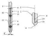
- FIG. 1shows a partial longitudinal section through an intramedullary nail slotted at the distal end
- FIG. 2shows a partial longitudinal section according to FIG. 1 with inserted locking elements
- FIG. 3shows a partial longitudinal section according to FIG. 2 , rotated by 90°;
- FIG. 4shows a partial longitudinal section according to FIG. 2 with an additional transverse hole
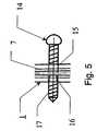
- FIG. 5shows an enlarged section of FIG. 4 in the region of the additional transverse hole
- FIG. 6shows a partial longitudinal section through an intramedullary nail slotted in the proximal end, with a targeting yoke placed on it;
- FIG. 7shows a partial longitudinal section according to FIG. 6 , rotated by 90°
- FIG. 8shows a partial longitudinal section according to FIG. 7 with an inserted locking element and the targeting yoke removed;
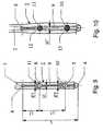
- FIG. 9shows a partial longitudinal section through an intramedullary nail having an unopened slot in the distal part
- FIG. 10shows a partial longitudinal section according to FIG. 7 with inserted locking elements
- FIG. 11shows a partial longitudinal section through an intramedullary nail slotted in the distal part, with a slot protection.
- the diameter d 10 of the hole 10 situated closer to the open end of the longitudinal slot 9is somewhat larger than the diameter d 11 of the other hole 11 .
- Both holes 10 , 11have a centre 5 , 6 , respectively.
- the longitudinal slot 9extends from its opening situated at the distal end 4 through both holes 10 , 11 slightly further to the proximal end up to the base 8 of the slot in the form of a small hole having a very small diameter.
- the distance between the base 8 of the slot and the centre 6 of the hole 11is L 2 . The greater L 2 , the more flexible the intramedullary nail.
- L 1The distance between the two centres 5 , 6 of the two holes 10 , 11 is L 1 .
- L 1is approx. 30 mm.
- the intramedullary nail 1has a continuous cannulation 7 , extending coaxially with the longitudinal axis 2 .
- two locking elements 12 , 13can be introduced in the form of bone screws through the two holes 10 , 11 .
- an expansion of the longitudinal slot 9takes place, so that at the open end of the longitudinal slot its width increases from b to b′>b.
- the shaft of both locking elements 12 , 13has a diameter D 10 , D 11 , corresponding to at least 1.1 times, and preferably 1.2 times, the diameter of the corresponding holes 10 , 11 , so that after the introduction of the two locking elements 12 , 13 into the holes 10 , 11 the intramedullary nail 1 is elastically expanded in the region of its longitudinal slot 9 , as illustrated in FIG. 4 .
- FIG. 4illustrates a variation of the intramedullary nail 1 , whereby an additional third hole 15 is provided between the two holes 10 , 11 .
- the hole 15is oriented 90° relative to the two other holes 10 , 11 .
- an additional locking element 14in the form of a locking screw, can be introduced into this additional hole 15 .
- an inner thread 16is provided, that is engaged by the outside thread 17 of the locking element 14 , so that the intramedullary nail 1 is held together again in the slotted region by means of the locking element 14 .
- FIGS. 6-8illustrate a variation of the intramedullary nail 1 , whereby the longitudinal slot 9 is provided not at the distal end 4 , but at the proximal end 3 of the intramedullary nail 1 .
- a single hole 10is provided to accommodate a single locking element 13 in the form of a locking screw. Otherwise this execution corresponds to that according to FIGS. 1 and 2 for a distally slotted intramedullary nail 1 .
- FIG. 6illustrates, the insertion of the locking element 13 into the hole 10 is carried out with the target yoke 18 in place; on this occasion, the slotted proximal end of the intramedullary nail 1 is expanded, as indicated by arrows 22 ( FIG. 7 ), by the connecting screw 19 , so that the locking element 13 , having larger dimensions than the hole 10 , can be inserted in the hole without any problem.
- the connecting screw 19is subsequently released, so that the target yoke 18 can be removed.
- the slotted intramedullary nail 1attempts to contract again at the proximal end 3 as indicated by arrows 21 ( FIG. 8 ), and consequently secures the inserted locking element 13 in the hole 10 in an angularly stable manner.
- FIGS. 9 and 10illustrate a further variation of the intramedullary nail 1 , whereby the distal slot 9 is closed at both of its ends, i.e. it is not opened at the distal end 4 of the intramedullary nail 1 as is the case for the embodiments according to FIGS. 1-4 .
- the longitudinal slot 9expands from its initial width b 1 to a width of b 1 ′ when the locking elements 12 and 13 are introduced into the holes 10 and 11 .
- the expanded longitudinal slot 9exerts a permanent clamping force on both locking elements 12 and 13 in the holes 10 and 11 , so that they can be securely held in them.
- the longer Lis, the more flexible the intramedullary nail and the simpler its insertion.
- L 1can be individually adapted to suit and has no influence on the function.
- the longer L 2the simpler the introduction of the locking elements 12 and 13 and the weaker is their angular stability. Otherwise this execution corresponds to the embodiment according to FIGS. 1-4 .
- FIG. 11illustrates a further variation of the intramedullary nail 1 , whereby the distal slot 9 is not continuously straight, i.e. extends coaxially with the longitudinal axis 2 , but is bent shortly before the distal end 4 , so that the slot 9 terminates laterally (on the right in this case).
- a protection 23 , 24is realized of the “dovetail” kind that limits the expansion of the slot 9 .
- the right portion 23 of the intramedullary nail 1 with its oblique endabuts against the correspondingly oblique end 24 of the left bent portion 24 of the intramedullary nail 1 , and consequently prevents a further, excessive expansion of the intramedullary nail at its distal part.
Landscapes
- Health & Medical Sciences (AREA)
- Orthopedic Medicine & Surgery (AREA)
- Surgery (AREA)
- Life Sciences & Earth Sciences (AREA)
- Heart & Thoracic Surgery (AREA)
- Nuclear Medicine, Radiotherapy & Molecular Imaging (AREA)
- Engineering & Computer Science (AREA)
- Biomedical Technology (AREA)
- Medical Informatics (AREA)
- Molecular Biology (AREA)
- Animal Behavior & Ethology (AREA)
- General Health & Medical Sciences (AREA)
- Public Health (AREA)
- Veterinary Medicine (AREA)
- Neurology (AREA)
- Surgical Instruments (AREA)
Abstract
Description
Claims (18)
Priority Applications (1)
| Application Number | Priority Date | Filing Date | Title |
|---|---|---|---|
| US13/527,241US9814500B2 (en) | 2003-08-29 | 2012-06-19 | Intramedullary nail |
Applications Claiming Priority (1)
| Application Number | Priority Date | Filing Date | Title |
|---|---|---|---|
| PCT/CH2003/000591WO2005020830A1 (en) | 2003-08-29 | 2003-08-29 | Intramedullary nail |
Related Parent Applications (1)
| Application Number | Title | Priority Date | Filing Date |
|---|---|---|---|
| PCT/CH2003/000591ContinuationWO2005020830A1 (en) | 2003-08-29 | 2003-08-29 | Intramedullary nail |
Related Child Applications (1)
| Application Number | Title | Priority Date | Filing Date |
|---|---|---|---|
| US13/527,241ContinuationUS9814500B2 (en) | 2003-08-29 | 2012-06-19 | Intramedullary nail |
Publications (2)
| Publication Number | Publication Date |
|---|---|
| US20060235395A1 US20060235395A1 (en) | 2006-10-19 |
| US8221419B2true US8221419B2 (en) | 2012-07-17 |
Family
ID=34230814
Family Applications (2)
| Application Number | Title | Priority Date | Filing Date |
|---|---|---|---|
| US11/365,998Expired - Fee RelatedUS8221419B2 (en) | 2003-08-29 | 2006-02-28 | Intramedullary nail |
| US13/527,241Active2026-11-10US9814500B2 (en) | 2003-08-29 | 2012-06-19 | Intramedullary nail |
Family Applications After (1)
| Application Number | Title | Priority Date | Filing Date |
|---|---|---|---|
| US13/527,241Active2026-11-10US9814500B2 (en) | 2003-08-29 | 2012-06-19 | Intramedullary nail |
Country Status (16)
| Country | Link |
|---|---|
| US (2) | US8221419B2 (en) |
| EP (1) | EP1658013B1 (en) |
| JP (1) | JP4695511B2 (en) |
| KR (1) | KR101004561B1 (en) |
| CN (1) | CN100479775C (en) |
| AR (1) | AR045737A1 (en) |
| AT (1) | ATE418924T1 (en) |
| AU (1) | AU2003254693B2 (en) |
| BR (1) | BR0318444B1 (en) |
| CA (1) | CA2551021C (en) |
| DE (1) | DE50311032D1 (en) |
| ES (1) | ES2319185T3 (en) |
| NZ (1) | NZ545342A (en) |
| PL (1) | PL380266A1 (en) |
| TW (1) | TWI333415B (en) |
| WO (1) | WO2005020830A1 (en) |
Cited By (5)
| Publication number | Priority date | Publication date | Assignee | Title |
|---|---|---|---|---|
| US10136929B2 (en) | 2015-07-13 | 2018-11-27 | IntraFuse, LLC | Flexible bone implant |
| US10154863B2 (en) | 2015-07-13 | 2018-12-18 | IntraFuse, LLC | Flexible bone screw |
| US10485595B2 (en) | 2015-07-13 | 2019-11-26 | IntraFuse, LLC | Flexible bone screw |
| US10499960B2 (en) | 2015-07-13 | 2019-12-10 | IntraFuse, LLC | Method of bone fixation |
| US10610270B2 (en) | 2018-01-15 | 2020-04-07 | Glw, Inc. | Hybrid intramedullary rods |
Families Citing this family (32)
| Publication number | Priority date | Publication date | Assignee | Title |
|---|---|---|---|---|
| EP1601297B1 (en)* | 2003-03-07 | 2013-07-17 | Synthes GmbH | Locking screw for an intramedullary nail |
| ATE477757T1 (en)* | 2003-03-21 | 2010-09-15 | Synthes Gmbh | INTRAMEDULLARY NAIL |
| ES2348003T3 (en)* | 2003-06-12 | 2010-11-26 | Synthes Gmbh | SURGICAL KEY. |
| WO2004110291A1 (en)* | 2003-06-12 | 2004-12-23 | Synthes Ag Chur | Surgical nail |
| ES2319179T3 (en)* | 2003-07-30 | 2009-05-05 | Synthes Gmbh | SURGICAL KEY. |
| ES2340479T3 (en)* | 2003-10-21 | 2010-06-04 | Synthes Gmbh | INTRAMEDULAR KEY. |
| ATE426366T1 (en)* | 2004-06-22 | 2009-04-15 | Synthes Gmbh | INTRAMEDULLAR INTRAMEDULLAR NAIL |
| WO2006000109A1 (en)* | 2004-06-24 | 2006-01-05 | Synthes Gmbh | Intramedullary nail |
| CA2571508C (en)* | 2004-06-30 | 2012-03-13 | Synthes (U.S.A.) | Surgical nail |
| FR2884406B1 (en) | 2005-04-14 | 2008-10-17 | Memometal Technologies Soc Par | INTRAMEDULAR OSTEOSYNTHESIS DEVICE OF TWO BONE PARTS, IN PARTICULAR HAND AND / OR FOOT |
| JP5009562B2 (en)* | 2006-07-06 | 2012-08-22 | 株式会社ホムズ技研 | Intramedullary nail and orthopedic surgical instrument set |
| US8303590B2 (en)* | 2007-01-26 | 2012-11-06 | Ebi, Llc | Lockable intramedullary fixation device |
| US8157802B2 (en)* | 2007-01-26 | 2012-04-17 | Ebi, Llc | Intramedullary implant with locking and compression devices |
| US9320551B2 (en) | 2007-01-26 | 2016-04-26 | Biomet Manufacturing, Llc | Lockable intramedullary fixation device |
| US9308031B2 (en) | 2007-01-26 | 2016-04-12 | Biomet Manufacturing, Llc | Lockable intramedullary fixation device |
| FR2913876B1 (en) | 2007-03-20 | 2009-06-05 | Memometal Technologies Soc Par | OSTEOSYNTHESIS DEVICE |
| AU2008256740A1 (en) | 2007-05-25 | 2008-12-04 | Zimmer, Gmbh | Reinforced intramedullary nail |
| US8394103B2 (en)* | 2007-10-16 | 2013-03-12 | Biomet Manufacturing Corp. | Method and apparatus for orthopedic fixation |
| CA2781407A1 (en) | 2008-01-14 | 2009-07-23 | Michael P. Brenzel | Apparatus and methods for fracture repair |
| FR2935601B1 (en) | 2008-09-09 | 2010-10-01 | Memometal Technologies | INTRAMEDULLARY IMPLANT RESORBABLE BETWEEN TWO BONE OR TWO BONE FRAGMENTS |
| ES2524076T3 (en) | 2008-10-15 | 2014-12-04 | Zimmer Gmbh | Intramedullary nail |
| US8435239B2 (en) | 2009-12-17 | 2013-05-07 | Stryker Trauma Gmbh | Encapsulated screw locking system |
| US8377062B2 (en) | 2009-12-17 | 2013-02-19 | Stryker Trauma Gmbh | Therapeutic agent capsule for implants |
| US20110178520A1 (en) | 2010-01-15 | 2011-07-21 | Kyle Taylor | Rotary-rigid orthopaedic rod |
| WO2011091052A1 (en) | 2010-01-20 | 2011-07-28 | Kyle Taylor | Apparatus and methods for bone access and cavity preparation |
| WO2011112615A1 (en) | 2010-03-08 | 2011-09-15 | Krinke Todd A | Apparatus and methods for securing a bone implant |
| US9351771B2 (en)* | 2013-02-08 | 2016-05-31 | Robert Gorsline | Systems, methods, and apparatuses for fusion, stabilization, or fixation of bones |
| CN105939677A (en) | 2013-12-12 | 2016-09-14 | 康文图斯整形外科公司 | Tissue displacement tools and methods |
| US9757168B2 (en) | 2015-03-03 | 2017-09-12 | Howmedica Osteonics Corp. | Orthopedic implant and methods of implanting and removing same |
| EP3251621B1 (en) | 2016-06-03 | 2021-01-20 | Stryker European Holdings I, LLC | Intramedullary implant |
| WO2019010252A2 (en) | 2017-07-04 | 2019-01-10 | Conventus Orthopaedics, Inc. | APPARATUS AND METHODS FOR TREATING BONES |
| CN112190322A (en)* | 2019-07-08 | 2021-01-08 | 彭志军 | Fracture joint bidirectional expansion connecting mechanism and application method thereof |
Citations (92)
| Publication number | Priority date | Publication date | Assignee | Title |
|---|---|---|---|---|
| US2834342A (en) | 1956-08-29 | 1958-05-13 | Clyde E Yost | Surgical device for the fixation of fractured bones |
| US3255747A (en) | 1960-09-01 | 1966-06-14 | Orthopaedic Specialties Corp | Apparatus for treatment of bone fracture |
| US3433220A (en) | 1966-12-30 | 1969-03-18 | Robert E Zickel | Intramedullary rod and cross-nail assembly for treating femur fractures |
| US4095591A (en) | 1977-01-27 | 1978-06-20 | Richards Manufacturing Co., Inc. | Compression screw system |
| US4103683A (en) | 1977-06-03 | 1978-08-01 | Neufeld John A | Sub-trochanteric nail |
| US4172452A (en) | 1978-05-15 | 1979-10-30 | Howmedica, Inc. | Fracture nail plate assembly |
| US4274163A (en) | 1979-07-16 | 1981-06-23 | The Regents Of The University Of California | Prosthetic fixation technique |
| US4438762A (en) | 1981-12-30 | 1984-03-27 | Richard F. Kyle | Orthopedic hip fixation device |
| US4494535A (en) | 1981-06-24 | 1985-01-22 | Haig Armen C | Hip nail |
| US4612920A (en) | 1984-11-06 | 1986-09-23 | Zimmer, Inc. | Compression hip screw |
| US4621628A (en) | 1983-09-09 | 1986-11-11 | Ortopedia Gmbh | Apparatus for locating transverse holes of intramedullary implantates |
| US4622959A (en) | 1985-03-05 | 1986-11-18 | Marcus Randall E | Multi-use femoral intramedullary nail |
| US4628920A (en)* | 1983-12-12 | 1986-12-16 | Synthes Ltd. | Intramedullary nail |
| US4657001A (en) | 1984-07-25 | 1987-04-14 | Fixel Irving E | Antirotational hip screw |
| US4697585A (en) | 1985-01-11 | 1987-10-06 | Williams Michael O | Appliance for fixing fractures of the femur |
| US4705027A (en) | 1984-05-14 | 1987-11-10 | Synthes Ltd. (U.S.A.) | Intramedullary nail |
| EP0251583A2 (en) | 1986-06-23 | 1988-01-07 | Howmedica Inc. | Modular femoral fixation system |
| US4754749A (en) | 1986-04-29 | 1988-07-05 | Tsou Paul M | Surgical screw with counter-rotation prevention means |
| US4791918A (en) | 1985-09-28 | 1988-12-20 | Christoph Von Hasselbach | Femoral-neck implant |
| GB2209947A (en) | 1987-09-23 | 1989-06-01 | Halder Dr Subhash Chandra | Device for fixing femur fractures |
| US4928679A (en)* | 1987-07-21 | 1990-05-29 | Landos Applications Orthopediques Francaises | Centro-medullary nailing rod |
| CH674613A5 (en) | 1988-03-14 | 1990-06-29 | Synthes Ag | |
| EP0381462A2 (en) | 1989-02-02 | 1990-08-08 | Howmedica Inc. | Apparatus for treating a fracture |
| US4973332A (en) | 1988-09-12 | 1990-11-27 | Hospital For Joint Diseases | Attachment for femur sliding screw plate |
| US4978349A (en)* | 1989-08-03 | 1990-12-18 | Synthes (U.S.A.) | Fixation plate |
| US5032125A (en) | 1990-02-06 | 1991-07-16 | Smith & Nephew Richards Inc. | Intramedullary hip screw |
| US5120171A (en) | 1990-11-27 | 1992-06-09 | Stuart Surgical | Bone screw with improved threads |
| US5167663A (en) | 1986-12-30 | 1992-12-01 | Smith & Nephew Richards Inc. | Femoral fracture device |
| US5176681A (en) | 1987-12-14 | 1993-01-05 | Howmedica International Inc. | Intramedullary intertrochanteric fracture fixation appliance and fitting device |
| US5224805A (en)* | 1991-12-09 | 1993-07-06 | A. Raymond & Cie | Anchoring plug |
| WO1993015679A1 (en) | 1992-02-13 | 1993-08-19 | Dietmar Pennig | Medullary nail |
| US5300074A (en) | 1990-12-17 | 1994-04-05 | Synthes (U.S.A.) | Two-part angle plate |
| US5312406A (en) | 1986-12-30 | 1994-05-17 | Smith & Nephew Richards Inc. | Method of treating an intertrochanteric fracture |
| US5454813A (en) | 1991-06-24 | 1995-10-03 | Howmedica International Inc. | Intramedullary intertrochanteric fracture fixation appliance |
| US5484439A (en) | 1992-09-16 | 1996-01-16 | Alphatec Manufacturing, Inc. | Modular femur fixation device |
| WO1996015737A1 (en) | 1994-11-19 | 1996-05-30 | Merck Patent Gmbh | Joint prosthesis |
| US5549610A (en) | 1994-10-31 | 1996-08-27 | Smith & Nephew Richards Inc. | Femoral intramedullary nail |
| US5573536A (en) | 1991-08-09 | 1996-11-12 | Howmedica Gmbh | Locking nail for treating femoral fractures |
| US5578035A (en) | 1995-05-16 | 1996-11-26 | Lin; Chih-I | Expandable bone marrow cavity fixation device |
| US5591168A (en) | 1993-10-25 | 1997-01-07 | Tornier S.A. | Device for stabilizing fractures of the upper end of the femur |
| JPH0966060A (en) | 1995-08-31 | 1997-03-11 | Mizuho Ika Kogyo Kk | Intramedullary nail |
| JPH0966059A (en) | 1995-08-31 | 1997-03-11 | Mizuho Ika Kogyo Kk | Intramedullary nail |
| JPH0966061A (en) | 1995-08-31 | 1997-03-11 | Mizuho Ika Kogyo Kk | Intramedullary nail |
| US5658339A (en) | 1996-01-05 | 1997-08-19 | Wright Medical Technology, Inc. | Compression hip screw plate |
| US5658287A (en) | 1995-06-05 | 1997-08-19 | Gruppo Industriale Bioimpianti S.R.L. | Locked intramedullary nail, suitable in particular for fractures of the femur |
| WO1997037606A1 (en) | 1996-04-05 | 1997-10-16 | Antonio Chemello | Intramedullary nail for the osteosynthesis of bone fractures |
| DE19629011A1 (en) | 1996-07-18 | 1998-01-22 | Wolter Dietmar Prof Dr Med | Auxiliary for promoting osteo-synthesis |
| US5713901A (en) | 1993-07-30 | 1998-02-03 | Tock; Gideon Raphael | Reticulated orthopaedic element to exploit the medullary canal of the long bones |
| US5713902A (en) | 1993-06-01 | 1998-02-03 | Endocare Ag | Osteosynthesis auxiliary for the treatment of subtrochanteric peritrochanteric and femoral-neck fractures |
| WO1998005263A1 (en) | 1996-07-31 | 1998-02-12 | Synthes Ag Chur | Device for attaching fractured hip-joint heads |
| US5728099A (en) | 1994-02-21 | 1998-03-17 | Collux A.B. | Implant |
| US5741256A (en) | 1997-01-13 | 1998-04-21 | Synthes (U.S.A.) | Helical osteosynthetic implant |
| EP0838199A1 (en) | 1996-10-24 | 1998-04-29 | Hit Medica S.r.l. | Nail for reducing fractures of the trochanter and of the neck of the femur |
| EP0845245A2 (en) | 1996-11-22 | 1998-06-03 | Howmedica GmbH | A locking marrow nail with adjustable openings for locking screws |
| EP0853923A1 (en) | 1997-01-21 | 1998-07-22 | ORTHOFIX S.r.l. | Intramedullary cavity nail for the treatment of fractures of the hip |
| WO1998041161A2 (en) | 1997-03-19 | 1998-09-24 | Osteo Ag | Modular intramedullary nail |
| WO1998046169A1 (en) | 1997-04-15 | 1998-10-22 | Limber Ltd. | Bone-growth promoting implant |
| JPH11137566A (en) | 1997-11-12 | 1999-05-25 | Mizuho Ika Kogyo Kk | Intramedullary nail |
| EP0919200A1 (en) | 1997-11-20 | 1999-06-02 | VM Tech | System for osteosynthesis of the upper extremity of the femur |
| US5935127A (en) | 1997-12-17 | 1999-08-10 | Biomet, Inc. | Apparatus and method for treatment of a fracture in a long bone |
| US5976139A (en) | 1996-07-17 | 1999-11-02 | Bramlet; Dale G. | Surgical fastener assembly |
| US6010506A (en) | 1998-09-14 | 2000-01-04 | Smith & Nephew, Inc. | Intramedullary nail hybrid bow |
| EP0968685A2 (en) | 1998-06-30 | 2000-01-05 | Aesculap AG & Co. KG | Device for treating bone fractures |
| JP2000051225A (en) | 1998-06-02 | 2000-02-22 | Ikushi Yamada | Intramedullary nail and distal side stopping method |
| JP2000051224A (en) | 1998-08-05 | 2000-02-22 | Yoji Murashima | Fixing structure of lug screw used for nail for implant |
| FR2784283A1 (en) | 1998-10-07 | 2000-04-14 | Fournitures Hospitalieres Ind | Medullary osteosynthesis pin has at least one hole with transverse rib to engage with thread of retaining screw |
| US6059785A (en) | 1993-12-07 | 2000-05-09 | Synthes (U.S.A.) | Bone fixation device |
| US6123708A (en)* | 1999-02-03 | 2000-09-26 | Pioneer Laboratories, Inc. | Intramedullary bone fixation rod |
| WO2000067653A1 (en) | 1999-05-11 | 2000-11-16 | S.I.N.A.I. Medical Technologies Ltd. | Universal hip compression device |
| EP1053718A1 (en) | 1999-05-12 | 2000-11-22 | Sulzer Orthopedics Ltd. | Locking nail for the treatment of femoral shaft fractures |
| JP2000342596A (en) | 1999-06-07 | 2000-12-12 | Homuzu Giken:Kk | Intramedullary nail |
| DE19945611A1 (en) | 1999-09-23 | 2001-09-13 | Aesculap Ag & Co Kg | Proximal humerus nail; has shaft with transverse bores to hold fixing pins, with several bores in proximal section offset in height and angles and further bores in distal part |
| US6296645B1 (en) | 1999-04-09 | 2001-10-02 | Depuy Orthopaedics, Inc. | Intramedullary nail with non-metal spacers |
| US6302627B1 (en)* | 1998-01-13 | 2001-10-16 | Roland Reichelt | Multipart dowel for a removable anchor |
| EP1214914A2 (en) | 2000-12-18 | 2002-06-19 | Herbert Bernsteiner | Locking screw for implants |
| WO2002060331A1 (en) | 2001-01-31 | 2002-08-08 | Grampian University Hospitals Nhs Trust | Bone fixture apparatus and jig |
| US6454810B1 (en) | 1996-08-16 | 2002-09-24 | Guenter Lob | Endoprosthesis |
| US20020151898A1 (en) | 1999-10-21 | 2002-10-17 | Sohngen Gary W. | Modular intramedullary nail |
| US20020173792A1 (en) | 1999-04-09 | 2002-11-21 | Depuy Orthopaedics, Inc. | Non-metal inserts for bone support assembly |
| EP1260188A1 (en) | 2001-05-25 | 2002-11-27 | Sulzer Orthopedics Ltd. | Femoral bone nail for implantation in the knee |
| WO2003015649A1 (en) | 2001-08-17 | 2003-02-27 | Tantum Ag | Intramedular osteosynthesis device for repairing lateral fractures of the femur extending to the centre thereof |
| US20030069581A1 (en) | 2001-10-04 | 2003-04-10 | Stinson David T. | Universal intramedullary nails, systems and methods of use thereof |
| US20030114855A1 (en) | 1997-03-19 | 2003-06-19 | Stryker Trauma-Selzach Ag | Modular intramedullary nail |
| US6676348B2 (en)* | 2000-05-30 | 2004-01-13 | Fischerwerke Artur Fischer Gmbh & Co. Kg | Expansion anchor which can be fixed to a panel-type building material |
| US6846141B2 (en)* | 2000-08-08 | 2005-01-25 | Fischerwerke Artur Fischer Gmbh & Co. Kg | Expansion bolt |
| US20060064095A1 (en) | 2003-03-07 | 2006-03-23 | Peter Senn | Locking screw for an intramedullary nail |
| US20060111716A1 (en) | 2003-03-21 | 2006-05-25 | Andre Schlienger | Intramedullary nail |
| US20060149248A1 (en) | 2003-06-12 | 2006-07-06 | Andre Schlienger | Surgical nail |
| US20060161155A1 (en) | 2003-06-12 | 2006-07-20 | Andre Schlienger | Surgical nail |
| US20060189988A1 (en) | 2003-07-30 | 2006-08-24 | Andre Schlienger | Surgical nail |
| US20060241605A1 (en) | 2003-10-21 | 2006-10-26 | Andre Schlienger | Intramedullary nail |
| US7182765B2 (en) | 2001-10-17 | 2007-02-27 | Synthes (Usa) | Bone fixation system |
Family Cites Families (4)
| Publication number | Priority date | Publication date | Assignee | Title |
|---|---|---|---|---|
| CN2253187Y (en)* | 1995-12-30 | 1997-04-30 | 王明才 | Automatic locking pressure internal fixation intramedullary nail |
| CA2452508C (en)* | 1998-10-26 | 2010-09-14 | Expanding Orthopedics Inc. | Expandable orthopedic device |
| DE50015249D1 (en)* | 1999-05-12 | 2008-08-21 | Zimmer Gmbh | Locking nail for the treatment of femoral stem fractures |
| DE10242237B4 (en)* | 2002-09-12 | 2005-08-11 | Daimlerchrysler Ag | Corner connection of a window frame of a motor vehicle door |
- 2003
- 2003-08-29NZNZ545342Apatent/NZ545342A/ennot_activeIP Right Cessation
- 2003-08-29WOPCT/CH2003/000591patent/WO2005020830A1/enactiveApplication Filing
- 2003-08-29KRKR1020067003931Apatent/KR101004561B1/ennot_activeExpired - Fee Related
- 2003-08-29EPEP03818372Apatent/EP1658013B1/ennot_activeExpired - Lifetime
- 2003-08-29JPJP2005508344Apatent/JP4695511B2/ennot_activeExpired - Fee Related
- 2003-08-29AUAU2003254693Apatent/AU2003254693B2/ennot_activeCeased
- 2003-08-29DEDE50311032Tpatent/DE50311032D1/ennot_activeExpired - Lifetime
- 2003-08-29ATAT03818372Tpatent/ATE418924T1/enactive
- 2003-08-29ESES03818372Tpatent/ES2319185T3/ennot_activeExpired - Lifetime
- 2003-08-29PLPL380266Apatent/PL380266A1/enunknown
- 2003-08-29CACA2551021Apatent/CA2551021C/ennot_activeExpired - Fee Related
- 2003-08-29BRBRPI0318444-7Apatent/BR0318444B1/ennot_activeIP Right Cessation
- 2003-08-29CNCNB038270013Apatent/CN100479775C/ennot_activeExpired - Fee Related
- 2004
- 2004-08-18TWTW093124775Apatent/TWI333415B/ennot_activeIP Right Cessation
- 2004-08-27ARARP040103082Apatent/AR045737A1/enunknown
- 2006
- 2006-02-28USUS11/365,998patent/US8221419B2/ennot_activeExpired - Fee Related
- 2012
- 2012-06-19USUS13/527,241patent/US9814500B2/enactiveActive
Patent Citations (107)
| Publication number | Priority date | Publication date | Assignee | Title |
|---|---|---|---|---|
| US2834342A (en) | 1956-08-29 | 1958-05-13 | Clyde E Yost | Surgical device for the fixation of fractured bones |
| US3255747A (en) | 1960-09-01 | 1966-06-14 | Orthopaedic Specialties Corp | Apparatus for treatment of bone fracture |
| US3433220A (en) | 1966-12-30 | 1969-03-18 | Robert E Zickel | Intramedullary rod and cross-nail assembly for treating femur fractures |
| US4095591A (en) | 1977-01-27 | 1978-06-20 | Richards Manufacturing Co., Inc. | Compression screw system |
| US4103683A (en) | 1977-06-03 | 1978-08-01 | Neufeld John A | Sub-trochanteric nail |
| US4172452A (en) | 1978-05-15 | 1979-10-30 | Howmedica, Inc. | Fracture nail plate assembly |
| US4274163A (en) | 1979-07-16 | 1981-06-23 | The Regents Of The University Of California | Prosthetic fixation technique |
| US4494535A (en) | 1981-06-24 | 1985-01-22 | Haig Armen C | Hip nail |
| US4438762A (en) | 1981-12-30 | 1984-03-27 | Richard F. Kyle | Orthopedic hip fixation device |
| US4621628A (en) | 1983-09-09 | 1986-11-11 | Ortopedia Gmbh | Apparatus for locating transverse holes of intramedullary implantates |
| US4628920A (en)* | 1983-12-12 | 1986-12-16 | Synthes Ltd. | Intramedullary nail |
| US4705027A (en) | 1984-05-14 | 1987-11-10 | Synthes Ltd. (U.S.A.) | Intramedullary nail |
| US4817591A (en) | 1984-05-14 | 1989-04-04 | Synthes | Intramedullary nail |
| CH668173A5 (en) | 1984-05-14 | 1988-12-15 | Synthes Ag | DEVICE FOR FIXING TUBE BONE FRACTURES WITH A BONE MARBLE NAIL AND AT LEAST ONE CROSS-BOLT LOCKING. |
| US4657001A (en) | 1984-07-25 | 1987-04-14 | Fixel Irving E | Antirotational hip screw |
| US4612920A (en) | 1984-11-06 | 1986-09-23 | Zimmer, Inc. | Compression hip screw |
| US4697585A (en) | 1985-01-11 | 1987-10-06 | Williams Michael O | Appliance for fixing fractures of the femur |
| US4622959A (en) | 1985-03-05 | 1986-11-18 | Marcus Randall E | Multi-use femoral intramedullary nail |
| US4791918A (en) | 1985-09-28 | 1988-12-20 | Christoph Von Hasselbach | Femoral-neck implant |
| US4754749A (en) | 1986-04-29 | 1988-07-05 | Tsou Paul M | Surgical screw with counter-rotation prevention means |
| US4776330A (en) | 1986-06-23 | 1988-10-11 | Pfizer Hospital Products Group, Inc. | Modular femoral fixation system |
| EP0471418A1 (en) | 1986-06-23 | 1992-02-19 | Howmedica Inc. | Components of a modular femoral fixation system |
| US5772662A (en) | 1986-06-23 | 1998-06-30 | Howmedica Inc. | Femoral fixation system |
| EP0251583A2 (en) | 1986-06-23 | 1988-01-07 | Howmedica Inc. | Modular femoral fixation system |
| US5364398A (en) | 1986-06-23 | 1994-11-15 | Pfizer Hospital Products Group, Inc. | Modular femoral fixation system |
| US5041114A (en) | 1986-06-23 | 1991-08-20 | Pfizer Hospital Products Group, Inc. | Modular femoral fixation system |
| US5312406A (en) | 1986-12-30 | 1994-05-17 | Smith & Nephew Richards Inc. | Method of treating an intertrochanteric fracture |
| US5167663A (en) | 1986-12-30 | 1992-12-01 | Smith & Nephew Richards Inc. | Femoral fracture device |
| US4928679A (en)* | 1987-07-21 | 1990-05-29 | Landos Applications Orthopediques Francaises | Centro-medullary nailing rod |
| GB2209947A (en) | 1987-09-23 | 1989-06-01 | Halder Dr Subhash Chandra | Device for fixing femur fractures |
| US5176681A (en) | 1987-12-14 | 1993-01-05 | Howmedica International Inc. | Intramedullary intertrochanteric fracture fixation appliance and fitting device |
| EP0321170B1 (en) | 1987-12-14 | 1994-11-30 | Howmedica International Inc. | Intramedullary intertrochanteric fracture fixation appliance and fitting device |
| CH674613A5 (en) | 1988-03-14 | 1990-06-29 | Synthes Ag | |
| US5041115A (en) | 1988-03-14 | 1991-08-20 | Synthes (U.S.A.) | Medullary nail for the tibia |
| US4973332A (en) | 1988-09-12 | 1990-11-27 | Hospital For Joint Diseases | Attachment for femur sliding screw plate |
| EP0381462A2 (en) | 1989-02-02 | 1990-08-08 | Howmedica Inc. | Apparatus for treating a fracture |
| EP0411273A1 (en) | 1989-08-03 | 1991-02-06 | Synthes AG, Chur | Osteosynthetic assembly with twist fixation plate |
| US4978349A (en)* | 1989-08-03 | 1990-12-18 | Synthes (U.S.A.) | Fixation plate |
| US5032125A (en) | 1990-02-06 | 1991-07-16 | Smith & Nephew Richards Inc. | Intramedullary hip screw |
| US5120171A (en) | 1990-11-27 | 1992-06-09 | Stuart Surgical | Bone screw with improved threads |
| US5300074A (en) | 1990-12-17 | 1994-04-05 | Synthes (U.S.A.) | Two-part angle plate |
| US5454813A (en) | 1991-06-24 | 1995-10-03 | Howmedica International Inc. | Intramedullary intertrochanteric fracture fixation appliance |
| US5573536A (en) | 1991-08-09 | 1996-11-12 | Howmedica Gmbh | Locking nail for treating femoral fractures |
| US5224805A (en)* | 1991-12-09 | 1993-07-06 | A. Raymond & Cie | Anchoring plug |
| WO1993015679A1 (en) | 1992-02-13 | 1993-08-19 | Dietmar Pennig | Medullary nail |
| US5484439A (en) | 1992-09-16 | 1996-01-16 | Alphatec Manufacturing, Inc. | Modular femur fixation device |
| US5713902A (en) | 1993-06-01 | 1998-02-03 | Endocare Ag | Osteosynthesis auxiliary for the treatment of subtrochanteric peritrochanteric and femoral-neck fractures |
| US5928235A (en) | 1993-06-01 | 1999-07-27 | Endocare Ag | Osteosynthesis auxiliary for the treatment of subtrochanteric, peritrochanteric, and femoral-neck fractures |
| US5713901A (en) | 1993-07-30 | 1998-02-03 | Tock; Gideon Raphael | Reticulated orthopaedic element to exploit the medullary canal of the long bones |
| US5591168A (en) | 1993-10-25 | 1997-01-07 | Tornier S.A. | Device for stabilizing fractures of the upper end of the femur |
| US6059785A (en) | 1993-12-07 | 2000-05-09 | Synthes (U.S.A.) | Bone fixation device |
| US5728099A (en) | 1994-02-21 | 1998-03-17 | Collux A.B. | Implant |
| US5549610A (en) | 1994-10-31 | 1996-08-27 | Smith & Nephew Richards Inc. | Femoral intramedullary nail |
| WO1996015737A1 (en) | 1994-11-19 | 1996-05-30 | Merck Patent Gmbh | Joint prosthesis |
| US5578035A (en) | 1995-05-16 | 1996-11-26 | Lin; Chih-I | Expandable bone marrow cavity fixation device |
| US5658287A (en) | 1995-06-05 | 1997-08-19 | Gruppo Industriale Bioimpianti S.R.L. | Locked intramedullary nail, suitable in particular for fractures of the femur |
| JPH0966061A (en) | 1995-08-31 | 1997-03-11 | Mizuho Ika Kogyo Kk | Intramedullary nail |
| JPH0966059A (en) | 1995-08-31 | 1997-03-11 | Mizuho Ika Kogyo Kk | Intramedullary nail |
| JPH0966060A (en) | 1995-08-31 | 1997-03-11 | Mizuho Ika Kogyo Kk | Intramedullary nail |
| US5658339A (en) | 1996-01-05 | 1997-08-19 | Wright Medical Technology, Inc. | Compression hip screw plate |
| WO1997037606A1 (en) | 1996-04-05 | 1997-10-16 | Antonio Chemello | Intramedullary nail for the osteosynthesis of bone fractures |
| US5976139A (en) | 1996-07-17 | 1999-11-02 | Bramlet; Dale G. | Surgical fastener assembly |
| DE19629011A1 (en) | 1996-07-18 | 1998-01-22 | Wolter Dietmar Prof Dr Med | Auxiliary for promoting osteo-synthesis |
| WO1998005263A1 (en) | 1996-07-31 | 1998-02-12 | Synthes Ag Chur | Device for attaching fractured hip-joint heads |
| US6187007B1 (en) | 1996-07-31 | 2001-02-13 | Synthes (Usa) | Device for attaching fractured hip-joint heads |
| US6454810B1 (en) | 1996-08-16 | 2002-09-24 | Guenter Lob | Endoprosthesis |
| EP0838199A1 (en) | 1996-10-24 | 1998-04-29 | Hit Medica S.r.l. | Nail for reducing fractures of the trochanter and of the neck of the femur |
| EP0845245A2 (en) | 1996-11-22 | 1998-06-03 | Howmedica GmbH | A locking marrow nail with adjustable openings for locking screws |
| WO1998030164A1 (en) | 1997-01-13 | 1998-07-16 | Synthes Ag Chur | Helical osteosynthetic implant |
| US5741256A (en) | 1997-01-13 | 1998-04-21 | Synthes (U.S.A.) | Helical osteosynthetic implant |
| US5908422A (en) | 1997-01-13 | 1999-06-01 | Synthes (U.S.A) | Helical osteosynthetic implant |
| US6126661A (en) | 1997-01-20 | 2000-10-03 | Orthofix S.R.L. | Intramedullary cavity nail and kit for the treatment of fractures of the hip |
| EP0853923A1 (en) | 1997-01-21 | 1998-07-22 | ORTHOFIX S.r.l. | Intramedullary cavity nail for the treatment of fractures of the hip |
| WO1998041161A2 (en) | 1997-03-19 | 1998-09-24 | Osteo Ag | Modular intramedullary nail |
| US20030114855A1 (en) | 1997-03-19 | 2003-06-19 | Stryker Trauma-Selzach Ag | Modular intramedullary nail |
| WO1998046169A1 (en) | 1997-04-15 | 1998-10-22 | Limber Ltd. | Bone-growth promoting implant |
| JPH11137566A (en) | 1997-11-12 | 1999-05-25 | Mizuho Ika Kogyo Kk | Intramedullary nail |
| EP0919200A1 (en) | 1997-11-20 | 1999-06-02 | VM Tech | System for osteosynthesis of the upper extremity of the femur |
| US5935127A (en) | 1997-12-17 | 1999-08-10 | Biomet, Inc. | Apparatus and method for treatment of a fracture in a long bone |
| US6302627B1 (en)* | 1998-01-13 | 2001-10-16 | Roland Reichelt | Multipart dowel for a removable anchor |
| JP2000051225A (en) | 1998-06-02 | 2000-02-22 | Ikushi Yamada | Intramedullary nail and distal side stopping method |
| EP0968685A2 (en) | 1998-06-30 | 2000-01-05 | Aesculap AG & Co. KG | Device for treating bone fractures |
| JP2000051224A (en) | 1998-08-05 | 2000-02-22 | Yoji Murashima | Fixing structure of lug screw used for nail for implant |
| US6010506A (en) | 1998-09-14 | 2000-01-04 | Smith & Nephew, Inc. | Intramedullary nail hybrid bow |
| FR2784283A1 (en) | 1998-10-07 | 2000-04-14 | Fournitures Hospitalieres Ind | Medullary osteosynthesis pin has at least one hole with transverse rib to engage with thread of retaining screw |
| US6123708A (en)* | 1999-02-03 | 2000-09-26 | Pioneer Laboratories, Inc. | Intramedullary bone fixation rod |
| US6296645B1 (en) | 1999-04-09 | 2001-10-02 | Depuy Orthopaedics, Inc. | Intramedullary nail with non-metal spacers |
| US20020173792A1 (en) | 1999-04-09 | 2002-11-21 | Depuy Orthopaedics, Inc. | Non-metal inserts for bone support assembly |
| WO2000067653A1 (en) | 1999-05-11 | 2000-11-16 | S.I.N.A.I. Medical Technologies Ltd. | Universal hip compression device |
| EP1053718A1 (en) | 1999-05-12 | 2000-11-22 | Sulzer Orthopedics Ltd. | Locking nail for the treatment of femoral shaft fractures |
| JP2000342596A (en) | 1999-06-07 | 2000-12-12 | Homuzu Giken:Kk | Intramedullary nail |
| DE19945611A1 (en) | 1999-09-23 | 2001-09-13 | Aesculap Ag & Co Kg | Proximal humerus nail; has shaft with transverse bores to hold fixing pins, with several bores in proximal section offset in height and angles and further bores in distal part |
| US20020151898A1 (en) | 1999-10-21 | 2002-10-17 | Sohngen Gary W. | Modular intramedullary nail |
| US6676348B2 (en)* | 2000-05-30 | 2004-01-13 | Fischerwerke Artur Fischer Gmbh & Co. Kg | Expansion anchor which can be fixed to a panel-type building material |
| US6846141B2 (en)* | 2000-08-08 | 2005-01-25 | Fischerwerke Artur Fischer Gmbh & Co. Kg | Expansion bolt |
| EP1214914A2 (en) | 2000-12-18 | 2002-06-19 | Herbert Bernsteiner | Locking screw for implants |
| WO2002060331A1 (en) | 2001-01-31 | 2002-08-08 | Grampian University Hospitals Nhs Trust | Bone fixture apparatus and jig |
| EP1260188A1 (en) | 2001-05-25 | 2002-11-27 | Sulzer Orthopedics Ltd. | Femoral bone nail for implantation in the knee |
| WO2003015649A1 (en) | 2001-08-17 | 2003-02-27 | Tantum Ag | Intramedular osteosynthesis device for repairing lateral fractures of the femur extending to the centre thereof |
| US20030069581A1 (en) | 2001-10-04 | 2003-04-10 | Stinson David T. | Universal intramedullary nails, systems and methods of use thereof |
| US7182765B2 (en) | 2001-10-17 | 2007-02-27 | Synthes (Usa) | Bone fixation system |
| US20060064095A1 (en) | 2003-03-07 | 2006-03-23 | Peter Senn | Locking screw for an intramedullary nail |
| US20060111716A1 (en) | 2003-03-21 | 2006-05-25 | Andre Schlienger | Intramedullary nail |
| US20060149248A1 (en) | 2003-06-12 | 2006-07-06 | Andre Schlienger | Surgical nail |
| US20060161155A1 (en) | 2003-06-12 | 2006-07-20 | Andre Schlienger | Surgical nail |
| US20060189988A1 (en) | 2003-07-30 | 2006-08-24 | Andre Schlienger | Surgical nail |
| US20060241605A1 (en) | 2003-10-21 | 2006-10-26 | Andre Schlienger | Intramedullary nail |
Non-Patent Citations (4)
| Title |
|---|
| "shape." Merriam-Webster Online Dictionary. 2009. Merriam-Webster Online. Sep. 24, 2009 .* |
| "shape." Merriam-Webster Online Dictionary. 2009. Merriam-Webster Online. Sep. 24, 2009 <http://www.merriam-webster.com/dictionary/shape>.* |
| International Search Report for International Application No. PCT/CH03/00591, mailed May 26, 2004, English language translation of the German language version. |
| International Search Report for International Application No. PCT/CH03/00591, mailed May 26, 2004, German language version. |
Cited By (7)
| Publication number | Priority date | Publication date | Assignee | Title |
|---|---|---|---|---|
| US10136929B2 (en) | 2015-07-13 | 2018-11-27 | IntraFuse, LLC | Flexible bone implant |
| US10154863B2 (en) | 2015-07-13 | 2018-12-18 | IntraFuse, LLC | Flexible bone screw |
| US10485595B2 (en) | 2015-07-13 | 2019-11-26 | IntraFuse, LLC | Flexible bone screw |
| US10492838B2 (en) | 2015-07-13 | 2019-12-03 | IntraFuse, LLC | Flexible bone implant |
| US10499960B2 (en) | 2015-07-13 | 2019-12-10 | IntraFuse, LLC | Method of bone fixation |
| US10610270B2 (en) | 2018-01-15 | 2020-04-07 | Glw, Inc. | Hybrid intramedullary rods |
| US11826083B2 (en) | 2018-01-15 | 2023-11-28 | Glw, Inc. | Hybrid intramedullary rods |
Also Published As
| Publication number | Publication date |
|---|---|
| BR0318444B1 (en) | 2014-10-29 |
| WO2005020830A1 (en) | 2005-03-10 |
| EP1658013A1 (en) | 2006-05-24 |
| CA2551021A1 (en) | 2005-03-10 |
| TW200509853A (en) | 2005-03-16 |
| US20120289961A1 (en) | 2012-11-15 |
| BR0318444A (en) | 2006-08-01 |
| ATE418924T1 (en) | 2009-01-15 |
| JP2007506451A (en) | 2007-03-22 |
| PL380266A1 (en) | 2007-01-08 |
| CN100479775C (en) | 2009-04-22 |
| NZ545342A (en) | 2008-11-28 |
| KR20070004513A (en) | 2007-01-09 |
| US9814500B2 (en) | 2017-11-14 |
| KR101004561B1 (en) | 2011-01-03 |
| US20060235395A1 (en) | 2006-10-19 |
| EP1658013B1 (en) | 2008-12-31 |
| TWI333415B (en) | 2010-11-21 |
| AR045737A1 (en) | 2005-11-09 |
| ES2319185T3 (en) | 2009-05-05 |
| CA2551021C (en) | 2012-03-27 |
| AU2003254693A1 (en) | 2005-03-16 |
| AU2003254693B2 (en) | 2009-01-08 |
| CN1826086A (en) | 2006-08-30 |
| DE50311032D1 (en) | 2009-02-12 |
| JP4695511B2 (en) | 2011-06-08 |
Similar Documents
| Publication | Publication Date | Title |
|---|---|---|
| US8221419B2 (en) | Intramedullary nail | |
| JP4357478B2 (en) | Surgical nail | |
| AU771408B2 (en) | Intramedullary nail | |
| US9603641B2 (en) | Device for osteosynthesis | |
| JP4417328B2 (en) | Surgical nail | |
| US4457301A (en) | Intramedullary fixation device | |
| US20060254784A1 (en) | Longitudinal support | |
| US20080009869A1 (en) | Intramedullary nail | |
| AU2003269665B2 (en) | Intramedullary nail | |
| AU2021250995B2 (en) | Modular tensioned spinal screw | |
| US20070100343A1 (en) | Intramedullary nail assembly | |
| EP2695583A1 (en) | Intramedullary nail | |
| JP4714733B2 (en) | Bonding rod for bone bonding element | |
| WO2001017445A1 (en) | Bone splint | |
| JP2007506446A (en) | Surgical nail | |
| WO2009154229A1 (en) | Intramedullary nail and intramedullary nail main body | |
| KR20140099540A (en) | Self holding feature for a screw | |
| ZA200601384B (en) | Intramedullary nail |
Legal Events
| Date | Code | Title | Description |
|---|---|---|---|
| AS | Assignment | Owner name:SYNTHES GMBH, SWITZERLAND Free format text:ASSIGNMENT OF ASSIGNORS INTEREST;ASSIGNORS:FRIGG, ROBERT;FUHRER, MARCEL;SIGNING DATES FROM 20060210 TO 20060322;REEL/FRAME:017633/0752 Owner name:SYNTHES GMBH, SWITZERLAND Free format text:ASSIGNMENT OF ASSIGNORS INTEREST;ASSIGNORS:FRIGG, ROBERT;FUHRER, MARCEL;REEL/FRAME:017633/0752;SIGNING DATES FROM 20060210 TO 20060322 | |
| AS | Assignment | Owner name:SYNTHES (USA), PENNSYLVANIA Free format text:ASSIGNMENT OF ASSIGNORS INTEREST;ASSIGNOR:SYNTHES GMBH;REEL/FRAME:017797/0967 Effective date:20060609 | |
| AS | Assignment | Owner name:HFSC COMPANY, PENNSYLVANIA Free format text:ASSIGNMENT OF ASSIGNORS INTEREST;ASSIGNOR:SYNTHES (USA);REEL/FRAME:017922/0772 Effective date:20060623 | |
| AS | Assignment | Owner name:SYNTHES (USA),PENNSYLVANIA Free format text:ASSIGNMENT OF ASSIGNORS INTEREST;ASSIGNOR:HFSC COMPANY;REEL/FRAME:018280/0469 Effective date:20060920 Owner name:SYNTHES (USA), PENNSYLVANIA Free format text:ASSIGNMENT OF ASSIGNORS INTEREST;ASSIGNOR:HFSC COMPANY;REEL/FRAME:018280/0469 Effective date:20060920 | |
| AS | Assignment | Owner name:SYNTHES USA, LLC, PENNSYLVANIA Free format text:CHANGE OF NAME;ASSIGNOR:SYNTHES (U.S.A.);REEL/FRAME:022398/0364 Effective date:20081231 Owner name:SYNTHES USA, LLC,PENNSYLVANIA Free format text:CHANGE OF NAME;ASSIGNOR:SYNTHES (U.S.A.);REEL/FRAME:022398/0364 Effective date:20081231 | |
| FEPP | Fee payment procedure | Free format text:PAYOR NUMBER ASSIGNED (ORIGINAL EVENT CODE: ASPN); ENTITY STATUS OF PATENT OWNER: LARGE ENTITY | |
| ZAAA | Notice of allowance and fees due | Free format text:ORIGINAL CODE: NOA | |
| ZAAB | Notice of allowance mailed | Free format text:ORIGINAL CODE: MN/=. | |
| STCF | Information on status: patent grant | Free format text:PATENTED CASE | |
| CC | Certificate of correction | ||
| FPAY | Fee payment | Year of fee payment:4 | |
| MAFP | Maintenance fee payment | Free format text:PAYMENT OF MAINTENANCE FEE, 8TH YEAR, LARGE ENTITY (ORIGINAL EVENT CODE: M1552); ENTITY STATUS OF PATENT OWNER: LARGE ENTITY Year of fee payment:8 | |
| FEPP | Fee payment procedure | Free format text:MAINTENANCE FEE REMINDER MAILED (ORIGINAL EVENT CODE: REM.); ENTITY STATUS OF PATENT OWNER: LARGE ENTITY | |
| LAPS | Lapse for failure to pay maintenance fees | Free format text:PATENT EXPIRED FOR FAILURE TO PAY MAINTENANCE FEES (ORIGINAL EVENT CODE: EXP.); ENTITY STATUS OF PATENT OWNER: LARGE ENTITY | |
| STCH | Information on status: patent discontinuation | Free format text:PATENT EXPIRED DUE TO NONPAYMENT OF MAINTENANCE FEES UNDER 37 CFR 1.362 | |
| FP | Lapsed due to failure to pay maintenance fee | Effective date:20240717 |