US8221161B2 - Break-away adapter - Google Patents
Break-away adapterDownload PDFInfo
- Publication number
- US8221161B2 US8221161B2US12/861,359US86135910AUS8221161B2US 8221161 B2US8221161 B2US 8221161B2US 86135910 AUS86135910 AUS 86135910AUS 8221161 B2US8221161 B2US 8221161B2
- Authority
- US
- United States
- Prior art keywords
- contact
- adapter
- connector assembly
- locking sleeve
- receptacle body
- Prior art date
- Legal status (The legal status is an assumption and is not a legal conclusion. Google has not performed a legal analysis and makes no representation as to the accuracy of the status listed.)
- Expired - Fee Related
Links
- 239000004020conductorSubstances0.000claimsdescription16
- 239000012212insulatorSubstances0.000claimsdescription14
- 239000002184metalSubstances0.000description3
- 230000001066destructive effectEffects0.000description2
- 230000013011matingEffects0.000description2
- 230000007704transitionEffects0.000description2
- 238000010276constructionMethods0.000description1
- 230000001351cycling effectEffects0.000description1
- 230000001419dependent effectEffects0.000description1
- 230000007613environmental effectEffects0.000description1
- 230000003116impacting effectEffects0.000description1
- 238000003780insertionMethods0.000description1
- 230000037431insertionEffects0.000description1
- 239000000463materialSubstances0.000description1
- 238000012986modificationMethods0.000description1
- 230000004048modificationEffects0.000description1
Images


Classifications
- H—ELECTRICITY
- H01—ELECTRIC ELEMENTS
- H01R—ELECTRICALLY-CONDUCTIVE CONNECTIONS; STRUCTURAL ASSOCIATIONS OF A PLURALITY OF MUTUALLY-INSULATED ELECTRICAL CONNECTING ELEMENTS; COUPLING DEVICES; CURRENT COLLECTORS
- H01R13/00—Details of coupling devices of the kinds covered by groups H01R12/70 or H01R24/00 - H01R33/00
- H01R13/62—Means for facilitating engagement or disengagement of coupling parts or for holding them in engagement
- H01R13/627—Snap or like fastening
- H01R13/6277—Snap or like fastening comprising annular latching means, e.g. ring snapping in an annular groove
- H—ELECTRICITY
- H01—ELECTRIC ELEMENTS
- H01R—ELECTRICALLY-CONDUCTIVE CONNECTIONS; STRUCTURAL ASSOCIATIONS OF A PLURALITY OF MUTUALLY-INSULATED ELECTRICAL CONNECTING ELEMENTS; COUPLING DEVICES; CURRENT COLLECTORS
- H01R24/00—Two-part coupling devices, or either of their cooperating parts, characterised by their overall structure
- H01R24/38—Two-part coupling devices, or either of their cooperating parts, characterised by their overall structure having concentrically or coaxially arranged contacts
- H01R24/40—Two-part coupling devices, or either of their cooperating parts, characterised by their overall structure having concentrically or coaxially arranged contacts specially adapted for high frequency
- H01R24/54—Intermediate parts, e.g. adapters, splitters or elbows
- H01R24/542—Adapters
- H—ELECTRICITY
- H01—ELECTRIC ELEMENTS
- H01R—ELECTRICALLY-CONDUCTIVE CONNECTIONS; STRUCTURAL ASSOCIATIONS OF A PLURALITY OF MUTUALLY-INSULATED ELECTRICAL CONNECTING ELEMENTS; COUPLING DEVICES; CURRENT COLLECTORS
- H01R2101/00—One pole
- H—ELECTRICITY
- H01—ELECTRIC ELEMENTS
- H01R—ELECTRICALLY-CONDUCTIVE CONNECTIONS; STRUCTURAL ASSOCIATIONS OF A PLURALITY OF MUTUALLY-INSULATED ELECTRICAL CONNECTING ELEMENTS; COUPLING DEVICES; CURRENT COLLECTORS
- H01R2103/00—Two poles
Definitions
- the present inventionis directed to an adapter for use with a coaxial connector.
- the adapterallows the male portion of the connector to be disengaged when a pre-determined force is applied thereto.
- the adapteris used to convert a standard threaded coupled connector into a push-on and break-away connector.
- Coaxial connectors for radio frequency (rf) signalsare known. Such connectors are typically used with a coaxial cable containing an external conductor/shield surrounding one or more internal conductors.
- the coaxial connectorfunctions to align and provide an electrical path to the respective ends of the conductors while providing a continuous shield to minimize rf leakage.
- These connectorsgenerally include a female portion and a male portion.
- the male portioncontains the conductor interface and a threaded nut used to engage the female portion.
- the female portionincludes a tubular housing that functions to accept the conductor interface of the male portion and align the conductor interface with a mating rf conductor held within the female portion.
- the tubular housing of the female portionis provided with an external thread to accept the threaded nut of the male portion.
- One aspect of the inventionis directed to an adapter for use with a threaded connector assembly.
- the adapterhas a receptacle body and a locking sleeve.
- the receptacle bodyis applied to a first portion of the connector assembly, and the locking sleeve is applied to a second portion of the connector assembly.
- the locking sleevecan be easily disengaged from the receptacle body to remove the second portion or the connector assembly from the first portion.
- the resiliency of the mounting projectionscauses the mounting projections to exert sufficient force on the second portion to insure that a positive physical and electrical connection is provided between the locking sleeve and the second portion.
- the locking sleeve of the adaptercan be easily engaged and disengaged from the second portion of the connector assembly. This allows for the threaded connector assembly to be converted to a break-away style connector assembly, such that a force applied or translated to the first portion or the second portion of the connector assembly causes the adapter to disengage the second portion, allowing the second portion to be separated from the adapter and the first portion attached thereto without damaging the adapter, the first portion or the second portion.
- FIG. 1is a cut-away side view of an adapter for use with a coaxial connector combination in accordance with an illustrated embodiment of the invention.
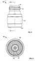
- FIG. 3is a side view of the assembled adapter.
- FIG. 4is a front view of the assembled adapter.
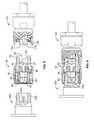
- FIG. 5is a partial cross-sectional view of a male portion of a coax connector, the adapter and a female portion of the coax connector prior to assembly.
- FIG. 6is a partial cross-sectional view of the male portion of a coax connector, the adapter and the female portion of the coax connector of FIG. 5 in the assembled position.
- an adapter 10 for use with an N-series coax connector 100 , 200( FIGS. 5 and 6 ) is disclosed.
- the adapter 10has a receptacle body 12 , a coaxial contact assembly 14 , a gasket 16 , a locking sleeve 18 and a shell 20 .
- the N-series coax connector to which the adapter 10 is matedis an N-series coax connector known in the art with a known male portion 100 and a known female portion 200 . When mated together, the male portion 100 is threaded to the female portion 200 , thereby securing the male portion to the female portion.
- the N-series coax connectorsare known connectors, such connectors are incorporated herein by reference and a further description of the N-series coax connectors will not be provided.
- the receptacle body 12 of the adapter 10is made from metal or other electrically conductive material which has the strength characteristics required.
- the receptacle body 12has a generally cylindrical configuration.
- a back surface 22 of the receptacle body 12has an opening 24 which is dimensioned to receive a portion of the male portion of the N-series coax connector.
- the opening 24extends from the back surface 22 of the receptacle body 12 to the front surface 26 ( FIG. 2 ).
- the opening 24has sections of different diameters.
- the opening 24Proximate the back surface 22 , the opening 24 has a first section 28 that is dimensioned to receive a shielding portion of a male contact of the male portion therein.
- the diameter of the first section 28is configured to allow the surface surrounding the circumference of the first section 28 to be in electrical engagement with the shielding portion of the male contact, thereby allowing the shielding of the shielding portion of the male contact to be extended through the receptacle body.
- a second section 30 of the opening 24has a smaller diameter than the first section 28 .
- the diameter of the second section 30approximates the diameter of the shielding portion of the male contact.
- the transition between the first section 28 and the second section 30also provides a shoulder 32 on which the shielding portion of the male contact will abut to provide a positive positioning of the male contact relative to the receptacle body 12 .
- the contact assembly 14is of a coaxial construction and has an inner contact 48 , an outer contact 50 and an insulator 36 .
- the inner contact 48has a front portion 52 which is configured to be essentially the same as the male contact into which the adapter is inserted.
- a rear portion 54 of the inner contact 48has slits 56 extending from a back surface 58 toward the front portion 52 .
- the slits 56define individual resilient legs 60 .
- the resilient legs 60are provided to deflect away from the longitudinal axis of the inner contact 48 when the inner contact 48 is inserted over the male contact of the male portion of the connector.
- a mounting shoulder 62is provided on the inner contact 48 between the front portion 52 and the rear portion 54 . The mounting shoulder 62 cooperates with the insulator 36 to properly position the insulator 36 .
- the insulator 36has a generally circular cross-section.
- the insulator 36has an opening 64 extending through the longitudinal axis thereof.
- the opening 64is dimensioned to receive the inner contact 48 therein. As best shown in FIG. 1 , when the insulator 36 is inserted into the receptacle body 12 , the insulator 36 is positioned and maintained in the third section 34 of the opening 24 .
- the outer contact 50 of the contact assembly 14has a mounting ring 66 with resilient contact arms 68 extending therefrom.
- the contact arms 68are separated by slits or openings 70 .
- the mounting ring 66when assembled, the mounting ring 66 is positioned in engagement with the insulator 36 and is maintained in position relative to the receptacle body 12 in the outer contact-receiving recess 46 .
- the resilient contact arms 68are provided to deflect from the longitudinal axis of the outer contact 50 when the outer contact 50 is inserted on the female contact of the female portion of the connector. This allows the resilient contact arms 68 of the outer contact 50 to exert sufficient force on the female contact to insure that a positive electrical connection is provided between the outer contact 50 and the female contact.
- the gasket or washer 16having a generally circular cross-section is provided.
- the gasket 16has a center opening 72 which is dimensioned to be inserted over the resilient contact arms 68 of the outer contact 50 .
- the gasket 16is inserted into the receptacle body 12 through the front surface 26 and is positioned proximate the mounting ring 66 of the outer contact 50 .
- the locking sleeve 18has a mounting collar 74 and resilient mounting legs 76 which extend therefrom.
- the resilient mounting legs 76are separated by slits 78 which extend from a first end 80 of the locking sleeve 18 toward the mounting collar 74 .
- the mounting legs 76have shoulders 82 proximate the free ends thereof.
- the shoulders 82extend inward from the mounting legs 76 to form mounting projections.
- Tapered surfaces 84are provided proximate the shoulders or mounting projections 82 . As shown in FIG.
- the shell 20has a generally cylindrical configuration.
- the shell 20is made from metal or other electrically conductive material which has the strength characteristics required.
- the diameter of an inner opening 86 proximate a back wall 88 of the shell 20is dimensioned such that the shell 20 may be inserted onto the receptacle body 12 over the shell mounting ring 42 . This allows the shell 20 to be moved in a direction parallel to the longitudinal axis of the receptacle body 12 , as is indicated by the arrow of FIG. 1 .
- the inner opening 86has a larger diameter proximate a front wall 90 of the shell, as best shown in FIG. 1 .
- a lead-in surface 92is provided at the front end of the shell 20 . The lead-in surface 92 guides the female portion of the connector into the adapter 10 when the adapter 10 is inserted onto the female portion.
- the adapter 10is inserted onto the male portion 100 and the female portion 200 of the connector.
- the rear portion 54 of the inner contact 48is moved into engagement with the male contact 102 of the male portion 100 .
- Thiscauses the resilient legs 60 of the rear portion 54 of the inner contact 48 to be resiliently deformed outward, causing the resilient legs 60 to exert sufficient force on the male contact 102 to insure that a positive electrical connection is provided between the inner contact 48 and the male contact 102 .
- the second section 30 of the receptacle body opening 24engages a shielding portion 104 of the male portion 100 to provide a physical and electrical engagement therebetween.
- the threads 40 of the receptacle body 12are then threaded onto the oppositely facing threads 106 of the male portion 100 of the connector.
- the resilient contact arms 68 of the outer contact 50are moved into engagement with the female contact 202 of the female portion 200 .
- Thiscauses the resilient contact arms 68 of the outer contact 50 to be resiliently deformed, causing the resilient contact arms 68 to exert sufficient force on the female contact 202 to insure that a positive electrical connection is provided between the outer contact 50 and the female contact 202 .
- the front portion 52 of the inner contact 48is inserted into an opening in the female contact 202 of the female portion 200 to provide a physical and electrical engagement therebetween.
- Threads 204 positioned about an outward-facing cylindrical member of the female portion 200 of the connectorare inserted through the lead-in surface 92 of the shell 20 and into the locking sleeve 18 .
- the locking sleeve 18is dimensioned to allow the threaded portion 204 of the female portion 200 to be inserted between the resilient mounting legs 76 .
- the tapered surfaces 84 of the resilient mounting legs 76facilitate the proper insertion of the threaded portion 204 of the female portion 200 .
- the resilient mounting legs 76 of the locking sleeve 18are moved into engagement with the threaded portion 204 of the female portion 200 of the connector. This causes the resilient mounting legs 76 to be resiliently deformed outward as mounting projections pass over ridges of the threads 204 . This continues until the female portion 200 is properly seated in the adapter 10 . In this position, the shoulders or mounting projections 82 are positioned in a groove between the ridges of the threads 204 .
- the resilient mounting legs 76are deformed slightly, which causes the mounting projections 82 to exert sufficient force on the threads 204 of the female portion 200 to insure that a positive physical connection is provided between the locking sleeve 18 and the female portion 200 .
- the mounting shoulders 82cooperate with the threads 204 of the female portion 200 to prevent the inadvertent removal of the female portion 200 from the adapter 10 .
- a large force applied or translated to the female portion 200 or the male portion 100can cause the threads 204 of the female portion 200 to force the resilient contact legs 76 outward. This causes the mounting projections 82 to be moved out of the grooves, thereby allowing the female portion 200 to be separated from the adapter 10 and the male portion 100 attached thereto.
- One advantage of the inventionis that it allows the female and male portions 200 , 100 to turn independently of each other.
- the shell 20 and locking sleeve 18are mounted to the receptacle body 12 in such a manner as to permit the rotation of the shell 20 and the locking sleeve 18 relative to the receptacle body 12 , twisting or turning forces applied to either of the male or female portion 100 , 200 will not cause the mating portion to be affected. Consequently, the reliability of the connection between the male and female portions of the connector is enhanced by the use of the adapter.
- the adapter 10 of this inventionallows for conventional threaded connectors, such as N-series connectors, to be converted to break-away style connectors. This allows the connectors to be used in environments in which destructive forces may be present. As the adapter allows for the portions to break away from each other, destructive force will not be translated through the connector to the cable attached thereto; thereby reducing the chance that the components attached to the cables will be damaged.
- the adapter 10also allows the user to quickly and easily connect and disconnect connectors. By using the adapter, threaded connectors are easily converted to quick-connect and -disconnect connectors. This can be advantageous in environments in which space and access to the connector are limited.
- the adapter 10may be used in a number of different environments, the adapter may generally be used for aligning and connecting rf conductors. Further, for purposes of illustration but not limitation, the adapter has generally been described in the context of an N-series connector. However, other applications will be readily apparent to those of skill in the art.
Landscapes
- Coupling Device And Connection With Printed Circuit (AREA)
- Details Of Connecting Devices For Male And Female Coupling (AREA)
Abstract
Description
Claims (20)
Priority Applications (1)
| Application Number | Priority Date | Filing Date | Title |
|---|---|---|---|
| US12/861,359US8221161B2 (en) | 2009-08-28 | 2010-08-23 | Break-away adapter |
Applications Claiming Priority (2)
| Application Number | Priority Date | Filing Date | Title |
|---|---|---|---|
| US23793509P | 2009-08-28 | 2009-08-28 | |
| US12/861,359US8221161B2 (en) | 2009-08-28 | 2010-08-23 | Break-away adapter |
Publications (2)
| Publication Number | Publication Date |
|---|---|
| US20110053395A1 US20110053395A1 (en) | 2011-03-03 |
| US8221161B2true US8221161B2 (en) | 2012-07-17 |
Family
ID=43625556
Family Applications (1)
| Application Number | Title | Priority Date | Filing Date |
|---|---|---|---|
| US12/861,359Expired - Fee RelatedUS8221161B2 (en) | 2009-08-28 | 2010-08-23 | Break-away adapter |
Country Status (1)
| Country | Link |
|---|---|
| US (1) | US8221161B2 (en) |
Cited By (19)
| Publication number | Priority date | Publication date | Assignee | Title |
|---|---|---|---|---|
| US20120289083A1 (en)* | 2011-05-12 | 2012-11-15 | Electronics And Telecommunications Research Institute | High-voltage coaxial cable and connector |
| US20120315788A1 (en)* | 2011-06-10 | 2012-12-13 | John Mezzalingua Associates, Inc. | Connector having a coupling member for locking onto a port and maintaining electrical continuity |
| USD695695S1 (en) | 2012-10-25 | 2013-12-17 | Perfectvision Manufacturing, Inc. | Sealing connector boot with mandrel grip |
| US20130344749A1 (en)* | 2012-06-25 | 2013-12-26 | Dish Network L.L.C. | RF Connector with Push-On Connection |
| US8668504B2 (en) | 2011-07-05 | 2014-03-11 | Dave Smith Chevrolet Oldsmobile Pontiac Cadillac, Inc. | Threadless light bulb socket |
| US20140162495A1 (en)* | 2011-08-05 | 2014-06-12 | Illinois Tool Works Inc. | Device for connection of a thermocouple to a safety electromagnet and gas tap assembly in a cooking range |
| US20140273648A1 (en)* | 2012-05-31 | 2014-09-18 | Robert J. Baumler | Modular RF connector system |
| US8992250B1 (en)* | 2013-03-15 | 2015-03-31 | Megaphase, Llc | Clockable cable adapter |
| US9004931B2 (en) | 2011-06-10 | 2015-04-14 | Ppc Broadband, Inc. | Coaxial interface port accessory and port facilitating slide-on attachment and rotational detachment of cable connectors |
| US9054471B2 (en) | 2012-02-03 | 2015-06-09 | Megaphase, Llc | Coaxial angled adapter |
| US9246244B2 (en) | 2012-06-25 | 2016-01-26 | Dish Network L.L.C. | RF connector with push-on connection |
| US9478929B2 (en) | 2014-06-23 | 2016-10-25 | Ken Smith | Light bulb receptacles and light bulb sockets |
| US9762007B2 (en)* | 2016-02-10 | 2017-09-12 | Dish Network L.L.C. | Push on connector |
| US10096955B1 (en)* | 2017-10-02 | 2018-10-09 | The United States Of America As Represented By The Secretary Of The Navy | High voltage radio frequency coaxial cable connector |
| US10218122B1 (en) | 2017-08-09 | 2019-02-26 | Te Connectivity Corporation | Circular connector and method of retaining components |
| US10439323B1 (en)* | 2017-10-02 | 2019-10-08 | The United States Of America, As Represented By The Secretary Of The Navy | High voltage RF connector for coaxial-to-stripline transition |
| US10826230B1 (en)* | 2019-10-31 | 2020-11-03 | Holland Electronics, Llc | Spring mouth connector |
| US20210296821A1 (en)* | 2014-09-19 | 2021-09-23 | Ppc Broadband, Inc. | Breakaway connectors for coaxial cables |
| US20230420894A1 (en)* | 2022-06-28 | 2023-12-28 | Ppc Broadband, Inc. | Push/pull interface for coaxial cables with secure ground connection |
Families Citing this family (5)
| Publication number | Priority date | Publication date | Assignee | Title |
|---|---|---|---|---|
| EP3196987A4 (en)* | 2014-09-19 | 2018-04-25 | Junkosha Inc. | Connector |
| US9966702B2 (en) | 2015-05-01 | 2018-05-08 | Commscope Technologies Llc | Coaxial cable connector interface for preventing mating with incorrect connector |
| CN107565250A (en)* | 2016-06-30 | 2018-01-09 | 泰科电子(上海)有限公司 | Connector |
| CN106099593B (en)* | 2016-07-27 | 2019-11-12 | 广州海格通信集团股份有限公司 | A kind of rotable antenna adapter |
| WO2018184229A1 (en)* | 2017-04-07 | 2018-10-11 | Shanghai Radiall Electronics Co., Ltd. | A slotted contact for a female connector of the jack type for a 4.3-10 coaxial connection system |
Citations (20)
| Publication number | Priority date | Publication date | Assignee | Title |
|---|---|---|---|---|
| US4138181A (en) | 1978-04-25 | 1979-02-06 | The United States Of America As Represented By The Secretary Of The Navy | Releasable electrical connector |
| US4206963A (en)* | 1979-04-20 | 1980-06-10 | Amp Incorporated | Connector filtered adapter assembly |
| US4372624A (en) | 1981-06-04 | 1983-02-08 | Smith International, Inc. | Dynamic O-ring seal |
| US4544224A (en) | 1982-09-07 | 1985-10-01 | International Telephone & Telegraph Corp. | Self-locking electrical connector |
| US4545633A (en) | 1983-07-22 | 1985-10-08 | Whittaker Corporation | Weatherproof positive lock connector |
| US4687279A (en)* | 1985-12-20 | 1987-08-18 | Storm Products Co. | High frequency coaxial connector adaptor |
| US4846731A (en)* | 1988-08-03 | 1989-07-11 | Amp Incorporated | Shielded electrical connectors |
| US4941846A (en)* | 1989-05-31 | 1990-07-17 | Adams-Russell Electronic Company, Inc. | Quick connect/disconnect microwave connector |
| US5062808A (en)* | 1991-04-12 | 1991-11-05 | Amp Incorporated | Adapter for interconnecting socket connectors for triaxial cable |
| US5199893A (en) | 1991-07-22 | 1993-04-06 | Fussell Don L | Seismic connector with replaceable seal |
| US5217391A (en)* | 1992-06-29 | 1993-06-08 | Amp Incorporated | Matable coaxial connector assembly having impedance compensation |
| US5388874A (en) | 1993-05-11 | 1995-02-14 | Barrier; M. M. | Quick connect/disconnect latch screw coupling |
| US6024609A (en)* | 1997-11-03 | 2000-02-15 | Andrew Corporation | Outer contact spring |
| US6619876B2 (en) | 2002-02-18 | 2003-09-16 | Andrew Corporation | Coaxial connector apparatus and method |
| US6692285B2 (en) | 2002-03-21 | 2004-02-17 | Andrew Corporation | Push-on, pull-off coaxial connector apparatus and method |
| US6769926B1 (en)* | 2003-07-07 | 2004-08-03 | John Mezzalingua Associates, Inc. | Assembly for connecting a cable to an externally threaded connecting port |
| US6848931B2 (en) | 2002-07-19 | 2005-02-01 | Andrew Corporation | Quick attachment SMA connector |
| US7189113B2 (en)* | 2004-11-05 | 2007-03-13 | Ims Connector Systems Gmbh | Coaxial plug connector and mating connector |
| US20070270012A1 (en) | 2006-05-03 | 2007-11-22 | Shawn Showcatally | Antenna breakaway device for utility pit meter system |
| US7347726B2 (en)* | 2004-01-23 | 2008-03-25 | Andrew Corporation | Push-on connector interface |
- 2010
- 2010-08-23USUS12/861,359patent/US8221161B2/ennot_activeExpired - Fee Related
Patent Citations (20)
| Publication number | Priority date | Publication date | Assignee | Title |
|---|---|---|---|---|
| US4138181A (en) | 1978-04-25 | 1979-02-06 | The United States Of America As Represented By The Secretary Of The Navy | Releasable electrical connector |
| US4206963A (en)* | 1979-04-20 | 1980-06-10 | Amp Incorporated | Connector filtered adapter assembly |
| US4372624A (en) | 1981-06-04 | 1983-02-08 | Smith International, Inc. | Dynamic O-ring seal |
| US4544224A (en) | 1982-09-07 | 1985-10-01 | International Telephone & Telegraph Corp. | Self-locking electrical connector |
| US4545633A (en) | 1983-07-22 | 1985-10-08 | Whittaker Corporation | Weatherproof positive lock connector |
| US4687279A (en)* | 1985-12-20 | 1987-08-18 | Storm Products Co. | High frequency coaxial connector adaptor |
| US4846731A (en)* | 1988-08-03 | 1989-07-11 | Amp Incorporated | Shielded electrical connectors |
| US4941846A (en)* | 1989-05-31 | 1990-07-17 | Adams-Russell Electronic Company, Inc. | Quick connect/disconnect microwave connector |
| US5062808A (en)* | 1991-04-12 | 1991-11-05 | Amp Incorporated | Adapter for interconnecting socket connectors for triaxial cable |
| US5199893A (en) | 1991-07-22 | 1993-04-06 | Fussell Don L | Seismic connector with replaceable seal |
| US5217391A (en)* | 1992-06-29 | 1993-06-08 | Amp Incorporated | Matable coaxial connector assembly having impedance compensation |
| US5388874A (en) | 1993-05-11 | 1995-02-14 | Barrier; M. M. | Quick connect/disconnect latch screw coupling |
| US6024609A (en)* | 1997-11-03 | 2000-02-15 | Andrew Corporation | Outer contact spring |
| US6619876B2 (en) | 2002-02-18 | 2003-09-16 | Andrew Corporation | Coaxial connector apparatus and method |
| US6692285B2 (en) | 2002-03-21 | 2004-02-17 | Andrew Corporation | Push-on, pull-off coaxial connector apparatus and method |
| US6848931B2 (en) | 2002-07-19 | 2005-02-01 | Andrew Corporation | Quick attachment SMA connector |
| US6769926B1 (en)* | 2003-07-07 | 2004-08-03 | John Mezzalingua Associates, Inc. | Assembly for connecting a cable to an externally threaded connecting port |
| US7347726B2 (en)* | 2004-01-23 | 2008-03-25 | Andrew Corporation | Push-on connector interface |
| US7189113B2 (en)* | 2004-11-05 | 2007-03-13 | Ims Connector Systems Gmbh | Coaxial plug connector and mating connector |
| US20070270012A1 (en) | 2006-05-03 | 2007-11-22 | Shawn Showcatally | Antenna breakaway device for utility pit meter system |
Cited By (30)
| Publication number | Priority date | Publication date | Assignee | Title |
|---|---|---|---|---|
| US8568166B2 (en)* | 2011-05-12 | 2013-10-29 | Electronics And Telecommunications Research Institute | High-voltage coaxial cable and connector |
| US20120289083A1 (en)* | 2011-05-12 | 2012-11-15 | Electronics And Telecommunications Research Institute | High-voltage coaxial cable and connector |
| US20120315788A1 (en)* | 2011-06-10 | 2012-12-13 | John Mezzalingua Associates, Inc. | Connector having a coupling member for locking onto a port and maintaining electrical continuity |
| US8753147B2 (en)* | 2011-06-10 | 2014-06-17 | Ppc Broadband, Inc. | Connector having a coupling member for locking onto a port and maintaining electrical continuity |
| US8758050B2 (en)* | 2011-06-10 | 2014-06-24 | Hiscock & Barclay LLP | Connector having a coupling member for locking onto a port and maintaining electrical continuity |
| US9004931B2 (en) | 2011-06-10 | 2015-04-14 | Ppc Broadband, Inc. | Coaxial interface port accessory and port facilitating slide-on attachment and rotational detachment of cable connectors |
| US9214776B2 (en) | 2011-07-05 | 2015-12-15 | Ken Smith | Light bulb socket having a plurality of thread locks to engage a light bulb |
| US8668504B2 (en) | 2011-07-05 | 2014-03-11 | Dave Smith Chevrolet Oldsmobile Pontiac Cadillac, Inc. | Threadless light bulb socket |
| US9236693B2 (en)* | 2011-08-05 | 2016-01-12 | Illinois Tool Works Inc. | Device for connection of a thermocouple to a safety electromagnet and gas tap assembly in a cooking range |
| US20140162495A1 (en)* | 2011-08-05 | 2014-06-12 | Illinois Tool Works Inc. | Device for connection of a thermocouple to a safety electromagnet and gas tap assembly in a cooking range |
| US9431780B2 (en) | 2012-02-03 | 2016-08-30 | Megaphase, Llc | Coaxial adapter with an adapter body forward projecting member |
| US9054471B2 (en) | 2012-02-03 | 2015-06-09 | Megaphase, Llc | Coaxial angled adapter |
| US8888519B2 (en)* | 2012-05-31 | 2014-11-18 | Cinch Connectivity Solutions, Inc. | Modular RF connector system |
| US20140273648A1 (en)* | 2012-05-31 | 2014-09-18 | Robert J. Baumler | Modular RF connector system |
| US9190786B1 (en) | 2012-05-31 | 2015-11-17 | Cinch Connectivity Solutions Inc. | Modular RF connector system |
| US9106035B2 (en)* | 2012-06-25 | 2015-08-11 | Dish Network L.L.C. | RF connector with push-on connection |
| US20130344749A1 (en)* | 2012-06-25 | 2013-12-26 | Dish Network L.L.C. | RF Connector with Push-On Connection |
| US9246244B2 (en) | 2012-06-25 | 2016-01-26 | Dish Network L.L.C. | RF connector with push-on connection |
| US9748710B2 (en) | 2012-06-25 | 2017-08-29 | Dish Network L.L.C. | RF connector with push-on connection |
| USD695695S1 (en) | 2012-10-25 | 2013-12-17 | Perfectvision Manufacturing, Inc. | Sealing connector boot with mandrel grip |
| US8992250B1 (en)* | 2013-03-15 | 2015-03-31 | Megaphase, Llc | Clockable cable adapter |
| US9478929B2 (en) | 2014-06-23 | 2016-10-25 | Ken Smith | Light bulb receptacles and light bulb sockets |
| US20210296821A1 (en)* | 2014-09-19 | 2021-09-23 | Ppc Broadband, Inc. | Breakaway connectors for coaxial cables |
| US11855389B2 (en)* | 2014-09-19 | 2023-12-26 | Ppc Broadband, Inc. | Breakaway connectors for coaxial cables |
| US9762007B2 (en)* | 2016-02-10 | 2017-09-12 | Dish Network L.L.C. | Push on connector |
| US10218122B1 (en) | 2017-08-09 | 2019-02-26 | Te Connectivity Corporation | Circular connector and method of retaining components |
| US10439323B1 (en)* | 2017-10-02 | 2019-10-08 | The United States Of America, As Represented By The Secretary Of The Navy | High voltage RF connector for coaxial-to-stripline transition |
| US10096955B1 (en)* | 2017-10-02 | 2018-10-09 | The United States Of America As Represented By The Secretary Of The Navy | High voltage radio frequency coaxial cable connector |
| US10826230B1 (en)* | 2019-10-31 | 2020-11-03 | Holland Electronics, Llc | Spring mouth connector |
| US20230420894A1 (en)* | 2022-06-28 | 2023-12-28 | Ppc Broadband, Inc. | Push/pull interface for coaxial cables with secure ground connection |
Also Published As
| Publication number | Publication date |
|---|---|
| US20110053395A1 (en) | 2011-03-03 |
Similar Documents
| Publication | Publication Date | Title |
|---|---|---|
| US8221161B2 (en) | Break-away adapter | |
| TWI787278B (en) | Connecting device for connecting and grounding coaxial cable connectors | |
| US7758370B1 (en) | Quick release electrical connector | |
| US8597050B2 (en) | Digital, small signal and RF microwave coaxial subminiature push-on differential pair system | |
| US9142895B2 (en) | Coaxial connector assembly | |
| US8323058B2 (en) | Digital, small signal and RF microwave coaxial subminiature push-on differential pair system | |
| US8568163B2 (en) | Digital, small signal and RF microwave coaxial subminiature push-on differential pair system | |
| US7607929B1 (en) | Electrical connector assembly having spring loaded electrical connector | |
| US9502824B2 (en) | Electrical connector | |
| US7335058B1 (en) | Snap-fit connector assembly | |
| US6361348B1 (en) | Right angle, snap on coaxial electrical connector | |
| US9203167B2 (en) | Coaxial cable connector with conductive seal | |
| TWI558022B (en) | Push-on cable connector with a coupler and retention and release mechanism | |
| US8152551B2 (en) | Port seizing cable connector nut and assembly | |
| US4012105A (en) | Coaxial electrical connector | |
| US7811133B2 (en) | Shielded electrical connector with a spring arrangement | |
| CA2631375C (en) | Co-axial push-pull plug-in connector | |
| US8876553B2 (en) | Aluminum tube coaxial cable connector | |
| CN111293494B (en) | Connector with a locking member | |
| US20050164551A1 (en) | Push-on Connector Interface | |
| WO2013090201A1 (en) | Signal continuity connector | |
| US7094971B2 (en) | Coaxial cable Y-splitter assembly and method | |
| GB2477987A (en) | Locking right-angled electrical connector | |
| EP2822105A1 (en) | Coupling system for electrical connector assembly | |
| US11283210B2 (en) | Electrical plug-in connector, insulating protective element and method for assembling an electrical plug-in connector |
Legal Events
| Date | Code | Title | Description |
|---|---|---|---|
| AS | Assignment | Owner name:SOURIAU USA, INC., PENNSYLVANIA Free format text:ASSIGNMENT OF ASSIGNORS INTEREST;ASSIGNOR:LEIBFRIED, RICHARD GLENN, JR.;REEL/FRAME:024872/0389 Effective date:20100823 | |
| AS | Assignment | Owner name:WELLS FARGO BANK, NATIONAL ASSOCIATION, NORTH CARO Free format text:SECURITY INTEREST;ASSIGNORS:ADVANCED INPUT DEVICES, INC.;ARMTEC DEFENSE PRODUCTS CO.;KIRKHILL-TA CO.;AND OTHERS;REEL/FRAME:035676/0001 Effective date:20110311 | |
| REMI | Maintenance fee reminder mailed | ||
| LAPS | Lapse for failure to pay maintenance fees | ||
| STCH | Information on status: patent discontinuation | Free format text:PATENT EXPIRED DUE TO NONPAYMENT OF MAINTENANCE FEES UNDER 37 CFR 1.362 | |
| FP | Lapsed due to failure to pay maintenance fee | Effective date:20160717 | |
| AS | Assignment | Owner name:ADVANCED INPUT DEVICES, INC., IDAHO Free format text:RELEASE BY SECURED PARTY;ASSIGNOR:WELLS FARGO BANK, NATIONAL ASSOCIATION;REEL/FRAME:048609/0901 Effective date:20190314 Owner name:ARMTEC DEFENSE PRODUCTS CO., CALIFORNIA Free format text:RELEASE BY SECURED PARTY;ASSIGNOR:WELLS FARGO BANK, NATIONAL ASSOCIATION;REEL/FRAME:048609/0901 Effective date:20190314 Owner name:PACIFIC AEROSPACE & ELECTRONICS, INC., WASHINGTON Free format text:RELEASE BY SECURED PARTY;ASSIGNOR:WELLS FARGO BANK, NATIONAL ASSOCIATION;REEL/FRAME:048609/0901 Effective date:20190314 Owner name:KIRKHILL-TA CO., CALIFORNIA Free format text:RELEASE BY SECURED PARTY;ASSIGNOR:WELLS FARGO BANK, NATIONAL ASSOCIATION;REEL/FRAME:048609/0901 Effective date:20190314 Owner name:NMC GROUP,INC., WASHINGTON Free format text:RELEASE BY SECURED PARTY;ASSIGNOR:WELLS FARGO BANK, NATIONAL ASSOCIATION;REEL/FRAME:048609/0901 Effective date:20190314 Owner name:KORRY ELECTRONICS CO., WASHINGTON Free format text:RELEASE BY SECURED PARTY;ASSIGNOR:WELLS FARGO BANK, NATIONAL ASSOCIATION;REEL/FRAME:048609/0901 Effective date:20190314 Owner name:MASON ELECTRIC CO., CALIFORNIA Free format text:RELEASE BY SECURED PARTY;ASSIGNOR:WELLS FARGO BANK, NATIONAL ASSOCIATION;REEL/FRAME:048609/0901 Effective date:20190314 Owner name:LEACH INTERNATIONAL CORPORATION, CALIFORNIA Free format text:RELEASE BY SECURED PARTY;ASSIGNOR:WELLS FARGO BANK, NATIONAL ASSOCIATION;REEL/FRAME:048609/0901 Effective date:20190314 | |
| AS | Assignment | Owner name:CREDIT SUISSE AG, NEW YORK Free format text:SECURITY INTEREST;ASSIGNORS:SOURIAU USA, INC.;LEACH INTERNATIONAL CORPORATION;TA AEROSPACE CO.;AND OTHERS;REEL/FRAME:048788/0719 Effective date:20190329 Owner name:THE BANK OF NEW YORK MELLON TRUST COMPANY, N.A., I Free format text:SECURITY INTEREST;ASSIGNORS:SOURIAU USA, INC.;LEACH INTERNATIONAL CORPORATION;TA AEROSPACE CO.;AND OTHERS;REEL/FRAME:048788/0581 Effective date:20190329 | |
| AS | Assignment | Owner name:SOURIAU USA, INC., CALIFORNIA Free format text:RELEASE BY SECURED PARTY;ASSIGNOR:CREDIT SUISSE AG, AS ADMINISTRATIVE AGENT AND COLLATERAL AGENT;REEL/FRAME:051343/0276 Effective date:20191220 Owner name:JOSLYN SUNBANK COMPANY, LLC, CALIFORNIA Free format text:RELEASE BY SECURED PARTY;ASSIGNOR:CREDIT SUISSE AG, AS ADMINISTRATIVE AGENT AND COLLATERAL AGENT;REEL/FRAME:051343/0276 Effective date:20191220 Owner name:JOSLYN SUNBANK COMPANY, LLC, CALIFORNIA Free format text:NOTICE OF RELEASE OF SECURITY INTEREST IN PATENTS;ASSIGNOR:THE BANK OF NEW YORK MELLON TRUST COMPANY, N.A.;REEL/FRAME:051381/0874 Effective date:20191220 Owner name:SOURIAU USA, INC., PENNSYLVANIA Free format text:NOTICE OF RELEASE OF SECURITY INTEREST IN PATENTS;ASSIGNOR:THE BANK OF NEW YORK MELLON TRUST COMPANY, N.A.;REEL/FRAME:051381/0874 Effective date:20191220 | |
| AS | Assignment | Owner name:CEF INDUSTRIES, INC., ILLINOIS Free format text:RELEASE OF PATENT SECURITY AGREEMENT RECORDED APRIL 3, 2019 AT REEL/FRAME 048788/0581;ASSIGNOR:THE BANK OF NEW YORK MELLON TRUST COMPANY, N.A., AS TRUSTEE;REEL/FRAME:067640/0237 Effective date:20240514 Owner name:SCHNELLER, INC., OHIO Free format text:RELEASE OF PATENT SECURITY AGREEMENT RECORDED APRIL 3, 2019 AT REEL/FRAME 048788/0581;ASSIGNOR:THE BANK OF NEW YORK MELLON TRUST COMPANY, N.A., AS TRUSTEE;REEL/FRAME:067640/0237 Effective date:20240514 Owner name:ACME AEROSPACE, INC., ARIZONA Free format text:RELEASE OF PATENT SECURITY AGREEMENT RECORDED APRIL 3, 2019 AT REEL/FRAME 048788/0581;ASSIGNOR:THE BANK OF NEW YORK MELLON TRUST COMPANY, N.A., AS TRUSTEE;REEL/FRAME:067640/0237 Effective date:20240514 Owner name:ADAMS RITE AEROSPACE, INC., CALIFORNIA Free format text:RELEASE OF PATENT SECURITY AGREEMENT RECORDED APRIL 3, 2019 AT REEL/FRAME 048788/0581;ASSIGNOR:THE BANK OF NEW YORK MELLON TRUST COMPANY, N.A., AS TRUSTEE;REEL/FRAME:067640/0237 Effective date:20240514 Owner name:CALSPAN SYSTEMS, LLC, VIRGINIA Free format text:RELEASE OF PATENT SECURITY AGREEMENT RECORDED APRIL 3, 2019 AT REEL/FRAME 048788/0581;ASSIGNOR:THE BANK OF NEW YORK MELLON TRUST COMPANY, N.A., AS TRUSTEE;REEL/FRAME:067640/0237 Effective date:20240514 Owner name:CALSPAN AERO SYSTEMS ENGINEERING, INC., MINNESOTA Free format text:RELEASE OF PATENT SECURITY AGREEMENT RECORDED APRIL 3, 2019 AT REEL/FRAME 048788/0581;ASSIGNOR:THE BANK OF NEW YORK MELLON TRUST COMPANY, N.A., AS TRUSTEE;REEL/FRAME:067640/0237 Effective date:20240514 Owner name:TELAIR US LLC, NORTH CAROLINA Free format text:RELEASE OF PATENT SECURITY AGREEMENT RECORDED APRIL 3, 2019 AT REEL/FRAME 048788/0581;ASSIGNOR:THE BANK OF NEW YORK MELLON TRUST COMPANY, N.A., AS TRUSTEE;REEL/FRAME:067640/0237 Effective date:20240514 Owner name:PEXCO AEROSPACE, INC., WASHINGTON Free format text:RELEASE OF PATENT SECURITY AGREEMENT RECORDED APRIL 3, 2019 AT REEL/FRAME 048788/0581;ASSIGNOR:THE BANK OF NEW YORK MELLON TRUST COMPANY, N.A., AS TRUSTEE;REEL/FRAME:067640/0237 Effective date:20240514 Owner name:HARCO, LLC (N/K/A HARCOSEMCO LLC), CONNECTICUT Free format text:RELEASE OF PATENT SECURITY AGREEMENT RECORDED APRIL 3, 2019 AT REEL/FRAME 048788/0581;ASSIGNOR:THE BANK OF NEW YORK MELLON TRUST COMPANY, N.A., AS TRUSTEE;REEL/FRAME:067640/0237 Effective date:20240514 Owner name:HARCOSEMCO LLC, CONNECTICUT Free format text:RELEASE OF PATENT SECURITY AGREEMENT RECORDED APRIL 3, 2019 AT REEL/FRAME 048788/0581;ASSIGNOR:THE BANK OF NEW YORK MELLON TRUST COMPANY, N.A., AS TRUSTEE;REEL/FRAME:067640/0237 Effective date:20240514 Owner name:AIRBORNE SYSTEMS NA, INC., OHIO Free format text:RELEASE OF PATENT SECURITY AGREEMENT RECORDED APRIL 3, 2019 AT REEL/FRAME 048788/0581;ASSIGNOR:THE BANK OF NEW YORK MELLON TRUST COMPANY, N.A., AS TRUSTEE;REEL/FRAME:067640/0237 Effective date:20240514 Owner name:AERO-INSTRUMENTS CO., LLC, OHIO Free format text:RELEASE OF PATENT SECURITY AGREEMENT RECORDED APRIL 3, 2019 AT REEL/FRAME 048788/0581;ASSIGNOR:THE BANK OF NEW YORK MELLON TRUST COMPANY, N.A., AS TRUSTEE;REEL/FRAME:067640/0237 Effective date:20240514 Owner name:APICAL INDUSTRIES, INC., OHIO Free format text:RELEASE OF PATENT SECURITY AGREEMENT RECORDED APRIL 3, 2019 AT REEL/FRAME 048788/0581;ASSIGNOR:THE BANK OF NEW YORK MELLON TRUST COMPANY, N.A., AS TRUSTEE;REEL/FRAME:067640/0237 Effective date:20240514 Owner name:SIMPLEX MANUFACTURING CO., OHIO Free format text:RELEASE OF PATENT SECURITY AGREEMENT RECORDED APRIL 3, 2019 AT REEL/FRAME 048788/0581;ASSIGNOR:THE BANK OF NEW YORK MELLON TRUST COMPANY, N.A., AS TRUSTEE;REEL/FRAME:067640/0237 Effective date:20240514 Owner name:CHELTON, INC. (N/K/A CHELTON AVIONICS, INC.), ARIZONA Free format text:RELEASE OF PATENT SECURITY AGREEMENT RECORDED APRIL 3, 2019 AT REEL/FRAME 048788/0581;ASSIGNOR:THE BANK OF NEW YORK MELLON TRUST COMPANY, N.A., AS TRUSTEE;REEL/FRAME:067640/0237 Effective date:20240514 Owner name:MEMTRON TECHNOLOGIES CO., MICHIGAN Free format text:RELEASE OF PATENT SECURITY AGREEMENT RECORDED APRIL 3, 2019 AT REEL/FRAME 048788/0581;ASSIGNOR:THE BANK OF NEW YORK MELLON TRUST COMPANY, N.A., AS TRUSTEE;REEL/FRAME:067640/0237 Effective date:20240514 Owner name:ROLLS-ROYCE PLC, UNITED KINGDOM Free format text:RELEASE OF PATENT SECURITY AGREEMENT RECORDED APRIL 3, 2019 AT REEL/FRAME 048788/0581;ASSIGNOR:THE BANK OF NEW YORK MELLON TRUST COMPANY, N.A., AS TRUSTEE;REEL/FRAME:067640/0237 Effective date:20240514 Owner name:PALOMAR PRODUCTS, INC., CALIFORNIA Free format text:RELEASE OF PATENT SECURITY AGREEMENT RECORDED APRIL 3, 2019 AT REEL/FRAME 048788/0581;ASSIGNOR:THE BANK OF NEW YORK MELLON TRUST COMPANY, N.A., AS TRUSTEE;REEL/FRAME:067640/0237 Effective date:20240514 Owner name:KORRY ELECTRONICS CO., WASHINGTON Free format text:RELEASE OF PATENT SECURITY AGREEMENT RECORDED APRIL 3, 2019 AT REEL/FRAME 048788/0581;ASSIGNOR:THE BANK OF NEW YORK MELLON TRUST COMPANY, N.A., AS TRUSTEE;REEL/FRAME:067640/0237 Effective date:20240514 Owner name:MASON ELECTRIC CO., CALIFORNIA Free format text:RELEASE OF PATENT SECURITY AGREEMENT RECORDED APRIL 3, 2019 AT REEL/FRAME 048788/0581;ASSIGNOR:THE BANK OF NEW YORK MELLON TRUST COMPANY, N.A., AS TRUSTEE;REEL/FRAME:067640/0237 Effective date:20240514 Owner name:TA AEROSPACE CO., CALIFORNIA Free format text:RELEASE OF PATENT SECURITY AGREEMENT RECORDED APRIL 3, 2019 AT REEL/FRAME 048788/0581;ASSIGNOR:THE BANK OF NEW YORK MELLON TRUST COMPANY, N.A., AS TRUSTEE;REEL/FRAME:067640/0237 Effective date:20240514 Owner name:NMC GROUP, INC., CALIFORNIA Free format text:RELEASE OF PATENT SECURITY AGREEMENT RECORDED APRIL 3, 2019 AT REEL/FRAME 048788/0581;ASSIGNOR:THE BANK OF NEW YORK MELLON TRUST COMPANY, N.A., AS TRUSTEE;REEL/FRAME:067640/0237 Effective date:20240514 Owner name:SOURIAU USA, INC., PENNSYLVANIA Free format text:RELEASE OF PATENT SECURITY AGREEMENT RECORDED APRIL 3, 2019 AT REEL/FRAME 048788/0581;ASSIGNOR:THE BANK OF NEW YORK MELLON TRUST COMPANY, N.A., AS TRUSTEE;REEL/FRAME:067640/0237 Effective date:20240514 Owner name:LEACH INTERNATIONAL CORPORATION, CALIFORNIA Free format text:RELEASE OF PATENT SECURITY AGREEMENT RECORDED APRIL 3, 2019 AT REEL/FRAME 048788/0581;ASSIGNOR:THE BANK OF NEW YORK MELLON TRUST COMPANY, N.A., AS TRUSTEE;REEL/FRAME:067640/0237 Effective date:20240514 Owner name:JOSLYN SUNBANK COMPANY LLC, CALIFORNIA Free format text:RELEASE OF PATENT SECURITY AGREEMENT RECORDED APRIL 3, 2019 AT REEL/FRAME 048788/0581;ASSIGNOR:THE BANK OF NEW YORK MELLON TRUST COMPANY, N.A., AS TRUSTEE;REEL/FRAME:067640/0237 Effective date:20240514 Owner name:ARMTEC DEFENSE PRODUCTS COMPANY, CALIFORNIA Free format text:RELEASE OF PATENT SECURITY AGREEMENT RECORDED APRIL 3, 2019 AT REEL/FRAME 048788/0581;ASSIGNOR:THE BANK OF NEW YORK MELLON TRUST COMPANY, N.A., AS TRUSTEE;REEL/FRAME:067640/0237 Effective date:20240514 Owner name:ADVANCED INPUT DEVICES, INC., IDAHO Free format text:RELEASE OF PATENT SECURITY AGREEMENT RECORDED APRIL 3, 2019 AT REEL/FRAME 048788/0581;ASSIGNOR:THE BANK OF NEW YORK MELLON TRUST COMPANY, N.A., AS TRUSTEE;REEL/FRAME:067640/0237 Effective date:20240514 Owner name:ARMTEC COUNTERMEASURES CO., NORTH CAROLINA Free format text:RELEASE OF PATENT SECURITY AGREEMENT RECORDED APRIL 3, 2019 AT REEL/FRAME 048788/0581;ASSIGNOR:THE BANK OF NEW YORK MELLON TRUST COMPANY, N.A., AS TRUSTEE;REEL/FRAME:067640/0237 Effective date:20240514 Owner name:YOUNG & FRANKLIN INC., NEW YORK Free format text:RELEASE OF PATENT SECURITY AGREEMENT RECORDED APRIL 3, 2019 AT REEL/FRAME 048788/0581;ASSIGNOR:THE BANK OF NEW YORK MELLON TRUST COMPANY, N.A., AS TRUSTEE;REEL/FRAME:067640/0237 Effective date:20240514 Owner name:WHIPPANY ACTUATION SYSTEMS, LLC, NEW JERSEY Free format text:RELEASE OF PATENT SECURITY AGREEMENT RECORDED APRIL 3, 2019 AT REEL/FRAME 048788/0581;ASSIGNOR:THE BANK OF NEW YORK MELLON TRUST COMPANY, N.A., AS TRUSTEE;REEL/FRAME:067640/0237 Effective date:20240514 Owner name:SOUTHCO, INC., PENNSYLVANIA Free format text:RELEASE OF PATENT SECURITY AGREEMENT RECORDED APRIL 3, 2019 AT REEL/FRAME 048788/0581;ASSIGNOR:THE BANK OF NEW YORK MELLON TRUST COMPANY, N.A., AS TRUSTEE;REEL/FRAME:067640/0237 Effective date:20240514 Owner name:TRANSICOIL INC., PENNSYLVANIA Free format text:RELEASE OF PATENT SECURITY AGREEMENT RECORDED APRIL 3, 2019 AT REEL/FRAME 048788/0581;ASSIGNOR:THE BANK OF NEW YORK MELLON TRUST COMPANY, N.A., AS TRUSTEE;REEL/FRAME:067640/0237 Effective date:20240514 Owner name:AEROCONTROLEX GROUP, INC., OHIO Free format text:RELEASE OF PATENT SECURITY AGREEMENT RECORDED APRIL 3, 2019 AT REEL/FRAME 048788/0581;ASSIGNOR:THE BANK OF NEW YORK MELLON TRUST COMPANY, N.A., AS TRUSTEE;REEL/FRAME:067640/0237 Effective date:20240514 Owner name:TURNTIME TECHNOLOGIES AB, SWEDEN Free format text:RELEASE OF PATENT SECURITY AGREEMENT RECORDED APRIL 3, 2019 AT REEL/FRAME 048788/0581;ASSIGNOR:THE BANK OF NEW YORK MELLON TRUST COMPANY, N.A., AS TRUSTEE;REEL/FRAME:067640/0237 Effective date:20240514 Owner name:NORDISK AVIATION PRODUCTS AS, NORWAY Free format text:RELEASE OF PATENT SECURITY AGREEMENT RECORDED APRIL 3, 2019 AT REEL/FRAME 048788/0581;ASSIGNOR:THE BANK OF NEW YORK MELLON TRUST COMPANY, N.A., AS TRUSTEE;REEL/FRAME:067640/0237 Effective date:20240514 Owner name:TELAIR INTERNATIONAL AB, SWEDEN Free format text:RELEASE OF PATENT SECURITY AGREEMENT RECORDED APRIL 3, 2019 AT REEL/FRAME 048788/0581;ASSIGNOR:THE BANK OF NEW YORK MELLON TRUST COMPANY, N.A., AS TRUSTEE;REEL/FRAME:067640/0237 Effective date:20240514 Owner name:TELAIR INTERNATIONAL GMBH, GERMANY Free format text:RELEASE OF PATENT SECURITY AGREEMENT RECORDED APRIL 3, 2019 AT REEL/FRAME 048788/0581;ASSIGNOR:THE BANK OF NEW YORK MELLON TRUST COMPANY, N.A., AS TRUSTEE;REEL/FRAME:067640/0237 Effective date:20240514 Owner name:TEAC AEROSPACE TECHNOLOGIES, INC., FLORIDA Free format text:RELEASE OF PATENT SECURITY AGREEMENT RECORDED APRIL 3, 2019 AT REEL/FRAME 048788/0581;ASSIGNOR:THE BANK OF NEW YORK MELLON TRUST COMPANY, N.A., AS TRUSTEE;REEL/FRAME:067640/0237 Effective date:20240514 Owner name:TACTAIR FLUID CONTROLS, INC., NEW YORK Free format text:RELEASE OF PATENT SECURITY AGREEMENT RECORDED APRIL 3, 2019 AT REEL/FRAME 048788/0581;ASSIGNOR:THE BANK OF NEW YORK MELLON TRUST COMPANY, N.A., AS TRUSTEE;REEL/FRAME:067640/0237 Effective date:20240514 Owner name:SEMCO INSTRUMENTS, INC., CONNECTICUT Free format text:RELEASE OF PATENT SECURITY AGREEMENT RECORDED APRIL 3, 2019 AT REEL/FRAME 048788/0581;ASSIGNOR:THE BANK OF NEW YORK MELLON TRUST COMPANY, N.A., AS TRUSTEE;REEL/FRAME:067640/0237 Effective date:20240514 Owner name:SCHNELLER LLC, OHIO Free format text:RELEASE OF PATENT SECURITY AGREEMENT RECORDED APRIL 3, 2019 AT REEL/FRAME 048788/0581;ASSIGNOR:THE BANK OF NEW YORK MELLON TRUST COMPANY, N.A., AS TRUSTEE;REEL/FRAME:067640/0237 Effective date:20240514 Owner name:PNEUDRAULICS, INC., CALIFORNIA Free format text:RELEASE OF PATENT SECURITY AGREEMENT RECORDED APRIL 3, 2019 AT REEL/FRAME 048788/0581;ASSIGNOR:THE BANK OF NEW YORK MELLON TRUST COMPANY, N.A., AS TRUSTEE;REEL/FRAME:067640/0237 Effective date:20240514 Owner name:MARATHONNORCO AEROSPACE, INC., TEXAS Free format text:RELEASE OF PATENT SECURITY AGREEMENT RECORDED APRIL 3, 2019 AT REEL/FRAME 048788/0581;ASSIGNOR:THE BANK OF NEW YORK MELLON TRUST COMPANY, N.A., AS TRUSTEE;REEL/FRAME:067640/0237 Effective date:20240514 Owner name:HARTWELL CORPORATION, CALIFORNIA Free format text:RELEASE OF PATENT SECURITY AGREEMENT RECORDED APRIL 3, 2019 AT REEL/FRAME 048788/0581;ASSIGNOR:THE BANK OF NEW YORK MELLON TRUST COMPANY, N.A., AS TRUSTEE;REEL/FRAME:067640/0237 Effective date:20240514 Owner name:HARCO CORPORATION, CONNECTICUT Free format text:RELEASE OF PATENT SECURITY AGREEMENT RECORDED APRIL 3, 2019 AT REEL/FRAME 048788/0581;ASSIGNOR:THE BANK OF NEW YORK MELLON TRUST COMPANY, N.A., AS TRUSTEE;REEL/FRAME:067640/0237 Effective date:20240514 Owner name:CORRPRO COMPANIES, INC., MISSOURI Free format text:RELEASE OF PATENT SECURITY AGREEMENT RECORDED APRIL 3, 2019 AT REEL/FRAME 048788/0581;ASSIGNOR:THE BANK OF NEW YORK MELLON TRUST COMPANY, N.A., AS TRUSTEE;REEL/FRAME:067640/0237 Effective date:20240514 Owner name:HARCO TECHNOLOGIES CORPORATION, CONNECTICUT Free format text:RELEASE OF PATENT SECURITY AGREEMENT RECORDED APRIL 3, 2019 AT REEL/FRAME 048788/0581;ASSIGNOR:THE BANK OF NEW YORK MELLON TRUST COMPANY, N.A., AS TRUSTEE;REEL/FRAME:067640/0237 Effective date:20240514 Owner name:HARCO LLC, CONNECTICUT Free format text:RELEASE OF PATENT SECURITY AGREEMENT RECORDED APRIL 3, 2019 AT REEL/FRAME 048788/0581;ASSIGNOR:THE BANK OF NEW YORK MELLON TRUST COMPANY, N.A., AS TRUSTEE;REEL/FRAME:067640/0237 Effective date:20240514 Owner name:HARCO LABORATORIES, INC., CONNECTICUT Free format text:RELEASE OF PATENT SECURITY AGREEMENT RECORDED APRIL 3, 2019 AT REEL/FRAME 048788/0581;ASSIGNOR:THE BANK OF NEW YORK MELLON TRUST COMPANY, N.A., AS TRUSTEE;REEL/FRAME:067640/0237 Effective date:20240514 Owner name:PURE TECHNOLOGIES LTD., CANADA Free format text:RELEASE OF PATENT SECURITY AGREEMENT RECORDED APRIL 3, 2019 AT REEL/FRAME 048788/0581;ASSIGNOR:THE BANK OF NEW YORK MELLON TRUST COMPANY, N.A., AS TRUSTEE;REEL/FRAME:067640/0237 Effective date:20240514 Owner name:DUKES AEROSPACE, INC., OHIO Free format text:RELEASE OF PATENT SECURITY AGREEMENT RECORDED APRIL 3, 2019 AT REEL/FRAME 048788/0581;ASSIGNOR:THE BANK OF NEW YORK MELLON TRUST COMPANY, N.A., AS TRUSTEE;REEL/FRAME:067640/0237 Effective date:20240514 Owner name:DATA DEVICE CORPORATION, NEW YORK Free format text:RELEASE OF PATENT SECURITY AGREEMENT RECORDED APRIL 3, 2019 AT REEL/FRAME 048788/0581;ASSIGNOR:THE BANK OF NEW YORK MELLON TRUST COMPANY, N.A., AS TRUSTEE;REEL/FRAME:067640/0237 Effective date:20240514 Owner name:CHAMPION AEROSPACE LLC, SOUTH CAROLINA Free format text:RELEASE OF PATENT SECURITY AGREEMENT RECORDED APRIL 3, 2019 AT REEL/FRAME 048788/0581;ASSIGNOR:THE BANK OF NEW YORK MELLON TRUST COMPANY, N.A., AS TRUSTEE;REEL/FRAME:067640/0237 Effective date:20240514 Owner name:CEF INDUSTRIES, LLC, ILLINOIS Free format text:RELEASE OF PATENT SECURITY AGREEMENT RECORDED APRIL 3, 2019 AT REEL/FRAME 048788/0581;ASSIGNOR:THE BANK OF NEW YORK MELLON TRUST COMPANY, N.A., AS TRUSTEE;REEL/FRAME:067640/0237 Effective date:20240514 Owner name:BRUCE AEROSPACE INC., NEVADA Free format text:RELEASE OF PATENT SECURITY AGREEMENT RECORDED APRIL 3, 2019 AT REEL/FRAME 048788/0581;ASSIGNOR:THE BANK OF NEW YORK MELLON TRUST COMPANY, N.A., AS TRUSTEE;REEL/FRAME:067640/0237 Effective date:20240514 Owner name:BREEZE-EASTERN LLC, NEW JERSEY Free format text:RELEASE OF PATENT SECURITY AGREEMENT RECORDED APRIL 3, 2019 AT REEL/FRAME 048788/0581;ASSIGNOR:THE BANK OF NEW YORK MELLON TRUST COMPANY, N.A., AS TRUSTEE;REEL/FRAME:067640/0237 Effective date:20240514 Owner name:AVTECHTYEE, INC., WASHINGTON Free format text:RELEASE OF PATENT SECURITY AGREEMENT RECORDED APRIL 3, 2019 AT REEL/FRAME 048788/0581;ASSIGNOR:THE BANK OF NEW YORK MELLON TRUST COMPANY, N.A., AS TRUSTEE;REEL/FRAME:067640/0237 Effective date:20240514 Owner name:AEROSONIC CORPORATION, FLORIDA Free format text:RELEASE OF PATENT SECURITY AGREEMENT RECORDED APRIL 3, 2019 AT REEL/FRAME 048788/0581;ASSIGNOR:THE BANK OF NEW YORK MELLON TRUST COMPANY, N.A., AS TRUSTEE;REEL/FRAME:067640/0237 Effective date:20240514 Owner name:AVIONIC INSTRUMENTS, INC., NEW JERSEY Free format text:RELEASE OF PATENT SECURITY AGREEMENT RECORDED APRIL 3, 2019 AT REEL/FRAME 048788/0581;ASSIGNOR:THE BANK OF NEW YORK MELLON TRUST COMPANY, N.A., AS TRUSTEE;REEL/FRAME:067640/0237 Effective date:20240514 Owner name:ARKWIN INDUSTRIES, INC., NEW YORK Free format text:RELEASE OF PATENT SECURITY AGREEMENT RECORDED APRIL 3, 2019 AT REEL/FRAME 048788/0581;ASSIGNOR:THE BANK OF NEW YORK MELLON TRUST COMPANY, N.A., AS TRUSTEE;REEL/FRAME:067640/0237 Effective date:20240514 Owner name:AMSAFE, INC., ARIZONA Free format text:RELEASE OF PATENT SECURITY AGREEMENT RECORDED APRIL 3, 2019 AT REEL/FRAME 048788/0581;ASSIGNOR:THE BANK OF NEW YORK MELLON TRUST COMPANY, N.A., AS TRUSTEE;REEL/FRAME:067640/0237 Effective date:20240514 Owner name:SHIELD RESTRAINT SYSTEMS, INC., INDIANA Free format text:RELEASE OF PATENT SECURITY AGREEMENT RECORDED APRIL 3, 2019 AT REEL/FRAME 048788/0581;ASSIGNOR:THE BANK OF NEW YORK MELLON TRUST COMPANY, N.A., AS TRUSTEE;REEL/FRAME:067640/0237 Effective date:20240514 Owner name:AIRBORNE SYSTEMS NORTH AMERICA OF NJ INC., NEW JERSEY Free format text:RELEASE OF PATENT SECURITY AGREEMENT RECORDED APRIL 3, 2019 AT REEL/FRAME 048788/0581;ASSIGNOR:THE BANK OF NEW YORK MELLON TRUST COMPANY, N.A., AS TRUSTEE;REEL/FRAME:067640/0237 Effective date:20240514 Owner name:MOUNTAINTOP TECHNOLOGIES, INC., PENNSYLVANIA Free format text:RELEASE OF PATENT SECURITY AGREEMENT RECORDED APRIL 3, 2019 AT REEL/FRAME 048788/0581;ASSIGNOR:THE BANK OF NEW YORK MELLON TRUST COMPANY, N.A., AS TRUSTEE;REEL/FRAME:067640/0237 Effective date:20240514 Owner name:AEROSONIC LLC, FLORIDA Free format text:RELEASE OF PATENT SECURITY AGREEMENT RECORDED APRIL 3, 2019 AT REEL/FRAME 048788/0581;ASSIGNOR:THE BANK OF NEW YORK MELLON TRUST COMPANY, N.A., AS TRUSTEE;REEL/FRAME:067640/0237 Effective date:20240514 Owner name:TRANSDIGM GROUP INCORPORATED, OHIO Free format text:RELEASE OF PATENT SECURITY AGREEMENT RECORDED APRIL 3, 2019 AT REEL/FRAME 048788/0581;ASSIGNOR:THE BANK OF NEW YORK MELLON TRUST COMPANY, N.A., AS TRUSTEE;REEL/FRAME:067640/0237 Effective date:20240514 Owner name:TRANSDIGM INC., OHIO Free format text:RELEASE OF PATENT SECURITY AGREEMENT RECORDED APRIL 3, 2019 AT REEL/FRAME 048788/0581;ASSIGNOR:THE BANK OF NEW YORK MELLON TRUST COMPANY, N.A., AS TRUSTEE;REEL/FRAME:067640/0237 Effective date:20240514 |