US8218279B2 - Electronic device and method for dynamic USB power assignment - Google Patents
Electronic device and method for dynamic USB power assignmentDownload PDFInfo
- Publication number
- US8218279B2 US8218279B2US12/613,666US61366609AUS8218279B2US 8218279 B2US8218279 B2US 8218279B2US 61366609 AUS61366609 AUS 61366609AUS 8218279 B2US8218279 B2US 8218279B2
- Authority
- US
- United States
- Prior art keywords
- usb
- circuit
- total current
- signal
- output
- Prior art date
- Legal status (The legal status is an assumption and is not a legal conclusion. Google has not performed a legal analysis and makes no representation as to the accuracy of the status listed.)
- Expired - Fee Related, expires
Links
Images


Classifications
- G—PHYSICS
- G06—COMPUTING OR CALCULATING; COUNTING
- G06F—ELECTRIC DIGITAL DATA PROCESSING
- G06F1/00—Details not covered by groups G06F3/00 - G06F13/00 and G06F21/00
- G06F1/26—Power supply means, e.g. regulation thereof
- G06F1/266—Arrangements to supply power to external peripherals either directly from the computer or under computer control, e.g. supply of power through the communication port, computer controlled power-strips
- G—PHYSICS
- G06—COMPUTING OR CALCULATING; COUNTING
- G06F—ELECTRIC DIGITAL DATA PROCESSING
- G06F1/00—Details not covered by groups G06F3/00 - G06F13/00 and G06F21/00
- G06F1/26—Power supply means, e.g. regulation thereof
- G06F1/28—Supervision thereof, e.g. detecting power-supply failure by out of limits supervision
Definitions
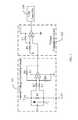
- the electronic device 1assigns power to the USB port 163 .
- the nonstandard USB device 23requires only one USB port 163 to provide power in the instant invention. Accordingly, the USB port 23 is defined as a nonstandard USB port.
- an inrush currentis generated due to a load capacitance of the USB devices. If the inrush current is not limited, the total current detection circuit 120 and the short-circuit detection circuits 131 , 132 , 133 , 134 can malfunction. Therefore, the capacitor C 1 connected to the resistor R 1 in parallel limits the inrush current. Additionally, voltage output from the total current detection circuit 120 is also approximately 5V, thus, resistance of the resistor R 1 is relatively small, such as: 0.1 ⁇ . Function of the total current detection circuit 120 is as follows.
- the voltage comparison circuit 122the voltage signal output from the amplifier A 1 received by the positive input of the comparator A 2 is less than the reference voltage, so that the comparator A 2 outputs a logic low level total current detection signal, such as about 0V, to the USB controller 140 . Accordingly, the USB controller 140 controls assignment of power to the corresponding USB port by the electronic device 1 .
Landscapes
- Engineering & Computer Science (AREA)
- Theoretical Computer Science (AREA)
- General Engineering & Computer Science (AREA)
- Physics & Mathematics (AREA)
- General Physics & Mathematics (AREA)
- Computer Hardware Design (AREA)
- Power Sources (AREA)
Abstract
Description
Claims (12)
Applications Claiming Priority (3)
| Application Number | Priority Date | Filing Date | Title |
|---|---|---|---|
| CN200910304775.7 | 2009-07-24 | ||
| CN2009103047757ACN101963835B (en) | 2009-07-24 | 2009-07-24 | Electronic equipment and method for dynamically allocating USB port power |
| CN200910304775 | 2009-07-24 |
Publications (2)
| Publication Number | Publication Date |
|---|---|
| US20110018344A1 US20110018344A1 (en) | 2011-01-27 |
| US8218279B2true US8218279B2 (en) | 2012-07-10 |
Family
ID=43496635
Family Applications (1)
| Application Number | Title | Priority Date | Filing Date |
|---|---|---|---|
| US12/613,666Expired - Fee RelatedUS8218279B2 (en) | 2009-07-24 | 2009-11-06 | Electronic device and method for dynamic USB power assignment |
Country Status (2)
| Country | Link |
|---|---|
| US (1) | US8218279B2 (en) |
| CN (1) | CN101963835B (en) |
Cited By (26)
| Publication number | Priority date | Publication date | Assignee | Title |
|---|---|---|---|---|
| US20110278954A1 (en)* | 2010-05-11 | 2011-11-17 | Getac Technology Corporation | Electronic apparatus and method for conditionally power supplying |
| US20130134801A1 (en)* | 2011-11-30 | 2013-05-30 | Novatek Microelectronics Corp. | Power supply circuit for antenna, antenna control system, and digital communication device |
| EP2728439A1 (en) | 2012-10-31 | 2014-05-07 | Thomson Licensing | Device and method for electric power management of a plurality of peripheral interfaces |
| US20140359318A1 (en)* | 2012-04-27 | 2014-12-04 | Hewlett-Packarddevelopment Company, L.P. | Power adapters |
| US10976798B2 (en) | 2016-11-30 | 2021-04-13 | Trane International Inc. | Automated peripheral power management |
| TWI777624B (en)* | 2020-06-26 | 2022-09-11 | 加拿大商萬國半導體國際有限合夥公司 | Method of path short detection in port controller power and system thereof |
| US11712280B2 (en) | 2018-09-07 | 2023-08-01 | Cilag Gmbh International | Passive header module for a modular energy system |
| US11743665B2 (en) | 2019-03-29 | 2023-08-29 | Cilag Gmbh International | Modular surgical energy system with module positional awareness sensing with time counter |
| US11804679B2 (en) | 2018-09-07 | 2023-10-31 | Cilag Gmbh International | Flexible hand-switch circuit |
| US11857252B2 (en) | 2021-03-30 | 2024-01-02 | Cilag Gmbh International | Bezel with light blocking features for modular energy system |
| US11923084B2 (en) | 2018-09-07 | 2024-03-05 | Cilag Gmbh International | First and second communication protocol arrangement for driving primary and secondary devices through a single port |
| US11950860B2 (en) | 2021-03-30 | 2024-04-09 | Cilag Gmbh International | User interface mitigation techniques for modular energy systems |
| US11963727B2 (en) | 2021-03-30 | 2024-04-23 | Cilag Gmbh International | Method for system architecture for modular energy system |
| US11968776B2 (en) | 2021-03-30 | 2024-04-23 | Cilag Gmbh International | Method for mechanical packaging for modular energy system |
| US11978554B2 (en) | 2021-03-30 | 2024-05-07 | Cilag Gmbh International | Radio frequency identification token for wireless surgical instruments |
| USD1026010S1 (en) | 2019-09-05 | 2024-05-07 | Cilag Gmbh International | Energy module with alert screen with graphical user interface |
| US11980411B2 (en) | 2021-03-30 | 2024-05-14 | Cilag Gmbh International | Header for modular energy system |
| US12009621B2 (en) | 2018-08-20 | 2024-06-11 | Samsung Electronics Co., Ltd. | Device and method of ensuring power delivery in universal serial bus interface |
| US12004824B2 (en) | 2021-03-30 | 2024-06-11 | Cilag Gmbh International | Architecture for modular energy system |
| US12040749B2 (en) | 2021-03-30 | 2024-07-16 | Cilag Gmbh International | Modular energy system with dual amplifiers and techniques for updating parameters thereof |
| US12035956B2 (en) | 2018-09-07 | 2024-07-16 | Cilag Gmbh International | Instrument tracking arrangement based on real time clock information |
| US12079460B2 (en) | 2022-06-28 | 2024-09-03 | Cilag Gmbh International | Profiles for modular energy system |
| US12144136B2 (en) | 2018-09-07 | 2024-11-12 | Cilag Gmbh International | Modular surgical energy system with module positional awareness with digital logic |
| US12228987B2 (en) | 2021-03-30 | 2025-02-18 | Cilag Gmbh International | Method for energy delivery for modular energy system |
| US12235697B2 (en) | 2021-03-30 | 2025-02-25 | Cilag Gmbh International | Backplane connector attachment mechanism for modular energy system |
| US12369994B2 (en) | 2021-03-30 | 2025-07-29 | Cilag Gmbh International | Modular energy system with multi-energy port splitter for multiple energy devices |
Families Citing this family (42)
| Publication number | Priority date | Publication date | Assignee | Title |
|---|---|---|---|---|
| US7930043B2 (en) | 2006-09-15 | 2011-04-19 | International Business Machines Corporation | Method and system for discovery, validation and delivery of power through a universal power center |
| US9130400B2 (en) | 2009-09-24 | 2015-09-08 | Apple Inc. | Multiport power converter with load detection capabilities |
| US8954762B2 (en)* | 2010-06-08 | 2015-02-10 | International Business Machines Corporation | Peer to peer power management |
| CN102096486A (en)* | 2011-02-17 | 2011-06-15 | 惠州Tcl移动通信有限公司 | Wireless Internet mouse and power supply management method thereof |
| US20120242167A1 (en)* | 2011-03-25 | 2012-09-27 | I/O Interconnect, Ltd. | Method for Logically Disconnecting a USB Device from a Host without Mechanical Disconnection |
| US8806255B2 (en)* | 2011-08-31 | 2014-08-12 | Hewlett-Packard Development Company, L.P. | Interface connection control based on voltage at input rail |
| US9244511B2 (en)* | 2012-03-28 | 2016-01-26 | Echostar Uk Holdings Limited | Transient electrical load decoupling for a direct current power supply |
| US9323321B2 (en)* | 2013-04-12 | 2016-04-26 | Lenovo Enterprise Solutions (Singapore) Pte. Ltd. | Intelligent over-current prevention |
| CN103399251B (en)* | 2013-07-30 | 2017-05-10 | 广州视睿电子科技有限公司 | USB communication line detection device |
| US20150160674A1 (en)* | 2013-12-11 | 2015-06-11 | Microchip Technology Incorporated | Automatic Load Share Architecture For Usb Port Power |
| JP6375667B2 (en)* | 2014-03-31 | 2018-08-22 | ブラザー工業株式会社 | USB connection system, host device, connection device, and control program |
| CN106164813A (en)* | 2014-05-06 | 2016-11-23 | 密克罗奇普技术公司 | USB supply port controls |
| CN105591538B (en)* | 2014-10-21 | 2018-06-29 | 联想(北京)有限公司 | Universal serial bus power transfering device |
| CN105896640B (en)* | 2015-01-26 | 2019-12-17 | 鸿富锦精密工业(深圳)有限公司 | Mobile device and method for distributing current |
| TWI562498B (en) | 2015-01-26 | 2016-12-11 | Hon Hai Prec Ind Co Ltd | Mobile device and method of assigning current |
| CN105988962B (en)* | 2015-01-31 | 2018-10-12 | 鸿富锦精密工业(武汉)有限公司 | Overcurrent detecting system and circuit for detecting |
| CN105098931A (en)* | 2015-09-22 | 2015-11-25 | 广西职业技术学院 | Laptop battery protection circuit |
| US11068037B2 (en)* | 2016-01-21 | 2021-07-20 | Hewlett Packard Enterprise Development Lp | Device having main and backup power |
| CN106059286A (en)* | 2016-06-06 | 2016-10-26 | 河源市博康电子有限公司 | Power supply control method and device |
| CN106026006B (en)* | 2016-06-30 | 2019-07-16 | 成绎半导体技术(上海)有限公司 | A kind of USB Type-C interface female intelligent measurement and protection circuit |
| CN105954644B (en)* | 2016-06-30 | 2020-02-07 | 成绎半导体技术(上海)有限公司 | Public first intellectual detection system of USBType-C interface and protection circuit |
| EP3430492A4 (en)* | 2016-07-12 | 2019-11-20 | Hewlett-Packard Development Company, L.P. | BALANCING A CHARGE OF ELECTRICITY BETWEEN USB PORTS |
| CN106776400B (en)* | 2016-12-14 | 2023-11-07 | 南昌黑鲨科技有限公司 | Electronic equipment and circuit thereof, switching equipment and circuit thereof and signal control system |
| US10345834B2 (en)* | 2017-08-09 | 2019-07-09 | Qualcomm Incorporated | Sensing total current of distributed load circuits independent of current distribution using distributed voltage averaging |
| JP2019128761A (en)* | 2018-01-24 | 2019-08-01 | キヤノン株式会社 | Electronic device, and control method therefor and program |
| KR102692156B1 (en)* | 2018-02-21 | 2024-08-07 | 삼성전자주식회사 | An electronic apparatus and a method for controlling voltage output to an external electronic device according to voltage sensed at a signal terminal connected to the external electronic device |
| CN108279361B (en)* | 2018-04-17 | 2020-06-02 | 南昌黑鲨科技有限公司 | Test method and test circuit for charging port of intelligent terminal |
| CN108829621A (en)* | 2018-07-17 | 2018-11-16 | 天津瑞发科半导体技术有限公司 | A kind of usb expansion function device |
| CN110118911B (en)* | 2018-12-28 | 2022-02-15 | 贸联电子(昆山)有限公司 | USBC cable test circuit |
| CN109802467B (en)* | 2019-03-15 | 2024-01-16 | 宁波龙图通讯科技有限公司 | Intelligent multipoint charging circuit and charging device |
| CN111190847B (en)* | 2019-12-16 | 2023-06-13 | 深圳慧能泰半导体科技有限公司 | Power adjusting method based on USB Type-C interface circuit, circuit and electronic equipment |
| FR3104724B1 (en)* | 2019-12-17 | 2021-11-26 | Zodiac Aero Electric | Method and device for monitoring the operation of an electrical energy distribution system according to the USB PD protocol |
| CN111211608A (en)* | 2020-01-09 | 2020-05-29 | 广东小天才科技有限公司 | Charging short-circuit protection circuit and method and power adapter |
| CN111337783B (en)* | 2020-04-03 | 2025-02-14 | 深圳英集芯科技股份有限公司 | A test circuit and a test method thereof |
| CN211579860U (en) | 2020-04-03 | 2020-09-25 | 台达电子企业管理(上海)有限公司 | Power adapter |
| US11616449B2 (en) | 2020-04-03 | 2023-03-28 | Delta Electronics (Shanghai) Co., Ltd | Power adapter |
| CN113497564B (en)* | 2020-04-03 | 2023-08-18 | 台达电子企业管理(上海)有限公司 | Power adapter and control method thereof |
| CN112104237B (en)* | 2020-09-18 | 2024-09-17 | 深圳市云矽半导体有限公司 | Processing circuit with multiple power supply ports and electronic equipment |
| TWI808547B (en)* | 2020-11-26 | 2023-07-11 | 洪笙科技股份有限公司 | Enhanced power supplying device and power supplying method for intelligently adjusting output voltage |
| US20220313369A1 (en)* | 2021-03-30 | 2022-10-06 | Cilag Gmbh International | Method for intelligent instruments for modular energy system |
| JP7142262B1 (en)* | 2021-11-29 | 2022-09-27 | パナソニックIpマネジメント株式会社 | Communication control device and imaging device |
| CN114448098B (en)* | 2022-02-18 | 2023-03-14 | 艾乐德电子(南京)有限公司 | Parallel operation current summarizing system and method |
Citations (2)
| Publication number | Priority date | Publication date | Assignee | Title |
|---|---|---|---|---|
| JPH0698466A (en)* | 1991-06-21 | 1994-04-08 | Mitsubishi Electric Corp | Energization control device |
| CN1444151A (en) | 2002-03-07 | 2003-09-24 | 富士施乐株式会社 | General serial bus device |
Family Cites Families (2)
| Publication number | Priority date | Publication date | Assignee | Title |
|---|---|---|---|---|
| US6745342B1 (en)* | 1999-12-29 | 2004-06-01 | Infineon Technologies North America Corp. | Universal serial bus transceiver shortcut protection |
| TW200723632A (en)* | 2005-12-15 | 2007-06-16 | Inventec Corp | Current overload status-informing system and the method |
- 2009
- 2009-07-24CNCN2009103047757Apatent/CN101963835B/ennot_activeExpired - Fee Related
- 2009-11-06USUS12/613,666patent/US8218279B2/ennot_activeExpired - Fee Related
Patent Citations (3)
| Publication number | Priority date | Publication date | Assignee | Title |
|---|---|---|---|---|
| JPH0698466A (en)* | 1991-06-21 | 1994-04-08 | Mitsubishi Electric Corp | Energization control device |
| CN1444151A (en) | 2002-03-07 | 2003-09-24 | 富士施乐株式会社 | General serial bus device |
| US7124307B2 (en)* | 2002-03-07 | 2006-10-17 | Fuji Xerox Co., Ltd. | Detecting device abnormality by comparing a current value of current of electric power with a preset detecting current value based on a threshold value received by the device |
Cited By (40)
| Publication number | Priority date | Publication date | Assignee | Title |
|---|---|---|---|---|
| US20110278954A1 (en)* | 2010-05-11 | 2011-11-17 | Getac Technology Corporation | Electronic apparatus and method for conditionally power supplying |
| US8446049B2 (en)* | 2010-05-11 | 2013-05-21 | Getac Technology Corporation | Electronic apparatus and method for conditionally power supplying |
| US20130134801A1 (en)* | 2011-11-30 | 2013-05-30 | Novatek Microelectronics Corp. | Power supply circuit for antenna, antenna control system, and digital communication device |
| US9325054B2 (en)* | 2011-11-30 | 2016-04-26 | Novatek Microelectronics Corp. | Power supply circuit for antenna, antenna control system, and digital communication device |
| US20140359318A1 (en)* | 2012-04-27 | 2014-12-04 | Hewlett-Packarddevelopment Company, L.P. | Power adapters |
| EP2728439A1 (en) | 2012-10-31 | 2014-05-07 | Thomson Licensing | Device and method for electric power management of a plurality of peripheral interfaces |
| EP2728440A1 (en) | 2012-10-31 | 2014-05-07 | Thomson Licensing | Device and method for electric power management of a plurality of peripheral interfaces |
| EP2966541A1 (en) | 2012-10-31 | 2016-01-13 | Thomson Licensing | Device, arrangement and method for electric power management of a plurality of peripheral interfaces |
| US10976798B2 (en) | 2016-11-30 | 2021-04-13 | Trane International Inc. | Automated peripheral power management |
| US12009621B2 (en) | 2018-08-20 | 2024-06-11 | Samsung Electronics Co., Ltd. | Device and method of ensuring power delivery in universal serial bus interface |
| US11950823B2 (en) | 2018-09-07 | 2024-04-09 | Cilag Gmbh International | Regional location tracking of components of a modular energy system |
| US11931089B2 (en) | 2018-09-07 | 2024-03-19 | Cilag Gmbh International | Modular surgical energy system with module positional awareness sensing with voltage detection |
| US11998258B2 (en) | 2018-09-07 | 2024-06-04 | Cilag Gmbh International | Energy module for driving multiple energy modalities |
| US11804679B2 (en) | 2018-09-07 | 2023-10-31 | Cilag Gmbh International | Flexible hand-switch circuit |
| US12369960B2 (en) | 2018-09-07 | 2025-07-29 | Cilag Gmbh International | Method for energy distribution in a surgical modular energy system |
| US11918269B2 (en) | 2018-09-07 | 2024-03-05 | Cilag Gmbh International | Smart return pad sensing through modulation of near field communication and contact quality monitoring signals |
| US11923084B2 (en) | 2018-09-07 | 2024-03-05 | Cilag Gmbh International | First and second communication protocol arrangement for driving primary and secondary devices through a single port |
| US11712280B2 (en) | 2018-09-07 | 2023-08-01 | Cilag Gmbh International | Passive header module for a modular energy system |
| US12376896B2 (en) | 2018-09-07 | 2025-08-05 | Cilag Gmbh International | Power and communication mitigation arrangement for modular surgical energy system |
| US12239353B2 (en) | 2018-09-07 | 2025-03-04 | Cilag Gmbh International | Energy module for driving multiple energy modalities through a port |
| US12178491B2 (en) | 2018-09-07 | 2024-12-31 | Cilag Gmbh International | Control circuit for controlling an energy module output |
| US12144136B2 (en) | 2018-09-07 | 2024-11-12 | Cilag Gmbh International | Modular surgical energy system with module positional awareness with digital logic |
| US12042201B2 (en) | 2018-09-07 | 2024-07-23 | Cilag Gmbh International | Method for communicating between modules and devices in a modular surgical system |
| US12035956B2 (en) | 2018-09-07 | 2024-07-16 | Cilag Gmbh International | Instrument tracking arrangement based on real time clock information |
| US11743665B2 (en) | 2019-03-29 | 2023-08-29 | Cilag Gmbh International | Modular surgical energy system with module positional awareness sensing with time counter |
| USD1026010S1 (en) | 2019-09-05 | 2024-05-07 | Cilag Gmbh International | Energy module with alert screen with graphical user interface |
| US11646570B2 (en) | 2020-06-26 | 2023-05-09 | Alpha And Omega Semiconductor International Lp | Port controller power path short detection |
| TWI777624B (en)* | 2020-06-26 | 2022-09-11 | 加拿大商萬國半導體國際有限合夥公司 | Method of path short detection in port controller power and system thereof |
| US11963727B2 (en) | 2021-03-30 | 2024-04-23 | Cilag Gmbh International | Method for system architecture for modular energy system |
| US11980411B2 (en) | 2021-03-30 | 2024-05-14 | Cilag Gmbh International | Header for modular energy system |
| US11978554B2 (en) | 2021-03-30 | 2024-05-07 | Cilag Gmbh International | Radio frequency identification token for wireless surgical instruments |
| US11968776B2 (en) | 2021-03-30 | 2024-04-23 | Cilag Gmbh International | Method for mechanical packaging for modular energy system |
| US12004824B2 (en) | 2021-03-30 | 2024-06-11 | Cilag Gmbh International | Architecture for modular energy system |
| US12228987B2 (en) | 2021-03-30 | 2025-02-18 | Cilag Gmbh International | Method for energy delivery for modular energy system |
| US12235697B2 (en) | 2021-03-30 | 2025-02-25 | Cilag Gmbh International | Backplane connector attachment mechanism for modular energy system |
| US11950860B2 (en) | 2021-03-30 | 2024-04-09 | Cilag Gmbh International | User interface mitigation techniques for modular energy systems |
| US11857252B2 (en) | 2021-03-30 | 2024-01-02 | Cilag Gmbh International | Bezel with light blocking features for modular energy system |
| US12369994B2 (en) | 2021-03-30 | 2025-07-29 | Cilag Gmbh International | Modular energy system with multi-energy port splitter for multiple energy devices |
| US12040749B2 (en) | 2021-03-30 | 2024-07-16 | Cilag Gmbh International | Modular energy system with dual amplifiers and techniques for updating parameters thereof |
| US12079460B2 (en) | 2022-06-28 | 2024-09-03 | Cilag Gmbh International | Profiles for modular energy system |
Also Published As
| Publication number | Publication date |
|---|---|
| CN101963835A (en) | 2011-02-02 |
| CN101963835B (en) | 2013-04-24 |
| US20110018344A1 (en) | 2011-01-27 |
Similar Documents
| Publication | Publication Date | Title |
|---|---|---|
| US8218279B2 (en) | Electronic device and method for dynamic USB power assignment | |
| US4194147A (en) | Parallel connected switching regulator system | |
| US9287702B2 (en) | Universal power interface | |
| US8147138B2 (en) | Power supply circuit for motherboard | |
| EP2546724B1 (en) | Device and method for charging a master device using a detachable device | |
| US20100045117A1 (en) | Protection device for a power source and power unit using same | |
| US9772675B2 (en) | Power supply system of electronic device | |
| US7917779B2 (en) | Power control apparatus for motherboard | |
| JP2016140211A (en) | Power supply system | |
| JP4599146B2 (en) | Test device and power supply circuit | |
| US5224169A (en) | Protection arrangement for an audio output channel | |
| US7791854B2 (en) | Current limit protection apparatus and method for current limit protection | |
| CN104866052A (en) | Power supply system for electronic devices | |
| CN103376748A (en) | Electronic device | |
| US20160274613A1 (en) | Interface supply circuit | |
| US20140339921A1 (en) | Light Load Current Detection System | |
| KR20190002680A (en) | Voltage generating device and semiconductor chip | |
| US9853535B2 (en) | External power supply and system connection detection unit applied thereto | |
| TWI402668B (en) | An electronic device and method for assigning power to usb ports dynamically | |
| US20150070508A1 (en) | Output circuit and method of detecting whether load connected to connecting port and related video output circuit | |
| CN108227807B (en) | Voltage control circuit, display and voltage control method | |
| CN100421354C (en) | Method for controlling the mode of an electronic appliance | |
| JPH06113553A (en) | Ac adapter | |
| US12278473B2 (en) | Power circuit and electronic device having the same | |
| TW201528651A (en) | Charge device |
Legal Events
| Date | Code | Title | Description |
|---|---|---|---|
| AS | Assignment | Owner name:HON HAI PRECISION INDUSTRY CO., LTD., TAIWAN Free format text:ASSIGNMENT OF ASSIGNORS INTEREST;ASSIGNORS:LIAO, MING-YU;CHOU, YU-CHU;CHO, HSIAO-CHI;REEL/FRAME:023481/0216 Effective date:20091020 | |
| ZAAA | Notice of allowance and fees due | Free format text:ORIGINAL CODE: NOA | |
| ZAAB | Notice of allowance mailed | Free format text:ORIGINAL CODE: MN/=. | |
| STCF | Information on status: patent grant | Free format text:PATENTED CASE | |
| FPAY | Fee payment | Year of fee payment:4 | |
| MAFP | Maintenance fee payment | Free format text:PAYMENT OF MAINTENANCE FEE, 8TH YEAR, LARGE ENTITY (ORIGINAL EVENT CODE: M1552); ENTITY STATUS OF PATENT OWNER: LARGE ENTITY Year of fee payment:8 | |
| FEPP | Fee payment procedure | Free format text:MAINTENANCE FEE REMINDER MAILED (ORIGINAL EVENT CODE: REM.); ENTITY STATUS OF PATENT OWNER: LARGE ENTITY | |
| LAPS | Lapse for failure to pay maintenance fees | Free format text:PATENT EXPIRED FOR FAILURE TO PAY MAINTENANCE FEES (ORIGINAL EVENT CODE: EXP.); ENTITY STATUS OF PATENT OWNER: LARGE ENTITY | |
| STCH | Information on status: patent discontinuation | Free format text:PATENT EXPIRED DUE TO NONPAYMENT OF MAINTENANCE FEES UNDER 37 CFR 1.362 | |
| FP | Lapsed due to failure to pay maintenance fee | Effective date:20240710 |