US8217843B2 - Adjustment of radiation patterns utilizing a position sensor - Google Patents
Adjustment of radiation patterns utilizing a position sensorDownload PDFInfo
- Publication number
- US8217843B2 US8217843B2US12/404,127US40412709AUS8217843B2US 8217843 B2US8217843 B2US 8217843B2US 40412709 AUS40412709 AUS 40412709AUS 8217843 B2US8217843 B2US 8217843B2
- Authority
- US
- United States
- Prior art keywords
- antenna
- antenna configuration
- wireless device
- radiation pattern
- wireless
- Prior art date
- Legal status (The legal status is an assumption and is not a legal conclusion. Google has not performed a legal analysis and makes no representation as to the accuracy of the status listed.)
- Expired - Fee Related, expires
Links
Images


Classifications
- H—ELECTRICITY
- H04—ELECTRIC COMMUNICATION TECHNIQUE
- H04B—TRANSMISSION
- H04B7/00—Radio transmission systems, i.e. using radiation field
- H04B7/02—Diversity systems; Multi-antenna system, i.e. transmission or reception using multiple antennas
- H04B7/04—Diversity systems; Multi-antenna system, i.e. transmission or reception using multiple antennas using two or more spaced independent antennas
- H04B7/06—Diversity systems; Multi-antenna system, i.e. transmission or reception using multiple antennas using two or more spaced independent antennas at the transmitting station
- H04B7/0613—Diversity systems; Multi-antenna system, i.e. transmission or reception using multiple antennas using two or more spaced independent antennas at the transmitting station using simultaneous transmission
- H04B7/0615—Diversity systems; Multi-antenna system, i.e. transmission or reception using multiple antennas using two or more spaced independent antennas at the transmitting station using simultaneous transmission of weighted versions of same signal
- H04B7/0619—Diversity systems; Multi-antenna system, i.e. transmission or reception using multiple antennas using two or more spaced independent antennas at the transmitting station using simultaneous transmission of weighted versions of same signal using feedback from receiving side
- H—ELECTRICITY
- H01—ELECTRIC ELEMENTS
- H01Q—ANTENNAS, i.e. RADIO AERIALS
- H01Q1/00—Details of, or arrangements associated with, antennas
- H01Q1/12—Supports; Mounting means
- H01Q1/22—Supports; Mounting means by structural association with other equipment or articles
- H01Q1/2291—Supports; Mounting means by structural association with other equipment or articles used in bluetooth or WI-FI devices of Wireless Local Area Networks [WLAN]
- H—ELECTRICITY
- H01—ELECTRIC ELEMENTS
- H01Q—ANTENNAS, i.e. RADIO AERIALS
- H01Q3/00—Arrangements for changing or varying the orientation or the shape of the directional pattern of the waves radiated from an antenna or antenna system
- H01Q3/24—Arrangements for changing or varying the orientation or the shape of the directional pattern of the waves radiated from an antenna or antenna system varying the orientation by switching energy from one active radiating element to another, e.g. for beam switching
- H—ELECTRICITY
- H04—ELECTRIC COMMUNICATION TECHNIQUE
- H04B—TRANSMISSION
- H04B7/00—Radio transmission systems, i.e. using radiation field
- H04B7/02—Diversity systems; Multi-antenna system, i.e. transmission or reception using multiple antennas
- H04B7/04—Diversity systems; Multi-antenna system, i.e. transmission or reception using multiple antennas using two or more spaced independent antennas
- H04B7/06—Diversity systems; Multi-antenna system, i.e. transmission or reception using multiple antennas using two or more spaced independent antennas at the transmitting station
- H04B7/0613—Diversity systems; Multi-antenna system, i.e. transmission or reception using multiple antennas using two or more spaced independent antennas at the transmitting station using simultaneous transmission
- H04B7/0615—Diversity systems; Multi-antenna system, i.e. transmission or reception using multiple antennas using two or more spaced independent antennas at the transmitting station using simultaneous transmission of weighted versions of same signal
- H04B7/0619—Diversity systems; Multi-antenna system, i.e. transmission or reception using multiple antennas using two or more spaced independent antennas at the transmitting station using simultaneous transmission of weighted versions of same signal using feedback from receiving side
- H04B7/0621—Feedback content
- H04B7/063—Parameters other than those covered in groups H04B7/0623 - H04B7/0634, e.g. channel matrix rank or transmit mode selection
- H—ELECTRICITY
- H04—ELECTRIC COMMUNICATION TECHNIQUE
- H04L—TRANSMISSION OF DIGITAL INFORMATION, e.g. TELEGRAPHIC COMMUNICATION
- H04L1/00—Arrangements for detecting or preventing errors in the information received
- H04L1/0001—Systems modifying transmission characteristics according to link quality, e.g. power backoff
- H04L1/0002—Systems modifying transmission characteristics according to link quality, e.g. power backoff by adapting the transmission rate
- H—ELECTRICITY
- H04—ELECTRIC COMMUNICATION TECHNIQUE
- H04L—TRANSMISSION OF DIGITAL INFORMATION, e.g. TELEGRAPHIC COMMUNICATION
- H04L1/00—Arrangements for detecting or preventing errors in the information received
- H04L1/20—Arrangements for detecting or preventing errors in the information received using signal quality detector
- H—ELECTRICITY
- H04—ELECTRIC COMMUNICATION TECHNIQUE
- H04W—WIRELESS COMMUNICATION NETWORKS
- H04W24/00—Supervisory, monitoring or testing arrangements
- H04W24/02—Arrangements for optimising operational condition
- H—ELECTRICITY
- H04—ELECTRIC COMMUNICATION TECHNIQUE
- H04W—WIRELESS COMMUNICATION NETWORKS
- H04W72/00—Local resource management
- H04W72/20—Control channels or signalling for resource management
- H04W72/21—Control channels or signalling for resource management in the uplink direction of a wireless link, i.e. towards the network
- H—ELECTRICITY
- H04—ELECTRIC COMMUNICATION TECHNIQUE
- H04W—WIRELESS COMMUNICATION NETWORKS
- H04W84/00—Network topologies
- H04W84/02—Hierarchically pre-organised networks, e.g. paging networks, cellular networks, WLAN [Wireless Local Area Network] or WLL [Wireless Local Loop]
- H04W84/10—Small scale networks; Flat hierarchical networks
- H04W84/12—WLAN [Wireless Local Area Networks]
Definitions
- the present inventiongenerally relates to wireless communications and more particularly to changing radio frequency (RF) emission patterns with respect to one or more antenna arrays.
- RFradio frequency
- a wireless link in an Institute of Electrical and Electronic Engineers (IEEE) 802.11 networkmay be susceptible to interference from other access points and stations, other radio transmitting devices, and changes or disturbances in the wireless link environment between an access point and remote receiving node.
- the interferencemay degrade the wireless link thereby forcing communication at a lower data rate.
- the interferencemay, in some instances, be sufficiently strong as to disrupt the wireless link altogether.
- a data source and intermediate RF generating deviceare coupled to two or more physically separated omnidirectional antennas.
- An access pointmay select one of the omnidirectional antennas by which to maintain a wireless link. Because of the separation between the omnidirectional antennas, each antenna experiences a different signal environment and corresponding interference level with respect to the wireless link.
- a switching networkcouples the intermediate RF generating device and corresponding data source to whichever of the omnidirectional antennas experiences the least interference in the wireless link.
- a transmissionis made on each antenna configuration to determine which antenna configuration provides a more effective wireless link as might be measured by a packet error ratio.
- the trial-and-error approachis inefficient as it generally requires transmission on a “bad” antenna configuration to determine the particularities of the poor quality of that antenna configuration. Further, as the transmitting or receiving device move around, new sources of interference arise to degrade a transmission. The trial-and-error approach therefore becomes increasingly inefficient with a large number of antenna configurations and devices that may have adjustable positions.
- FIG. 1is a block diagram of a wireless device 110 in communication with one or more remote recipient device and as is generally known in the prior art. While not shown, the wireless device 110 of FIG. 1 includes an antenna apparatus, an RF transmitter and/or a receiver, which may operate using the 802.11 protocol. The wireless device 110 of FIG. 1 may be illustrative of a set-top box, a laptop computer, a television, a PCMCIA card, a remote control, a cellular telephone, a handheld gaming device, or a remote terminal.
- the wireless device 110may be a handheld device that receives input through an input mechanism configured to be used by a user. The wireless device 110 may then process the input and generates an RF signal. The generated RF signal may then be transmitted to one or more nodes 120 , 130 and 140 via wireless links. Nodes 120 - 140 may receive data, transmit data, or transmit and receive data (i.e., a data transceiver).
- Wireless device 110may also be an access point for communicating with one or more remote receiving nodes over a wireless link as might occur in an 802.11 wireless network.
- the wireless device 110may receive data from a router connected to the Internet (not shown).
- the wireless device 110may then convert and wirelessly transmit the data to one or more remote receiving nodes (e.g., receiving nodes 120 - 140 ).
- the wireless device 110 /access pointmay also receive a wireless transmission from one of the nodes 120 - 140 convert the data and allow for transmission of that data over the Internet via the aforementioned router.
- the wireless device 110may also form a part of a wireless local area network (LAN) that allows for communications among two or more of nodes 120 - 140 .
- LANwireless local area network
- node 140which may be a cellular phone with WiFi capability, may communicate with node 120 , which may be a laptop computer including a WiFi card or chip with wireless capabilities. Those communications may be routed through the wireless device 110 , which creates the wireless LAN environment.
- Wireless device 110may be placed in different positions on a wall, desk, or in conjunction with another structure.
- the radiation pattern emitted by the wireless device 110may then be based on the detected position of the device.
- a radiation pattern that extends in a horizontal manner from the wireless device 110may be desirable for a device mounted flat against a ceiling of room or on a central table-like surface.
- a radiation patternmay extend outward in a vertical manner from the wireless device 110 .
- Such an arrangementmay be desirable if one or more nodes 120 - 140 are attempting to interact with an access point (wireless device 110 ) on different floors of a building.
- Arranging wireless access points or other wireless devices in such a mannermay require the party responsible for installation of wireless device 110 to ensure that it is properly configured for a horizontal and/or vertical wireless transmission. This is especially true with prior art wireless devices and access points that tend to transmit only in one-dimension.
- the particulars of any given radiation pattern generated by a wireless devicemay be not be immediately apparent to an individual charged with creating a wireless network but otherwise lacking extensive knowledge into RF emission patterns. Further difficulties might arise with respect to intermediate arrangements of the wireless device (e.g., at a 45 degree angle).
- a device for transmitting a radiation signalincludes multiple antenna configurations, each corresponding to a radiation pattern.
- a position sensor in the devicedetects changes in position of the device.
- a processorreceives the position information from the position sensor to select an antenna configuration and physical data rate based on the position information.
- a device for transmitting a wireless signalincludes an antenna apparatus, antenna configuration selection module, and tilt sensor.
- the antenna apparatusmay be configured in a variety of configurations corresponding to various radiation patterns.
- the selection modulemay select a first configuration of the antenna apparatus and a second configuration the antenna apparatus based on a position of the wireless device as detected by the tilt sensor.
- a wireless device for transmitting a wireless signalincludes an antenna apparatus, position sensor, and antenna configuration selection module.
- Various antenna configurations, each associated with a radiation pattern,are possible with respect to the antenna apparatus.
- the position sensordetects a position of the wireless device while execution of the antenna selection modules causes selection of an antenna configuration based on the detected position of the wireless device position.
- a method for adjusting a radiation patternincludes select a first antenna configuration corresponding to a radiation pattern when a wireless device is in a first position; transmitting an RF signal using the first configuration; detecting a change in the position of the device; selecting a second antenna configuration having a second pattern; and transmitting an RF signal using the second configuration.
- FIG. 1is a block diagram of a wireless device in communication with one or more remote recipient devices and as is generally known in the prior art.
- FIG. 2is a block diagram of an exemplary wireless device transmitting an RF signal in different physical positions.
- FIG. 3is a block diagram of an exemplary wireless device, which may be configured in different physical positions like that disclosed in FIG. 2 .
- FIG. 4is a block diagram of an exemplary software layer, interface layer and hardware layer of the wireless device of FIG. 3 .
- FIG. 5is an exemplary table of transmission control data as may be utilized by the wireless device of FIG. 3 .
- FIG. 6is an exemplary method for transmitting data based on the physical position of a wireless device.
- FIG. 7illustrates an exemplary method for processing feedback at a wireless device.
- a device for a wireless RF link to a remote receiving deviceincludes an antenna apparatus with selectable antenna elements for transmitting and receiving an RF signal, a signal converter for converting between encoded signals and RF signals, a processor for controlling the signal converter and the antenna apparatus, and a position sensor.
- the position sensordetects a change in position and provides position information to the processor.
- the processorreceives the position information from the position sensor, selects an antenna configuration based on the position information, and selects a physical data rate to maximize data transmission speed.
- the processorthen provides an encoded signal to the signal converter and controls the converter and antenna apparatus to provide an RF signal through the antenna elements of the selected antenna configuration.
- the directional radiation pattern resulting from a selected antenna configurationmay extend horizontally and perpendicular.
- the wireless device positionis changed so that it resides on a side and in a horizontal position (i.e., ninety degrees from the previous position)
- the change in positionis detected and a second antenna configuration having a second radiation pattern.
- the second radiation patternmay extend through the top of the device. If no change to the antenna configuration was made in response to the changed position, the selected antenna configuration would result in a radiation pattern that extends in a vertical position (still perpendicular from the sides of the device), and thus a weaker signal in the original direction from the horizontal position.
- a device RF signalcan also be changed due to interference from other radio transmitting devices detected at the new device position, or disturbances in the wireless link between the system and the remote receiving device.
- the processormay select an antenna configuration with a resulting radiation pattern that minimizes the interference.
- the processormay select an antenna configuration corresponding to a maximum gain between the system and the remote receiving device.
- the processormay select an antenna configuration corresponding to less than maximal gain, but corresponding to reduced interference in the wireless link.
- the processormay select a physical data rate that maximizes data transmission speed, referred to herein as an effective user data rate, over the wireless link to the remote receiving device.
- FIG. 2is a block diagram of an exemplary wireless device 210 transmitting a signal while in different physical positions.
- Wireless device 210may also receive a wireless signal.
- the wireless device 210 of FIG. 2includes selectable antenna elements, a signal converter, a processor, memory, various software elements, which may be stored in memory and executable by a processor, and a position sensor.
- wireless device 210In the upright position, wireless device 210 has an antenna configuration having a horizontal radiation pattern which extends horizontally from a side of device 210 .
- wireless device 210changes position—by approximately ninety degrees from the vertical position to the horizontal position in FIG. 2 —and is placed on a side, the change of position being detected by an internal position sensor, the antenna configuration is adjusted in an according fashion and based on the current detected position or the detected change of position such that a radiation pattern is generated that extends outward and from the top of wireless device 210 thereby resulting in a second radiation pattern that extends through space in the same direction as the first radiation pattern provided by wireless device 210 .
- the wireless patternHad the wireless pattern not been adjusted from the change in physical position of wireless device 210 , the radiation pattern would in a vertical pattern, which may be of use only to a receiving device immediately above or below the wireless transmitting device 210 .
- FIG. 3is a block diagram of an exemplary wireless device 300 , which may be configured in different physical positions like that disclosed in FIG. 2 .
- Wireless device 300may be any device that can be moved and is capable of transmitting and receiving a wireless signal.
- wireless device 300may be implemented as a cellular phone, personal digital assistant, gaming controller, a lap top computer, or access point subject to being moved.
- Wireless device 300 as illustrated in FIG. 3includes processor 310 , accelerometer 315 , tilt sensor 320 , output 325 , input 330 , display 335 , memory 340 , antenna element selector 345 , signal converter 350 , antenna elements 355 , network connection 360 , and data bus 365 .
- Processor 310 of FIG. 3is coupled to a memory 340 .
- Processor 310may be representative of a microcontroller, a microprocessor, or an application-specific integrated circuit (ASIC).
- the processor 310may execute programs stored in memory 340 .
- Memory 340may also store transmission control data, which may be retrieved by the processor 310 to control selection of the antenna configuration of the antenna apparatus 355 and selection of the physical data rate of the signal converter 350 . Aspects of transmission control, antenna element selection, data rate and so forth are discussed in greater detail with respect to FIGS. 4 and 5 , below.
- Processor 310 of FIG. 3is further coupled to antenna element selector device 345 such coupling occurring via control bus 365 .
- Antenna element selector device 345is, in turn, coupled to antenna apparatus 355 to allow selection of individual or groups of antenna elements. Different combinations of selected antenna elements may result in different radiation patterns.
- Processor 310controls the antenna element selector device 345 to select a radiation pattern corresponding to a given antenna configuration of antenna apparatus 355 .
- Processor 310is also coupled to the signal converter 350 by the control bus 365 .
- Processor 310controls signal converter 350 to select a physical data rate from multiple physical data rates at which the signal converter 350 converts data bits into RF signals for transmission via the antenna apparatus 355 .
- Processor 310may receive packet data from an external network 360 .
- Received packet datais converted into data corresponding to an 802.11 wireless protocol at signal converter 350 (e.g., a radio modulator/demodulator) at the selected physical data rate.
- the converted datais transmitted as an RF transmission via the antenna apparatus 355 to a remote node over a wireless link.
- Antenna apparatus 110includes a plurality of individually selectable antenna elements (not shown) within antenna apparatus 355 .
- the antenna apparatusmay include two antenna elements, three four antenna elements, or more than four antenna elements. When selected, each of the antenna elements produces a directional radiation pattern with gain as compared to an omnidirectional antenna.
- the elements of antenna apparatus 355are each either directly coupled to an antenna element selector 345 or via an intermediate individual antenna element.
- Antenna element selector 345selectively couples one or more of the antenna elements to the signal converter 350 for transmitting a generated RF signal.
- Various embodiments of the antenna apparatus 355 and the antenna element selector device 345are further described in commonly owned U.S. Pat. Nos. 7,292,198; 7,193,562; and 7,362,280.
- Device 300may include any number of ports or interfaces, which may correspond to serial communication architectures like Universal Serial Bus (USB), RS-x, FireWire, Ethernet, SCSI, and PCI Express or parallel communication architectures such as ATA, HIPPI, IEEE-488, and PCMCIA for output devices 325 and input devices 330 .
- serial communication architectureslike Universal Serial Bus (USB), RS-x, FireWire, Ethernet, SCSI, and PCI Express or parallel communication architectures such as ATA, HIPPI, IEEE-488, and PCMCIA
- output devices 325 and input devices 330Examples of suitable output devices include speakers, printers, network interfaces, and monitors.
- Input devices 330may include or be coupled to user interfaces such as alpha-numeric keypads and keyboards, or pointing devices such as a mouse, a trackball, stylus, or cursor direction keys.
- Display system 335may include a liquid crystal display (LCD) or other suitable display device. Display system 335 receives textual and graphical information, and processes the information for output to the display device. Output 325 , input 330 , display 335 and memory 340 are coupled to processor 310 via one or more buses 365 .
- LCDliquid crystal display
- Tilt sensor 320can measure the tilting in two axes of a reference plane. Tilt sensor 320 may detect pitch and roll and look angles and may be used to detect a change of position such as angular tilt and transmit a signal indicating the position or tilt to processor 310 . Processor 310 may then process the signal to select an antenna configuration that provides the best coverage signal for the current position of the wireless device 300 . Tilt sensor 320 may be implemented as one or more horizontal, vertical, analog, or digital tilt sensors, and may be implemented as an electrolytic, mercury, gas bubble liquid, pendulum, or other type of tilt sensor.
- tilt sensor 320may be an electrolytic tilt sensor, which produces an electric signal to indicate how much a structure is leaning in reference to gravity.
- Tilt sensor 320may, in the context of a wireless access point, detect whether device 300 is positioned in a horizontal position (e.g., flat against a ceiling), in a vertical position (e.g., against a wall), or in some other position.
- a tilt sensormay also determinate, in the case of a mobile phone, determine whether the wireless device 300 is positioned upright or is laying relatively flat on a surface such as a table and generate a signal used in the selection of an antenna configuration at antenna apparatus 355 and corresponding radiation pattern.
- Accelerometer 315can measure acceleration forces experienced by wireless device 300 . These forces may be static such as constant force of gravity pulling at the device, or dynamic such as a force caused by moving or vibrating device 300 . When an acceleration force is detected by accelerometer 315 , accelerometer 315 can provide a signal to processor 310 to report the detected acceleration. Processor 310 can process the accelerometer signal to aid in the selection of an antenna configuration at antenna apparatus 355 that provides a suitable radiation pattern based on any acceleration or change in the position of device 300 . In some cases, though tilt sensor may not detect a changed position of device 300 , accelerometer 315 may detect acceleration in device 300 . In such circumstances, processor 310 may probe for an antenna configuration that provides the best radiation pattern in response to the accelerometer signal.
- Wireless device 300may also include a global positioning system (GPS) device.
- GPSglobal positioning system
- the GPS devicemay be coupled to processor 310 and able to receive and process signals received from GPS satellites or other signal sources.
- the location of wireless device 300may be determined by estimating the time for the GPS device to receive a signal from source satellites or other signal sources. The determined location can be provided to processor 310 as a signal by the GPS device.
- Processor 310can process the GPS device signal to aid in the selection of an antenna configuration at antenna apparatus 355 that provides a suitable radiation pattern based on any current position or change in the position of device 300 .
- Memory 340may include programs and instructions for execution by processor 310 . When executed, the programs may select antenna configurations based on a detected position, change in position, or other position information provided by accelerometer 315 and/or tilt sensor 320 . Selecting an antenna configuration may include creating a table having transmission parameter control data for each remote node. The table may include link quality metrics for each antenna configuration. Some examples of link quality metrics are a success ratio, an effective user data rate, a received signal strength indicator (RSSI), and error vector magnitude (EVM).
- RSSIreceived signal strength indicator
- EVMerror vector magnitude
- the success ratiocan be calculated as a number of data packets received by the particular remote receiving node 130 divided by a number of data packets transmitted to the remote receiving node 130 .
- the success ratiomay be dependent on the physical data rate used to transmit on the antenna configuration.
- the tablemay be sorted by the success ratio, for example, so that highly successful antenna configurations may be preferably selected.
- a success ratiomay also be calculated in a similar fashion with respect to data successfully received from a transmitting node.
- FIG. 4illustrates a block diagram of an exemplary software layer 410 , interface layer 460 , and hardware layer 470 of the wireless device of FIG. 3 .
- the software layer 410 and the interface layer 460include instructions executed by processor 310 .
- Hardware layer 470includes hardware elements of the device 100 described with respect to FIG. 3 , such as the processor 310 , antenna element selector 345 , signal converter 350 , and antenna apparatus 355 . Although described as software and hardware elements, aspects of the device 300 may be implemented with any combination of software, hardware, and firmware elements.
- Software layer 410 of FIG. 4includes a transmission control selection module 430 and a feedback module 440 .
- the transmission control selection module 430 of FIG. 4includes an antenna configuration selection module 415 , position sensor module 420 , and probe scheduler 425 .
- the feedback module 440is communicatively coupled to database 435 , which may be integrated in the feedback module 440 .
- the hardware layer 470 of FIG. 4includes a transmitter 460 and a receiver 465 .
- the transmission control selection 430is communicatively linked to feedback module 440 .
- Transmission control selection 430communicates with the interface layer 460 via link 445 .
- the feedback modulecommunicates with the interface layer 460 via link 450 .
- the interface layer 460receives packets via link 455 from software layer 410 and sends the packets to the transmitter 475 in the hardware layer 470 .
- the interface layer 460also receives packets from receiver 465 in the hardware layer 470 and sends the packets to the software layer 410 via link 445 .
- the transmission control selection 430includes software elements configured to select and communicate through the interface layer 460 the current antenna configuration and the current physical data rate based on the feedback module 440 , probe scheduler 425 , or position sensor module 420 .
- the probe scheduler 425includes software elements configured to determine for the transmission control selection 430 an unused antenna configuration and an unused physical data rate based on predetermined criteria.
- the predetermined criteriais determining an unused antenna configuration after the interface layer 460 indicates as received five consecutive packets.
- the feedback module 440includes software elements configured to update link quality metrics for each antenna configuration and each physical data rate based on feedback from the interface layer 460 .
- the feedback module 440is configured to maintain the link quality metrics in the database 435 .
- the position sensor module 420includes software elements that receive and process signals from accelerometer 315 and tilt sensor 320 ( FIG. 3 ).
- the processingmay include determining whether to initiate selection of a new antenna configuration based on the signals received by position sensor module 420 .
- the operation of the software layer 410 , the interface layer 460 , and the hardware layer 470are described below with respect to FIG. 6 and FIG. 7 .
- transmission control selection 430may select, for example, an antenna configuration for the antenna apparatus 355 that minimizes interference for communicating over the wireless link to the remote receiving node 130 based on feedback (i.e., direct or indirect) from the receiving node.
- the interface layer 460indicates whether the remote receiving node received transmitted packets on a particular antenna configuration and physical data rate.
- transmission selection control 410may select another antenna configuration for communicating over the wireless link to the remote receiving node 130 based on the feedback, thereby changing the radiation pattern of the antenna apparatus 355 to minimize interference in the wireless link.
- the transmission control selection 430may select the appropriate antenna configuration corresponding to a maximum gain for a wireless links between the device 300 and a remote receiving node 130 .
- transmission control selection 430may select the antenna configuration corresponding to less than maximal gain, but corresponding to reduced interference for the particular position of the device.
- a further advantageis that transmission control selection 430 may select the physical data rate that provides the maximum effective user data rate at the remote receiving node 130 .
- FIG. 5illustrates an exemplary table 500 of transmission control data as may be utilized by the wireless device of FIG. 3 .
- the table 500 of transmission control datamay be contained in database 435 and accessed by execution of the various software elements of feedback module 440 .
- Table 500includes columns of device position, antenna configuration, attempted transmissions, successful transmissions, success ratio and RSSI.
- the rows of the table 500correspond to the multiple antenna configurations of the antenna apparatus 355 .
- a table of transmission control data for the antenna apparatus 355 having four selectable antenna elements ⁇ A, B, C, D ⁇would have fifteen possible antenna configurations comprising the set ⁇ A
- the table 500may be kept in the database 435 of FIG. 4 for each of the remote receiving nodes 120 - 140 .
- Each of the remote receiving nodes 120 - 140may require different antenna configurations and/or physical data rates for optimal performance of each of the wireless links between the device and remote receiving nodes 120 - 140 , therefore multiple table 500 s may be kept. For example, if five remote receiving nodes were associated with the device 100 , the processor 320 would maintain a separate table 500 for each of the five remote receiving nodes. For ease of discussion, only a single table 500 will be discussed.
- the table 500identifies, for each of several positions for each antenna configuration, a number of attempted transmissions and a number of successful transmissions.
- Feedback module 440updates the number of attempted transmissions for the current antenna configuration after interface layer 460 indicates a packet has transmitted to a remote receiving node.
- the feedback module 440updates the number of successful transmissions after the interface layer 460 indicates the packet is received by the remote receiving node.
- the feedback module 440may update the number of attempted transmissions after the interface layer 460 indicates whether the remote receiving node received the packet.
- the number of device positions for which transmission control data can be collectedcan vary based on device resources, designer preference, and other factors. For example, device positions can be associated with pre-arranged ninety degree intervals, such as flat up, vertical facing up, flat facing down, vertical facing down. Further, the positions can be created as the device is placed in the position. In this case, the tilt sensor 320 can provide position information to position sensor module 420 , which can in turn provide the position information to feedback module 440 to be stored in table 500 . When position information is stored in the “device position” column, transmission control data can be configured for different antenna configurations at the particular position.
- Table 500also stores a success ratio and a RSSI. Although the success ratio and the RSSI are illustrated in the table, other link quality metrics may be stored in the table 500 , such as voltage standing wave ratio (VSWR), signal quality, bit error rate, and error vector magnitude (EVM).
- the success ratioincludes a computation of the number of successful transmissions divided by the number of attempted transmissions.
- the RSSIincludes an indication of the strength of the incoming (received) signal in the receiver 480 (e.g., as measured on an 802.11 ACK packet received from the remote receiving node 120 in response to a packet transmitted to the remote receiving node 120 ).
- the RSSImay provide a better measurement than the success ratio for differentiating between antenna configurations.
- the RSSImay provide a better link quality metric for determining the current antenna configuration when each antenna configuration has small values for the number of attempted transmissions and the number of successful transmissions.
- the RSSImay provide a more precise link quality metric. If one antenna configuration has the RSSI value of 110 and the other antenna configuration has the RSSI value of 115, for example, then the antenna configuration with the stronger RSSI would potentially provide a more stable wireless link.
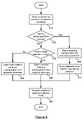
- FIG. 6is an exemplary method for transmitting data based on the physical position of a wireless device.
- Feedback module 440may initialize the number of attempted transmissions and successful transmissions in table 500 to be zero.
- the feedback module 440may determine alternative initialization values for the table 500 .
- the feedback module 440may determine initialization values for an antenna configuration that provides a substantially omnidirectional radiation pattern.
- the initialization values for the antenna configurationmay be a high value for the success ratio or the RSSI to force transmission control selection 430 to select the antenna configuration for the interface layer 460 .
- step 610packets are received for transmission using antenna elements of antenna apparatus 355 .
- the packetscan be received from over network 360 from another wireless device or a wired network, through input 330 , or with respect to data in memory 340 ( FIG. 3 ).
- the packetsmay be encoded and converted to RF format by signal converter 350 .
- the converted packetscan be provided to interface layer 460 .
- the position changemay be detected by tilt sensor 320 , accelerometer 315 , or a GPS device.
- Tilt sensor 320 in a wireless router device 300may detect that the device has been moved from a vertical position mounted to a wall to a horizontal position on a table.
- a tilt sensor within a cellular phone device 300may detect that the phone is moved from a horizontal position on a desk to a vertical position such as when a user picks up the phone to view a phone display.
- An accelerometermay detect that a gaming platform device 300 is being moved around and is undergoing dynamic acceleration forces. Either an accelerometer or a tilt sensor may detect that a laptop device 300 is moved as a user moves the device to another room. If any of tilt sensor 320 , accelerometer 315 , or GPS device detects a change, the detecting element will send a signal with position information to position sensor module 420 .
- tilt sensor 320may detect the current position of wireless device 300 without detecting a device position change at step 620 .
- the position of wireless device 300may be detected while wireless device 300 is stationary.
- tilt sensor 320can detect the wireless device position after the wireless device 300 has been stationary for a period of time or after detecting that movement of the wireless device 300 has stopped.
- Tilt sensor 320may send position information indicating the current position of the wireless device to position module 420 .
- the position informationmay indicate a level of tilt, a measure of acceleration, data regarding a current position of the device, data regarding a delta in the position of the device, GPS location data, or some other information representing motion or a position of the device 300 .
- Position sensor module 420receives the position information and sends a signal to antenna configuration selection module 415 indicating the current device position or a device position change occurred.
- An antenna configuration for the new device positionis selected at step 660 .
- the antenna configurationcan be selected based on the current device position or a change in detected device position.
- the antenna configurationis selected from the multiple antenna configurations in the table 500 .
- the transmission control selection 430selects the best ranked antenna configuration for the current position having the highest success ratio.
- the transmission control selection 430may alternatively select the antenna configuration having the highest RSSI for the current position.
- transmission control selection 430selects the current physical data rate from the multiple physical data rates provided by signal converter 120 .
- the multiple physical data ratesmay be defined as in the IEEE 802.11 specification for wireless networks, including the physical data rates such as 1 Mbps, 2 Mbps, 5.5 Mbps, and 11 Mbps for IEEE 802.11b.
- the interface layer 460sends the packet to the transmitter 460 of the hardware layer 470 .
- the transmitter 460transmits the packet on the current antenna configuration at the current physical data rate over the wireless link to a particular remote receiving node.
- probe scheduler 425 of transmission control selection 430determines whether to probe another antenna configuration at step 630 .
- Another antenna configurationcan be probed if the number of packets transmitted using the current antenna configuration satisfies a threshold number of packets, for example five packets.
- transmission control selection 430selects the current antenna configuration for antenna apparatus 355 from the multiple antenna configurations in the table 500 in step 650 .
- transmission control selection 430may select the listed antenna configuration having the highest success ratio.
- transmission control selection 430may select the antenna configuration having the highest RSSI.
- Transmission control selection 430can also select the current physical data rate from the multiple physical data rates provided by the signal converter 120 .
- the multiple physical data ratesmay be defined as in the IEEE 802.11 specification.
- the interface layer 460sends the packet to the transmitter 460 of the hardware layer 470 .
- the transmitter 460transmits the packet on the current antenna configuration at the current physical data rate over a wireless link to a particular remote receiving node (e.g., the remote receiving node 120 ).
- retransmission of the packetmay be a priority if the transmitted packet is not confirmed as received by the remote receiving node 120 .
- the need for retransmissionmay indicate problems in the wireless link between the transmitting device and the remote receiving node.
- transmission control selection 430attempts to determine the antenna configuration for retransmission and the physical data rate for retransmission that is most likely to be successful.
- the transmission control selection 430selects an antenna configuration for retransmission. In some embodiments, the transmission control selection 430 selects the next lower ranked antenna configuration in the table 500 . Transmission control selection 430 may also select a physical data rate for retransmission.
- the transmitter 460then transmits the packet in step 680 .
- transmission control selection 430selects the same current antenna configuration, but incrementally lowers the physical data rate at which the packet is retransmitted to the remote receiving node 120 .
- the lower physical data rateprovides the remote receiving node 120 more time to obtain a successful reception of the packet.
- transmission control selection 430alternates between selecting the next antenna configuration based on the success ratio and the RSSI.
- transmission control selection 430selects the next lower ranked antenna configuration based on the success ratio. If the interface layer 460 determines that the remote receiving node 120 did not indicate reception of the packet, interface layer 460 will retransmit the packet, and transmission control selection 430 will select the next lower ranked antenna configuration based on the RSSI. For each subsequent retransmission to the remote receiving node 120 , transmission control selection 430 alternates between selecting antenna configurations based on the success ratio and the RSSI.
- transmission control selection 430may determine to perform a probe of unused antenna configurations.
- Probingis the temporary changing of the current antenna configuration to one of the unused antenna configurations for transmission of a packet.
- the unused antenna configurationis any antenna configuration that is not the current antenna configuration.
- Probingallows the feedback module 440 to update the values of the table 500 for the unused antenna configurations. Probing consciously and temporarily changes the current antenna configuration to ensure that the database 435 is not stale. Additionally, probing allows the device 100 to anticipate changes in the wireless link.
- transmission control selection 430 in step 640selects an unused antenna configuration. Transmitting on the unused antenna configuration may result in a higher ranked success ratio than the current antenna configuration. Further, transmission control selection 430 may probe an unused physical data rate. In step 680 , the transmitter 460 transmits the probe packet to the remote receiving node 120 .
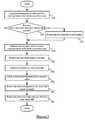
- FIG. 7illustrates an exemplary method for processing feedback at a wireless device.
- the methodbegins in step 705 after transmission of the packet, as described with respect to FIG. 6 .
- the feedback module 440increments the number of attempted transmissions 520 for the current antenna configuration.
- FIG. 7illustrates an exemplary method for processing feedback at a wireless device.
- the interface layer 460determines whether the remote receiving node 120 indicated reception of the transmitted packet. If the remote receiving node 120 indicated reception of the packet, the feedback module 440 increments the number of successful transmissions 530 for the current antenna configuration. In some embodiments, whether the remote receiving node 120 indicated reception of the packet or not, the feedback module 440 computes the success ratio for each antenna configuration.
- feedback module 440determines a variety of link quality metrics which allow the transmission control selection 430 to select an antenna configuration.
- the feedback module 440may determine the RSSI for each antenna configuration 510 for the remote receiving node 120 .
- the feedback module 440may determine the effective user data rate for each physical data rate of each antenna configuration.
- the feedback module 440ranks each of the antenna configurations by the success ratio for each configuration and device position pair.
- the feedback module 440may also rank the antenna configurations by the RSSI.
- feedback module 440may rank each physical data rate of each antenna configuration for the remote receiving node 120 by the effective user data rate. This enables the transmission control selection 430 to select a physical data rate that may have a higher effective user data rate than the current physical data rate.
Landscapes
- Engineering & Computer Science (AREA)
- Computer Networks & Wireless Communication (AREA)
- Signal Processing (AREA)
- Quality & Reliability (AREA)
- Physics & Mathematics (AREA)
- Mathematical Physics (AREA)
- Mobile Radio Communication Systems (AREA)
Abstract
Description
Claims (28)
Priority Applications (6)
| Application Number | Priority Date | Filing Date | Title |
|---|---|---|---|
| US12/404,127US8217843B2 (en) | 2009-03-13 | 2009-03-13 | Adjustment of radiation patterns utilizing a position sensor |
| EP09014989.9AEP2228868B1 (en) | 2009-03-13 | 2009-12-03 | Adjustement of radiation patterns utilizing a position sensor |
| CN201510921058.4ACN105743557A (en) | 2009-03-13 | 2009-12-29 | Adjustement of radiation patterns utilizing a position sensor |
| CN200910258884ACN101834643A (en) | 2009-03-13 | 2009-12-29 | Adjustment of Radiation Patterns Using Position Sensors |
| US13/485,012US8723741B2 (en) | 2009-03-13 | 2012-05-31 | Adjustment of radiation patterns utilizing a position sensor |
| US14/275,887US20140334322A1 (en) | 2009-03-13 | 2014-05-13 | Adjustment of radiation patterns utilizing a position sensor |
Applications Claiming Priority (1)
| Application Number | Priority Date | Filing Date | Title |
|---|---|---|---|
| US12/404,127US8217843B2 (en) | 2009-03-13 | 2009-03-13 | Adjustment of radiation patterns utilizing a position sensor |
Related Child Applications (1)
| Application Number | Title | Priority Date | Filing Date |
|---|---|---|---|
| US13/485,012ContinuationUS8723741B2 (en) | 2009-03-13 | 2012-05-31 | Adjustment of radiation patterns utilizing a position sensor |
Publications (2)
| Publication Number | Publication Date |
|---|---|
| US20100231473A1 US20100231473A1 (en) | 2010-09-16 |
| US8217843B2true US8217843B2 (en) | 2012-07-10 |
Family
ID=42224160
Family Applications (3)
| Application Number | Title | Priority Date | Filing Date |
|---|---|---|---|
| US12/404,127Expired - Fee RelatedUS8217843B2 (en) | 2009-03-13 | 2009-03-13 | Adjustment of radiation patterns utilizing a position sensor |
| US13/485,012ActiveUS8723741B2 (en) | 2009-03-13 | 2012-05-31 | Adjustment of radiation patterns utilizing a position sensor |
| US14/275,887AbandonedUS20140334322A1 (en) | 2009-03-13 | 2014-05-13 | Adjustment of radiation patterns utilizing a position sensor |
Family Applications After (2)
| Application Number | Title | Priority Date | Filing Date |
|---|---|---|---|
| US13/485,012ActiveUS8723741B2 (en) | 2009-03-13 | 2012-05-31 | Adjustment of radiation patterns utilizing a position sensor |
| US14/275,887AbandonedUS20140334322A1 (en) | 2009-03-13 | 2014-05-13 | Adjustment of radiation patterns utilizing a position sensor |
Country Status (3)
| Country | Link |
|---|---|
| US (3) | US8217843B2 (en) |
| EP (1) | EP2228868B1 (en) |
| CN (2) | CN105743557A (en) |
Cited By (28)
| Publication number | Priority date | Publication date | Assignee | Title |
|---|---|---|---|---|
| US20100091749A1 (en)* | 2004-08-18 | 2010-04-15 | William Kish | Transmission and Reception Parameter Control |
| US20120202560A1 (en)* | 2011-02-04 | 2012-08-09 | Aliphcom | Antenna optimization dependent on user context |
| US20120238288A1 (en)* | 2011-03-16 | 2012-09-20 | Aliphcom | Apparatus and method for determining relative direction of a wireless peer device from another device |
| US8670725B2 (en) | 2006-08-18 | 2014-03-11 | Ruckus Wireless, Inc. | Closed-loop automatic channel selection |
| US8686905B2 (en) | 2007-01-08 | 2014-04-01 | Ruckus Wireless, Inc. | Pattern shaping of RF emission patterns |
| US8704720B2 (en) | 2005-06-24 | 2014-04-22 | Ruckus Wireless, Inc. | Coverage antenna apparatus with selectable horizontal and vertical polarization elements |
| US8723741B2 (en) | 2009-03-13 | 2014-05-13 | Ruckus Wireless, Inc. | Adjustment of radiation patterns utilizing a position sensor |
| US8756668B2 (en) | 2012-02-09 | 2014-06-17 | Ruckus Wireless, Inc. | Dynamic PSK for hotspots |
| US8792414B2 (en) | 2005-07-26 | 2014-07-29 | Ruckus Wireless, Inc. | Coverage enhancement using dynamic antennas |
| US20150043325A1 (en)* | 2012-03-08 | 2015-02-12 | Yamaha Corporation | Wireless Terminal Device, Measurement Control Method, Control Method, Measurement Control Program, and Recording Medium |
| US9019165B2 (en) | 2004-08-18 | 2015-04-28 | Ruckus Wireless, Inc. | Antenna with selectable elements for use in wireless communications |
| US9092610B2 (en) | 2012-04-04 | 2015-07-28 | Ruckus Wireless, Inc. | Key assignment for a brand |
| US9100974B2 (en) | 2012-04-12 | 2015-08-04 | Fidelity Comtech, Inc. | System for continuously improving the performance of wireless networks with mobile users |
| US9379456B2 (en) | 2004-11-22 | 2016-06-28 | Ruckus Wireless, Inc. | Antenna array |
| US9491637B2 (en) | 2013-03-15 | 2016-11-08 | Elwha Llc | Portable wireless node auxiliary relay |
| US20160329632A1 (en)* | 2013-12-31 | 2016-11-10 | The Antenna Company International N.V. | Lte/wifi wireless router |
| US9521478B2 (en) | 2013-07-03 | 2016-12-13 | Google Technology Holdings LLC | Three-piece device ear hook |
| US9602909B2 (en) | 2013-06-20 | 2017-03-21 | Google Technology Holdings LLC | Wireless communication earpiece |
| US9608862B2 (en) | 2013-03-15 | 2017-03-28 | Elwha Llc | Frequency accommodation |
| US9634403B2 (en) | 2012-02-14 | 2017-04-25 | Ruckus Wireless, Inc. | Radio frequency emission pattern shaping |
| US9645222B2 (en) | 2011-08-08 | 2017-05-09 | Trimble Navigation Limited | Apparatus for direction finding of wireless signals |
| US9648502B2 (en) | 2012-08-15 | 2017-05-09 | Trimble Navigation Limited | System for tailoring wireless coverage to a geographic area |
| US9681311B2 (en) | 2013-03-15 | 2017-06-13 | Elwha Llc | Portable wireless node local cooperation |
| US9793596B2 (en) | 2013-03-15 | 2017-10-17 | Elwha Llc | Facilitating wireless communication in conjunction with orientation position |
| US20180091202A1 (en)* | 2016-09-29 | 2018-03-29 | Intel IP Corporation | Wireless link control and recovery using positional data |
| US10186750B2 (en) | 2012-02-14 | 2019-01-22 | Arris Enterprises Llc | Radio frequency antenna array with spacing element |
| US10985458B2 (en) | 2017-09-25 | 2021-04-20 | Huawei Technologies Co., Ltd. | Antenna apparatus and terminal device |
| US12155448B2 (en) | 2021-06-16 | 2024-11-26 | Microsoft Technology Licensing, Llc | Changing an antenna pattern |
Families Citing this family (76)
| Publication number | Priority date | Publication date | Assignee | Title |
|---|---|---|---|---|
| US8085199B2 (en)* | 2008-12-13 | 2011-12-27 | Broadcom Corporation | Receiver including a matrix module to determine angular position |
| KR101515258B1 (en)* | 2010-10-07 | 2015-04-24 | 한국전자통신연구원 | Antenna for porviding radition patterns selectively and antenna composition method |
| US8831684B2 (en)* | 2010-11-22 | 2014-09-09 | Kathrein-Werke Kg | Base transceiver station with radiation beam steering and active antenna |
| US9118416B2 (en) | 2010-12-01 | 2015-08-25 | At&T Mobility Ii Llc | Configurable segmented antenna |
| TWI447403B (en)* | 2010-12-14 | 2014-08-01 | Ind Tech Res Inst | Display apparatus and method for real-time radiation pattern visualization |
| EP2482581B1 (en) | 2011-01-28 | 2014-04-30 | Swisscom AG | User-controlled method and system for modifying the radiation of a wireless device in one or more user-selected volumes |
| CN102255619A (en)* | 2011-04-22 | 2011-11-23 | 中北大学 | Radio beacon machine |
| CN102262219A (en)* | 2011-04-22 | 2011-11-30 | 中北大学 | Wireless beacon device |
| US9042556B2 (en) | 2011-07-19 | 2015-05-26 | Sonos, Inc | Shaping sound responsive to speaker orientation |
| US9160435B2 (en)* | 2011-12-13 | 2015-10-13 | Intel Corporation | Beamforming based on information from platform sensors |
| WO2013105005A1 (en)* | 2012-01-13 | 2013-07-18 | Koninklijke Philips N.V. | Wireless docking link budget optimization system |
| EP3422589B1 (en)* | 2012-02-02 | 2024-07-24 | CommScope Technologies LLC | Optimized telecommunications distribution system |
| US8868144B2 (en)* | 2012-04-16 | 2014-10-21 | Futurewei Technologies, Inc. | Smart antenna system using orientation sensors |
| WO2013173250A1 (en) | 2012-05-13 | 2013-11-21 | Invention Mine Llc | Full duplex wireless transmission with self-interference cancellation |
| US9997830B2 (en) | 2012-05-13 | 2018-06-12 | Amir Keyvan Khandani | Antenna system and method for full duplex wireless transmission with channel phase-based encryption |
| US10489723B2 (en) | 2012-05-21 | 2019-11-26 | Nokia Technologies Oy | Apparatus and method for providing for communications using distribution lists |
| US9070974B2 (en) | 2012-05-21 | 2015-06-30 | Qualcomm Incorporated | Antenna switching devices, methods, and systems for simultaneous communication |
| US9344174B2 (en) | 2012-05-21 | 2016-05-17 | Qualcomm Incorporated | Systems, apparatus, and methods for antenna selection |
| US9055404B2 (en)* | 2012-05-21 | 2015-06-09 | Nokia Technologies Oy | Apparatus and method for detecting proximate devices |
| CN102800966B (en)* | 2012-06-20 | 2014-09-03 | 浙江大学 | Wireless remote communication method between maritime buoy nodes based on beam forming technology |
| US9608324B2 (en) | 2012-07-06 | 2017-03-28 | Industrial Technology Research Institute | Antenna apparatus and method for controlling antenna array |
| JP2014053780A (en)* | 2012-09-07 | 2014-03-20 | Sony Corp | Communication device, communication control method and program |
| KR101958864B1 (en)* | 2012-09-17 | 2019-03-15 | 삼성전자 주식회사 | Antenna apparatus using liquid metal and portable terminal using the same |
| US9001872B1 (en)* | 2012-11-07 | 2015-04-07 | Aquantia Corp. | Flexible data transmission scheme adaptive to communication channel quality |
| US9466872B2 (en) | 2012-11-09 | 2016-10-11 | Futurewei Technologies, Inc. | Tunable dual loop antenna system |
| US20140134958A1 (en)* | 2012-11-09 | 2014-05-15 | Futurewei Technologies, Inc. | Dual Feed Antenna System |
| US8774855B2 (en) | 2012-11-09 | 2014-07-08 | Futurewei Technologies, Inc. | Method to estimate head relative handset location |
| US10177896B2 (en) | 2013-05-13 | 2019-01-08 | Amir Keyvan Khandani | Methods for training of full-duplex wireless systems |
| US9871544B2 (en) | 2013-05-29 | 2018-01-16 | Microsoft Technology Licensing, Llc | Specific absorption rate mitigation |
| US10893488B2 (en) | 2013-06-14 | 2021-01-12 | Microsoft Technology Licensing, Llc | Radio frequency (RF) power back-off optimization for specific absorption rate (SAR) compliance |
| CN103488188A (en)* | 2013-09-10 | 2014-01-01 | 普联技术有限公司 | Wireless router and method of adjusting wireless router signal transmission |
| CN104467911A (en)* | 2013-09-18 | 2015-03-25 | 联想(北京)有限公司 | Antenna mode adjustment method, antenna mode adjustment device and mobile terminal |
| US9236996B2 (en) | 2013-11-30 | 2016-01-12 | Amir Keyvan Khandani | Wireless full-duplex system and method using sideband test signals |
| EP2884583B1 (en)* | 2013-12-13 | 2020-09-09 | Siemens Aktiengesellschaft | Beam forming for industrial system |
| US9563316B2 (en) | 2014-01-10 | 2017-02-07 | Microsoft Technology Licensing, Llc | Radiofrequency-wave-transparent capacitive sensor pad |
| US9813997B2 (en) | 2014-01-10 | 2017-11-07 | Microsoft Technology Licensing, Llc | Antenna coupling for sensing and dynamic transmission |
| US10044095B2 (en) | 2014-01-10 | 2018-08-07 | Microsoft Technology Licensing, Llc | Radiating structure with integrated proximity sensing |
| US9820311B2 (en) | 2014-01-30 | 2017-11-14 | Amir Keyvan Khandani | Adapter and associated method for full-duplex wireless communication |
| US9769769B2 (en) | 2014-06-30 | 2017-09-19 | Microsoft Technology Licensing, Llc | Detecting proximity using antenna feedback |
| US9785174B2 (en) | 2014-10-03 | 2017-10-10 | Microsoft Technology Licensing, Llc | Predictive transmission power control for back-off |
| US9871545B2 (en) | 2014-12-05 | 2018-01-16 | Microsoft Technology Licensing, Llc | Selective specific absorption rate adjustment |
| US10615499B2 (en) | 2015-01-14 | 2020-04-07 | Skywave Mobile Communications Inc. | Dual role antenna assembly |
| CN105846866A (en)* | 2015-01-30 | 2016-08-10 | 桂花网科技有限公司 | Bluetooth transparent repeater |
| EP3286849B1 (en)* | 2015-04-24 | 2019-04-17 | Sonos Inc. | Antenna selection |
| EP3096547A1 (en)* | 2015-05-19 | 2016-11-23 | Alcatel Lucent | Apparatuses, methods and computer programs for a first and a second base station transceiver, the first base station transceiver comprising an antenna being flexibly moveable around a mounting device for the antenna |
| EP3139537A1 (en)* | 2015-09-03 | 2017-03-08 | BAE SYSTEMS plc | Apparatus and method for communications management |
| CA2994616A1 (en) | 2015-08-13 | 2017-02-16 | Bae Systems Plc | Apparatus and method for communications management |
| EP3139538A1 (en)* | 2015-09-07 | 2017-03-08 | BAE Systems PLC | Apparatus and method for communications management |
| US10193615B2 (en) | 2015-08-13 | 2019-01-29 | Bae Systems Plc | Apparatus and method for communications management |
| EP3335333B1 (en) | 2015-08-13 | 2019-10-09 | BAE Systems PLC | Apparatus and method for communications management |
| US10278092B2 (en) | 2015-08-13 | 2019-04-30 | Bae Systems Plc | Apparatus and method for communications management |
| WO2017025741A1 (en) | 2015-08-13 | 2017-02-16 | Bae Systems Plc | Apparatus and method for communications management |
| WO2017025723A1 (en) | 2015-08-13 | 2017-02-16 | Bae Systems Plc | Apparatus and method for communications management |
| EP3335336B1 (en) | 2015-08-13 | 2025-04-16 | BAE Systems PLC | Apparatus and method for communications management |
| ES2760352T3 (en) | 2015-08-13 | 2020-05-13 | Bae Systems Plc | Apparatus and method for communications management |
| US9967884B2 (en) | 2015-11-10 | 2018-05-08 | Netgear, Inc. | Dedicated backhaul for whole home coverage |
| US10013038B2 (en) | 2016-01-05 | 2018-07-03 | Microsoft Technology Licensing, Llc | Dynamic antenna power control for multi-context device |
| KR102334098B1 (en) | 2016-04-20 | 2021-12-03 | 삼성전자주식회사 | Electronic device including display |
| US10333593B2 (en) | 2016-05-02 | 2019-06-25 | Amir Keyvan Khandani | Systems and methods of antenna design for full-duplex line of sight transmission |
| US10356681B2 (en) | 2016-09-21 | 2019-07-16 | Netgear, Inc. | Client roaming in a distributed multi-band wireless networking system |
| US10348393B2 (en)* | 2017-01-10 | 2019-07-09 | Nextivity, Inc. | Managing the beam direction of the donor antenna of a mobile repeater |
| US10461406B2 (en) | 2017-01-23 | 2019-10-29 | Microsoft Technology Licensing, Llc | Loop antenna with integrated proximity sensing |
| US10337886B2 (en) | 2017-01-23 | 2019-07-02 | Microsoft Technology Licensing, Llc | Active proximity sensor with adaptive electric field control |
| US10224974B2 (en) | 2017-03-31 | 2019-03-05 | Microsoft Technology Licensing, Llc | Proximity-independent SAR mitigation |
| US10700766B2 (en) | 2017-04-19 | 2020-06-30 | Amir Keyvan Khandani | Noise cancelling amplify-and-forward (in-band) relay with self-interference cancellation |
| US11057204B2 (en) | 2017-10-04 | 2021-07-06 | Amir Keyvan Khandani | Methods for encrypted data communications |
| US11012144B2 (en) | 2018-01-16 | 2021-05-18 | Amir Keyvan Khandani | System and methods for in-band relaying |
| US10064159B1 (en)* | 2018-01-31 | 2018-08-28 | Accton Technology Corporation | Wireless signal processing method and wireless communication device |
| KR102602370B1 (en)* | 2018-02-06 | 2023-11-16 | 삼성전자주식회사 | Apparatus and method for controlling antennas in wireless communication system |
| WO2019156458A1 (en) | 2018-02-06 | 2019-08-15 | Samsung Electronics Co., Ltd. | Apparatus and method for controlling antennas in wireless communication system |
| CN109450477B (en)* | 2018-10-31 | 2021-11-02 | 北京小米移动软件有限公司 | Antenna structure and signal receiving method, device and electronic device of electronic device |
| EP3771111B1 (en) | 2019-07-22 | 2022-11-02 | Nokia Technologies Oy | Apparatus for transmitting and/or receiving radio frequency signals and method of operating such apparatus |
| CN112448749B (en)* | 2019-09-03 | 2022-08-05 | RealMe重庆移动通信有限公司 | Antenna radiator switching method and device, storage medium and electronic device |
| TWI715197B (en)* | 2019-09-12 | 2021-01-01 | 泓博無線通訊技術有限公司 | Embedded smart antenna module of smart tv |
| US20230089409A1 (en)* | 2020-03-05 | 2023-03-23 | Lg Electronics Inc. | Electronic device comprising antenna |
| EP3968532A1 (en)* | 2020-09-14 | 2022-03-16 | Nokia Technologies Oy | User equipment beam correspondence |
Citations (218)
| Publication number | Priority date | Publication date | Assignee | Title |
|---|---|---|---|---|
| US723188A (en) | 1900-07-16 | 1903-03-17 | Nikola Tesla | Method of signaling. |
| US1869659A (en) | 1929-10-12 | 1932-08-02 | Broertjes Willem | Method of maintaining secrecy in the transmission of wireless telegraphic messages |
| US2292387A (en) | 1941-06-10 | 1942-08-11 | Markey Hedy Kiesler | Secret communication system |
| US3488445A (en) | 1966-11-14 | 1970-01-06 | Bell Telephone Labor Inc | Orthogonal frequency multiplex data transmission system |
| US3568105A (en) | 1969-03-03 | 1971-03-02 | Itt | Microstrip phase shifter having switchable path lengths |
| US3967067A (en) | 1941-09-24 | 1976-06-29 | Bell Telephone Laboratories, Incorporated | Secret telephony |
| US3982214A (en) | 1975-10-23 | 1976-09-21 | Hughes Aircraft Company | 180° phase shifting apparatus |
| US3991273A (en) | 1943-10-04 | 1976-11-09 | Bell Telephone Laboratories, Incorporated | Speech component coded multiplex carrier wave transmission |
| US4001734A (en) | 1975-10-23 | 1977-01-04 | Hughes Aircraft Company | π-Loop phase bit apparatus |
| US4027307A (en) | 1972-12-22 | 1977-05-31 | Litchstreet Co. | Collision avoidance/proximity warning system using secondary radar |
| US4176356A (en) | 1977-06-27 | 1979-11-27 | Motorola, Inc. | Directional antenna system including pattern control |
| US4193077A (en) | 1977-10-11 | 1980-03-11 | Avnet, Inc. | Directional antenna system with end loaded crossed dipoles |
| US4253193A (en) | 1977-11-05 | 1981-02-24 | The Marconi Company Limited | Tropospheric scatter radio communication systems |
| US4305052A (en) | 1978-12-22 | 1981-12-08 | Thomson-Csf | Ultra-high-frequency diode phase shifter usable with electronically scanning antenna |
| US4513412A (en) | 1983-04-25 | 1985-04-23 | At&T Bell Laboratories | Time division adaptive retransmission technique for portable radio telephones |
| US4554554A (en) | 1983-09-02 | 1985-11-19 | The United States Of America As Represented By The Secretary Of The Navy | Quadrifilar helix antenna tuning using pin diodes |
| US4733203A (en) | 1984-03-12 | 1988-03-22 | Raytheon Company | Passive phase shifter having switchable filter paths to provide selectable phase shift |
| US4814777A (en) | 1987-07-31 | 1989-03-21 | Raytheon Company | Dual-polarization, omni-directional antenna system |
| US5063574A (en) | 1990-03-06 | 1991-11-05 | Moose Paul H | Multi-frequency differentially encoded digital communication for high data rate transmission through unequalized channels |
| US5097484A (en) | 1988-10-12 | 1992-03-17 | Sumitomo Electric Industries, Ltd. | Diversity transmission and reception method and equipment |
| US5173711A (en) | 1989-11-27 | 1992-12-22 | Kokusai Denshin Denwa Kabushiki Kaisha | Microstrip antenna for two-frequency separate-feeding type for circularly polarized waves |
| EP0534612A2 (en) | 1991-08-28 | 1993-03-31 | Motorola, Inc. | Cellular system sharing of logical channels |
| US5203010A (en) | 1990-11-13 | 1993-04-13 | Motorola, Inc. | Radio telephone system incorporating multiple time periods for communication transfer |
| US5208564A (en) | 1991-12-19 | 1993-05-04 | Hughes Aircraft Company | Electronic phase shifting circuit for use in a phased radar antenna array |
| US5220340A (en) | 1992-04-29 | 1993-06-15 | Lotfollah Shafai | Directional switched beam antenna |
| US5282222A (en) | 1992-03-31 | 1994-01-25 | Michel Fattouche | Method and apparatus for multiple access between transceivers in wireless communications using OFDM spread spectrum |
| US5291289A (en) | 1990-11-16 | 1994-03-01 | North American Philips Corporation | Method and apparatus for transmission and reception of a digital television signal using multicarrier modulation |
| US5311550A (en) | 1988-10-21 | 1994-05-10 | Thomson-Csf | Transmitter, transmission method and receiver |
| US5373548A (en) | 1991-01-04 | 1994-12-13 | Thomson Consumer Electronics, Inc. | Out-of-range warning system for cordless telephone |
| US5453752A (en) | 1991-05-03 | 1995-09-26 | Georgia Tech Research Corporation | Compact broadband microstrip antenna |
| US5507035A (en) | 1993-04-30 | 1996-04-09 | International Business Machines Corporation | Diversity transmission strategy in mobile/indoor cellula radio communications |
| US5532708A (en) | 1995-03-03 | 1996-07-02 | Motorola, Inc. | Single compact dual mode antenna |
| US5559800A (en) | 1994-01-19 | 1996-09-24 | Research In Motion Limited | Remote control of gateway functions in a wireless data communication network |
| US5754145A (en) | 1995-08-23 | 1998-05-19 | U.S. Philips Corporation | Printed antenna |
| US5767755A (en) | 1995-10-25 | 1998-06-16 | Samsung Electronics Co., Ltd. | Radio frequency power combiner |
| US5767809A (en) | 1996-03-07 | 1998-06-16 | Industrial Technology Research Institute | OMNI-directional horizontally polarized Alford loop strip antenna |
| US5786793A (en) | 1996-03-13 | 1998-07-28 | Matsushita Electric Works, Ltd. | Compact antenna for circular polarization |
| US5802312A (en) | 1994-09-27 | 1998-09-01 | Research In Motion Limited | System for transmitting data files between computers in a wireless environment utilizing a file transfer agent executing on host system |
| EP0883206A2 (en) | 1997-06-07 | 1998-12-09 | Fraunhofer-Gesellschaft Zur Förderung Der Angewandten Forschung E.V. | Transmitting/Receiving apparatus for high frequencies and usage of the apparatus |
| US5964830A (en) | 1995-08-22 | 1999-10-12 | Durrett; Charles M. | User portal device for the world wide web to communicate with a website server |
| US5990838A (en) | 1996-06-12 | 1999-11-23 | 3Com Corporation | Dual orthogonal monopole antenna system |
| US6005525A (en) | 1997-04-11 | 1999-12-21 | Nokia Mobile Phones Limited | Antenna arrangement for small-sized radio communication devices |
| US6011450A (en) | 1996-10-11 | 2000-01-04 | Nec Corporation | Semiconductor switch having plural resonance circuits therewith |
| US6031503A (en) | 1997-02-20 | 2000-02-29 | Raytheon Company | Polarization diverse antenna for portable communication devices |
| US6034638A (en) | 1993-05-27 | 2000-03-07 | Griffith University | Antennas for use in portable communications devices |
| US6052093A (en) | 1996-12-18 | 2000-04-18 | Savi Technology, Inc. | Small omni-directional, slot antenna |
| US6091364A (en) | 1996-06-28 | 2000-07-18 | Kabushiki Kaisha Toshiba | Antenna capable of tilting beams in a desired direction by a single feeder circuit, connection device therefor, coupler, and substrate laminating method |
| US6094177A (en) | 1997-11-27 | 2000-07-25 | Yamamoto; Kiyoshi | Planar radiation antenna elements and omni directional antenna using such antenna elements |
| US6097347A (en) | 1997-01-29 | 2000-08-01 | Intermec Ip Corp. | Wire antenna with stubs to optimize impedance for connecting to a circuit |
| US6104356A (en) | 1995-08-25 | 2000-08-15 | Uniden Corporation | Diversity antenna circuit |
| US6169523B1 (en) | 1999-01-13 | 2001-01-02 | George Ploussios | Electronically tuned helix radiator choke |
| WO2001013461A1 (en) | 1999-08-13 | 2001-02-22 | Rangestar Wireless, Inc. | Diversity antenna system for lan communication system |
| JP2001057560A (en) | 1999-08-18 | 2001-02-27 | Hitachi Kokusai Electric Inc | Wireless LAN system |
| EP0756381B1 (en) | 1995-07-24 | 2001-03-14 | Murata Manufacturing Co., Ltd. | High-frequency switch |
| US6266528B1 (en) | 1998-12-23 | 2001-07-24 | Arraycomm, Inc. | Performance monitor for antenna arrays |
| US6288682B1 (en) | 1996-03-14 | 2001-09-11 | Griffith University | Directional antenna assembly |
| US6292153B1 (en) | 1999-08-27 | 2001-09-18 | Fantasma Network, Inc. | Antenna comprising two wideband notch regions on one coplanar substrate |
| US6307524B1 (en) | 2000-01-18 | 2001-10-23 | Core Technology, Inc. | Yagi antenna having matching coaxial cable and driven element impedances |
| US6317599B1 (en) | 1999-05-26 | 2001-11-13 | Wireless Valley Communications, Inc. | Method and system for automated optimization of antenna positioning in 3-D |
| US6323810B1 (en) | 2001-03-06 | 2001-11-27 | Ethertronics, Inc. | Multimode grounded finger patch antenna |
| US20010046848A1 (en) | 1999-05-04 | 2001-11-29 | Kenkel Mark A. | Method and apparatus for predictably switching diversity antennas on signal dropout |
| US6326922B1 (en) | 2000-06-29 | 2001-12-04 | Worldspace Corporation | Yagi antenna coupled with a low noise amplifier on the same printed circuit board |
| US6337628B2 (en) | 1995-02-22 | 2002-01-08 | Ntp, Incorporated | Omnidirectional and directional antenna assembly |
| US6337668B1 (en) | 1999-03-05 | 2002-01-08 | Matsushita Electric Industrial Co., Ltd. | Antenna apparatus |
| US6345043B1 (en) | 1998-07-06 | 2002-02-05 | National Datacomm Corporation | Access scheme for a wireless LAN station to connect an access point |
| US6356242B1 (en) | 2000-01-27 | 2002-03-12 | George Ploussios | Crossed bent monopole doublets |
| US6356905B1 (en) | 1999-03-05 | 2002-03-12 | Accenture Llp | System, method and article of manufacture for mobile communication utilizing an interface support framework |
| US6356243B1 (en) | 2000-07-19 | 2002-03-12 | Logitech Europe S.A. | Three-dimensional geometric space loop antenna |
| US20020031130A1 (en) | 2000-05-30 | 2002-03-14 | Kazuaki Tsuchiya | Multicast routing method and an apparatus for routing a multicast packet |
| US6377227B1 (en) | 1999-04-28 | 2002-04-23 | Superpass Company Inc. | High efficiency feed network for antennas |
| US20020047800A1 (en) | 1998-09-21 | 2002-04-25 | Tantivy Communications, Inc. | Adaptive antenna for use in same frequency networks |
| US6392610B1 (en) | 1999-10-29 | 2002-05-21 | Allgon Ab | Antenna device for transmitting and/or receiving RF waves |
| US6404386B1 (en) | 1998-09-21 | 2002-06-11 | Tantivy Communications, Inc. | Adaptive antenna for use in same frequency networks |
| US6407719B1 (en) | 1999-07-08 | 2002-06-18 | Atr Adaptive Communications Research Laboratories | Array antenna |
| US20020080767A1 (en) | 2000-12-22 | 2002-06-27 | Ji-Woong Lee | Method of supporting small group multicast in mobile IP |
| US6414647B1 (en) | 2001-06-20 | 2002-07-02 | Massachusetts Institute Of Technology | Slender omni-directional, broad-band, high efficiency, dual-polarized slot/dipole antenna element |
| US20020084942A1 (en) | 2001-01-03 | 2002-07-04 | Szu-Nan Tsai | Pcb dipole antenna |
| US6424311B1 (en) | 2000-12-30 | 2002-07-23 | Hon Ia Precision Ind. Co., Ltd. | Dual-fed coupled stripline PCB dipole antenna |
| USRE37802E1 (en) | 1992-03-31 | 2002-07-23 | Wi-Lan Inc. | Multicode direct sequence spread spectrum |
| US20020101377A1 (en) | 2000-12-13 | 2002-08-01 | Magis Networks, Inc. | Card-based diversity antenna structure for wireless communications |
| US20020105471A1 (en) | 2000-05-24 | 2002-08-08 | Suguru Kojima | Directional switch antenna device |
| US20020112058A1 (en) | 2000-12-01 | 2002-08-15 | Microsoft Corporation | Peer networking host framework and hosting API |
| US6442507B1 (en) | 1998-12-29 | 2002-08-27 | Wireless Communications, Inc. | System for creating a computer model and measurement database of a wireless communication network |
| US6445688B1 (en) | 2000-08-31 | 2002-09-03 | Ricochet Networks, Inc. | Method and apparatus for selecting a directional antenna in a wireless communication system |
| US6456242B1 (en) | 2001-03-05 | 2002-09-24 | Magis Networks, Inc. | Conformal box antenna |
| US20020158798A1 (en) | 2001-04-30 | 2002-10-31 | Bing Chiang | High gain planar scanned antenna array |
| US20020170064A1 (en) | 2001-05-11 | 2002-11-14 | Monroe David A. | Portable, wireless monitoring and control station for use in connection with a multi-media surveillance system having enhanced notification functions |
| US6493679B1 (en) | 1999-05-26 | 2002-12-10 | Wireless Valley Communications, Inc. | Method and system for managing a real time bill of materials |
| US6492957B2 (en) | 2000-12-18 | 2002-12-10 | Juan C. Carillo, Jr. | Close-proximity radiation detection device for determining radiation shielding device effectiveness and a method therefor |
| US6496083B1 (en) | 1997-06-03 | 2002-12-17 | Matsushita Electric Industrial Co., Ltd. | Diode compensation circuit including two series and one parallel resonance points |
| US6498589B1 (en) | 1999-03-18 | 2002-12-24 | Dx Antenna Company, Limited | Antenna system |
| US6499006B1 (en) | 1999-07-14 | 2002-12-24 | Wireless Valley Communications, Inc. | System for the three-dimensional display of wireless communication system performance |
| US6507321B2 (en) | 2000-05-26 | 2003-01-14 | Sony International (Europe) Gmbh | V-slot antenna for circular polarization |
| US20030026240A1 (en) | 2001-07-23 | 2003-02-06 | Eyuboglu M. Vedat | Broadcasting and multicasting in wireless communication |
| US20030030588A1 (en) | 2001-08-10 | 2003-02-13 | Music Sciences, Inc. | Antenna system |
| US20030038698A1 (en) | 2001-08-24 | 2003-02-27 | Sos From The Earth Inc. & Sun Tech., Co., Ltd. | Card-type apparatus and method for generating zero magnetic field |
| US6531985B1 (en) | 2000-08-14 | 2003-03-11 | 3Com Corporation | Integrated laptop antenna using two or more antennas |
| US20030063591A1 (en) | 2001-10-03 | 2003-04-03 | Leung Nikolai K.N. | Method and apparatus for data packet transport in a wireless communication system using an internet protocol |
| US6583765B1 (en) | 2001-12-21 | 2003-06-24 | Motorola, Inc. | Slot antenna having independent antenna elements and associated circuitry |
| US6586786B2 (en) | 2000-12-27 | 2003-07-01 | Matsushita Electric Industrial Co., Ltd. | High frequency switch and mobile communication equipment |
| US20030122714A1 (en) | 2001-11-16 | 2003-07-03 | Galtronics Ltd. | Variable gain and variable beamwidth antenna (the hinged antenna) |
| US6606059B1 (en) | 2000-08-28 | 2003-08-12 | Intel Corporation | Antenna for nomadic wireless modems |
| US6611230B2 (en) | 2000-12-11 | 2003-08-26 | Harris Corporation | Phased array antenna having phase shifters with laterally spaced phase shift bodies |
| US20030169330A1 (en) | 2001-10-24 | 2003-09-11 | Microsoft Corporation | Network conference recording system and method including post-conference processing |
| US6625454B1 (en) | 2000-08-04 | 2003-09-23 | Wireless Valley Communications, Inc. | Method and system for designing or deploying a communications network which considers frequency dependent effects |
| US20030184490A1 (en) | 2002-03-26 | 2003-10-02 | Raiman Clifford E. | Sectorized omnidirectional antenna |
| US20030189521A1 (en) | 2002-04-05 | 2003-10-09 | Atsushi Yamamoto | Directivity controllable antenna and antenna unit using the same |
| US20030189514A1 (en) | 2001-09-06 | 2003-10-09 | Kentaro Miyano | Array antenna apparatus |
| US20030189523A1 (en) | 2002-04-09 | 2003-10-09 | Filtronic Lk Oy | Antenna with variable directional pattern |
| US6633206B1 (en) | 1999-01-27 | 2003-10-14 | Murata Manufacturing Co., Ltd. | High-frequency switch |
| US6642889B1 (en) | 2002-05-03 | 2003-11-04 | Raytheon Company | Asymmetric-element reflect array antenna |
| US20030210207A1 (en) | 2002-02-08 | 2003-11-13 | Seong-Youp Suh | Planar wideband antennas |
| US20030227414A1 (en) | 2002-03-04 | 2003-12-11 | Saliga Stephen V. | Diversity antenna for UNII access point |
| US20040014432A1 (en) | 2000-03-23 | 2004-01-22 | U.S. Philips Corporation | Antenna diversity arrangement |
| US20040017860A1 (en) | 2002-07-29 | 2004-01-29 | Jung-Tao Liu | Multiple antenna system for varying transmission streams |
| US20040017310A1 (en) | 2002-07-24 | 2004-01-29 | Sarah Vargas-Hurlston | Position optimized wireless communication |
| US20040027291A1 (en) | 2002-05-24 | 2004-02-12 | Xin Zhang | Planar antenna and array antenna |
| US20040027304A1 (en) | 2001-04-30 | 2004-02-12 | Bing Chiang | High gain antenna for wireless applications |
| US20040032378A1 (en) | 2001-10-31 | 2004-02-19 | Vladimir Volman | Broadband starfish antenna and array thereof |
| US20040036654A1 (en) | 2002-08-21 | 2004-02-26 | Steve Hsieh | Antenna assembly for circuit board |
| US20040036651A1 (en) | 2002-06-05 | 2004-02-26 | Takeshi Toda | Adaptive antenna unit and terminal equipment |
| US6701522B1 (en) | 2000-04-07 | 2004-03-02 | Danger, Inc. | Apparatus and method for portal device authentication |
| US20040041732A1 (en) | 2001-10-03 | 2004-03-04 | Masayoshi Aikawa | Multielement planar antenna |
| US20040048593A1 (en) | 2000-12-21 | 2004-03-11 | Hiroyasu Sano | Adaptive antenna receiver |
| US20040058690A1 (en) | 2000-11-20 | 2004-03-25 | Achim Ratzel | Antenna system |
| US20040061653A1 (en) | 2002-09-26 | 2004-04-01 | Andrew Corporation | Dynamically variable beamwidth and variable azimuth scanning antenna |
| US20040070543A1 (en) | 2002-10-15 | 2004-04-15 | Kabushiki Kaisha Toshiba | Antenna structure for electronic device with wireless communication unit |
| US6724346B2 (en) | 2001-05-23 | 2004-04-20 | Thomson Licensing S.A. | Device for receiving/transmitting electromagnetic waves with omnidirectional radiation |
| US6725281B1 (en) | 1999-06-11 | 2004-04-20 | Microsoft Corporation | Synchronization of controlled device state using state table and eventing in data-driven remote device control model |
| US20040080455A1 (en) | 2002-10-23 | 2004-04-29 | Lee Choon Sae | Microstrip array antenna |
| US20040095278A1 (en) | 2001-12-28 | 2004-05-20 | Hideki Kanemoto | Multi-antenna apparatus multi-antenna reception method, and multi-antenna transmission method |
| US6741219B2 (en) | 2001-07-25 | 2004-05-25 | Atheros Communications, Inc. | Parallel-feed planar high-frequency antenna |
| US6747605B2 (en) | 2001-05-07 | 2004-06-08 | Atheros Communications, Inc. | Planar high-frequency antenna |
| US20040114535A1 (en) | 2002-09-30 | 2004-06-17 | Tantivy Communications, Inc. | Method and apparatus for antenna steering for WLAN |
| US6753814B2 (en) | 2002-06-27 | 2004-06-22 | Harris Corporation | Dipole arrangements using dielectric substrates of meta-materials |
| US20040125777A1 (en) | 2001-05-24 | 2004-07-01 | James Doyle | Method and apparatus for affiliating a wireless device with a wireless local area network |
| US6762723B2 (en) | 2002-11-08 | 2004-07-13 | Motorola, Inc. | Wireless communication device having multiband antenna |
| US20040145528A1 (en) | 2003-01-23 | 2004-07-29 | Kouichi Mukai | Electronic equipment and antenna mounting printed-circuit board |
| US20040160376A1 (en) | 2003-02-10 | 2004-08-19 | California Amplifier, Inc. | Compact bidirectional repeaters for wireless communication systems |
| EP1450521A2 (en) | 2003-02-19 | 2004-08-25 | Nec Corporation | Wireless communication system and method which improves reliability and throughput of communication through retransmission timeout optimization |
| US20040190477A1 (en) | 2003-03-28 | 2004-09-30 | Olson Jonathan P. | Dynamic wireless network |
| US20040203347A1 (en) | 2002-03-12 | 2004-10-14 | Hung Nguyen | Selecting a set of antennas for use in a wireless communication system |
| US6819287B2 (en) | 2002-03-15 | 2004-11-16 | Centurion Wireless Technologies, Inc. | Planar inverted-F antenna including a matching network having transmission line stubs and capacitor/inductor tank circuits |
| US20040260800A1 (en) | 1999-06-11 | 2004-12-23 | Microsoft Corporation | Dynamic self-configuration for ad hoc peer networking |
| US6839038B2 (en) | 2002-06-17 | 2005-01-04 | Lockheed Martin Corporation | Dual-band directional/omnidirectional antenna |
| US6859176B2 (en) | 2003-03-14 | 2005-02-22 | Sunwoo Communication Co., Ltd. | Dual-band omnidirectional antenna for wireless local area network |
| US6859182B2 (en) | 1999-03-18 | 2005-02-22 | Dx Antenna Company, Limited | Antenna system |
| US20050041739A1 (en) | 2001-04-28 | 2005-02-24 | Microsoft Corporation | System and process for broadcast and communication with very low bit-rate bi-level or sketch video |
| US20050042988A1 (en) | 2003-08-18 | 2005-02-24 | Alcatel | Combined open and closed loop transmission diversity system |
| US20050048934A1 (en) | 2003-08-27 | 2005-03-03 | Rawnick James J. | Shaped ground plane for dynamically reconfigurable aperture coupled antenna |
| US6876280B2 (en) | 2002-06-24 | 2005-04-05 | Murata Manufacturing Co., Ltd. | High-frequency switch, and electronic device using the same |
| US6876836B2 (en) | 2002-07-25 | 2005-04-05 | Integrated Programmable Communications, Inc. | Layout of wireless communication circuit on a printed circuit board |
| US20050074108A1 (en) | 1995-04-21 | 2005-04-07 | Dezonno Anthony J. | Method and system for establishing voice communications using a computer network |
| US6888893B2 (en) | 2001-01-05 | 2005-05-03 | Microsoft Corporation | System and process for broadcast and communication with very low bit-rate bi-level or sketch video |
| US6888504B2 (en) | 2002-02-01 | 2005-05-03 | Ipr Licensing, Inc. | Aperiodic array antenna |
| US20050097503A1 (en) | 1999-06-11 | 2005-05-05 | Microsoft Corporation | XML-based template language for devices and services |
| US6903686B2 (en) | 2002-12-17 | 2005-06-07 | Sony Ericsson Mobile Communications Ab | Multi-branch planar antennas having multiple resonant frequency bands and wireless terminals incorporating the same |
| US6906678B2 (en) | 2002-09-24 | 2005-06-14 | Gemtek Technology Co. Ltd. | Multi-frequency printed antenna |
| US20050128983A1 (en) | 2003-11-13 | 2005-06-16 | Samsung Electronics Co., Ltd. | Method for grouping transmission antennas in mobile communication system including multiple transmission/reception antennas |
| US20050138137A1 (en) | 2003-12-19 | 2005-06-23 | Microsoft Corporation | Using parameterized URLs for retrieving resource content items |
| US20050138193A1 (en) | 2003-12-19 | 2005-06-23 | Microsoft Corporation | Routing of resource information in a network |
| US6914581B1 (en) | 2001-10-31 | 2005-07-05 | Venture Partners | Focused wave antenna |
| US20050146475A1 (en) | 2003-12-31 | 2005-07-07 | Bettner Allen W. | Slot antenna configuration |
| US6924768B2 (en) | 2002-05-23 | 2005-08-02 | Realtek Semiconductor Corp. | Printed antenna structure |
| US6931429B2 (en) | 2001-04-27 | 2005-08-16 | Left Gate Holdings, Inc. | Adaptable wireless proximity networking |
| US20050180381A1 (en) | 2004-02-12 | 2005-08-18 | Retzer Michael H. | Method and apparatus for improving throughput in a wireless local area network |
| US20050188193A1 (en) | 2004-02-20 | 2005-08-25 | Microsoft Corporation | Secure network channel |
| US6941143B2 (en) | 2002-08-29 | 2005-09-06 | Thomson Licensing, S.A. | Automatic channel selection in a radio access network |
| US6943749B2 (en) | 2003-01-31 | 2005-09-13 | M&Fc Holding, Llc | Printed circuit board dipole antenna structure with impedance matching trace |
| US6950019B2 (en) | 2000-12-07 | 2005-09-27 | Raymond Bellone | Multiple-triggering alarm system by transmitters and portable receiver-buzzer |
| US6950069B2 (en) | 2002-12-13 | 2005-09-27 | International Business Machines Corporation | Integrated tri-band antenna for laptop applications |
| EP1376920B1 (en) | 2002-06-27 | 2005-10-26 | Siemens Aktiengesellschaft | Apparatus and method for data transmission in a multi-input multi-output radio communication system |
| US6961028B2 (en) | 2003-01-17 | 2005-11-01 | Lockheed Martin Corporation | Low profile dual frequency dipole antenna structure |
| US6965353B2 (en) | 2003-09-18 | 2005-11-15 | Dx Antenna Company, Limited | Multiple frequency band antenna and signal receiving system using such antenna |
| US20050267935A1 (en) | 1999-06-11 | 2005-12-01 | Microsoft Corporation | Data driven remote device control model with general programming interface-to-network messaging adaptor |
| US6973622B1 (en) | 2000-09-25 | 2005-12-06 | Wireless Valley Communications, Inc. | System and method for design, tracking, measurement, prediction and optimization of data communication networks |
| US6975834B1 (en) | 2000-10-03 | 2005-12-13 | Mineral Lassen Llc | Multi-band wireless communication device and method |
| JP2005354249A (en) | 2004-06-09 | 2005-12-22 | Matsushita Electric Ind Co Ltd | Network communication terminal |
| US6980782B1 (en) | 1999-10-29 | 2005-12-27 | Amc Centurion Ab | Antenna device and method for transmitting and receiving radio waves |
| JP2006060408A (en) | 2004-08-18 | 2006-03-02 | Nippon Telegr & Teleph Corp <Ntt> | Radio packet communication method and radio station |
| US7023909B1 (en) | 2001-02-21 | 2006-04-04 | Novatel Wireless, Inc. | Systems and methods for a wireless modem assembly |
| US7034770B2 (en) | 2002-04-23 | 2006-04-25 | Broadcom Corporation | Printed dipole antenna |
| US7034769B2 (en) | 2003-11-24 | 2006-04-25 | Sandbridge Technologies, Inc. | Modified printed dipole antennas for wireless multi-band communication systems |
| US20060094371A1 (en) | 2004-10-29 | 2006-05-04 | Colubris Networks, Inc. | Wireless access point (AP) automatic channel selection |
| US7043277B1 (en) | 2004-05-27 | 2006-05-09 | Autocell Laboratories, Inc. | Automatically populated display regions for discovered access points and stations in a user interface representing a wireless communication network deployed in a physical environment |
| US20060098607A1 (en) | 2004-10-28 | 2006-05-11 | Meshnetworks, Inc. | System and method to support multicast routing in large scale wireless mesh networks |
| US7050809B2 (en) | 2001-12-27 | 2006-05-23 | Samsung Electronics Co., Ltd. | System and method for providing concurrent data transmissions in a wireless communication network |
| US7053844B2 (en) | 2004-03-05 | 2006-05-30 | Lenovo (Singapore) Pte. Ltd. | Integrated multiband antennas for computing devices |
| US20060123455A1 (en) | 2004-12-02 | 2006-06-08 | Microsoft Corporation | Personal media channel |
| US7064717B2 (en) | 2003-12-30 | 2006-06-20 | Advanced Micro Devices, Inc. | High performance low cost monopole antenna for wireless applications |
| EP1152543B1 (en) | 1999-12-14 | 2006-06-21 | Matsushita Electric Industrial Co., Ltd. | High-frequency composite switch component |
| US7088299B2 (en) | 2003-10-28 | 2006-08-08 | Dsp Group Inc. | Multi-band antenna structure |
| GB2423191A (en) | 2005-02-02 | 2006-08-16 | Toshiba Res Europ Ltd | Antenna using orientation detector to control transmission/reception characteristics |
| US20060184693A1 (en) | 2005-02-15 | 2006-08-17 | Microsoft Corporation | Scaling and extending UPnP v1.0 device discovery using peer groups |
| US20060184660A1 (en) | 2005-02-15 | 2006-08-17 | Microsoft Corporation | Scaling UPnP v1.0 device eventing using peer groups |
| US20060225107A1 (en) | 2005-04-01 | 2006-10-05 | Microsoft Corporation | System for running applications in a resource-constrained set-top box environment |
| US20060224690A1 (en) | 2005-04-01 | 2006-10-05 | Microsoft Corporation | Strategies for transforming markup content to code-bearing content for consumption by a receiving device |
| US20060227761A1 (en) | 2005-04-07 | 2006-10-12 | Microsoft Corporation | Phone-based remote media system interaction |
| US20060239369A1 (en) | 2005-04-25 | 2006-10-26 | Benq Corporation | Methods and systems for transmission channel drlrction in wireless communication |
| EP1315311B1 (en) | 2000-08-10 | 2006-11-15 | Fujitsu Limited | Transmission diversity communication device |
| US20060262015A1 (en) | 2003-04-24 | 2006-11-23 | Amc Centurion Ab | Antenna device and portable radio communication device comprising such an antenna device |
| GB2426870A (en) | 2005-06-03 | 2006-12-06 | Lenovo | Antenna selection system for a mobile device used in various configurations |
| US7164380B2 (en) | 2001-05-22 | 2007-01-16 | Hitachi, Ltd. | Interrogator and goods management system adopting the same |
| US20070027622A1 (en) | 2005-07-01 | 2007-02-01 | Microsoft Corporation | State-sensitive navigation aid |
| US7193562B2 (en) | 2004-11-22 | 2007-03-20 | Ruckus Wireless, Inc. | Circuit board having a peripheral antenna apparatus with selectable antenna elements |
| EP1608108B1 (en) | 2004-06-17 | 2007-04-25 | Kabushiki Kaisha Toshiba | Improving channel ulilization efficiency in a wireless communication system comprising high-throughput terminals and legacy terminals |
| US20070135167A1 (en) | 2005-12-08 | 2007-06-14 | Accton Technology Corporation | Method and system for steering antenna beam |
| US7277063B2 (en) | 2003-04-02 | 2007-10-02 | Dx Antenna Company, Limited | Variable directivity antenna and variable directivity antenna system using the antennas |
| US7298228B2 (en) | 2002-05-15 | 2007-11-20 | Hrl Laboratories, Llc | Single-pole multi-throw switch having low parasitic reactance, and an antenna incorporating the same |
| US7312762B2 (en) | 2001-10-16 | 2007-12-25 | Fractus, S.A. | Loaded antenna |
| US7319432B2 (en) | 2002-03-14 | 2008-01-15 | Sony Ericsson Mobile Communications Ab | Multiband planar built-in radio antenna with inverted-L main and parasitic radiators |
| JP2008088633A (en) | 2006-09-29 | 2008-04-17 | Taiheiyo Cement Corp | Burying type form made of polymer cement mortar |
| US20080096492A1 (en)* | 2006-10-20 | 2008-04-24 | Samsung Electronics Co., Ltd. | Multi-band antenna unit of mobile terminal |
| US7609648B2 (en) | 2003-06-19 | 2009-10-27 | Ipr Licensing, Inc. | Antenna steering for an access point based upon control frames |
| US20090295648A1 (en)* | 2008-06-03 | 2009-12-03 | Dorsey John G | Antenna diversity systems for portable electronic devices |
| US7733275B2 (en)* | 2006-02-28 | 2010-06-08 | Kabushiki Kaisha Toshiba | Information apparatus and operation control method thereof |
| US7847741B2 (en)* | 2006-04-26 | 2010-12-07 | Kabushiki Kaisha Toshiba | Information processing apparatus and operation control method |
| US7916463B2 (en)* | 2008-09-12 | 2011-03-29 | Kabushiki Kaisha Toshiba | Information processing apparatus |
Family Cites Families (98)
| Publication number | Priority date | Publication date | Assignee | Title |
|---|---|---|---|---|
| US3721990A (en) | 1971-12-27 | 1973-03-20 | Rca Corp | Physically small combined loop and dipole all channel television antenna system |
| US3887925A (en) | 1973-07-31 | 1975-06-03 | Itt | Linearly polarized phased antenna array |
| US3969730A (en) | 1975-02-12 | 1976-07-13 | The United States Of America As Represented By The Secretary Of Transportation | Cross slot omnidirectional antenna |
| US4203118A (en) | 1978-04-10 | 1980-05-13 | Andrew Alford | Antenna for cross polarized waves |
| US4764773A (en) | 1985-07-30 | 1988-08-16 | Larsen Electronics, Inc. | Mobile antenna and through-the-glass impedance matched feed system |
| US4821040A (en) | 1986-12-23 | 1989-04-11 | Ball Corporation | Circular microstrip vehicular rf antenna |
| US4800393A (en) | 1987-08-03 | 1989-01-24 | General Electric Company | Microstrip fed printed dipole with an integral balun and 180 degree phase shift bit |
| US5241693A (en) | 1989-10-27 | 1993-08-31 | Motorola, Inc. | Single-block filter for antenna duplexing and antenna-switched diversity |
| US5434575A (en) | 1994-01-28 | 1995-07-18 | California Microwave, Inc. | Phased array antenna system using polarization phase shifting |
| US5479176A (en) | 1994-10-21 | 1995-12-26 | Metricom, Inc. | Multiple-element driven array antenna and phasing method |
| US5726666A (en) | 1996-04-02 | 1998-03-10 | Ems Technologies, Inc. | Omnidirectional antenna with single feedpoint |
| JPH09289413A (en)* | 1996-04-23 | 1997-11-04 | Nec Aerospace Syst Ltd | Directional controller for antenna |
| KR100213373B1 (en) | 1996-05-28 | 1999-08-02 | 이형도 | An antenna for wireless lan card |
| US5767807A (en) | 1996-06-05 | 1998-06-16 | International Business Machines Corporation | Communication system and methods utilizing a reactively controlled directive array |
| US6249216B1 (en) | 1996-08-22 | 2001-06-19 | Kenneth E. Flick | Vehicle security system including adaptor for data communications bus and related methods |
| US5936595A (en) | 1997-05-15 | 1999-08-10 | Wang Electro-Opto Corporation | Integrated antenna phase shifter |
| US6091374A (en) | 1997-09-09 | 2000-07-18 | Time Domain Corporation | Ultra-wideband magnetic antenna |
| GB9901789D0 (en) | 1998-04-22 | 1999-03-17 | Koninkl Philips Electronics Nv | Antenna diversity system |
| US6326924B1 (en) | 1998-05-19 | 2001-12-04 | Kokusai Electric Co., Ltd. | Polarization diversity antenna system for cellular telephone |
| JP2000114950A (en) | 1998-10-07 | 2000-04-21 | Murata Mfg Co Ltd | Spst switch, spdt switch and communication equipment using them |
| US6046703A (en) | 1998-11-10 | 2000-04-04 | Nutex Communication Corp. | Compact wireless transceiver board with directional printed circuit antenna |
| MXPA02001264A (en) | 1999-08-04 | 2002-07-22 | Amgen Inc | Fhm, A NOVEL MEMBER OF THE TNF LIGAND SUPERGENE FAMILY. |
| FR2803482B1 (en) | 2000-01-05 | 2002-02-15 | Diffusion Vente Internationale | ELECTRONIC KEY READER |
| US6366254B1 (en) | 2000-03-15 | 2002-04-02 | Hrl Laboratories, Llc | Planar antenna with switched beam diversity for interference reduction in a mobile environment |
| FR2808632B1 (en) | 2000-05-03 | 2002-06-28 | Mitsubishi Electric Inf Tech | TURBO-DECODING PROCESS WITH RECONCODING MISTAKEN INFORMATION AND FEEDBACK |
| US6476773B2 (en) | 2000-08-18 | 2002-11-05 | Tantivy Communications, Inc. | Printed or etched, folding, directional antenna |
| US6545643B1 (en) | 2000-09-08 | 2003-04-08 | 3Com Corporation | Extendable planar diversity antenna |
| US20020036586A1 (en) | 2000-09-22 | 2002-03-28 | Tantivy Communications, Inc. | Adaptive antenna for use in wireless communication systems |
| US7162273B1 (en) | 2000-11-10 | 2007-01-09 | Airgain, Inc. | Dynamically optimized smart antenna system |
| JP4102018B2 (en) | 2000-11-30 | 2008-06-18 | 株式会社東芝 | Wireless communication card and system |
| FI20002902A7 (en) | 2000-12-29 | 2002-06-30 | Nokia Corp | Communication device and method for connecting a transmitter and a receiver |
| EP1229647A1 (en) | 2001-01-26 | 2002-08-07 | Faurecia Industries | Capacitive actuator for a functional element, in particular of an automobile, and piece of equipment comprising such actuator |
| DE10109359C2 (en) | 2001-02-27 | 2003-01-16 | Bosch Gmbh Robert | Diversity antenna arrangement |
| JP3596477B2 (en) | 2001-02-28 | 2004-12-02 | 日本電気株式会社 | Mobile communication system and modulation / coding mode switching method used therefor |
| US6774852B2 (en) | 2001-05-10 | 2004-08-10 | Ipr Licensing, Inc. | Folding directional antenna |
| US6593891B2 (en) | 2001-10-19 | 2003-07-15 | Hitachi Cable, Ltd. | Antenna apparatus having cross-shaped slot |
| GB0125178D0 (en) | 2001-10-19 | 2001-12-12 | Koninkl Philips Electronics Nv | Method of operating a wireless communication system |
| US6879293B2 (en) | 2002-02-25 | 2005-04-12 | Tdk Corporation | Antenna device and electric appliance using the same |
| RU2231874C2 (en) | 2002-03-27 | 2004-06-27 | Общество с ограниченной ответственностью "Алгоритм" | Scanner assembly with controllable radiation pattern, transceiver and network portable computer |
| US20030214446A1 (en) | 2002-05-14 | 2003-11-20 | Imad Shehab | Diversity gain antenna |
| US6642890B1 (en) | 2002-07-19 | 2003-11-04 | Paratek Microwave Inc. | Apparatus for coupling electromagnetic signals |
| TW541762B (en) | 2002-07-24 | 2003-07-11 | Ind Tech Res Inst | Dual-band monopole antenna |
| US7046989B2 (en) | 2002-09-12 | 2006-05-16 | Broadcom Corporation | Controlling and enhancing handoff between wireless access points |
| JP2005539458A (en) | 2002-09-17 | 2005-12-22 | アイピーアール ライセンシング インコーポレイテッド | Multi-pattern antenna |
| TW569492B (en) | 2002-10-16 | 2004-01-01 | Ain Comm Technology Company Lt | Multi-band antenna |
| US7562393B2 (en) | 2002-10-21 | 2009-07-14 | Alcatel-Lucent Usa Inc. | Mobility access gateway |
| US6759990B2 (en) | 2002-11-08 | 2004-07-06 | Tyco Electronics Logistics Ag | Compact antenna with circular polarization |
| US7120405B2 (en) | 2002-11-27 | 2006-10-10 | Broadcom Corporation | Wide bandwidth transceiver |
| US7333460B2 (en) | 2003-03-25 | 2008-02-19 | Nokia Corporation | Adaptive beacon interval in WLAN |
| JP2004328717A (en) | 2003-04-11 | 2004-11-18 | Taiyo Yuden Co Ltd | Diversity antenna device |
| ATE494644T1 (en) | 2003-06-12 | 2011-01-15 | Research In Motion Ltd | MULTI-ELEMENT ANTENNA WITH FLOATING PARASITIC ANTENNA ELEMENT |
| US7675878B2 (en) | 2003-09-30 | 2010-03-09 | Motorola, Inc. | Enhanced passive scanning |
| US7444734B2 (en) | 2003-12-09 | 2008-11-04 | International Business Machines Corporation | Apparatus and methods for constructing antennas using vias as radiating elements formed in a substrate |
| US7292870B2 (en) | 2003-12-24 | 2007-11-06 | Zipit Wireless, Inc. | Instant messaging terminal adapted for Wi-Fi access points |
| US7181182B2 (en)* | 2004-03-17 | 2007-02-20 | Interdigital Technology Corporation | Method for steering a smart antenna for a WLAN using a self-monitored re-scan |
| US7763797B2 (en)* | 2004-03-22 | 2010-07-27 | Pakedge Device & Software Inc. | Ceiling-mounted wireless network access point |
| EP1756914A4 (en) | 2004-04-12 | 2008-04-02 | Airgain Inc | Switched multi-beam antenna |
| US7098863B2 (en) | 2004-04-23 | 2006-08-29 | Centurion Wireless Technologies, Inc. | Microstrip antenna |
| JP2006050267A (en) | 2004-08-04 | 2006-02-16 | Matsushita Electric Ind Co Ltd | IPsec communication method, communication control apparatus, and network camera |
| US7899497B2 (en)* | 2004-08-18 | 2011-03-01 | Ruckus Wireless, Inc. | System and method for transmission parameter control for an antenna apparatus with selectable elements |
| US7292198B2 (en) | 2004-08-18 | 2007-11-06 | Ruckus Wireless, Inc. | System and method for an omnidirectional planar antenna apparatus with selectable elements |
| US7933628B2 (en) | 2004-08-18 | 2011-04-26 | Ruckus Wireless, Inc. | Transmission and reception parameter control |
| US7362280B2 (en) | 2004-08-18 | 2008-04-22 | Ruckus Wireless, Inc. | System and method for a minimized antenna apparatus with selectable elements |
| US20060045113A1 (en)* | 2004-08-31 | 2006-03-02 | Palisca Andrea G | Method for establishing high-reliability wireless connectivity to mobile devices using multi channel radios |
| CN1934750B (en) | 2004-11-22 | 2012-07-18 | 鲁库斯无线公司 | Circuit board having a peripheral antenna apparatus with selectable antenna elements |
| US7358912B1 (en) | 2005-06-24 | 2008-04-15 | Ruckus Wireless, Inc. | Coverage antenna apparatus with selectable horizontal and vertical polarization elements |
| US7893882B2 (en) | 2007-01-08 | 2011-02-22 | Ruckus Wireless, Inc. | Pattern shaping of RF emission patterns |
| US8532304B2 (en) | 2005-04-04 | 2013-09-10 | Nokia Corporation | Administration of wireless local area networks |
| US7522569B2 (en) | 2005-06-30 | 2009-04-21 | Netgear, Inc. | Peripheral device with visual indicators to show utilization of radio component |
| USD530325S1 (en) | 2005-06-30 | 2006-10-17 | Netgear, Inc. | Peripheral device |
| US7697550B2 (en) | 2005-06-30 | 2010-04-13 | Netgear, Inc. | Peripheral device with visual indicators |
| US7782895B2 (en) | 2005-08-03 | 2010-08-24 | Nokia Corporation | Apparatus, and associated method, for allocating data for communication upon communication channels in a multiple input communication system |
| US7907971B2 (en)* | 2005-08-22 | 2011-03-15 | Airgain, Inc. | Optimized directional antenna system |
| US20070055752A1 (en) | 2005-09-08 | 2007-03-08 | Fiberlink | Dynamic network connection based on compliance |
| US7835697B2 (en) | 2006-03-14 | 2010-11-16 | Cypress Semiconductor Corporation | Frequency agile radio system and method |
| EP2025045B1 (en) | 2006-05-23 | 2011-05-11 | Intel Corporation | Chip-lens array antenna system |
| US7881474B2 (en) | 2006-07-17 | 2011-02-01 | Nortel Networks Limited | System and method for secure wireless multi-hop network formation |
| US8743778B2 (en) | 2006-09-06 | 2014-06-03 | Devicescape Software, Inc. | Systems and methods for obtaining network credentials |
| US8549588B2 (en) | 2006-09-06 | 2013-10-01 | Devicescape Software, Inc. | Systems and methods for obtaining network access |
| US7385563B2 (en) | 2006-09-11 | 2008-06-10 | Tyco Electronics Corporation | Multiple antenna array with high isolation |
| TW200816768A (en) | 2006-09-21 | 2008-04-01 | Interdigital Tech Corp | Group-wise secret key generation |
| US8060916B2 (en) | 2006-11-06 | 2011-11-15 | Symantec Corporation | System and method for website authentication using a shared secret |
| US8463238B2 (en) | 2007-06-28 | 2013-06-11 | Apple Inc. | Mobile device base station |
| US7941663B2 (en) | 2007-10-23 | 2011-05-10 | Futurewei Technologies, Inc. | Authentication of 6LoWPAN nodes using EAP-GPSK |
| EP2232892B1 (en)* | 2007-12-27 | 2016-09-14 | Nokia Technologies Oy | Maintaining the integrity of configuration information of a network of access points for use in positioning an apparatus |
| US8347355B2 (en) | 2008-01-17 | 2013-01-01 | Aerohive Networks, Inc. | Networking as a service: delivering network services using remote appliances controlled via a hosted, multi-tenant management system |
| US8250207B2 (en) | 2009-01-28 | 2012-08-21 | Headwater Partners I, Llc | Network based ambient services |
| US8351898B2 (en) | 2009-01-28 | 2013-01-08 | Headwater Partners I Llc | Verifiable device assisted service usage billing with integrated accounting, mediation accounting, and multi-account |
| US8217843B2 (en) | 2009-03-13 | 2012-07-10 | Ruckus Wireless, Inc. | Adjustment of radiation patterns utilizing a position sensor |
| JP5053424B2 (en) | 2010-07-29 | 2012-10-17 | 株式会社バッファロー | RELAY DEVICE, WIRELESS COMMUNICATION DEVICE, NETWORK SYSTEM, PROGRAM, AND METHOD |
| JP5348094B2 (en) | 2010-08-31 | 2013-11-20 | ブラザー工業株式会社 | Support device and computer program |
| US8699379B2 (en) | 2011-04-08 | 2014-04-15 | Blackberry Limited | Configuring mobile station according to type of wireless local area network (WLAN) deployment |
| US8590023B2 (en) | 2011-06-30 | 2013-11-19 | Intel Corporation | Mobile device and method for automatic connectivity, data offloading and roaming between networks |
| US9220065B2 (en) | 2012-01-16 | 2015-12-22 | Smith Micro Software, Inc. | Enabling a mobile broadband hotspot by an auxiliary radio |
| US8756668B2 (en) | 2012-02-09 | 2014-06-17 | Ruckus Wireless, Inc. | Dynamic PSK for hotspots |
| US10186750B2 (en) | 2012-02-14 | 2019-01-22 | Arris Enterprises Llc | Radio frequency antenna array with spacing element |
| US9634403B2 (en) | 2012-02-14 | 2017-04-25 | Ruckus Wireless, Inc. | Radio frequency emission pattern shaping |
| US9092610B2 (en) | 2012-04-04 | 2015-07-28 | Ruckus Wireless, Inc. | Key assignment for a brand |
- 2009
- 2009-03-13USUS12/404,127patent/US8217843B2/ennot_activeExpired - Fee Related
- 2009-12-03EPEP09014989.9Apatent/EP2228868B1/enactiveActive
- 2009-12-29CNCN201510921058.4Apatent/CN105743557A/enactivePending
- 2009-12-29CNCN200910258884Apatent/CN101834643A/enactivePending
- 2012
- 2012-05-31USUS13/485,012patent/US8723741B2/enactiveActive
- 2014
- 2014-05-13USUS14/275,887patent/US20140334322A1/ennot_activeAbandoned
Patent Citations (239)
| Publication number | Priority date | Publication date | Assignee | Title |
|---|---|---|---|---|
| US723188A (en) | 1900-07-16 | 1903-03-17 | Nikola Tesla | Method of signaling. |
| US725605A (en) | 1900-07-16 | 1903-04-14 | Nikola Tesla | System of signaling. |
| US1869659A (en) | 1929-10-12 | 1932-08-02 | Broertjes Willem | Method of maintaining secrecy in the transmission of wireless telegraphic messages |
| US2292387A (en) | 1941-06-10 | 1942-08-11 | Markey Hedy Kiesler | Secret communication system |
| US3967067A (en) | 1941-09-24 | 1976-06-29 | Bell Telephone Laboratories, Incorporated | Secret telephony |
| US3991273A (en) | 1943-10-04 | 1976-11-09 | Bell Telephone Laboratories, Incorporated | Speech component coded multiplex carrier wave transmission |
| US3488445A (en) | 1966-11-14 | 1970-01-06 | Bell Telephone Labor Inc | Orthogonal frequency multiplex data transmission system |
| US3568105A (en) | 1969-03-03 | 1971-03-02 | Itt | Microstrip phase shifter having switchable path lengths |
| US4027307A (en) | 1972-12-22 | 1977-05-31 | Litchstreet Co. | Collision avoidance/proximity warning system using secondary radar |
| US3982214A (en) | 1975-10-23 | 1976-09-21 | Hughes Aircraft Company | 180° phase shifting apparatus |
| US4001734A (en) | 1975-10-23 | 1977-01-04 | Hughes Aircraft Company | π-Loop phase bit apparatus |
| US4176356A (en) | 1977-06-27 | 1979-11-27 | Motorola, Inc. | Directional antenna system including pattern control |
| US4193077A (en) | 1977-10-11 | 1980-03-11 | Avnet, Inc. | Directional antenna system with end loaded crossed dipoles |
| US4253193A (en) | 1977-11-05 | 1981-02-24 | The Marconi Company Limited | Tropospheric scatter radio communication systems |
| US4305052A (en) | 1978-12-22 | 1981-12-08 | Thomson-Csf | Ultra-high-frequency diode phase shifter usable with electronically scanning antenna |
| US4513412A (en) | 1983-04-25 | 1985-04-23 | At&T Bell Laboratories | Time division adaptive retransmission technique for portable radio telephones |
| US4554554A (en) | 1983-09-02 | 1985-11-19 | The United States Of America As Represented By The Secretary Of The Navy | Quadrifilar helix antenna tuning using pin diodes |
| US4733203A (en) | 1984-03-12 | 1988-03-22 | Raytheon Company | Passive phase shifter having switchable filter paths to provide selectable phase shift |
| US4814777A (en) | 1987-07-31 | 1989-03-21 | Raytheon Company | Dual-polarization, omni-directional antenna system |
| US5097484A (en) | 1988-10-12 | 1992-03-17 | Sumitomo Electric Industries, Ltd. | Diversity transmission and reception method and equipment |
| US5311550A (en) | 1988-10-21 | 1994-05-10 | Thomson-Csf | Transmitter, transmission method and receiver |
| US5173711A (en) | 1989-11-27 | 1992-12-22 | Kokusai Denshin Denwa Kabushiki Kaisha | Microstrip antenna for two-frequency separate-feeding type for circularly polarized waves |
| US5063574A (en) | 1990-03-06 | 1991-11-05 | Moose Paul H | Multi-frequency differentially encoded digital communication for high data rate transmission through unequalized channels |
| US5203010A (en) | 1990-11-13 | 1993-04-13 | Motorola, Inc. | Radio telephone system incorporating multiple time periods for communication transfer |
| US5291289A (en) | 1990-11-16 | 1994-03-01 | North American Philips Corporation | Method and apparatus for transmission and reception of a digital television signal using multicarrier modulation |
| US5373548A (en) | 1991-01-04 | 1994-12-13 | Thomson Consumer Electronics, Inc. | Out-of-range warning system for cordless telephone |
| US5453752A (en) | 1991-05-03 | 1995-09-26 | Georgia Tech Research Corporation | Compact broadband microstrip antenna |
| EP0534612A2 (en) | 1991-08-28 | 1993-03-31 | Motorola, Inc. | Cellular system sharing of logical channels |
| US5208564A (en) | 1991-12-19 | 1993-05-04 | Hughes Aircraft Company | Electronic phase shifting circuit for use in a phased radar antenna array |
| US5282222A (en) | 1992-03-31 | 1994-01-25 | Michel Fattouche | Method and apparatus for multiple access between transceivers in wireless communications using OFDM spread spectrum |
| USRE37802E1 (en) | 1992-03-31 | 2002-07-23 | Wi-Lan Inc. | Multicode direct sequence spread spectrum |
| US5220340A (en) | 1992-04-29 | 1993-06-15 | Lotfollah Shafai | Directional switched beam antenna |
| US5507035A (en) | 1993-04-30 | 1996-04-09 | International Business Machines Corporation | Diversity transmission strategy in mobile/indoor cellula radio communications |
| US6034638A (en) | 1993-05-27 | 2000-03-07 | Griffith University | Antennas for use in portable communications devices |
| US5559800A (en) | 1994-01-19 | 1996-09-24 | Research In Motion Limited | Remote control of gateway functions in a wireless data communication network |
| US5802312A (en) | 1994-09-27 | 1998-09-01 | Research In Motion Limited | System for transmitting data files between computers in a wireless environment utilizing a file transfer agent executing on host system |
| US6337628B2 (en) | 1995-02-22 | 2002-01-08 | Ntp, Incorporated | Omnidirectional and directional antenna assembly |
| US5532708A (en) | 1995-03-03 | 1996-07-02 | Motorola, Inc. | Single compact dual mode antenna |
| US20050074108A1 (en) | 1995-04-21 | 2005-04-07 | Dezonno Anthony J. | Method and system for establishing voice communications using a computer network |
| EP0756381B1 (en) | 1995-07-24 | 2001-03-14 | Murata Manufacturing Co., Ltd. | High-frequency switch |
| US5964830A (en) | 1995-08-22 | 1999-10-12 | Durrett; Charles M. | User portal device for the world wide web to communicate with a website server |
| US5754145A (en) | 1995-08-23 | 1998-05-19 | U.S. Philips Corporation | Printed antenna |
| US6104356A (en) | 1995-08-25 | 2000-08-15 | Uniden Corporation | Diversity antenna circuit |
| US5767755A (en) | 1995-10-25 | 1998-06-16 | Samsung Electronics Co., Ltd. | Radio frequency power combiner |
| US5767809A (en) | 1996-03-07 | 1998-06-16 | Industrial Technology Research Institute | OMNI-directional horizontally polarized Alford loop strip antenna |
| US5786793A (en) | 1996-03-13 | 1998-07-28 | Matsushita Electric Works, Ltd. | Compact antenna for circular polarization |
| US6288682B1 (en) | 1996-03-14 | 2001-09-11 | Griffith University | Directional antenna assembly |
| US5990838A (en) | 1996-06-12 | 1999-11-23 | 3Com Corporation | Dual orthogonal monopole antenna system |
| US6091364A (en) | 1996-06-28 | 2000-07-18 | Kabushiki Kaisha Toshiba | Antenna capable of tilting beams in a desired direction by a single feeder circuit, connection device therefor, coupler, and substrate laminating method |
| US6011450A (en) | 1996-10-11 | 2000-01-04 | Nec Corporation | Semiconductor switch having plural resonance circuits therewith |
| US6052093A (en) | 1996-12-18 | 2000-04-18 | Savi Technology, Inc. | Small omni-directional, slot antenna |
| US6097347A (en) | 1997-01-29 | 2000-08-01 | Intermec Ip Corp. | Wire antenna with stubs to optimize impedance for connecting to a circuit |
| US6031503A (en) | 1997-02-20 | 2000-02-29 | Raytheon Company | Polarization diverse antenna for portable communication devices |
| US6005525A (en) | 1997-04-11 | 1999-12-21 | Nokia Mobile Phones Limited | Antenna arrangement for small-sized radio communication devices |
| US6496083B1 (en) | 1997-06-03 | 2002-12-17 | Matsushita Electric Industrial Co., Ltd. | Diode compensation circuit including two series and one parallel resonance points |
| EP0883206A2 (en) | 1997-06-07 | 1998-12-09 | Fraunhofer-Gesellschaft Zur Förderung Der Angewandten Forschung E.V. | Transmitting/Receiving apparatus for high frequencies and usage of the apparatus |
| US6094177A (en) | 1997-11-27 | 2000-07-25 | Yamamoto; Kiyoshi | Planar radiation antenna elements and omni directional antenna using such antenna elements |
| US6345043B1 (en) | 1998-07-06 | 2002-02-05 | National Datacomm Corporation | Access scheme for a wireless LAN station to connect an access point |
| US20020047800A1 (en) | 1998-09-21 | 2002-04-25 | Tantivy Communications, Inc. | Adaptive antenna for use in same frequency networks |
| US6404386B1 (en) | 1998-09-21 | 2002-06-11 | Tantivy Communications, Inc. | Adaptive antenna for use in same frequency networks |
| US6266528B1 (en) | 1998-12-23 | 2001-07-24 | Arraycomm, Inc. | Performance monitor for antenna arrays |
| US6442507B1 (en) | 1998-12-29 | 2002-08-27 | Wireless Communications, Inc. | System for creating a computer model and measurement database of a wireless communication network |
| US6169523B1 (en) | 1999-01-13 | 2001-01-02 | George Ploussios | Electronically tuned helix radiator choke |
| US6633206B1 (en) | 1999-01-27 | 2003-10-14 | Murata Manufacturing Co., Ltd. | High-frequency switch |
| US6337668B1 (en) | 1999-03-05 | 2002-01-08 | Matsushita Electric Industrial Co., Ltd. | Antenna apparatus |
| US6356905B1 (en) | 1999-03-05 | 2002-03-12 | Accenture Llp | System, method and article of manufacture for mobile communication utilizing an interface support framework |
| US6498589B1 (en) | 1999-03-18 | 2002-12-24 | Dx Antenna Company, Limited | Antenna system |
| US6859182B2 (en) | 1999-03-18 | 2005-02-22 | Dx Antenna Company, Limited | Antenna system |
| US6377227B1 (en) | 1999-04-28 | 2002-04-23 | Superpass Company Inc. | High efficiency feed network for antennas |
| US20010046848A1 (en) | 1999-05-04 | 2001-11-29 | Kenkel Mark A. | Method and apparatus for predictably switching diversity antennas on signal dropout |
| US6317599B1 (en) | 1999-05-26 | 2001-11-13 | Wireless Valley Communications, Inc. | Method and system for automated optimization of antenna positioning in 3-D |
| US6493679B1 (en) | 1999-05-26 | 2002-12-10 | Wireless Valley Communications, Inc. | Method and system for managing a real time bill of materials |
| US6779004B1 (en) | 1999-06-11 | 2004-08-17 | Microsoft Corporation | Auto-configuring of peripheral on host/peripheral computing platform with peer networking-to-host/peripheral adapter for peer networking connectivity |
| US6892230B1 (en) | 1999-06-11 | 2005-05-10 | Microsoft Corporation | Dynamic self-configuration for ad hoc peer networking using mark-up language formated description messages |
| US20040260800A1 (en) | 1999-06-11 | 2004-12-23 | Microsoft Corporation | Dynamic self-configuration for ad hoc peer networking |
| US20050022210A1 (en) | 1999-06-11 | 2005-01-27 | Microsoft Corporation | Synchronization of controlled device state using state table and eventing in data-driven remote device control model |
| US7085814B1 (en) | 1999-06-11 | 2006-08-01 | Microsoft Corporation | Data driven remote device control model with general programming interface-to-network messaging adapter |
| US20050240665A1 (en) | 1999-06-11 | 2005-10-27 | Microsoft Corporation | Dynamic self-configuration for ad hoc peer networking |
| US20060291434A1 (en) | 1999-06-11 | 2006-12-28 | Microsoft Corporation | Dynamic self-configuration for ad hoc peer networking |
| US6725281B1 (en) | 1999-06-11 | 2004-04-20 | Microsoft Corporation | Synchronization of controlled device state using state table and eventing in data-driven remote device control model |
| US20050097503A1 (en) | 1999-06-11 | 2005-05-05 | Microsoft Corporation | XML-based template language for devices and services |
| US6910068B2 (en) | 1999-06-11 | 2005-06-21 | Microsoft Corporation | XML-based template language for devices and services |
| US7089307B2 (en) | 1999-06-11 | 2006-08-08 | Microsoft Corporation | Synchronization of controlled device state using state table and eventing in data-driven remote device control model |
| US20050267935A1 (en) | 1999-06-11 | 2005-12-01 | Microsoft Corporation | Data driven remote device control model with general programming interface-to-network messaging adaptor |
| US7130895B2 (en) | 1999-06-11 | 2006-10-31 | Microsoft Corporation | XML-based language description for controlled devices |
| US6407719B1 (en) | 1999-07-08 | 2002-06-18 | Atr Adaptive Communications Research Laboratories | Array antenna |
| US6499006B1 (en) | 1999-07-14 | 2002-12-24 | Wireless Valley Communications, Inc. | System for the three-dimensional display of wireless communication system performance |
| US6339404B1 (en) | 1999-08-13 | 2002-01-15 | Rangestar Wirless, Inc. | Diversity antenna system for lan communication system |
| WO2001013461A1 (en) | 1999-08-13 | 2001-02-22 | Rangestar Wireless, Inc. | Diversity antenna system for lan communication system |
| JP2001057560A (en) | 1999-08-18 | 2001-02-27 | Hitachi Kokusai Electric Inc | Wireless LAN system |
| US6292153B1 (en) | 1999-08-27 | 2001-09-18 | Fantasma Network, Inc. | Antenna comprising two wideband notch regions on one coplanar substrate |
| US6980782B1 (en) | 1999-10-29 | 2005-12-27 | Amc Centurion Ab | Antenna device and method for transmitting and receiving radio waves |
| US6392610B1 (en) | 1999-10-29 | 2002-05-21 | Allgon Ab | Antenna device for transmitting and/or receiving RF waves |
| EP1152543B1 (en) | 1999-12-14 | 2006-06-21 | Matsushita Electric Industrial Co., Ltd. | High-frequency composite switch component |
| US6307524B1 (en) | 2000-01-18 | 2001-10-23 | Core Technology, Inc. | Yagi antenna having matching coaxial cable and driven element impedances |
| US6356242B1 (en) | 2000-01-27 | 2002-03-12 | George Ploussios | Crossed bent monopole doublets |
| US20040014432A1 (en) | 2000-03-23 | 2004-01-22 | U.S. Philips Corporation | Antenna diversity arrangement |
| US6701522B1 (en) | 2000-04-07 | 2004-03-02 | Danger, Inc. | Apparatus and method for portal device authentication |
| US20020105471A1 (en) | 2000-05-24 | 2002-08-08 | Suguru Kojima | Directional switch antenna device |
| US6507321B2 (en) | 2000-05-26 | 2003-01-14 | Sony International (Europe) Gmbh | V-slot antenna for circular polarization |
| US20020031130A1 (en) | 2000-05-30 | 2002-03-14 | Kazuaki Tsuchiya | Multicast routing method and an apparatus for routing a multicast packet |
| US6326922B1 (en) | 2000-06-29 | 2001-12-04 | Worldspace Corporation | Yagi antenna coupled with a low noise amplifier on the same printed circuit board |
| US6356243B1 (en) | 2000-07-19 | 2002-03-12 | Logitech Europe S.A. | Three-dimensional geometric space loop antenna |
| US6625454B1 (en) | 2000-08-04 | 2003-09-23 | Wireless Valley Communications, Inc. | Method and system for designing or deploying a communications network which considers frequency dependent effects |
| EP1315311B1 (en) | 2000-08-10 | 2006-11-15 | Fujitsu Limited | Transmission diversity communication device |
| US6531985B1 (en) | 2000-08-14 | 2003-03-11 | 3Com Corporation | Integrated laptop antenna using two or more antennas |
| US6606059B1 (en) | 2000-08-28 | 2003-08-12 | Intel Corporation | Antenna for nomadic wireless modems |
| US6445688B1 (en) | 2000-08-31 | 2002-09-03 | Ricochet Networks, Inc. | Method and apparatus for selecting a directional antenna in a wireless communication system |
| US6973622B1 (en) | 2000-09-25 | 2005-12-06 | Wireless Valley Communications, Inc. | System and method for design, tracking, measurement, prediction and optimization of data communication networks |
| US6975834B1 (en) | 2000-10-03 | 2005-12-13 | Mineral Lassen Llc | Multi-band wireless communication device and method |
| US20040058690A1 (en) | 2000-11-20 | 2004-03-25 | Achim Ratzel | Antenna system |
| US20060123125A1 (en) | 2000-12-01 | 2006-06-08 | Microsoft Corporation | Peer networking host framework and hosting API |
| US20060123124A1 (en) | 2000-12-01 | 2006-06-08 | Microsoft Corporation | Peer networking host framework and hosting API |
| US20060184661A1 (en) | 2000-12-01 | 2006-08-17 | Microsoft Corporation | Peer networking host framework and hosting API |
| US7171475B2 (en) | 2000-12-01 | 2007-01-30 | Microsoft Corporation | Peer networking host framework and hosting API |
| US20060168159A1 (en) | 2000-12-01 | 2006-07-27 | Microsoft Corporation | Peer networking host framework and hosting API |
| US20020112058A1 (en) | 2000-12-01 | 2002-08-15 | Microsoft Corporation | Peer networking host framework and hosting API |
| US6950019B2 (en) | 2000-12-07 | 2005-09-27 | Raymond Bellone | Multiple-triggering alarm system by transmitters and portable receiver-buzzer |
| US6611230B2 (en) | 2000-12-11 | 2003-08-26 | Harris Corporation | Phased array antenna having phase shifters with laterally spaced phase shift bodies |
| US20020101377A1 (en) | 2000-12-13 | 2002-08-01 | Magis Networks, Inc. | Card-based diversity antenna structure for wireless communications |
| US6492957B2 (en) | 2000-12-18 | 2002-12-10 | Juan C. Carillo, Jr. | Close-proximity radiation detection device for determining radiation shielding device effectiveness and a method therefor |
| US20040048593A1 (en) | 2000-12-21 | 2004-03-11 | Hiroyasu Sano | Adaptive antenna receiver |
| US20020080767A1 (en) | 2000-12-22 | 2002-06-27 | Ji-Woong Lee | Method of supporting small group multicast in mobile IP |
| US6586786B2 (en) | 2000-12-27 | 2003-07-01 | Matsushita Electric Industrial Co., Ltd. | High frequency switch and mobile communication equipment |
| US6424311B1 (en) | 2000-12-30 | 2002-07-23 | Hon Ia Precision Ind. Co., Ltd. | Dual-fed coupled stripline PCB dipole antenna |
| US20020084942A1 (en) | 2001-01-03 | 2002-07-04 | Szu-Nan Tsai | Pcb dipole antenna |
| US6888893B2 (en) | 2001-01-05 | 2005-05-03 | Microsoft Corporation | System and process for broadcast and communication with very low bit-rate bi-level or sketch video |
| US20050135480A1 (en) | 2001-01-05 | 2005-06-23 | Microsoft Corporation | System and process for broadcast and communication with very low bit-rate bi-level or sketch video |
| US7023909B1 (en) | 2001-02-21 | 2006-04-04 | Novatel Wireless, Inc. | Systems and methods for a wireless modem assembly |
| US6456242B1 (en) | 2001-03-05 | 2002-09-24 | Magis Networks, Inc. | Conformal box antenna |
| US6323810B1 (en) | 2001-03-06 | 2001-11-27 | Ethertronics, Inc. | Multimode grounded finger patch antenna |
| US6931429B2 (en) | 2001-04-27 | 2005-08-16 | Left Gate Holdings, Inc. | Adaptable wireless proximity networking |
| US20050041739A1 (en) | 2001-04-28 | 2005-02-24 | Microsoft Corporation | System and process for broadcast and communication with very low bit-rate bi-level or sketch video |
| US20020158798A1 (en) | 2001-04-30 | 2002-10-31 | Bing Chiang | High gain planar scanned antenna array |
| US20040027304A1 (en) | 2001-04-30 | 2004-02-12 | Bing Chiang | High gain antenna for wireless applications |
| US6747605B2 (en) | 2001-05-07 | 2004-06-08 | Atheros Communications, Inc. | Planar high-frequency antenna |
| US20020170064A1 (en) | 2001-05-11 | 2002-11-14 | Monroe David A. | Portable, wireless monitoring and control station for use in connection with a multi-media surveillance system having enhanced notification functions |
| US7164380B2 (en) | 2001-05-22 | 2007-01-16 | Hitachi, Ltd. | Interrogator and goods management system adopting the same |
| US6724346B2 (en) | 2001-05-23 | 2004-04-20 | Thomson Licensing S.A. | Device for receiving/transmitting electromagnetic waves with omnidirectional radiation |
| US20040125777A1 (en) | 2001-05-24 | 2004-07-01 | James Doyle | Method and apparatus for affiliating a wireless device with a wireless local area network |
| US6414647B1 (en) | 2001-06-20 | 2002-07-02 | Massachusetts Institute Of Technology | Slender omni-directional, broad-band, high efficiency, dual-polarized slot/dipole antenna element |
| US20030026240A1 (en) | 2001-07-23 | 2003-02-06 | Eyuboglu M. Vedat | Broadcasting and multicasting in wireless communication |
| US6741219B2 (en) | 2001-07-25 | 2004-05-25 | Atheros Communications, Inc. | Parallel-feed planar high-frequency antenna |
| US20030030588A1 (en) | 2001-08-10 | 2003-02-13 | Music Sciences, Inc. | Antenna system |
| US20030038698A1 (en) | 2001-08-24 | 2003-02-27 | Sos From The Earth Inc. & Sun Tech., Co., Ltd. | Card-type apparatus and method for generating zero magnetic field |
| US20030189514A1 (en) | 2001-09-06 | 2003-10-09 | Kentaro Miyano | Array antenna apparatus |
| US20040041732A1 (en) | 2001-10-03 | 2004-03-04 | Masayoshi Aikawa | Multielement planar antenna |
| US20030063591A1 (en) | 2001-10-03 | 2003-04-03 | Leung Nikolai K.N. | Method and apparatus for data packet transport in a wireless communication system using an internet protocol |
| US7312762B2 (en) | 2001-10-16 | 2007-12-25 | Fractus, S.A. | Loaded antenna |
| US20030169330A1 (en) | 2001-10-24 | 2003-09-11 | Microsoft Corporation | Network conference recording system and method including post-conference processing |
| US6674459B2 (en) | 2001-10-24 | 2004-01-06 | Microsoft Corporation | Network conference recording system and method including post-conference processing |
| US6914581B1 (en) | 2001-10-31 | 2005-07-05 | Venture Partners | Focused wave antenna |
| US20040032378A1 (en) | 2001-10-31 | 2004-02-19 | Vladimir Volman | Broadband starfish antenna and array thereof |
| US20030122714A1 (en) | 2001-11-16 | 2003-07-03 | Galtronics Ltd. | Variable gain and variable beamwidth antenna (the hinged antenna) |
| US6583765B1 (en) | 2001-12-21 | 2003-06-24 | Motorola, Inc. | Slot antenna having independent antenna elements and associated circuitry |
| US7050809B2 (en) | 2001-12-27 | 2006-05-23 | Samsung Electronics Co., Ltd. | System and method for providing concurrent data transmissions in a wireless communication network |
| US20040095278A1 (en) | 2001-12-28 | 2004-05-20 | Hideki Kanemoto | Multi-antenna apparatus multi-antenna reception method, and multi-antenna transmission method |
| US6888504B2 (en) | 2002-02-01 | 2005-05-03 | Ipr Licensing, Inc. | Aperiodic array antenna |
| US20030210207A1 (en) | 2002-02-08 | 2003-11-13 | Seong-Youp Suh | Planar wideband antennas |
| US20030227414A1 (en) | 2002-03-04 | 2003-12-11 | Saliga Stephen V. | Diversity antenna for UNII access point |
| US20040203347A1 (en) | 2002-03-12 | 2004-10-14 | Hung Nguyen | Selecting a set of antennas for use in a wireless communication system |
| US7319432B2 (en) | 2002-03-14 | 2008-01-15 | Sony Ericsson Mobile Communications Ab | Multiband planar built-in radio antenna with inverted-L main and parasitic radiators |
| US6819287B2 (en) | 2002-03-15 | 2004-11-16 | Centurion Wireless Technologies, Inc. | Planar inverted-F antenna including a matching network having transmission line stubs and capacitor/inductor tank circuits |
| US20030184490A1 (en) | 2002-03-26 | 2003-10-02 | Raiman Clifford E. | Sectorized omnidirectional antenna |
| US20030189521A1 (en) | 2002-04-05 | 2003-10-09 | Atsushi Yamamoto | Directivity controllable antenna and antenna unit using the same |
| US20030189523A1 (en) | 2002-04-09 | 2003-10-09 | Filtronic Lk Oy | Antenna with variable directional pattern |
| US7034770B2 (en) | 2002-04-23 | 2006-04-25 | Broadcom Corporation | Printed dipole antenna |
| US6642889B1 (en) | 2002-05-03 | 2003-11-04 | Raytheon Company | Asymmetric-element reflect array antenna |
| US7298228B2 (en) | 2002-05-15 | 2007-11-20 | Hrl Laboratories, Llc | Single-pole multi-throw switch having low parasitic reactance, and an antenna incorporating the same |
| US6924768B2 (en) | 2002-05-23 | 2005-08-02 | Realtek Semiconductor Corp. | Printed antenna structure |
| US20040027291A1 (en) | 2002-05-24 | 2004-02-12 | Xin Zhang | Planar antenna and array antenna |
| US20040036651A1 (en) | 2002-06-05 | 2004-02-26 | Takeshi Toda | Adaptive antenna unit and terminal equipment |
| US6839038B2 (en) | 2002-06-17 | 2005-01-04 | Lockheed Martin Corporation | Dual-band directional/omnidirectional antenna |
| US6876280B2 (en) | 2002-06-24 | 2005-04-05 | Murata Manufacturing Co., Ltd. | High-frequency switch, and electronic device using the same |
| US6753814B2 (en) | 2002-06-27 | 2004-06-22 | Harris Corporation | Dipole arrangements using dielectric substrates of meta-materials |
| EP1376920B1 (en) | 2002-06-27 | 2005-10-26 | Siemens Aktiengesellschaft | Apparatus and method for data transmission in a multi-input multi-output radio communication system |
| US20040017310A1 (en) | 2002-07-24 | 2004-01-29 | Sarah Vargas-Hurlston | Position optimized wireless communication |
| US6876836B2 (en) | 2002-07-25 | 2005-04-05 | Integrated Programmable Communications, Inc. | Layout of wireless communication circuit on a printed circuit board |
| US20040017860A1 (en) | 2002-07-29 | 2004-01-29 | Jung-Tao Liu | Multiple antenna system for varying transmission streams |
| US20040036654A1 (en) | 2002-08-21 | 2004-02-26 | Steve Hsieh | Antenna assembly for circuit board |
| US6941143B2 (en) | 2002-08-29 | 2005-09-06 | Thomson Licensing, S.A. | Automatic channel selection in a radio access network |
| US6906678B2 (en) | 2002-09-24 | 2005-06-14 | Gemtek Technology Co. Ltd. | Multi-frequency printed antenna |
| US20040061653A1 (en) | 2002-09-26 | 2004-04-01 | Andrew Corporation | Dynamically variable beamwidth and variable azimuth scanning antenna |
| US20040114535A1 (en) | 2002-09-30 | 2004-06-17 | Tantivy Communications, Inc. | Method and apparatus for antenna steering for WLAN |
| US20040070543A1 (en) | 2002-10-15 | 2004-04-15 | Kabushiki Kaisha Toshiba | Antenna structure for electronic device with wireless communication unit |
| US20040080455A1 (en) | 2002-10-23 | 2004-04-29 | Lee Choon Sae | Microstrip array antenna |
| US6762723B2 (en) | 2002-11-08 | 2004-07-13 | Motorola, Inc. | Wireless communication device having multiband antenna |
| US6950069B2 (en) | 2002-12-13 | 2005-09-27 | International Business Machines Corporation | Integrated tri-band antenna for laptop applications |
| US6903686B2 (en) | 2002-12-17 | 2005-06-07 | Sony Ericsson Mobile Communications Ab | Multi-branch planar antennas having multiple resonant frequency bands and wireless terminals incorporating the same |
| US6961028B2 (en) | 2003-01-17 | 2005-11-01 | Lockheed Martin Corporation | Low profile dual frequency dipole antenna structure |
| US20040145528A1 (en) | 2003-01-23 | 2004-07-29 | Kouichi Mukai | Electronic equipment and antenna mounting printed-circuit board |
| US6943749B2 (en) | 2003-01-31 | 2005-09-13 | M&Fc Holding, Llc | Printed circuit board dipole antenna structure with impedance matching trace |
| US20040160376A1 (en) | 2003-02-10 | 2004-08-19 | California Amplifier, Inc. | Compact bidirectional repeaters for wireless communication systems |
| EP1450521A2 (en) | 2003-02-19 | 2004-08-25 | Nec Corporation | Wireless communication system and method which improves reliability and throughput of communication through retransmission timeout optimization |
| US6859176B2 (en) | 2003-03-14 | 2005-02-22 | Sunwoo Communication Co., Ltd. | Dual-band omnidirectional antenna for wireless local area network |
| US20040190477A1 (en) | 2003-03-28 | 2004-09-30 | Olson Jonathan P. | Dynamic wireless network |
| US7277063B2 (en) | 2003-04-02 | 2007-10-02 | Dx Antenna Company, Limited | Variable directivity antenna and variable directivity antenna system using the antennas |
| US20060262015A1 (en) | 2003-04-24 | 2006-11-23 | Amc Centurion Ab | Antenna device and portable radio communication device comprising such an antenna device |
| US7609648B2 (en) | 2003-06-19 | 2009-10-27 | Ipr Licensing, Inc. | Antenna steering for an access point based upon control frames |
| US20050042988A1 (en) | 2003-08-18 | 2005-02-24 | Alcatel | Combined open and closed loop transmission diversity system |
| US20050048934A1 (en) | 2003-08-27 | 2005-03-03 | Rawnick James J. | Shaped ground plane for dynamically reconfigurable aperture coupled antenna |
| US6965353B2 (en) | 2003-09-18 | 2005-11-15 | Dx Antenna Company, Limited | Multiple frequency band antenna and signal receiving system using such antenna |
| US7088299B2 (en) | 2003-10-28 | 2006-08-08 | Dsp Group Inc. | Multi-band antenna structure |
| US20050128983A1 (en) | 2003-11-13 | 2005-06-16 | Samsung Electronics Co., Ltd. | Method for grouping transmission antennas in mobile communication system including multiple transmission/reception antennas |
| US7034769B2 (en) | 2003-11-24 | 2006-04-25 | Sandbridge Technologies, Inc. | Modified printed dipole antennas for wireless multi-band communication systems |
| US20050138137A1 (en) | 2003-12-19 | 2005-06-23 | Microsoft Corporation | Using parameterized URLs for retrieving resource content items |
| US20050138193A1 (en) | 2003-12-19 | 2005-06-23 | Microsoft Corporation | Routing of resource information in a network |
| US7064717B2 (en) | 2003-12-30 | 2006-06-20 | Advanced Micro Devices, Inc. | High performance low cost monopole antenna for wireless applications |
| US20050146475A1 (en) | 2003-12-31 | 2005-07-07 | Bettner Allen W. | Slot antenna configuration |
| US20050180381A1 (en) | 2004-02-12 | 2005-08-18 | Retzer Michael H. | Method and apparatus for improving throughput in a wireless local area network |
| US20050188193A1 (en) | 2004-02-20 | 2005-08-25 | Microsoft Corporation | Secure network channel |
| US7053844B2 (en) | 2004-03-05 | 2006-05-30 | Lenovo (Singapore) Pte. Ltd. | Integrated multiband antennas for computing devices |
| US7043277B1 (en) | 2004-05-27 | 2006-05-09 | Autocell Laboratories, Inc. | Automatically populated display regions for discovered access points and stations in a user interface representing a wireless communication network deployed in a physical environment |
| JP2005354249A (en) | 2004-06-09 | 2005-12-22 | Matsushita Electric Ind Co Ltd | Network communication terminal |
| EP1608108B1 (en) | 2004-06-17 | 2007-04-25 | Kabushiki Kaisha Toshiba | Improving channel ulilization efficiency in a wireless communication system comprising high-throughput terminals and legacy terminals |
| JP2006060408A (en) | 2004-08-18 | 2006-03-02 | Nippon Telegr & Teleph Corp <Ntt> | Radio packet communication method and radio station |
| US20060098607A1 (en) | 2004-10-28 | 2006-05-11 | Meshnetworks, Inc. | System and method to support multicast routing in large scale wireless mesh networks |
| US20060094371A1 (en) | 2004-10-29 | 2006-05-04 | Colubris Networks, Inc. | Wireless access point (AP) automatic channel selection |
| US7525486B2 (en) | 2004-11-22 | 2009-04-28 | Ruckus Wireless, Inc. | Increased wireless coverage patterns |
| US7193562B2 (en) | 2004-11-22 | 2007-03-20 | Ruckus Wireless, Inc. | Circuit board having a peripheral antenna apparatus with selectable antenna elements |
| US20060123455A1 (en) | 2004-12-02 | 2006-06-08 | Microsoft Corporation | Personal media channel |
| GB2423191A (en) | 2005-02-02 | 2006-08-16 | Toshiba Res Europ Ltd | Antenna using orientation detector to control transmission/reception characteristics |
| US20060184693A1 (en) | 2005-02-15 | 2006-08-17 | Microsoft Corporation | Scaling and extending UPnP v1.0 device discovery using peer groups |
| US20060184660A1 (en) | 2005-02-15 | 2006-08-17 | Microsoft Corporation | Scaling UPnP v1.0 device eventing using peer groups |
| US20060224690A1 (en) | 2005-04-01 | 2006-10-05 | Microsoft Corporation | Strategies for transforming markup content to code-bearing content for consumption by a receiving device |
| US20060225107A1 (en) | 2005-04-01 | 2006-10-05 | Microsoft Corporation | System for running applications in a resource-constrained set-top box environment |
| US20060227761A1 (en) | 2005-04-07 | 2006-10-12 | Microsoft Corporation | Phone-based remote media system interaction |
| US20060239369A1 (en) | 2005-04-25 | 2006-10-26 | Benq Corporation | Methods and systems for transmission channel drlrction in wireless communication |
| DE102006026350A1 (en) | 2005-06-03 | 2006-12-07 | Lenovo (Singapore) Pte. Ltd. | Method for controlling the antennas of a mobile terminal and of such a mobile terminal |
| GB2426870A (en) | 2005-06-03 | 2006-12-06 | Lenovo | Antenna selection system for a mobile device used in various configurations |
| US20070037619A1 (en)* | 2005-06-03 | 2007-02-15 | Lenovo (Singapore) Pte. Ltd. | Method for controlling antennas of mobile terminal device and such a mobile terminal device |
| US20070027622A1 (en) | 2005-07-01 | 2007-02-01 | Microsoft Corporation | State-sensitive navigation aid |
| US20070135167A1 (en) | 2005-12-08 | 2007-06-14 | Accton Technology Corporation | Method and system for steering antenna beam |
| US7733275B2 (en)* | 2006-02-28 | 2010-06-08 | Kabushiki Kaisha Toshiba | Information apparatus and operation control method thereof |
| US7847741B2 (en)* | 2006-04-26 | 2010-12-07 | Kabushiki Kaisha Toshiba | Information processing apparatus and operation control method |
| JP2008088633A (en) | 2006-09-29 | 2008-04-17 | Taiheiyo Cement Corp | Burying type form made of polymer cement mortar |
| US20080096492A1 (en)* | 2006-10-20 | 2008-04-24 | Samsung Electronics Co., Ltd. | Multi-band antenna unit of mobile terminal |
| US20090295648A1 (en)* | 2008-06-03 | 2009-12-03 | Dorsey John G | Antenna diversity systems for portable electronic devices |
| US7916463B2 (en)* | 2008-09-12 | 2011-03-29 | Kabushiki Kaisha Toshiba | Information processing apparatus |
Non-Patent Citations (55)
| Title |
|---|
| "Authorization of spread spectrum and other wideband emissions not presently provided for in the FCC Rules and Regulations," Before the Federal Communications Commission, FCC 81-289, 87 F.C.C.2d 876, Gen Docket No. 81-413, Jun. 30, 1981. |
| "Authorization of Spread Spectrum Systems Under Parts 15 and 90 of the FCC Rules and Regulations," Rules and Regulations Federal Communications Commission, 47 CFR Part 2, 15, and 90, Jun. 18, 1985. |
| Alard, M., et al., "Principles of Modulation and Channel Coding for Digital Broadcasting for Mobile Receivers," 8301 EBU Review Technical, Aug. 1987, No. 224, Brussels, Belgium. |
| Ando et al., "Study of Dual-Polarized Omni-Directional Antennas for 5.2 GHz-Band 2x2 MIMO-OFDM Systems," Antennas and Propogation Society International Symposium, 2004, IEEE, pp. 1740-1743 vol. 2. |
| Areg Alimian et al., "Analysis of Roaming Techniques," doc.:IEEE 802.11-04/0377r1, Submission, Mar. 2004. |
| Bedell, Paul, "Wireless Crash Course," 2005, p. 84, The McGraw-Hill Companies, Inc., USA. |
| Behdad et al., Slot Antenna Miniaturization Using Distributed Inductive Loading, Antenna and Propagation Society International Symposium, 2003 IEEE, vol. 1, pp. 308-311 (Jun. 2003). |
| Berenguer, Inaki, et al., "Adaptive MIMO Antenna Selection," Nov. 2003. |
| Casas, Eduardo F., et al., "OFDM for Data Communication over Mobile Radio FM Channels; Part II: Performance Improvement," Department of Electrical Engineering, University of British Columbia. |
| Casas, Eduardo F., et al., "OFDM for Data Communication Over Mobile Radio FM Channels-Part I: Analysis and Experimental Results," IEEE Transactions on Communications, vol. 39, No. 5, May 1991, pp. 783-793. |
| Chang, Nicholas B. et al., "Optimal Channel Probing and Transmission Scheduling for Opportunistics Spectrum Access," Sep. 2007. |
| Chang, Robert W., "Synthesis of Band-Limited Orthogonal Signals for Multichannel Data Transmission," The Bell System Technical Journal, Dec. 1966, pp. 1775-1796. |
| Chang, Robert W., et al., "A Theoretical Study of Performance of an Orthogonal Multiplexing Data Transmission Scheme," IEEE Transactions on Communication Technology, vol. Com-16, No. 4, Aug. 1968, pp. 529-540. |
| Chuang et al., A 2.4 GHz Polarization-diversity Planar Printed Dipole Antenna for WLAN and Wireless Communication Applications, Microwave Journal, vol. 45, No. 6, pp. 50-62 (Jun. 2002). |
| Cimini, Jr., Leonard J, "Analysis and Simulation of a Digital Mobile Channel Using Orthogonal Frequency Division Multiplexing," IEEE Transactions on Communications, vol. Com-33, No. 7, Jul. 1985, pp. 665-675. |
| Cisco Systems, "Cisco Aironet Access Point Software Configuration Guide: Configuring Filters and Quality of Service," Aug. 2003. |
| Dell Inc., "How Much Broadcast and Multicast Traffic Should I Allow in My Network," PowerConnect Application Note #5, Nov. 2003. |
| Dunkels, Adam et al., "Connecting Wireless Sensornets with TCP/IP Networks," Proc. of the 2d Int'l Conf. on Wired Networks, Frankfurt, Feb. 2004. |
| Dunkels, Adam et al., "Making TCP/IP Viable for Wireless Sensor Networks," Proc. of the 1st Euro. Workshop on Wireless Sensor Networks, Berlin, Jan. 2004. |
| Dutta, Ashutosh et al., "MarconiNet Supporting Streaming Media Over Localized Wireless Multicast," Proc. of the 2d Int'l Workshop on Mobile Commerce, 2002. |
| English Translation of PCT Pub. No. WO2004/051798 (as filed US National Stage U.S. Appl. No. 10/536,547). |
| Examination Report mailed on Jan. 21, 2011 and received in European patent application No. 05 776 697.4. |
| Festag, Andreas, "What is MOMBASA?" Telecommunication Networks Group (TKN), Technical University of Berlin, Mar. 7, 2002. |
| Frederick et al., Smart Antennas Based on Spatial Multiplexing of Local Elements (SMILE) for Mutual Coupling Reduction, IEEE Transactions of Antennas and Propogation, vol. 52., No. 1, pp. 106-114 (Jan. 2004). |
| Gaur, Sudhanshu, et al., "Transmit/Receive Antenna Selection for MIMO Systems to Improve Error Performance of Linear Receivers," School of ECE, Georgia Institute of Technology, Apr. 4, 2005. |
| Gledhill, J. J., et al., "The Transmission of Digital Television in the UHF Band Using Orthogonal Frequency Division Multiplexing," Sixth International Conference on Digital Processing of Signals in Communications, Sep. 2-6, 1991, pp. 175-180. |
| Golmie, Nada, "Coexistence in Wireless Networks: Challenges and System-Level Solutions in the Unlicensed Bands," Cambridge University Press, 2006. |
| Hewlett Packard, "HP ProCurve Networking: Enterprise Wireless LAN Networking and Mobility Solutions," 2003. |
| Hirayama, Koji et al., "Next-Generation Mobile-Access IP Network," Hitachi Review vol. 49, No. 4, 2000. |
| Ian F. Akyildiz, et al., "A Virtual Topology Based Routing Protocol for Multihop Dynamic Wireless Networks," Broadband and Wireless Networking Lab, School of Electrical and Computer Engineering, Georgia Institute of Technology. |
| Information Society Technologies Ultrawaves, "System Concept / Architecture Design and Communication Stack Requirement Document," Feb. 23, 2004. |
| Ken Tang, et al., "MAC Layer Broadcast Support in 802.11 Wireless Networks," Computer Science Department, University of California, Los Angeles, 2000 IEEE, pp. 544-548. |
| Ken Tang, et al., "MAC Reliable Broadcast in Ad Hoc Networks," Computer Science Department, University of California, Los Angeles, 2001 IEEE, pp. 1008-1013. |
| Mawa, Rakesh, "Power Control in 3G Systems," Hughes Systique Corporation, Jun. 28, 2006. |
| Microsoft Corporation, "IEEE 802.11 Networks and Windows XP," Windows Hardware Developer Central, Dec. 4, 2001. |
| Molisch, Andreas F., et al., "MIMO Systems with Antenna Selection-an Overview," Draft, Dec. 31, 2003. |
| Moose, Paul H., "Differential Modulation and Demodulation of Multi-Frequency Digital Communications Signals," 1990 IEEE,CH2831-6/90/0000-0273. |
| Pat Calhoun et al., "802.11r strengthens wireless voice," Technology Update, Network World, Aug. 22, 2005, http://www.networkworld.com/news/tech/2005/082208techupdate.html. |
| Petition Decision Denying Request to Order Additional Claims for U.S. Patent No. 7,193,562 (Control No. 95/001078) mailed on Jul. 10, 2009. |
| Press Release, NETGEAR RangeMax(TM) Wireless Networking Solutions Incorporate Smart MIMO Technology to Eliminate Wireless Dead Spots and Take Consumers Farther, Ruckus Wireles Inc. (Mar. 7, 2005), available at http://ruckuswireless.com/press/releases/20050307.php. |
| Right of Appeal Notice for U.S. Patent No. 7,193,562 (Control No. 95/001078) mailed on Jul. 10, 2009. |
| RL Miller, "4.3 Project X-A True Secrecy System for Speech," Engineering and Science in the Bell System, A History of Engineering and Science in the Bell System National Service in War and Peace (1925-1975), pp. 296-317, 1978, Bell Telephone Laboratories, Inc. |
| Sadek, Mirette, et al., "Active Antenna Selection in Multiuser MIMO Communications," IEEE Transactions on Signal Processing, vol. 55, No. 4, Apr. 2007, pp. 1498-1510. |
| Saltzberg, Burton R., "Performance of an Efficient Parallel Data Transmission System," IEEE Transactions on Communication Technology, vol. Com-15, No. 6, Dec. 1967, pp. 805-811. |
| Steger, Christopher et al., "Performance of IEEE 802.11b Wireless LAN in an Emulated Mobile Channel," 2003. |
| Supplementary European Search Report for foreign application No. EP07755519 dated Mar. 11, 2009. |
| Toskala, Antti, "Enhancement of Broadcast and Introduction of Multicast Capabilities in RAN," Nokia Networks, Palm Springs, California, Mar. 13-16, 2001. |
| Tsunekawa, Kouichi, "Diversity Antennas for Portable Telephones," 39th IEEE Vehicular Technology Conference, pp. 50-56, vol. I, Gateway to New Concepts in Vehicular Technology, May 1-3, 1989, San Francisco, CA. |
| U.S. Appl. No. 95/001,078, Sep. 4, 2008, Shtrom et al. (Re-Exam). |
| U.S. Appl. No. 95/001,079, Sep. 4, 2008, Shtrom et al. (Re-Exam). |
| Varnes et al., A Switched Radial Divider for an L-Band Mobile Satellite Antenna, European Microwave Conference (Oct. 1995), pp. 1037-1041. |
| Vincent D. Park, et al., "A Performance Comparison of the Temporally-Ordered Routing Algorithm and Ideal Link-State Routing," IEEE, Jul. 1998, pp. 592-598. |
| W.E. Doherty, Jr. et al., The Pin Diode Circuit Designer's Handbook (1998). |
| Weinstein, S. B., et al., "Data Transmission by Frequency-Division Multiplexing Using the Discrete Fourier Transform," IEEE Transactions on Communication Technology, vol. Com-19, No. 5, Oct. 1971, pp. 628-634. |
| Wennstrom, Mattias et al., "Transmit Antenna Diversity in Ricean Fading MIMO Channels with Co-Channel Interference," 2001. |
Cited By (50)
| Publication number | Priority date | Publication date | Assignee | Title |
|---|---|---|---|---|
| US9019165B2 (en) | 2004-08-18 | 2015-04-28 | Ruckus Wireless, Inc. | Antenna with selectable elements for use in wireless communications |
| US20120039259A1 (en)* | 2004-08-18 | 2012-02-16 | Ruckus Wireless, Inc. | Transmission and reception parameter control |
| US10187307B2 (en) | 2004-08-18 | 2019-01-22 | Arris Enterprises Llc | Transmission and reception parameter control |
| US9153876B2 (en) | 2004-08-18 | 2015-10-06 | Ruckus Wireless, Inc. | Transmission and reception parameter control |
| US8583183B2 (en)* | 2004-08-18 | 2013-11-12 | Ruckus Wireless, Inc. | Transmission and reception parameter control |
| US8594734B2 (en) | 2004-08-18 | 2013-11-26 | Ruckus Wireless, Inc. | Transmission and reception parameter control |
| US9837711B2 (en) | 2004-08-18 | 2017-12-05 | Ruckus Wireless, Inc. | Antenna with selectable elements for use in wireless communications |
| US9484638B2 (en) | 2004-08-18 | 2016-11-01 | Ruckus Wireless, Inc. | Transmission and reception parameter control |
| US20100091749A1 (en)* | 2004-08-18 | 2010-04-15 | William Kish | Transmission and Reception Parameter Control |
| US9379456B2 (en) | 2004-11-22 | 2016-06-28 | Ruckus Wireless, Inc. | Antenna array |
| US9344161B2 (en) | 2004-12-09 | 2016-05-17 | Ruckus Wireless, Inc. | Coverage enhancement using dynamic antennas and virtual access points |
| US9093758B2 (en) | 2004-12-09 | 2015-07-28 | Ruckus Wireless, Inc. | Coverage antenna apparatus with selectable horizontal and vertical polarization elements |
| US10056693B2 (en) | 2005-01-21 | 2018-08-21 | Ruckus Wireless, Inc. | Pattern shaping of RF emission patterns |
| US9270029B2 (en) | 2005-01-21 | 2016-02-23 | Ruckus Wireless, Inc. | Pattern shaping of RF emission patterns |
| US8704720B2 (en) | 2005-06-24 | 2014-04-22 | Ruckus Wireless, Inc. | Coverage antenna apparatus with selectable horizontal and vertical polarization elements |
| US8836606B2 (en) | 2005-06-24 | 2014-09-16 | Ruckus Wireless, Inc. | Coverage antenna apparatus with selectable horizontal and vertical polarization elements |
| US8792414B2 (en) | 2005-07-26 | 2014-07-29 | Ruckus Wireless, Inc. | Coverage enhancement using dynamic antennas |
| US8670725B2 (en) | 2006-08-18 | 2014-03-11 | Ruckus Wireless, Inc. | Closed-loop automatic channel selection |
| US9780813B2 (en) | 2006-08-18 | 2017-10-03 | Ruckus Wireless, Inc. | Closed-loop automatic channel selection |
| US8686905B2 (en) | 2007-01-08 | 2014-04-01 | Ruckus Wireless, Inc. | Pattern shaping of RF emission patterns |
| US8723741B2 (en) | 2009-03-13 | 2014-05-13 | Ruckus Wireless, Inc. | Adjustment of radiation patterns utilizing a position sensor |
| US9071695B2 (en)* | 2011-02-04 | 2015-06-30 | Aliphcom | Antenna optimization dependent on user context |
| US20120202560A1 (en)* | 2011-02-04 | 2012-08-09 | Aliphcom | Antenna optimization dependent on user context |
| US20120238288A1 (en)* | 2011-03-16 | 2012-09-20 | Aliphcom | Apparatus and method for determining relative direction of a wireless peer device from another device |
| US9166289B2 (en)* | 2011-03-16 | 2015-10-20 | Aliphcom | Apparatus and method for determining relative direction of a wireless peer device from another device |
| US9645222B2 (en) | 2011-08-08 | 2017-05-09 | Trimble Navigation Limited | Apparatus for direction finding of wireless signals |
| US8756668B2 (en) | 2012-02-09 | 2014-06-17 | Ruckus Wireless, Inc. | Dynamic PSK for hotspots |
| US9226146B2 (en) | 2012-02-09 | 2015-12-29 | Ruckus Wireless, Inc. | Dynamic PSK for hotspots |
| US10734737B2 (en) | 2012-02-14 | 2020-08-04 | Arris Enterprises Llc | Radio frequency emission pattern shaping |
| US10186750B2 (en) | 2012-02-14 | 2019-01-22 | Arris Enterprises Llc | Radio frequency antenna array with spacing element |
| US9634403B2 (en) | 2012-02-14 | 2017-04-25 | Ruckus Wireless, Inc. | Radio frequency emission pattern shaping |
| US20150043325A1 (en)* | 2012-03-08 | 2015-02-12 | Yamaha Corporation | Wireless Terminal Device, Measurement Control Method, Control Method, Measurement Control Program, and Recording Medium |
| US9918245B2 (en)* | 2012-03-08 | 2018-03-13 | Yamaha Corporation | Wireless terminal device, measurement control method, control method, measurement control program, and recording medium |
| US9092610B2 (en) | 2012-04-04 | 2015-07-28 | Ruckus Wireless, Inc. | Key assignment for a brand |
| US9100974B2 (en) | 2012-04-12 | 2015-08-04 | Fidelity Comtech, Inc. | System for continuously improving the performance of wireless networks with mobile users |
| US9648502B2 (en) | 2012-08-15 | 2017-05-09 | Trimble Navigation Limited | System for tailoring wireless coverage to a geographic area |
| US9491637B2 (en) | 2013-03-15 | 2016-11-08 | Elwha Llc | Portable wireless node auxiliary relay |
| US9681311B2 (en) | 2013-03-15 | 2017-06-13 | Elwha Llc | Portable wireless node local cooperation |
| US9608862B2 (en) | 2013-03-15 | 2017-03-28 | Elwha Llc | Frequency accommodation |
| US9793596B2 (en) | 2013-03-15 | 2017-10-17 | Elwha Llc | Facilitating wireless communication in conjunction with orientation position |
| US9602909B2 (en) | 2013-06-20 | 2017-03-21 | Google Technology Holdings LLC | Wireless communication earpiece |
| US9521478B2 (en) | 2013-07-03 | 2016-12-13 | Google Technology Holdings LLC | Three-piece device ear hook |
| US10128562B2 (en)* | 2013-12-31 | 2018-11-13 | The Antenna Company International N.V. | LTE/Wi-Fi wireless router |
| US20160329632A1 (en)* | 2013-12-31 | 2016-11-10 | The Antenna Company International N.V. | Lte/wifi wireless router |
| US20180091202A1 (en)* | 2016-09-29 | 2018-03-29 | Intel IP Corporation | Wireless link control and recovery using positional data |
| US20200044710A1 (en)* | 2016-09-29 | 2020-02-06 | Intel IP Corporation | Wireless link control and recovery using positional data |
| US10432276B2 (en)* | 2016-09-29 | 2019-10-01 | Intel IP Corporation | Wireless link control and recovery using positional data |
| US10938462B2 (en)* | 2016-09-29 | 2021-03-02 | Apple Inc. | Wireless link control and recovery using positional data |
| US10985458B2 (en) | 2017-09-25 | 2021-04-20 | Huawei Technologies Co., Ltd. | Antenna apparatus and terminal device |
| US12155448B2 (en) | 2021-06-16 | 2024-11-26 | Microsoft Technology Licensing, Llc | Changing an antenna pattern |
Also Published As
| Publication number | Publication date |
|---|---|
| US20120299772A1 (en) | 2012-11-29 |
| EP2228868B1 (en) | 2016-04-20 |
| US8723741B2 (en) | 2014-05-13 |
| US20140334322A1 (en) | 2014-11-13 |
| CN101834643A (en) | 2010-09-15 |
| CN105743557A (en) | 2016-07-06 |
| US20100231473A1 (en) | 2010-09-16 |
| EP2228868A1 (en) | 2010-09-15 |
Similar Documents
| Publication | Publication Date | Title |
|---|---|---|
| US8217843B2 (en) | Adjustment of radiation patterns utilizing a position sensor | |
| US7899497B2 (en) | System and method for transmission parameter control for an antenna apparatus with selectable elements | |
| US10069551B2 (en) | Electronic device and method of performing wireless communication using beamforming thereof | |
| JP5378373B2 (en) | Method and apparatus for selecting and / or using a communication band for peer-to-peer signaling | |
| US11778593B2 (en) | Devices, systems, and methods for predicting communication channel conditions | |
| US10051493B2 (en) | Reconfigurable dynamic mesh network | |
| JP2012042242A (en) | Antenna characteristic measurement system and antenna characteristic measurement method | |
| JP2010258490A (en) | Antenna device | |
| CN109302731B (en) | Wireless network system and wireless network connection method | |
| TW201330527A (en) | Antenna array control method and access point using the same | |
| KR20180080884A (en) | Electronic device, method for controlling thereof and computer-readable recording medium | |
| US8836577B2 (en) | Wireless sensor network system, information gathering apparatus, sensor device, and connection method for use in wireless sensor network | |
| JPWO2007066727A1 (en) | POSITION DETERMINING METHOD, POSITION DETERMINING DEVICE, AND PROGRAM | |
| KR20180045388A (en) | Method and Apparatus for Selecting Best Beam Based on Smart Antenna | |
| EP2403287B1 (en) | Station device and method for checking communication performance thereof | |
| US11197225B2 (en) | Communication device, communication method, and program | |
| JP6759521B2 (en) | Measuring device and measuring method | |
| CN115441917B (en) | A CSI reporting method, communication device and computer readable storage medium | |
| US20250070829A1 (en) | Wireless communication method, apparatus, and system, and device and storage medium | |
| JP2009296481A (en) | Wireless communication terminal, directivity control method, directivity control program, and recording medium with the program recorded thereon | |
| CN120153757A (en) | Electronic device for wireless LAN communication and operation method thereof | |
| HK1097156B (en) | Device and method for transmission parameter control for an antenna apparatus with selectable elements | |
| JP2009253352A (en) | Repeater and mobile station | |
| HK1090191A1 (en) | An access point for a wireless local area network and the operating method thereof |
Legal Events
| Date | Code | Title | Description |
|---|---|---|---|
| AS | Assignment | Owner name:RUCKUS WIRELESS, INC., CALIFORNIA Free format text:ASSIGNMENT OF ASSIGNORS INTEREST;ASSIGNORS:SHTROM, VICTOR;BARON, BERNARD;KISH, WILLIAM S.;SIGNING DATES FROM 20090414 TO 20090415;REEL/FRAME:022729/0904 | |
| AS | Assignment | Owner name:SILICON VALLEY BANK, CALIFORNIA Free format text:SECURITY AGREEMENT;ASSIGNOR:RUCKUS WIRELESS, INC.;REEL/FRAME:027062/0254 Effective date:20110927 Owner name:GOLD HILL VENTURE LENDING 03, LP, CALIFORNIA Free format text:SECURITY AGREEMENT;ASSIGNOR:RUCKUS WIRELESS, INC.;REEL/FRAME:027063/0412 Effective date:20110927 Owner name:SILICON VALLEY BANK, CALIFORNIA Free format text:SECURITY AGREEMENT;ASSIGNOR:RUCKUS WIRELESS, INC.;REEL/FRAME:027063/0412 Effective date:20110927 | |
| ZAAA | Notice of allowance and fees due | Free format text:ORIGINAL CODE: NOA | |
| ZAAB | Notice of allowance mailed | Free format text:ORIGINAL CODE: MN/=. | |
| STCF | Information on status: patent grant | Free format text:PATENTED CASE | |
| FEPP | Fee payment procedure | Free format text:PAT HOLDER NO LONGER CLAIMS SMALL ENTITY STATUS, ENTITY STATUS SET TO UNDISCOUNTED (ORIGINAL EVENT CODE: STOL); ENTITY STATUS OF PATENT OWNER: LARGE ENTITY | |
| FPAY | Fee payment | Year of fee payment:4 | |
| AS | Assignment | Owner name:RUCKUS WIRELESS, INC., CALIFORNIA Free format text:RELEASE BY SECURED PARTY;ASSIGNOR:SILICON VALLEY BANK;REEL/FRAME:041513/0118 Effective date:20161206 | |
| AS | Assignment | Owner name:RUCKUS WIRELESS, INC., CALIFORNIA Free format text:RELEASE BY SECURED PARTY;ASSIGNORS:SILICON VALLEY BANK;GOLD HILL VENTURE LENDING 03, LP;REEL/FRAME:042038/0600 Effective date:20170213 | |
| AS | Assignment | Owner name:BANK OF AMERICA, N.A., AS ADMINISTRATIVE AGENT, NORTH CAROLINA Free format text:GRANT OF SECURITY INTEREST IN PATENT RIGHTS;ASSIGNOR:RUCKUS WIRELESS, INC.;REEL/FRAME:046379/0431 Effective date:20180330 Owner name:BANK OF AMERICA, N.A., AS ADMINISTRATIVE AGENT, NO Free format text:GRANT OF SECURITY INTEREST IN PATENT RIGHTS;ASSIGNOR:RUCKUS WIRELESS, INC.;REEL/FRAME:046379/0431 Effective date:20180330 | |
| AS | Assignment | Owner name:ARRIS ENTERPRISES LLC, PENNSYLVANIA Free format text:ASSIGNMENT OF ASSIGNORS INTEREST;ASSIGNOR:RUCKUS WIRELESS, INC.;REEL/FRAME:046730/0854 Effective date:20180401 | |
| AS | Assignment | Owner name:RUCKUS WIRELESS, INC., CALIFORNIA Free format text:TERMINATION AND RELEASE OF SECURITY INTEREST IN PATENTS;ASSIGNOR:BANK OF AMERICA, N.A., AS ADMINISTRATIVE AGENT;REEL/FRAME:048817/0832 Effective date:20190404 | |
| AS | Assignment | Owner name:WILMINGTON TRUST, NATIONAL ASSOCIATION, AS COLLATE Free format text:PATENT SECURITY AGREEMENT;ASSIGNOR:ARRIS ENTERPRISES LLC;REEL/FRAME:049820/0495 Effective date:20190404 Owner name:JPMORGAN CHASE BANK, N.A., NEW YORK Free format text:ABL SECURITY AGREEMENT;ASSIGNORS:COMMSCOPE, INC. OF NORTH CAROLINA;COMMSCOPE TECHNOLOGIES LLC;ARRIS ENTERPRISES LLC;AND OTHERS;REEL/FRAME:049892/0396 Effective date:20190404 Owner name:JPMORGAN CHASE BANK, N.A., NEW YORK Free format text:TERM LOAN SECURITY AGREEMENT;ASSIGNORS:COMMSCOPE, INC. OF NORTH CAROLINA;COMMSCOPE TECHNOLOGIES LLC;ARRIS ENTERPRISES LLC;AND OTHERS;REEL/FRAME:049905/0504 Effective date:20190404 Owner name:WILMINGTON TRUST, NATIONAL ASSOCIATION, AS COLLATERAL AGENT, CONNECTICUT Free format text:PATENT SECURITY AGREEMENT;ASSIGNOR:ARRIS ENTERPRISES LLC;REEL/FRAME:049820/0495 Effective date:20190404 | |
| MAFP | Maintenance fee payment | Free format text:PAYMENT OF MAINTENANCE FEE, 8TH YEAR, LARGE ENTITY (ORIGINAL EVENT CODE: M1552); ENTITY STATUS OF PATENT OWNER: LARGE ENTITY Year of fee payment:8 | |
| AS | Assignment | Owner name:WILMINGTON TRUST, DELAWARE Free format text:SECURITY INTEREST;ASSIGNORS:ARRIS SOLUTIONS, INC.;ARRIS ENTERPRISES LLC;COMMSCOPE TECHNOLOGIES LLC;AND OTHERS;REEL/FRAME:060752/0001 Effective date:20211115 | |
| FEPP | Fee payment procedure | Free format text:MAINTENANCE FEE REMINDER MAILED (ORIGINAL EVENT CODE: REM.); ENTITY STATUS OF PATENT OWNER: LARGE ENTITY | |
| LAPS | Lapse for failure to pay maintenance fees | Free format text:PATENT EXPIRED FOR FAILURE TO PAY MAINTENANCE FEES (ORIGINAL EVENT CODE: EXP.); ENTITY STATUS OF PATENT OWNER: LARGE ENTITY | |
| STCH | Information on status: patent discontinuation | Free format text:PATENT EXPIRED DUE TO NONPAYMENT OF MAINTENANCE FEES UNDER 37 CFR 1.362 | |
| FP | Lapsed due to failure to pay maintenance fee | Effective date:20240710 | |
| AS | Assignment | Owner name:RUCKUS WIRELESS, LLC (F/K/A RUCKUS WIRELESS, INC.), NORTH CAROLINA Free format text:RELEASE OF SECURITY INTEREST AT REEL/FRAME 049905/0504;ASSIGNOR:JPMORGAN CHASE BANK, N.A., AS COLLATERAL AGENT;REEL/FRAME:071477/0255 Effective date:20241217 Owner name:COMMSCOPE TECHNOLOGIES LLC, NORTH CAROLINA Free format text:RELEASE OF SECURITY INTEREST AT REEL/FRAME 049905/0504;ASSIGNOR:JPMORGAN CHASE BANK, N.A., AS COLLATERAL AGENT;REEL/FRAME:071477/0255 Effective date:20241217 Owner name:COMMSCOPE, INC. OF NORTH CAROLINA, NORTH CAROLINA Free format text:RELEASE OF SECURITY INTEREST AT REEL/FRAME 049905/0504;ASSIGNOR:JPMORGAN CHASE BANK, N.A., AS COLLATERAL AGENT;REEL/FRAME:071477/0255 Effective date:20241217 Owner name:ARRIS SOLUTIONS, INC., NORTH CAROLINA Free format text:RELEASE OF SECURITY INTEREST AT REEL/FRAME 049905/0504;ASSIGNOR:JPMORGAN CHASE BANK, N.A., AS COLLATERAL AGENT;REEL/FRAME:071477/0255 Effective date:20241217 Owner name:ARRIS TECHNOLOGY, INC., NORTH CAROLINA Free format text:RELEASE OF SECURITY INTEREST AT REEL/FRAME 049905/0504;ASSIGNOR:JPMORGAN CHASE BANK, N.A., AS COLLATERAL AGENT;REEL/FRAME:071477/0255 Effective date:20241217 Owner name:ARRIS ENTERPRISES LLC (F/K/A ARRIS ENTERPRISES, INC.), NORTH CAROLINA Free format text:RELEASE OF SECURITY INTEREST AT REEL/FRAME 049905/0504;ASSIGNOR:JPMORGAN CHASE BANK, N.A., AS COLLATERAL AGENT;REEL/FRAME:071477/0255 Effective date:20241217 |