US8217482B2 - Infrared proximity sensor package with reduced crosstalk - Google Patents
Infrared proximity sensor package with reduced crosstalkDownload PDFInfo
- Publication number
- US8217482B2 US8217482B2US11/962,535US96253507AUS8217482B2US 8217482 B2US8217482 B2US 8217482B2US 96253507 AUS96253507 AUS 96253507AUS 8217482 B2US8217482 B2US 8217482B2
- Authority
- US
- United States
- Prior art keywords
- proximity sensor
- sensor package
- die
- infrared
- housing
- Prior art date
- Legal status (The legal status is an assumption and is not a legal conclusion. Google has not performed a legal analysis and makes no representation as to the accuracy of the status listed.)
- Active, expires
Links
- 229920000106Liquid crystal polymerPolymers0.000claimsabstractdescription51
- 239000004977Liquid-crystal polymers (LCPs)Substances0.000claimsabstractdescription48
- 238000000638solvent extractionMethods0.000claimsabstractdescription25
- 230000002238attenuated effectEffects0.000claimsabstractdescription11
- 238000000034methodMethods0.000claimsdescription16
- 238000004519manufacturing processMethods0.000claimsdescription8
- 229920000642polymerPolymers0.000claimsdescription7
- 238000000465mouldingMethods0.000claimsdescription5
- 239000004593EpoxySubstances0.000claimsdescription4
- 238000001514detection methodMethods0.000claimsdescription4
- 229920001187thermosetting polymerPolymers0.000claimsdescription4
- 238000005406washingMethods0.000claimsdescription3
- 238000004378air conditioningMethods0.000claimsdescription2
- 230000001413cellular effectEffects0.000claimsdescription2
- 230000003750conditioning effectEffects0.000claimsdescription2
- 238000010438heat treatmentMethods0.000claimsdescription2
- 239000000463materialSubstances0.000description8
- 238000005192partitionMethods0.000description5
- 239000004033plasticSubstances0.000description5
- 229920003023plasticPolymers0.000description5
- 229910001218Gallium arsenideInorganic materials0.000description4
- 239000000919ceramicSubstances0.000description4
- 229910052751metalInorganic materials0.000description4
- 239000002184metalSubstances0.000description4
- 239000011888foilSubstances0.000description3
- 238000001746injection mouldingMethods0.000description3
- 239000000203mixtureSubstances0.000description3
- 230000005855radiationEffects0.000description3
- 229910000980Aluminium gallium arsenideInorganic materials0.000description2
- 238000010586diagramMethods0.000description2
- 238000002955isolationMethods0.000description2
- 239000004973liquid crystal related substanceSubstances0.000description2
- 238000005259measurementMethods0.000description2
- 229920005989resinPolymers0.000description2
- 239000011347resinSubstances0.000description2
- 229910000679solderInorganic materials0.000description2
- 239000010935stainless steelSubstances0.000description2
- 229910001220stainless steelInorganic materials0.000description2
- 239000000126substanceSubstances0.000description2
- 239000000758substrateSubstances0.000description2
- 238000002834transmittanceMethods0.000description2
- 229920013683CelanesePolymers0.000description1
- UFWIBTONFRDIAS-UHFFFAOYSA-NNaphthaleneChemical compoundC1=CC=CC2=CC=CC=C21UFWIBTONFRDIAS-UHFFFAOYSA-N0.000description1
- 238000010521absorption reactionMethods0.000description1
- 239000002253acidSubstances0.000description1
- 150000007513acidsChemical class0.000description1
- 230000006978adaptationEffects0.000description1
- 229910052782aluminiumInorganic materials0.000description1
- XAGFODPZIPBFFR-UHFFFAOYSA-NaluminiumChemical compound[Al]XAGFODPZIPBFFR-UHFFFAOYSA-N0.000description1
- 150000004945aromatic hydrocarbonsChemical class0.000description1
- 238000009835boilingMethods0.000description1
- 229910010293ceramic materialInorganic materials0.000description1
- 239000011248coating agentSubstances0.000description1
- 238000000576coating methodMethods0.000description1
- 230000000052comparative effectEffects0.000description1
- 150000001875compoundsChemical class0.000description1
- 238000005336crackingMethods0.000description1
- 238000005516engineering processMethods0.000description1
- 230000003090exacerbative effectEffects0.000description1
- 239000000945fillerSubstances0.000description1
- 230000009969flowable effectEffects0.000description1
- 238000009472formulationMethods0.000description1
- 239000011521glassSubstances0.000description1
- 239000003365glass fiberSubstances0.000description1
- 150000008282halocarbonsChemical class0.000description1
- 230000003301hydrolyzing effectEffects0.000description1
- 239000003317industrial substanceSubstances0.000description1
- 238000002347injectionMethods0.000description1
- 239000007924injectionSubstances0.000description1
- 150000002576ketonesChemical class0.000description1
- 238000010030laminatingMethods0.000description1
- 229910001092metal group alloyInorganic materials0.000description1
- 238000012986modificationMethods0.000description1
- 230000004048modificationEffects0.000description1
- 230000000704physical effectEffects0.000description1
- 238000011417postcuringMethods0.000description1
- 238000012545processingMethods0.000description1
- 230000002787reinforcementEffects0.000description1
- 238000012552reviewMethods0.000description1
- 238000012360testing methodMethods0.000description1
- 239000012780transparent materialSubstances0.000description1
- XLYOFNOQVPJJNP-UHFFFAOYSA-NwaterSubstancesOXLYOFNOQVPJJNP-UHFFFAOYSA-N0.000description1
Images


Classifications
- G—PHYSICS
- G01—MEASURING; TESTING
- G01S—RADIO DIRECTION-FINDING; RADIO NAVIGATION; DETERMINING DISTANCE OR VELOCITY BY USE OF RADIO WAVES; LOCATING OR PRESENCE-DETECTING BY USE OF THE REFLECTION OR RERADIATION OF RADIO WAVES; ANALOGOUS ARRANGEMENTS USING OTHER WAVES
- G01S17/00—Systems using the reflection or reradiation of electromagnetic waves other than radio waves, e.g. lidar systems
- G01S17/02—Systems using the reflection of electromagnetic waves other than radio waves
- G01S17/04—Systems determining the presence of a target
- G—PHYSICS
- G01—MEASURING; TESTING
- G01S—RADIO DIRECTION-FINDING; RADIO NAVIGATION; DETERMINING DISTANCE OR VELOCITY BY USE OF RADIO WAVES; LOCATING OR PRESENCE-DETECTING BY USE OF THE REFLECTION OR RERADIATION OF RADIO WAVES; ANALOGOUS ARRANGEMENTS USING OTHER WAVES
- G01S7/00—Details of systems according to groups G01S13/00, G01S15/00, G01S17/00
- G01S7/48—Details of systems according to groups G01S13/00, G01S15/00, G01S17/00 of systems according to group G01S17/00
- G01S7/481—Constructional features, e.g. arrangements of optical elements
- G01S7/4811—Constructional features, e.g. arrangements of optical elements common to transmitter and receiver
- G01S7/4813—Housing arrangements
- H—ELECTRICITY
- H01—ELECTRIC ELEMENTS
- H01L—SEMICONDUCTOR DEVICES NOT COVERED BY CLASS H10
- H01L2224/00—Indexing scheme for arrangements for connecting or disconnecting semiconductor or solid-state bodies and methods related thereto as covered by H01L24/00
- H01L2224/01—Means for bonding being attached to, or being formed on, the surface to be connected, e.g. chip-to-package, die-attach, "first-level" interconnects; Manufacturing methods related thereto
- H01L2224/42—Wire connectors; Manufacturing methods related thereto
- H01L2224/47—Structure, shape, material or disposition of the wire connectors after the connecting process
- H01L2224/48—Structure, shape, material or disposition of the wire connectors after the connecting process of an individual wire connector
- H—ELECTRICITY
- H01—ELECTRIC ELEMENTS
- H01L—SEMICONDUCTOR DEVICES NOT COVERED BY CLASS H10
- H01L24/00—Arrangements for connecting or disconnecting semiconductor or solid-state bodies; Methods or apparatus related thereto
- H01L24/01—Means for bonding being attached to, or being formed on, the surface to be connected, e.g. chip-to-package, die-attach, "first-level" interconnects; Manufacturing methods related thereto
- H01L24/42—Wire connectors; Manufacturing methods related thereto
- H01L24/47—Structure, shape, material or disposition of the wire connectors after the connecting process
- H01L24/48—Structure, shape, material or disposition of the wire connectors after the connecting process of an individual wire connector
- H—ELECTRICITY
- H01—ELECTRIC ELEMENTS
- H01L—SEMICONDUCTOR DEVICES NOT COVERED BY CLASS H10
- H01L2924/00—Indexing scheme for arrangements or methods for connecting or disconnecting semiconductor or solid-state bodies as covered by H01L24/00
- H01L2924/0001—Technical content checked by a classifier
- H01L2924/00014—Technical content checked by a classifier the subject-matter covered by the group, the symbol of which is combined with the symbol of this group, being disclosed without further technical details
- H—ELECTRICITY
- H01—ELECTRIC ELEMENTS
- H01L—SEMICONDUCTOR DEVICES NOT COVERED BY CLASS H10
- H01L2924/00—Indexing scheme for arrangements or methods for connecting or disconnecting semiconductor or solid-state bodies as covered by H01L24/00
- H01L2924/10—Details of semiconductor or other solid state devices to be connected
- H01L2924/11—Device type
- H01L2924/12—Passive devices, e.g. 2 terminal devices
- H01L2924/1204—Optical Diode
- H01L2924/12043—Photo diode
- H—ELECTRICITY
- H01—ELECTRIC ELEMENTS
- H01L—SEMICONDUCTOR DEVICES NOT COVERED BY CLASS H10
- H01L2924/00—Indexing scheme for arrangements or methods for connecting or disconnecting semiconductor or solid-state bodies as covered by H01L24/00
- H01L2924/10—Details of semiconductor or other solid state devices to be connected
- H01L2924/11—Device type
- H01L2924/14—Integrated circuits
- H01L2924/143—Digital devices
- H01L2924/1433—Application-specific integrated circuit [ASIC]
- H—ELECTRICITY
- H01—ELECTRIC ELEMENTS
- H01L—SEMICONDUCTOR DEVICES NOT COVERED BY CLASS H10
- H01L2924/00—Indexing scheme for arrangements or methods for connecting or disconnecting semiconductor or solid-state bodies as covered by H01L24/00
- H01L2924/15—Details of package parts other than the semiconductor or other solid state devices to be connected
- H01L2924/181—Encapsulation
Definitions
- Various embodimentsrelate to the field of infrared proximity sensor packages generally, devices which employ such packages, and methods of making and using same.
- Infrared proximity sensor packagesare known in the art.
- One example of such a deviceis the AVAGO TECHNOLOGIESTM HSDL-9100 analog-output reflective sensor package, which contains an integrated high efficiency infrared emitter and a detector or photodiode housed in a small form factor surface mount device (SMD) package.
- SMDsurface mount device
- HSDL-9100 proximity sensor packageas in many other proximity sensor packages manufactured by companies other than AVAGO TECHNOLOGIESTM such as SHARPTM, ROHMTM and VISHAYTM, infrared transmitter dice must be placed in very close proximity to infrared receiver dice (i.e., mere millimeters apart in the same package).
- Transmitted or received Infrared light raystend to bounce around or reflect internally within such packages, resulting in undesired infrared signal crosstalk occurring in respect of both the transmitter dice and the receiver dice.
- the problem of eliminating or reducing such infrared signal crosstalkbecomes more severe.
- the HSDL-9100 packagecomprises a stainless steel housing that requires over 30 separate steps to manufacture, including relatively intricate metal folding steps.
- Other types of housings that have been employed in prior art infrared proximity sensorsinclude metal foil and metal-plated or coated plastics.
- Metal foil housingsfeature numerous seams and thus have a tendency to leak undesired internally-reflected infrared signals through or around such seams.
- Metal-plated plastic housingsare difficult and expensive to manufacture, and in general do not feature very high levels of infrared signal crosstalk isolation between the transmitter and receiver portions thereof. Further exacerbating the foregoing problems is the distinct tendency of infrared radiation to pass substantially or barely unattenuated through many different materials, such as printed circuit boards, many plastics and polymers, and even thin ceramic materials.
- an infrared proximity sensor packagecomprising an infrared transmitter die, an infrared receiver die, a housing comprising outer sidewalls, a first recess, a second recess and a partitioning divider disposed between the first and second recesses.
- the transmitter dieis disposed in the first recess
- the receiver dieis disposed in the second recess
- at least the partitioning dividercomprises liquid crystal polymer (LCP) such that infrared light internally-reflected within the housing in the direction of the partitioning divider is substantially attenuated or absorbed by the LCP contained therein.
- LCPliquid crystal polymer
- a method of making an infrared proximity sensor packagecomprising providing an infrared transmitter die, providing an infrared receiver die, providing a housing comprising outer sidewalls, a first recess, a second recess, and a partitioning divider disposed between the first recess and the second recess, at least the partitioning divider comprising liquid crystal polymer (LCP) such that infrared light internally-reflected within the housing in the direction of the partitioning divider is substantially attenuated or absorbed by the LCP contained therein, positioning the transmitter die within the first recess, and positioning the receiver die within the second recess.
- LCPliquid crystal polymer
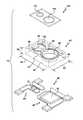
- FIG. 1is an exploded top perspective view of one embodiment of an infrared proximity sensor package
- FIG. 2shows one embodiment of the lens of FIG. 1 ;
- FIG. 3shows top and side views of one embodiment of a receiver die suitable for use in some embodiments of the infrared proximity sensor package disclosed herein;
- FIG. 4shows top and side views of one embodiment of a transmitter die suitable for use in some embodiments of the infrared proximity sensor package disclosed herein;
- FIG. 5shows top and side views of another embodiment of the infrared proximity sensor package disclosed herein;
- FIG. 6shows a functional block diagram according to yet another embodiment of the infrared proximity sensor package disclosed herein.
- FIG. 7shows various steps according to one method of making the infrared proximity sensor package disclosed herein.
- FIG. 1is an exploded top perspective view of one embodiment of infrared proximity sensor package 10 .
- Lens 110fits atop housing 40 , which in turn sits atop and is attached to lead frame 80 .
- infrared proximity sensor package 10comprises quad flat no lead (QFN) lead frame 80 having infrared transmitter die 70 secured to first frame portion 84 thereof, infrared receiver die 60 secured to second frame portion 82 thereof.
- Lead frame 80is preferably configured to fit beneath housing 40 and engage lower portion 44 thereof.
- Housing 40comprises upper housing portion 42 , lower housing portion 44 , outer sidewalls 46 , and first recess 50 and second recess 48 extending vertically between upper and lower housing portions 42 and 44 .
- First and second recesses 50 and 48are separated by partitioning divider 52 , which in a preferred embodiment is integrally molded to the remainder of housing 40 .
- transmitter die 70is disposed on first frame portion 84 and is positioned within first recess 50 .
- Receiver die 60is disposed on second frame portion 82 and is positioned within second recess 48 .
- At least partitioning divider 52 of housing 40comprises liquid crystal polymer (LCP) such that infrared light internally-reflected within housing 40 between first and second recesses 50 and 48 and in the direction of partitioning divider 52 is substantially attenuated or absorbed by the LCP contained therein, more about which is said below.
- LCPliquid crystal polymer
- housing thickness 58most preferably ranges between about 0.3 mm and about 0.5 mm
- housing width 54most preferably ranges between about 2 mm and about 8 mm
- housing length 56most preferably ranges between about 2 mm and about 8 mm.
- FIGS. 1 and 2also show lens assembly 110 , which in a preferred embodiment comprises first and second lenses 112 and 114 configured to fit, respectively, over first recess 50 and second recess 48 such that infrared light transmitted upwardly by transmitter die 70 through first lens 112 is collimated and focused in an upward predetermined direction, and such that infrared light arriving at second lens 114 from a downward direction is collimated and focused towards receiver die 60 .
- lens assembly 110which in a preferred embodiment comprises first and second lenses 112 and 114 configured to fit, respectively, over first recess 50 and second recess 48 such that infrared light transmitted upwardly by transmitter die 70 through first lens 112 is collimated and focused in an upward predetermined direction, and such that infrared light arriving at second lens 114 from a downward direction is collimated and focused towards receiver die 60 .
- first lens 112 and second lens 114are illustrated in FIG.
- lens assembly 110other types of lens configurations are also contemplated, such as separate first and second lenses 112 and 114 , concave lenses, convex lenses, compound lenses, fresnel lenses, and other types of lenses known to those skilled in the art capable of being configured to collimate and/or focus infrared light.
- first and second lenses 112 and 114concave lenses, convex lenses, compound lenses, fresnel lenses, and other types of lenses known to those skilled in the art capable of being configured to collimate and/or focus infrared light.
- lens assembly 110is formed of a suitable thermoset epoxy material, which may be poured atop transmitter die 70 into first recess 50 and atop receiver die 60 into second recess 48 , and then cured at a suitable elevated temperature until sufficiently hardened.
- lens assembly 110is formed of HYSOLTM CNB 897-21 or 22 thermoset epoxy manufactured by LOCTITETM Corporation. These two-part low-viscosity materials may be tinted black to permit infrared transmittance but little or no transmittance of light having wavelengths below about 750 nm or about 700 nm, and thus can be configured to act as low-cut filters.
- lens assembly 110may be configured to act as a low-cut filter that at least partially rejects wavelengths of light less than about 700 nm or about 750 nm.
- cure temperaturescan range between about 85 degrees centigrade and about 100 degrees Centigrade, and cure times can range between about 90 minutes and about 5 and half hours.
- FIG. 2shows further details of lens assembly 110 of FIG. 1 .
- lens assembly thickness 62most preferably ranges between about 0.2 mm and about 0.5 mm
- lens assembly width 68most preferably ranges between about 3 mm and about 5 mm
- lens assembly length 66most preferably ranges between about 3 mm and about 8 mm.
- FIG. 3shows top and side views of one embodiment of receiver die 70 suitable for use in some embodiments of infrared proximity sensor package 10 disclosed herein.
- receiver die 70is a photodiode chip manufactured by TYNTEK having model number TK-043 PD and comprises anode 132 having dimensions of 4 mm by 4 mm, cathode 152 , thickness 76 of 12 mm, first width 72 of 34 mm, and second width 74 of 43 mm.
- receiver 70may be any one of a PIN diode, a photo-diode and a phototransistor.
- FIG. 4shows top and side views of one embodiment of transmitter die 60 suitable for use in some embodiments of infrared proximity sensor package 10 disclosed herein.
- transmitter die 60is P/N mesa type AlGaAs/GaAs infrared chip, also manufactured by TYNTEK, having model number TK 114IRA and comprises P electrode 136 , AlGaAs P epi layer 136 m GaAs P epi layer 142 , GaAs N epi layer 144 , GaAs N substrate 146 and N electrode 148 .
- Transmitter die dimensions 76 and 78are, respectively, 305 mm and 355 mm.
- the thickness of transmitter die 60 illustrated in FIG. 4is 12 mm.
- transmitter 70 and receiver 60are configured for operation within a bandwidth ranging between about 800 nm and about 1100 mm, or between about 850 nm and about 900 nm. 11.
- an edge of transmitter die 70 closest to an edge of receiver die 60is optimally less than about 2 mm so that package 10 may be made as small as practicable.
- FIG. 5shows top and side views of another embodiment of infrared proximity sensor package 10 disclosed herein.
- Package 10 illustrated in FIG. 5is particularly efficacious owing to its overall small size. For example, width 54 is only 4.5 mm, length 56 is only 4.5 mm, and thickness 58 is only 1.2 mm.
- Transmitter 70is disposed within first recess or cavity 50 , and is separated from second cavity 48 by partitioning divider 52 .
- Receiver die 60is disposed in second cavity 48 along with processor or ASIC 90 , which in a preferred embodiment is operably connected to transmitter die 70 and receiver die 60 by means of wirebonding (not shown in FIG. 5 ).
- terminal pins 101 through 110are also operably connected to processor 90 , transmitter die 70 and receiver die 60 , as the case may be, by wirebond connections 101 a though 110 a shown in FIG. 5 .
- solder ball and bump techniquesball grid array techniques
- ball grid array techniquesor other techniques such as forming conventional solder connections.
- Terminal pin width 154is 0.3 mm, while terminal pin length 152 is 0.7 mm.
- Center-to-center distance 104 between transmitter die 70 and receiver die 60is 2.15 mm.
- Outer sidewalls 46 and inner sidewalls 47define the respective outer and inner perimeters of housing 40 , along with portioning divider 52 .
- the horizontal thickness of portioning divider 52is about 0.8 mm on the upper side thereof, and about 0.3 mm on the left-hand side thereof.
- Not shown in FIG. 5is a lead frame to which dice 60 , 70 and 90 are attached, and which is secured to a bottom portion of housing 40 .
- Other meansmay also be employed to operably associate such dice with housing 40 , such as a printed circuit board or other type of substrate.
- Terminal pins 101 a through 110 aare configured to permit electrical connection of package 10 to one or more electronic devices external thereto.
- Sensor package 10may be incorporated into or operably connected to one or more of a portable electronic device, a hand-held portable electronic device, a stationary electronic device, a washing machine, a dryer, an exercise machine, an industrial control or switching device, a camera, a toy, a mobile telephone, a cellular telephone, a portable music player, a remote control, a television, an air conditioning unit, a heating unit, an audio playback device, an audio recording device, an MP3 player, a laptop computer, a personal data assistant (PDA), a radio, a transceiver, a telephone, an auto-volume adjustment circuit, and an open-phone detection circuit (such as may be employed in a clamshell-style mobile phone).
- PDApersonal data assistant
- dividing partition 52has a thickness less than about 0.4 mm, package 10 has a width or a length less than about 5 mm, and/or a height less than at least one of about 3 mm, about 2 mm, and about 1.2 mm.
- housing 40comprises upper housing portion 42 , lower housing portion 44 , outer sidewalls 46 , inner sidewalls 47 , first recess 50 and second recess 48 .
- first and second recesses 50 and 48are separated by partitioning divider 52 , which in a preferred embodiment is integrally molded to other portions of housing 40 .
- the entire housingis injection molded from LCP.
- at least dividing partition 52comprises LCP, and one or more of outer sidewalls 46 , upper housing portion 42 , lower housing portion 44 comprises LCP.
- an admixture of LCP and a suitable polymeris employed to form housing 40 or various portions thereof.
- dividing partition 52may be formed of LCP, while the remaining portions of housing 40 are formed from plastic, a polymer, or a metal or metal alloy.
- at least portions of lead 80 frameare moldably integrated into housing 40 .
- dividing partition 52 and preferably other portions of hosing 40are formed of LCP such that infrared light internally-reflected within the housing in the direction of dividing partition 52 and/or other portions of housing 40 is substantially attenuated or absorbed by the LCP contained therein.
- Table 1shows the unusual infrared radiation absorption and attenuation properties of LCP employed in the housing of the present invention.
- Table 1shows the results of crosstalk measurements made using infrared transmitters and receivers placed in adjoining first and second cavities separated by sidewalls made of different materials.
- AVAGO TECHNOLOGIESTM HSDL-9100 proximity sensor packageswere adapted to provide housings formed of different materials, and crosstalk was then measured.
- Table 1shows that an LCP housing provides crosstalk isolation performance similar to that of a housing formed from ceramic that is almost twice as thick.
- the housing of the inventionmay also be formed using well-known conventional injection molding processes, which from manufacturing and cost standpoints provides significant advantages respecting ceramic.
- LCPs having suitable compositions and properties for use in infrared proximity sensor housingsmay be obtained from suppliers such as SOLVAY ADVANCED POLYMERSTM located at 4500 McGinnis Ferry Road, Alpharetta, Ga. 3005-3914.
- SOLVAY ADVANCED POLYMERSTMlocated at 4500 McGinnis Ferry Road, Alpharetta, Ga. 3005-3914.
- One type of LCP manufactured by Solvay Advanced Polymersthat has been demonstrated to be particularly efficacious for forming housings of the present invention is XYDAR G-930, which is an LCP plastic material with filler and 30% glass fiber reinforcement.
- XYDAR G-930 LCPis a glass reinforced injection molding grade polymer developed specifically for electronic applications utilizing surface mount technology, and features excellent moldability characteristics.
- XYDAR G-930 resincan fill very thin walls over long flow lengths with little or no flash, even at mold temperatures below 200° F. (93° C.). In addition, it has low warpage in molded products and exceptional weld line strength. Like many other LCPs, XYDAR G-930 exhibits high strength and stiffness (even at elevated temperatures), a low coefficient of thermal expansion, a high deflection temperature, inherent flame resistance, and strong resistance to most chemicals, weathering, and radiation. In addition to SOLVAY ADVANCED POLYMENRS, other manufacturers of LCP include AMOCO PERFORMANCE PRODUCTSTM and HOECHST CELANESE CORPORATIONTM. Formulations of LCP suitable for use in forming the housings of the present invention include, but are not limited to, those which are biphenol-based and napthaline-based.
- LCPsare relatively inert. They resist stress cracking in the presence of most chemicals at elevated temperatures, including aromatic or halogenated hydrocarbons, strong acids, bases, ketones, and other aggressive industrial substances. Hydrolytic stability in boiling water is also good. Easy processability of LCP resins may be attributed to their liquid-crystal molecular structure, which provides high melt flow and fast setup in molded parts. The physical properties of parts molded from LCP are generally not affected by minor variations in processing conditions, and thus little or no post-curing is required.
- FIG. 6shows a functional block diagram according to yet another embodiment of infrared proximity sensor package 10 disclosed herein, where processor or ASIC 90 is operably connected to PIN receiver 60 and VLED receiver 70 .
- Processor 90preferably comprises transmitter driving circuitry, receiver detection circuitry and signal conditioning circuitry, and in preferred embodiments is an application specific integrated circuit (ASIC).
- Terminal pins 101 through 110are operably connected to processor 90 , transmitter 70 and receiver 60 by wirebonding or other suitable means known to those skilled in the art.
- infrared proximity sensor package 10comprising providing infrared transmitter die 70 , providing infrared receiver die 60 , providing housing 40 comprising upper housing portion 42 and lower housing portion 44 , outer sidewalls 46 , first recess 50 , second recess 48 , first and second recesses 50 and 48 being separated by partitioning divider 52 , at least partitioning divider 52 of housing 40 comprising LCP such that infrared light internally-reflected within housing 40 in the direction of partitioning divider 52 is substantially attenuated or absorbed by the LCP contained therein.
- Such a methodmay further comprise any one or more of: (a) providing a lead frame configured to fit beneath the housing and engage the lower portions thereof, the lead frame comprising first and second frame portions; (b) attaching the lead frame to the lower housing portion; (c) disposing the transmitter die on the first frame portion and positioning the transmitter die within the first recess; (d) disposing the receiver die on the second frame portion and positioning the receiver die within the second recess; (e) molding the housing from LCP; and/or (f) integrably molding at least portions of the lead frame into the housing.
- Other methods of making or using package 10 or housing 40are also contemplated, such as providing a housing frame or components made of a material other than LCP and coating or laminating same with LCP by injection molding or other means.
- FIG. 7shows another method comprising making lead frame 80 (step 162 ), molding housing 40 and incorporating lead frame 80 therein (step 164 ), attaching integrated circuit dice 60 and 70 inside housing 40 (step 166 ), wirebonding dice 60 and 70 to terminals incorporated into or attached to housing 40 (step 168 ), encapsulating first and second cavities 50 and 48 with a flowable transparent material, preferably although not necessarily a thermoset epoxy, thereby to form a lens over dice 60 and 70 (step 170 ), and testing the functionality of chips 60 and 70 (step 172 ).
- a flowable transparent materialpreferably although not necessarily a thermoset epoxy
- While the primary use of the input device of the present inventionis believed likely to be in the context of relatively small portable devices, it may also be of value in the context of larger devices, including, for example, keyboards associated with desktop computers or other less portable devices such as, by way of non-limiting example only, exercise equipment, industrial control panels, or washing machines.
Landscapes
- Physics & Mathematics (AREA)
- Engineering & Computer Science (AREA)
- Electromagnetism (AREA)
- Computer Networks & Wireless Communication (AREA)
- General Physics & Mathematics (AREA)
- Radar, Positioning & Navigation (AREA)
- Remote Sensing (AREA)
- Light Receiving Elements (AREA)
- Photometry And Measurement Of Optical Pulse Characteristics (AREA)
Abstract
Description
| TABLE 1 |
| Crosstalk Measured in Infrared Proximity Sensor Packages |
| Having Housings Formed of Different Materials |
| Thickness of | Amount of | ||||
| Partitioning | Photocurrent | Crosstalk | |||
| Housing Type | Divider | Developed | Measured | ||
| Stainless Steel | 0.1 mm | 350 nA | 35 mV | ||
| Ceramic | 0.3 mm | 1.15 uA | 115 mV | ||
| Ceramic | 0.5 | 90 nA | 9 mv | ||
| Aluminum Foil | 0.2 mm | 150 nA | 15 mV | ||
| Liquid Crystal | 0.3 | 120 nA | 12 mV | ||
| Polymer (LCP) | |||||
Claims (31)
Priority Applications (1)
| Application Number | Priority Date | Filing Date | Title |
|---|---|---|---|
| US11/962,535US8217482B2 (en) | 2007-12-21 | 2007-12-21 | Infrared proximity sensor package with reduced crosstalk |
Applications Claiming Priority (1)
| Application Number | Priority Date | Filing Date | Title |
|---|---|---|---|
| US11/962,535US8217482B2 (en) | 2007-12-21 | 2007-12-21 | Infrared proximity sensor package with reduced crosstalk |
Publications (2)
| Publication Number | Publication Date |
|---|---|
| US20090159900A1 US20090159900A1 (en) | 2009-06-25 |
| US8217482B2true US8217482B2 (en) | 2012-07-10 |
Family
ID=40787525
Family Applications (1)
| Application Number | Title | Priority Date | Filing Date |
|---|---|---|---|
| US11/962,535Active2030-10-05US8217482B2 (en) | 2007-12-21 | 2007-12-21 | Infrared proximity sensor package with reduced crosstalk |
Country Status (1)
| Country | Link |
|---|---|
| US (1) | US8217482B2 (en) |
Cited By (14)
| Publication number | Priority date | Publication date | Assignee | Title |
|---|---|---|---|---|
| US20120057858A1 (en)* | 2010-09-08 | 2012-03-08 | Kabushiki Kaisha Toshiba | Camera module |
| US20120223231A1 (en)* | 2011-03-01 | 2012-09-06 | Lite-On Singapore Pte. Ltd. | Proximity sensor having electro-less plated shielding structure |
| CN103162719A (en)* | 2013-01-23 | 2013-06-19 | 苏州佳世达电通有限公司 | Remote control sensing module |
| US8604436B1 (en)* | 2011-03-24 | 2013-12-10 | Maxim Integrated Products, Inc. | Proximity sensor device |
| US20150001414A1 (en)* | 2012-01-13 | 2015-01-01 | Panasonic Corporation | Proximity sensor |
| US9024810B2 (en) | 2009-01-27 | 2015-05-05 | Xyz Interactive Technologies Inc. | Method and apparatus for ranging finding, orienting, and/or positioning of single and/or multiple devices |
| US20160187483A1 (en)* | 2014-12-24 | 2016-06-30 | Stmicroelectronics Pte Ltd | Molded proximity sensor |
| US9632209B2 (en) | 2015-03-25 | 2017-04-25 | Hana Microelectronics, Inc. | Proximity sensor with light blocking compound |
| US20190118972A1 (en)* | 2016-06-17 | 2019-04-25 | Sz Dji Osmo Technology Co., Ltd. | Holding apparatus |
| US10320384B2 (en) | 2014-06-02 | 2019-06-11 | Xyz Interactive Technologies Inc. | Touch-less switching |
| US10452157B2 (en) | 2014-10-07 | 2019-10-22 | Xyz Interactive Technologies Inc. | Device and method for orientation and positioning |
| US10591607B2 (en) | 2013-03-28 | 2020-03-17 | Carrier Corporation | Tracking device |
| US11005001B2 (en)* | 2011-07-19 | 2021-05-11 | Ams Sensors Singapore Pte. Ltd. | Opto-electronic modules and methods of manufacturing the same and appliances and devices comprising the same |
| US20240103170A1 (en)* | 2020-06-23 | 2024-03-28 | Audio Authority Corporation | Touchless Sensor and Method for Retrofitting a Touchless Sensor into Push-Button Receiver |
Families Citing this family (40)
| Publication number | Priority date | Publication date | Assignee | Title |
|---|---|---|---|---|
| US8217482B2 (en) | 2007-12-21 | 2012-07-10 | Avago Technologies General Ip (Singapore) Pte. Ltd. | Infrared proximity sensor package with reduced crosstalk |
| TW201032319A (en)* | 2009-02-25 | 2010-09-01 | Everlight Electronics Co Ltd | Semiconductor optoelectronic device and quad flat non-leaded optoelectronic device |
| EP2224486A3 (en)* | 2009-02-25 | 2012-09-12 | Everlight Electronics Co., Ltd. | Quad flat non-leaded chip package structure |
| US8420999B2 (en)* | 2009-05-08 | 2013-04-16 | Avago Technologies Ecbu Ip (Singapore) Pte. Ltd. | Metal shield and housing for optical proximity sensor with increased resistance to mechanical deformation |
| US8779361B2 (en)* | 2009-06-30 | 2014-07-15 | Avago Technologies General Ip (Singapore) Pte. Ltd. | Optical proximity sensor package with molded infrared light rejection barrier and infrared pass components |
| US9525093B2 (en) | 2009-06-30 | 2016-12-20 | Avago Technologies General Ip (Singapore) Pte. Ltd. | Infrared attenuating or blocking layer in optical proximity sensor |
| US8957380B2 (en)* | 2009-06-30 | 2015-02-17 | Avago Technologies General Ip (Singapore) Pte. Ltd. | Infrared attenuating or blocking layer in optical proximity sensor |
| US8097852B2 (en)* | 2009-09-10 | 2012-01-17 | Avago Technologies Ecbu Ip (Singapore) Pte. Ltd. | Multiple transfer molded optical proximity sensor and corresponding method |
| US8716665B2 (en) | 2009-09-10 | 2014-05-06 | Avago Technologies General Ip (Singapore) Pte. Ltd. | Compact optical proximity sensor with ball grid array and windowed substrate |
| US8143608B2 (en)* | 2009-09-10 | 2012-03-27 | Avago Technologies Ecbu Ip (Singapore) Pte. Ltd. | Package-on-package (POP) optical proximity sensor |
| US8350216B2 (en)* | 2009-09-10 | 2013-01-08 | Avago Technologies Ecbu Ip (Singapore) Pte. Ltd. | Miniaturized optical proximity sensor |
| KR20110047600A (en)* | 2009-10-30 | 2011-05-09 | 삼성전자주식회사 | Proximity sensing electronics |
| US8502153B2 (en)* | 2009-11-20 | 2013-08-06 | Avago Technologies General Ip (Singapore) Pte. Ltd. | Methods, systems and devices for crosstalk measurement and cancellation in optical proximity sensors |
| US9733357B2 (en)* | 2009-11-23 | 2017-08-15 | Avago Technologies General Ip (Singapore) Pte. Ltd. | Infrared proximity sensor package with improved crosstalk isolation |
| US8502151B2 (en)* | 2010-01-31 | 2013-08-06 | Avago Technologies General Ip (Singapore) Pte. Ltd. | Optical proximity sensor package with lead frame |
| US8742350B2 (en) | 2010-06-08 | 2014-06-03 | Avago Technologies General Ip (Singapore) Pte. Ltd. | Proximity sensor |
| US8492720B2 (en) | 2010-06-08 | 2013-07-23 | Avago Technologies General Ip (Singapore) Pte. Ltd. | Small low-profile optical proximity sensor |
| US9252767B1 (en)* | 2010-06-28 | 2016-02-02 | Hittite Microwave Corporation | Integrated switch module |
| US8937377B2 (en)* | 2010-10-08 | 2015-01-20 | Avago Technologies General Ip (Singapore) Pte. Ltd. | Package-on-package proximity sensor module |
| US8712485B2 (en) | 2010-11-19 | 2014-04-29 | Apple Inc. | Proximity sensor arrangement in a mobile device |
| US8996082B2 (en) | 2010-11-19 | 2015-03-31 | Apple Inc. | Proximity sensor arrangement having a cold mirror in a mobile device |
| US8841597B2 (en) | 2010-12-27 | 2014-09-23 | Avago Technologies Ip (Singapore) Pte. Ltd. | Housing for optical proximity sensor |
| US8805302B2 (en)* | 2011-05-19 | 2014-08-12 | Apple Inc. | Proximity and ambient light sensor with improved smudge rejection |
| CN102301684B (en)* | 2011-06-24 | 2014-01-22 | 华为终端有限公司 | Method and device for a terminal to determine approach of an object |
| US9366752B2 (en)* | 2011-09-23 | 2016-06-14 | Apple Inc. | Proximity sensor with asymmetric optical element |
| TWI567953B (en) | 2011-12-20 | 2017-01-21 | 新加坡恒立私人有限公司 | Photoelectric module and device comprising the same |
| US20120176599A1 (en)* | 2012-03-16 | 2012-07-12 | Hong Kong Applied Science And Technology Research Institute Co. Ltd. | Optical transceiver |
| US8791489B2 (en)* | 2012-04-05 | 2014-07-29 | Heptagon Micro Optics Pte. Ltd. | Opto-electronic module |
| US9746349B2 (en) | 2013-09-02 | 2017-08-29 | Heptagon Micro Optics Pte. Ltd. | Opto-electronic module including a non-transparent separation member between a light emitting element and a light detecting element |
| CN110346805B (en)* | 2014-12-24 | 2023-06-23 | 意法半导体有限公司 | Proximity sensor |
| KR20160103415A (en)* | 2015-02-24 | 2016-09-01 | 엘지이노텍 주식회사 | Proximity Sensor and Camera Module with the Proximity Sensor and Mobile Terminal Equipped with the Camera Module |
| CN107431049A (en)* | 2015-03-24 | 2017-12-01 | 英特尔公司 | The manufacture method of optical module including electronic packing piece |
| US20160307881A1 (en) | 2015-04-20 | 2016-10-20 | Advanced Semiconductor Engineering, Inc. | Optical sensor module and method for manufacturing the same |
| CN105958990B (en)* | 2016-05-24 | 2019-03-29 | 内蒙古包钢钢联股份有限公司 | Photoelectric proximity switch protective device |
| CN105978544B (en)* | 2016-05-27 | 2019-07-12 | 深圳市劲拓自动化设备股份有限公司 | A kind of optoelectronic switch protective device |
| US11143551B2 (en) | 2018-05-18 | 2021-10-12 | Hana Microelectronics, Inc. | Proximity sensor with infrared ink coating |
| US11520074B2 (en) | 2018-09-14 | 2022-12-06 | Hana Microelectronics, Inc. | Proximity sensor with light blocking barrier comprising a gap having a cross-section with parallel walls between emitter and detector |
| US11567198B2 (en) | 2019-03-25 | 2023-01-31 | Hana Microelectronics Inc. | Proximity sensor with light inhibiting barrier comprising a gap having a cross-section with parallel walls substantially perpendicular to the top surface of an optically transmissive material |
| CN112310244A (en)* | 2020-10-28 | 2021-02-02 | 深圳市柯瑞光电科技有限公司 | A kind of manufacturing method of single pair tube and application keyboard |
| CN113257926A (en)* | 2021-05-12 | 2021-08-13 | 深圳市汇春科技股份有限公司 | Method for packaging image sensor and light filtering glue packaging sensor |
Citations (53)
| Publication number | Priority date | Publication date | Assignee | Title |
|---|---|---|---|---|
| US5155777A (en) | 1991-06-26 | 1992-10-13 | International Business Machines Corporation | Scattered light blocking layer for optoelectronic receivers |
| US5367393A (en) | 1992-03-06 | 1994-11-22 | Seiko Epson Corporation | Electro-optical apparatus with metal light shield and conductor between color filters |
| US5675143A (en) | 1994-12-22 | 1997-10-07 | Optosys Ag | Proximity switch |
| US6064062A (en) | 1998-06-02 | 2000-05-16 | Hewlett-Packard Company | Optical stray light baffle for image scanner |
| US6135816A (en) | 1998-04-27 | 2000-10-24 | Ddk Ltd. | Electrical connector having an improved construction for fixing shield plates to a receptacle connector |
| US6180881B1 (en) | 1998-05-05 | 2001-01-30 | Harlan Ruben Isaak | Chip stack and method of making same |
| US6364706B1 (en) | 1998-10-19 | 2002-04-02 | Molex Incorporated | Shielded electrical connector with flange support member |
| US20020172472A1 (en) | 2001-04-09 | 2002-11-21 | Steven Nelson | Optical attenuating underchip encapsulant |
| US6572410B1 (en) | 2002-02-20 | 2003-06-03 | Fci Americas Technology, Inc. | Connection header and shield |
| US6635955B2 (en)* | 2000-11-15 | 2003-10-21 | Vishay Semiconductor Gmbh | Molded electronic component |
| US6674653B1 (en) | 1999-04-16 | 2004-01-06 | Agilent Technologies, Inc. | Shielding scheme for a circuit board |
| US20040065894A1 (en)* | 2001-08-28 | 2004-04-08 | Takuma Hashimoto | Light emitting device using led |
| EP1455564A1 (en) | 2003-03-05 | 2004-09-08 | Sony Ericsson Mobile Communications AB | Electronic device provided with an EMI shield |
| US6885300B1 (en) | 2002-06-05 | 2005-04-26 | The Watt Stopper, Inc. | Broad field motion detector |
| US20050110157A1 (en)* | 2003-09-15 | 2005-05-26 | Rohm And Haas Electronic Materials, L.L.C. | Device package and method for the fabrication and testing thereof |
| US20060017069A1 (en) | 2002-02-18 | 2006-01-26 | Robert Bergmann | Electronic component with an adhesive layer and method for the production thereof |
| US20060016994A1 (en) | 2004-07-22 | 2006-01-26 | Suresh Basoor | System and method to prevent cross-talk between a transmitter and a receiver |
| US20060022212A1 (en)* | 1997-12-15 | 2006-02-02 | Osram Gmbh, A Germany Corporation | Surface mounting optoelectronic component and method for producing same |
| US20060022215A1 (en)* | 2003-01-30 | 2006-02-02 | Karlheinz Arndt | Semiconductor component emitting and/or receiving electromagnetic radiation, and housing base for such a component |
| US7026710B2 (en) | 2000-01-21 | 2006-04-11 | Texas Instruments Incorporated | Molded package for micromechanical devices and method of fabrication |
| US20060118807A1 (en)* | 2004-12-08 | 2006-06-08 | Ives Fred H | Electronic microcircuit having internal light enhancement |
| US7172126B2 (en) | 1998-12-03 | 2007-02-06 | Metrologic Instruments, Inc. | Wireless automatic laser scanning bar code symbol reading system, wherein the RF-based transceiver chipsets within the wireless hand-supportable unit and base station thereof are automatically deactivated and said RF data communication link therebetween terminated when said system enters its power-saving sleep mode, and reactivated and re-established when re-entering its operational mode |
| US20070045524A1 (en) | 2003-06-23 | 2007-03-01 | Advanced Optical Technologies, Llc | Intelligent solid state lighting |
| US7229295B2 (en) | 2004-02-27 | 2007-06-12 | Finisar Corporation | Transceiver module having a dual segment lead frame connector |
| US7256483B2 (en) | 2004-10-28 | 2007-08-14 | Philips Lumileds Lighting Company, Llc | Package-integrated thin film LED |
| US7258264B2 (en) | 2004-02-27 | 2007-08-21 | Finisar Corporation | Methods for manufacturing optical modules using lead frame connectors |
| US7289142B2 (en) | 1997-07-15 | 2007-10-30 | Silverbrook Research Pty Ltd | Monolithic integrated circuit having a number of programmable processing elements |
| US20080006762A1 (en) | 2005-09-30 | 2008-01-10 | Fadell Anthony M | Integrated proximity sensor and light sensor |
| US20080011939A1 (en) | 2006-07-13 | 2008-01-17 | Pak Hong Yee | Composite assembly that incorporates multiple devices that use different wavelengths of light and method for making same |
| US20080011940A1 (en) | 2006-07-13 | 2008-01-17 | Jing Zhang | Remote control receiver device and ambient light photosensor device incorporated into a single composite assembly |
| US20080012033A1 (en)* | 2004-05-31 | 2008-01-17 | Karlheinz Arndt | Optoelectronic Semiconductor Component and Housing Base for Such a Component |
| US20080049210A1 (en) | 2006-08-28 | 2008-02-28 | Sharp Kabushiki Kaisha | Range-finding sensor, and electronic device equipped with range-finding sensor |
| US20080118241A1 (en) | 2006-11-16 | 2008-05-22 | Tekolste Robert | Control of stray light in camera systems employing an optics stack and associated methods |
| US20080116379A1 (en) | 2006-11-16 | 2008-05-22 | Pilkington North America | Multi-mode rain sensor |
| US7387033B2 (en) | 2005-06-17 | 2008-06-17 | Acellent Technologies, Inc. | Single-wire sensor/actuator network for structure health monitoring |
| US7387907B2 (en) | 2004-06-17 | 2008-06-17 | Taiwan Semiconductor Manufacturing Co., Ltd. | Image sensor with optical guard ring and fabrication method thereof |
| US20080173963A1 (en) | 2007-01-24 | 2008-07-24 | Taiwan Semiconductor Manufacturing Company, Ltd. | Guard ring structure for improving crosstalk of backside illuminated image sensor |
| US20080197376A1 (en) | 2005-02-28 | 2008-08-21 | Braune Bert | Method for Producing an Optical, Radiation-Emitting Component and Optical, Radiation-Emitting Component |
| US20080265266A1 (en)* | 2004-09-22 | 2008-10-30 | Osram Opto Semiconductors Gmbh | Housing for an Optoelectronic Component, Optoelectronic Component and Method for the Production of an Optoelectronic Component |
| US20080296478A1 (en) | 2007-06-01 | 2008-12-04 | Thierry Hernoult | Methods for reducing cross talk in optical sensors |
| US20080308738A1 (en) | 2007-06-15 | 2008-12-18 | Wen Li | Structure of a solid state photomultiplier |
| US20080308917A1 (en) | 2007-06-13 | 2008-12-18 | Infineon Technologies Ag | Embedded chip package |
| US20090027652A1 (en) | 2007-07-25 | 2009-01-29 | Tom Chang | Integrated ambient light sensor and distance sensor |
| US7510888B2 (en) | 2004-04-30 | 2009-03-31 | Osram Opto Semiconductors Gmbh | LED arrangement |
| US20090101804A1 (en) | 2006-04-21 | 2009-04-23 | Koninklijke Philips Electronics N.V. | Detection circuit for detecting movements of a movable object |
| US20090129783A1 (en) | 2006-02-28 | 2009-05-21 | Fujikura Ltd. | Bi-directional optical module |
| WO2009072786A2 (en) | 2007-12-06 | 2009-06-11 | Seoul Semiconductor Co., Ltd. | Led package and method for fabricating the same |
| US20090159900A1 (en) | 2007-12-21 | 2009-06-25 | Avagon Tewchnologies General Ip (Singapore) Pte. Ltd. | Infrared Proximity Sensor Package with Reduced Crosstalk |
| US20100030039A1 (en) | 2008-08-04 | 2010-02-04 | Masimo Laboratories, Inc. | Multi-stream sensor front ends for noninvasive measurement of blood constituents |
| US7767485B2 (en) | 2008-08-01 | 2010-08-03 | Kabushiki Kaisha Toshiba | Solid-state imaging device and method for manufacturing same |
| US20100246771A1 (en) | 2009-03-30 | 2010-09-30 | Hawver Jeffery R | Magnetic shielding for portable detector |
| US20100282951A1 (en) | 2009-05-08 | 2010-11-11 | Avago Technologies Ecbu (Singapore) Pte. Ltd. | Metal Shield and Housing for Optical Proximity Sensor with Increased Resistance to Mechanical Deformation |
| US20110057104A1 (en) | 2009-09-10 | 2011-03-10 | Avago Technologies Ecbu (Singapore) Pte. Ltd. | Miniaturized Optical Proximity Sensor |
Family Cites Families (2)
| Publication number | Priority date | Publication date | Assignee | Title |
|---|---|---|---|---|
| US7026410B2 (en)* | 2002-10-17 | 2006-04-11 | Henkel Corporation | Solventless method for preparation of carboxylic polymers |
| US7109465B2 (en)* | 2003-04-04 | 2006-09-19 | Avago Technologies Ecbu Ip (Singapore) Pte., Ltd. | System and method for converting ambient light energy into a digitized electrical output signal for controlling display and keypad illumination on a battery powered system |
- 2007
- 2007-12-21USUS11/962,535patent/US8217482B2/enactiveActive
Patent Citations (58)
| Publication number | Priority date | Publication date | Assignee | Title |
|---|---|---|---|---|
| US5155777A (en) | 1991-06-26 | 1992-10-13 | International Business Machines Corporation | Scattered light blocking layer for optoelectronic receivers |
| US5367393A (en) | 1992-03-06 | 1994-11-22 | Seiko Epson Corporation | Electro-optical apparatus with metal light shield and conductor between color filters |
| US5675143A (en) | 1994-12-22 | 1997-10-07 | Optosys Ag | Proximity switch |
| US7289142B2 (en) | 1997-07-15 | 2007-10-30 | Silverbrook Research Pty Ltd | Monolithic integrated circuit having a number of programmable processing elements |
| US7675132B2 (en)* | 1997-12-15 | 2010-03-09 | Osram Gmbh | Surface mounting optoelectronic component and method for producing same |
| US20060022212A1 (en)* | 1997-12-15 | 2006-02-02 | Osram Gmbh, A Germany Corporation | Surface mounting optoelectronic component and method for producing same |
| US6135816A (en) | 1998-04-27 | 2000-10-24 | Ddk Ltd. | Electrical connector having an improved construction for fixing shield plates to a receptacle connector |
| US6180881B1 (en) | 1998-05-05 | 2001-01-30 | Harlan Ruben Isaak | Chip stack and method of making same |
| US6064062A (en) | 1998-06-02 | 2000-05-16 | Hewlett-Packard Company | Optical stray light baffle for image scanner |
| US6364706B1 (en) | 1998-10-19 | 2002-04-02 | Molex Incorporated | Shielded electrical connector with flange support member |
| US7172126B2 (en) | 1998-12-03 | 2007-02-06 | Metrologic Instruments, Inc. | Wireless automatic laser scanning bar code symbol reading system, wherein the RF-based transceiver chipsets within the wireless hand-supportable unit and base station thereof are automatically deactivated and said RF data communication link therebetween terminated when said system enters its power-saving sleep mode, and reactivated and re-established when re-entering its operational mode |
| US6674653B1 (en) | 1999-04-16 | 2004-01-06 | Agilent Technologies, Inc. | Shielding scheme for a circuit board |
| US7026710B2 (en) | 2000-01-21 | 2006-04-11 | Texas Instruments Incorporated | Molded package for micromechanical devices and method of fabrication |
| US6635955B2 (en)* | 2000-11-15 | 2003-10-21 | Vishay Semiconductor Gmbh | Molded electronic component |
| US20020172472A1 (en) | 2001-04-09 | 2002-11-21 | Steven Nelson | Optical attenuating underchip encapsulant |
| US20040065894A1 (en)* | 2001-08-28 | 2004-04-08 | Takuma Hashimoto | Light emitting device using led |
| US20060017069A1 (en) | 2002-02-18 | 2006-01-26 | Robert Bergmann | Electronic component with an adhesive layer and method for the production thereof |
| US6572410B1 (en) | 2002-02-20 | 2003-06-03 | Fci Americas Technology, Inc. | Connection header and shield |
| US7277012B2 (en) | 2002-06-05 | 2007-10-02 | The Watt Stopper, Inc. | Broad field motion detector |
| US6885300B1 (en) | 2002-06-05 | 2005-04-26 | The Watt Stopper, Inc. | Broad field motion detector |
| US20060022215A1 (en)* | 2003-01-30 | 2006-02-02 | Karlheinz Arndt | Semiconductor component emitting and/or receiving electromagnetic radiation, and housing base for such a component |
| US7427806B2 (en)* | 2003-01-30 | 2008-09-23 | Oram Gmbh | Semiconductor component emitting and/or receiving electromagnetic radiation, and housing base for such a component |
| EP1455564A1 (en) | 2003-03-05 | 2004-09-08 | Sony Ericsson Mobile Communications AB | Electronic device provided with an EMI shield |
| US20070045524A1 (en) | 2003-06-23 | 2007-03-01 | Advanced Optical Technologies, Llc | Intelligent solid state lighting |
| US20070072321A1 (en)* | 2003-09-15 | 2007-03-29 | Rohm And Haas Electronic Materials Llc | Device package and methods for the fabrication and testing thereof |
| US20050110157A1 (en)* | 2003-09-15 | 2005-05-26 | Rohm And Haas Electronic Materials, L.L.C. | Device package and method for the fabrication and testing thereof |
| US7229295B2 (en) | 2004-02-27 | 2007-06-12 | Finisar Corporation | Transceiver module having a dual segment lead frame connector |
| US7258264B2 (en) | 2004-02-27 | 2007-08-21 | Finisar Corporation | Methods for manufacturing optical modules using lead frame connectors |
| US7510888B2 (en) | 2004-04-30 | 2009-03-31 | Osram Opto Semiconductors Gmbh | LED arrangement |
| US20080012033A1 (en)* | 2004-05-31 | 2008-01-17 | Karlheinz Arndt | Optoelectronic Semiconductor Component and Housing Base for Such a Component |
| US7387907B2 (en) | 2004-06-17 | 2008-06-17 | Taiwan Semiconductor Manufacturing Co., Ltd. | Image sensor with optical guard ring and fabrication method thereof |
| US20060016994A1 (en) | 2004-07-22 | 2006-01-26 | Suresh Basoor | System and method to prevent cross-talk between a transmitter and a receiver |
| US20080265266A1 (en)* | 2004-09-22 | 2008-10-30 | Osram Opto Semiconductors Gmbh | Housing for an Optoelectronic Component, Optoelectronic Component and Method for the Production of an Optoelectronic Component |
| US7256483B2 (en) | 2004-10-28 | 2007-08-14 | Philips Lumileds Lighting Company, Llc | Package-integrated thin film LED |
| US20060118807A1 (en)* | 2004-12-08 | 2006-06-08 | Ives Fred H | Electronic microcircuit having internal light enhancement |
| US20080197376A1 (en) | 2005-02-28 | 2008-08-21 | Braune Bert | Method for Producing an Optical, Radiation-Emitting Component and Optical, Radiation-Emitting Component |
| US7387033B2 (en) | 2005-06-17 | 2008-06-17 | Acellent Technologies, Inc. | Single-wire sensor/actuator network for structure health monitoring |
| US20080006762A1 (en) | 2005-09-30 | 2008-01-10 | Fadell Anthony M | Integrated proximity sensor and light sensor |
| US20090129783A1 (en) | 2006-02-28 | 2009-05-21 | Fujikura Ltd. | Bi-directional optical module |
| US20090101804A1 (en) | 2006-04-21 | 2009-04-23 | Koninklijke Philips Electronics N.V. | Detection circuit for detecting movements of a movable object |
| US7514666B2 (en) | 2006-07-13 | 2009-04-07 | Avago Technologies Ecbu Ip (Singapore) Pte. Ltd. | Composite receiver assembly having a circuit board on which multiple receiver devices that operate on different sets of wavelengths are mounted |
| US20080011940A1 (en) | 2006-07-13 | 2008-01-17 | Jing Zhang | Remote control receiver device and ambient light photosensor device incorporated into a single composite assembly |
| US20080011939A1 (en) | 2006-07-13 | 2008-01-17 | Pak Hong Yee | Composite assembly that incorporates multiple devices that use different wavelengths of light and method for making same |
| US20080049210A1 (en) | 2006-08-28 | 2008-02-28 | Sharp Kabushiki Kaisha | Range-finding sensor, and electronic device equipped with range-finding sensor |
| US20080118241A1 (en) | 2006-11-16 | 2008-05-22 | Tekolste Robert | Control of stray light in camera systems employing an optics stack and associated methods |
| US20080116379A1 (en) | 2006-11-16 | 2008-05-22 | Pilkington North America | Multi-mode rain sensor |
| US20080173963A1 (en) | 2007-01-24 | 2008-07-24 | Taiwan Semiconductor Manufacturing Company, Ltd. | Guard ring structure for improving crosstalk of backside illuminated image sensor |
| US20080296478A1 (en) | 2007-06-01 | 2008-12-04 | Thierry Hernoult | Methods for reducing cross talk in optical sensors |
| US20080308917A1 (en) | 2007-06-13 | 2008-12-18 | Infineon Technologies Ag | Embedded chip package |
| US20080308738A1 (en) | 2007-06-15 | 2008-12-18 | Wen Li | Structure of a solid state photomultiplier |
| US20090027652A1 (en) | 2007-07-25 | 2009-01-29 | Tom Chang | Integrated ambient light sensor and distance sensor |
| WO2009072786A2 (en) | 2007-12-06 | 2009-06-11 | Seoul Semiconductor Co., Ltd. | Led package and method for fabricating the same |
| US20090159900A1 (en) | 2007-12-21 | 2009-06-25 | Avagon Tewchnologies General Ip (Singapore) Pte. Ltd. | Infrared Proximity Sensor Package with Reduced Crosstalk |
| US7767485B2 (en) | 2008-08-01 | 2010-08-03 | Kabushiki Kaisha Toshiba | Solid-state imaging device and method for manufacturing same |
| US20100030039A1 (en) | 2008-08-04 | 2010-02-04 | Masimo Laboratories, Inc. | Multi-stream sensor front ends for noninvasive measurement of blood constituents |
| US20100246771A1 (en) | 2009-03-30 | 2010-09-30 | Hawver Jeffery R | Magnetic shielding for portable detector |
| US20100282951A1 (en) | 2009-05-08 | 2010-11-11 | Avago Technologies Ecbu (Singapore) Pte. Ltd. | Metal Shield and Housing for Optical Proximity Sensor with Increased Resistance to Mechanical Deformation |
| US20110057104A1 (en) | 2009-09-10 | 2011-03-10 | Avago Technologies Ecbu (Singapore) Pte. Ltd. | Miniaturized Optical Proximity Sensor |
Non-Patent Citations (23)
| Title |
|---|
| Agilent HSDL-9100 Miniature Surface-Mount Proximity Sensor Data Sheet; author and date unknown. |
| AlGaAs/GaAs Infrared Chip-TK 114IRA Data Sheet from TYNTEK website: Dec. 19, 2007. |
| Avago Technologies, "APDS-9005 Miniature Surface-Mount Ambient Light Photo Sensor", Jan. 2007. |
| Avago Technologies, "APDS-9101-Integrated Reflective Sensor", Data Sheet 2007. |
| Avago Technologies, "APDS-9700 Signal Conditioning IC for Optical Proximity Sensors", Jan. 4, 2008. |
| Avago Technologies, "HSDL-9100-Surface-Mount Proximity Sensor", Data Sheet 2006. |
| Avago Technologies, "Integrated Ambient Light and Proximity Sensor Prelim Datasheet", APDS-9800 Mar. 2, 2009. |
| Avago Technologies, "Integrated Optical Proximity Sensors Prelim Datasheet", APDS-9120 Feb. 25, 2009. |
| AZ Optics, "Device Debuts as the World's Best-Performing Integrated Light/Proximity Sensor", Nov. 11, 2008. |
| Costello, et al., "U.S. Appl. No. 12/495,739", Optical Proximity Sensor Package with Molded Infrared Light Rejection Barrier and Infrared Pass Components Jun. 30, 2009. |
| Ishihara, et al., "A Dual Face Package Using a Post with Wire Components: Novel Structure for PoP Wafer Level CSP and Compact Image Sensor Package", Electronic Components and Technology Conference 2008 , 1093-1098. |
| Khamal, Ibrahim , "Infra-Red Proximity Sensor (II)", Apr. 4, 2008. |
| Lossee, et al., "A ⅓ Format Image Sensor with Refractory Metal Light Shield for Color Video Applications", Solid State Circuits Conference, Digest of Technical Papers, 36th ISSCC, IEEE International Volume. Feb. 1989 , pp. 90-91. |
| Lossee, et al., "A 1/3 Format Image Sensor with Refractory Metal Light Shield for Color Video Applications", Solid State Circuits Conference, Digest of Technical Papers, 36th ISSCC, IEEE International Volume. Feb. 1989 , pp. 90-91. |
| Nitto Denko Corporation, "Technical Data Sheet", NT-8506 2001. |
| Nitto Denko Corporation, "Technical Data Sheet", NT-MB-IRL3801 2008. |
| Penchem Technologies Data Sheet, "PEMCHEM OP 580", IR Filter Optoelectronic Epoxy Apr. 2009. |
| Penchem Technologies Data Sheet, "PENCHEM OP 579", IR Pass Optoelectronic Epoxy Apr. 2009. |
| Si Photo-Diode Chip-TK 043PD Data Sheet from TYNTEK website; Dec. 19, 2007. |
| Tan, et al., "U.S. Appl. No. 12/623,767", Infrared Proximity Sensor Package with Improved Crosstalk Isolation, filed Nov. 23, 2009, 30 pages. |
| TYNTEK, "Data Sheet for AlGaAs/GaAs Infrared Chip", TK116IRA Nov. 2006. |
| TYNTEK, "Data Sheet for Si Photo-diode Chip", TK 043PD Jun. 2004. |
| XYDAR G-930-Solvay Advanced Ploymers-Liquid Crystal Polymer Data sheet; author unknown; Dec. 17, 2007; reproduced from website at www.ides.com/grades/ds/E22218.htm. |
Cited By (26)
| Publication number | Priority date | Publication date | Assignee | Title |
|---|---|---|---|---|
| US9024810B2 (en) | 2009-01-27 | 2015-05-05 | Xyz Interactive Technologies Inc. | Method and apparatus for ranging finding, orienting, and/or positioning of single and/or multiple devices |
| US8444331B2 (en)* | 2010-09-08 | 2013-05-21 | Kabushiki Kaisha Toshiba | Camera module |
| US20120057858A1 (en)* | 2010-09-08 | 2012-03-08 | Kabushiki Kaisha Toshiba | Camera module |
| US20120223231A1 (en)* | 2011-03-01 | 2012-09-06 | Lite-On Singapore Pte. Ltd. | Proximity sensor having electro-less plated shielding structure |
| US9372264B1 (en) | 2011-03-24 | 2016-06-21 | Maxim Integrated Products, Inc. | Proximity sensor device |
| US8604436B1 (en)* | 2011-03-24 | 2013-12-10 | Maxim Integrated Products, Inc. | Proximity sensor device |
| US8822925B1 (en) | 2011-03-24 | 2014-09-02 | Maxim Integrated Products, Inc. | Proximity sensor device |
| US11005001B2 (en)* | 2011-07-19 | 2021-05-11 | Ams Sensors Singapore Pte. Ltd. | Opto-electronic modules and methods of manufacturing the same and appliances and devices comprising the same |
| US20150001414A1 (en)* | 2012-01-13 | 2015-01-01 | Panasonic Corporation | Proximity sensor |
| US9223054B2 (en)* | 2012-01-13 | 2015-12-29 | Panasonic Intellectual Property Mangement Co., Ltd. | Proximity sensor |
| CN103162719A (en)* | 2013-01-23 | 2013-06-19 | 苏州佳世达电通有限公司 | Remote control sensing module |
| US10591607B2 (en) | 2013-03-28 | 2020-03-17 | Carrier Corporation | Tracking device |
| US11362657B2 (en) | 2014-06-02 | 2022-06-14 | Xyz Interactive Technologies Inc. | Touch-less switching |
| US10320384B2 (en) | 2014-06-02 | 2019-06-11 | Xyz Interactive Technologies Inc. | Touch-less switching |
| US10996768B2 (en) | 2014-10-07 | 2021-05-04 | Xyz Interactive Technologies Inc. | Device and method for orientation and positioning |
| US10452157B2 (en) | 2014-10-07 | 2019-10-22 | Xyz Interactive Technologies Inc. | Device and method for orientation and positioning |
| US10429509B2 (en)* | 2014-12-24 | 2019-10-01 | Stmicroelectronics Pte Ltd. | Molded proximity sensor |
| US20160187483A1 (en)* | 2014-12-24 | 2016-06-30 | Stmicroelectronics Pte Ltd | Molded proximity sensor |
| US11513220B2 (en) | 2014-12-24 | 2022-11-29 | Stmicroelectronics Pte Ltd | Molded proximity sensor |
| US11988743B2 (en) | 2014-12-24 | 2024-05-21 | Stmicroelectronics Pte Ltd | Molded proximity sensor |
| US9632209B2 (en) | 2015-03-25 | 2017-04-25 | Hana Microelectronics, Inc. | Proximity sensor with light blocking compound |
| US10766636B2 (en)* | 2016-06-17 | 2020-09-08 | Sz Dji Osmo Technology Co., Ltd. | Holding apparatus |
| US20190118972A1 (en)* | 2016-06-17 | 2019-04-25 | Sz Dji Osmo Technology Co., Ltd. | Holding apparatus |
| US11365015B2 (en) | 2016-06-17 | 2022-06-21 | Sz Dji Osmo Technology Co., Ltd. | Holding apparatus |
| US20240103170A1 (en)* | 2020-06-23 | 2024-03-28 | Audio Authority Corporation | Touchless Sensor and Method for Retrofitting a Touchless Sensor into Push-Button Receiver |
| US12422551B2 (en)* | 2020-06-23 | 2025-09-23 | Audio Authority Corporation | Touchless sensor and method for retrofitting a touchless sensor into push-button receiver |
Also Published As
| Publication number | Publication date |
|---|---|
| US20090159900A1 (en) | 2009-06-25 |
Similar Documents
| Publication | Publication Date | Title |
|---|---|---|
| US8217482B2 (en) | Infrared proximity sensor package with reduced crosstalk | |
| US9733357B2 (en) | Infrared proximity sensor package with improved crosstalk isolation | |
| US8350216B2 (en) | Miniaturized optical proximity sensor | |
| US8957380B2 (en) | Infrared attenuating or blocking layer in optical proximity sensor | |
| US8502151B2 (en) | Optical proximity sensor package with lead frame | |
| US8716665B2 (en) | Compact optical proximity sensor with ball grid array and windowed substrate | |
| US8097852B2 (en) | Multiple transfer molded optical proximity sensor and corresponding method | |
| JP6328813B2 (en) | Reflowable optoelectronic module | |
| US8143608B2 (en) | Package-on-package (POP) optical proximity sensor | |
| US11828875B2 (en) | Proximity sensor with integrated ALS | |
| CN101164174B (en) | Optical element, optoelectronic device containing the element and its preparation | |
| US4980568A (en) | Optical isolator having high voltage isolation and high light flux light guide | |
| JP5340157B2 (en) | Housing for optoelectronic devices, optoelectronic device, and method of manufacturing housing for optoelectronic devices | |
| US8937377B2 (en) | Package-on-package proximity sensor module | |
| JP2015519545A (en) | Optoelectronic module | |
| US7300217B2 (en) | Optical semiconductor device, optical connector and electronic equipment | |
| JP2011523508A5 (en) | ||
| CN111180346B (en) | Method for manufacturing photoelectric mechanism with retaining wall | |
| KR101457500B1 (en) | Proximity ambient light sensor and its manufacturing method | |
| CN212434647U (en) | Optical chip packaging structure and photoelectric device | |
| CN100382286C (en) | Optical semiconductor devices, optical communication devices, and electronic equipment | |
| JP5650330B2 (en) | Electronic element and soldering method | |
| US11569396B2 (en) | Optical sensor package with optically transparent mold compound | |
| JP6746669B2 (en) | Method for manufacturing photoelectric device with partition wall | |
| JP2986621B2 (en) | Transmission type optical coupling device and method of manufacturing the same |
Legal Events
| Date | Code | Title | Description |
|---|---|---|---|
| AS | Assignment | Owner name:AVAGO TECHNOLOGIES GENERAL IP (SINGAPORE) PTE. LTD Free format text:ASSIGNMENT OF ASSIGNORS INTEREST;ASSIGNORS:BASOOR, SURESH, MR.;NG, PENG YAM, MR.;CHEN, DENG PENG, MR.;REEL/FRAME:020716/0762 Effective date:20071221 | |
| XAS | Not any more in us assignment database | Free format text:ASSIGNMENT OF ASSIGNORS INTEREST;ASSIGNORS:BASOOR, SURESH, MR.;NG, PENG YAM, MR.;CHEN, DENG PENG, MR.;REEL/FRAME:020283/0581 | |
| STCF | Information on status: patent grant | Free format text:PATENTED CASE | |
| AS | Assignment | Owner name:DEUTSCHE BANK AG NEW YORK BRANCH, AS COLLATERAL AGENT, NEW YORK Free format text:PATENT SECURITY AGREEMENT;ASSIGNOR:AVAGO TECHNOLOGIES GENERAL IP (SINGAPORE) PTE. LTD.;REEL/FRAME:032851/0001 Effective date:20140506 Owner name:DEUTSCHE BANK AG NEW YORK BRANCH, AS COLLATERAL AG Free format text:PATENT SECURITY AGREEMENT;ASSIGNOR:AVAGO TECHNOLOGIES GENERAL IP (SINGAPORE) PTE. LTD.;REEL/FRAME:032851/0001 Effective date:20140506 | |
| FPAY | Fee payment | Year of fee payment:4 | |
| AS | Assignment | Owner name:AVAGO TECHNOLOGIES GENERAL IP (SINGAPORE) PTE. LTD., SINGAPORE Free format text:TERMINATION AND RELEASE OF SECURITY INTEREST IN PATENT RIGHTS (RELEASES RF 032851-0001);ASSIGNOR:DEUTSCHE BANK AG NEW YORK BRANCH, AS COLLATERAL AGENT;REEL/FRAME:037689/0001 Effective date:20160201 Owner name:AVAGO TECHNOLOGIES GENERAL IP (SINGAPORE) PTE. LTD Free format text:TERMINATION AND RELEASE OF SECURITY INTEREST IN PATENT RIGHTS (RELEASES RF 032851-0001);ASSIGNOR:DEUTSCHE BANK AG NEW YORK BRANCH, AS COLLATERAL AGENT;REEL/FRAME:037689/0001 Effective date:20160201 | |
| AS | Assignment | Owner name:BANK OF AMERICA, N.A., AS COLLATERAL AGENT, NORTH CAROLINA Free format text:PATENT SECURITY AGREEMENT;ASSIGNOR:AVAGO TECHNOLOGIES GENERAL IP (SINGAPORE) PTE. LTD.;REEL/FRAME:037808/0001 Effective date:20160201 Owner name:BANK OF AMERICA, N.A., AS COLLATERAL AGENT, NORTH Free format text:PATENT SECURITY AGREEMENT;ASSIGNOR:AVAGO TECHNOLOGIES GENERAL IP (SINGAPORE) PTE. LTD.;REEL/FRAME:037808/0001 Effective date:20160201 | |
| AS | Assignment | Owner name:AVAGO TECHNOLOGIES GENERAL IP (SINGAPORE) PTE. LTD., SINGAPORE Free format text:TERMINATION AND RELEASE OF SECURITY INTEREST IN PATENTS;ASSIGNOR:BANK OF AMERICA, N.A., AS COLLATERAL AGENT;REEL/FRAME:041710/0001 Effective date:20170119 Owner name:AVAGO TECHNOLOGIES GENERAL IP (SINGAPORE) PTE. LTD Free format text:TERMINATION AND RELEASE OF SECURITY INTEREST IN PATENTS;ASSIGNOR:BANK OF AMERICA, N.A., AS COLLATERAL AGENT;REEL/FRAME:041710/0001 Effective date:20170119 | |
| AS | Assignment | Owner name:AVAGO TECHNOLOGIES INTERNATIONAL SALES PTE. LIMITE Free format text:MERGER;ASSIGNOR:AVAGO TECHNOLOGIES GENERAL IP (SINGAPORE) PTE. LTD.;REEL/FRAME:047230/0133 Effective date:20180509 | |
| AS | Assignment | Owner name:AVAGO TECHNOLOGIES INTERNATIONAL SALES PTE. LIMITE Free format text:CORRECTIVE ASSIGNMENT TO CORRECT THE EFFECTIVE DATE OF MERGER TO 09/05/2018 PREVIOUSLY RECORDED AT REEL: 047230 FRAME: 0133. ASSIGNOR(S) HEREBY CONFIRMS THE MERGER;ASSIGNOR:AVAGO TECHNOLOGIES GENERAL IP (SINGAPORE) PTE. LTD.;REEL/FRAME:047630/0456 Effective date:20180905 | |
| MAFP | Maintenance fee payment | Free format text:PAYMENT OF MAINTENANCE FEE, 8TH YEAR, LARGE ENTITY (ORIGINAL EVENT CODE: M1552); ENTITY STATUS OF PATENT OWNER: LARGE ENTITY Year of fee payment:8 | |
| MAFP | Maintenance fee payment | Free format text:PAYMENT OF MAINTENANCE FEE, 12TH YEAR, LARGE ENTITY (ORIGINAL EVENT CODE: M1553); ENTITY STATUS OF PATENT OWNER: LARGE ENTITY Year of fee payment:12 |