US8216312B2 - Spinal interbody system and method - Google Patents
Spinal interbody system and methodDownload PDFInfo
- Publication number
- US8216312B2 US8216312B2US11/756,483US75648307AUS8216312B2US 8216312 B2US8216312 B2US 8216312B2US 75648307 AUS75648307 AUS 75648307AUS 8216312 B2US8216312 B2US 8216312B2
- Authority
- US
- United States
- Prior art keywords
- plate
- attachment member
- interbody device
- spinal implant
- ring
- Prior art date
- Legal status (The legal status is an assumption and is not a legal conclusion. Google has not performed a legal analysis and makes no representation as to the accuracy of the status listed.)
- Active, expires
Links
Images


Classifications
- A—HUMAN NECESSITIES
- A61—MEDICAL OR VETERINARY SCIENCE; HYGIENE
- A61F—FILTERS IMPLANTABLE INTO BLOOD VESSELS; PROSTHESES; DEVICES PROVIDING PATENCY TO, OR PREVENTING COLLAPSING OF, TUBULAR STRUCTURES OF THE BODY, e.g. STENTS; ORTHOPAEDIC, NURSING OR CONTRACEPTIVE DEVICES; FOMENTATION; TREATMENT OR PROTECTION OF EYES OR EARS; BANDAGES, DRESSINGS OR ABSORBENT PADS; FIRST-AID KITS
- A61F2/00—Filters implantable into blood vessels; Prostheses, i.e. artificial substitutes or replacements for parts of the body; Appliances for connecting them with the body; Devices providing patency to, or preventing collapsing of, tubular structures of the body, e.g. stents
- A61F2/02—Prostheses implantable into the body
- A61F2/30—Joints
- A61F2/44—Joints for the spine, e.g. vertebrae, spinal discs
- A61F2/4455—Joints for the spine, e.g. vertebrae, spinal discs for the fusion of spinal bodies, e.g. intervertebral fusion of adjacent spinal bodies, e.g. fusion cages
- A—HUMAN NECESSITIES
- A61—MEDICAL OR VETERINARY SCIENCE; HYGIENE
- A61B—DIAGNOSIS; SURGERY; IDENTIFICATION
- A61B17/00—Surgical instruments, devices or methods
- A61B17/56—Surgical instruments or methods for treatment of bones or joints; Devices specially adapted therefor
- A61B17/58—Surgical instruments or methods for treatment of bones or joints; Devices specially adapted therefor for osteosynthesis, e.g. bone plates, screws or setting implements
- A61B17/68—Internal fixation devices, including fasteners and spinal fixators, even if a part thereof projects from the skin
- A61B17/70—Spinal positioners or stabilisers, e.g. stabilisers comprising fluid filler in an implant
- A61B17/7059—Cortical plates
- A—HUMAN NECESSITIES
- A61—MEDICAL OR VETERINARY SCIENCE; HYGIENE
- A61B—DIAGNOSIS; SURGERY; IDENTIFICATION
- A61B17/00—Surgical instruments, devices or methods
- A61B17/56—Surgical instruments or methods for treatment of bones or joints; Devices specially adapted therefor
- A61B17/58—Surgical instruments or methods for treatment of bones or joints; Devices specially adapted therefor for osteosynthesis, e.g. bone plates, screws or setting implements
- A61B17/68—Internal fixation devices, including fasteners and spinal fixators, even if a part thereof projects from the skin
- A61B17/80—Cortical plates, i.e. bone plates; Instruments for holding or positioning cortical plates, or for compressing bones attached to cortical plates
- A61B17/8033—Cortical plates, i.e. bone plates; Instruments for holding or positioning cortical plates, or for compressing bones attached to cortical plates having indirect contact with screw heads, or having contact with screw heads maintained with the aid of additional components, e.g. nuts, wedges or head covers
- A61B17/8047—Cortical plates, i.e. bone plates; Instruments for holding or positioning cortical plates, or for compressing bones attached to cortical plates having indirect contact with screw heads, or having contact with screw heads maintained with the aid of additional components, e.g. nuts, wedges or head covers wherein the additional element surrounds the screw head in the plate hole
- A—HUMAN NECESSITIES
- A61—MEDICAL OR VETERINARY SCIENCE; HYGIENE
- A61B—DIAGNOSIS; SURGERY; IDENTIFICATION
- A61B17/00—Surgical instruments, devices or methods
- A61B17/56—Surgical instruments or methods for treatment of bones or joints; Devices specially adapted therefor
- A61B17/58—Surgical instruments or methods for treatment of bones or joints; Devices specially adapted therefor for osteosynthesis, e.g. bone plates, screws or setting implements
- A61B17/68—Internal fixation devices, including fasteners and spinal fixators, even if a part thereof projects from the skin
- A61B17/80—Cortical plates, i.e. bone plates; Instruments for holding or positioning cortical plates, or for compressing bones attached to cortical plates
- A61B17/8052—Cortical plates, i.e. bone plates; Instruments for holding or positioning cortical plates, or for compressing bones attached to cortical plates immobilised relative to screws by interlocking form of the heads and plate holes, e.g. conical or threaded
- A61B17/8057—Cortical plates, i.e. bone plates; Instruments for holding or positioning cortical plates, or for compressing bones attached to cortical plates immobilised relative to screws by interlocking form of the heads and plate holes, e.g. conical or threaded the interlocking form comprising a thread
- A—HUMAN NECESSITIES
- A61—MEDICAL OR VETERINARY SCIENCE; HYGIENE
- A61F—FILTERS IMPLANTABLE INTO BLOOD VESSELS; PROSTHESES; DEVICES PROVIDING PATENCY TO, OR PREVENTING COLLAPSING OF, TUBULAR STRUCTURES OF THE BODY, e.g. STENTS; ORTHOPAEDIC, NURSING OR CONTRACEPTIVE DEVICES; FOMENTATION; TREATMENT OR PROTECTION OF EYES OR EARS; BANDAGES, DRESSINGS OR ABSORBENT PADS; FIRST-AID KITS
- A61F2/00—Filters implantable into blood vessels; Prostheses, i.e. artificial substitutes or replacements for parts of the body; Appliances for connecting them with the body; Devices providing patency to, or preventing collapsing of, tubular structures of the body, e.g. stents
- A61F2/02—Prostheses implantable into the body
- A61F2/28—Bones
- A61F2002/2835—Bone graft implants for filling a bony defect or an endoprosthesis cavity, e.g. by synthetic material or biological material
- A—HUMAN NECESSITIES
- A61—MEDICAL OR VETERINARY SCIENCE; HYGIENE
- A61F—FILTERS IMPLANTABLE INTO BLOOD VESSELS; PROSTHESES; DEVICES PROVIDING PATENCY TO, OR PREVENTING COLLAPSING OF, TUBULAR STRUCTURES OF THE BODY, e.g. STENTS; ORTHOPAEDIC, NURSING OR CONTRACEPTIVE DEVICES; FOMENTATION; TREATMENT OR PROTECTION OF EYES OR EARS; BANDAGES, DRESSINGS OR ABSORBENT PADS; FIRST-AID KITS
- A61F2/00—Filters implantable into blood vessels; Prostheses, i.e. artificial substitutes or replacements for parts of the body; Appliances for connecting them with the body; Devices providing patency to, or preventing collapsing of, tubular structures of the body, e.g. stents
- A61F2/02—Prostheses implantable into the body
- A61F2/30—Joints
- A61F2002/30001—Additional features of subject-matter classified in A61F2/28, A61F2/30 and subgroups thereof
- A61F2002/30108—Shapes
- A61F2002/3011—Cross-sections or two-dimensional shapes
- A61F2002/30159—Concave polygonal shapes
- A61F2002/30166—H-shaped or I-shaped
- A—HUMAN NECESSITIES
- A61—MEDICAL OR VETERINARY SCIENCE; HYGIENE
- A61F—FILTERS IMPLANTABLE INTO BLOOD VESSELS; PROSTHESES; DEVICES PROVIDING PATENCY TO, OR PREVENTING COLLAPSING OF, TUBULAR STRUCTURES OF THE BODY, e.g. STENTS; ORTHOPAEDIC, NURSING OR CONTRACEPTIVE DEVICES; FOMENTATION; TREATMENT OR PROTECTION OF EYES OR EARS; BANDAGES, DRESSINGS OR ABSORBENT PADS; FIRST-AID KITS
- A61F2/00—Filters implantable into blood vessels; Prostheses, i.e. artificial substitutes or replacements for parts of the body; Appliances for connecting them with the body; Devices providing patency to, or preventing collapsing of, tubular structures of the body, e.g. stents
- A61F2/02—Prostheses implantable into the body
- A61F2/30—Joints
- A61F2002/30001—Additional features of subject-matter classified in A61F2/28, A61F2/30 and subgroups thereof
- A61F2002/30108—Shapes
- A61F2002/3011—Cross-sections or two-dimensional shapes
- A61F2002/30159—Concave polygonal shapes
- A61F2002/30172—T-shaped
- A—HUMAN NECESSITIES
- A61—MEDICAL OR VETERINARY SCIENCE; HYGIENE
- A61F—FILTERS IMPLANTABLE INTO BLOOD VESSELS; PROSTHESES; DEVICES PROVIDING PATENCY TO, OR PREVENTING COLLAPSING OF, TUBULAR STRUCTURES OF THE BODY, e.g. STENTS; ORTHOPAEDIC, NURSING OR CONTRACEPTIVE DEVICES; FOMENTATION; TREATMENT OR PROTECTION OF EYES OR EARS; BANDAGES, DRESSINGS OR ABSORBENT PADS; FIRST-AID KITS
- A61F2/00—Filters implantable into blood vessels; Prostheses, i.e. artificial substitutes or replacements for parts of the body; Appliances for connecting them with the body; Devices providing patency to, or preventing collapsing of, tubular structures of the body, e.g. stents
- A61F2/02—Prostheses implantable into the body
- A61F2/30—Joints
- A61F2002/30001—Additional features of subject-matter classified in A61F2/28, A61F2/30 and subgroups thereof
- A61F2002/30108—Shapes
- A61F2002/3011—Cross-sections or two-dimensional shapes
- A61F2002/30159—Concave polygonal shapes
- A61F2002/30179—X-shaped
- A—HUMAN NECESSITIES
- A61—MEDICAL OR VETERINARY SCIENCE; HYGIENE
- A61F—FILTERS IMPLANTABLE INTO BLOOD VESSELS; PROSTHESES; DEVICES PROVIDING PATENCY TO, OR PREVENTING COLLAPSING OF, TUBULAR STRUCTURES OF THE BODY, e.g. STENTS; ORTHOPAEDIC, NURSING OR CONTRACEPTIVE DEVICES; FOMENTATION; TREATMENT OR PROTECTION OF EYES OR EARS; BANDAGES, DRESSINGS OR ABSORBENT PADS; FIRST-AID KITS
- A61F2/00—Filters implantable into blood vessels; Prostheses, i.e. artificial substitutes or replacements for parts of the body; Appliances for connecting them with the body; Devices providing patency to, or preventing collapsing of, tubular structures of the body, e.g. stents
- A61F2/02—Prostheses implantable into the body
- A61F2/30—Joints
- A61F2002/30001—Additional features of subject-matter classified in A61F2/28, A61F2/30 and subgroups thereof
- A61F2002/30316—The prosthesis having different structural features at different locations within the same prosthesis; Connections between prosthetic parts; Special structural features of bone or joint prostheses not otherwise provided for
- A61F2002/30329—Connections or couplings between prosthetic parts, e.g. between modular parts; Connecting elements
- A61F2002/30331—Connections or couplings between prosthetic parts, e.g. between modular parts; Connecting elements made by longitudinally pushing a protrusion into a complementarily-shaped recess, e.g. held by friction fit
- A—HUMAN NECESSITIES
- A61—MEDICAL OR VETERINARY SCIENCE; HYGIENE
- A61F—FILTERS IMPLANTABLE INTO BLOOD VESSELS; PROSTHESES; DEVICES PROVIDING PATENCY TO, OR PREVENTING COLLAPSING OF, TUBULAR STRUCTURES OF THE BODY, e.g. STENTS; ORTHOPAEDIC, NURSING OR CONTRACEPTIVE DEVICES; FOMENTATION; TREATMENT OR PROTECTION OF EYES OR EARS; BANDAGES, DRESSINGS OR ABSORBENT PADS; FIRST-AID KITS
- A61F2/00—Filters implantable into blood vessels; Prostheses, i.e. artificial substitutes or replacements for parts of the body; Appliances for connecting them with the body; Devices providing patency to, or preventing collapsing of, tubular structures of the body, e.g. stents
- A61F2/02—Prostheses implantable into the body
- A61F2/30—Joints
- A61F2002/30001—Additional features of subject-matter classified in A61F2/28, A61F2/30 and subgroups thereof
- A61F2002/30316—The prosthesis having different structural features at different locations within the same prosthesis; Connections between prosthetic parts; Special structural features of bone or joint prostheses not otherwise provided for
- A61F2002/30329—Connections or couplings between prosthetic parts, e.g. between modular parts; Connecting elements
- A61F2002/30405—Connections or couplings between prosthetic parts, e.g. between modular parts; Connecting elements made by screwing complementary threads machined on the parts themselves
- A61F2002/30408—Conical threadings
- A—HUMAN NECESSITIES
- A61—MEDICAL OR VETERINARY SCIENCE; HYGIENE
- A61F—FILTERS IMPLANTABLE INTO BLOOD VESSELS; PROSTHESES; DEVICES PROVIDING PATENCY TO, OR PREVENTING COLLAPSING OF, TUBULAR STRUCTURES OF THE BODY, e.g. STENTS; ORTHOPAEDIC, NURSING OR CONTRACEPTIVE DEVICES; FOMENTATION; TREATMENT OR PROTECTION OF EYES OR EARS; BANDAGES, DRESSINGS OR ABSORBENT PADS; FIRST-AID KITS
- A61F2/00—Filters implantable into blood vessels; Prostheses, i.e. artificial substitutes or replacements for parts of the body; Appliances for connecting them with the body; Devices providing patency to, or preventing collapsing of, tubular structures of the body, e.g. stents
- A61F2/02—Prostheses implantable into the body
- A61F2/30—Joints
- A61F2002/30001—Additional features of subject-matter classified in A61F2/28, A61F2/30 and subgroups thereof
- A61F2002/30316—The prosthesis having different structural features at different locations within the same prosthesis; Connections between prosthetic parts; Special structural features of bone or joint prostheses not otherwise provided for
- A61F2002/30329—Connections or couplings between prosthetic parts, e.g. between modular parts; Connecting elements
- A61F2002/30428—Connections or couplings between prosthetic parts, e.g. between modular parts; Connecting elements made by inserting a protrusion into a slot
- A—HUMAN NECESSITIES
- A61—MEDICAL OR VETERINARY SCIENCE; HYGIENE
- A61F—FILTERS IMPLANTABLE INTO BLOOD VESSELS; PROSTHESES; DEVICES PROVIDING PATENCY TO, OR PREVENTING COLLAPSING OF, TUBULAR STRUCTURES OF THE BODY, e.g. STENTS; ORTHOPAEDIC, NURSING OR CONTRACEPTIVE DEVICES; FOMENTATION; TREATMENT OR PROTECTION OF EYES OR EARS; BANDAGES, DRESSINGS OR ABSORBENT PADS; FIRST-AID KITS
- A61F2/00—Filters implantable into blood vessels; Prostheses, i.e. artificial substitutes or replacements for parts of the body; Appliances for connecting them with the body; Devices providing patency to, or preventing collapsing of, tubular structures of the body, e.g. stents
- A61F2/02—Prostheses implantable into the body
- A61F2/30—Joints
- A61F2002/30001—Additional features of subject-matter classified in A61F2/28, A61F2/30 and subgroups thereof
- A61F2002/30316—The prosthesis having different structural features at different locations within the same prosthesis; Connections between prosthetic parts; Special structural features of bone or joint prostheses not otherwise provided for
- A61F2002/30329—Connections or couplings between prosthetic parts, e.g. between modular parts; Connecting elements
- A61F2002/30433—Connections or couplings between prosthetic parts, e.g. between modular parts; Connecting elements using additional screws, bolts, dowels, rivets or washers e.g. connecting screws
- A—HUMAN NECESSITIES
- A61—MEDICAL OR VETERINARY SCIENCE; HYGIENE
- A61F—FILTERS IMPLANTABLE INTO BLOOD VESSELS; PROSTHESES; DEVICES PROVIDING PATENCY TO, OR PREVENTING COLLAPSING OF, TUBULAR STRUCTURES OF THE BODY, e.g. STENTS; ORTHOPAEDIC, NURSING OR CONTRACEPTIVE DEVICES; FOMENTATION; TREATMENT OR PROTECTION OF EYES OR EARS; BANDAGES, DRESSINGS OR ABSORBENT PADS; FIRST-AID KITS
- A61F2/00—Filters implantable into blood vessels; Prostheses, i.e. artificial substitutes or replacements for parts of the body; Appliances for connecting them with the body; Devices providing patency to, or preventing collapsing of, tubular structures of the body, e.g. stents
- A61F2/02—Prostheses implantable into the body
- A61F2/30—Joints
- A61F2002/30001—Additional features of subject-matter classified in A61F2/28, A61F2/30 and subgroups thereof
- A61F2002/30316—The prosthesis having different structural features at different locations within the same prosthesis; Connections between prosthetic parts; Special structural features of bone or joint prostheses not otherwise provided for
- A61F2002/30329—Connections or couplings between prosthetic parts, e.g. between modular parts; Connecting elements
- A61F2002/30471—Connections or couplings between prosthetic parts, e.g. between modular parts; Connecting elements connected by a hinged linkage mechanism, e.g. of the single-bar or multi-bar linkage type
- A—HUMAN NECESSITIES
- A61—MEDICAL OR VETERINARY SCIENCE; HYGIENE
- A61F—FILTERS IMPLANTABLE INTO BLOOD VESSELS; PROSTHESES; DEVICES PROVIDING PATENCY TO, OR PREVENTING COLLAPSING OF, TUBULAR STRUCTURES OF THE BODY, e.g. STENTS; ORTHOPAEDIC, NURSING OR CONTRACEPTIVE DEVICES; FOMENTATION; TREATMENT OR PROTECTION OF EYES OR EARS; BANDAGES, DRESSINGS OR ABSORBENT PADS; FIRST-AID KITS
- A61F2/00—Filters implantable into blood vessels; Prostheses, i.e. artificial substitutes or replacements for parts of the body; Appliances for connecting them with the body; Devices providing patency to, or preventing collapsing of, tubular structures of the body, e.g. stents
- A61F2/02—Prostheses implantable into the body
- A61F2/30—Joints
- A61F2002/30001—Additional features of subject-matter classified in A61F2/28, A61F2/30 and subgroups thereof
- A61F2002/30316—The prosthesis having different structural features at different locations within the same prosthesis; Connections between prosthetic parts; Special structural features of bone or joint prostheses not otherwise provided for
- A61F2002/30535—Special structural features of bone or joint prostheses not otherwise provided for
- A61F2002/30537—Special structural features of bone or joint prostheses not otherwise provided for adjustable
- A61F2002/30553—Special structural features of bone or joint prostheses not otherwise provided for adjustable for adjusting a position by translation along an axis
- A—HUMAN NECESSITIES
- A61—MEDICAL OR VETERINARY SCIENCE; HYGIENE
- A61F—FILTERS IMPLANTABLE INTO BLOOD VESSELS; PROSTHESES; DEVICES PROVIDING PATENCY TO, OR PREVENTING COLLAPSING OF, TUBULAR STRUCTURES OF THE BODY, e.g. STENTS; ORTHOPAEDIC, NURSING OR CONTRACEPTIVE DEVICES; FOMENTATION; TREATMENT OR PROTECTION OF EYES OR EARS; BANDAGES, DRESSINGS OR ABSORBENT PADS; FIRST-AID KITS
- A61F2/00—Filters implantable into blood vessels; Prostheses, i.e. artificial substitutes or replacements for parts of the body; Appliances for connecting them with the body; Devices providing patency to, or preventing collapsing of, tubular structures of the body, e.g. stents
- A61F2/02—Prostheses implantable into the body
- A61F2/30—Joints
- A61F2002/30001—Additional features of subject-matter classified in A61F2/28, A61F2/30 and subgroups thereof
- A61F2002/30316—The prosthesis having different structural features at different locations within the same prosthesis; Connections between prosthetic parts; Special structural features of bone or joint prostheses not otherwise provided for
- A61F2002/30535—Special structural features of bone or joint prostheses not otherwise provided for
- A61F2002/30576—Special structural features of bone or joint prostheses not otherwise provided for with extending fixation tabs
- A61F2002/30578—Special structural features of bone or joint prostheses not otherwise provided for with extending fixation tabs having apertures, e.g. for receiving fixation screws
- A—HUMAN NECESSITIES
- A61—MEDICAL OR VETERINARY SCIENCE; HYGIENE
- A61F—FILTERS IMPLANTABLE INTO BLOOD VESSELS; PROSTHESES; DEVICES PROVIDING PATENCY TO, OR PREVENTING COLLAPSING OF, TUBULAR STRUCTURES OF THE BODY, e.g. STENTS; ORTHOPAEDIC, NURSING OR CONTRACEPTIVE DEVICES; FOMENTATION; TREATMENT OR PROTECTION OF EYES OR EARS; BANDAGES, DRESSINGS OR ABSORBENT PADS; FIRST-AID KITS
- A61F2/00—Filters implantable into blood vessels; Prostheses, i.e. artificial substitutes or replacements for parts of the body; Appliances for connecting them with the body; Devices providing patency to, or preventing collapsing of, tubular structures of the body, e.g. stents
- A61F2/02—Prostheses implantable into the body
- A61F2/30—Joints
- A61F2002/30001—Additional features of subject-matter classified in A61F2/28, A61F2/30 and subgroups thereof
- A61F2002/30316—The prosthesis having different structural features at different locations within the same prosthesis; Connections between prosthetic parts; Special structural features of bone or joint prostheses not otherwise provided for
- A61F2002/30535—Special structural features of bone or joint prostheses not otherwise provided for
- A61F2002/30604—Special structural features of bone or joint prostheses not otherwise provided for modular
- A61F2002/30616—Sets comprising a plurality of prosthetic parts of different sizes or orientations
- A—HUMAN NECESSITIES
- A61—MEDICAL OR VETERINARY SCIENCE; HYGIENE
- A61F—FILTERS IMPLANTABLE INTO BLOOD VESSELS; PROSTHESES; DEVICES PROVIDING PATENCY TO, OR PREVENTING COLLAPSING OF, TUBULAR STRUCTURES OF THE BODY, e.g. STENTS; ORTHOPAEDIC, NURSING OR CONTRACEPTIVE DEVICES; FOMENTATION; TREATMENT OR PROTECTION OF EYES OR EARS; BANDAGES, DRESSINGS OR ABSORBENT PADS; FIRST-AID KITS
- A61F2/00—Filters implantable into blood vessels; Prostheses, i.e. artificial substitutes or replacements for parts of the body; Appliances for connecting them with the body; Devices providing patency to, or preventing collapsing of, tubular structures of the body, e.g. stents
- A61F2/02—Prostheses implantable into the body
- A61F2/30—Joints
- A61F2002/30001—Additional features of subject-matter classified in A61F2/28, A61F2/30 and subgroups thereof
- A61F2002/30621—Features concerning the anatomical functioning or articulation of the prosthetic joint
- A61F2002/30649—Ball-and-socket joints
- A—HUMAN NECESSITIES
- A61—MEDICAL OR VETERINARY SCIENCE; HYGIENE
- A61F—FILTERS IMPLANTABLE INTO BLOOD VESSELS; PROSTHESES; DEVICES PROVIDING PATENCY TO, OR PREVENTING COLLAPSING OF, TUBULAR STRUCTURES OF THE BODY, e.g. STENTS; ORTHOPAEDIC, NURSING OR CONTRACEPTIVE DEVICES; FOMENTATION; TREATMENT OR PROTECTION OF EYES OR EARS; BANDAGES, DRESSINGS OR ABSORBENT PADS; FIRST-AID KITS
- A61F2/00—Filters implantable into blood vessels; Prostheses, i.e. artificial substitutes or replacements for parts of the body; Appliances for connecting them with the body; Devices providing patency to, or preventing collapsing of, tubular structures of the body, e.g. stents
- A61F2/02—Prostheses implantable into the body
- A61F2/30—Joints
- A61F2002/30001—Additional features of subject-matter classified in A61F2/28, A61F2/30 and subgroups thereof
- A61F2002/30667—Features concerning an interaction with the environment or a particular use of the prosthesis
- A61F2002/3071—Identification means; Administration of patients
- A—HUMAN NECESSITIES
- A61—MEDICAL OR VETERINARY SCIENCE; HYGIENE
- A61F—FILTERS IMPLANTABLE INTO BLOOD VESSELS; PROSTHESES; DEVICES PROVIDING PATENCY TO, OR PREVENTING COLLAPSING OF, TUBULAR STRUCTURES OF THE BODY, e.g. STENTS; ORTHOPAEDIC, NURSING OR CONTRACEPTIVE DEVICES; FOMENTATION; TREATMENT OR PROTECTION OF EYES OR EARS; BANDAGES, DRESSINGS OR ABSORBENT PADS; FIRST-AID KITS
- A61F2/00—Filters implantable into blood vessels; Prostheses, i.e. artificial substitutes or replacements for parts of the body; Appliances for connecting them with the body; Devices providing patency to, or preventing collapsing of, tubular structures of the body, e.g. stents
- A61F2/02—Prostheses implantable into the body
- A61F2/30—Joints
- A61F2/30767—Special external or bone-contacting surface, e.g. coating for improving bone ingrowth
- A61F2/30771—Special external or bone-contacting surface, e.g. coating for improving bone ingrowth applied in original prostheses, e.g. holes or grooves
- A61F2002/30772—Apertures or holes, e.g. of circular cross section
- A61F2002/30777—Oblong apertures
- A—HUMAN NECESSITIES
- A61—MEDICAL OR VETERINARY SCIENCE; HYGIENE
- A61F—FILTERS IMPLANTABLE INTO BLOOD VESSELS; PROSTHESES; DEVICES PROVIDING PATENCY TO, OR PREVENTING COLLAPSING OF, TUBULAR STRUCTURES OF THE BODY, e.g. STENTS; ORTHOPAEDIC, NURSING OR CONTRACEPTIVE DEVICES; FOMENTATION; TREATMENT OR PROTECTION OF EYES OR EARS; BANDAGES, DRESSINGS OR ABSORBENT PADS; FIRST-AID KITS
- A61F2/00—Filters implantable into blood vessels; Prostheses, i.e. artificial substitutes or replacements for parts of the body; Appliances for connecting them with the body; Devices providing patency to, or preventing collapsing of, tubular structures of the body, e.g. stents
- A61F2/02—Prostheses implantable into the body
- A61F2/30—Joints
- A61F2/30767—Special external or bone-contacting surface, e.g. coating for improving bone ingrowth
- A61F2/30771—Special external or bone-contacting surface, e.g. coating for improving bone ingrowth applied in original prostheses, e.g. holes or grooves
- A61F2002/30795—Blind bores, e.g. of circular cross-section
- A61F2002/30797—Blind bores, e.g. of circular cross-section internally-threaded
- A—HUMAN NECESSITIES
- A61—MEDICAL OR VETERINARY SCIENCE; HYGIENE
- A61F—FILTERS IMPLANTABLE INTO BLOOD VESSELS; PROSTHESES; DEVICES PROVIDING PATENCY TO, OR PREVENTING COLLAPSING OF, TUBULAR STRUCTURES OF THE BODY, e.g. STENTS; ORTHOPAEDIC, NURSING OR CONTRACEPTIVE DEVICES; FOMENTATION; TREATMENT OR PROTECTION OF EYES OR EARS; BANDAGES, DRESSINGS OR ABSORBENT PADS; FIRST-AID KITS
- A61F2/00—Filters implantable into blood vessels; Prostheses, i.e. artificial substitutes or replacements for parts of the body; Appliances for connecting them with the body; Devices providing patency to, or preventing collapsing of, tubular structures of the body, e.g. stents
- A61F2/02—Prostheses implantable into the body
- A61F2/30—Joints
- A61F2/30767—Special external or bone-contacting surface, e.g. coating for improving bone ingrowth
- A61F2/30771—Special external or bone-contacting surface, e.g. coating for improving bone ingrowth applied in original prostheses, e.g. holes or grooves
- A61F2002/30904—Special external or bone-contacting surface, e.g. coating for improving bone ingrowth applied in original prostheses, e.g. holes or grooves serrated profile, i.e. saw-toothed
- A—HUMAN NECESSITIES
- A61—MEDICAL OR VETERINARY SCIENCE; HYGIENE
- A61F—FILTERS IMPLANTABLE INTO BLOOD VESSELS; PROSTHESES; DEVICES PROVIDING PATENCY TO, OR PREVENTING COLLAPSING OF, TUBULAR STRUCTURES OF THE BODY, e.g. STENTS; ORTHOPAEDIC, NURSING OR CONTRACEPTIVE DEVICES; FOMENTATION; TREATMENT OR PROTECTION OF EYES OR EARS; BANDAGES, DRESSINGS OR ABSORBENT PADS; FIRST-AID KITS
- A61F2/00—Filters implantable into blood vessels; Prostheses, i.e. artificial substitutes or replacements for parts of the body; Appliances for connecting them with the body; Devices providing patency to, or preventing collapsing of, tubular structures of the body, e.g. stents
- A61F2/02—Prostheses implantable into the body
- A61F2/30—Joints
- A61F2/30767—Special external or bone-contacting surface, e.g. coating for improving bone ingrowth
- A61F2002/30922—Hardened surfaces
- A—HUMAN NECESSITIES
- A61—MEDICAL OR VETERINARY SCIENCE; HYGIENE
- A61F—FILTERS IMPLANTABLE INTO BLOOD VESSELS; PROSTHESES; DEVICES PROVIDING PATENCY TO, OR PREVENTING COLLAPSING OF, TUBULAR STRUCTURES OF THE BODY, e.g. STENTS; ORTHOPAEDIC, NURSING OR CONTRACEPTIVE DEVICES; FOMENTATION; TREATMENT OR PROTECTION OF EYES OR EARS; BANDAGES, DRESSINGS OR ABSORBENT PADS; FIRST-AID KITS
- A61F2/00—Filters implantable into blood vessels; Prostheses, i.e. artificial substitutes or replacements for parts of the body; Appliances for connecting them with the body; Devices providing patency to, or preventing collapsing of, tubular structures of the body, e.g. stents
- A61F2/02—Prostheses implantable into the body
- A61F2/30—Joints
- A61F2/30767—Special external or bone-contacting surface, e.g. coating for improving bone ingrowth
- A61F2002/30925—Special external or bone-contacting surface, e.g. coating for improving bone ingrowth etched
- A—HUMAN NECESSITIES
- A61—MEDICAL OR VETERINARY SCIENCE; HYGIENE
- A61F—FILTERS IMPLANTABLE INTO BLOOD VESSELS; PROSTHESES; DEVICES PROVIDING PATENCY TO, OR PREVENTING COLLAPSING OF, TUBULAR STRUCTURES OF THE BODY, e.g. STENTS; ORTHOPAEDIC, NURSING OR CONTRACEPTIVE DEVICES; FOMENTATION; TREATMENT OR PROTECTION OF EYES OR EARS; BANDAGES, DRESSINGS OR ABSORBENT PADS; FIRST-AID KITS
- A61F2220/00—Fixations or connections for prostheses classified in groups A61F2/00 - A61F2/26 or A61F2/82 or A61F9/00 or A61F11/00 or subgroups thereof
- A61F2220/0025—Connections or couplings between prosthetic parts, e.g. between modular parts; Connecting elements
- A61F2220/0033—Connections or couplings between prosthetic parts, e.g. between modular parts; Connecting elements made by longitudinally pushing a protrusion into a complementary-shaped recess, e.g. held by friction fit
- A—HUMAN NECESSITIES
- A61—MEDICAL OR VETERINARY SCIENCE; HYGIENE
- A61F—FILTERS IMPLANTABLE INTO BLOOD VESSELS; PROSTHESES; DEVICES PROVIDING PATENCY TO, OR PREVENTING COLLAPSING OF, TUBULAR STRUCTURES OF THE BODY, e.g. STENTS; ORTHOPAEDIC, NURSING OR CONTRACEPTIVE DEVICES; FOMENTATION; TREATMENT OR PROTECTION OF EYES OR EARS; BANDAGES, DRESSINGS OR ABSORBENT PADS; FIRST-AID KITS
- A61F2220/00—Fixations or connections for prostheses classified in groups A61F2/00 - A61F2/26 or A61F2/82 or A61F9/00 or A61F11/00 or subgroups thereof
- A61F2220/0025—Connections or couplings between prosthetic parts, e.g. between modular parts; Connecting elements
- A61F2220/0041—Connections or couplings between prosthetic parts, e.g. between modular parts; Connecting elements using additional screws, bolts, dowels or rivets, e.g. connecting screws
- A—HUMAN NECESSITIES
- A61—MEDICAL OR VETERINARY SCIENCE; HYGIENE
- A61F—FILTERS IMPLANTABLE INTO BLOOD VESSELS; PROSTHESES; DEVICES PROVIDING PATENCY TO, OR PREVENTING COLLAPSING OF, TUBULAR STRUCTURES OF THE BODY, e.g. STENTS; ORTHOPAEDIC, NURSING OR CONTRACEPTIVE DEVICES; FOMENTATION; TREATMENT OR PROTECTION OF EYES OR EARS; BANDAGES, DRESSINGS OR ABSORBENT PADS; FIRST-AID KITS
- A61F2220/00—Fixations or connections for prostheses classified in groups A61F2/00 - A61F2/26 or A61F2/82 or A61F9/00 or A61F11/00 or subgroups thereof
- A61F2220/0025—Connections or couplings between prosthetic parts, e.g. between modular parts; Connecting elements
- A61F2220/0091—Connections or couplings between prosthetic parts, e.g. between modular parts; Connecting elements connected by a hinged linkage mechanism, e.g. of the single-bar or multi-bar linkage type
- A—HUMAN NECESSITIES
- A61—MEDICAL OR VETERINARY SCIENCE; HYGIENE
- A61F—FILTERS IMPLANTABLE INTO BLOOD VESSELS; PROSTHESES; DEVICES PROVIDING PATENCY TO, OR PREVENTING COLLAPSING OF, TUBULAR STRUCTURES OF THE BODY, e.g. STENTS; ORTHOPAEDIC, NURSING OR CONTRACEPTIVE DEVICES; FOMENTATION; TREATMENT OR PROTECTION OF EYES OR EARS; BANDAGES, DRESSINGS OR ABSORBENT PADS; FIRST-AID KITS
- A61F2230/00—Geometry of prostheses classified in groups A61F2/00 - A61F2/26 or A61F2/82 or A61F9/00 or A61F11/00 or subgroups thereof
- A61F2230/0002—Two-dimensional shapes, e.g. cross-sections
- A61F2230/0028—Shapes in the form of latin or greek characters
- A61F2230/0052—T-shaped
- A—HUMAN NECESSITIES
- A61—MEDICAL OR VETERINARY SCIENCE; HYGIENE
- A61F—FILTERS IMPLANTABLE INTO BLOOD VESSELS; PROSTHESES; DEVICES PROVIDING PATENCY TO, OR PREVENTING COLLAPSING OF, TUBULAR STRUCTURES OF THE BODY, e.g. STENTS; ORTHOPAEDIC, NURSING OR CONTRACEPTIVE DEVICES; FOMENTATION; TREATMENT OR PROTECTION OF EYES OR EARS; BANDAGES, DRESSINGS OR ABSORBENT PADS; FIRST-AID KITS
- A61F2230/00—Geometry of prostheses classified in groups A61F2/00 - A61F2/26 or A61F2/82 or A61F9/00 or A61F11/00 or subgroups thereof
- A61F2230/0002—Two-dimensional shapes, e.g. cross-sections
- A61F2230/0028—Shapes in the form of latin or greek characters
- A61F2230/0058—X-shaped
- A—HUMAN NECESSITIES
- A61—MEDICAL OR VETERINARY SCIENCE; HYGIENE
- A61F—FILTERS IMPLANTABLE INTO BLOOD VESSELS; PROSTHESES; DEVICES PROVIDING PATENCY TO, OR PREVENTING COLLAPSING OF, TUBULAR STRUCTURES OF THE BODY, e.g. STENTS; ORTHOPAEDIC, NURSING OR CONTRACEPTIVE DEVICES; FOMENTATION; TREATMENT OR PROTECTION OF EYES OR EARS; BANDAGES, DRESSINGS OR ABSORBENT PADS; FIRST-AID KITS
- A61F2250/00—Special features of prostheses classified in groups A61F2/00 - A61F2/26 or A61F2/82 or A61F9/00 or A61F11/00 or subgroups thereof
- A61F2250/0004—Special features of prostheses classified in groups A61F2/00 - A61F2/26 or A61F2/82 or A61F9/00 or A61F11/00 or subgroups thereof adjustable
- A61F2250/0008—Special features of prostheses classified in groups A61F2/00 - A61F2/26 or A61F2/82 or A61F9/00 or A61F11/00 or subgroups thereof adjustable for adjusting a position by translation along an axis or two perpendicular axes
- A—HUMAN NECESSITIES
- A61—MEDICAL OR VETERINARY SCIENCE; HYGIENE
- A61F—FILTERS IMPLANTABLE INTO BLOOD VESSELS; PROSTHESES; DEVICES PROVIDING PATENCY TO, OR PREVENTING COLLAPSING OF, TUBULAR STRUCTURES OF THE BODY, e.g. STENTS; ORTHOPAEDIC, NURSING OR CONTRACEPTIVE DEVICES; FOMENTATION; TREATMENT OR PROTECTION OF EYES OR EARS; BANDAGES, DRESSINGS OR ABSORBENT PADS; FIRST-AID KITS
- A61F2250/00—Special features of prostheses classified in groups A61F2/00 - A61F2/26 or A61F2/82 or A61F9/00 or A61F11/00 or subgroups thereof
- A61F2250/0058—Additional features; Implant or prostheses properties not otherwise provided for
- A61F2250/0085—Identification means; Administration of patients
- A61F2250/0087—Identification means; Administration of patients colour-coded
- A—HUMAN NECESSITIES
- A61—MEDICAL OR VETERINARY SCIENCE; HYGIENE
- A61F—FILTERS IMPLANTABLE INTO BLOOD VESSELS; PROSTHESES; DEVICES PROVIDING PATENCY TO, OR PREVENTING COLLAPSING OF, TUBULAR STRUCTURES OF THE BODY, e.g. STENTS; ORTHOPAEDIC, NURSING OR CONTRACEPTIVE DEVICES; FOMENTATION; TREATMENT OR PROTECTION OF EYES OR EARS; BANDAGES, DRESSINGS OR ABSORBENT PADS; FIRST-AID KITS
- A61F2310/00—Prostheses classified in A61F2/28 or A61F2/30 - A61F2/44 being constructed from or coated with a particular material
- A61F2310/00389—The prosthesis being coated or covered with a particular material
- A61F2310/00395—Coating or prosthesis-covering structure made of metals or of alloys
- A61F2310/00407—Coating made of titanium or of Ti-based alloys
- A—HUMAN NECESSITIES
- A61—MEDICAL OR VETERINARY SCIENCE; HYGIENE
- A61F—FILTERS IMPLANTABLE INTO BLOOD VESSELS; PROSTHESES; DEVICES PROVIDING PATENCY TO, OR PREVENTING COLLAPSING OF, TUBULAR STRUCTURES OF THE BODY, e.g. STENTS; ORTHOPAEDIC, NURSING OR CONTRACEPTIVE DEVICES; FOMENTATION; TREATMENT OR PROTECTION OF EYES OR EARS; BANDAGES, DRESSINGS OR ABSORBENT PADS; FIRST-AID KITS
- A61F2310/00—Prostheses classified in A61F2/28 or A61F2/30 - A61F2/44 being constructed from or coated with a particular material
- A61F2310/00389—The prosthesis being coated or covered with a particular material
- A61F2310/00592—Coating or prosthesis-covering structure made of ceramics or of ceramic-like compounds
- A61F2310/00796—Coating or prosthesis-covering structure made of a phosphorus-containing compound, e.g. hydroxy(l)apatite
- A—HUMAN NECESSITIES
- A61—MEDICAL OR VETERINARY SCIENCE; HYGIENE
- A61F—FILTERS IMPLANTABLE INTO BLOOD VESSELS; PROSTHESES; DEVICES PROVIDING PATENCY TO, OR PREVENTING COLLAPSING OF, TUBULAR STRUCTURES OF THE BODY, e.g. STENTS; ORTHOPAEDIC, NURSING OR CONTRACEPTIVE DEVICES; FOMENTATION; TREATMENT OR PROTECTION OF EYES OR EARS; BANDAGES, DRESSINGS OR ABSORBENT PADS; FIRST-AID KITS
- A61F2310/00—Prostheses classified in A61F2/28 or A61F2/30 - A61F2/44 being constructed from or coated with a particular material
- A61F2310/00389—The prosthesis being coated or covered with a particular material
- A61F2310/00976—Coating or prosthesis-covering structure made of proteins or of polypeptides, e.g. of bone morphogenic proteins BMP or of transforming growth factors TGF
Definitions
- Embodiments of the present inventionrelate to spinal implants. Even more particularly, embodiments of the present invention relate to interbody devices implanted between vertebrae.
- a number of maladiesafflict the spine, causing severe pain, loss of mobility and decreased quality of life.
- Some examples of such disordersinclude degenerative disc disease, scoliosis, spinal deformities and other spinal conditions. Additionally, vertebral fractures and other trauma can cause spinal suffering.
- spinal fusionvertebrae are fused together by bone growth to immobilize the vertebrae and reduce pain.
- spinal fusion proceduresa small interbody device of plastic, titanium or other biocompatible material is inserted between the vertebrae in place of the natural intervertebral disc. Often a surgeon will perform an anterior procedure to insert the interbody device.
- the interbody deviceis attached to the vertebrae from the back using bone screws. Unfortunately, this requires that the surgeon open the patient on both the anterior and posterior sides.
- the surgeoninstalls a separate rigid plate that spans the vertebrae that need to be immobilized.
- movement of the interbody devicecan assert impact forces on the plate causing the bone screws attaching the plate to the spine to back out.
- Embodiments of the present inventionprovide a spinal implant system and method for spinal interbodies that limit the movement between an interbody and a plate.
- One embodiment of the present inventionincludes a spinal implant comprising a plate for stabilizing the spine, an interbody device defining a cavity opening to a first face and an attachment member coupled to the plate and comprising a first portion inserted in the cavity of the interbody.
- the attachment memberis rotatable about at least three axes relative to the plate.
- Another embodiment of the present inventioncan include a spinal implant comprising a plate for stabilizing the spine, an interbody device having a counterbore in a first face and an attachment member coupled to the plate and comprising a portion inserted in the counterbore of the interbody device.
- Yet another embodiment of the inventioncan include a spinal implant method comprising selecting an attachment member, coupling the attachment member to a plate configured to attach to at least one vertebra and inserting a first portion of the attachment member into a corresponding cavity in an interbody device.
- the attachment memberis rotatable relative to the plate about at least three axes when coupled to the plate such that the interbody device can move relative to the plate.
- the attachment member and potentially other componentscan be selected to achieve a desired minimum distance between the interbody device and the plate.
- the methodcan also comprise inserting the interbody device in a space between two vertebrae, rotating the plate relative to the interbody device through the coupling between the plate and the attachment member to position the plate in a desired position and fastening the plate to at least one of the two vertebrae.
- the methodcan comprise inserting the interbody device into a space between the two vertebrae and coupling the attachment member to the plate prior to inserting the first portion of the attachment member into the cavity of the interbody device. After the first portion of the attachment member is inserted in the cavity, the method can further include rotating the plate relative to the interbody device through the coupling between the plate and the attachment member to position the plate in a desired position and fastening the plate to at least one of the two vertebrae.
- Embodiments of the present inventionprovide advantages over prior art spinal implant systems and methods by prevent the expulsion of an interbody device.
- Embodiments of the present inventioncan provide an advantage over prior art spinal implant systems and methods by limiting reducing or limiting the impacts between the interbody device and the plate.
- Embodiments of the present inventionprovide another advantage over prior art spinal implant systems and methods by allowing a stabilization plate to be rotated relative to an interbody after the interbody is in place. This allows for better positioning of the plate and reduces or eliminates the need to bend the plate to conform it to the spine.
- Embodiments of the present inventionprovide another advantage by allowing a user to select the depth of insertion of an interbody device relative to a plate. This helps ensure, for example, that the interbody device can be placed near the anterior side of the vertebrae, which is often preferred by surgeons.
- FIG. 1is a diagrammatic representation of a side view of one embodiment of a spinal implant
- FIGS. 2A-2Dare diagrammatic representations of various embodiments of shaping an interbody and attachment member
- FIG. 3is a diagrammatic representation of an oblique view of one embodiment of a spinal implant
- FIG. 4is a diagrammatic representation of a partially exploded view of one embodiment of a spinal implant
- FIG. 5is a diagrammatic representation of an end view of one embodiment of a spinal implant
- FIG. 6is a diagrammatic representation of one embodiment of a bone screw attached to a plate
- FIG. 7is a diagrammatic representation of another embodiment of a bone screw attached to a plate
- FIG. 8is a diagrammatic representation of an embodiment of multiple bone screws attached to a plate
- FIG. 9is a diagrammatic representation of another embodiment of multiple bone screws attached to a plate.
- FIG. 10is a diagrammatic representation of another embodiment of a bone screw and plate
- FIG. 11is a diagrammatic representation of yet another embodiment of a bone screw and plate
- FIG. 12is a diagrammatic representation of an embodiment of a ring
- FIGS. 13A and 13Bare diagrammatic representations of cross-sectional views of various embodiments of rings
- FIGS. 14A and 14Bare diagrammatic representations of cross-sectional views of various embodiments of bone screw heads
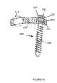
- FIG. 15is a diagrammatic representation of another embodiment of a bone screw and end plate
- FIG. 16is a diagrammatic representation of one embodiment of an attachment member coupled to a plate
- FIG. 17is a diagrammatic representation of an end view of another embodiment of a plate.
- FIGS. 18A and 18Bare diagrammatic representations of embodiments of channels in a plate.
- FIG. 19is a diagrammatic representation of another embodiment of a spinal implant.
- FIGURESPreferred embodiments of the invention are illustrated in the FIGURES, like numerals being used to refer to like and corresponding parts of the various drawings.
- Embodiments of the present inventionprovide systems and methods for spinal stabilization.
- a plate attached to one or more vertebraecan prevent expulsion of an interbody device from a disc space.
- the plate and interbody devicecan be coupled by an attachment member.
- the attachment memberis coupled to the plate and includes a portion inserted in a threaded or non-threaded cavity of the interbody.
- the coupling between the plate and attachment memberallows rotation in three dimensions thereby allowing the plate to rotate relative to the interbody. This allows the plate to be better positioned for attachment to the spine during an operation.
- the attachment member and interbodycan be shaped so that the interbody is a specified distance away from the plate and consequently a desired distance into the disc space.
- FIG. 1is a diagrammatic representation of a side view of one embodiment of an implant 100 .
- Implant 100can include a plate 106 coupled to an interbody device 110 by an attachment member 115 .
- Implant 100can comprise any biocompatible material, including, but not limited to, titanium, titanium alloy, stainless steel, ceramic material, bone, polymers or combinations thereof. Various portions of implant 100 may be made of different materials and may be radiolucent.
- interbody device 110can be formed of PEEK
- plate 105is formed of titanium.
- both interbody device 110 and plate 105can both be made of PEEK.
- implant 100is formed of a titanium and aluminum alloy, such as Ti6Al4V-Eli.
- Plate 105can be flat, curved, or have any suitable form factor for spinal surgery.
- plate 105includes holes 120 for fasteners 125 that allow plate 105 to be attached to the appropriate vertebrae.
- fastenersinclude, but are not limited to, bone screws, nails, rivets, trocars, pins, barbs or other threaded or non-threaded member which is securable within or to bone.
- bone screwscan be attached to plate 105 in a manner that allows for polyaxial rotation prior to attachment to the bone.
- One example of a mechanism for attaching a plate to vertebrae that allows for polyaxial rotation of bone screwsis described in U.S.
- Plate 105may be attached to the spine with any number of fasteners.
- Interbody device 110may have a variety of different form factors and sizes.
- face 127may be angled relative to face 130 so that a desired angle of lordosis is achieved when implant 100 is in place.
- the outer faces of interbody device 110may be sloped to allow an anterior side height to differ from a posterior side height.
- faces 127 and 130may be curved. This curvature may allow outer faces 127 and 130 to substantially conform to the shapes of vertebral surfaces, particularly the anatomical domes of the respective vertebra.
- outer faces 127 and 130can be coated with titanium plasma spray, bone morpohogenic proteins, hydroxyapatite and/or other coatings.
- outer faces 127 and 130may be roughed by processes such as, but not limited to, chemical etching, surface abrading, shot peening, electric discharge roughening or embedding particles in the surface.
- Interbody device 110may include a number of protrusions 135 that can extend into adjacent vertebrae to better hold interbody device 110 .
- Protrusions 135can be arranged in rows of teeth, in radial rows or other arrangements with any number of protrusions.
- Protrusions 135can extend any distance, but preferably are at least 0.2 mm to 1 mm long.
- protrusions 135may be arranged as rows of teeth configured to “bite” into the vertebrae as interbody device 110 is implanted. In the example shown, the teeth are angled to prevent interbody device 110 from shifting to the right, thereby reducing movement away from plate 105 .
- interbody device 110can include a cavity 140 to receive attachment member 115 .
- Cavity 140 and attachment member 115can be configured so that interbody device 110 is a desired minimum distance from plate 105 . This allows the depth of insertion of interbody device 110 into the space between the vertebrae to be controlled (i.e., a greater distance between interbody device 110 and plate 105 will lead to a greater depth of insertion).
- cavity 140can be a counterbore into which attachment member 115 inserts without further attachment. In this case cavity 140 and the portion of attachment member inserted in cavity 140 can be unthreaded. If additional attachment is desired to prevent interbody device 110 from detaching from attachment member 115 , cavity 140 and attachment member 115 can be threaded as shown in FIG. 1 .
- cavity 140can include a threaded portion and a countersunk portion 145 .
- Surface 150can abut shoulder 155 to limit the depth of insertion of attachment member 115 .
- the depth of countersunk portion 145 and the distance between plate 105 and shoulder 155can be configured to limit the closeness of interbody device 110 and plate 105 and thereby control the minimum insertion distance of interbody 110 into the disc space.
- Attachment member 115 and cavity 140can be otherwise shaped to control the distance between interbody device 110 and plate 105 .
- FIGS. 2A-2Dvarious embodiments of attachment member 115 inserted in cavity 140 are shown.
- interbody device 110includes a countersunk portion 145 .
- Attachment membercan include a straight shoulder 155 that abuts the surface 150 of countersunk portion 145 .
- shoulder 155can be beveled, curved or otherwise shaped. Based on the depth of the countersink, and length 160 from plate 105 to shoulder 155 , the closeness of interbody device 110 to plate 105 can be controlled.
- attachment member 115includes a tapered threaded portion and interbody device 110 a corresponding tapered cavity 140 .
- the taper of attachment member 115 and cavity 140can determine how far attachment member 115 can be threaded into interbody device 110 . This, combined with length 160 to the tapered threading, limits how close interbody device 110 is to plate 105 .
- attachment member 115can include protrusion 170 that abuts the outer surface 175 of interbody device 110 (or a counterbore surface or other surface) to limit how far attachment member 115 can be threaded into interbody device 110 .
- the length 160 from plate 105 to the surface of protrusion 170 that abuts interbody device 110determines the distance between plate 105 and interbody device 110 .
- cavity 140is simply a counterbore with unthreaded sides.
- Attachment member 115also has unthreaded surfaces and simply abuts a surface of cavity 140 .
- the closeness of interbody device 110 to plate 105is limited by the length 160 of attachment member 115 and the depth of cavity 140 .
- attachment member 115 and interbody device 110can be shaped so that interbody device 110 is a selected distance from plate 105 .
- Surgical kits for implant 100can include any number of plates 105 , attachment members 115 and interbody devices 110 .
- a surgical kit for implant 100can include a number of small, medium and large interbody devices 110 that can vary in length, width, height or other dimension.
- interbody devices 110 with various slopescan be provided. This allows the surgeon to form implant 100 to have the appropriate sized interbody device 110 for a patient and to achieve desired lordotic adjustment.
- the interbodies and attachment memberscan be color coded and/or include other indicia to indicate size, slope, offsets and other parameters.
- various interbody devices 110 and attachment members 115can be provided to allow a surgeon to select the depth of insertion of a selected interbody device 110 relative to plate 105 .
- a surgical kitcan contain an interbody device 110 with a set countersink and a variety of attachment members 115 that have different offsets to a stop or shoulder. By selection of the appropriate attachment member, the surgeon can select how far into the disc space interbody device 110 is implanted.
- a single attachment member and various interbody devices 110can be provided.
- the various interbody devices 110can have countersinks of various depths to achieve a desired distance between a selected interbody device 110 and plate 105 .
- the cavities to receive the attachment memberscan be located differently on different interbodies. This allows the surgeon to select whether the interbody device will be inserted at a particular angle to the spine (e.g., from an anterior or lateral approach).
- multiple interbodies and attachment membercan be provided.
- FIG. 3is a diagrammatic representation illustrating an oblique view of one embodiment of implant 100 , emphasizing surface 127 of interbody device 110 and showing features such as protrusions 135 , discussed above. While shown as having a generally oblong shape, interbody device 110 can have a rectangular, square, circular or other shape. FIG. 3 further illustrates that interbody device 110 can include channels, such as channel 180 , running from surface 127 to surface 130 . While shown as having a substantial area compared to the overall area of interbody device 110 the channels 180 can be relatively small and more numerous, not present at all or otherwise configured. The channels 180 can allow bone to pass as bone growth occurs, thereby allowing the vertebrae to fuse together. Additionally, the 180 channels can be packed with bone growth material.
- the bone growth materialcan include autograft bone (such as bone from the patient's lilac crest), allograft bone, synthetic bone growth material or combinations thereof.
- FIG. 3further illustrates holes 120 for fasteners to attach plate 105 to the adjacent vertebrae and hole 195 for attachment member 115 .
- attachment member 115 and fasteners 125can be coupled to plate 105 in a manner that allows attachment member 115 and fasteners 125 to rotate in multiple directions relative to plate 105 .
- FIG. 4is a diagrammatic representation of a partially exploded view of one embodiment of implant 100 including plate 105 , interbody device 110 and attachment member 115 .
- FIG. 4emphasizes surface 175 of interbody device 110 having an opening to cavity 140 .
- Cavity 140can be a counterbore.
- a portion of attachment member 115can be inserted in the counterbore and abut the surface of countersunk portion 145 to limit how far attachment member 115 is inserted into interbody device 110 .
- both cavity 140 and the corresponding portion of attachment member 115are unthreaded.
- interbody device 110can be attached to plate 105 in a manner that limits the closeness of plate 105 to interbody device 110 .
- interbody device 110 and attachment member 115can be shaped to achieve a gap having a particular minimum size between interbody device 110 and plate 105 .
- interbody device 110includes a female threaded cavity with a countersunk portion.
- Attachment member 115can include a threaded portion and a shoulder that abuts the surface of the countersink. Attachment member 115 can be in a fixed position relative to plate 105 , integrated with plate 105 or otherwise coupled to plate 105 .
- attachment member 115can be attached to plate 105 in a manner that allows movement between attachment member 115 and plate 105 .
- attachment member 115is attached in a manner that allows plate 105 to rotate in three directions relative to interbody device 110 prior to attaching plate 105 to the vertebrae.
- FIGS. 5-18Various, non-limiting examples of allowing movement of plate 105 relative to interbody device 110 are discussed below in conjunction with FIGS. 5-18 .
- FIG. 5is a diagrammatic representation of an end view of one embodiment of implant 100 , including plate 105 , interbody device 110 and attachment member 115 .
- FIG. 5represents an anterior view.
- Plate 105includes fastener holes 120 shaped to receive the heads of fasteners 125 and attachment member hole 195 to receive a head of attachment member 115 .
- holes 120 and 195can be the same size and the head of attachment member 115 can be similar to the heads of fasteners 125 .
- Rings 200can be disposed in holes 120 and 195 . While all rings 200 are shown as being identical in FIG. 5 , the rings may have different dimensions.
- rings 200include a gap, or other feature that allows rings 200 to contract under pressure.
- rings 200allow fasteners 125 and attachment member 115 to be rotated to a variety of orientations relative to plate 105 , as discussed below in conjunction with FIGS. 6-16 .
- Plate 105can also include holes 205 that can strengthen plate 105 under compressive loads.
- attachment member hole 195In the example of FIG. 5 , only one attachment member hole 195 is shown. However, other embodiments may include multiple attachment member holes 195 at different locations to allow a surgeon to select various positions of interbody device 110 relative to plate 105 . Furthermore, while four fastener holes 120 are shown, other embodiments may include more or less fasteners.
- FIG. 6depicts a cross-sectional view of an embodiment of one of the holes 120 (also shown in FIG. 5 ) in which screw 125 is disposed.
- Hole 120is preferably substantially spherical in shape so that a head 232 of screw 125 may be rotated and moved to various positions within hole 120 .
- Ring 200is preferably sized to fit into hole 120 between plate 105 and head 232 .
- the outer surface of ring 200is preferably curved to permit movement of the ring within hole 120 .
- the combination of ring 200 and hole 120is like that of a ball and socket since ring 200 may be rotated both horizontally and vertically in clockwise and counterclockwise directions within hole 120 . Ring 200 may also be rotated in directions that are angled away from the horizontal and vertical directions.
- ring 200at least partially surrounds head 232 of screw 125 which is positioned within hole 120 .
- a shank 234 of bone screw 125preferably has threading 236 to allow the screw to be inserted into a bone when it is rotated in a clockwise direction.
- Head 232preferably includes a cavity 242 that extends from the top of the head to an inner portion of the head. Cavity 242 may be shaped to receive the end of any fastening device e.g., a socket wrench that may be used to turn screw 125 .
- Screw 125may be simultaneously screwed into a bone and moved to its desired position.
- the inner surface of ring 200 and the outer surface of head 232are preferably tapered and shaped to mate with each other.
- the bottom portion of head 232is preferably smaller than the upper portion of ring 200 .
- head 232preferably applies a radial force to ring 200 , thereby causing the ring to expand within the hole and increase the size of the ring's gap.
- An interference fitmay form between screw head 232 , ring 200 , and plate 105 in which these elements fit so tightly together that they obstruct the movements of each other.
- the hoop stress of ring 200 on head 232may fixedly attach screw 125 to plate 105 .
- screw head 232 and ring 200may be positioned within hole 120 such that their left sides are at a higher elevation than their right sides.
- FIG. 6shows that positioning screw head 232 in this configuration may result in a centerline 228 of shank 234 being obliquely angulated with respect to plate 105 .
- centerline 238may be positioned where it is at an angle ranging from 0 to 15 degrees with respect to an imaginary axis 240 which is perpendicular to plate 105
- FIG. 6demonstrates shank 234 of screw 125 being angled to the left of imaginary axis 240 while FIG. 7 demonstrates shank 234 being angled to the right of imaginary axis 240 .
- Screw 125is not limited to these positions and can be angled in various directions, such as into the page.
- FIGS. 8 and 9depict different embodiments of end plate 105 with fasteners inserted
- FIG. 8shows that screws 125 may be positioned within holes 120 such that they extend in converging directions with respect to each other.
- the screws 125 depicted in FIG. 9are shown as being positioned such that their shanks 234 extend in diverging directions with respect to each other. Screws 125 may be moved to such positions as described above. Since bone screws 125 may be placed in diverging or converging directions through holes 120 at both ends of plate 105 , screw backout may be greatly reduced. Further, the use of rings 200 to fixedly attach screws 125 to plate 105 may prevent damage to tissue structures by any screws that are able to escape from the bone.
- Rings 200preferably do not extend above the upper surface of plate 105 , and thus advantageously do not contact tissue structures.
- Screw 125may be placed in a uni-cortical position within the bone since the problem of screw backout is greatly reduced by the diverging or converging screw configurations.
- FIG. 10A side view of another embodiment of a spinal plate 105 and fasteners is shown in FIG. 10 .
- This embodimentincludes a bone screw 125 and a ring 200 .
- Plate 105may be used to stabilize a bony structure such as the spine to facilitate a bone fusion (e.g., a spinal fusion).
- the bone screw 125may be used to connect plate 105 to a bone such as a vertebra.
- Ring 200preferably fixes bone screw 125 to plate 105 at a selected angle that depends upon the patients anatomy.
- each hole 120preferably has a curvate inner surface 313 for engaging the outer surface 323 of ring 200 .
- the inner surface 313preferably has the shape of a portion of an outer surface of a sphere.
- Hole 120has a width that is defined across the inner surface 313 of the borehole.
- the width of the boreholemay vary in a direction axially through the borehole.
- the width of the holespreferably increases from a surface of the plate 105 to about the middle of the plate 105 .
- the width of the hole 120preferably decreases from about the middle of the plate 105 to an opposite surface of the plate 105 such that the hole has a maximum width near the midpoint between the surfaces.
- the outer surface 323 of ring 200is preferably curvate for engaging the inner surface 313 of the borehole.
- the shape of surfaces 323 and 313preferably allow ring 200 to swivel within the borehole.
- the swiveling actionmay be similar to that of a ball and socket joint.
- the ring 200preferably surrounds at least a portion of the head 325 of a bone screw 125 .
- the enlarged end 327 disposed on head 325is optional and need not be included if it inhibits angulation of the bone screw 125 .
- the swiveling of the ring 200 within the boreholepreferably enables the shank 335 of the bone screw 320 to rotate in a substantially conical range of motion.
- the head 325is preferably movable within the borehole, and the shank 335 is adjustably positionable at a plurality of angles substantially oblique to the plate 105 .
- the surfaces 323 and 313are preferably shaped to provide a conical range of motion to the shank 335 that is within a preferred range of angles.
- the head 325is preferably movable within the borehole such that the shank 335 can be positioned at a selected angle relative to an imaginary axis running perpendicular to the plate 105 proximate borehole 120 .
- the selected angleis preferably less than about 45 degrees, more preferably less than about 30 degrees, and more preferably still less than about 15 degrees.
- Ring 200preferably has an outer width that is less than or about equal to the width of hole 120 at a location between the surfaces of plate 105 . In this manner, ring 200 may be positioned within hole 120 proximate the middle of the hole to enable the bone screw 125 to extend substantially perpendicularly from the bone plate 105 . Prior to surgery, rings 200 are preferably pre-positioned within holes 120 of plate 105 . “Pre-positioned” is taken to mean that the rings are capable of swiveling within the borehole but are preferably inhibited from falling out of the borehole because of the reduced width of the borehole proximate the upper and lower surfaces.
- the width of the borehole proximate the upper and lower surfaces of plate 105is preferably less than or about equal to the outer width of the ring 200 to inhibit the ring from failing out of the borehole.
- the surgeonmay use a plate 105 having rings 200 pre-positioned within the holes 120 such that the rings 200 will not fall into the surgical wound when implant 100 is installed.
- the rings 200can be manually positioned within holes 120 during surgery.
- Ring 200preferably includes one or more slots or gaps.
- the slotpreferably allows the ring 200 to be contracted or expanded. Contraction of ring 200 may allow the ring 200 to be positioned within the borehole during surgery. Once positioned within the borehole the ring 200 preferably expands and is inhibited from falling out of the borehole.
- Ring 200is preferably capable of being swiveled such that one portion of the ring 200 is adjacent to one surface of plate 105 while another portion of the ring 200 lies adjacent to the opposite surface of plate 105 .
- Ring 200is preferably sufficiently thin to allow it to reside within the borehole without extending from the borehole beyond the surfaces of plate 105 .
- the ring 200 and screw head 325remain within the hole 120 to minimize the profile of implant 100 .
- the bone screw 125may be capable of being angulated relative to the plate 105 such that ring 200 extends from the hole 120 beyond a surface of the plate 105 .
- the head 325is preferably screwed into ring 200 to create a fixed connection between bone screw 125 and plate 105 at a selected angle.
- screw head 325preferably contains head threading 321 on its outer surface that is complementary to ring threading 319 contained on the inner surface of ring 200 .
- the head threading 321preferably mates with the ring threading 319 to enhance the connection between the bone screw 125 and the ring 200 .
- the head 325preferably has a cavity 342 formed on its upper surface for receiving a driving tool such as a screw driver or an alien wrench.
- the head threading 321 on the head 325 and the ring threading 319 on the inner surface of ring 200is preferably substantially fine relative to the threading 336 on bone screw 125 . That is, the pitch of the head threading 321 and ring threading 319 is preferably smaller than that on bone screw 125 .
- the ring threading 319preferably has multiple starts to facilitate connection of the bone screw and the ring. In one embodiment, the ring threading 319 has a double start such that the head can be started into the ring threading at either one of two orientations offset by 180 degrees. In another embodiment, the ring threading has a triple start such that the head can be started into the ring threading at any one of three orientations offset by 420 degrees.
- the ring threading 319 and head threading 321are preferably pitched to a substantially similar degree to the threading 336 on the bone screw 320 .
- the ring threading 319 and head threading 321are pitched such that the head 325 causes expansion of the ring 200 while the bone screw 320 is being inserted into the bone.
- holesmay be drilled and tapped into the bones to which plate 105 is to be attached. Plate 105 may then be positioned adjacent to the bones.
- a ring 200may be positioned within the borehole.
- a bone screw 125may be positioned through ring 200 such that the head threading 321 of head 325 engages the ring threading 319 of ring 200 .
- the bone screw 125may then be rotated to insert the bone screw into the bone.
- the head threads and ring threadspreferably interact such that the head is moved into the ring. Movement of the head 325 into the ring 200 preferably causes the ring to expand such that the orientation of the bone screw 320 relative to the plate 105 is fixed.
- the ring threading and head threadingis pitched such the orientation of the bone screw 125 is fixed after plate 105 engages the bone.
- the bone screwsmay be used in pairs to prevent screw backout.
- the bone screwsare preferably positioned into the bone in substantially converging or substantially diverging directions relative to one another.
- the outer surface of the head 325is preferably tapered so that screwing the head into the ring causes a change in width (e.g., expansion) of the ring 200 to fix the bone screw 320 in position relative to the plate 105 .
- the inner surface of the ring 200may also be tapered to substantially match the taper on the outer surface of the head. At least a portion of the head 325 preferably has a width greater than the inner width of the ring 200 .
- the ring 200may contain a slot or gap as previously described to facilitate expansion of the ring against the inner surface 313 of the hole 120 .
- the slotis preferably widened as a result of force received from head 325 .
- the force exerted by head 325 against the inner surface of ring 200preferably presses the ring into a fixed engagement against inner surface 313 of hole 120 .
- ring 200may contain one or more partial slots 345 , as depicted in FIG. 12 .
- Each partial slot 345preferably extends from a top 347 or bottom 349 of ring 200 into the ring. Partial slots may extend up to about midpoint 348 of ring 200 .
- a plurality of slots 345may be oriented about the ring such that alternate slots extend from the top 347 and/or the bottom 349 of ring 200 , as depicted in FIG. 12 . These alternating partial slots preferably facilitate the expansion and contraction of ring 200 .
- FIGS. 13A and 13BCross-sectional views of two embodiments of ring 200 having threaded section 319 are shown in FIGS. 13A and 13B .
- the ringmay contain an inner surface that is tapered (as shown in FIG. 13A ) or that is substantially non-tapered (as shown in FIG. 13B ).
- Cross sectional views of two embodiments of screw 125are shown in FIGS. 14A and 14B .
- the head 325may have a substantially non-tapered outer surface 331 (as shown in FIG. 14A ) or a substantially tapered outer surface 331 (as shown in FIG. 14B ).
- each of the heads of the screws depicted in FIGS. 14A and 14Bmay be used in combination with either of the rings 200 depicted in FIGS. 13A and 13B .
- the head of the screwmay include an outer surface having a substantially non-tapered portion along with a tapered portion proximate its end for expanding the ring 200 .
- a “ring”is taken to mean any member capable of fitting between the inner surface 313 of a fastener hole and the bone screw 125 to connect the bone screw to the plate 105 .
- the ringis preferably substantially circular to surround head 325 , but the ring may instead have a non-circular shape.
- the ringmay be made of a number of biocompatible materials including metals, plastics, and composites.
- a stronger connection between the bone screw 125 and the plate 105may be formed by texturing either outer surface 331 of head 325 of bone screw 125 or inner surface 333 of ring 200 , as depicted in FIG. 15 .
- both surfacesare textured to inhibit movement of the bone screw with respect to the plate.
- outer surface 331 of head 325 and inner surface 333 of ring 200may be formed as relatively smooth surfaces. While the friction between these smooth surfaces tends to be sufficient to maintain bone screw 125 in a fixed position with respect to plate 105 , under stressful conditions the bone screw may be forced out of ring 200 .
- the coefficient of friction of the surfacemay be increased so that a large amount of force is needed to overcome the frictional connection between head 325 of bone screw 125 and ring 200 . This increase in friction between bone screw 125 and ring 200 may further inhibit screw backout from plate 105 .
- a number of textured surfacesmay be used to increase the coefficient of friction between ring 200 and head 325 of bone screw 125 .
- any process which transforms a relatively smooth surface into a roughened surface having an increased coefficient of frictionmay be used.
- Methods for forming a roughened surfaceinclude, but are not limited to: sanding, forming grooves within a surface, ball peening processes, electric discharge processes, and embedding of hard particles within a surface.
- a plurality of groovesmay be formed in outer surface 331 of head 325 of bone screw 125 or inner surface 333 of ring 200 .
- a plurality of groovesis formed in both outer surface 331 and inner surface 333 . While it is preferred that both outer surface 331 and the inner surface 333 be textured, texturing of only one of the surfaces may be sufficient to attain additional resistance to movement.
- the frictional surfacemay be created by an electrical discharge process.
- An electrical discharge processis based on the principle of removal of portions of a metal surface by spark discharges. Typically a spark is generated between the surface to be treated and an electrode by creating potential differential between the tool and the electrode. The spark produced tends to remove a portion of the surface disposed between the electrode and the surface.
- the electrodeis relatively small such that only small portions of the surface are removed.
- By moving the electrode about the surfacenumerous cavities may be formed within the surface. Typically these cavities are somewhat pyramidal in shape. Various patterns may be formed within the surface depending on how the electrode is positioned during the discharge. Electric discharge machines are well known in the art. A method for forming a frictional surface within a metal surface using an electric discharge process is described in U.S. Pat. No. 4,964,641 to Miesch et al. which is incorporated by reference as if set forth herein.
- a variety of patternsmay be formed using an electric discharge machine.
- a diamond pattern or a waffle patternis formed on either inner surface 333 of ring 200 or outer surface 331 of head 325 of bone screw 125 .
- inner surface 333 of ring 200 and/or outer surface 321 of head 325 of bone screw 125may be textured by the use of a shot peening process.
- a shot peening process for forming a textured surfaceis described in U.S. Pat. No. 5,526,664 to Vetter which is incorporated by reference as if set forth herein.
- a shot peening processinvolves propelling a stream of hardened balls, typically made of steel, at a relatively high velocity at a surface. To create a pattern upon an area of the surface the stream is typically moved about the surface. The speed by which the stream is moved about the surface tends to determine the type of textured surface formed.
- the streamis moved such that a pattern resulting in a textured surface having ridges and valleys is formed on inner surface 333 of ring 200 and outer surface 331 of head 325 of bone screw 125 .
- the ridges and valleysmay interact with each other to provide additional resistance to movement in either a longitudinal direction or a direction perpendicular to the longitudinal axis.
- the textured surfacemay be produced by embedding sharp hardened particles in the surface.
- a method for embedding sharp hardened particles in a metal surfaceis described in U.S. Pat. No. 4,768,787 to Shira which is incorporated by reference as if set forth herein.
- the method of Shirainvolves using a laser or other high energy source to heat the surface such that the surface melts in selected areas. Just before the molten area re-solidifies, a stream of abrasive particles is directed to the area. In this manner some of the particles tend to become embedded within the molten surface.
- the particlestypically have a number of sharp edges that protrude from the surface after the particles have been embedded within the surface.
- outer surface 331 of head 325 of bone screw 125may be textured using a pattern of grooves.
- Inner surface of ring 200may be textured using an electrical discharge method. When coupled together the textured surfaces of bone screw 125 and ring 200 may interact with each other to provide additional resistance to movement in either a longitudinal direction or a direction perpendicular to the longitudinal axis.
- Textured surfacesmay also be formed on any of the other surfaces of the plate system. The formation of textured surfaces preferably increases the frictional resistance between the various components of the plate system.
- FIGS. 6-15generally describe embodiments of attaching bone screws 125 to plate 105
- attachment member 115can be similarly coupled to plate 105
- FIG. 16is a diagrammatic representation illustrating that similar attachment mechanisms can be used to couple attachment member 115 to plate 105
- FIG. 16depicts a cross-sectional view of an embodiment of hole 195 in which attachment member 115 is disposed.
- Hole 195is preferably substantially spherical in shape so that a head 350 of attachment member 115 may be rotated and moved to various positions within hole 195 .
- Ring 200is preferably sized to fit into hole 195 between plate 105 and head 350 .
- the outer surface of ring 200is preferably curved to permit movement of the ring within hole 195 .
- ring 200is like that of a ball and socket since ring 200 may be rotated both horizontally and vertically in clockwise and counterclockwise directions within hole 195 . Ring 200 may also be rotated in directions that are angled away from the horizontal and vertical directions.
- ring 200at least partially surrounds head 350 of attachment member 115 which is positioned within hole 195 .
- a shank of attachment member 115preferably has threading 360 to allow attachment member 115 to screw into a corresponding cavity of interbody device 110 and a shoulder 155 to abut a countersunk surface 150 of the insert interbody (as shown in FIG. 1 ).
- Head 350preferably includes a cavity 365 that extends from the top of the head to an inner portion of the head. Cavity 365 may be shaped to receive the end of any fastening device e.g., a socket wrench that may be used to turn attachment member 115 .
- the inner surface of ring 200 and the outer surface of head 350are preferably tapered and shaped to mate with each other.
- the bottom portion of head 350is preferably smaller than the upper portion of ring 200 .
- head 350preferably applies a radial force to ring 200 , thereby causing the ring to expand within the hole and increase the size of the ring's gap.
- An interference fitmay form between head 350 , ring 200 , and plate 105 in which these elements fit so tightly together that they obstruct the movements of each other.
- the hoop stress of ring 200 on head 350may fixedly attach attachment member 115 to plate 105 .
- Attachment member 115shows that attachment member 115 may be obliquely angulated with respect to plate 105 .
- Attachment member 115may be positioned where it is at an angle ranging from 0 to 15 degrees or greater.
- the arrows of FIG. 16illustrate that attachment member 115 can rotate clockwise and counter clockwise and angle to the left and right. Additionally, attachment member 115 can angle into or out of the paper. Thus, attachment member 115 can rotate in three dimensions relative to plate 105 . While a particular embodiment of attachment member 115 and ring 200 are illustrated for coupling attachment member 115 to plate 105 , other embodiments can be used including, but not limited to, those described in conjunction with FIGS. 6-15 .
- FIG. 17illustrates another embodiment of a system that allows attachment member 115 to move relative to plate 105 .
- plateincludes a channel 370 into which a head portion of attachment member 115 fits.
- Channel 370allows attachment member 115 to slide up and down.
- attachment member 115can be locked in place once a selected position is achieved.
- channel 370is shown as an elongated slot, channel 370 can have a variety of other shapes including, but not limited to, an “X” shape, “H” shape, “I” shape, “T” shape or other shape.
- attachment member 115can be placed in channel 370 by angling attachment member 115 past a particular angle, through a keyhole feature or other mechanism.
- FIGS. 18A and 18Bare diagrammatic representations of example cross sections of channel 370 that allow attachment member 115 to be angled.
- head 350is captured by the sidewalls of channel 370 in a manner that prevents attachment member 115 from falling out of channel 370 , but still allows rotation. While head 350 is shown as flat, head 350 can be spherical or have another shape. Additionally, head 350 can include features that allow attachment member 115 to be rotated by a tool, such as an allen wrench, screwdriver or other tool.
- a toolsuch as an allen wrench, screwdriver or other tool.
- head 350is generally spherical with a flange 375 or other feature that is captured by the sidewalls of channel 370 in a manner that allows attachment member 115 to be angled relative to plate 105 .
- Head 350can include features that allow attachment member 115 to be rotated by a tool, such as an allen wrench, screwdriver or other tool.
- attachment membercan rotate clockwise/counterclockwise, left and right (as shown) and into and out of the page.
- FIG. 19is a diagrammatic representation illustrating an oblique view of another embodiment of implant 100 , emphasizing surface 127 of interbody device 110 and showing features such as protrusions 135 , discussed above. While shown as having a generally oblong shape, interbody device 110 can have a rectangular, square, circular or other shape. FIG. 19 further illustrates that interbody device 110 can include channels, such as channel 180 , running from surface 127 to surface 130 . While shown as having a substantial area compared to the overall area of interbody device 110 the channels can be relatively small and more numerous, not present at all or otherwise configured. The channels can allow bone to pass as bone growth occurs, thereby allowing the vertebrae to fuse together. Additionally, the channels can be packed with bone growth material.
- the bone growth materialcan include autograft bone (such as bone from the patient's iliac crest), allograft bone, synthetic bone growth material or combinations thereof.
- FIG. 19further illustrates holes 120 for fasteners to attach plate 105 to a single vertebra and hole 195 for attachment member 115 .
- attachment member 115 and fasteners 125can be coupled to plate 105 in a manner that allows attachment member 115 and fasteners 125 to rotate in multiple directions relative to plate 105 .
- the surgeoncan assemble implant 100 external to the patient. Assembly can include selecting one or more of the appropriate plate 105 , interbody device 110 and attachment member 115 to create an appropriately sized implant 100 . In assembling implant 100 , the surgeon can insert ring 200 and attachment member 115 into hole 195 . The surgeon can then attach interbody device 110 to attachment member 115 . The surgeon can then insert implant 100 into the body such that plate 105 abuts the one or more vertebrae and interbody device 110 is partially or fully inserted into the disc space.
- interbody device 110When interbody device 110 is in place, the surgeon can rotate plate 105 relative interbody device 110 in multiple dimensions to better align plate 105 with the one or more vertebrae to which it will be attached. The surgeon can then fasten plate 105 to the one or more vertebrae with bone screws 125 or other fasteners.
- end plate 105is prepared for surgical implantation by pre-positioning of rings 200 within holes 120 and 195 .
- holesmay be drilled and tapped into the bones to which plate 105 is to be attached.
- Each of the screws 125may be screwed into the bone holes while they are being positioned within their corresponding holes 120 .
- Each pair of screws 125may be positioned so that shanks of the screws are at oblique angles relative to the plate.
- the insertion force of each screw 125 into each ring 200preferably causes the ring to exert a compressive force on the screw head, thereby fixably connecting the screws to plate 105 .
- implant 100is fully assembled external to the patient.
- the surgeon assembly plate 105 and attachment member 115external to the patient but not yet couple interbody device 110 to attachment member 115 .
- the surgeoncan position interbody device 110 in the disc space and then insert attachment member 115 into the cavity of interbody device 110 .
- Plate 105can then be positioned relative to the one or more vertebrae to which it will be attached.
- Bone screws 125can then fasten plate 105 in place.
- rings 200may be pre-positioned in holes 120 and 195 .
- plate 105can rotate in multiple directions relative to interbody device 110 , a surgeon can better position plate 105 relative to the spine. This can eliminate or substantially reduce the need to physically bend plate 105 to abut the vertebrae. Furthermore, the use of plate 105 prevents expulsion of interbody device 110 without the need for posterior side bone screws. Moreover, a surgeon can select the appropriate depth of insertion of interbody device 110 by selecting the appropriate attachment member 115 and/or interbody device 110 .
Landscapes
- Health & Medical Sciences (AREA)
- Orthopedic Medicine & Surgery (AREA)
- Neurology (AREA)
- Engineering & Computer Science (AREA)
- Biomedical Technology (AREA)
- Life Sciences & Earth Sciences (AREA)
- General Health & Medical Sciences (AREA)
- Veterinary Medicine (AREA)
- Surgery (AREA)
- Heart & Thoracic Surgery (AREA)
- Public Health (AREA)
- Animal Behavior & Ethology (AREA)
- Molecular Biology (AREA)
- Medical Informatics (AREA)
- Nuclear Medicine, Radiotherapy & Molecular Imaging (AREA)
- Cardiology (AREA)
- Oral & Maxillofacial Surgery (AREA)
- Transplantation (AREA)
- Vascular Medicine (AREA)
- Prostheses (AREA)
Abstract
Description
Claims (46)
Priority Applications (1)
| Application Number | Priority Date | Filing Date | Title |
|---|---|---|---|
| US11/756,483US8216312B2 (en) | 2007-05-31 | 2007-05-31 | Spinal interbody system and method |
Applications Claiming Priority (1)
| Application Number | Priority Date | Filing Date | Title |
|---|---|---|---|
| US11/756,483US8216312B2 (en) | 2007-05-31 | 2007-05-31 | Spinal interbody system and method |
Publications (2)
| Publication Number | Publication Date |
|---|---|
| US20080300634A1 US20080300634A1 (en) | 2008-12-04 |
| US8216312B2true US8216312B2 (en) | 2012-07-10 |
Family
ID=40089113
Family Applications (1)
| Application Number | Title | Priority Date | Filing Date |
|---|---|---|---|
| US11/756,483Active2029-06-13US8216312B2 (en) | 2007-05-31 | 2007-05-31 | Spinal interbody system and method |
Country Status (1)
| Country | Link |
|---|---|
| US (1) | US8216312B2 (en) |
Cited By (96)
| Publication number | Priority date | Publication date | Assignee | Title |
|---|---|---|---|---|
| US20110224793A1 (en)* | 2008-04-01 | 2011-09-15 | Fortin Frederic | Base Piece That Can Be Adjusted Prior To Its Attachment, And Can Be Easily Incorporated Into A Device Replacing A Corpus Vertebrae |
| US20120172989A1 (en)* | 2009-04-27 | 2012-07-05 | Mccarthy Kevin | Vertebral osteosynthetis equipment |
| US20120259363A1 (en)* | 2011-04-08 | 2012-10-11 | Kyphon Sarl | Viscoelastic lumbar-sacral implant |
| US8343219B2 (en) | 2007-06-08 | 2013-01-01 | Ldr Medical | Intersomatic cage, intervertebral prosthesis, anchoring device and implantation instruments |
| US20130238095A1 (en)* | 2012-03-06 | 2013-09-12 | Nicholas Pavento | Nubbed Plate |
| US20130325071A1 (en)* | 2012-05-30 | 2013-12-05 | Marcin Niemiec | Aligning Vertebral Bodies |
| US20130345814A1 (en)* | 2011-11-17 | 2013-12-26 | Lanx, Inc. | Modular Anchor Bone Fusion Cage |
| WO2014059072A1 (en)* | 2012-10-11 | 2014-04-17 | Rhausler, Inc. | Bone plate and fusion cage interface |
| DE102013202211A1 (en)* | 2013-02-11 | 2014-08-14 | Rita Leibinger GmbH & Co. KG | Canines cervical implant |
| US20150005879A1 (en)* | 2013-06-28 | 2015-01-01 | Bacem Georges | Spinal Alignment Clip |
| US20150025635A1 (en)* | 2013-07-17 | 2015-01-22 | Aesculap Implant Systems, Llc | Spinal interbody device, system and method |
| US20150032220A1 (en)* | 2012-10-19 | 2015-01-29 | Tyber Medical Llc | Wedge Osteotomy Device and Method Of Use |
| US20150100126A1 (en)* | 2013-10-07 | 2015-04-09 | Warsaw Orthopedic, Inc. | Spinal implant system and method |
| US20150119992A1 (en)* | 2010-02-01 | 2015-04-30 | X-Spine Systems, Inc. | Spinal implant co-insertion system and method |
| US9039774B2 (en) | 2012-02-24 | 2015-05-26 | Ldr Medical | Anchoring device and system for an intervertebral implant, intervertebral implant and implantation instrument |
| US9044337B2 (en) | 2009-12-31 | 2015-06-02 | Ldr Medical | Anchoring device and system for an intervertebral implant, intervertebral implant and implantation instrument |
| US9078765B2 (en) | 2001-07-13 | 2015-07-14 | Ldr Medical | Vertebral cage device with modular fixation |
| US9198768B1 (en)* | 2014-05-07 | 2015-12-01 | Perumala Corporation | Enhanced artificial disk |
| US9326861B2 (en) | 2012-08-03 | 2016-05-03 | Globus Medical, Inc. | Stabilizing joints |
| US9345517B2 (en)* | 2008-02-02 | 2016-05-24 | Globus Medical, Inc. | Pedicle screw having a removable rod coupling |
| CN105596073A (en)* | 2016-02-01 | 2016-05-25 | 郑明辉 | Intervertebral securing device and intervertebral securing system |
| US20160151167A1 (en)* | 2014-12-01 | 2016-06-02 | Dae Jean JO | Intervertebral cage for spinal implant |
| US9358127B2 (en) | 2008-09-02 | 2016-06-07 | Globus Medical, Inc. | Intervertebral fusion implant |
| US9387087B2 (en) | 2012-10-19 | 2016-07-12 | Tyber Medical Llc | Orthopedic systems for spine and tracking control |
| US9439773B2 (en) | 2014-05-07 | 2016-09-13 | Perumala Corporation | Enhanced artificial disk |
| US9463091B2 (en) | 2009-09-17 | 2016-10-11 | Ldr Medical | Intervertebral implant having extendable bone fixation members |
| US9486327B2 (en) | 2014-05-15 | 2016-11-08 | Globus Medical, Inc. | Standalone interbody implants |
| US9504584B1 (en) | 2011-01-28 | 2016-11-29 | Nuvasive, Inc. | Spinal fusion implant and related methods |
| US9526620B2 (en) | 2009-03-30 | 2016-12-27 | DePuy Synthes Products, Inc. | Zero profile spinal fusion cage |
| US9545320B2 (en) | 2014-05-15 | 2017-01-17 | Globus Medical, Inc. | Standalone interbody implants |
| USD779065S1 (en) | 2014-10-08 | 2017-02-14 | Nuvasive, Inc. | Anterior cervical bone plate |
| US9597194B2 (en) | 2005-09-23 | 2017-03-21 | Ldr Medical | Intervertebral disc prosthesis |
| US9615936B2 (en) | 2009-06-04 | 2017-04-11 | Globus Medical, Inc. | Intervertebral fusion implant |
| US9675389B2 (en) | 2009-12-07 | 2017-06-13 | Samy Abdou | Devices and methods for minimally invasive spinal stabilization and instrumentation |
| US9687354B2 (en) | 2008-03-26 | 2017-06-27 | DePuy Synthes Products, Inc. | Posterior intervertebral disc inserter and expansion techniques |
| US9713535B2 (en) | 2006-02-15 | 2017-07-25 | Ldr Medical | Transforaminal intersomatic cage for an intervertebral fusion graft and an instrument for implanting the cage |
| US9724207B2 (en) | 2003-02-14 | 2017-08-08 | DePuy Synthes Products, Inc. | In-situ formed intervertebral fusion device and method |
| US9757246B1 (en)* | 2009-04-16 | 2017-09-12 | Nuvasive, Inc. | Methods and apparatus for performing spine surgery |
| US9877842B2 (en) | 2014-01-30 | 2018-01-30 | Ldr Medical | Anchoring device for a spinal implant, spinal implant and implantation instrumentation |
| US9895237B2 (en) | 2010-04-08 | 2018-02-20 | Globus Medical, Inc. | Intervertebral implant |
| US9937050B2 (en) | 2013-05-16 | 2018-04-10 | Ldr Medical | Vertebral implant, vertebral fastening device of the implant and implant instrumentation |
| US9949769B2 (en) | 2004-03-06 | 2018-04-24 | DePuy Synthes Products, Inc. | Dynamized interspinal implant |
| US9968461B2 (en) | 2014-05-15 | 2018-05-15 | Globus Medical, Inc. | Standalone interbody implants |
| US9993349B2 (en) | 2002-06-27 | 2018-06-12 | DePuy Synthes Products, Inc. | Intervertebral disc |
| US20180296348A1 (en)* | 2015-10-13 | 2018-10-18 | Cg Bio Co., Ltd. | Cervical spine fixation apparatus |
| US10159582B2 (en) | 2011-09-16 | 2018-12-25 | DePuy Synthes Products, Inc. | Removable, bone-securing cover plate for intervertebral fusion cage |
| US10182921B2 (en) | 2012-11-09 | 2019-01-22 | DePuy Synthes Products, Inc. | Interbody device with opening to allow packing graft and other biologics |
| US10201433B2 (en) | 2012-10-19 | 2019-02-12 | Tyber Medical Llc | System and method for correcting scoliosis |
| US10206787B2 (en) | 2006-12-22 | 2019-02-19 | Medos International Sarl | Composite vertebral spacers and instrument |
| US20190133777A1 (en)* | 2009-02-25 | 2019-05-09 | Spinewelding Ag | Spine stabilization device, and method and kit for its implantation |
| US10327910B2 (en) | 2013-03-14 | 2019-06-25 | X-Spine Systems, Inc. | Spinal implant and assembly |
| US10335289B2 (en) | 2010-09-23 | 2019-07-02 | DePuy Synthes Products, Inc. | Stand alone intervertebral fusion device |
| US10369015B2 (en) | 2010-09-23 | 2019-08-06 | DePuy Synthes Products, Inc. | Implant inserter having a laterally-extending dovetail engagement feature |
| US10433974B2 (en) | 2003-06-30 | 2019-10-08 | DePuy Synthes Products, Inc. | Intervertebral implant with conformable endplate |
| US10478310B2 (en) | 2014-05-06 | 2019-11-19 | Ldr Medical, S.A.S. | Vertebral implant, device for vertebral attachment of the implant and instrumentation for implantation thereof |
| US10500062B2 (en) | 2009-12-10 | 2019-12-10 | DePuy Synthes Products, Inc. | Bellows-like expandable interbody fusion cage |
| US10548740B1 (en) | 2016-10-25 | 2020-02-04 | Samy Abdou | Devices and methods for vertebral bone realignment |
| US10575961B1 (en) | 2011-09-23 | 2020-03-03 | Samy Abdou | Spinal fixation devices and methods of use |
| US10624760B2 (en) | 2017-05-22 | 2020-04-21 | Warsaw Orthopedic, Inc. | Spinal implant system and method |
| US10695105B2 (en) | 2012-08-28 | 2020-06-30 | Samy Abdou | Spinal fixation devices and methods of use |
| US10842642B2 (en) | 2009-04-16 | 2020-11-24 | Nuvasive, Inc. | Methods and apparatus of performing spine surgery |
| US10857003B1 (en) | 2015-10-14 | 2020-12-08 | Samy Abdou | Devices and methods for vertebral stabilization |
| US10888433B2 (en) | 2016-12-14 | 2021-01-12 | DePuy Synthes Products, Inc. | Intervertebral implant inserter and related methods |
| US10918498B2 (en) | 2004-11-24 | 2021-02-16 | Samy Abdou | Devices and methods for inter-vertebral orthopedic device placement |
| US10940016B2 (en) | 2017-07-05 | 2021-03-09 | Medos International Sarl | Expandable intervertebral fusion cage |
| US10966840B2 (en) | 2010-06-24 | 2021-04-06 | DePuy Synthes Products, Inc. | Enhanced cage insertion assembly |
| US10973652B2 (en) | 2007-06-26 | 2021-04-13 | DePuy Synthes Products, Inc. | Highly lordosed fusion cage |
| US10973648B1 (en) | 2016-10-25 | 2021-04-13 | Samy Abdou | Devices and methods for vertebral bone realignment |
| US11006982B2 (en) | 2012-02-22 | 2021-05-18 | Samy Abdou | Spinous process fixation devices and methods of use |
| US11026726B2 (en) | 2012-06-29 | 2021-06-08 | K2M, Inc. | Minimal-profile anterior cervical plate and cage apparatus and method of using same |
| US11039865B2 (en) | 2018-03-02 | 2021-06-22 | Stryker European Operations Limited | Bone plates and associated screws |
| US11123117B1 (en)* | 2011-11-01 | 2021-09-21 | Nuvasive, Inc. | Surgical fixation system and related methods |
| US11160666B2 (en) | 2014-05-15 | 2021-11-02 | Globus Medical, Inc. | Laterally insertable intervertebral spinal implant |
| US11173040B2 (en) | 2012-10-22 | 2021-11-16 | Cogent Spine, LLC | Devices and methods for spinal stabilization and instrumentation |
| US11179248B2 (en) | 2018-10-02 | 2021-11-23 | Samy Abdou | Devices and methods for spinal implantation |
| US11273050B2 (en) | 2006-12-07 | 2022-03-15 | DePuy Synthes Products, Inc. | Intervertebral implant |
| US11344424B2 (en) | 2017-06-14 | 2022-05-31 | Medos International Sarl | Expandable intervertebral implant and related methods |
| US11426286B2 (en) | 2020-03-06 | 2022-08-30 | Eit Emerging Implant Technologies Gmbh | Expandable intervertebral implant |
| US11426290B2 (en) | 2015-03-06 | 2022-08-30 | DePuy Synthes Products, Inc. | Expandable intervertebral implant, system, kit and method |
| US11446156B2 (en) | 2018-10-25 | 2022-09-20 | Medos International Sarl | Expandable intervertebral implant, inserter instrument, and related methods |
| US11446155B2 (en) | 2017-05-08 | 2022-09-20 | Medos International Sarl | Expandable cage |
| US11452607B2 (en) | 2010-10-11 | 2022-09-27 | DePuy Synthes Products, Inc. | Expandable interspinous process spacer implant |
| US11497619B2 (en) | 2013-03-07 | 2022-11-15 | DePuy Synthes Products, Inc. | Intervertebral implant |
| US11510788B2 (en) | 2016-06-28 | 2022-11-29 | Eit Emerging Implant Technologies Gmbh | Expandable, angularly adjustable intervertebral cages |
| US11529241B2 (en) | 2010-09-23 | 2022-12-20 | DePuy Synthes Products, Inc. | Fusion cage with in-line single piece fixation |
| US11596523B2 (en) | 2016-06-28 | 2023-03-07 | Eit Emerging Implant Technologies Gmbh | Expandable and angularly adjustable articulating intervertebral cages |
| US11602438B2 (en) | 2008-04-05 | 2023-03-14 | DePuy Synthes Products, Inc. | Expandable intervertebral implant |
| US11654033B2 (en) | 2010-06-29 | 2023-05-23 | DePuy Synthes Products, Inc. | Distractible intervertebral implant |
| US11737881B2 (en) | 2008-01-17 | 2023-08-29 | DePuy Synthes Products, Inc. | Expandable intervertebral implant and associated method of manufacturing the same |
| US11752009B2 (en) | 2021-04-06 | 2023-09-12 | Medos International Sarl | Expandable intervertebral fusion cage |
| US11850160B2 (en) | 2021-03-26 | 2023-12-26 | Medos International Sarl | Expandable lordotic intervertebral fusion cage |
| US11911287B2 (en) | 2010-06-24 | 2024-02-27 | DePuy Synthes Products, Inc. | Lateral spondylolisthesis reduction cage |
| US11957598B2 (en) | 2004-02-04 | 2024-04-16 | Ldr Medical | Intervertebral disc prosthesis |
| USRE49973E1 (en) | 2013-02-28 | 2024-05-21 | DePuy Synthes Products, Inc. | Expandable intervertebral implant, system, kit and method |
| US12090064B2 (en) | 2022-03-01 | 2024-09-17 | Medos International Sarl | Stabilization members for expandable intervertebral implants, and related systems and methods |
| US12440346B2 (en) | 2023-03-31 | 2025-10-14 | DePuy Synthes Products, Inc. | Expandable intervertebral implant |
Families Citing this family (65)
| Publication number | Priority date | Publication date | Assignee | Title |
|---|---|---|---|---|
| FR2824261B1 (en) | 2001-05-04 | 2004-05-28 | Ldr Medical | INTERVERTEBRAL DISC PROSTHESIS AND IMPLEMENTATION METHOD AND TOOLS |
| FR2846550B1 (en) | 2002-11-05 | 2006-01-13 | Ldr Medical | INTERVERTEBRAL DISC PROSTHESIS |
| FR2865629B1 (en) | 2004-02-04 | 2007-01-26 | Ldr Medical | INTERVERTEBRAL DISC PROSTHESIS |
| FR2869528B1 (en) | 2004-04-28 | 2007-02-02 | Ldr Medical | INTERVERTEBRAL DISC PROSTHESIS |
| FR2879436B1 (en) | 2004-12-22 | 2007-03-09 | Ldr Medical | INTERVERTEBRAL DISC PROSTHESIS |
| US7220283B2 (en)* | 2005-01-24 | 2007-05-22 | Exactech, Inc. | Prosthesis including a mechanism for attaching a first component to a second component |
| FR2893838B1 (en) | 2005-11-30 | 2008-08-08 | Ldr Medical Soc Par Actions Si | PROSTHESIS OF INTERVERTEBRAL DISC AND INSTRUMENTATION OF INSERTION OF THE PROSTHESIS BETWEEN VERTEBRATES |
| US20070202186A1 (en) | 2006-02-22 | 2007-08-30 | Iscience Interventional Corporation | Apparatus and formulations for suprachoroidal drug delivery |
| US8465546B2 (en) | 2007-02-16 | 2013-06-18 | Ldr Medical | Intervertebral disc prosthesis insertion assemblies |
| US9295564B2 (en)* | 2007-10-19 | 2016-03-29 | Spinesmith Partners, L.P. | Fusion methods using autologous stem cells |
| WO2010107692A1 (en)* | 2009-03-16 | 2010-09-23 | Synthes Usa, Llc | System and method for stabilizing vertebrae in spine surgery through a lateral access channel |
| US8715326B2 (en)* | 2009-08-28 | 2014-05-06 | Competitive Global Medical, Llc | Distal interphalangeal fusion device and method of use |
| WO2011028306A1 (en)* | 2009-09-06 | 2011-03-10 | Cowan Jr John A | Locking spinal fusion device |
| KR101136427B1 (en)* | 2009-09-25 | 2012-04-20 | (주)엘앤케이바이오메드 | Cervical intervertebral fusion device |
| US8979927B2 (en)* | 2009-11-18 | 2015-03-17 | Innovasis, Inc. | Spinal implant with staples |
| US8425576B2 (en)* | 2010-01-26 | 2013-04-23 | Westmark Medical, Llc. | Bone screw retention mechanism |
| US8425569B2 (en)* | 2010-05-19 | 2013-04-23 | Transcorp, Inc. | Implantable vertebral frame systems and related methods for spinal repair |
| JP5996544B2 (en) | 2010-10-15 | 2016-09-21 | クリアサイド・バイオメディカル・インコーポレーテッドClearside Biomedical Incorporated | Eye access device |
| US8685067B2 (en) | 2010-12-21 | 2014-04-01 | Competitive Global Medical, Llc | Compression plate apparatus |
| US8852281B2 (en) | 2011-01-18 | 2014-10-07 | Globus Medical, Inc. | Artificial spinal disk prosthesis |
| FR2971139B1 (en)* | 2011-02-03 | 2013-02-15 | Medicrea Int | PLATE FOR THE OSTEOSYNTHESIS OF THE LOMBO-SACRED JOINT |
| CA2829565A1 (en)* | 2011-03-10 | 2012-09-13 | DePuy Synthes Products, LLC | Awl screw fixation members and related systems |
| US8425606B2 (en) | 2011-06-21 | 2013-04-23 | John A. Cowan | Method and implant device for grafting adjacent vertebral bodies |
| US9724132B2 (en) | 2011-08-31 | 2017-08-08 | DePuy Synthes Products, Inc. | Devices and methods for cervical lateral fixation |
| US20130072978A1 (en)* | 2011-09-16 | 2013-03-21 | Joshua M. AMMERMAN | Vertebral body replacement and cervical plate construction |
| US20140058446A1 (en)* | 2011-09-28 | 2014-02-27 | Avi Bernstein | Spinal implant system |
| US8852278B2 (en) | 2011-12-22 | 2014-10-07 | DePuy Synthes Products, LLC | Lateral cage with integrated plate |
| WO2013116452A2 (en)* | 2012-01-31 | 2013-08-08 | The University Of Toledo | Bioactive fusion device |
| US9750616B2 (en) | 2012-02-17 | 2017-09-05 | Spinal Elements, Inc. | Interbody fusion device |
| ES2628444T3 (en)* | 2012-02-17 | 2017-08-02 | Medacta International S.A. | Intervertebral implant with improved clamping system for the fixation plate |
| AU2013282268A1 (en)* | 2012-06-29 | 2015-01-22 | DePuy Synthes Products, LLC | Lateral insertion spinal implant |
| US10383737B2 (en)* | 2012-10-19 | 2019-08-20 | Tyber Medical, LLC | Anatomical wedge implant |
| CN103099662B (en)* | 2013-01-04 | 2015-08-12 | 朱悦 | The monolateral fixed system of a kind of anterior cervical vertebrae |
| US9107767B2 (en)* | 2013-01-16 | 2015-08-18 | DePuy Synthes Products, Inc. | Intervertebral cage with anterior fixation and stabilization |
| US9572680B2 (en) | 2013-01-25 | 2017-02-21 | K2M, Inc. | Spinal implants, spinal implant kits, and surgical methods |
| US10105239B2 (en)* | 2013-02-14 | 2018-10-23 | Globus Medical, Inc. | Devices and methods for correcting vertebral misalignment |
| JP6373878B2 (en) | 2013-02-14 | 2018-08-15 | メダクタ・インターナショナル・ソシエテ・アノニム | Intervertebral implant with improved fixation plate shape |
| CA2911290C (en) | 2013-05-03 | 2021-07-27 | Clearside Biomedical, Inc. | Apparatus and methods for ocular injection |
| CN105916458B (en)* | 2013-06-24 | 2019-09-27 | 托莱多大学 | Bioactive Fusion Devices |
| US9603718B2 (en)* | 2014-02-27 | 2017-03-28 | Alphatec Spine, Inc. | Spacer with temporary fixation plate |
| US10245080B2 (en)* | 2014-06-04 | 2019-04-02 | Mohammad Etminan | System for mounting of a cervical plate to a vertebra |
| KR101531171B1 (en)* | 2014-09-16 | 2015-06-25 | (주) 서한케어 | Intervertebral prosthesis |
| US9872711B2 (en)* | 2014-10-21 | 2018-01-23 | Warsaw Orthopedic. Inc. | Spinal implant system and method |
| CN104546095B (en)* | 2015-01-27 | 2017-05-24 | 赵建华 | Adaptive floating combined cervical interbody fusion cage |
| US10342678B2 (en) | 2015-02-02 | 2019-07-09 | Spinal Elements, Inc. | Interbody implant inserter |
| US9615931B2 (en)* | 2015-03-20 | 2017-04-11 | Globus Medical, Inc. | Surgical plate systems |
| US20200000595A1 (en) | 2016-06-07 | 2020-01-02 | HD LifeSciences LLC | High X-Ray Lucency Lattice Structures |
| US9918750B2 (en)* | 2016-08-04 | 2018-03-20 | Osseus Fusion Systems, Llc | Method, system, and apparatus for temporary anterior cervical plate fixation |
| US10973681B2 (en) | 2016-08-12 | 2021-04-13 | Clearside Biomedical, Inc. | Devices and methods for adjusting the insertion depth of a needle for medicament delivery |
| CN106618808B (en)* | 2016-11-30 | 2018-06-26 | 四川大学华西医院 | Half-incisura intervertebral fusion fixator |
| CA3061043A1 (en) | 2017-02-14 | 2018-08-23 | HD LifeSciences LLC | High x-ray lucency lattice structures and variably x-ray lucent markers |
| CA3058365A1 (en) | 2017-04-01 | 2018-10-04 | HD LifeSciences LLC | Three-dimensional lattice structures for implants |
| US10888430B2 (en)* | 2017-06-21 | 2021-01-12 | NVision Biomedical Technologies, LLC | Expandable/variable lordotic angle vertebral implant and reading system therefor |
| US11058552B2 (en)* | 2017-06-21 | 2021-07-13 | NVision Biomedical Technologies, LLC | Anterior lumbar interbody fusion cage and plate |
| CN108969163B (en)* | 2017-12-28 | 2021-06-25 | 浙江德康医疗器械有限公司 | A zero-notch fusion device |
| EP3826582A4 (en)* | 2018-07-26 | 2022-05-25 | Nanohive Medical LLC | DYNAMIC IMPLANT FIXATION PLATE |
| US11013616B2 (en)* | 2018-10-10 | 2021-05-25 | K2M, Inc. | Sagittal balance systems and methods of use thereof |
| US11497617B2 (en) | 2019-01-16 | 2022-11-15 | Nanohive Medical Llc | Variable depth implants |
| WO2020176514A1 (en)* | 2019-02-25 | 2020-09-03 | University Of Cincinnati | Method and device for endoscopic endonasal occipitocervical fusion |
| JP2022531020A (en) | 2019-05-07 | 2022-07-05 | スパイナル・エレメンツ・インコーポレーテッド | Neck plate and inserter |
| HUP1900374A1 (en)* | 2019-11-04 | 2021-05-28 | Bodon Gergely Dr | Stabilizing implant for cervical vertebrae and fusion cage belonging thereto |
| US11246631B2 (en)* | 2020-02-12 | 2022-02-15 | Blue Sky Technologies, LLC | Surgical fastener |
| DE102020209981A1 (en)* | 2020-08-06 | 2022-02-10 | Karl Leibinger Medizintechnik Gmbh & Co. Kg | implant system |
| US11751915B2 (en)* | 2021-07-09 | 2023-09-12 | Roger P. Jackson | Modular spinal fixation system with bottom-loaded universal shank heads |
| CN115778648A (en)* | 2022-11-23 | 2023-03-14 | 泰州市人民医院 | ACDF interbody fusion cage frame for sheep cervical vertebra ACDF animal experiment |
Citations (24)
| Publication number | Priority date | Publication date | Assignee | Title |
|---|---|---|---|---|
| US4768787A (en) | 1987-06-15 | 1988-09-06 | Shira Chester S | Golf club including high friction striking face |
| US4964641A (en) | 1990-01-26 | 1990-10-23 | Diversified Metal Incorporated | Golf club with electrical discharge machined face |
| FR2727005A1 (en) | 1994-11-18 | 1996-05-24 | Euros Sa | Anterior stabiliser for cervical section of spine |
| US5526664A (en) | 1994-09-07 | 1996-06-18 | Progressive Technologies, Inc. | Method of forming a textured pattern on a metal plate which pattern is transformed to a plastic part, and a press plate and plastic part produced thereby |
| US5961518A (en) | 1997-05-15 | 1999-10-05 | Spinal Concepts, Inc. | Polyaxial pedicle screw having a through bar clamp locking mechanism |
| US5989250A (en) | 1996-10-24 | 1999-11-23 | Spinal Concepts, Inc. | Method and apparatus for spinal fixation |
| US6030250A (en) | 1996-10-16 | 2000-02-29 | Yazaki Corporation | Lever engagement type connector |
| US6106557A (en) | 1998-07-23 | 2000-08-22 | Howmedica Gmbh | Reconstruction system for vertebra |
| US6156037A (en)* | 1998-10-28 | 2000-12-05 | Sdgi Holdings, Inc. | Anterior lateral spine cage-plate fixation device and technique |
| US6235059B1 (en) | 1996-04-03 | 2001-05-22 | Scient'x (Societe A Responsabilite Limitee) | Intersomatic setting and fusion system |
| JP2001190579A (en) | 2000-01-13 | 2001-07-17 | Chugai Pharmaceut Co Ltd | Interbody spacer |
| US20010020185A1 (en) | 1997-04-25 | 2001-09-06 | Tegementa L.L.C. | Threaded fusion cage anchoring device and method |
| US6331179B1 (en) | 2000-01-06 | 2001-12-18 | Spinal Concepts, Inc. | System and method for stabilizing the human spine with a bone plate |
| FR2815846A1 (en) | 2000-10-30 | 2002-05-03 | Fixano | Device for anterior vertebral arthrodesis comprises cage inserted between two vertebrae and connector for linking vertebrae which is screwed on to top of cage |
| US20020058939A1 (en) | 1997-08-04 | 2002-05-16 | Spinal Concepts, Inc. | System and method for stabilizing the human spine with a bone plate |
| US6576017B2 (en) | 2001-02-06 | 2003-06-10 | Sdgi Holdings, Inc. | Spinal implant with attached ligament and methods |
| US6736850B2 (en) | 2001-12-28 | 2004-05-18 | Spinal Concepts, Inc. | Vertebral pseudo arthrosis device and method |
| WO2004069106A1 (en) | 2003-02-06 | 2004-08-19 | Synthes Ag Chur | Intervertebral implant |
| US20040249377A1 (en) | 2001-07-12 | 2004-12-09 | Kaes David R. | Intervertebral implant with movement resistant structure |
| US20050101960A1 (en)* | 2001-04-03 | 2005-05-12 | Vincent Fiere | Stabilised interbody fusion system for vertebrae |
| US20050159813A1 (en) | 2004-01-15 | 2005-07-21 | Molz Fred J.Iv | Spinal implant construct and method for implantation |
| US7112222B2 (en) | 2003-03-31 | 2006-09-26 | Depuy Spine, Inc. | Anterior lumbar interbody fusion cage with locking plate |
| US20060235409A1 (en) | 2005-03-17 | 2006-10-19 | Jason Blain | Flanged interbody fusion device |
| US20080161925A1 (en)* | 2006-10-04 | 2008-07-03 | Seaspine, Inc. | Articulating spinal implant |
Family Cites Families (1)
| Publication number | Priority date | Publication date | Assignee | Title |
|---|---|---|---|---|
| US7583863B2 (en)* | 2004-05-10 | 2009-09-01 | Avago Technologies General Ip (Singapore) Pte. Ltd. | Method and system for wavelength-dependent imaging and detection using a hybrid filter |
- 2007
- 2007-05-31USUS11/756,483patent/US8216312B2/enactiveActive
Patent Citations (28)
| Publication number | Priority date | Publication date | Assignee | Title |
|---|---|---|---|---|
| US4768787A (en) | 1987-06-15 | 1988-09-06 | Shira Chester S | Golf club including high friction striking face |
| US4964641A (en) | 1990-01-26 | 1990-10-23 | Diversified Metal Incorporated | Golf club with electrical discharge machined face |
| US5526664A (en) | 1994-09-07 | 1996-06-18 | Progressive Technologies, Inc. | Method of forming a textured pattern on a metal plate which pattern is transformed to a plastic part, and a press plate and plastic part produced thereby |
| FR2727005A1 (en) | 1994-11-18 | 1996-05-24 | Euros Sa | Anterior stabiliser for cervical section of spine |
| US6235059B1 (en) | 1996-04-03 | 2001-05-22 | Scient'x (Societe A Responsabilite Limitee) | Intersomatic setting and fusion system |
| US6030250A (en) | 1996-10-16 | 2000-02-29 | Yazaki Corporation | Lever engagement type connector |
| US5989250A (en) | 1996-10-24 | 1999-11-23 | Spinal Concepts, Inc. | Method and apparatus for spinal fixation |
| US20010020185A1 (en) | 1997-04-25 | 2001-09-06 | Tegementa L.L.C. | Threaded fusion cage anchoring device and method |
| US5961518A (en) | 1997-05-15 | 1999-10-05 | Spinal Concepts, Inc. | Polyaxial pedicle screw having a through bar clamp locking mechanism |
| US6454769B2 (en) | 1997-08-04 | 2002-09-24 | Spinal Concepts, Inc. | System and method for stabilizing the human spine with a bone plate |
| US20020058939A1 (en) | 1997-08-04 | 2002-05-16 | Spinal Concepts, Inc. | System and method for stabilizing the human spine with a bone plate |
| US6106557A (en) | 1998-07-23 | 2000-08-22 | Howmedica Gmbh | Reconstruction system for vertebra |
| US6156037A (en)* | 1998-10-28 | 2000-12-05 | Sdgi Holdings, Inc. | Anterior lateral spine cage-plate fixation device and technique |
| US6331179B1 (en) | 2000-01-06 | 2001-12-18 | Spinal Concepts, Inc. | System and method for stabilizing the human spine with a bone plate |
| US6964664B2 (en) | 2000-01-06 | 2005-11-15 | Spinal Concepts Inc. | System and method for stabilizing the human spine with a bone plate |
| JP2001190579A (en) | 2000-01-13 | 2001-07-17 | Chugai Pharmaceut Co Ltd | Interbody spacer |
| FR2815846A1 (en) | 2000-10-30 | 2002-05-03 | Fixano | Device for anterior vertebral arthrodesis comprises cage inserted between two vertebrae and connector for linking vertebrae which is screwed on to top of cage |
| US6576017B2 (en) | 2001-02-06 | 2003-06-10 | Sdgi Holdings, Inc. | Spinal implant with attached ligament and methods |
| US20050101960A1 (en)* | 2001-04-03 | 2005-05-12 | Vincent Fiere | Stabilised interbody fusion system for vertebrae |
| US7172627B2 (en) | 2001-04-03 | 2007-02-06 | Scient'x | Stabilized interbody fusion system for vertebrae |
| US20040249377A1 (en) | 2001-07-12 | 2004-12-09 | Kaes David R. | Intervertebral implant with movement resistant structure |
| US6736850B2 (en) | 2001-12-28 | 2004-05-18 | Spinal Concepts, Inc. | Vertebral pseudo arthrosis device and method |
| WO2004069106A1 (en) | 2003-02-06 | 2004-08-19 | Synthes Ag Chur | Intervertebral implant |
| US7112222B2 (en) | 2003-03-31 | 2006-09-26 | Depuy Spine, Inc. | Anterior lumbar interbody fusion cage with locking plate |
| US20050159813A1 (en) | 2004-01-15 | 2005-07-21 | Molz Fred J.Iv | Spinal implant construct and method for implantation |
| US20060235409A1 (en) | 2005-03-17 | 2006-10-19 | Jason Blain | Flanged interbody fusion device |
| US20060235533A1 (en) | 2005-03-17 | 2006-10-19 | Jason Blain | Flanged interbody fusion device with hinge |
| US20080161925A1 (en)* | 2006-10-04 | 2008-07-03 | Seaspine, Inc. | Articulating spinal implant |
Cited By (243)
| Publication number | Priority date | Publication date | Assignee | Title |
|---|---|---|---|---|
| US9078765B2 (en) | 2001-07-13 | 2015-07-14 | Ldr Medical | Vertebral cage device with modular fixation |
| US9993349B2 (en) | 2002-06-27 | 2018-06-12 | DePuy Synthes Products, Inc. | Intervertebral disc |
| US10639164B2 (en) | 2003-02-14 | 2020-05-05 | DePuy Synthes Products, Inc. | In-situ formed intervertebral fusion device and method |
| US9801729B2 (en) | 2003-02-14 | 2017-10-31 | DePuy Synthes Products, Inc. | In-situ formed intervertebral fusion device and method |
| US9788963B2 (en) | 2003-02-14 | 2017-10-17 | DePuy Synthes Products, Inc. | In-situ formed intervertebral fusion device and method |
| US9724207B2 (en) | 2003-02-14 | 2017-08-08 | DePuy Synthes Products, Inc. | In-situ formed intervertebral fusion device and method |
| US10085843B2 (en) | 2003-02-14 | 2018-10-02 | DePuy Synthes Products, Inc. | In-situ formed intervertebral fusion device and method |
| US10433971B2 (en) | 2003-02-14 | 2019-10-08 | DePuy Synthes Products, Inc. | In-situ formed intervertebral fusion device and method |
| US10492918B2 (en) | 2003-02-14 | 2019-12-03 | DePuy Synthes Products, Inc. | In-situ formed intervertebral fusion device and method |
| US11207187B2 (en) | 2003-02-14 | 2021-12-28 | DePuy Synthes Products, Inc. | In-situ formed intervertebral fusion device and method |
| US9808351B2 (en) | 2003-02-14 | 2017-11-07 | DePuy Synthes Products, Inc. | In-situ formed intervertebral fusion device and method |
| US11096794B2 (en) | 2003-02-14 | 2021-08-24 | DePuy Synthes Products, Inc. | In-situ formed intervertebral fusion device and method |
| US10405986B2 (en) | 2003-02-14 | 2019-09-10 | DePuy Synthes Products, Inc. | In-situ formed intervertebral fusion device and method |
| US10555817B2 (en) | 2003-02-14 | 2020-02-11 | DePuy Synthes Products, Inc. | In-situ formed intervertebral fusion device and method |
| US10420651B2 (en) | 2003-02-14 | 2019-09-24 | DePuy Synthes Products, Inc. | In-situ formed intervertebral fusion device and method |
| US9814589B2 (en) | 2003-02-14 | 2017-11-14 | DePuy Synthes Products, Inc. | In-situ formed intervertebral fusion device and method |
| US11432938B2 (en) | 2003-02-14 | 2022-09-06 | DePuy Synthes Products, Inc. | In-situ intervertebral fusion device and method |
| US9925060B2 (en) | 2003-02-14 | 2018-03-27 | DePuy Synthes Products, Inc. | In-situ formed intervertebral fusion device and method |
| US10575959B2 (en) | 2003-02-14 | 2020-03-03 | DePuy Synthes Products, Inc. | In-situ formed intervertebral fusion device and method |
| US10376372B2 (en) | 2003-02-14 | 2019-08-13 | DePuy Synthes Products, Inc. | In-situ formed intervertebral fusion device and method |
| US10583013B2 (en) | 2003-02-14 | 2020-03-10 | DePuy Synthes Products, Inc. | In-situ formed intervertebral fusion device and method |
| US10786361B2 (en) | 2003-02-14 | 2020-09-29 | DePuy Synthes Products, Inc. | In-situ formed intervertebral fusion device and method |
| US9814590B2 (en) | 2003-02-14 | 2017-11-14 | DePuy Synthes Products, Inc. | In-situ formed intervertebral fusion device and method |
| US11612493B2 (en) | 2003-06-30 | 2023-03-28 | DePuy Synthes Products, Inc. | Intervertebral implant with conformable endplate |
| US10433974B2 (en) | 2003-06-30 | 2019-10-08 | DePuy Synthes Products, Inc. | Intervertebral implant with conformable endplate |
| US11957598B2 (en) | 2004-02-04 | 2024-04-16 | Ldr Medical | Intervertebral disc prosthesis |
| US10512489B2 (en) | 2004-03-06 | 2019-12-24 | DePuy Synthes Products, Inc. | Dynamized interspinal implant |
| US9949769B2 (en) | 2004-03-06 | 2018-04-24 | DePuy Synthes Products, Inc. | Dynamized interspinal implant |
| US10433881B2 (en) | 2004-03-06 | 2019-10-08 | DePuy Synthes Products, Inc. | Dynamized interspinal implant |
| US11992423B2 (en) | 2004-11-24 | 2024-05-28 | Samy Abdou | Devices and methods for inter-vertebral orthopedic device placement |
| US10918498B2 (en) | 2004-11-24 | 2021-02-16 | Samy Abdou | Devices and methods for inter-vertebral orthopedic device placement |
| US11096799B2 (en) | 2004-11-24 | 2021-08-24 | Samy Abdou | Devices and methods for inter-vertebral orthopedic device placement |
| US10492919B2 (en) | 2005-09-23 | 2019-12-03 | Ldr Medical | Intervertebral disc prosthesis |
| US9597194B2 (en) | 2005-09-23 | 2017-03-21 | Ldr Medical | Intervertebral disc prosthesis |
| US11872138B2 (en) | 2005-09-23 | 2024-01-16 | Ldr Medical | Intervertebral disc prosthesis |
| US10758363B2 (en) | 2006-02-15 | 2020-09-01 | Ldr Medical | Transforaminal intersomatic cage for an intervertebral fusion graft and an instrument for implanting the cage |
| US9713535B2 (en) | 2006-02-15 | 2017-07-25 | Ldr Medical | Transforaminal intersomatic cage for an intervertebral fusion graft and an instrument for implanting the cage |
| US11642229B2 (en) | 2006-12-07 | 2023-05-09 | DePuy Synthes Products, Inc. | Intervertebral implant |
| US11497618B2 (en) | 2006-12-07 | 2022-11-15 | DePuy Synthes Products, Inc. | Intervertebral implant |
| US11660206B2 (en) | 2006-12-07 | 2023-05-30 | DePuy Synthes Products, Inc. | Intervertebral implant |
| US11432942B2 (en) | 2006-12-07 | 2022-09-06 | DePuy Synthes Products, Inc. | Intervertebral implant |
| US11273050B2 (en) | 2006-12-07 | 2022-03-15 | DePuy Synthes Products, Inc. | Intervertebral implant |
| US11712345B2 (en) | 2006-12-07 | 2023-08-01 | DePuy Synthes Products, Inc. | Intervertebral implant |
| US11020237B2 (en) | 2006-12-22 | 2021-06-01 | Medos International Sarl | Composite vertebral spacers and instrument |
| US10206787B2 (en) | 2006-12-22 | 2019-02-19 | Medos International Sarl | Composite vertebral spacers and instrument |
| US8343219B2 (en) | 2007-06-08 | 2013-01-01 | Ldr Medical | Intersomatic cage, intervertebral prosthesis, anchoring device and implantation instruments |
| US10751187B2 (en) | 2007-06-08 | 2020-08-25 | Ldr Medical | Intersomatic cage, intervertebral prosthesis, anchoring device and implantation instruments |
| US10973652B2 (en) | 2007-06-26 | 2021-04-13 | DePuy Synthes Products, Inc. | Highly lordosed fusion cage |
| US11622868B2 (en) | 2007-06-26 | 2023-04-11 | DePuy Synthes Products, Inc. | Highly lordosed fusion cage |
| US11737881B2 (en) | 2008-01-17 | 2023-08-29 | DePuy Synthes Products, Inc. | Expandable intervertebral implant and associated method of manufacturing the same |
| US11426206B2 (en) | 2008-02-02 | 2022-08-30 | Globus Medical, Inc. | Pedicle screw having a removable rod coupling |
| US9345517B2 (en)* | 2008-02-02 | 2016-05-24 | Globus Medical, Inc. | Pedicle screw having a removable rod coupling |
| US9526527B2 (en) | 2008-02-02 | 2016-12-27 | Globus Medical, Inc. | Pedicle screw having a removable rod coupling |
| US12364516B2 (en) | 2008-02-02 | 2025-07-22 | Globus Medical Inc. | Pedicle screw having a removable rod coupling |
| US9687354B2 (en) | 2008-03-26 | 2017-06-27 | DePuy Synthes Products, Inc. | Posterior intervertebral disc inserter and expansion techniques |
| US10206784B2 (en) | 2008-03-26 | 2019-02-19 | DePuy Synthes Products, Inc. | Posterior intervertebral disc inserter and expansion techniques |
| US9339390B2 (en)* | 2008-04-01 | 2016-05-17 | Biospine Implants | Base piece adjustable prior to attachment and easily incorporated into a vertebral replacement device |
| US20110224793A1 (en)* | 2008-04-01 | 2011-09-15 | Fortin Frederic | Base Piece That Can Be Adjusted Prior To Its Attachment, And Can Be Easily Incorporated Into A Device Replacing A Corpus Vertebrae |
| US11707359B2 (en) | 2008-04-05 | 2023-07-25 | DePuy Synthes Products, Inc. | Expandable intervertebral implant |
| US11701234B2 (en) | 2008-04-05 | 2023-07-18 | DePuy Synthes Products, Inc. | Expandable intervertebral implant |
| US11712341B2 (en) | 2008-04-05 | 2023-08-01 | DePuy Synthes Products, Inc. | Expandable intervertebral implant |
| US11602438B2 (en) | 2008-04-05 | 2023-03-14 | DePuy Synthes Products, Inc. | Expandable intervertebral implant |
| US11617655B2 (en) | 2008-04-05 | 2023-04-04 | DePuy Synthes Products, Inc. | Expandable intervertebral implant |
| US11712342B2 (en) | 2008-04-05 | 2023-08-01 | DePuy Synthes Products, Inc. | Expandable intervertebral implant |
| US12011361B2 (en) | 2008-04-05 | 2024-06-18 | DePuy Synthes Products, Inc. | Expandable intervertebral implant |
| US12023255B2 (en) | 2008-04-05 | 2024-07-02 | DePuy Synthes Products, Inc. | Expandable inter vertebral implant |
| US9358127B2 (en) | 2008-09-02 | 2016-06-07 | Globus Medical, Inc. | Intervertebral fusion implant |
| US9675467B2 (en) | 2008-09-02 | 2017-06-13 | Globus Medical, Inc. | Intervertebral fusion implant |
| US9364343B2 (en) | 2008-09-02 | 2016-06-14 | Globus Medical, Inc. | Intervertebral fusion implant |
| US11259934B2 (en)* | 2009-02-25 | 2022-03-01 | Spinewelding Ag | Spine stabilization device, and method and kit for its implantation |
| US20190133777A1 (en)* | 2009-02-25 | 2019-05-09 | Spinewelding Ag | Spine stabilization device, and method and kit for its implantation |
| US10624758B2 (en) | 2009-03-30 | 2020-04-21 | DePuy Synthes Products, Inc. | Zero profile spinal fusion cage |
| US11612491B2 (en) | 2009-03-30 | 2023-03-28 | DePuy Synthes Products, Inc. | Zero profile spinal fusion cage |
| US9592129B2 (en) | 2009-03-30 | 2017-03-14 | DePuy Synthes Products, Inc. | Zero profile spinal fusion cage |
| US12097124B2 (en) | 2009-03-30 | 2024-09-24 | DePuy Synthes Products, Inc. | Zero profile spinal fusion cage |
| US9526620B2 (en) | 2009-03-30 | 2016-12-27 | DePuy Synthes Products, Inc. | Zero profile spinal fusion cage |
| US10426627B2 (en) | 2009-04-16 | 2019-10-01 | Nuvasive, Inc. | Methods and apparatus for performing spine surgery |
| US9757246B1 (en)* | 2009-04-16 | 2017-09-12 | Nuvasive, Inc. | Methods and apparatus for performing spine surgery |
| US12016782B2 (en) | 2009-04-16 | 2024-06-25 | Nuvasive Inc. | Methods and apparatus of performing spine surgery |
| US11446157B2 (en) | 2009-04-16 | 2022-09-20 | Nuvasive, Inc. | Methods and apparatus of performing spine surgery |
| US12396863B2 (en) | 2009-04-16 | 2025-08-26 | Globus Medical Inc. | Methods and apparatus for performing spine surgery |
| US10842642B2 (en) | 2009-04-16 | 2020-11-24 | Nuvasive, Inc. | Methods and apparatus of performing spine surgery |
| US11246713B2 (en) | 2009-04-16 | 2022-02-15 | Nuvasive, Inc. | Methods and apparatus for performing spine surgery |
| US8956416B2 (en)* | 2009-04-27 | 2015-02-17 | Medicrea International | Vertebral osteosynthetis equipment |
| US20120172989A1 (en)* | 2009-04-27 | 2012-07-05 | Mccarthy Kevin | Vertebral osteosynthetis equipment |
| US9615936B2 (en) | 2009-06-04 | 2017-04-11 | Globus Medical, Inc. | Intervertebral fusion implant |
| US9463091B2 (en) | 2009-09-17 | 2016-10-11 | Ldr Medical | Intervertebral implant having extendable bone fixation members |
| US10610380B2 (en) | 2009-12-07 | 2020-04-07 | Samy Abdou | Devices and methods for minimally invasive spinal stabilization and instrumentation |
| US10945861B2 (en) | 2009-12-07 | 2021-03-16 | Samy Abdou | Devices and methods for minimally invasive spinal stabilization and instrumentation |
| US10543107B2 (en) | 2009-12-07 | 2020-01-28 | Samy Abdou | Devices and methods for minimally invasive spinal stabilization and instrumentation |
| US9675389B2 (en) | 2009-12-07 | 2017-06-13 | Samy Abdou | Devices and methods for minimally invasive spinal stabilization and instrumentation |
| US11918486B2 (en) | 2009-12-07 | 2024-03-05 | Samy Abdou | Devices and methods for minimally invasive spinal stabilization and instrumentation |
| US10857004B2 (en) | 2009-12-07 | 2020-12-08 | Samy Abdou | Devices and methods for minimally invasive spinal stabilization and instrumentation |
| US10500062B2 (en) | 2009-12-10 | 2019-12-10 | DePuy Synthes Products, Inc. | Bellows-like expandable interbody fusion cage |
| US11607321B2 (en) | 2009-12-10 | 2023-03-21 | DePuy Synthes Products, Inc. | Bellows-like expandable interbody fusion cage |
| US10195046B2 (en) | 2009-12-31 | 2019-02-05 | Ldr Medical | Instruments and methods for removing fixation devices from intervertebral implants |
| US9833331B2 (en) | 2009-12-31 | 2017-12-05 | Ldr Medical | Anchoring device and system for an intervertebral implant, intervertebral implant and implantation instrument |
| US10531961B2 (en) | 2009-12-31 | 2020-01-14 | Ldr Medical | Anchoring device and system for an intervertebral implant, intervertebral implant and implantation instrument |
| US9044337B2 (en) | 2009-12-31 | 2015-06-02 | Ldr Medical | Anchoring device and system for an intervertebral implant, intervertebral implant and implantation instrument |
| US11246715B2 (en) | 2009-12-31 | 2022-02-15 | Ldr Medical | Anchoring device and system for an intervertebral implant, intervertebral implant and implantation instrument |
| US20150119992A1 (en)* | 2010-02-01 | 2015-04-30 | X-Spine Systems, Inc. | Spinal implant co-insertion system and method |
| US9895237B2 (en) | 2010-04-08 | 2018-02-20 | Globus Medical, Inc. | Intervertebral implant |
| US10456269B2 (en) | 2010-04-08 | 2019-10-29 | Globus Medical, Inc. | Intervertebral implant |
| US11179246B2 (en) | 2010-04-08 | 2021-11-23 | Globus Medical, Inc. | Intervertebral implant |
| US11911287B2 (en) | 2010-06-24 | 2024-02-27 | DePuy Synthes Products, Inc. | Lateral spondylolisthesis reduction cage |
| US11872139B2 (en) | 2010-06-24 | 2024-01-16 | DePuy Synthes Products, Inc. | Enhanced cage insertion assembly |
| US12318304B2 (en) | 2010-06-24 | 2025-06-03 | DePuy Synthes Products, Inc. | Lateral spondylolisthesis reduction cage |
| US10966840B2 (en) | 2010-06-24 | 2021-04-06 | DePuy Synthes Products, Inc. | Enhanced cage insertion assembly |
| US11654033B2 (en) | 2010-06-29 | 2023-05-23 | DePuy Synthes Products, Inc. | Distractible intervertebral implant |
| US10369015B2 (en) | 2010-09-23 | 2019-08-06 | DePuy Synthes Products, Inc. | Implant inserter having a laterally-extending dovetail engagement feature |
| US10335289B2 (en) | 2010-09-23 | 2019-07-02 | DePuy Synthes Products, Inc. | Stand alone intervertebral fusion device |
| US11678996B2 (en) | 2010-09-23 | 2023-06-20 | DePuy Synthes Products, Inc. | Stand alone intervertebral fusion device |
| US11529241B2 (en) | 2010-09-23 | 2022-12-20 | DePuy Synthes Products, Inc. | Fusion cage with in-line single piece fixation |
| US12109127B2 (en) | 2010-09-23 | 2024-10-08 | DePuy Synthes Products, Inc. | Implant inserter having a laterally-extending dovetail engagement feature |
| US11382768B2 (en) | 2010-09-23 | 2022-07-12 | DePuy Synthes Products, Inc. | Implant inserter having a laterally-extending dovetail engagement feature |
| US11452607B2 (en) | 2010-10-11 | 2022-09-27 | DePuy Synthes Products, Inc. | Expandable interspinous process spacer implant |
| US9504584B1 (en) | 2011-01-28 | 2016-11-29 | Nuvasive, Inc. | Spinal fusion implant and related methods |
| US9913730B1 (en) | 2011-01-28 | 2018-03-13 | Nuvasive, Inc. | Spinal fixation system and related methods |
| US20120259363A1 (en)* | 2011-04-08 | 2012-10-11 | Kyphon Sarl | Viscoelastic lumbar-sacral implant |
| US10159582B2 (en) | 2011-09-16 | 2018-12-25 | DePuy Synthes Products, Inc. | Removable, bone-securing cover plate for intervertebral fusion cage |
| US10813773B2 (en) | 2011-09-16 | 2020-10-27 | DePuy Synthes Products, Inc. | Removable, bone-securing cover plate for intervertebral fusion cage |
| US10575961B1 (en) | 2011-09-23 | 2020-03-03 | Samy Abdou | Spinal fixation devices and methods of use |
| US11324608B2 (en) | 2011-09-23 | 2022-05-10 | Samy Abdou | Spinal fixation devices and methods of use |
| US11517449B2 (en) | 2011-09-23 | 2022-12-06 | Samy Abdou | Spinal fixation devices and methods of use |
| US12167973B2 (en) | 2011-09-23 | 2024-12-17 | Samy Abdou | Spinal fixation devices and methods of use |
| US11123117B1 (en)* | 2011-11-01 | 2021-09-21 | Nuvasive, Inc. | Surgical fixation system and related methods |
| US9913729B2 (en) | 2011-11-17 | 2018-03-13 | Zimmer Biomet Spine, Inc. | Modular anchor bone fusion cage |
| US9364342B2 (en)* | 2011-11-17 | 2016-06-14 | Zimmer Biomet Spine, Inc. | Modular anchor bone fusion cage |
| US9370435B2 (en)* | 2011-11-17 | 2016-06-21 | Zimmer Biomet Spine, Inc. | Modular anchor bone fusion cage |
| US10085847B2 (en)* | 2011-11-17 | 2018-10-02 | Zimmer Biomet Spine, Inc. | Modular anchor bone fusion cage |
| US20140330386A1 (en)* | 2011-11-17 | 2014-11-06 | Lanx, Inc. | Modular anchor bone fusion cage |
| US20160324657A1 (en)* | 2011-11-17 | 2016-11-10 | Zimmer Biomet Spine, Inc. | Modular anchor bone fusion cage |
| US20130345814A1 (en)* | 2011-11-17 | 2013-12-26 | Lanx, Inc. | Modular Anchor Bone Fusion Cage |
| US11006982B2 (en) | 2012-02-22 | 2021-05-18 | Samy Abdou | Spinous process fixation devices and methods of use |
| US11839413B2 (en) | 2012-02-22 | 2023-12-12 | Samy Abdou | Spinous process fixation devices and methods of use |
| US10245156B2 (en) | 2012-02-24 | 2019-04-02 | Ldr Medical | Anchoring device and system for an intervertebral implant, intervertebral implant and implantation instrument |
| US10350083B2 (en) | 2012-02-24 | 2019-07-16 | Ldr Medical | Anchoring device and system for an intervertebral implant, intervertebral implant and implantation instrument |
| US9039774B2 (en) | 2012-02-24 | 2015-05-26 | Ldr Medical | Anchoring device and system for an intervertebral implant, intervertebral implant and implantation instrument |
| US11273056B2 (en) | 2012-02-24 | 2022-03-15 | Ldr Medical | Anchoring device and system for an intervertebral implant, intervertebral implant and implantation instrument |
| US11844702B2 (en)* | 2012-03-06 | 2023-12-19 | DePuy Synthes Products, Inc. | Nubbed plate |
| US9668877B2 (en)* | 2012-03-06 | 2017-06-06 | DePuy Synthes Products, Inc. | Nubbed plate |
| US9271836B2 (en)* | 2012-03-06 | 2016-03-01 | DePuy Synthes Products, Inc. | Nubbed plate |
| US9662225B2 (en)* | 2012-03-06 | 2017-05-30 | DePuy Synthes Products, Inc. | Nubbed plate |
| US9872781B2 (en) | 2012-03-06 | 2018-01-23 | DePuy Synthes Products, Inc. | Nubbed plate |
| US20210322180A1 (en)* | 2012-03-06 | 2021-10-21 | DePuy Synthes Products, Inc. | Nubbed Plate |
| US20130238095A1 (en)* | 2012-03-06 | 2013-09-12 | Nicholas Pavento | Nubbed Plate |
| US20150374511A1 (en)* | 2012-03-06 | 2015-12-31 | DePuy Synthes Products, Inc. | Nubbed Plate |
| US10327915B2 (en)* | 2012-03-06 | 2019-06-25 | DePuy Synthes Products, Inc. | Nubbed plate |
| US11071634B2 (en)* | 2012-03-06 | 2021-07-27 | DePuy Synthes Products, Inc. | Nubbed plate |
| US20130325071A1 (en)* | 2012-05-30 | 2013-12-05 | Marcin Niemiec | Aligning Vertebral Bodies |
| US11026726B2 (en) | 2012-06-29 | 2021-06-08 | K2M, Inc. | Minimal-profile anterior cervical plate and cage apparatus and method of using same |
| US12239547B2 (en) | 2012-08-03 | 2025-03-04 | Globus Medical, Inc. | Intervertebral implant |
| US9326861B2 (en) | 2012-08-03 | 2016-05-03 | Globus Medical, Inc. | Stabilizing joints |
| US10973653B2 (en)* | 2012-08-03 | 2021-04-13 | Globus Medical, Inc. | Intervertebral implant |
| US20180221155A1 (en)* | 2012-08-03 | 2018-08-09 | Globus Medical, Inc. | Intervertebral implant |
| US11559336B2 (en) | 2012-08-28 | 2023-01-24 | Samy Abdou | Spinal fixation devices and methods of use |
| US10695105B2 (en) | 2012-08-28 | 2020-06-30 | Samy Abdou | Spinal fixation devices and methods of use |
| WO2014059072A1 (en)* | 2012-10-11 | 2014-04-17 | Rhausler, Inc. | Bone plate and fusion cage interface |
| US9186257B2 (en) | 2012-10-11 | 2015-11-17 | Rhausler, Inc. | Bone plate and fusion cage interface |
| US20150032220A1 (en)* | 2012-10-19 | 2015-01-29 | Tyber Medical Llc | Wedge Osteotomy Device and Method Of Use |
| WO2015057604A1 (en)* | 2012-10-19 | 2015-04-23 | Tyber Medical Llc | Wedge osteotomy device and method of use |
| US10864081B2 (en)* | 2012-10-19 | 2020-12-15 | Tyber Medical, LLC | Wedge osteotomy device and method of use |
| US10201433B2 (en) | 2012-10-19 | 2019-02-12 | Tyber Medical Llc | System and method for correcting scoliosis |
| US9387087B2 (en) | 2012-10-19 | 2016-07-12 | Tyber Medical Llc | Orthopedic systems for spine and tracking control |
| US11173040B2 (en) | 2012-10-22 | 2021-11-16 | Cogent Spine, LLC | Devices and methods for spinal stabilization and instrumentation |
| US11918483B2 (en) | 2012-10-22 | 2024-03-05 | Cogent Spine Llc | Devices and methods for spinal stabilization and instrumentation |
| US11497616B2 (en) | 2012-11-09 | 2022-11-15 | DePuy Synthes Products, Inc. | Interbody device with opening to allow packing graft and other biologics |
| US10182921B2 (en) | 2012-11-09 | 2019-01-22 | DePuy Synthes Products, Inc. | Interbody device with opening to allow packing graft and other biologics |
| DE102013202211A1 (en)* | 2013-02-11 | 2014-08-14 | Rita Leibinger GmbH & Co. KG | Canines cervical implant |
| USRE49973E1 (en) | 2013-02-28 | 2024-05-21 | DePuy Synthes Products, Inc. | Expandable intervertebral implant, system, kit and method |
| US11497619B2 (en) | 2013-03-07 | 2022-11-15 | DePuy Synthes Products, Inc. | Intervertebral implant |
| US11850164B2 (en) | 2013-03-07 | 2023-12-26 | DePuy Synthes Products, Inc. | Intervertebral implant |
| US11857434B2 (en) | 2013-03-14 | 2024-01-02 | X-Spine Systems, Inc. | Spinal implant and assembly |
| US10327910B2 (en) | 2013-03-14 | 2019-06-25 | X-Spine Systems, Inc. | Spinal implant and assembly |
| US9937050B2 (en) | 2013-05-16 | 2018-04-10 | Ldr Medical | Vertebral implant, vertebral fastening device of the implant and implant instrumentation |
| US10779953B2 (en) | 2013-05-16 | 2020-09-22 | Ldr Medical | Vertebral implant, vertebral fastening device of the implant and implant instrumentation |
| US9974661B2 (en) | 2013-05-16 | 2018-05-22 | Ldr Medical | Vertebral implant, vertebral fastening device of the implant and implant instrumentation |
| US11633288B2 (en) | 2013-05-16 | 2023-04-25 | Ldr Medical | Vertebral implant, vertebral fastening device of the implant and implant instrumentation |
| US10154909B2 (en) | 2013-05-16 | 2018-12-18 | Ldr Medical | Vertebral implant, vertebral fastening device of the implant and implant instrumentation |
| US9180022B2 (en)* | 2013-06-28 | 2015-11-10 | DePuy Synthes Products, Inc. | Spinal alignment clip |
| US20150005879A1 (en)* | 2013-06-28 | 2015-01-01 | Bacem Georges | Spinal Alignment Clip |
| US20150025635A1 (en)* | 2013-07-17 | 2015-01-22 | Aesculap Implant Systems, Llc | Spinal interbody device, system and method |
| US10603187B2 (en)* | 2013-07-17 | 2020-03-31 | Aesculap Implant Systems, Llc | Spinal interbody device, system and method |
| US9283091B2 (en)* | 2013-10-07 | 2016-03-15 | Warsaw Orthopedic, Inc. | Spinal implant system and method |
| US20150100126A1 (en)* | 2013-10-07 | 2015-04-09 | Warsaw Orthopedic, Inc. | Spinal implant system and method |
| US20160008140A1 (en)* | 2013-10-07 | 2016-01-14 | Warsaw Orthopedic, Inc. | Spinal implant system and method |
| US10123884B2 (en)* | 2013-10-07 | 2018-11-13 | Warsaw Orthopedic, Inc. | Spinal implant system and method |
| US10828174B2 (en)* | 2013-10-07 | 2020-11-10 | Warsaw Orthopedic, Inc. | Spinal implant system and method |
| US10245157B2 (en) | 2014-01-30 | 2019-04-02 | Ldr Medical | Anchoring device for a spinal implant, spinal implant and implantation instrumentation |
| US9877842B2 (en) | 2014-01-30 | 2018-01-30 | Ldr Medical | Anchoring device for a spinal implant, spinal implant and implantation instrumentation |
| US10478310B2 (en) | 2014-05-06 | 2019-11-19 | Ldr Medical, S.A.S. | Vertebral implant, device for vertebral attachment of the implant and instrumentation for implantation thereof |
| US10702391B2 (en) | 2014-05-06 | 2020-07-07 | Ldr Medical, S.A.S. | Vertebral implant, device for vertebral attachment of the implant and instrumentation for implantation thereof |
| US9198768B1 (en)* | 2014-05-07 | 2015-12-01 | Perumala Corporation | Enhanced artificial disk |
| US9439773B2 (en) | 2014-05-07 | 2016-09-13 | Perumala Corporation | Enhanced artificial disk |
| US9486327B2 (en) | 2014-05-15 | 2016-11-08 | Globus Medical, Inc. | Standalone interbody implants |
| US9968461B2 (en) | 2014-05-15 | 2018-05-15 | Globus Medical, Inc. | Standalone interbody implants |
| US10925750B2 (en) | 2014-05-15 | 2021-02-23 | Globus Medical Inc. | Standalone interbody implants |
| US9545320B2 (en) | 2014-05-15 | 2017-01-17 | Globus Medical, Inc. | Standalone interbody implants |
| US11160666B2 (en) | 2014-05-15 | 2021-11-02 | Globus Medical, Inc. | Laterally insertable intervertebral spinal implant |
| US11833060B2 (en) | 2014-05-15 | 2023-12-05 | Globus Medical, Inc. | Laterally insertable intervertebral spinal implant |
| US10179053B2 (en) | 2014-05-15 | 2019-01-15 | Globus Medical, Inc. | Standalone interbody implants |
| US12245951B2 (en) | 2014-05-15 | 2025-03-11 | Globus Medical, Inc. | Laterally insertable intervertebral spinal implant |
| USD798455S1 (en) | 2014-10-08 | 2017-09-26 | Nuvasive, Inc. | Anterior cervical bone plate |
| USD779065S1 (en) | 2014-10-08 | 2017-02-14 | Nuvasive, Inc. | Anterior cervical bone plate |
| US9788967B2 (en)* | 2014-12-01 | 2017-10-17 | Dae Jean JO | Intervertebral cage for spinal implant |
| US20160151167A1 (en)* | 2014-12-01 | 2016-06-02 | Dae Jean JO | Intervertebral cage for spinal implant |
| US11426290B2 (en) | 2015-03-06 | 2022-08-30 | DePuy Synthes Products, Inc. | Expandable intervertebral implant, system, kit and method |
| US20180296348A1 (en)* | 2015-10-13 | 2018-10-18 | Cg Bio Co., Ltd. | Cervical spine fixation apparatus |
| US11123192B2 (en)* | 2015-10-13 | 2021-09-21 | Cg Bio Co., Ltd. | Cervical spine fixation apparatus |
| US11246718B2 (en) | 2015-10-14 | 2022-02-15 | Samy Abdou | Devices and methods for vertebral stabilization |
| US10857003B1 (en) | 2015-10-14 | 2020-12-08 | Samy Abdou | Devices and methods for vertebral stabilization |
| CN105596073A (en)* | 2016-02-01 | 2016-05-25 | 郑明辉 | Intervertebral securing device and intervertebral securing system |
| CN105596073B (en)* | 2016-02-01 | 2019-08-06 | 郑明辉 | Intervertebral fixation device and intervertebral fixation system |
| US11596522B2 (en) | 2016-06-28 | 2023-03-07 | Eit Emerging Implant Technologies Gmbh | Expandable and angularly adjustable intervertebral cages with articulating joint |
| US12390343B2 (en) | 2016-06-28 | 2025-08-19 | Eit Emerging Implant Technologies Gmbh | Expandable, angularly adjustable intervertebral cages |
| US12433757B2 (en) | 2016-06-28 | 2025-10-07 | Eit Emerging Implant Technologies Gmbh | Expandable, angularly adjustable and articulating intervertebral cages |
| US11510788B2 (en) | 2016-06-28 | 2022-11-29 | Eit Emerging Implant Technologies Gmbh | Expandable, angularly adjustable intervertebral cages |
| US11596523B2 (en) | 2016-06-28 | 2023-03-07 | Eit Emerging Implant Technologies Gmbh | Expandable and angularly adjustable articulating intervertebral cages |
| US11752008B1 (en) | 2016-10-25 | 2023-09-12 | Samy Abdou | Devices and methods for vertebral bone realignment |
| US10973648B1 (en) | 2016-10-25 | 2021-04-13 | Samy Abdou | Devices and methods for vertebral bone realignment |
| US11058548B1 (en) | 2016-10-25 | 2021-07-13 | Samy Abdou | Devices and methods for vertebral bone realignment |
| US10548740B1 (en) | 2016-10-25 | 2020-02-04 | Samy Abdou | Devices and methods for vertebral bone realignment |
| US11259935B1 (en) | 2016-10-25 | 2022-03-01 | Samy Abdou | Devices and methods for vertebral bone realignment |
| US10744000B1 (en) | 2016-10-25 | 2020-08-18 | Samy Abdou | Devices and methods for vertebral bone realignment |
| US10888433B2 (en) | 2016-12-14 | 2021-01-12 | DePuy Synthes Products, Inc. | Intervertebral implant inserter and related methods |
| US11446155B2 (en) | 2017-05-08 | 2022-09-20 | Medos International Sarl | Expandable cage |
| US12427031B2 (en) | 2017-05-08 | 2025-09-30 | Medos International Sarl | Expandable cage |
| US10624760B2 (en) | 2017-05-22 | 2020-04-21 | Warsaw Orthopedic, Inc. | Spinal implant system and method |
| US12239548B2 (en) | 2017-05-22 | 2025-03-04 | Warsaw Orthopedic, Inc. | Spinal implant system and method |
| US11446159B2 (en) | 2017-05-22 | 2022-09-20 | Warsaw Orthopedic, Inc. | Spinal implant system and method |
| US11344424B2 (en) | 2017-06-14 | 2022-05-31 | Medos International Sarl | Expandable intervertebral implant and related methods |
| US10940016B2 (en) | 2017-07-05 | 2021-03-09 | Medos International Sarl | Expandable intervertebral fusion cage |
| US12144529B2 (en) | 2018-03-02 | 2024-11-19 | Stryker European Operations Limited | Bone plates and associated screws |
| US11039865B2 (en) | 2018-03-02 | 2021-06-22 | Stryker European Operations Limited | Bone plates and associated screws |
| US11179248B2 (en) | 2018-10-02 | 2021-11-23 | Samy Abdou | Devices and methods for spinal implantation |
| US11446156B2 (en) | 2018-10-25 | 2022-09-20 | Medos International Sarl | Expandable intervertebral implant, inserter instrument, and related methods |
| US11426286B2 (en) | 2020-03-06 | 2022-08-30 | Eit Emerging Implant Technologies Gmbh | Expandable intervertebral implant |
| US11806245B2 (en) | 2020-03-06 | 2023-11-07 | Eit Emerging Implant Technologies Gmbh | Expandable intervertebral implant |
| US11850160B2 (en) | 2021-03-26 | 2023-12-26 | Medos International Sarl | Expandable lordotic intervertebral fusion cage |
| US11752009B2 (en) | 2021-04-06 | 2023-09-12 | Medos International Sarl | Expandable intervertebral fusion cage |
| US12023258B2 (en) | 2021-04-06 | 2024-07-02 | Medos International Sarl | Expandable intervertebral fusion cage |
| US12090064B2 (en) | 2022-03-01 | 2024-09-17 | Medos International Sarl | Stabilization members for expandable intervertebral implants, and related systems and methods |
| US12440346B2 (en) | 2023-03-31 | 2025-10-14 | DePuy Synthes Products, Inc. | Expandable intervertebral implant |
Also Published As
| Publication number | Publication date |
|---|---|
| US20080300634A1 (en) | 2008-12-04 |
Similar Documents
| Publication | Publication Date | Title |
|---|---|---|
| US8216312B2 (en) | Spinal interbody system and method | |
| US8480715B2 (en) | Spinal implant system and method | |
| US8007523B2 (en) | System and method for stabilizing the human spine with a bone plate | |
| US6030389A (en) | System and method for stabilizing the human spine with a bone plate | |
| CA2396535C (en) | System and method for stabilizing the human spine with a bone plate | |
| US9320549B2 (en) | Spinal fixation plates | |
| US8690928B1 (en) | Fusion plate with directional holes and implant system employing the same | |
| US7303564B2 (en) | Spinal plate extender system and method | |
| US9107707B2 (en) | Spinal stabilization system and method | |
| US20050059970A1 (en) | Bone fixation systems | |
| EP0995404A1 (en) | Cervical plate |
Legal Events
| Date | Code | Title | Description |
|---|---|---|---|
| AS | Assignment | Owner name:ABBOTT LABORATORIES, ILLINOIS Free format text:ASSIGNMENT OF ASSIGNORS INTEREST;ASSIGNOR:GRAY, WAYNE;REEL/FRAME:019536/0494 Effective date:20070625 | |
| AS | Assignment | Owner name:ABBOTT SPINE INC., TEXAS Free format text:CORRECTIVE ASSIGNMENT TO CORRECT THE RECEIVING PARTY DATA ON THE RECORDATION FORM, CHANGING ABBOTT LABORATORIES TO ABBOTT SPINE INC. PREVIOUSLY RECORDED ON REEL 019536 FRAME 0494;ASSIGNOR:GRAY, WAYNE;REEL/FRAME:021649/0603 Effective date:20070625 Owner name:ABBOTT SPINE INC., TEXAS Free format text:CORRECTIVE ASSIGNMENT TO CORRECT THE RECEIVING PARTY DATA ON THE RECORDATION FORM, CHANGING ABBOTT LABORATORIES TO ABBOTT SPINE INC. PREVIOUSLY RECORDED ON REEL 019536 FRAME 0494. ASSIGNOR(S) HEREBY CONFIRMS THE CORRECTION FROM ABBOTT LABORATORIES TO ABBOTT SPINE INC. ;ASSIGNOR:GRAY, WAYNE;REEL/FRAME:021649/0603 Effective date:20070625 | |
| AS | Assignment | Owner name:ZIMMER SPINE AUSTIN, INC., TEXAS Free format text:CHANGE OF NAME;ASSIGNOR:ABBOTT SPINE INC.;REEL/FRAME:023258/0802 Effective date:20081215 | |
| AS | Assignment | Owner name:ZIMMER SPINE, INC., MINNESOTA Free format text:MERGER;ASSIGNOR:ZIMMER SPINE AUSTIN, INC.;REEL/FRAME:023267/0222 Effective date:20090828 | |
| STCF | Information on status: patent grant | Free format text:PATENTED CASE | |
| FPAY | Fee payment | Year of fee payment:4 | |
| MAFP | Maintenance fee payment | Free format text:PAYMENT OF MAINTENANCE FEE, 8TH YEAR, LARGE ENTITY (ORIGINAL EVENT CODE: M1552); ENTITY STATUS OF PATENT OWNER: LARGE ENTITY Year of fee payment:8 | |
| AS | Assignment | Owner name:ZIMMER BIOMET SPINE, INC., INDIANA Free format text:MERGER;ASSIGNOR:ZIMMER SPINE, INC.;REEL/FRAME:059232/0356 Effective date:20160930 | |
| AS | Assignment | Owner name:JPMORGAN CHASE BANK, N.A., AS ADMINISTRATIVE AGENT, NEW YORK Free format text:SECURITY INTEREST;ASSIGNORS:BIOMET 3I, LLC;EBI, LLC;ZIMMER BIOMET SPINE, INC.;AND OTHERS;REEL/FRAME:059293/0213 Effective date:20220228 | |
| MAFP | Maintenance fee payment | Free format text:PAYMENT OF MAINTENANCE FEE, 12TH YEAR, LARGE ENTITY (ORIGINAL EVENT CODE: M1553); ENTITY STATUS OF PATENT OWNER: LARGE ENTITY Year of fee payment:12 | |
| AS | Assignment | Owner name:CERBERUS BUSINESS FINANCE AGENCY, LLC, NEW YORK Free format text:GRANT OF A SECURITY INTEREST -- PATENTS;ASSIGNORS:ZIMMER BIOMET SPINE, LLC;EBI, LLC;REEL/FRAME:066970/0806 Effective date:20240401 | |
| AS | Assignment | Owner name:ZIMMER BIOMET SPINE, LLC (F/K/A ZIMMER BIOMET SPINE, INC.), COLORADO Free format text:RELEASE BY SECURED PARTY;ASSIGNOR:JPMORGAN CHASE BANK, N.A.;REEL/FRAME:066973/0833 Effective date:20240401 Owner name:EBI, LLC, NEW JERSEY Free format text:RELEASE BY SECURED PARTY;ASSIGNOR:JPMORGAN CHASE BANK, N.A.;REEL/FRAME:066973/0833 Effective date:20240401 | |
| AS | Assignment | Owner name:ZIMMER BIOMET SPINE, LLC, COLORADO Free format text:CHANGE OF NAME;ASSIGNOR:ZIMMER BIOMET SPINE, INC.;REEL/FRAME:069772/0121 Effective date:20240220 Owner name:HIGHRIDGE MEDICAL, LLC, COLORADO Free format text:CHANGE OF NAME;ASSIGNOR:ZIMMER BIOMET SPINE, LLC;REEL/FRAME:069772/0248 Effective date:20240405 |