US8215223B2 - Ceramic components, ceramic component systems, and ceramic armour systems - Google Patents
Ceramic components, ceramic component systems, and ceramic armour systemsDownload PDFInfo
- Publication number
- US8215223B2 US8215223B2US12/649,431US64943109AUS8215223B2US 8215223 B2US8215223 B2US 8215223B2US 64943109 AUS64943109 AUS 64943109AUS 8215223 B2US8215223 B2US 8215223B2
- Authority
- US
- United States
- Prior art keywords
- ceramic
- layer
- armour
- plate
- adhesive
- Prior art date
- Legal status (The legal status is an assumption and is not a legal conclusion. Google has not performed a legal analysis and makes no representation as to the accuracy of the status listed.)
- Expired - Fee Related
Links
- 239000000919ceramicSubstances0.000titleclaimsabstractdescription300
- 239000010410layerSubstances0.000claimsdescription171
- 239000000853adhesiveSubstances0.000claimsdescription44
- 230000001070adhesive effectEffects0.000claimsdescription44
- 239000000835fiberSubstances0.000claimsdescription17
- 229910010293ceramic materialInorganic materials0.000claimsdescription15
- 230000035515penetrationEffects0.000claimsdescription12
- 239000011229interlayerSubstances0.000claimsdescription10
- 230000035939shockEffects0.000claimsdescription10
- 239000000463materialSubstances0.000claimsdescription5
- 238000002844meltingMethods0.000claimsdescription3
- 230000008018meltingEffects0.000claimsdescription3
- 229920002635polyurethanePolymers0.000description20
- 239000004814polyurethaneSubstances0.000description20
- 238000012360testing methodMethods0.000description19
- 239000004417polycarbonateSubstances0.000description14
- 229920000515polycarbonatePolymers0.000description13
- 239000002131composite materialSubstances0.000description11
- 238000013461designMethods0.000description11
- 229920000642polymerPolymers0.000description10
- 238000009826distributionMethods0.000description8
- -1e.g.Substances0.000description8
- 229920003023plasticPolymers0.000description8
- 239000004033plasticSubstances0.000description8
- 229920001169thermoplasticPolymers0.000description8
- 239000004416thermosoftening plasticSubstances0.000description8
- 208000014674injuryDiseases0.000description7
- 230000008733traumaEffects0.000description7
- RTAQQCXQSZGOHL-UHFFFAOYSA-NTitaniumChemical compound[Ti]RTAQQCXQSZGOHL-UHFFFAOYSA-N0.000description6
- 239000010408filmSubstances0.000description6
- 239000006260foamSubstances0.000description6
- 239000003365glass fiberSubstances0.000description6
- OKTJSMMVPCPJKN-UHFFFAOYSA-NCarbonChemical compound[C]OKTJSMMVPCPJKN-UHFFFAOYSA-N0.000description5
- 239000004698PolyethyleneSubstances0.000description5
- 229910000831SteelInorganic materials0.000description5
- 229910052799carbonInorganic materials0.000description5
- 239000011159matrix materialSubstances0.000description5
- 229910052751metalInorganic materials0.000description5
- 239000002184metalSubstances0.000description5
- 229920000573polyethylenePolymers0.000description5
- 239000010959steelSubstances0.000description5
- 229920003235aromatic polyamidePolymers0.000description4
- 230000000295complement effectEffects0.000description4
- 239000011248coating agentSubstances0.000description3
- 238000000576coating methodMethods0.000description3
- 230000006378damageEffects0.000description3
- 239000012634fragmentSubstances0.000description3
- 238000004519manufacturing processMethods0.000description3
- 238000000034methodMethods0.000description3
- MHSKRLJMQQNJNC-UHFFFAOYSA-NterephthalamideChemical compoundNC(=O)C1=CC=C(C(N)=O)C=C1MHSKRLJMQQNJNC-UHFFFAOYSA-N0.000description3
- 2299100005472024-T3 aluminium alloyInorganic materials0.000description2
- 229920002302Nylon 6,6Polymers0.000description2
- 229910052782aluminiumInorganic materials0.000description2
- XAGFODPZIPBFFR-UHFFFAOYSA-NaluminiumChemical compound[Al]XAGFODPZIPBFFR-UHFFFAOYSA-N0.000description2
- 239000004760aramidSubstances0.000description2
- 230000008901benefitEffects0.000description2
- 230000001413cellular effectEffects0.000description2
- 239000004568cementSubstances0.000description2
- 239000011521glassSubstances0.000description2
- 230000003116impacting effectEffects0.000description2
- 150000002739metalsChemical class0.000description2
- 238000012986modificationMethods0.000description2
- 230000004048modificationEffects0.000description2
- 239000008188pelletSubstances0.000description2
- 229920006289polycarbonate filmPolymers0.000description2
- 229920006264polyurethane filmPolymers0.000description2
- 230000001681protective effectEffects0.000description2
- 230000000007visual effectEffects0.000description2
- 235000010724Wisteria floribundaNutrition0.000description1
- 238000005299abrasionMethods0.000description1
- 230000009471actionEffects0.000description1
- 238000004026adhesive bondingMethods0.000description1
- 239000011324beadSubstances0.000description1
- 230000008859changeEffects0.000description1
- 239000011154composite armourSubstances0.000description1
- 150000001875compoundsChemical class0.000description1
- 230000006835compressionEffects0.000description1
- 238000007906compressionMethods0.000description1
- 230000001010compromised effectEffects0.000description1
- 239000004567concreteSubstances0.000description1
- 238000005336crackingMethods0.000description1
- 238000001514detection methodMethods0.000description1
- 229920001971elastomerPolymers0.000description1
- 229920006335epoxy gluePolymers0.000description1
- 239000003822epoxy resinSubstances0.000description1
- 239000002360explosiveSubstances0.000description1
- 239000003292glueSubstances0.000description1
- LNEPOXFFQSENCJ-UHFFFAOYSA-NhaloperidolChemical compoundC1CC(O)(C=2C=CC(Cl)=CC=2)CCN1CCCC(=O)C1=CC=C(F)C=C1LNEPOXFFQSENCJ-UHFFFAOYSA-N0.000description1
- 238000010348incorporationMethods0.000description1
- 150000002484inorganic compoundsChemical class0.000description1
- 229910010272inorganic materialInorganic materials0.000description1
- 230000010354integrationEffects0.000description1
- 238000005304joiningMethods0.000description1
- 239000002650laminated plasticSubstances0.000description1
- 230000005226mechanical processes and functionsEffects0.000description1
- 239000000155meltSubstances0.000description1
- 150000001247metal acetylidesChemical class0.000description1
- 150000004767nitridesChemical class0.000description1
- 239000003973paintSubstances0.000description1
- 229920000647polyepoxidePolymers0.000description1
- 229920006254polymer filmPolymers0.000description1
- 238000003825pressingMethods0.000description1
- 230000008569processEffects0.000description1
- 239000011226reinforced ceramicSubstances0.000description1
- 150000003346selenoethersChemical class0.000description1
- 229910021332silicideInorganic materials0.000description1
- 239000002356single layerSubstances0.000description1
- 239000007787solidSubstances0.000description1
- 239000000126substanceSubstances0.000description1
- 229920002994synthetic fiberPolymers0.000description1
- 150000004772telluridesChemical class0.000description1
- 230000002277temperature effectEffects0.000description1
- 230000000930thermomechanical effectEffects0.000description1
- 239000010409thin filmSubstances0.000description1
- 150000003568thioethersChemical class0.000description1
- UONOETXJSWQNOL-UHFFFAOYSA-Ntungsten carbideChemical group[W+]#[C-]UONOETXJSWQNOL-UHFFFAOYSA-N0.000description1
Images


Classifications
- F—MECHANICAL ENGINEERING; LIGHTING; HEATING; WEAPONS; BLASTING
- F41—WEAPONS
- F41H—ARMOUR; ARMOURED TURRETS; ARMOURED OR ARMED VEHICLES; MEANS OF ATTACK OR DEFENCE, e.g. CAMOUFLAGE, IN GENERAL
- F41H5/00—Armour; Armour plates
- F41H5/02—Plate construction
- F41H5/04—Plate construction composed of more than one layer
- F41H5/0414—Layered armour containing ceramic material
- F41H5/0428—Ceramic layers in combination with additional layers made of fibres, fabrics or plastics
- F—MECHANICAL ENGINEERING; LIGHTING; HEATING; WEAPONS; BLASTING
- F41—WEAPONS
- F41H—ARMOUR; ARMOURED TURRETS; ARMOURED OR ARMED VEHICLES; MEANS OF ATTACK OR DEFENCE, e.g. CAMOUFLAGE, IN GENERAL
- F41H5/00—Armour; Armour plates
- F41H5/02—Plate construction
- F41H5/04—Plate construction composed of more than one layer
- F41H5/0414—Layered armour containing ceramic material
- Y—GENERAL TAGGING OF NEW TECHNOLOGICAL DEVELOPMENTS; GENERAL TAGGING OF CROSS-SECTIONAL TECHNOLOGIES SPANNING OVER SEVERAL SECTIONS OF THE IPC; TECHNICAL SUBJECTS COVERED BY FORMER USPC CROSS-REFERENCE ART COLLECTIONS [XRACs] AND DIGESTS
- Y10—TECHNICAL SUBJECTS COVERED BY FORMER USPC
- Y10S—TECHNICAL SUBJECTS COVERED BY FORMER USPC CROSS-REFERENCE ART COLLECTIONS [XRACs] AND DIGESTS
- Y10S428/00—Stock material or miscellaneous articles
- Y10S428/911—Penetration resistant layer
Definitions
- the present inventionrelates generally to the field of armours, especially hard armours. More particularly, the present invention relates to ceramic components, to ceramic component systems, and ceramic armour systems.
- One of the ways of protecting an object from a projectileis equipping that object with an armour.
- These armoursvary in shape and size to fit the object to be protected.
- a number of materials, e.g., metals, synthetic fibres, and ceramicshave been used in constructing the armours.
- the use of ceramics in constructing armourshas gained popularity because of some useful properties of ceramics. Ceramics are inorganic compounds with a crystalline or glassy structure. While being rigid, ceramics are low in weight in comparison with steel; are resistant to heat, abrasion, and compression; and have high chemical stability.
- Two most common shapes in which ceramics have been used in making armoursare as pellets/beads and plates/tiles, each having its own advantages and disadvantages.
- U.S. Pat. No. 6,203,908 granted to Cohendiscloses an armour panel having an outer layer of steel, a layer of plurality of high density ceramic bodies bonded together, and an inner layer of high-strength anti-ballistic fibres, e.g., KEVLARTM.
- U.S. Pat. No. 5,847,308 granted to Singh et al.discloses a passive roof armour system comprising of a stack of ceramic tiles and glass layers.
- the first designknown as the MEXAS design in the prior art comprises a plurality of square planar ceramic tiles.
- the tileshave a typical size of 1′′ ⁇ 1′′, 2′′ ⁇ 2′′, or 4′′ ⁇ 4′′.
- the second designknown as the LIBA design in the prior art, comprises a plurality of ceramic pellets in a rubber matrix. Both designs are aimed at defeating a projectile. These designs protect an object from a projectile impacting at a low angle.
- the thickness of the tiles in the MEXAS designhas to be varied depending upon the level of threat and the angle of the impacting projectile. This increases the weight of the ceramic component and subsequently of the armour.
- One object of the present inventionis to obviate or mitigate at least one of the above-recited disadvantages of previous ceramic components, ceramic component systems, and ceramic armour systems.
- a related object of the present inventionis to provide means of reducing weight of the ceramic components without compromising deflecting and defeating capabilities thereof.
- Another object of the present inventionis to provide ceramic armour systems that are capable of deflecting and defeating the projectiles posing various levels of threats.
- the present inventionprovides a ceramic armour system having, in front to back order, a integral ceramic plate, or a plurality of interconnected ceramic components providing an integral plate, the ceramic plate having a deflecting front surface or a flat front surface, and a rear surface; a front spall layer bonded to the front surface of the ceramic plate; a shock-absorbing layer bonded to the rear surface of ceramic plate; and a backing which is bonded to the exposed face of the shock absorbing layer.
- the present inventionalso provides a ceramic armour system for vehicles comprising an assembly of an integral ceramic plate, or a plurality of interconnected ceramic components providing an integral plate, the ceramic plate having a deflecting front surface or a flat front surface, and a rear surface; a front spall layer bonded to the front surface of the ceramic plate; a shock-absorbing layer bonded to the rear surface of the ceramic plate; wherein the assembly is bolted to the hull of a vehicle at a predetermined distance from the hull, thereby leaving an air-gap between the shock-absorbing layer and the hull of the vehicle in order to reduce infrared signature of the vehicle.
- the ceramic armour systemincludes a ceramic plate having a plurality of individual abutted or lapped planar ceramic components having a deflecting front surface which is preferably provided with a pattern of multiple nodes thereon.
- the ceramic platemay be a monolithic strike plate, body armour, or a protective shield, that has a deflecting front surface which is preferably provided with a pattern of multiple nodes thereon.
- the ceramic platemay be a plurality of individual abutted or lapped curved ceramic components having a deflecting front surface which is preferably provided with a pattern of multiple nodes thereon.
- the configuration of nodes in the ceramic componentsmay be spherical, cylindrical, and conical.
- the nodesmay be of the same size, thereby providing a mono-size distribution.
- the nodesmay be of different sizes, thereby providing a bi-modal distribution.
- One or more of nodesmay include a longitudinal channel therethrough, thereby lowering the areal density of said armour.
- Partial nodesmay be provided on the edges of each ceramic component for protecting an object from a threat at the joint points of ceramic components. The partial nodes at the edges of two ceramic components become full nodes when the ceramic components are aligned and joined by an adhesive.
- edges of the ceramic componentsmay be overlapping, bevelled, or parallel.
- the ceramic component systemmay have a plurality of individual abutted or lapped planar ceramic components, each having a deflecting front surface which is preferably provided with a single node thereon in a polymer matrix.
- the shape of the ceramic componentsmay be rectangular, triangular, hexagonal, or square.
- the front spallmay be a synthetic plastic sheath, a thermoplastic sheath, or a polycarbonate sheath.
- the front spallmay be bonded to the ceramic component system by way of a polymer adhesive.
- the plastic adhesivemay be a polyurethane adhesive.
- the shock-absorbing layermay be at least one of a polymer-fibre composite, an aramid fibre; a carbon fibre, a glass fibre, a ceramic fibre, a polyethylene fibre, a ZYALONTM fibre, a Nylon 66 fibre, or any combination thereof.
- the shock-absorbing fibre layeris bonded to rear surface of the ceramic plate, preferably by means of a polyurethane adhesive.
- the front spall of the ceramic armour systemmay be provided with a camouflage surface for minimizing attack.
- FIG. 1is a cross-section of one embodiment of a ceramic armour system for protecting personnel
- FIG. 4is a side elevational view thereof
- FIG. 5is a top plan view of a square ceramic component comprising a ceramic base and spherical nodes of two different sizes;
- FIG. 6is a side elevational view thereof
- FIG. 8is a side elevational view thereof
- FIG. 9is a top plan view of a square ceramic component comprising a ceramic base and spherical nodes of two different sizes that are provided with a longitudinal channel through each spherical node;
- FIG. 13is a cross-section of yet mother ceramic component designated as Layered Advanced Protection (LAP) system;
- LAPLayered Advanced Protection
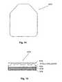
- FIG. 14is a top plan view of an improved personnel armour system
- the present inventionprovides improved ceramic components for use in ceramic armour systems embodying ceramic components for deflecting and defeating projectiles imposing various levels of threats.
- the present inventionalso provides a shock-absorbing layer for reducing shock and trauma and for providing support to the armour.
- the present inventionalso provides enhanced stealth features. A number of terms used herein are defined below.
- Deflecting meanschanging of direction of an incoming projectile upon impact.
- Ceramic component system and integral ceramics platehave been used synonymously in this disclosure.
- FIG. 1shows the cross-section of one embodiment of personnel protection ceramic armour system 110 of the present invention.
- the ceramic armour systemcomprises a ceramic component 1110 , 1210 , or 1310 (to be described later).
- the ceramic componentis an integral ceramic plate, or a plurality of interconnected ceramic components providing an integral plate (as will be further described with respect to FIG. 11 ).
- the ceramic plate 1110 , 1210 , or 1310may have a flat front surface, or may have a deflecting front surface having at least one node thereon, and has a rear surface.
- a front spall layer 112(to be described later) is bonded to the front surface of the ceramic component 1110 , 1210 , or 1310 .
- a shock-absorbing layer 114is bonded to the rear surface of ceramic component 1110 , 1210 , or 1310 .
- the shock-absorbing layer 114may be formed of polymer-fibre composites including aramid fibres, carbon fibres, glass fibres, ceramic fibres, polyethylene fibres, ZYALONTM, Nylon 66, or a combination thereof.
- the shock-absorbing layer 114may be obtained by layering one type of fibre over another fibre in a suitable orientation and bonding them together with an adhesive.
- a shock-absorbing layer of 2 to 8 layersmay be created by gluing, either with an epoxy glue or with a polyurethane glue, one layer of carbon fibre over a layer of aramid and repeating the process as often as necessary.
- the shock-absorbing layeris used in combination with a ceramic mosaic component system in a chest plate configuration for reducing shock and trauma, and providing support, together with the front spall and the backing.
- the ceramic mosaicis a known ceramic configuration that is economical because ceramic tiles are mass-produced by pressing.
- a shock-absorbing layer 214(to be described later) is bonded to the rear surface of ceramic plate 1110 , 1210 , or 1310 .
- the above-described sub-structure 215is disposed at a predetermined distance from the exposed face of the hull 218 of the vehicle with bolts 217 .
- the hull 218 of the vehiclemay include a liner 220 . This provides an air-gap 216 between the exposed face of the shock-absorbing layer 214 and the hull 218 .
- the air-gap 216 between the hull 218 of the vehicle and the shock-absorbing layer 214 of the armouris provided to reduce infrared signature of the vehicle.
- the air-gapis 4 to 6 mm.
- Scattering of the radar signalsis normally obtained by adding a commercially-available foam, e.g., FRAGLIGHTTM on top of the front spall layer of the armour system 210 .
- FRAGLIGHTTMa commercially-available foam
- the scattering of the radar signalscan be enhanced significantly.
- one layer of foam in conjunction with noded ceramic armour systems of the present inventionwas used to scatter as much as 80% of the incoming signal.
- the layer of foamis 4 mm thick.
- the MAP ceramic component system(to be described later) can be used in the ceramic armour system of this invention that is distinct and superior to the presently-used MEXAS and LIBA systems, to protect vehicles, crafts and buildings.
- the ceramic material, shape, size, and thickness of the ceramic armour systemis determined by the overall design of the ballistic system, the level of threat, and economics. The remaining features, as specified above, may be added to create ceramic armour systems for vehicles, crafts and buildings.
- the front spall layer 212 of the armouris provided with a camouflage to minimize an attack.
- FIG. 3 and FIG. 4show a ceramic component 310 having a square ceramic base 312 with a plurality of spherical nodes 314 of one size disposed thereon. While FIG. 3 shows the shape of the ceramic base 312 to be square, it can alternatively be rectangular, triangular, pentagonal, hexagonal, etc.
- the ceramic component 310is shown to be planar herein, but it can alternatively be curved.
- the ceramic component 310may have overlapping complementary “L”-shaped edges or 45° beveled edges or 90° parallel edges for abutting the ceramic components to form a ceramic component system to be described hereafter in FIG. 11 .
- the size and shape of the ceramic component 310may also be varied depending upon the size of the object to be protected.
- FIG. 7 and FIG. 8show a ceramic component 710 having a square ceramic, base 712 with spherical nodes 714 of one size thereon provided with longitudinal channels 716 therethrough. Not all nodes and the ceramic base underneath nodes may be provided with the channels.
- the provision of the longitudinal channels 716reduces the weight of the ceramic component by up to 15% while maintaining, the improved deflecting and defeating capabilities.
- FIG. 7shows the shape of the ceramic base 712 to be square, it can alternatively be rectangular, triangular, pentagonal, hexagonal, etc.
- the ceramic component 712is shown to be planar, but it can alternatively be curved.
- FIG. 9 and FIG. 10show a ceramic component 910 having a square ceramic base 912 with spherical nodes of two different sizes 914 , 916 thereon which are each provided with a longitudinal channel 918 therethrough. Not all nodes and the ceramic base underneath the nodes may be provided with the channels. While FIG. 9 shows the shape of the ceramic base 710 to be square, it can alternatively be rectangular, triangular, pentagonal, hexagonal, etc.
- the ceramic component 910is shown to be planar, but it can alternatively be curved.
- the ceramic component 910may have overlapping complementary “L”-shaped edges or 45° bevelled edges or 90° parallel edges for abutting the ceramic components to form a ceramic component system to be described hereafter in FIG. 11 .
- the size and shape of the ceramic component 910may also be varied depending upon the size of the object to be protected.
- FIG. 11shows a cross-section of three embodiments of a ceramic component system 1110 formed by abutting a plurality of ceramic components which are described above in FIG. 3 to FIG. 10 and more especially the ceramic components shown in FIG. 9 .
- a systemis designated as Monolithic Advance Protection (MAP).
- the ceramic componentis provided with, for example, “L”-shaped edges 1114 , 1116 on each side of the component. Two adjacent ceramic components may be joined by aligning the “L”-shaped edges 1114 , 1116 and by filling the gap with an adhesive, preferably polyurethane and/or polyurethane thermoplastic.
- FIG. 12shows a portion of the top plan view of another ceramic component system that may be formed by embedding a plurality of ceramic components described above in FIG. 2 to FIG. 10 in a polymer adhesive matrix.
- a systemis designated as CELLULAR ADVANCE PROTECTION (CAP).
- the CAP system 1210comprises a plurality of ceramic components, each having a hexagonal ceramic base 1212 with one spherical node 1214 provided with a channel 1216 therethrough, that are joined together in a flat layer by an adhesive 1218 , preferably polyurethane.
- an adhesive 1218preferably polyurethane.
- smaller hexagonal ceramic components with one or few nodesare used.
- the layer of hexagonal ceramic componentsmakes use of the space efficiently and creates a flexible ceramic system suitable for incorporation in armours for objects with contours, e.g., body parts.
- the second support layer 1312is bonded to the first support layer 1311 and to the rear spall layer.
- the first and second support layers 1311 , 1312are formed of different ceramic compounds devoid of nodes which are prepared from the ceramic material CERAMORTM or ALCERAM-TTM.
- the CERAMORTMis used for providing a mechanical function
- ALCERAM-TTMis used for providing a thermo-mechanical function.
- the two support layers 1311 , 1312may be provided with an inter-layer 1314 of a polymer-ceramic fibre therebetween.
- the two layers 1311 , 1312 and the inter-layer 1314are bonded by an adhesive, preferably polyurethane.
- the two support layers 1311 , 1312may be duplicated as many times as desired depending upon the level of protection required.
- FIG. 14 and FIG. 15show an embodiment of an improved personnel ceramic armour system 1410 .
- This systemcomprises, in front to back order, at least one layer each of a front spall layer 1412 , the ceramic component system, including MAP 1110 , CAP 1210 , or LAP 1310 , a rear spall layer 1414 , and a backing 1416 . These layers are bonded together, preferably with an adhesive.
- front spall layer 1412 and rear spall layer 1414are comprised of a thin film, preferably polycarbonate but other plastic is also contemplated.
- An appropriate range for the polycarbonateis preferably between 0.007 inches and 0.030 inches. This thickness allows for the film to conform to the front surface of ceramic component system 1110 , 1210 , or 1310 . Specifically, if ceramic component system 1110 , 1210 , or 1310 includes nodes, the polymer film with a thickness between 0.007 inches and 0.030 inches is still able to conform to the shape of the nodes and follow the contours of the ceramic component system.
- front spall layer 1412 and rear spall layer 1414are primarily to confine the ceramic and mitigate any spall. As would be appreciated by those skilled in the art, the thickness of the polycarbonate film is too thin to actually disturb the projectile and break any jacket of the projectile.
- the front spall layer 1412 and rear spall layer 1414are preferably bonded to the ceramic component system 1110 , 1210 or 1310 by a polyurethane film adhesive with a thickness of between 0.015 inches to 0.025 inches.
- the backing 1416is at least one layer of poly-paraphenylene terephthalamide fibres, polyethylene, glass fibres, or a metal, wherein the metal may be steel, aluminum, or any other suitable metal.
- the poly-paraphenylene terephthalamide fibres polyethylene fibresare known by trade names of KEVLARTM and SPECTRATM, respectively.
- An inter-layer 1418may be disposed in-between the rear spall layer 1414 and the backing 1416 in order to reduce back face deformation.
- the inter-layer 1418may be formed of a polymer-ceramic fibre composite.
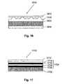
- FIG. 16shows one embodiment of an improved personnel ceramic armour system 1610 which includes, in front to back order, one layer of a polycarbonate front spall layer 1612 , one layer of the ceramic component system MAP 1110 (as described hereabove), a shock-absorbing composite layer 1614 made of 2 to 8 layers of glass fibres or aramid fibres, carbon fibres, and polycarbonate, glass fibres, or carbon fibres, wherein each layer is disposed at a suitable angle, e.g., 90° to the previous layer, and a degraded backing 1616 .
- These layersare bonded together, preferably, with a polymer adhesive.
- the polymer adhesiveis a thermoplastic, preferably a polyurethane adhesive and/or a polyurethane thermoplastic film.
- the front spall, the shock-absorbing composite layer, and the degraded backingmay be adhesive-impregnated, and thus may be used to manufacture the armour system.
- FIG. 17shows a side view of an embodiment of an armour system 1710 utilizing a LAP system 1724 comprising in front to back order, a front spall layer 1712 , a first layer of CERAMORTM V 1714 , a first layer of CERAMORTM L 1716 , a second layer of CERAMORTM V 1718 , a second layer of CERAMORTM L 1720 , and a shock-absorbing layer 1722 .
- the complete assemblycan then be bolted onto a vehicle for protection, preferably with an air-gap or alternatively without an air-gap.
- Such armour systemsshowed improved ballistic performance in tests done by Department of National Defense in Canada.
- CERAMORTM ceramic composite used in the present inventionis a tough ceramic composite material that provides close multi-hit capability.
- the personnel donning the armourare often subjected to multiple hits over time. Thus, from time to time it is essential to determine if the future protective capabilities of an armour have been compromised by past attacks. That is, it would be essential to determine stress level of a personnel armour system.
- the “stress level” hereinmeans cracks appearing in the ceramic plate due to the number of hits taken by the armour. Normally, stress level of an armour system is determined by X-ray technique, which method is quite expensive.
- the rear spall layer and the backingmay be bonded to assembled layers at the same time or they may be assembled in a group first and then the group is bonded to the assembled layers. Different layers may be bonded together in one group or in different groups. The different groups may then be bonded together to form one group. Epoxy resins may be used as an adhesive.
- the improved deflecting and defeating capability of the ceramic components, ceramic component systems, and ceramic armour systems described hereinwas confirmed by conducting depth penetration tests.
- An armouris considered improved if it showed reduced depth of penetration or no penetration in comparison with penetration which was allowed by the prior art.
- the personnel ceramic armour systemwas subjected to depth penetration tests. In comparison to the prior art, ceramic components devoid of nodes, the personnel ceramic armour system shows reduced depth of penetration or no penetration.
- a ceramic component devoid of nodescan only protect an object from the threat of a level IV armour-piercing projectile having a diameter of 7.62 mm.
- the use of single layer of a MAP ceramic component systemcan deflect and defeat a threat posed by a level V armour-piercing projectile having a diameter of 12.5 mm.
- a Rocket Propelled Grenadeusually poses such a threat.
- the active armoursgenerally include explosives that are provided on vulnerable areas of the object to be protected to counter-attack the approaching RPG.
- the active armoursthough effective, can accidentally explode onto the surface of the object to be protected, thereby endangering the object and/or the life of the personnel inside the object.
- the RPGejects molten Cu (Cu plasma jet) at a very high temperature and pressure onto the surface of the object after the impact.
- the Cu plasma jetpierces through the walls of the object and provides an avenue for entry of bomblets into the object. Once inside the object, the bomblets explode, destroying the object and the personnel inside the object.
- the Cu plasma jetcan pierce through 0.8 to 1.0 m of steel or 5 feet of concrete.
- a multi-layer ceramic component system disclosed hereinhas been shown to deflect and defeat the high level of threat posed by the Cu plasma jet of the RPG.
- one such systemprovides two supporting layers underneath the MAP.
- the two supporting layersmade from two types of ceramic material, each having different high-melting-temperature-resisting properties and pressure-resisting properties.
- These support layersprotect the object from the Cu plasma jet of the RPG in a stepwise manner.
- first support layerwhich is made of CERAMORTM which has a melting temperature of 2500° C. provides the first level of resistance to the high temperature and pressure of the Cu plasma jet of the RPG.
- the first layerabsorbs most of the temperature and a part of the pressure of the Cu plasma jet of the RPG, but the first support layer eventually cracks.
- the second support layerwhich is made of ALCERAM-TTM which has a melting temperature of 3000° C. provides the second level of resistance to the high temperature and pressure of the Cu plasma jet of the RPG.
- the second layerabsorbs the remaining temperature and pressure of the Cu plasma jet of the RPG, and does not melt or crack. Even if the second layer melts or cracks, when the heat will have dissipated, the second support layer will solidify again to provide protection.
- the present inventionprotects against the high temperature and pressure generated by the Cu plasma jet of the RPG.
- the two support layersmay also dissipate the temperature radially.
- the two support layersmay be provided with an inter-layer of polymer-ceramic fibres therebetween to provide more resistance to the temperature effect of the Cu plasma jet of the RPG.
- the ceramic armour systems of the present inventionpassed the most stringent international testing. All CERAMORTM systems were extensively tested for National Institute of Justice level III and IV threats. The testing of armour samples was conducted by H P White Laboratory (3114, Scarboro Road Street, Maryland 21154-1822, USA). A variety of ammunition was used during testing.
- test samples for the personnel protection armour systemwere mounted on an indoor range 50 feet from the muzzle of a test barrel to produce zero degree obliquity impacts.
- Photoelectric lumiline screenswere positioned at 6.5 and 9.5 feet which, in conjunction with elapsed time counter (chronographs), were used to compute projectile velocities 8.0 feet forward of the muzzle.
- Penetrationswere determined by visual examination of a witness panel of 0.020 inch thickness of 2024T3 aluminum positioned 6.0 inches behind and parallel to the test samples.
- CERAMORTM MAP strike plateof 2.6 kg could stop two 7.62 mm AP M2 projectiles at a velocity of 875 m/s or two 7.62 AP Swiss projectiles with tungsten carbide core at 825 m/s.
- a CERAMORTM MAP Strike plate armour system having 3.5 lbs/sq.ft. of ceramic weight and total weight of 5.65 lbs/sq.ft. with SPECTRATM backingwas tested for level III+ test which has a requirement of stopping two bullets out of four bullets.
- the CERAMORTM MAP strike plate test armourstopped the all four bullets.
- test samples for the vehicle protection armour systemwere mounted on an indoor range of 45 feet from the muzzle of a test barrel to produce zero degree obliquity impacts.
- Photoelectric lumiline screenswere positioned at 15.0 and 35.0 feet which, in conjunction with elapsed time counter (chronographs), were used to compute projectile velocities 25 feet forward of the muzzle.
- Penetrationswere determined by visual examination of a witness panel of 0.020 inch thickness of 2024T3 aluminum positioned 6.0 inches behind and parallel to the test samples.
- test armour plate of the present inventionhaving a size of 12′′ ⁇ 12′′ was hit by 5 projectiles (14.5 mm AP B32) at 900 m/s at less than 2′′ apart. No penetration was observed.
- the effectiveness of a ceramic component, and of an armour using such ceramic components, in protecting an object from the impact of projectileis improved by providing nodes on the front surface of the ceramic base.
- the provision of nodesadds the deflecting capability to the ceramic component and to the armour using ceramic components.
- the nodeschange the angle of the impacted projectile and retard the passage of the projectile through the ceramic component.
- the projectileis then easily defeated.
- the presence of nodes on the ceramic component disclosed in the present inventionis more effective in protecting an object than a ceramic component devoid of nodes, thereby eliminating the need for using thicker ceramic components for protecting an object from the same level of threat.
- the reduced thicknessleads to a lighter ceramic component, ceramic component system, and ceramic armour system.
- the provision of channelsalso adds to the lightness of ceramic components and ceramic armour systems.
- the stealth features, e.g., air-gap, foam layer, and camouflage surfaceminimizes the attack.
- the ceramic armour systems of the present inventionprovide improved ballistic performance and survivability, multi-hit capability, reduced damaged area, low areal density, flexible design, reduced back face deformation, shock, and trauma, and many stealth features over prior art systems.
- the ceramic armour system for vehicles, crafts, and buildingsin addition also protect the surfaces of these structures from damage by fragments. For example, in the case of a vehicle, it protects the hull.
- the ceramic armour systems for vehicles, for example, tankscan also be used as an add-on armour without the requirement of an internal liner.
- the armour system described hereinfunctions to protect an object by deflecting and defeating a projectile.
- the ceramic armour systemprovides better protection from projectile threats to ground vehicles, aircrafts, watercrafts, spacecrafts, buildings, shelters, and personnel, including body, helmet and shields.
Landscapes
- Engineering & Computer Science (AREA)
- Chemical & Material Sciences (AREA)
- Ceramic Engineering (AREA)
- General Engineering & Computer Science (AREA)
- Aiming, Guidance, Guns With A Light Source, Armor, Camouflage, And Targets (AREA)
- Laminated Bodies (AREA)
Abstract
Description
Claims (12)
Priority Applications (1)
| Application Number | Priority Date | Filing Date | Title |
|---|---|---|---|
| US12/649,431US8215223B2 (en) | 2001-07-25 | 2009-12-30 | Ceramic components, ceramic component systems, and ceramic armour systems |
Applications Claiming Priority (6)
| Application Number | Priority Date | Filing Date | Title |
|---|---|---|---|
| US30737801P | 2001-07-25 | 2001-07-25 | |
| PCT/CA2002/001134WO2003010484A1 (en) | 2001-07-25 | 2002-07-24 | Ceramic armour systems with a front spall layer and a shock absorbing layer |
| US10/332,897US6912944B2 (en) | 2001-07-25 | 2002-07-24 | Ceramic armour systems with a front spall layer and a shock absorbing layer |
| US11/068,663US7562612B2 (en) | 2001-07-25 | 2005-02-28 | Ceramic components, ceramic component systems, and ceramic armour systems |
| US11/978,889US20080264243A1 (en) | 2001-07-25 | 2007-10-30 | Ceramic components, ceramic component systems, and ceramic armour systems |
| US12/649,431US8215223B2 (en) | 2001-07-25 | 2009-12-30 | Ceramic components, ceramic component systems, and ceramic armour systems |
Related Parent Applications (1)
| Application Number | Title | Priority Date | Filing Date |
|---|---|---|---|
| US11/978,889DivisionUS20080264243A1 (en) | 2001-07-25 | 2007-10-30 | Ceramic components, ceramic component systems, and ceramic armour systems |
Publications (2)
| Publication Number | Publication Date |
|---|---|
| US20100154623A1 US20100154623A1 (en) | 2010-06-24 |
| US8215223B2true US8215223B2 (en) | 2012-07-10 |
Family
ID=46150456
Family Applications (4)
| Application Number | Title | Priority Date | Filing Date |
|---|---|---|---|
| US11/068,663Expired - LifetimeUS7562612B2 (en) | 2001-07-25 | 2005-02-28 | Ceramic components, ceramic component systems, and ceramic armour systems |
| US11/978,889AbandonedUS20080264243A1 (en) | 2001-07-25 | 2007-10-30 | Ceramic components, ceramic component systems, and ceramic armour systems |
| US12/649,431Expired - Fee RelatedUS8215223B2 (en) | 2001-07-25 | 2009-12-30 | Ceramic components, ceramic component systems, and ceramic armour systems |
| US12/649,446AbandonedUS20100101403A1 (en) | 2001-07-25 | 2009-12-30 | Ceramic components, ceramic component systems, and ceramic armour systems |
Family Applications Before (2)
| Application Number | Title | Priority Date | Filing Date |
|---|---|---|---|
| US11/068,663Expired - LifetimeUS7562612B2 (en) | 2001-07-25 | 2005-02-28 | Ceramic components, ceramic component systems, and ceramic armour systems |
| US11/978,889AbandonedUS20080264243A1 (en) | 2001-07-25 | 2007-10-30 | Ceramic components, ceramic component systems, and ceramic armour systems |
Family Applications After (1)
| Application Number | Title | Priority Date | Filing Date |
|---|---|---|---|
| US12/649,446AbandonedUS20100101403A1 (en) | 2001-07-25 | 2009-12-30 | Ceramic components, ceramic component systems, and ceramic armour systems |
Country Status (1)
| Country | Link |
|---|---|
| US (4) | US7562612B2 (en) |
Cited By (12)
| Publication number | Priority date | Publication date | Assignee | Title |
|---|---|---|---|---|
| US20130061635A1 (en)* | 2011-09-13 | 2013-03-14 | Asahi Glass Company, Limited | Method for measuring strength of chemically strengthened glass, method for reproducing cracking of chemically strengthened glass, and method for producing chemically strengthened glass |
| US8746122B1 (en) | 2010-04-12 | 2014-06-10 | The Government Of The United States Of America, As Represented By The Secretary Of The Navy | Multi-ply heterogeneous armor with viscoelastic layers and a corrugated front surface |
| US20140192474A1 (en)* | 2013-01-10 | 2014-07-10 | Dell Products L.P. | Composite chassis for lowering surface temperature |
| US9400524B2 (en) | 2012-11-07 | 2016-07-26 | Dell Products L.P. | Metal ceramic chassis for portable devices |
| US9410772B2 (en) | 2011-06-01 | 2016-08-09 | FCT Igenieurkermik GmbH | Ballistic protection configuration |
| US9452570B2 (en) | 2012-11-07 | 2016-09-27 | Dell Products L.P. | Information handling system ceramic chassis |
| WO2019038720A1 (en) | 2017-08-23 | 2019-02-28 | Agp America S.A. | Transparent multi-hit armor |
| US10751983B1 (en) | 2016-11-23 | 2020-08-25 | The United States Of America, As Represented By The Secretary Of The Navy | Multilayer composite structure having geometrically defined ceramic inclusions |
| WO2021156883A1 (en)* | 2020-02-06 | 2021-08-12 | Ashish Kansal | Multi-impact monolithic ballistic armour plate |
| US11131527B1 (en)* | 2016-11-23 | 2021-09-28 | The United States Of America, As Represented By The Secretary Of The Navy | Composite material system including elastomeric, ceramic, and fabric layers |
| US11415395B1 (en) | 2021-07-14 | 2022-08-16 | Corner Edge Technologies | Ballistic shield and method of manufacture |
| US20230366658A1 (en)* | 2022-05-16 | 2023-11-16 | Timo Olavi Tervola | Compact ballistic shield with offset spaced components for improved performance |
Families Citing this family (41)
| Publication number | Priority date | Publication date | Assignee | Title |
|---|---|---|---|---|
| US7562612B2 (en)* | 2001-07-25 | 2009-07-21 | Aceram Materials & Technologies, Inc. | Ceramic components, ceramic component systems, and ceramic armour systems |
| US20120174754A1 (en)* | 2003-10-28 | 2012-07-12 | Strike Face Technology Incorporated | Ceramic armour and method of construction |
| US7251835B2 (en)* | 2003-11-14 | 2007-08-07 | Ultra Shield, Inc. | Soft armor |
| US9441918B1 (en) | 2004-12-08 | 2016-09-13 | Armor Dynamics, Inc. | Armor system |
| US8104396B2 (en)* | 2005-12-08 | 2012-01-31 | Armordynamics, Inc. | Reactive armor system and method |
| US8220378B2 (en)* | 2005-06-21 | 2012-07-17 | Specialty Products, Inc. | Composite armor panel and method of manufacturing same |
| ITFI20050210A1 (en)* | 2005-10-07 | 2007-04-08 | Cosimo Cioffi | CLOTHING STRUCTURE FOR SELF-PROTECTION |
| US7866248B2 (en) | 2006-01-23 | 2011-01-11 | Intellectual Property Holdings, Llc | Encapsulated ceramic composite armor |
| WO2008048218A2 (en)* | 2006-07-26 | 2008-04-24 | Specialty Products, Inc. | Composite armor panel and method of manufacturing same |
| US8689671B2 (en)* | 2006-09-29 | 2014-04-08 | Federal-Mogul World Wide, Inc. | Lightweight armor and methods of making |
| US8087339B2 (en)* | 2007-07-24 | 2012-01-03 | Foster-Miller, Inc. | Armor system |
| US20100212484A1 (en)* | 2007-09-26 | 2010-08-26 | Williams Raymond F | Method and apparatus for changing the trajectory of a projectile |
| US9347746B1 (en)* | 2008-01-03 | 2016-05-24 | Great Lakes Armor Systems, Inc. | Armored energy-dispersion objects and method of making and using |
| US8096223B1 (en)* | 2008-01-03 | 2012-01-17 | Andrews Mark D | Multi-layer composite armor and method |
| US8176831B2 (en)* | 2009-04-10 | 2012-05-15 | Nova Research, Inc. | Armor plate |
| US8646373B1 (en)* | 2009-05-04 | 2014-02-11 | Nova Research, Inc. | Blast wave effects reduction system |
| DE102009053349B4 (en)* | 2009-11-17 | 2014-07-03 | Benteler Defense Gmbh & Co. Kg | Armored steel component |
| US20110203452A1 (en)* | 2010-02-19 | 2011-08-25 | Nova Research, Inc. | Armor plate |
| US9207048B1 (en)* | 2010-04-12 | 2015-12-08 | The United States Of America, As Represented By The Secretary Of The Navy | Multi-ply heterogeneous armor with viscoelastic layers and hemispherical, conical, and angled laminate strikeface projections |
| US8978535B2 (en)* | 2010-08-11 | 2015-03-17 | Massachusetts Institute Of Technology | Articulating protective system for resisting mechanical loads |
| US8695476B2 (en) | 2011-03-14 | 2014-04-15 | The United States Of America, As Represented By The Secretary Of The Navy | Armor plate with shock wave absorbing properties |
| US9040160B2 (en) | 2011-04-08 | 2015-05-26 | Schott Corporation | Multilayer armor |
| WO2012170874A1 (en)* | 2011-06-08 | 2012-12-13 | American Technical Coatings, Inc. | Enhanced ballistic protective system |
| IL213865A (en) | 2011-06-30 | 2017-02-28 | Bergman Ron | Antiballistic article and method of producing same |
| US9696122B2 (en) | 2011-06-30 | 2017-07-04 | Imi Systems Ltd. | Antiballistic article and method of producing same |
| CN103486907A (en)* | 2013-09-10 | 2014-01-01 | 上海斯瑞科技有限公司 | Surface structure capable of improving bulletproof performance of integral ceramic plate and method for processing surface structure |
| IL230775B (en) | 2014-02-02 | 2018-12-31 | Imi Systems Ltd | Pre-stressed curved ceramic plates/tiles and method of producing same |
| CN103868413A (en)* | 2014-02-24 | 2014-06-18 | 北京同益中特种纤维技术开发有限公司 | Ceramic composite bulletproof plate |
| CA2943081C (en) | 2014-03-18 | 2020-07-21 | American Technical Coatings, Inc. | Lightweight enhanced ballistic armor system |
| US20160145865A1 (en)* | 2014-11-26 | 2016-05-26 | Foster-Miller, Inc. | Protective panel |
| US10775137B2 (en)* | 2017-05-16 | 2020-09-15 | A. Jacob Ganor | Up-armor kit for ballistic helmet |
| DE102017116319A1 (en)* | 2017-07-19 | 2019-01-24 | Kennametal Inc. | Armor plate and armor consisting of carrier and armor plate |
| DE102019116153A1 (en) | 2019-06-13 | 2020-12-17 | Kennametal Inc. | Armor plate, armor plate composite and armor |
| CN111366038B (en)* | 2020-03-20 | 2022-03-25 | 吉林大学 | A bionic bulletproof insert that can change the direction of the warhead |
| FR3112201B3 (en)* | 2020-07-02 | 2022-07-01 | Saint Gobain Ct Recherches | PROFILE SHIELDING ELEMENT |
| EP4306899A4 (en)* | 2021-03-12 | 2024-12-11 | Michel Baikrich | Retractable mechanism with shock-absorbing effect, which increases the ballistic resistance of a spall liner fixed inside an armoured vehicle |
| DE102022100599A1 (en) | 2022-01-12 | 2023-08-03 | Kennametal Inc. | Armor Plate, Armor Plate Composite, and Armor |
| CN114894037A (en)* | 2022-05-23 | 2022-08-12 | 中国人民解放军海军工程大学 | Deflection yawing type composite protection structure |
| CN115402465A (en)* | 2022-08-18 | 2022-11-29 | 中国人民解放军海军工程大学 | Deflection and yaw ballistic protection liquid tank structure |
| CN116255870B (en)* | 2023-02-22 | 2025-02-18 | 哈尔滨工程大学 | Preparation method of ceramic composite armor with bionic structure |
| CN117073463A (en)* | 2023-09-07 | 2023-11-17 | 中航装甲科技有限公司 | A kind of composite armor with bionic structure and preparation method thereof |
Citations (126)
| Publication number | Priority date | Publication date | Assignee | Title |
|---|---|---|---|---|
| DE27436C (en) | J. W. SPENCER in Newburn-Steel-Works b. Ne\vcastle on Tyne und W. BAGSHAWE in Newcas(!e on Tyne | Innovations to armor plates | ||
| FR335605A (en) | 1903-09-29 | 1904-02-03 | Cleland Davis | Deflection armor plate |
| FR1041126A (en) | 1951-08-07 | 1953-10-21 | Protective armor against shaped charge projectiles | |
| US3179553A (en) | 1963-03-12 | 1965-04-20 | Philip J Franklin | Lightweight armor plate |
| US3395067A (en) | 1964-10-12 | 1968-07-30 | Aerojet General Co | Composite laminated armor plate with internal projectile-deflecting surfaces |
| US3431818A (en) | 1965-04-26 | 1969-03-11 | Aerojet General Co | Lightweight protective armor plate |
| US3523057A (en) | 1965-10-24 | 1970-08-04 | Schjeldahl Co G T | Ball and plastic armour plate |
| US3616115A (en) | 1968-09-24 | 1971-10-26 | North American Rockwell | Lightweight ballistic armor |
| US3634177A (en) | 1966-11-01 | 1972-01-11 | Gen Electric | Lightweight transparent penetration-resistant structure |
| US3649426A (en) | 1967-12-22 | 1972-03-14 | Hughes Aircraft Co | Flexible protective armour material and method of making same |
| US3705558A (en) | 1963-04-24 | 1972-12-12 | Gen Motors Corp | Armor |
| US3813281A (en) | 1973-01-30 | 1974-05-28 | Gulf & Western Ind Prod Co | Composite flexible armor |
| US3832266A (en) | 1972-12-05 | 1974-08-27 | Us Army | Fiberglass laminate backed ceramic armor |
| US3977294A (en)* | 1971-09-07 | 1976-08-31 | Fiber Materials, Inc. | Composite armor and method |
| DE2853154A1 (en) | 1978-12-08 | 1980-08-14 | Harry Apprich | Armour plating for vehicle walls or bulletproof vests - using metal plates with stamped profiled holes to absorb energy in bullets etc. |
| DE2927653A1 (en) | 1979-07-09 | 1981-01-29 | Hopp Ing Buero | Bulletproof material - comprising hot pressed laminate of alternating layers of extensible fibre fabric and thermoplastic film |
| FR2519133A1 (en) | 1981-12-29 | 1983-07-01 | Graner Joseph | Penetration resistant armour plate - has front plate with shaped and spaced cones to deflect projectiles |
| US4483020A (en) | 1982-11-17 | 1984-11-20 | Jack P. Cittadine | Projectile proof vest |
| GB2156272A (en) | 1984-03-17 | 1985-10-09 | Michael Sacks | Protective shields |
| DE3228264A1 (en) | 1981-08-13 | 1985-12-05 | Harry 7311 Hochdorf Apprich | Bulletproof multi-layer material |
| EP0168746A1 (en) | 1984-07-18 | 1986-01-22 | Val. Mehler AG | Armour plate |
| EP0237095A1 (en) | 1986-02-22 | 1987-09-16 | Akzo N.V. | Armour plate composite with ceramic impact layer |
| US4739690A (en) | 1984-04-10 | 1988-04-26 | Ceradyne, Inc. | Ballistic armor with spall shield containing an outer layer of plasticized resin |
| US4757742A (en) | 1982-09-27 | 1988-07-19 | Ara, Inc. | Composite ballistic armor system |
| US4812359A (en) | 1984-04-04 | 1989-03-14 | Pilkington Brothers P.L.C. | Impact-resistant laminate |
| US4861666A (en) | 1984-08-13 | 1989-08-29 | General Electric Company | Asymmetric impact resistant laminates |
| US4908083A (en) | 1984-04-04 | 1990-03-13 | Pilkington Plc | Impact-resistant laminate |
| US4934245A (en) | 1987-09-18 | 1990-06-19 | Fmc Corporation | Active spall suppression armor |
| US4953442A (en)* | 1986-01-07 | 1990-09-04 | Harsco Corporation | Magnetized ceramic armor system |
| DE3907375A1 (en) | 1989-03-08 | 1990-09-13 | Blohm Voss Ag | Multilayer plate for armouring the walls of vehicles, in particular ships |
| WO1991006823A2 (en) | 1989-11-03 | 1991-05-16 | Allied-Signal Inc. | Ceramic armor reinforced with high-strength fibers and ballistic resistant articles formed from said armor |
| WO1991007632A1 (en) | 1989-11-13 | 1991-05-30 | Allied-Signal Inc. | Ballistic resistant composite armor |
| US5032466A (en) | 1987-10-16 | 1991-07-16 | Lasar S.P.A. | Semi-rigid stratified shield |
| DE4125918A1 (en) | 1990-08-07 | 1992-02-13 | Ficht Gmbh | Composite bulletproof sheet - has metal or plastic skins and core of hard ceramic layers with matching prismatic type relief faces bonded together to absorb shock waves |
| US5114772A (en)* | 1988-12-19 | 1992-05-19 | Societe Europeenne De Propulsion | Protective material having a multilayer ceramic structure |
| DE4114809A1 (en) | 1991-05-07 | 1992-11-12 | Gerd Dr Ing Kellner | Lightweight bullet-proof plate material - comprising ceramic or metallic front layer joined by elastic bonding agent to multilayer elasticated laminate |
| GB2260600A (en) | 1991-10-16 | 1993-04-21 | Wahl Verschleiss Tech | Armour plate |
| EP0334263B1 (en) | 1988-03-23 | 1994-05-04 | Fmc Corporation | Improved active spall suppression armor |
| US5318847A (en) | 1991-10-11 | 1994-06-07 | Yamaha Corporation | Carbodiimide treated carbon fiber and use thereof |
| US5326606A (en) | 1992-08-12 | 1994-07-05 | Armorvision Plastics & Glass | Bullet proof panel |
| US5340633A (en) | 1990-11-28 | 1994-08-23 | Dsm, N.V. | Multilayer antiballistic structure |
| GB2276934A (en) | 1993-04-07 | 1994-10-12 | Courtaulds Aerospace Ltd | Composite ballistic armour |
| GB2276933A (en) | 1993-04-07 | 1994-10-12 | Courtaulds Aerospace Ltd | Composite ballistic armour |
| GB2276935A (en) | 1993-04-07 | 1994-10-12 | Courtaulds Aerospace Ltd | Composite ballistic armour |
| EP0620411A1 (en) | 1993-04-07 | 1994-10-19 | Courtaulds Aerospace Limited | Ballistic armour composites |
| GB2277141A (en) | 1993-04-07 | 1994-10-19 | Courtaulds Aerospace Ltd | Composite ballistic armour |
| DD301990A9 (en) | 1986-03-25 | 1994-10-20 | Vormals Ministerium Des Innern | Splinter guard |
| US5364679A (en) | 1985-07-02 | 1994-11-15 | Dorothy Groves | Flexible armour with energy absorbing half-spheres or hemispherically-shaped bodies |
| WO1995010751A1 (en) | 1993-10-13 | 1995-04-20 | Rossiisky Federalny Yaderny Tsentr - Vserossiisky Nauchno-Issledovatelsky Institut Experimentalnoi Fiziki | Armoured element and method of manufacturing the same |
| GB2283902A (en) | 1993-11-10 | 1995-05-24 | T & N Technology Ltd | Armour, e.g. for jackets |
| GB2285209A (en) | 1994-01-04 | 1995-07-05 | Lionel Bryant | Flexible protective cladding |
| GB2287639A (en) | 1994-03-21 | 1995-09-27 | Lionel Bryant | Flexible protective cladding |
| US5469773A (en) | 1965-09-23 | 1995-11-28 | The United States Of America As Represented By The Secretary Of The Army | Light weight armor |
| USH1519H (en) | 1966-01-24 | 1996-03-05 | The United States Of America As Represented By The Secretary Of The Army | Transparent ceramic composite armor |
| US5534343A (en) | 1994-07-15 | 1996-07-09 | Supracor Systems, Inc. | Flexible ballistic resistant article having a thermoplastic elastomeric honeycomb panel |
| US5554816A (en) | 1994-05-13 | 1996-09-10 | Skaggs; Samuel R. | Reactive ballistic protection devices |
| DE19509899A1 (en) | 1995-03-18 | 1996-09-19 | Gerd Dr Ing Kellner | Multi-layer armor protection material |
| US5560971A (en) | 1995-04-18 | 1996-10-01 | Milliken Research Corporation | Multi-layer material for suppression of ceramic shrapnel created during a ballistic event |
| US5635288A (en) | 1994-05-17 | 1997-06-03 | Park; Andrew D. | Ballistic resistant composite for hard-armor application |
| EP0810415A2 (en) | 1996-05-30 | 1997-12-03 | Fmc Corporation | Interlayer for ceramic armor |
| US5738925A (en) | 1996-04-10 | 1998-04-14 | Lockheed Martin Corporation | Ballistic armor having a flexible load distribution system |
| DE19643745A1 (en) | 1996-10-23 | 1998-04-30 | Etec Energieoptimierung | Bulletproof protection device for persons, vehicles, etc. |
| US5804757A (en) | 1996-03-29 | 1998-09-08 | Real World Consulting, Inc. | Flexible, lightweight, compound body armor |
| US5847308A (en) | 1996-05-30 | 1998-12-08 | United Defense, Lp | Passive roof armor |
| WO1999011997A1 (en) | 1997-09-04 | 1999-03-11 | Akzo Nobel Nv | Composite system for protection against bullets and fragments |
| WO1999022195A1 (en) | 1997-10-24 | 1999-05-06 | Lanxide Technology Company, Lp | Armor material and methods of making same |
| US5905225A (en) | 1995-10-25 | 1999-05-18 | Denel (Proprietary) Ltd. | Armouring |
| EP0942255A1 (en) | 1998-03-10 | 1999-09-15 | Mofet Etzion | Composite armor panel |
| GB2335388A (en) | 1998-03-21 | 1999-09-22 | Lightweight Body Armour Limite | Composite material particularly for use as anti-stab armour |
| GB2336807A (en) | 1998-04-27 | 1999-11-03 | David Adie | Ceramic sandwich material for ballistic protection |
| US5996115A (en) | 1992-08-24 | 1999-12-07 | Ara, Inc. | Flexible body armor |
| US6009789A (en) | 1997-05-01 | 2000-01-04 | Simula Inc. | Ceramic tile armor with enhanced joint and edge protection |
| WO2000033015A2 (en) | 1998-12-02 | 2000-06-08 | Atlantic Research Corporation | Shock attenuation barrier |
| US6112635A (en) | 1996-08-26 | 2000-09-05 | Mofet Etzion | Composite armor panel |
| US6135006A (en) | 1997-05-12 | 2000-10-24 | Northrop Grumman Corporation | Fiber reinforced ceramic matrix composite armor |
| US6138275A (en) | 1993-08-04 | 2000-10-31 | Sacks; Michael | Layered armored shield |
| US6170378B1 (en) | 1998-11-09 | 2001-01-09 | Murray L. Neal | Method and apparatus for defeating high-velocity projectiles |
| US6203908B1 (en) | 1996-08-26 | 2001-03-20 | Michael Cohen | Composite armor |
| US6253655B1 (en) | 1999-02-18 | 2001-07-03 | Simula, Inc. | Lightweight armor with a durable spall cover |
| US6370690B1 (en) | 2001-03-19 | 2002-04-16 | Murray L. Neal | Lightweight fragmentation resistant body armor configuration |
| US6389594B1 (en) | 2001-08-30 | 2002-05-21 | Israel Military Industries Ltd. | Anti-ballistic ceramic articles |
| WO2002041719A1 (en) | 2000-11-27 | 2002-05-30 | Astron Elastomerprodukte Gesellschaft M.B.H. | Device for the protection of body parts from penetrating objects and protective suit using said protection device |
| US6408733B1 (en) | 2000-02-14 | 2002-06-25 | William J. Perciballi | Ceramic armor apparatus for multiple bullet protection |
| US6418832B1 (en) | 2000-04-26 | 2002-07-16 | Pyramid Technologies International, Inc. | Body armor |
| US20020178900A1 (en) | 2001-04-24 | 2002-12-05 | Ghiorse Seth R. | Armor with in-plane confinement of ceramic tiles |
| EP0807797B1 (en) | 1996-05-14 | 2002-12-18 | Röhm GmbH & Co. KG | Bullet resistant glass and use thereof |
| US6497966B2 (en) | 2001-01-15 | 2002-12-24 | Michael Cohen | Laminated armor |
| GB2377006A (en) | 2001-06-30 | 2002-12-31 | David Adie | Ballistic protection shield |
| EP0995730B1 (en) | 1998-10-14 | 2003-01-29 | ECM Ingenieur-Unternehmen für Energie-und Umwelttechnik GmbH | Method of making siliconized bodies |
| EP1288607A1 (en) | 2001-08-24 | 2003-03-05 | Israel Military Industries Ltd. | Anti-ballistic ceramic articles |
| US6537654B1 (en) | 1999-11-04 | 2003-03-25 | Sgl Technik Gmbh | Protection products and armored products made of fiber-reinforced composite material with ceramic matrix |
| US6568310B2 (en) | 2001-10-25 | 2003-05-27 | Timothy W. Morgan | Lightweight armored panels and doors |
| US6575075B2 (en) | 2000-10-05 | 2003-06-10 | Michael Cohen | Composite armor panel |
| US20030139108A1 (en) | 2001-12-14 | 2003-07-24 | Australian Defence Apparel Pty Ltd. | Hard armour panels or plates and production method therefor |
| US20030151152A1 (en) | 2002-02-08 | 2003-08-14 | Coorstek, Inc. | Body armor and methods for its production |
| US6622608B1 (en) | 2001-06-26 | 2003-09-23 | United Defense Lp | Variable standoff extendable armor |
| US20030180517A1 (en) | 2000-03-14 | 2003-09-25 | Gerhard Karall | Material consisting of several layers for protecting parts of the body |
| WO2003086748A1 (en) | 2002-04-05 | 2003-10-23 | Hiform As | Lightweight antiballistic panel and method for making such panel |
| EP1369149A1 (en) | 2002-06-06 | 2003-12-10 | Euroin di Paludetto Renato | Protection device |
| US6679157B2 (en) | 1999-09-30 | 2004-01-20 | Bechtel Bwxt Idaho Llc | Lightweight armor system and process for producing the same |
| EP0994084B1 (en) | 1998-10-14 | 2004-01-21 | Industrieanlagen-Betriebsgesellschaft M.B.H. | Protective armour |
| US20040020353A1 (en) | 2002-05-12 | 2004-02-05 | Moshe Ravid | Ballistic armor |
| US20040028868A1 (en) | 2000-10-26 | 2004-02-12 | James Brynley Jonathan | Ceramic tile armour |
| US6698331B1 (en) | 1999-03-10 | 2004-03-02 | Fraunhofer Usa, Inc. | Use of metal foams in armor systems |
| US6713008B1 (en) | 2000-06-23 | 2004-03-30 | Darrin Blake Teeter | Method for making composite structures |
| US6737158B1 (en) | 2002-10-30 | 2004-05-18 | Gore Enterprise Holdings, Inc. | Porous polymeric membrane toughened composites |
| US20040097360A1 (en) | 2002-09-13 | 2004-05-20 | Bodo Benitsch | Fiber-reinforced composite ceramic, fabrication method and lining material, armor, reflective surface and component having the composite ceramic |
| US6745661B1 (en) | 1999-04-30 | 2004-06-08 | Pinnacle Armor, Inc. | Method and apparatus for defeating ballistic projectiles |
| US20040118271A1 (en) | 2002-07-01 | 2004-06-24 | Puckett David L. | Lightweight ceramic armor with improved blunt trauma protection |
| US6792843B2 (en) | 2000-05-11 | 2004-09-21 | Teijin Twaron Gmbh | Armor-plating composite |
| US6805034B1 (en) | 2000-01-11 | 2004-10-19 | M Cubed Technologies, Inc. | Silicon carbide armor bodies, and methods for making same |
| WO2004109216A2 (en) | 2002-10-28 | 2004-12-16 | The Boeing Company | Ballistic-resistant multilayered armor including a stitched composite reinforcement layer and method of making the same |
| US20050005762A1 (en) | 2003-02-10 | 2005-01-13 | Lujan Dardo Bonaparte | Armored assembly |
| EP1521051A1 (en) | 2003-10-02 | 2005-04-06 | Michael Cohen | Ceramic bodies for armor panel |
| US20050072294A1 (en) | 2003-08-26 | 2005-04-07 | Michael Cohen | Composite armor plate |
| EP1522817A1 (en) | 2003-10-09 | 2005-04-13 | Michael Cohen | A composite armor plate and ceramic bodies for use therein |
| US20050087064A1 (en) | 2003-09-22 | 2005-04-28 | Michael Cohen | Modular armored vehicle system |
| WO2005045351A1 (en) | 2003-11-06 | 2005-05-19 | Rufus Paul Roodt | Ballistic shield |
| US6895851B1 (en) | 2003-06-16 | 2005-05-24 | Ceramics Process Systems | Multi-structure metal matrix composite armor and method of making the same |
| US6899009B2 (en) | 2001-06-26 | 2005-05-31 | The United States Of America As Represented By The Administrator Of The National Aeronautics And Space Administration | Flexible multi-shock shield |
| US20050188831A1 (en) | 2003-07-11 | 2005-09-01 | Us Global Nanospace, Inc. | Ballistic resistant turret and method of making same |
| US20050217471A1 (en) | 2003-11-25 | 2005-10-06 | Sgl Carbon Ag | Ceramic antiballistic layer, process for producing the layer and protective device having the layer |
| WO2005098343A1 (en) | 2004-04-05 | 2005-10-20 | George Tunis | Armor panel system |
| US6995103B2 (en) | 2000-11-21 | 2006-02-07 | M Cubed Technologies, Inc. | Toughness enhanced silicon-containing composite bodies, and methods for making same |
| EP1637507A2 (en) | 2004-09-13 | 2006-03-22 | Michael Cohen | Alumina ceramic products |
| US20060065111A1 (en) | 2002-04-17 | 2006-03-30 | Henry James J M | Armor system |
Family Cites Families (46)
| Publication number | Priority date | Publication date | Assignee | Title |
|---|---|---|---|---|
| US374150A (en) | 1887-11-29 | William gray | ||
| US1264380A (en) | 1918-02-09 | 1918-04-30 | George W Dowthard | Armor for ships. |
| US3509833A (en)* | 1963-03-28 | 1970-05-05 | Goodyear Aerospace Corp | Hard faced ceramic and plastic armor |
| US3700534A (en)* | 1963-03-28 | 1972-10-24 | Goodyear Aircraft Corp | Hard faced plastic armorplate |
| US3444033A (en)* | 1964-06-22 | 1969-05-13 | Aerojet General Co | Lightweight armor with laminated base member resistant to delamination |
| US3380406A (en)* | 1965-04-28 | 1968-04-30 | Whittaker Corp | Composite design for transparent armour |
| US3771418A (en)* | 1971-09-29 | 1973-11-13 | Us Army | Anti-spall lightweight armor |
| DE2606569A1 (en) | 1976-02-19 | 1977-08-25 | Degussa | PROCESS FOR THE PRODUCTION OF BULLET-RESISTANT COMPOSITE (GLASS) PANELS |
| US4594290A (en)* | 1982-12-06 | 1986-06-10 | Swedlow, Inc. | Impact resistant laminate |
| US4633528A (en) | 1984-07-30 | 1987-01-06 | Brandt Raymond W | Bullet affecting/deflecting material |
| US4674394A (en)* | 1985-10-16 | 1987-06-23 | Pro-Tech Armored Products Of New York, Inc. | Portable bullet-proof shield |
| US4861668A (en)* | 1986-12-24 | 1989-08-29 | Monsanto Company | Process for coating urethane substrates |
| DE3715917A1 (en)* | 1987-05-13 | 1988-12-01 | Niemsch Otto Lanico Maschbau | MACHINE FOR DOUBLE-SIDED BOARDING AND PULLING IN CYLINDRICAL CAN FELS |
| US4739890A (en)* | 1987-06-15 | 1988-04-26 | Cooke Carl W | Closure for container |
| US4876941A (en)* | 1987-12-31 | 1989-10-31 | Eltech Systems Corporation | Composite for protection against armor-piercing projectiles |
| US4879165A (en)* | 1988-06-20 | 1989-11-07 | Smith W Novis | Lightweight armor |
| US5368904A (en) | 1988-07-18 | 1994-11-29 | Stephinson; William P. | Bullet resistant glass |
| US5127045A (en) | 1989-11-16 | 1992-06-30 | Cragun David R | Identifying telephone controller system |
| WO1992009861A2 (en) | 1990-11-21 | 1992-06-11 | Allied-Signal Inc. | Ballistic resistant composite armor |
| US5515541A (en) | 1991-11-23 | 1996-05-14 | Michael Sacks | Flexible armor |
| DK0588212T3 (en) | 1992-09-17 | 1996-12-23 | Fmc Corp | Advanced burst coat system |
| BR9500783A (en) | 1994-02-28 | 1995-10-24 | Niltar Trading S A | Anti-trauma pack |
| GB9522101D0 (en) | 1995-10-28 | 1996-07-17 | Aigis Ltd | Blast attenuation |
| NL1005707C2 (en) | 1997-04-02 | 1998-10-05 | Fokker Special Products | Explosion protection device. |
| NL1005731C2 (en) | 1997-04-04 | 1998-10-07 | Zeffex Plastics Bv | Lightweight and flexible non-metallic stab resistant material. |
| US5915528A (en) | 1997-12-23 | 1999-06-29 | Shmuelov; Elyahu | Protective stripe assemblies with concave-convex interfaces |
| DE19802242C2 (en) | 1998-01-22 | 1999-11-11 | Akzo Nobel Nv | Stab and bullet protection clothing |
| JP2003526824A (en)* | 1998-02-27 | 2003-09-09 | エンゲイジ テクノロジーズ | User profile construction system and method |
| DE19825260B4 (en) | 1998-06-05 | 2007-02-08 | Geke Technologie Gmbh | Arrangement for protecting objects against shaped charges |
| EP0967453A1 (en) | 1998-06-25 | 1999-12-29 | Armortec Incorporated | Flexible, impact-resistant materials |
| KR100325302B1 (en)* | 1999-06-16 | 2002-02-21 | 김영환 | Method for Manufacturing of Semiconductor Device |
| US6200664B1 (en) | 1999-11-01 | 2001-03-13 | Ward Figge | Explosion barrier |
| US7018692B2 (en) | 2000-07-06 | 2006-03-28 | Higher Dimension Medical, Inc. | Penetration resistant fabric with multiple layer guard plate assemblies and method of making the same |
| US6962739B1 (en) | 2000-07-06 | 2005-11-08 | Higher Dimension Medical, Inc. | Supple penetration resistant fabric and method of making |
| US6575072B2 (en)* | 2000-11-09 | 2003-06-10 | Gilles Pellerin | Expansion joint within an anchor rode |
| US6862970B2 (en) | 2000-11-21 | 2005-03-08 | M Cubed Technologies, Inc. | Boron carbide composite bodies, and methods for making same |
| WO2002061365A1 (en) | 2000-12-13 | 2002-08-08 | Warwick Mills, Inc. | Wearable protective system having protective elements |
| US7562612B2 (en)* | 2001-07-25 | 2009-07-21 | Aceram Materials & Technologies, Inc. | Ceramic components, ceramic component systems, and ceramic armour systems |
| US6813360B2 (en)* | 2002-01-22 | 2004-11-02 | Avaya, Inc. | Audio conferencing with three-dimensional audio encoding |
| US6826996B2 (en) | 2002-03-11 | 2004-12-07 | General Dynamics Land Systems, Inc. | Structural composite armor and method of manufacturing it |
| JP2004050717A (en)* | 2002-07-23 | 2004-02-19 | Fanuc Ltd | Mold claming mechanism of injection molding machine |
| AU2003270085A1 (en) | 2002-09-03 | 2004-03-29 | University Of Virginia Patent Foundation | Blast and ballistic protection systems and method of making the same |
| US20040048536A1 (en) | 2002-09-05 | 2004-03-11 | Safeboard Ab | Stab resistant article |
| US7276458B2 (en) | 2003-01-27 | 2007-10-02 | Sheree H. Wen | Anti-ballistic fabric or other substrate |
| US7100490B2 (en) | 2003-07-01 | 2006-09-05 | Muller Jr Robert L | Body armor |
| US6997218B1 (en) | 2004-04-08 | 2006-02-14 | The United States Of America As Represented By The Secretary Of The Navy | Inflatable body armor system |
- 2005
- 2005-02-28USUS11/068,663patent/US7562612B2/ennot_activeExpired - Lifetime
- 2007
- 2007-10-30USUS11/978,889patent/US20080264243A1/ennot_activeAbandoned
- 2009
- 2009-12-30USUS12/649,431patent/US8215223B2/ennot_activeExpired - Fee Related
- 2009-12-30USUS12/649,446patent/US20100101403A1/ennot_activeAbandoned
Patent Citations (133)
| Publication number | Priority date | Publication date | Assignee | Title |
|---|---|---|---|---|
| DE27436C (en) | J. W. SPENCER in Newburn-Steel-Works b. Ne\vcastle on Tyne und W. BAGSHAWE in Newcas(!e on Tyne | Innovations to armor plates | ||
| FR335605A (en) | 1903-09-29 | 1904-02-03 | Cleland Davis | Deflection armor plate |
| FR1041126A (en) | 1951-08-07 | 1953-10-21 | Protective armor against shaped charge projectiles | |
| US3179553A (en) | 1963-03-12 | 1965-04-20 | Philip J Franklin | Lightweight armor plate |
| US3705558A (en) | 1963-04-24 | 1972-12-12 | Gen Motors Corp | Armor |
| US3395067A (en) | 1964-10-12 | 1968-07-30 | Aerojet General Co | Composite laminated armor plate with internal projectile-deflecting surfaces |
| US3431818A (en) | 1965-04-26 | 1969-03-11 | Aerojet General Co | Lightweight protective armor plate |
| US5469773A (en) | 1965-09-23 | 1995-11-28 | The United States Of America As Represented By The Secretary Of The Army | Light weight armor |
| US3523057A (en) | 1965-10-24 | 1970-08-04 | Schjeldahl Co G T | Ball and plastic armour plate |
| USH1519H (en) | 1966-01-24 | 1996-03-05 | The United States Of America As Represented By The Secretary Of The Army | Transparent ceramic composite armor |
| US3634177A (en) | 1966-11-01 | 1972-01-11 | Gen Electric | Lightweight transparent penetration-resistant structure |
| US3649426A (en) | 1967-12-22 | 1972-03-14 | Hughes Aircraft Co | Flexible protective armour material and method of making same |
| US3616115A (en) | 1968-09-24 | 1971-10-26 | North American Rockwell | Lightweight ballistic armor |
| US3977294A (en)* | 1971-09-07 | 1976-08-31 | Fiber Materials, Inc. | Composite armor and method |
| US3832266A (en) | 1972-12-05 | 1974-08-27 | Us Army | Fiberglass laminate backed ceramic armor |
| US3813281A (en) | 1973-01-30 | 1974-05-28 | Gulf & Western Ind Prod Co | Composite flexible armor |
| DE2853154A1 (en) | 1978-12-08 | 1980-08-14 | Harry Apprich | Armour plating for vehicle walls or bulletproof vests - using metal plates with stamped profiled holes to absorb energy in bullets etc. |
| DE2927653A1 (en) | 1979-07-09 | 1981-01-29 | Hopp Ing Buero | Bulletproof material - comprising hot pressed laminate of alternating layers of extensible fibre fabric and thermoplastic film |
| DE3228264A1 (en) | 1981-08-13 | 1985-12-05 | Harry 7311 Hochdorf Apprich | Bulletproof multi-layer material |
| FR2519133A1 (en) | 1981-12-29 | 1983-07-01 | Graner Joseph | Penetration resistant armour plate - has front plate with shaped and spaced cones to deflect projectiles |
| US4757742A (en) | 1982-09-27 | 1988-07-19 | Ara, Inc. | Composite ballistic armor system |
| US4483020A (en) | 1982-11-17 | 1984-11-20 | Jack P. Cittadine | Projectile proof vest |
| GB2156272A (en) | 1984-03-17 | 1985-10-09 | Michael Sacks | Protective shields |
| US4908083A (en) | 1984-04-04 | 1990-03-13 | Pilkington Plc | Impact-resistant laminate |
| US4812359A (en) | 1984-04-04 | 1989-03-14 | Pilkington Brothers P.L.C. | Impact-resistant laminate |
| US4739690A (en) | 1984-04-10 | 1988-04-26 | Ceradyne, Inc. | Ballistic armor with spall shield containing an outer layer of plasticized resin |
| EP0168746A1 (en) | 1984-07-18 | 1986-01-22 | Val. Mehler AG | Armour plate |
| US4861666A (en) | 1984-08-13 | 1989-08-29 | General Electric Company | Asymmetric impact resistant laminates |
| US5364679A (en) | 1985-07-02 | 1994-11-15 | Dorothy Groves | Flexible armour with energy absorbing half-spheres or hemispherically-shaped bodies |
| US4953442A (en)* | 1986-01-07 | 1990-09-04 | Harsco Corporation | Magnetized ceramic armor system |
| US4836084A (en) | 1986-02-22 | 1989-06-06 | Akzo Nv | Armour plate composite with ceramic impact layer |
| EP0237095A1 (en) | 1986-02-22 | 1987-09-16 | Akzo N.V. | Armour plate composite with ceramic impact layer |
| DD301990A9 (en) | 1986-03-25 | 1994-10-20 | Vormals Ministerium Des Innern | Splinter guard |
| US4934245A (en) | 1987-09-18 | 1990-06-19 | Fmc Corporation | Active spall suppression armor |
| US5032466A (en) | 1987-10-16 | 1991-07-16 | Lasar S.P.A. | Semi-rigid stratified shield |
| EP0334263B1 (en) | 1988-03-23 | 1994-05-04 | Fmc Corporation | Improved active spall suppression armor |
| US5114772A (en)* | 1988-12-19 | 1992-05-19 | Societe Europeenne De Propulsion | Protective material having a multilayer ceramic structure |
| DE3907375A1 (en) | 1989-03-08 | 1990-09-13 | Blohm Voss Ag | Multilayer plate for armouring the walls of vehicles, in particular ships |
| WO1991006823A2 (en) | 1989-11-03 | 1991-05-16 | Allied-Signal Inc. | Ceramic armor reinforced with high-strength fibers and ballistic resistant articles formed from said armor |
| WO1991007632A1 (en) | 1989-11-13 | 1991-05-30 | Allied-Signal Inc. | Ballistic resistant composite armor |
| DE4125918A1 (en) | 1990-08-07 | 1992-02-13 | Ficht Gmbh | Composite bulletproof sheet - has metal or plastic skins and core of hard ceramic layers with matching prismatic type relief faces bonded together to absorb shock waves |
| US5340633A (en) | 1990-11-28 | 1994-08-23 | Dsm, N.V. | Multilayer antiballistic structure |
| DE4114809A1 (en) | 1991-05-07 | 1992-11-12 | Gerd Dr Ing Kellner | Lightweight bullet-proof plate material - comprising ceramic or metallic front layer joined by elastic bonding agent to multilayer elasticated laminate |
| US5318847A (en) | 1991-10-11 | 1994-06-07 | Yamaha Corporation | Carbodiimide treated carbon fiber and use thereof |
| GB2260600A (en) | 1991-10-16 | 1993-04-21 | Wahl Verschleiss Tech | Armour plate |
| US5326606A (en) | 1992-08-12 | 1994-07-05 | Armorvision Plastics & Glass | Bullet proof panel |
| US5996115A (en) | 1992-08-24 | 1999-12-07 | Ara, Inc. | Flexible body armor |
| GB2276935A (en) | 1993-04-07 | 1994-10-12 | Courtaulds Aerospace Ltd | Composite ballistic armour |
| GB2277141A (en) | 1993-04-07 | 1994-10-19 | Courtaulds Aerospace Ltd | Composite ballistic armour |
| GB2276934B (en) | 1993-04-07 | 1997-01-15 | Courtaulds Aerospace Ltd | Ceramic ballistic armour |
| EP0620411A1 (en) | 1993-04-07 | 1994-10-19 | Courtaulds Aerospace Limited | Ballistic armour composites |
| GB2276933A (en) | 1993-04-07 | 1994-10-12 | Courtaulds Aerospace Ltd | Composite ballistic armour |
| GB2276934A (en) | 1993-04-07 | 1994-10-12 | Courtaulds Aerospace Ltd | Composite ballistic armour |
| US6138275A (en) | 1993-08-04 | 2000-10-31 | Sacks; Michael | Layered armored shield |
| WO1995010751A1 (en) | 1993-10-13 | 1995-04-20 | Rossiisky Federalny Yaderny Tsentr - Vserossiisky Nauchno-Issledovatelsky Institut Experimentalnoi Fiziki | Armoured element and method of manufacturing the same |
| GB2283902A (en) | 1993-11-10 | 1995-05-24 | T & N Technology Ltd | Armour, e.g. for jackets |
| GB2285209A (en) | 1994-01-04 | 1995-07-05 | Lionel Bryant | Flexible protective cladding |
| GB2287639A (en) | 1994-03-21 | 1995-09-27 | Lionel Bryant | Flexible protective cladding |
| US5554816A (en) | 1994-05-13 | 1996-09-10 | Skaggs; Samuel R. | Reactive ballistic protection devices |
| US5635288A (en) | 1994-05-17 | 1997-06-03 | Park; Andrew D. | Ballistic resistant composite for hard-armor application |
| US5534343A (en) | 1994-07-15 | 1996-07-09 | Supracor Systems, Inc. | Flexible ballistic resistant article having a thermoplastic elastomeric honeycomb panel |
| DE19509899A1 (en) | 1995-03-18 | 1996-09-19 | Gerd Dr Ing Kellner | Multi-layer armor protection material |
| US5560971A (en) | 1995-04-18 | 1996-10-01 | Milliken Research Corporation | Multi-layer material for suppression of ceramic shrapnel created during a ballistic event |
| US5905225A (en) | 1995-10-25 | 1999-05-18 | Denel (Proprietary) Ltd. | Armouring |
| US5804757A (en) | 1996-03-29 | 1998-09-08 | Real World Consulting, Inc. | Flexible, lightweight, compound body armor |
| US5738925A (en) | 1996-04-10 | 1998-04-14 | Lockheed Martin Corporation | Ballistic armor having a flexible load distribution system |
| EP0807797B1 (en) | 1996-05-14 | 2002-12-18 | Röhm GmbH & Co. KG | Bullet resistant glass and use thereof |
| US5847308A (en) | 1996-05-30 | 1998-12-08 | United Defense, Lp | Passive roof armor |
| EP0810415A2 (en) | 1996-05-30 | 1997-12-03 | Fmc Corporation | Interlayer for ceramic armor |
| US6112635A (en) | 1996-08-26 | 2000-09-05 | Mofet Etzion | Composite armor panel |
| US6203908B1 (en) | 1996-08-26 | 2001-03-20 | Michael Cohen | Composite armor |
| DE19643745A1 (en) | 1996-10-23 | 1998-04-30 | Etec Energieoptimierung | Bulletproof protection device for persons, vehicles, etc. |
| US6332390B1 (en) | 1997-05-01 | 2001-12-25 | Simula, Inc. | Ceramic tile armor with enhanced joint and edge protection |
| US6009789A (en) | 1997-05-01 | 2000-01-04 | Simula Inc. | Ceramic tile armor with enhanced joint and edge protection |
| US6135006A (en) | 1997-05-12 | 2000-10-24 | Northrop Grumman Corporation | Fiber reinforced ceramic matrix composite armor |
| WO1999011997A1 (en) | 1997-09-04 | 1999-03-11 | Akzo Nobel Nv | Composite system for protection against bullets and fragments |
| WO1999022195A1 (en) | 1997-10-24 | 1999-05-06 | Lanxide Technology Company, Lp | Armor material and methods of making same |
| EP0942255A1 (en) | 1998-03-10 | 1999-09-15 | Mofet Etzion | Composite armor panel |
| GB2335388A (en) | 1998-03-21 | 1999-09-22 | Lightweight Body Armour Limite | Composite material particularly for use as anti-stab armour |
| GB2336807A (en) | 1998-04-27 | 1999-11-03 | David Adie | Ceramic sandwich material for ballistic protection |
| EP0994084B1 (en) | 1998-10-14 | 2004-01-21 | Industrieanlagen-Betriebsgesellschaft M.B.H. | Protective armour |
| EP0995730B1 (en) | 1998-10-14 | 2003-01-29 | ECM Ingenieur-Unternehmen für Energie-und Umwelttechnik GmbH | Method of making siliconized bodies |
| US6170378B1 (en) | 1998-11-09 | 2001-01-09 | Murray L. Neal | Method and apparatus for defeating high-velocity projectiles |
| WO2000033015A2 (en) | 1998-12-02 | 2000-06-08 | Atlantic Research Corporation | Shock attenuation barrier |
| US6253655B1 (en) | 1999-02-18 | 2001-07-03 | Simula, Inc. | Lightweight armor with a durable spall cover |
| US6698331B1 (en) | 1999-03-10 | 2004-03-02 | Fraunhofer Usa, Inc. | Use of metal foams in armor systems |
| US6745661B1 (en) | 1999-04-30 | 2004-06-08 | Pinnacle Armor, Inc. | Method and apparatus for defeating ballistic projectiles |
| US6679157B2 (en) | 1999-09-30 | 2004-01-20 | Bechtel Bwxt Idaho Llc | Lightweight armor system and process for producing the same |
| US6709736B2 (en) | 1999-11-04 | 2004-03-23 | Sgl Carbon Ag | Armored products made of fiber-reinforced composite material with ceramic matrix |
| US6537654B1 (en) | 1999-11-04 | 2003-03-25 | Sgl Technik Gmbh | Protection products and armored products made of fiber-reinforced composite material with ceramic matrix |
| US6805034B1 (en) | 2000-01-11 | 2004-10-19 | M Cubed Technologies, Inc. | Silicon carbide armor bodies, and methods for making same |
| US6408733B1 (en) | 2000-02-14 | 2002-06-25 | William J. Perciballi | Ceramic armor apparatus for multiple bullet protection |
| US20030180517A1 (en) | 2000-03-14 | 2003-09-25 | Gerhard Karall | Material consisting of several layers for protecting parts of the body |
| US6418832B1 (en) | 2000-04-26 | 2002-07-16 | Pyramid Technologies International, Inc. | Body armor |
| US6792843B2 (en) | 2000-05-11 | 2004-09-21 | Teijin Twaron Gmbh | Armor-plating composite |
| US6713008B1 (en) | 2000-06-23 | 2004-03-30 | Darrin Blake Teeter | Method for making composite structures |
| US6575075B2 (en) | 2000-10-05 | 2003-06-10 | Michael Cohen | Composite armor panel |
| US20040028868A1 (en) | 2000-10-26 | 2004-02-12 | James Brynley Jonathan | Ceramic tile armour |
| US6995103B2 (en) | 2000-11-21 | 2006-02-07 | M Cubed Technologies, Inc. | Toughness enhanced silicon-containing composite bodies, and methods for making same |
| EP1337166B1 (en) | 2000-11-27 | 2004-07-14 | Astron Elastomerprodukte Gesellschaft M.B.H. | Device for the protection of body parts from penetrating objects and protective suit using said protection device |
| WO2002041719A1 (en) | 2000-11-27 | 2002-05-30 | Astron Elastomerprodukte Gesellschaft M.B.H. | Device for the protection of body parts from penetrating objects and protective suit using said protection device |
| US6497966B2 (en) | 2001-01-15 | 2002-12-24 | Michael Cohen | Laminated armor |
| US6370690B1 (en) | 2001-03-19 | 2002-04-16 | Murray L. Neal | Lightweight fragmentation resistant body armor configuration |
| US6601497B2 (en) | 2001-04-24 | 2003-08-05 | The United States Of America As Represented By The Secretary Of The Army | Armor with in-plane confinement of ceramic tiles |
| US20020178900A1 (en) | 2001-04-24 | 2002-12-05 | Ghiorse Seth R. | Armor with in-plane confinement of ceramic tiles |
| US6622608B1 (en) | 2001-06-26 | 2003-09-23 | United Defense Lp | Variable standoff extendable armor |
| US6899009B2 (en) | 2001-06-26 | 2005-05-31 | The United States Of America As Represented By The Administrator Of The National Aeronautics And Space Administration | Flexible multi-shock shield |
| GB2377006A (en) | 2001-06-30 | 2002-12-31 | David Adie | Ballistic protection shield |
| EP1288607A1 (en) | 2001-08-24 | 2003-03-05 | Israel Military Industries Ltd. | Anti-ballistic ceramic articles |
| US6389594B1 (en) | 2001-08-30 | 2002-05-21 | Israel Military Industries Ltd. | Anti-ballistic ceramic articles |
| US6568310B2 (en) | 2001-10-25 | 2003-05-27 | Timothy W. Morgan | Lightweight armored panels and doors |
| US20030139108A1 (en) | 2001-12-14 | 2003-07-24 | Australian Defence Apparel Pty Ltd. | Hard armour panels or plates and production method therefor |
| US20030151152A1 (en) | 2002-02-08 | 2003-08-14 | Coorstek, Inc. | Body armor and methods for its production |
| WO2003086748A1 (en) | 2002-04-05 | 2003-10-23 | Hiform As | Lightweight antiballistic panel and method for making such panel |
| US20060065111A1 (en) | 2002-04-17 | 2006-03-30 | Henry James J M | Armor system |
| US20040020353A1 (en) | 2002-05-12 | 2004-02-05 | Moshe Ravid | Ballistic armor |
| EP1369149A1 (en) | 2002-06-06 | 2003-12-10 | Euroin di Paludetto Renato | Protection device |
| US20040118271A1 (en) | 2002-07-01 | 2004-06-24 | Puckett David L. | Lightweight ceramic armor with improved blunt trauma protection |
| US20040097360A1 (en) | 2002-09-13 | 2004-05-20 | Bodo Benitsch | Fiber-reinforced composite ceramic, fabrication method and lining material, armor, reflective surface and component having the composite ceramic |
| WO2004109216A2 (en) | 2002-10-28 | 2004-12-16 | The Boeing Company | Ballistic-resistant multilayered armor including a stitched composite reinforcement layer and method of making the same |
| US6737158B1 (en) | 2002-10-30 | 2004-05-18 | Gore Enterprise Holdings, Inc. | Porous polymeric membrane toughened composites |
| US20050005762A1 (en) | 2003-02-10 | 2005-01-13 | Lujan Dardo Bonaparte | Armored assembly |
| US6895851B1 (en) | 2003-06-16 | 2005-05-24 | Ceramics Process Systems | Multi-structure metal matrix composite armor and method of making the same |
| US6955112B1 (en) | 2003-06-16 | 2005-10-18 | Ceramics Process Systems | Multi-structure metal matrix composite armor and method of making the same |
| US20050188831A1 (en) | 2003-07-11 | 2005-09-01 | Us Global Nanospace, Inc. | Ballistic resistant turret and method of making same |
| US20050072294A1 (en) | 2003-08-26 | 2005-04-07 | Michael Cohen | Composite armor plate |
| US20050087064A1 (en) | 2003-09-22 | 2005-04-28 | Michael Cohen | Modular armored vehicle system |
| EP1521051A1 (en) | 2003-10-02 | 2005-04-06 | Michael Cohen | Ceramic bodies for armor panel |
| EP1522817A1 (en) | 2003-10-09 | 2005-04-13 | Michael Cohen | A composite armor plate and ceramic bodies for use therein |
| WO2005045351A1 (en) | 2003-11-06 | 2005-05-19 | Rufus Paul Roodt | Ballistic shield |
| US20050217471A1 (en) | 2003-11-25 | 2005-10-06 | Sgl Carbon Ag | Ceramic antiballistic layer, process for producing the layer and protective device having the layer |
| WO2005098343A1 (en) | 2004-04-05 | 2005-10-20 | George Tunis | Armor panel system |
| EP1637507A2 (en) | 2004-09-13 | 2006-03-22 | Michael Cohen | Alumina ceramic products |
Cited By (20)
| Publication number | Priority date | Publication date | Assignee | Title |
|---|---|---|---|---|
| US8746122B1 (en) | 2010-04-12 | 2014-06-10 | The Government Of The United States Of America, As Represented By The Secretary Of The Navy | Multi-ply heterogeneous armor with viscoelastic layers and a corrugated front surface |
| US8789454B1 (en) | 2010-04-12 | 2014-07-29 | The United States Of America, As Represented By The Secretary Of The Navy | Multi-ply heterogeneous armor with viscoelastic layers and cylindrical armor elements |
| US9297617B2 (en) | 2010-04-12 | 2016-03-29 | The United States Of America, As Represented By The Secretary Of The Navy | Method for forming cylindrical armor elements |
| US9400146B1 (en) | 2010-04-12 | 2016-07-26 | The United States Of America, As Represented By The Secretary Of The Navy | Method for forming cylindrical armor elements |
| US9835416B1 (en)* | 2010-04-12 | 2017-12-05 | The United States Of America, As Represented By The Secretary Of The Navy | Multi-ply heterogeneous armor with viscoelastic layers |
| US9410772B2 (en) | 2011-06-01 | 2016-08-09 | FCT Igenieurkermik GmbH | Ballistic protection configuration |
| US8925389B2 (en)* | 2011-09-13 | 2015-01-06 | Asahi Glass Company, Limited | Method for measuring strength of chemically strengthened glass, method for reproducing cracking of chemically strengthened glass, and method for producing chemically strengthened glass |
| US20130061635A1 (en)* | 2011-09-13 | 2013-03-14 | Asahi Glass Company, Limited | Method for measuring strength of chemically strengthened glass, method for reproducing cracking of chemically strengthened glass, and method for producing chemically strengthened glass |
| US10401910B2 (en) | 2012-11-07 | 2019-09-03 | Dell Products L.P. | Information handling system ceramic chassis |
| US10481637B2 (en) | 2012-11-07 | 2019-11-19 | Dell Products L.P. | Metal ceramic chassis for portable devices |
| US9400524B2 (en) | 2012-11-07 | 2016-07-26 | Dell Products L.P. | Metal ceramic chassis for portable devices |
| US9452570B2 (en) | 2012-11-07 | 2016-09-27 | Dell Products L.P. | Information handling system ceramic chassis |
| US9671838B2 (en)* | 2013-01-10 | 2017-06-06 | Dell Products L.P. | Composite chassis for lowering surface temperature |
| US20140192474A1 (en)* | 2013-01-10 | 2014-07-10 | Dell Products L.P. | Composite chassis for lowering surface temperature |
| US10751983B1 (en) | 2016-11-23 | 2020-08-25 | The United States Of America, As Represented By The Secretary Of The Navy | Multilayer composite structure having geometrically defined ceramic inclusions |
| US11131527B1 (en)* | 2016-11-23 | 2021-09-28 | The United States Of America, As Represented By The Secretary Of The Navy | Composite material system including elastomeric, ceramic, and fabric layers |
| WO2019038720A1 (en) | 2017-08-23 | 2019-02-28 | Agp America S.A. | Transparent multi-hit armor |
| WO2021156883A1 (en)* | 2020-02-06 | 2021-08-12 | Ashish Kansal | Multi-impact monolithic ballistic armour plate |
| US11415395B1 (en) | 2021-07-14 | 2022-08-16 | Corner Edge Technologies | Ballistic shield and method of manufacture |
| US20230366658A1 (en)* | 2022-05-16 | 2023-11-16 | Timo Olavi Tervola | Compact ballistic shield with offset spaced components for improved performance |
Also Published As
| Publication number | Publication date |
|---|---|
| US7562612B2 (en) | 2009-07-21 |
| US20050235818A1 (en) | 2005-10-27 |
| US20100101403A1 (en) | 2010-04-29 |
| US20100154623A1 (en) | 2010-06-24 |
| US20080264243A1 (en) | 2008-10-30 |
Similar Documents
| Publication | Publication Date | Title |
|---|---|---|
| US8215223B2 (en) | Ceramic components, ceramic component systems, and ceramic armour systems | |
| US6912944B2 (en) | Ceramic armour systems with a front spall layer and a shock absorbing layer | |
| US6497966B2 (en) | Laminated armor | |
| US11015903B2 (en) | Enhanced ballistic protective system | |
| CA2943081C (en) | Lightweight enhanced ballistic armor system | |
| AU2002223998A1 (en) | Laminated armor | |
| EP2076730B1 (en) | Dynamic armor | |
| US10197363B1 (en) | Porous refractory armor substrate | |
| US20160320162A1 (en) | Armour panels | |
| US20100269237A1 (en) | Balistic Jacket and Protective Panels System | |
| CA2500619C (en) | Improved ceramic components, ceramic component systems, and ceramic armour systems | |
| EP2156135B1 (en) | Composite ballistic panels and method of use | |
| EP3120103A2 (en) | Lightweight enhanced ballistic armor system |
Legal Events
| Date | Code | Title | Description |
|---|---|---|---|
| AS | Assignment | Owner name:ACERAM MATERIALS AND TECHNOLOGIES INC.,CANADA Free format text:ASSIGNMENT OF ASSIGNORS INTEREST;ASSIGNORS:LUCUTA, PETRU GRIGORIE;PAGEAU, GILLES;LUCUTA, VLAD;SIGNING DATES FROM 20080917 TO 20080929;REEL/FRAME:024433/0923 Owner name:ACERAM MATERIALS AND TECHNOLOGIES INC., CANADA Free format text:ASSIGNMENT OF ASSIGNORS INTEREST;ASSIGNORS:LUCUTA, PETRU GRIGORIE;PAGEAU, GILLES;LUCUTA, VLAD;SIGNING DATES FROM 20080917 TO 20080929;REEL/FRAME:024433/0923 | |
| STCF | Information on status: patent grant | Free format text:PATENTED CASE | |
| FPAY | Fee payment | Year of fee payment:4 | |
| AS | Assignment | Owner name:MORGAN ADVANCED MATERIALS CANADA INC., CANADA Free format text:MERGER;ASSIGNOR:NP AEROSPACE INC.;REEL/FRAME:048188/0234 Effective date:20140101 Owner name:NP AEROSPACE LIMITED, CANADA Free format text:ASSIGNMENT OF ASSIGNORS INTEREST;ASSIGNOR:MORGAN ADVANCED MATERIALS CANADA INC.;REEL/FRAME:048188/0433 Effective date:20181119 Owner name:NP AEROSPACE INC., CANADA Free format text:CHANGE OF NAME;ASSIGNOR:ACERAM MATERIALS AND TECHNOLOGIES INC.;REEL/FRAME:048189/0689 Effective date:20101001 | |
| AS | Assignment | Owner name:NP AEROSPACE (CANADA) LIMITED, CANADA Free format text:ASSIGNMENT OF ASSIGNORS INTEREST;ASSIGNOR:ACERAM MATERIAL AND TECHNOLOGIES INC.;REEL/FRAME:048208/0438 Effective date:20181119 | |
| MAFP | Maintenance fee payment | Free format text:PAYMENT OF MAINTENANCE FEE, 8TH YEAR, LARGE ENTITY (ORIGINAL EVENT CODE: M1552); ENTITY STATUS OF PATENT OWNER: LARGE ENTITY Year of fee payment:8 | |
| FEPP | Fee payment procedure | Free format text:MAINTENANCE FEE REMINDER MAILED (ORIGINAL EVENT CODE: REM.); ENTITY STATUS OF PATENT OWNER: LARGE ENTITY | |
| LAPS | Lapse for failure to pay maintenance fees | Free format text:PATENT EXPIRED FOR FAILURE TO PAY MAINTENANCE FEES (ORIGINAL EVENT CODE: EXP.); ENTITY STATUS OF PATENT OWNER: LARGE ENTITY | |
| STCH | Information on status: patent discontinuation | Free format text:PATENT EXPIRED DUE TO NONPAYMENT OF MAINTENANCE FEES UNDER 37 CFR 1.362 | |
| FP | Lapsed due to failure to pay maintenance fee | Effective date:20240710 |