US8215071B2 - Integrated composition shingle PV system - Google Patents
Integrated composition shingle PV systemDownload PDFInfo
- Publication number
- US8215071B2 US8215071B2US13/019,931US201113019931AUS8215071B2US 8215071 B2US8215071 B2US 8215071B2US 201113019931 AUS201113019931 AUS 201113019931AUS 8215071 B2US8215071 B2US 8215071B2
- Authority
- US
- United States
- Prior art keywords
- flashing
- shingles
- systems
- composition
- laminate
- Prior art date
- Legal status (The legal status is an assumption and is not a legal conclusion. Google has not performed a legal analysis and makes no representation as to the accuracy of the status listed.)
- Active
Links
Images


Classifications
- H—ELECTRICITY
- H02—GENERATION; CONVERSION OR DISTRIBUTION OF ELECTRIC POWER
- H02S—GENERATION OF ELECTRIC POWER BY CONVERSION OF INFRARED RADIATION, VISIBLE LIGHT OR ULTRAVIOLET LIGHT, e.g. USING PHOTOVOLTAIC [PV] MODULES
- H02S20/00—Supporting structures for PV modules
- H02S20/20—Supporting structures directly fixed to an immovable object
- H02S20/22—Supporting structures directly fixed to an immovable object specially adapted for buildings
- H02S20/23—Supporting structures directly fixed to an immovable object specially adapted for buildings specially adapted for roof structures
- H02S20/25—Roof tile elements
- Y—GENERAL TAGGING OF NEW TECHNOLOGICAL DEVELOPMENTS; GENERAL TAGGING OF CROSS-SECTIONAL TECHNOLOGIES SPANNING OVER SEVERAL SECTIONS OF THE IPC; TECHNICAL SUBJECTS COVERED BY FORMER USPC CROSS-REFERENCE ART COLLECTIONS [XRACs] AND DIGESTS
- Y02—TECHNOLOGIES OR APPLICATIONS FOR MITIGATION OR ADAPTATION AGAINST CLIMATE CHANGE
- Y02B—CLIMATE CHANGE MITIGATION TECHNOLOGIES RELATED TO BUILDINGS, e.g. HOUSING, HOUSE APPLIANCES OR RELATED END-USER APPLICATIONS
- Y02B10/00—Integration of renewable energy sources in buildings
- Y02B10/10—Photovoltaic [PV]
- Y—GENERAL TAGGING OF NEW TECHNOLOGICAL DEVELOPMENTS; GENERAL TAGGING OF CROSS-SECTIONAL TECHNOLOGIES SPANNING OVER SEVERAL SECTIONS OF THE IPC; TECHNICAL SUBJECTS COVERED BY FORMER USPC CROSS-REFERENCE ART COLLECTIONS [XRACs] AND DIGESTS
- Y02—TECHNOLOGIES OR APPLICATIONS FOR MITIGATION OR ADAPTATION AGAINST CLIMATE CHANGE
- Y02E—REDUCTION OF GREENHOUSE GAS [GHG] EMISSIONS, RELATED TO ENERGY GENERATION, TRANSMISSION OR DISTRIBUTION
- Y02E10/00—Energy generation through renewable energy sources
- Y02E10/50—Photovoltaic [PV] energy
Definitions
- This applicationis related to photovoltaic (PV) installation, in particular a PV system used with composition roof shingles.
- PVphotovoltaic
- Roof shinglesare commonly used to cover roofing surfaces.
- the roof shinglesare typically flat rectangular elements mounted to the roofing surface starting at the lower edge of the roof.
- the shinglesarranged in rows with the side edges of the shingles of each row adjacent one another.
- the shinglesare commonly nailed to the roofing surface along the upper edges of the shingles. Each additional row overlaps about one third of the lower row thus covering the nails.
- Shingleshave been made from many different types of materials. Some of the materials are relatively rigid, such as wood, metal, slate, asbestos-cement or ceramic. Other materials used for shingles are somewhat flexible; the most common of these are composition shingles, commonly referred to as asphalt shingles. Composition shingles are typically made of fiberglass, asphalt and aggregate. Laminated composition shingles are typically made of multiple layers of material, usually arranged for an aesthetically pleasing look.
- composition shingle roofstypically consist of rigid, aluminum framed PV modules attached to mounting systems which are in turn structurally secured to the roof. This leads to challenges in waterproofing (requiring separate flashing systems), aesthetics (systems attached to or above roofs inevitably appear to not belong there), and cost. In addition, they require specialized skills to install.
- This producthas a length of 86.4 inches and a height of 12 inches.
- the active PV areaoccupies less than 50% of the surface. Therefore, it also has a relatively small form factor compared to conventional PV modules.
- the photovoltaic portion of a conventional solar shingleis attached directly to the roofing surface, there is nowhere to run wiring. Thus many holes must be drilled in the waterproofing felt and roof deck and wiring completed in the attic. This requires a large amount of labor and compromises the waterproofing integrity of the roof. Also this configuration does not allow for any backside ventilation of the module, leading to high operating temperatures.
- An example of an integrated composition shingle photovoltaic (PV) systemis interengageable with composition shingles, the composition shingles being arranged in overlapping rows on an inclined support surface.
- the systemcomprises a carrier mountable on a support surface.
- the carriercomprises a PV laminate support region, a left side edge, a rear edge, a right side edge and a front edge.
- the edgesdefine a peripheral edge surrounding the PV laminate support region.
- the carrieralso comprises flashing along the peripheral edge.
- the flashingcomprises left side, rear, right side and front flashing along the left side, rear, right side and front edges, respectively.
- the rear flashingis positionable under a first row of overlapping rows of composition shingles.
- the left side and right side flashingcomprise left side and right side flashing elements, respectively.
- the left side and right side flashing elementsare interengageable with second and third rows of overlapping rows of composition shingles.
- the front flashingis positionable on top of another row of overlapping rows of composite shingles.
- the systemalso includes a PV laminate secured to and supported by the PV laminate support region.
- the carrierdefines a ventilation region below the PV laminate.
- the carriercomprises a base and defines a ventilation region between the base and the PV laminate.
- the carriercomprises flexibility means for accommodating support surface irregularities.
- An example of an array of integrated composition shingle photovoltaic (PV) systemsis interengageable with composition shingles.
- the composition shinglesare arranged in overlapping rows on an inclined roofing surface.
- Each of a plurality of the systemscomprises a carrier mountable on the inclined support surface.
- the carriercomprises a PV laminate support region, a left side edge, a rear edge, a right side edge and a front edge, said edges defining a peripheral edge surrounding the PV laminate support region.
- the carrieralso comprises flashing along the peripheral edge, the flashing comprising left side, rear, right side and front flashing along the left side, rear, right side and front edges, respectively.
- the rear flashingis positionable under a first row of overlapping rows of composition shingles.
- the left side and right side flashingcomprises left side and right side flashing elements, respectively.
- the left side and right side flashing elementsare interengageable with second and third rows of overlapping rows of composition shingles.
- the front flashingis positionable on top of another of the overlapping rows of composite shingles.
- the systemalso comprises a PV laminate secured to and supported by the PV laminate support region with the carrier defining a ventilation region below the PV laminate.
- the front flashing of a first of the PV systemsdefines an open region and the rear edge of a second of the PV systems comprises a complementary extension whereby the complementary extension of the second of the systems can be received within the open region of the first of the systems.
- the left side flashing of a third of the systemsis interengageable with the right side flashing of the first of the systems.
- PVphotovoltaic
- An example of a photovoltaic (PV) installationcomprises an inclined support surface, overlapping rows of composition shingles on the support surface, and an integrated composition shingle photovoltaic (PV) system interengageable with composition shingles.
- the PV systemcomprises a carrier mounted on the support surface.
- the carriercomprises a PV laminate support region, a left side edge, a rear edge, a right side edge and a front edge.
- the edgesdefine a peripheral edge surrounding the PV laminate support region.
- the carrieralso comprises flashing along the peripheral edge, the flashing comprising left side, rear, right side and front flashing along the left side, rear, right side and front edges, respectively.
- the rear flashingis positioned under a first of the overlapping rows of composition shingles.
- the left side and right side flashingcomprise left side and right side flashing elements, respectively.
- the left side and right side flashing elementsare interengaged with second and third of the overlapping rows of composition shingles.
- the first row of composition shinglesoverlaps the second row of composition singles and the second row of composition shingles overlaps the third row of composition shingles.
- the front flashingis positioned on top of another of the overlapping rows of composite shingles.
- the PV systemalso comprises a PV laminate secured to and supported by the PV laminate support region.
- Some examplesfurther comprise an array of at least first and second of the PV systems, the front flashing of the first PV system defining an open region, and the rear edge of the second PV system comprising a complementary extension received within the open region of the first PV system.
- Some examplesfurther comprise an array of at least first and second of the PV systems, the left side flashing of the first PV system being interengaged with the right side flashing of the second PV system.
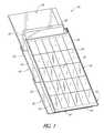
- FIG. 1is a top plan, left side, front view of an integrated composition shingle PV system
- FIG. 1Ashows a PV system of FIG. 1 surrounded by an integrated with composition shingles
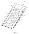
- FIG. 2is a top plan, left side, front view of the PV system of FIG. 1 ;
- FIG. 3is an enlarged view of a portion of the PV system of FIG. 2 ;
- FIG. 4is a top plan, right side, front view of the PV system of FIG. 1 ;
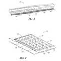
- FIG. 5is an enlarged view of a portion of the PV system of FIG. 1 ;
- FIG. 6is a top plan, left side, rear view of the PV system of FIG. 1 ;
- FIG. 7is an enlarged view of a portion of the PV system of FIG. 6 ;
- FIG. 8is an enlarged view of a portion of the PV system of FIG. 6 ;
- FIG. 9is a top plan, right side, rear view of the PV system of FIG. 1 ;
- FIG. 10is an enlarged view of a portion of the PV system of FIG. 9 ;
- FIG. 11is a bottom plan, front view of the PV system of FIG. 1 ;
- FIG. 12is a front elevational view of the PV system of FIG. 1 ;
- FIG. 13is a left side elevational view of the PV system of FIG. 1 ;
- FIG. 14is a right side elevational view of the PV system of FIG. 1 ;
- FIG. 15is a rear elevational view of the PV system of FIG. 1 .
- FIGS. 1-15are several views of an example of an integrated composition shingle photovoltaic (PV) system 10 .
- System 10is used with a composition shingle roofing installation of the type comprising generally flat, rectangular composition shingles 12 arranged in overlapping rows 16 on a support surface, typically a roofing surface 14 . See FIGS. 1 and 1A .
- System 10includes broadly a carrier 18 and a PV laminate 20 mounted to the carrier.
- Carrier 18is mountable on roofing surface 14 , typically using nails in a manner similar to conventional composition shingles.
- carrier 18is secured directly to roofing surface 14 without any shingles between the carrier and the roofing surface; in other examples PV system 10 and new rows 16 of shingles 12 can be mounted to a roofing surface covered by an existing layer of shingles.
- Carrier 18includes a PV laminate support region 22 , see FIGS. 1 and 11 , a left side edge 24 , a rear edge 26 , a right side edge 28 and a front edge 30 .
- the edges 24 - 30define a peripheral edge 32 surrounding support region 22 .
- Carrier 18also includes flashing 34 along the peripheral edge 32 , the flashing comprising left side flashing 36 , rear flashing 38 , right side flashing 40 and front flashing 42 along the left side, rear, right side and front edges 24 - 30 , respectively.
- Each system 10is typically secured to roofing surface 14 by nailing rear flashing 38 to the roofing surface.
- Front edge 30 of carrier 18in this example, overlies the entire front flashing 42 . In other examples front flashing 42 could extend outwardly beyond front edge 30 in a manner similar to that of rear flashing 38 .
- Rear flashing 38is positionable under a first row 44 of the overlapping rows 16 of composition shingles 12 .
- Left side flashing 36comprises left side flashing elements 52 interengageable with overlapping rows 46 , 48 of composition shingles 12 , the first row 44 of composition shingles overlapping the second row 46 of composition singles, the second row 46 of composition shingles 12 overlapping the third row 48 of composition shingles 12 , etc. See FIGS. 1A and 3 .
- right side flashing 36comprises right side flashing elements 54 (see FIG. 6 ) interengageable with overlapping rows 46 , 48 of composition shingles 12 .
- Left and right side flashing elements 52 , 54define gaps 55 therebetween (see FIGS. 3 and 5 ) to accommodate the interengagement.
- Front flashing 42is positionable on top of a row 50 of the overlapping rows 16 of composite shingles 12 .
- carrier 18includes a lower base 56 , and an upper PV laminate support member 58 supported above the base 56 by side supports 60 and interior supports 62 to define a ventilation region 64 between base 56 and support member 58 .
- Ventilation region 64provides a ventilation pathway between front edge 30 and rear edge 26 .
- Ventilation region 64has a height of about 1 inch to 4 inches. When it is desired to provide PV system 10 with a low-profile for enhanced aesthetics, the height of ventilation region 64 can be about 1 ⁇ 2 inch and still provide some cooling effect for PV laminate 20 . Ventilation region 64 also provides an open region for the passage of wires to effectively eliminate the need for creating holes in the roofing surface 14 . While it is generally preferred to provide a ventilation region 64 , in some situations it may be desired to eliminate the ventilation region (that is, the height of region 64 would be zero) so that PV laminate 20 is effectively flush with roofing surface 14 .
- a number of systems 10can be arranged adjacent to one another as an array of systems 10 .
- Systems 10can be arranged as rows of systems with the left side flashing elements 52 of one system 10 appropriately engaging the right side flashing elements 54 of an adjacent system 10 .
- internal supports 62are spaced apart from front edge 30 to create an open region 70 (see FIGS. 2 and 3 ) at the lower end of ventilation region 64 .
- rear edge 26has a complementary extension 68 sized to fit within open region 70 with front flashing 42 extending over and supported by rear flashing 38 . This inter-engagement helps to weatherproof the junction and permits one PV system 10 to counteract wind uplift forces exerted on adjacent PV system 10 .
- PV system 10is suitable for applications that involve either the installation of a new composition shingle roof over a bare roofing surface 14 , or installation over existing shingles 12 in conjunction with a re-roof that involves installation of new composition shingles over old ones (a complete re-roof). Installation on an existing composition shingle roof is possible but would require removal of shingles in the array area and care in tying in the waterproofing details in the carrier 18 , discussed above, to the remaining shingles. An important point is that the carrier 18 installs in the same manner as conventional composition shingles 12 , directly to the roofing surface 14 (whether a new roof or a re-roof). The carrier 18 performs several functions including the following.
- the carrier 18protects the PV laminate 20 in transport, handling, and in use like a conventional PV module frame.
- the flashing 34is integrated into the carrier 18 , so that composition shingles 12 can be installed around the array of PV systems 10 in a conventional manner while being properly overlapped and staggered to achieve waterproofing. No additional flashing is required.
- the PV system 10completely eliminates composition shingles 12 where the PV system is installed; it acts as the roof covering.
- the carrier 18can be attached to the roofing surface 14 conventionally as composition shingles are attached (such as with nails) and the penetrations waterproofed similarly (such as with overlapping shingles or another PV system). Thus mechanical attachment can be readily achieved by any roofer.
- the carrier 18can have a larger form factor than typical shingles, reducing cost.
- the carrier 18can be made in a number of form factors depending on end-use requirements.
- the carrier designallows for the PV laminate 20 to be located flush or substantially flush with the roofing surface 14 or at a chosen standoff distance above the roof to facilitate improved natural ventilation/cooling.
- This ventilation featureis integrated into the carrier 18 and designed to prevent entry of rain.
- the carrier 18can be designed with wire management features to allow on-roof electrical connection.
- This spacetypically 1 ⁇ 2′′ deep in the substantially flush embodiment also allows for some natural ventilation.
- the carrier 18can be made to be somewhat flexible, so roofing surface irregularities are easily accommodated. With a flexible PV laminate 20 , roofing surface irregularities will be no more evident than on a conventional shingled roof.
- the systemthen can be a Class A fire rated roof covering, whereas conventional modules attached on standoffs are typically Class C fire rated.
- PV systems 10can be designed to behave similarly in wind conditions as conventional composition shingles. That is, it is pressure equalizing and has a low aerodynamic profile. Not having to design for high design pressures allows for a much lighter weight structure.
- the carrier 18can be made from, for example, thermoformed, compression molded, or injection molded plastic, composite (plastic/glass), or sheet metal.
- the carrier 18incorporates flashing features 34 on all four sides to allow for seamless integration with the surrounding shingles. It also incorporates a ventilation region 64 between the PV laminate 20 and roofing surface 14 for wiring and ventilation. The installation permits flush installation with composition shingles without requiring in-attic wiring and incorporates some ventilation.
- the PV system 10provides true building integration in conjunction with asphalt shingles.
Landscapes
- Engineering & Computer Science (AREA)
- Architecture (AREA)
- Civil Engineering (AREA)
- Structural Engineering (AREA)
- Roof Covering Using Slabs Or Stiff Sheets (AREA)
Abstract
Description
Claims (12)
Priority Applications (1)
| Application Number | Priority Date | Filing Date | Title |
|---|---|---|---|
| US13/019,931US8215071B2 (en) | 2010-02-02 | 2011-02-02 | Integrated composition shingle PV system |
Applications Claiming Priority (2)
| Application Number | Priority Date | Filing Date | Title |
|---|---|---|---|
| US30075910P | 2010-02-02 | 2010-02-02 | |
| US13/019,931US8215071B2 (en) | 2010-02-02 | 2011-02-02 | Integrated composition shingle PV system |
Publications (2)
| Publication Number | Publication Date |
|---|---|
| US20110185652A1 US20110185652A1 (en) | 2011-08-04 |
| US8215071B2true US8215071B2 (en) | 2012-07-10 |
Family
ID=44340386
Family Applications (1)
| Application Number | Title | Priority Date | Filing Date |
|---|---|---|---|
| US13/019,931ActiveUS8215071B2 (en) | 2010-02-02 | 2011-02-02 | Integrated composition shingle PV system |
Country Status (1)
| Country | Link |
|---|---|
| US (1) | US8215071B2 (en) |
Cited By (20)
| Publication number | Priority date | Publication date | Assignee | Title |
|---|---|---|---|---|
| US20100242381A1 (en)* | 2009-03-24 | 2010-09-30 | Jenkins Robert L | Photovoltaic systems, methods for installing photovoltaic systems, and kits for installing photovoltaic systems |
| US20130111831A1 (en)* | 2011-11-03 | 2013-05-09 | Robert L. Jenkins | Photovoltaic Roofing Systems And Methods For Repairing Them |
| US20140083028A1 (en)* | 2011-05-10 | 2014-03-27 | Robert Richardson | Roof solar panel for conventional sloping roof and shingle integration |
| US20150083197A1 (en)* | 2011-07-29 | 2015-03-26 | Dow Global Technologies Llc | Interface system and method for photovoltaic cladding to standard cladding |
| US9825582B2 (en) | 2015-12-30 | 2017-11-21 | Cogitur, Inc. | Roofing panels with integrated photovoltaic cells and method of installation |
| USD822890S1 (en) | 2016-09-07 | 2018-07-10 | Felxtronics Ap, Llc | Lighting apparatus |
| USD832494S1 (en) | 2017-08-09 | 2018-10-30 | Flex Ltd. | Lighting module heatsink |
| USD832495S1 (en) | 2017-08-18 | 2018-10-30 | Flex Ltd. | Lighting module locking mechanism |
| USD833061S1 (en) | 2017-08-09 | 2018-11-06 | Flex Ltd. | Lighting module locking endcap |
| US10256765B2 (en) | 2013-06-13 | 2019-04-09 | Building Materials Investment Corporation | Roof integrated photovoltaic system |
| USD846793S1 (en) | 2017-08-09 | 2019-04-23 | Flex Ltd. | Lighting module locking mechanism |
| USD862778S1 (en) | 2017-08-22 | 2019-10-08 | Flex Ltd | Lighting module lens |
| USD862777S1 (en) | 2017-08-09 | 2019-10-08 | Flex Ltd. | Lighting module wide distribution lens |
| USD872319S1 (en) | 2017-08-09 | 2020-01-07 | Flex Ltd. | Lighting module LED light board |
| USD877964S1 (en) | 2017-08-09 | 2020-03-10 | Flex Ltd. | Lighting module |
| USD888323S1 (en) | 2017-09-07 | 2020-06-23 | Flex Ltd | Lighting module wire guard |
| US10775030B2 (en) | 2017-05-05 | 2020-09-15 | Flex Ltd. | Light fixture device including rotatable light modules |
| US11444569B2 (en)* | 2020-10-14 | 2022-09-13 | GAF Energy LLC | Mounting apparatus for photovoltaic modules |
| US11834835B2 (en) | 2020-03-30 | 2023-12-05 | Bmic Llc | Interlocking laminated structural roofing panels |
| US11855580B2 (en) | 2020-11-09 | 2023-12-26 | Bmic Llc | Interlocking structural roofing panels with integrated solar panels |
Families Citing this family (7)
| Publication number | Priority date | Publication date | Assignee | Title |
|---|---|---|---|---|
| US8511006B2 (en) | 2009-07-02 | 2013-08-20 | Owens Corning Intellectual Capital, Llc | Building-integrated solar-panel roof element systems |
| US8677702B2 (en) | 2010-09-28 | 2014-03-25 | Certainteed Corporation | Photovoltaic systems, methods for installing photovoltaic systems, and kits for installing photovoltaic systems |
| US8782972B2 (en) | 2011-07-14 | 2014-07-22 | Owens Corning Intellectual Capital, Llc | Solar roofing system |
| US11060766B2 (en)* | 2018-05-08 | 2021-07-13 | Thomas S. Martin | Smart roof system and method |
| US11527990B2 (en) | 2019-02-20 | 2022-12-13 | Sunpower Corporation | Aggregated photovoltaic panels |
| CN115233912B (en)* | 2022-08-09 | 2024-01-02 | 江苏新阳光智顶科技有限公司 | Roof BIPV system |
| GB2638658A (en)* | 2024-01-10 | 2025-09-03 | Senergy Innovations Ltd | In-roof solar-thermal-panel frame and system |
Citations (25)
| Publication number | Priority date | Publication date | Assignee | Title |
|---|---|---|---|---|
| US359959A (en) | 1887-03-22 | Metallic shingle or roofing-plate | ||
| US3769091A (en) | 1972-03-31 | 1973-10-30 | Us Navy | Shingled array of solar cells |
| US4040867A (en) | 1976-08-24 | 1977-08-09 | The United States Of America As Represented By The Administrator Of The National Aeronautics And Space Administration | Solar cell shingle |
| US4936063A (en) | 1989-05-19 | 1990-06-26 | Humphrey John B | Frame flanges for mounting photovoltaic modules direct to roof structural framing |
| US5056288A (en) | 1985-09-26 | 1991-10-15 | Motokatsu Funaki | Roof structure and fixture therefor |
| US5112408A (en) | 1990-01-31 | 1992-05-12 | Bmc Melchior Solartechnik Kg | Roofing tile assembly |
| US5232518A (en) | 1990-11-30 | 1993-08-03 | United Solar Systems Corporation | Photovoltaic roof system |
| US5575861A (en) | 1993-12-30 | 1996-11-19 | United Solar Systems Corporation | Photovoltaic shingle system |
| US5590495A (en) | 1995-07-06 | 1997-01-07 | Bressler Group Inc. | Solar roofing system |
| US5613337A (en) | 1994-03-25 | 1997-03-25 | Vail Metal Systems, Llc | Metal shingle with gutter and interlocking edges |
| US5746839A (en)* | 1996-04-08 | 1998-05-05 | Powerlight Corporation | Lightweight, self-ballasting photovoltaic roofing assembly |
| US5968287A (en) | 1997-05-16 | 1999-10-19 | United Solar Systems Corporation | Power generating building panels and methods for their manufacture |
| US5990414A (en) | 1996-09-23 | 1999-11-23 | Posnansky; Mario | Photovoltaic solar roof |
| US6173546B1 (en) | 1998-08-28 | 2001-01-16 | James P Schafer | Interlocking metal shingle |
| US6463708B1 (en) | 1999-11-15 | 2002-10-15 | Victor W. Anderson | Roof shingle and system |
| US20030154667A1 (en) | 2002-02-20 | 2003-08-21 | Dinwoodie Thomas L. | Shingle system |
| US20030154666A1 (en) | 2002-02-20 | 2003-08-21 | Dinwoodie Thomas L. | Shingle system and method |
| US20060266405A1 (en) | 2005-05-27 | 2006-11-30 | Powerlight Corporation, A California Corporation | Fire resistant PV shingle assembly |
| US7155870B2 (en) | 2004-06-18 | 2007-01-02 | Powerlight Corp. | Shingle assembly with support bracket |
| US7178295B2 (en) | 2002-02-20 | 2007-02-20 | Powerlight Corporation | Shingle assembly |
| US20070251567A1 (en)* | 2004-02-13 | 2007-11-01 | Plaisted Joshua R | Interconnected solar module design and system |
| US20080190047A1 (en)* | 2007-02-08 | 2008-08-14 | Allen Gary E | Solar Panel Roof Kit |
| US20080313976A1 (en)* | 2007-02-08 | 2008-12-25 | Luma Resources, Llc | Solar Panel Roof Kit |
| US20100313499A1 (en)* | 2009-06-10 | 2010-12-16 | Gangemi Ronald J | Roof mounting bracket for photovoltaic power generation system |
| US20100313501A1 (en)* | 2009-06-10 | 2010-12-16 | Gangemi Ronald J | Roof mounting bracket for photovoltaic power generation system |
- 2011
- 2011-02-02USUS13/019,931patent/US8215071B2/enactiveActive
Patent Citations (26)
| Publication number | Priority date | Publication date | Assignee | Title |
|---|---|---|---|---|
| US359959A (en) | 1887-03-22 | Metallic shingle or roofing-plate | ||
| US3769091A (en) | 1972-03-31 | 1973-10-30 | Us Navy | Shingled array of solar cells |
| US4040867A (en) | 1976-08-24 | 1977-08-09 | The United States Of America As Represented By The Administrator Of The National Aeronautics And Space Administration | Solar cell shingle |
| US5056288A (en) | 1985-09-26 | 1991-10-15 | Motokatsu Funaki | Roof structure and fixture therefor |
| US4936063A (en) | 1989-05-19 | 1990-06-26 | Humphrey John B | Frame flanges for mounting photovoltaic modules direct to roof structural framing |
| US5112408A (en) | 1990-01-31 | 1992-05-12 | Bmc Melchior Solartechnik Kg | Roofing tile assembly |
| US5232518A (en) | 1990-11-30 | 1993-08-03 | United Solar Systems Corporation | Photovoltaic roof system |
| US5575861A (en) | 1993-12-30 | 1996-11-19 | United Solar Systems Corporation | Photovoltaic shingle system |
| US5613337A (en) | 1994-03-25 | 1997-03-25 | Vail Metal Systems, Llc | Metal shingle with gutter and interlocking edges |
| US5590495A (en) | 1995-07-06 | 1997-01-07 | Bressler Group Inc. | Solar roofing system |
| US5746839A (en)* | 1996-04-08 | 1998-05-05 | Powerlight Corporation | Lightweight, self-ballasting photovoltaic roofing assembly |
| US5990414A (en) | 1996-09-23 | 1999-11-23 | Posnansky; Mario | Photovoltaic solar roof |
| US5968287A (en) | 1997-05-16 | 1999-10-19 | United Solar Systems Corporation | Power generating building panels and methods for their manufacture |
| US6173546B1 (en) | 1998-08-28 | 2001-01-16 | James P Schafer | Interlocking metal shingle |
| US6463708B1 (en) | 1999-11-15 | 2002-10-15 | Victor W. Anderson | Roof shingle and system |
| US7178295B2 (en) | 2002-02-20 | 2007-02-20 | Powerlight Corporation | Shingle assembly |
| US20030154667A1 (en) | 2002-02-20 | 2003-08-21 | Dinwoodie Thomas L. | Shingle system |
| US20030154666A1 (en) | 2002-02-20 | 2003-08-21 | Dinwoodie Thomas L. | Shingle system and method |
| US6883290B2 (en) | 2002-02-20 | 2005-04-26 | Powerlight Corporation | Shingle system and method |
| US20070251567A1 (en)* | 2004-02-13 | 2007-11-01 | Plaisted Joshua R | Interconnected solar module design and system |
| US7155870B2 (en) | 2004-06-18 | 2007-01-02 | Powerlight Corp. | Shingle assembly with support bracket |
| US20060266405A1 (en) | 2005-05-27 | 2006-11-30 | Powerlight Corporation, A California Corporation | Fire resistant PV shingle assembly |
| US20080190047A1 (en)* | 2007-02-08 | 2008-08-14 | Allen Gary E | Solar Panel Roof Kit |
| US20080313976A1 (en)* | 2007-02-08 | 2008-12-25 | Luma Resources, Llc | Solar Panel Roof Kit |
| US20100313499A1 (en)* | 2009-06-10 | 2010-12-16 | Gangemi Ronald J | Roof mounting bracket for photovoltaic power generation system |
| US20100313501A1 (en)* | 2009-06-10 | 2010-12-16 | Gangemi Ronald J | Roof mounting bracket for photovoltaic power generation system |
Non-Patent Citations (3)
| Title |
|---|
| Dow Building Solutions; Dow Powerhouse; 2 pages; Jan. 19, 2010. |
| Sharp 62 Watt Shingle Panel product description; from www.spheralsolar.com; found Jan. 2, 2010; 2 pages. |
| Uni-Solar, ovonics@work; Solar Shingles SHR-17 Sell Sheet; copyright 2004 United Solar Ovonic; 2 pages. |
Cited By (34)
| Publication number | Priority date | Publication date | Assignee | Title |
|---|---|---|---|---|
| US8966838B2 (en) | 2009-03-24 | 2015-03-03 | Certainteed Corporation | Photovoltaic systems, methods for installing photovoltaic systems, and kits for installing photovoltaic systems |
| US20100242381A1 (en)* | 2009-03-24 | 2010-09-30 | Jenkins Robert L | Photovoltaic systems, methods for installing photovoltaic systems, and kits for installing photovoltaic systems |
| US8646228B2 (en)* | 2009-03-24 | 2014-02-11 | Certainteed Corporation | Photovoltaic systems, methods for installing photovoltaic systems, and kits for installing photovoltaic systems |
| US20140083028A1 (en)* | 2011-05-10 | 2014-03-27 | Robert Richardson | Roof solar panel for conventional sloping roof and shingle integration |
| US8991116B2 (en)* | 2011-05-10 | 2015-03-31 | Robert Richardson | Roof solar panel for conventional sloping roof and shingle integration |
| US20150083197A1 (en)* | 2011-07-29 | 2015-03-26 | Dow Global Technologies Llc | Interface system and method for photovoltaic cladding to standard cladding |
| US9537033B2 (en)* | 2011-07-29 | 2017-01-03 | Dow Global Technologies Llc | Interface system and method for photovoltaic cladding to standard cladding |
| US8863451B2 (en)* | 2011-11-03 | 2014-10-21 | Certainteed Corporation | Photovoltaic roofing systems and methods for repairing them |
| US20130111831A1 (en)* | 2011-11-03 | 2013-05-09 | Robert L. Jenkins | Photovoltaic Roofing Systems And Methods For Repairing Them |
| US10256765B2 (en) | 2013-06-13 | 2019-04-09 | Building Materials Investment Corporation | Roof integrated photovoltaic system |
| US9825582B2 (en) | 2015-12-30 | 2017-11-21 | Cogitur, Inc. | Roofing panels with integrated photovoltaic cells and method of installation |
| USD822890S1 (en) | 2016-09-07 | 2018-07-10 | Felxtronics Ap, Llc | Lighting apparatus |
| US10775030B2 (en) | 2017-05-05 | 2020-09-15 | Flex Ltd. | Light fixture device including rotatable light modules |
| USD885615S1 (en) | 2017-08-09 | 2020-05-26 | Flex Ltd. | Lighting module LED light board |
| USD832494S1 (en) | 2017-08-09 | 2018-10-30 | Flex Ltd. | Lighting module heatsink |
| USD846793S1 (en) | 2017-08-09 | 2019-04-23 | Flex Ltd. | Lighting module locking mechanism |
| USD1010915S1 (en) | 2017-08-09 | 2024-01-09 | Linmore Labs Led, Inc. | Lighting module |
| USD853625S1 (en) | 2017-08-09 | 2019-07-09 | Flex Ltd | Lighting module heatsink |
| USD853629S1 (en) | 2017-08-09 | 2019-07-09 | Flex Ltd | Lighting module locking mechanism |
| USD853627S1 (en) | 2017-08-09 | 2019-07-09 | Flex Ltd | Lighting module locking endcap |
| USD905325S1 (en) | 2017-08-09 | 2020-12-15 | Flex Ltd | Lighting module |
| USD862777S1 (en) | 2017-08-09 | 2019-10-08 | Flex Ltd. | Lighting module wide distribution lens |
| USD872319S1 (en) | 2017-08-09 | 2020-01-07 | Flex Ltd. | Lighting module LED light board |
| USD877964S1 (en) | 2017-08-09 | 2020-03-10 | Flex Ltd. | Lighting module |
| USD833061S1 (en) | 2017-08-09 | 2018-11-06 | Flex Ltd. | Lighting module locking endcap |
| USD832495S1 (en) | 2017-08-18 | 2018-10-30 | Flex Ltd. | Lighting module locking mechanism |
| USD853628S1 (en) | 2017-08-18 | 2019-07-09 | Flex Ltd. | Lighting module locking mechanism |
| USD862778S1 (en) | 2017-08-22 | 2019-10-08 | Flex Ltd | Lighting module lens |
| USD888323S1 (en) | 2017-09-07 | 2020-06-23 | Flex Ltd | Lighting module wire guard |
| US11834835B2 (en) | 2020-03-30 | 2023-12-05 | Bmic Llc | Interlocking laminated structural roofing panels |
| US11444569B2 (en)* | 2020-10-14 | 2022-09-13 | GAF Energy LLC | Mounting apparatus for photovoltaic modules |
| US11689149B2 (en) | 2020-10-14 | 2023-06-27 | GAF Energy LLC | Mounting apparatus for photovoltaic modules |
| US12255575B2 (en) | 2020-10-14 | 2025-03-18 | GAF Energy LLC | Mounting apparatus for photovoltaic modules |
| US11855580B2 (en) | 2020-11-09 | 2023-12-26 | Bmic Llc | Interlocking structural roofing panels with integrated solar panels |
Also Published As
| Publication number | Publication date |
|---|---|
| US20110185652A1 (en) | 2011-08-04 |
Similar Documents
| Publication | Publication Date | Title |
|---|---|---|
| US8215071B2 (en) | Integrated composition shingle PV system | |
| US9716465B2 (en) | Photovoltaic array with array-roof integration member | |
| JP6786489B2 (en) | Roof, exterior or siding equipment | |
| JP6692375B2 (en) | Solar cell module and roof structure | |
| EP1476617B1 (en) | Shingle system | |
| US10778139B2 (en) | Building integrated photovoltaic system with glass photovoltaic tiles | |
| EP1476614B1 (en) | Shingle system and method for mounting the same | |
| US8701360B2 (en) | Method and apparatus for assembling photovoltaic modules | |
| US8186111B2 (en) | Profile roof tile with integrated photovoltaic module | |
| US8677702B2 (en) | Photovoltaic systems, methods for installing photovoltaic systems, and kits for installing photovoltaic systems | |
| US20190028054A1 (en) | Building integrated photovoltaic tile mounting system | |
| US20060000178A1 (en) | Shingle assembly with support bracket | |
| US10749460B2 (en) | Solar shingle roofing kit | |
| CN110915132A (en) | Multi-zone solar roof laying module | |
| JP2006500488A (en) | Roofing board assembly | |
| WO2011002433A1 (en) | Spanish shingles with photovoltaic cells, method of producing and method of installation | |
| US20140090320A1 (en) | Innovative batten system for roof tile installation | |
| US10879842B2 (en) | Roofing, cladding or siding module or apparatus | |
| JP2006274659A (en) | Installation structure of solar power generator | |
| GB2454948A (en) | Roof Tile Support Bracket | |
| EP2557605A3 (en) | Roof-mounted solar panels | |
| HK40026535A (en) | Multi-region solar roofing modules | |
| AU2013204709A1 (en) | Solar sheeting for roofing or walling |
Legal Events
| Date | Code | Title | Description |
|---|---|---|---|
| AS | Assignment | Owner name:SUNPOWER CORPORATION, CALIFORNIA Free format text:ASSIGNMENT OF ASSIGNORS INTEREST;ASSIGNOR:LENOX, CARL J.S.;REEL/FRAME:026381/0231 Effective date:20110517 | |
| STCF | Information on status: patent grant | Free format text:PATENTED CASE | |
| FPAY | Fee payment | Year of fee payment:4 | |
| FEPP | Fee payment procedure | Free format text:PAYOR NUMBER ASSIGNED (ORIGINAL EVENT CODE: ASPN); ENTITY STATUS OF PATENT OWNER: LARGE ENTITY Free format text:PAYER NUMBER DE-ASSIGNED (ORIGINAL EVENT CODE: RMPN); ENTITY STATUS OF PATENT OWNER: LARGE ENTITY | |
| MAFP | Maintenance fee payment | Free format text:PAYMENT OF MAINTENANCE FEE, 8TH YEAR, LARGE ENTITY (ORIGINAL EVENT CODE: M1552); ENTITY STATUS OF PATENT OWNER: LARGE ENTITY Year of fee payment:8 | |
| AS | Assignment | Owner name:BANK OF AMERICA, N.A., AS AGENT, NORTH CAROLINA Free format text:SECURITY INTEREST;ASSIGNOR:SUNPOWER CORPORATION;REEL/FRAME:061422/0566 Effective date:20220912 | |
| MAFP | Maintenance fee payment | Free format text:PAYMENT OF MAINTENANCE FEE, 12TH YEAR, LARGE ENTITY (ORIGINAL EVENT CODE: M1553); ENTITY STATUS OF PATENT OWNER: LARGE ENTITY Year of fee payment:12 | |
| AS | Assignment | Owner name:GLAS AMERICAS LLC, AS COLLATERAL AGENT, NEW JERSEY Free format text:SECOND LIEN PATENT SECURITY AGREEMENT;ASSIGNOR:SUNPOWER CORPORATION;REEL/FRAME:066598/0964 Effective date:20240214 | |
| AS | Assignment | Owner name:UNIRAC, INC., NEW MEXICO Free format text:RELEASE BY SECURED PARTY;ASSIGNOR:SUNPOWER CORPORATION,;REEL/FRAME:070704/0860 Effective date:20241018 | |
| AS | Assignment | Owner name:UNIRAC, INC., NEW MEXICO Free format text:ASSIGNMENT OF ASSIGNORS INTEREST;ASSIGNORS:SUNPOWER CORPORATION;SUNPOWER CORPORATION, SYSTEMS;REEL/FRAME:071302/0904 Effective date:20241021 |