US8213816B2 - Method and system for banding compensation using electrostatic voltmeter based sensing - Google Patents
Method and system for banding compensation using electrostatic voltmeter based sensingDownload PDFInfo
- Publication number
- US8213816B2 US8213816B2US12/549,095US54909509AUS8213816B2US 8213816 B2US8213816 B2US 8213816B2US 54909509 AUS54909509 AUS 54909509AUS 8213816 B2US8213816 B2US 8213816B2
- Authority
- US
- United States
- Prior art keywords
- image
- quality defect
- image quality
- bearing surface
- esv
- Prior art date
- Legal status (The legal status is an assumption and is not a legal conclusion. Google has not performed a legal analysis and makes no representation as to the accuracy of the status listed.)
- Expired - Fee Related, expires
Links
- 238000000034methodMethods0.000titleclaimsabstractdescription83
- 230000007547defectEffects0.000claimsabstractdescription122
- 238000007639printingMethods0.000claimsabstractdescription51
- 238000012546transferMethods0.000claimsabstractdescription35
- 230000008569processEffects0.000claimsabstractdescription24
- 238000009825accumulationMethods0.000claimsabstractdescription12
- 238000007599dischargingMethods0.000claimsabstractdescription9
- 230000001678irradiating effectEffects0.000claimsabstractdescription9
- 108091008695photoreceptorsProteins0.000claimsdescription27
- 238000000926separation methodMethods0.000claimsdescription23
- 241000362773Espirito Santo virusSpecies0.000claimsdescription19
- 238000012360testing methodMethods0.000claimsdescription15
- 238000012937correctionMethods0.000claimsdescription8
- 238000011161developmentMethods0.000claimsdescription7
- 238000005259measurementMethods0.000description15
- 230000006870functionEffects0.000description9
- 230000035945sensitivityEffects0.000description6
- 239000002245particleSubstances0.000description5
- 238000004140cleaningMethods0.000description4
- 230000000737periodic effectEffects0.000description4
- 239000000843powderSubstances0.000description4
- 230000001360synchronised effectEffects0.000description4
- 230000008859changeEffects0.000description3
- 239000000463materialSubstances0.000description3
- 230000003247decreasing effectEffects0.000description2
- 238000001739density measurementMethods0.000description2
- 230000006872improvementEffects0.000description2
- 239000007788liquidSubstances0.000description2
- 230000003287optical effectEffects0.000description2
- 238000012545processingMethods0.000description2
- 230000009467reductionEffects0.000description2
- 239000000758substrateSubstances0.000description2
- 230000006978adaptationEffects0.000description1
- 230000009286beneficial effectEffects0.000description1
- 230000015572biosynthetic processEffects0.000description1
- 230000015556catabolic processEffects0.000description1
- 239000003086colorantSubstances0.000description1
- 238000004891communicationMethods0.000description1
- 239000000470constituentSubstances0.000description1
- 238000011109contaminationMethods0.000description1
- 238000000354decomposition reactionMethods0.000description1
- 238000006731degradation reactionMethods0.000description1
- 230000000694effectsEffects0.000description1
- 238000005516engineering processMethods0.000description1
- 239000008187granular materialSubstances0.000description1
- 230000003993interactionEffects0.000description1
- 238000013507mappingMethods0.000description1
- 238000012986modificationMethods0.000description1
- 230000004048modificationEffects0.000description1
- 239000002699waste materialSubstances0.000description1
Images


Classifications
- G—PHYSICS
- G03—PHOTOGRAPHY; CINEMATOGRAPHY; ANALOGOUS TECHNIQUES USING WAVES OTHER THAN OPTICAL WAVES; ELECTROGRAPHY; HOLOGRAPHY
- G03G—ELECTROGRAPHY; ELECTROPHOTOGRAPHY; MAGNETOGRAPHY
- G03G15/00—Apparatus for electrographic processes using a charge pattern
- G03G15/04—Apparatus for electrographic processes using a charge pattern for exposing, i.e. imagewise exposure by optically projecting the original image on a photoconductive recording material
- G03G15/043—Apparatus for electrographic processes using a charge pattern for exposing, i.e. imagewise exposure by optically projecting the original image on a photoconductive recording material with means for controlling illumination or exposure
- G—PHYSICS
- G03—PHOTOGRAPHY; CINEMATOGRAPHY; ANALOGOUS TECHNIQUES USING WAVES OTHER THAN OPTICAL WAVES; ELECTROGRAPHY; HOLOGRAPHY
- G03G—ELECTROGRAPHY; ELECTROPHOTOGRAPHY; MAGNETOGRAPHY
- G03G15/00—Apparatus for electrographic processes using a charge pattern
- G03G15/50—Machine control of apparatus for electrographic processes using a charge pattern, e.g. regulating differents parts of the machine, multimode copiers, microprocessor control
- G03G15/5033—Machine control of apparatus for electrographic processes using a charge pattern, e.g. regulating differents parts of the machine, multimode copiers, microprocessor control by measuring the photoconductor characteristics, e.g. temperature, or the characteristics of an image on the photoconductor
- G03G15/5037—Machine control of apparatus for electrographic processes using a charge pattern, e.g. regulating differents parts of the machine, multimode copiers, microprocessor control by measuring the photoconductor characteristics, e.g. temperature, or the characteristics of an image on the photoconductor the characteristics being an electrical parameter, e.g. voltage
Definitions
- the present disclosurerelates to a method and system for compensating for image quality defects using an Electrostatic Voltmeter (ESV).
- ESVElectrostatic Voltmeter
- An electrophotographic, or xerographic, image printing systememploys an image bearing surface, such as a photoreceptor drum or belt, which is charged to a substantially uniform potential so as to sensitize the surface thereof.
- the charged portion of the image bearing surfaceis exposed to a light image of an original document being reproduced.
- Exposure of the charged image bearing surfaceselectively dissipates the charge thereon in the irradiated areas to record an electrostatic latent image on the image bearing surface corresponding to the image contained within the original document.
- the location of the electrical charge forming the latent imageis usually optically controlled. More specifically, in a digital xerographic system, the formation of the latent image is controlled by a raster output scanning device, usually a laser or LED source.
- the latent imageis developed by bringing a developer material into contact therewith.
- the electrostatic latent imageis developed with dry developer material comprising carrier granules having toner particles adhering triboelectrically thereto.
- a liquid developer materialmay be used as well.
- the toner particlesare attracted to the latent image, forming a visible powder image on the image bearing surface.
- the toner powder imageis transferred to a media, such as sheets, paper or other substrate sheets, using pressure and heat to fuse the toner image to the media to form a print.
- the image printing systemgenerally has two important dimensions: a process (or a slow scan) direction and a cross-process (or a fast scan) direction.
- a processor a slow scan direction
- a cross-processor a fast scan direction.
- the direction in which an image bearing surface movesis referred to as the process (or the slow scan) direction
- the direction perpendicular to the process (or the slow scan) directionis referred to as the cross-process (or the fast scan) direction.
- Electrophotographic image printing systems of this typemay produce color prints using a plurality of stations.
- Each stationhas a charging device for charging the image bearing surface, an exposing device for selectively illuminating the charged portions of the image bearing surface to record an electrostatic latent image thereon, and a developer unit for developing the electrostatic latent image with toner particles.
- Each developer unitdeposits different color toner particles on the respective electrostatic latent image.
- the imagesare developed, at least partially in superimposed registration with one another, to form a multi-color toner powder image.
- the resultant multi-color powder imageis subsequently transferred to a media.
- the transferred multicolor imageis then permanently fused to the media forming the color print.
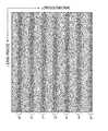
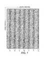
- Bandinggenerally refers to periodic defects on an image caused by a one-dimensional density variation in the process (slow scan) direction.
- An example of this kind of image quality defect, periodic bandingis illustrated in FIG. 1 .
- bandsexist in columns 1 a , 1 b , 1 c , 1 d , 1 e , 1 f and 1 g .
- Banding in a xerographic enginemay be caused by charge non-uniformity on the image bearing surface, variations in a Photo Induced Discharge Curve (PIDC), image bearing surface motion quality variations, and/or image bearing surface “out-of-round” that lead to periodic non-uniformities manifesting in the output print.
- PIDCPhoto Induced Discharge Curve
- the PIDCmay be defined as a plot of surface potential of the image bearing surface as a function of incident light exposure.
- Image bearing surface motion quality variationmay be defined as imperfections in the motion of the image bearing surface causing the instantaneous position of the image bearing surface to be less than ideal. Image bearing surface motion quality variations may be caused by vibration, motion backlash, gear train interactions, mechanical imbalances, friction, among other factors. Image bearing surface out-of-round may be defined as variations in the diameter of the image bearing surface, such as a photoreceptor drum, causing the image bearing surface to not be perfectly round.
- ADCAutomatic Density Control
- a densitometermeasures the degree of darkness for an image.
- an ADC sensormay measure the light reflected from the toner image on an intermediate transfer belt, and supplies a voltage value corresponding to the measured amount of light to a controller.
- SNRsignal-to-noise ratio
- a method for compensating for an image quality defect in an image printing systemcomprising at least one marking engine, the at least one marking station comprising a charging device for charging the image bearing surface, an exposing device for irradiating and discharging the image bearing surface to form a latent image, a developer unit for developing toner to the image bearing surface, and a transfer unit for transferring toner from the image bearing surface to an image accumulation surface.
- the methodincludes sensing the image quality defect on an image bearing surface by an electrostatic voltmeter (ESV) in the image printing system; determining the frequency, amplitude, and/or phase of the image quality defect by a processor; and compensating for the image quality defect by modulating the power of the exposing device during an expose process.
- ESVelectrostatic voltmeter
- a method for compensating for an image quality defect in an image printing systemcomprising at least one marking station comprising a charging device for charging the image bearing surface, an exposing device for irradiating and discharging the image bearing surface to form a latent image, a developer unit for developing toner to the image bearing surface, and a transfer unit for transferring toner from the image bearing surface to an image accumulation surface.
- the methodincludes sensing the image quality defect on an image bearing surface by an electrostatic voltmeter (ESV) in the image printing system; determining the frequency, amplitude, and/or phase of the image quality defect by a processor; and compensating for the image quality defect by modifying image content.
- ESVelectrostatic voltmeter
- a system for compensating for an image quality defect in an image printing systemincludes a marking engine; an electrostatic voltmeter (ESV) configured to sense the image quality defect on an image bearing surface; a processor, wherein the processor is configured to determine the frequency, amplitude, and/or phase of the banding defect based on readings of the ESV; and a controller, wherein the controller is configured to compensate for the image quality defect by modulating power of the exposing device during an expose process.
- ESVelectrostatic voltmeter
- a system for compensating for an image quality defect in an image printing systemincludes a marking engine; an electrostatic voltmeter (ESV) configured to sense the image quality defect on an image bearing surface; a processor, wherein the processor is configured to determine the frequency, amplitude, and/or phase of the banding defect based on readings of the ESV; and a controller, wherein the controller is configured to compensate for the image quality defect by modifying image content.
- ESVelectrostatic voltmeter
- FIG. 1illustrates banding in the process direction
- FIG. 2illustrates an image printing system employing ESV based sensing to compensate for image quality defects
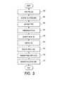
- FIG. 3illustrates one embodiment of a method for digitally modifying the image content data employing ESV based sensing to compensate for image quality defects
- FIG. 4illustrates one embodiment of a method of calibrating tone reproduction curves (TRCs) in accordance with an embodiment
- FIG. 5illustrates an image reflectance profile sensed by a sensor, with an equation for measuring the corresponding signal-to-noise ratio
- FIG. 6illustrates normalized signals sensed by a sensor sensing the output print, an ESV sensor, and an ADC sensor, an the corresponding signal-to-noise ratios
- FIG. 7illustrates one embodiment of a method for compensating for a banding defect using ESV based sensing.
- the present disclosureaddresses an issue in the area of banding correction.
- the present disclosureproposes a use of Electrostatic Voltmeter (ESV) sensors to measure charge density variation, or voltage non-uniformity, on the image bearing surface to sense periodic image quality defects.
- Image quality defectssuch as banding defects, may be caused by charge non-uniformity, variations in the Photo Induced Discharge Curve (PIDC), image bearing surface motion quality variations, and/or image bearing surface “out-of-round.”
- PIDCPhoto Induced Discharge Curve
- the present disclosureproposes compensating for the image quality defects by generating a compensation signal.
- the compensation signalmay modulate power of an exposing device, such as a Raster Output Scanner (ROS), during the expose process.
- ROSRaster Output Scanner
- the compensation signalmay modify image content.
- Such an embodimentmay have a marking engine with an image bearing surface that is synchronous with the printed pages such that each page starts at substantially the same point on the image bearing surface circumference.
- ESV sensorsmay yield a less noisy signal because fewer noise sources contribute to its signal as compared to ADC sensors, thus requiring fewer test patch measurements and reducing the time required for banding compensation.
- FIG. 2illustrates one embodiment of a multicolor image printing system 10 incorporating an embodiment.
- One embodimentmay be the Xerox DocuColor 8000®.
- an “intermediate-belt-transfer” xerographic color image printing systemin which successive primary-color (e.g., C, M, Y, K) images are accumulated on image bearing surface 12 C, 12 M, 12 Y, and 12 K.
- Each image bearing surface 12 C, 12 M, 12 Y, and 12 Kin turn transfers the images to an intermediate transfer member 30 .
- any image printing machinesuch as monochrome machines using any technology, machines that print on photosensitive substrates, xerographic machines with multiple photoreceptors, “image-on-image” xerographic color image printing systems (e.g., U.S. Pat. No. 7,177,585, herein incorporated by reference in its entirety), Tightly Integrated Parallel Printing (TIPP) systems (e.g. U.S. Pat. Nos. 7,024,152 and 7,136,616, each of which herein incorporated by reference in its entirety), or liquid ink electrophotographic machines, may utilize the present disclosure as well.
- TIPPTightly Integrated Parallel Printing
- the image printing system 10includes marking stations 11 C, 11 M, 11 Y, and 11 K (collectively referred to as 11 ) arranged in series for successive color separations (e.g., C, M, Y, and K).
- Each print station 11includes an image bearing surface with a charging device, an exposing device, a developer device, an ESV and a cleaning device disposed around its periphery.
- printing station 11 Cincludes image bearing surface 12 C, charging device 14 C, exposing device 16 C, developer device 18 C, ESV 22 C, transfer device 24 C, and cleaning device 20 C.
- Transfer device 24 Cmay be a Bias Transfer Roll, as shown in FIG. 1 of U.S. Pat. No. 5,321,476, herein incorporated by reference in its entirety.
- a single color toner image formed on first image bearing surface 12 Cis transferred to intermediate transfer member 30 by first transfer device 24 C.
- Intermediate transfer member 30is wrapped around rollers 50 , 52 which are driven to move intermediate transfer member 30 in the direction of arrow 36 .
- the successive color separationsare built up in a superimposed manner on the surface of the intermediate transfer member 30 , and then the image is transferred from the intermediate transfer member (e.g., at transfer station 80 ) to an image accumulation surface 70 , such as a document, to form a printed image on the document.
- the imageis then fused to document 70 by fuser 82 .
- the exposing devices 16 C, 16 M, 16 Y, and 16 Kmay be one or more Raster Output Scanner (ROS) to expose the charged portions of the image bearing surface 12 C, 12 M, 12 Y, and 12 K to record an electrostatic latent image on the image bearing surface 12 C, 12 M, 12 Y, and 12 K.
- ROSRaster Output Scanner
- ESVs 22 C, 22 M, 22 Y, and 22 Kare configured to sense a charge density variation, or voltage non-uniformity, on the surface of image bearing surfaces 12 C, 12 M, 12 Y, and 12 K, (collectively referred to as 12 ) respectively.
- ESVssee, e.g., U.S. Pat. Nos. 6,806,717, 5,270,660; 5,119,131; and 4,786,858, each of which herein incorporated by reference in its entirety.
- ESVs 22 C, 22 M, 22 Y, and 22 Kare located after exposing devices 16 C, 16 M, 16 Y, and 16 K, respectively, and before developer devices 18 C, 18 M, 18 Y, and 18 K, respectively.
- an array of ESVsmay be arranged in the cross-process direction to enable measurement of banding amplitude variation across the cross-process direction. This would be particularly beneficial in a synchronous photoreceptor embodiment using the digital image data as the actuator.
- multiple ESVsmay be mounted around the photoreceptor to enable decomposition of the banding defects by source.
- an ESV mounted post-charge and pre-exposurewould enable measurement of charge induced banding
- an ESV mounted post-expose and pre-developmentwould further enable measurement of photoreceptor motion and PIDC induced banding.
- the same charged-and-exposed area on the photoreceptormay be measured by multiple ESVs.
- ESVs 22may be used in conjunction with sensors 60 and/or 62 .
- Sensor 60may be a densitometer configured to measure toner density variation on the intermediate transfer member 30 and provide feedback (e.g., reflectance of an image in the process and/or cross-process direction) to processor 102 .
- Sensor 60may be an Automatic Density Control (ADC) sensor.
- ADCAutomatic Density Control
- Sensor 62is configured to sense images created in the output prints, including paper prints, and provide feedback (e.g., reflectance of an image in the process and/or cross-process direction) to processor 102 .
- Sensor 62may be a Full Width Array (FWA) or Enhanced Toner Area Coverage (ETAC). See, e.g., U.S. Pat. Nos. 6,975,949 and 6,462,821, each of which herein incorporated by reference in its entirety, for an example of a FWA sensor and an example of a ETAC sensor, respectively.
- Sensors 60 and 62may include a spectrophotometer, color sensors, or color sensing systems. For example, see, e.g., U.S. Pat. Nos. 6,567,170; 6,621,576; 5,519,514; and 5,550,653, each of which herein is incorporated by reference in its entirety.
- the readings of ESVs 22are sent to the processor 102 .
- Processor 102is configured to align location, such as patch number, to the readings, or signals, of ESVs 22 to generate ESV signatures (shown in FIG. 5 and FIG. 6 for example) representing the particular post-exposure charge density variation, or voltage non-uniformity, of image bearing surfaces 12 .
- Processor 102is also configured to generate data relating to the frequency, amplitude, and/or phase of bands based on the charge density or voltage readings of ESVs 22 . See U.S. Patent Pub. Nos.
- Processor 102also may be configured to generate data relating to the image reflectance profiles sensed by sensors 60 and 62 .
- the data generated by processor 102may be stored in memory 104 .
- controller 100may receive the data relating to the frequency, amplitude, and/or phase of the image quality defects from processor 102 .
- the controller 100compensates for the image quality defects based the data received from processor 102 .
- the controller 100may compensate for the bands by employing various methods and actuators.
- controller 100may modulate the power, or intensity, of exposing devices 16 C, 16 M, 16 Y, and 16 K during the expose processes.
- methods and systems for modulating expose processessee, e.g., U.S. Pat. Nos. 7,492,381, 6,359,641, 5,818,507, 5,659,414, 5,251,058, 5,165,074 and 4,400,740 and U.S. Patent Application Pub. No. 2003/0063183, each of which herein incorporated by reference in its entirety.
- controller 100may compensate for the image quality defects by digitally modifying the input image data content, such as the area coverage or raster input level. This may be used for engines whose image bearing surface may be synchronous with the printed pages. Controller 100 may be configured to determine and apply a correction value for each pixel. The correction value applied to each pixel depends on both the input value for the pixel and the location of the pixel. For instance, the location may correspond to the row or column address of the pixel.
- processor 102may be an image processing system (IPS) that may incorporate what is known in the art as a digital frond end (DFE).
- processor 102may receive image data representing an image to be printed.
- the processor 102may process the received image data to produce print ready data that is supplied to an output device, such as marking engines 11 C, 11 M, 11 Y and 11 K.
- Processor 102may receive image data 92 from an input device (e.g., an input scanner) 90 , which captures an image from an original document, a computer, a network, or any similar or equivalent image input terminal in communication with processor 102 .
- an input devicee.g., an input scanner
- FIG. 3illustrates one embodiment of a method for digitally modifying the input image data content to compensate for bands using readings from ESVs.
- patches of different area coveragesare printed.
- the patchesmay be one-page for each of 2%, 5%, 10%, 15%, 20%, etc., up to 100% area coverage.
- the different area coveragesmay represent different raster input levels.
- the patchesmay be at the inboard and/or outboard side of image bearing surfaces 12 (shown in FIG. 2 ), depending on the location of ESVs 22 .
- ESV signaturesare measured based on the readings of ESVs 22 (shown in FIG. 2 ), for example, for the different area coverages.
- ESV readingsmay be averaged along a non-correctable direction, such as the cross-process direction when correcting for banding.
- ESV readings from multiple print runsmay be averaged to measure an ESV signature. This gives a mapping from location to ESV signature as a function of respective positions along a correctable direction, such as the process direction, on the page.
- a sensitivity function between actuator and sensed quantitymay be obtained. For example, a measurement of ESV change with a change in exposure may be performed by simply writing two patches at the same area coverage, but at two different exposure levels, then reading the ESV change between the two patches. This generates a sensitivity slope which may be used with the ESV signature to generate an exposure signature that will correct the banding.
- Sensitivitymay be determined for all the area coverage levels used.
- a similar sensitivity functionis measured by writing two patches at slightly different area coverage levels and measuring the ESV difference between the patches to generate the sensitivity slope. Again, the sensitivity function may be determined for all area coverage levels used.
- step 306tone reproduction curves (TRCs) are calibrated.
- TRCstone reproduction curves
- the step 306 of calibrating the TRCsis described in detail with reference to FIG. 4 .
- an ESV aimis identified.
- the ESV aimmay be defined as: (1) the average of each ESV signature, or (2) a value at a fixed location along each signature, or (3) a calibration with an optical measurement, by sensors 60 or 62 for example, on belt or on paper, or (4) a fixed specified value for each area coverage. It is contemplated that other values may be used as ESV aims.
- Controller 100shown in FIG. 2 ), for example, may be configured to determine the ESV aim. Controller 100 may be programmed at build to digitally modify the image data content according to a particular ESV aim.
- TRCsare computed in a step 306 B.
- the TRCsmay be computed by processor 102 for example.
- a curve representing Area Coverage versus ESV signal at each location along an ESV signaturemay be used to determine the appropriate area coverage that results in the desired ESV aim value for each location along the signature for each input area coverage.
- the newly defined spatially varying TRC curvemay be applied to images as they are printed.
- a calibration print of constant area coveragewhich corresponds to an ESV aim value, is produced by one or more marking stations 11 .
- Controller 100may initiate the calibration print.
- ESVssuch as 22 (shown in FIG. 2 ) for example, can detect the charge density, or voltage, of image bearing surfaces, such as image bearing surfaces 12 (shown in FIG. 2 ) for example, associated with the calibration print.
- the processor 102(shown in FIG. 2 ) begins processing the ESV signature representative of the calibration page by identifying, in a step 306 D, an initial position (pixel) within the ESV signature as a current position (pixel of interest (POI)) to be processed.
- POIpixel of interest
- a step 306 Ethe processor 102 (shown in FIG. 2 ) averages the ESV readings at the current POI of the calibration page over a non-correctable direction of the one or more marking engines 11 . For example, if the output produced by the one or more marking stations 11 may be corrected in the process direction, the ESV readings may be averaged over the cross-process direction. This process may be repeated for other constant area coverage levels. The steps 306 A-E may be repeated for each pixel along the correctable direction of the image printing system 10 .
- Processor 102(shown in FIG. 2 ) may be configured to obtain image data of image 92 (shown in FIG. 2 ).
- a first pixelis identified, in a step 310 , by controller 100 , for example, as a current POI within the image data.
- the coordinate(e.g., the y-coordinate), which represents the dimension capable of being corrected, of the position (x,y) of the current POI is used as a key for identifying, in a step 314 , one of the TRC identifiers within the look-up table. Then, a area coverage input level is determined, in a step 316 , by controller 100 (shown in FIG. 2 ), for example, as a function of the TRC identifier and the correctable dimension of the position of the current POI.
- I(i,j)references a TRC based on an input pixel value and the current spatial location, the location could possess a two-dimensional spatial dependence or could be one-dimensional to correct for one-dimensional problems (e.g., bands).
- the final area coverage input levelis transmitted to one or more of marking stations 11 (shown in FIG. 2 ). Then, in a step 322 , the final area coverage input level is rendered on an output medium, such as image bearing surfaces 12 (shown in FIG. 2 ), as an area coverage output level by the marking stations 11 (shown in FIG. 2 ).
- an output mediumsuch as image bearing surfaces 12 (shown in FIG. 2 )
- the marking stations 11shown in FIG. 2
- an output mediumsuch as image bearing surfaces 12 (shown in FIG. 2 )
- FIG. 2For more details on digitally modifying input image data content, see, e.g., U.S. Pat. Nos. 7,038,816 and 6,760,056, each of which herein incorporated by reference in its entirety. See also U.S. Patent Application Pub. Nos. 2006/0077488, 2006/0077489, and 2007/0139733, each of which herein incorporated by reference in its entirety.
- the bands shown in columns 1 a , 1 b , 1 c , 1 d , 1 e , 1 f , and 1 gmay be for a full page constant 50% area coverage test patch, for example.
- the bands shown in columns 1 a , 1 b , 1 c , 1 d , 1 e , 1 f , and 1 gmay be caused by a mechanical defect that results in printed regions that appear darker than the nominal printed regions.
- Controller 100(shown in FIG. 2 ) may compensate for the image quality defects by using the processes disclosed in FIGS.
- the controller 100may adjust development device(s) 18 to reduce the development of toner to image bearing surface(s) 22 when making ESV measurements. This can be accomplished by setting the developer bias voltage to a magnitude less than that of exposed image bearing surface(s) 22 . By doing so, the toner used during the ESV measurement may be reduced.
- the controllermay adjust transfer device(s) 24 to reduce the transfer of toner to the intermediate transfer member 30 when making ESV measurements. This can be accomplished by reducing the transfer device current or voltage to a low magnitude.
- the toner on image bearing surface(s) 12does not transfer to the intermediate transfer member 30 , and is then cleaned to a waste container by cleaning device(s) 20 on image bearing surface(s) 12 . By doing so, contamination of the second transfer device is reduced and the stress on the cleaning device on the intermediate belt is also reduced, increasing its life.
- FIG. 5illustrates an example of a banding signal sensed by sensor 62 (L*).
- a signal-to-noise ratio metric (SNR), as described on the top of FIG. 5is a metric to quantify the ability of sensors to sense the banding signal.
- the signalis defined to be the median banding amplitude, and the noise is the standard deviation of the resulting signal when removing the median banding amplitude.
- FIG. 6shows the signal-to-noise ratio metric applied to the L* data from sensor 62 , the ADC data from sensor 60 , and the ESV data from sensor 22 C, for example.
- the left side of FIG. 6shows real test data, while the right side shows projections of the signal-to-noise ratio for each of the sensor readings. The three data sets were normalized for comparison.
- the ESV signal-to-noise ratiois almost two times larger than that of the ADC.
- ESV sensorscan be “more noisy” than ADC sensors. However, for banding due to charging or PIDC variation, image bearing surface motion quality variation, and image bearing surface “out of round,” the ESV may yield a less noisy signal because fewer noise sources contribute to its signal than to that of the ADC.
- the ADC signalis composed of additional noises due to development, first transfer, and retransfer on downstream image bearing surfaces, while the ESV is not subject to these noise sources.
- Better signal-to-noise ratiomeans that a control loop that uses an ESV as a feedback source to compensate for image bearing surface related banding can use fewer patch measurements than an ADC for the equivalent SNR. This results in less time for interrupting jobs for “adjusting print quality,” faster cycle-up convergence, less customer impact, and improved productivity for the printing system. This would result in a roughly two times reduction in the number of patches used for the ESV based compensation system relative to the ADC based compensation system.
- patches from each color separationcan lie on top of each other on the intermediate belt, since they are measured individually on each individual image bearing surface (a separate image bearing surface is used for each color separation in the intermediate belt architecture). Because they can all lie on top of each other on the intermediate belt, a four times improvement in “lost productivity,” or number of patches printed, due to banding compensation may be achieved.
- the ESV based banding compensation systemmay achieve an effective eight times improvement in lost productivity for banding reduction, relative to a banding compensation system based on ADC sensor measurements. This results in less time for interrupting jobs for “adjusting print quality,” faster cycle-up convergence, less customer impact, and improved productivity for the printing system—while improving the image quality of the printing system.
- FIG. 6illustrates the estimated performance of banding compensation using sensor 62 (L*) as feedback, using the ESV as feedback, and using the ADC sensor as feedback.
- ESV feedbackperforms almost as well as L* feedback in terms of SNR, without the drawback of using paper and interrupting the customer job.
- FIG. 7illustrates one embodiment of a method for banding compensation using ESVs.
- banding measurement patchesare printed for all colors simultaneously.
- the banding measurement patchesmay be full page single separation uniform halftone 11′′ ⁇ 17′′ pages broken up into twenty-two 10 mm patches for measurement.
- the photoreceptor once-around and page synchronization signalsare recorded for each color.
- the photoreceptor once-aroundmay indicate the beginning and end of one photoreceptor cycle, wherein a cycle begins and ends at the same point on the photoreceptor.
- the photoreceptor once-around signalmay be generated by a optical sensor or encoder mounted on the rotating shaft of the photoreceptor drum, as is well known in the art.
- the page synchronization signalmay indicate the leading beginning and end of a page of an output image.
- the page synchronization signalmay be a signal internally generated by controller 100 (shown in FIG. 2 ), for example, as is well known in the art. See U.S. Pat. No. 6,342,963, FIGS. 13A and 13B and corresponding discussion, herein incorporated by reference in its entirety, for examples of page synchronization signals.
- the patchesare measured with an ESV for each color.
- the ESVmeasures the charge density variation, or voltage non-uniformity, for the patches for each color.
- the banding frequency, amplitude, and phase of the banding defect(s)is calculated, by processor 102 , for example, using the photoreceptor once-around, page synchronization signals, and charge density measurements by the ESV.
- the banding frequency, amplitude, and phase of the banding defect(s)may be calculated based on the timing information associated with the photoreceptor once-around signal, page synchronization signal, and charge density measurements by the ESV.
- systems and method for determining the frequency, amplitude, and phase of banding defectssee, e.g., U.S. Patent Application Nos. 2007/0052991, 2007/0236747, and 2009/0002724, each of which herein incorporated by reference in its entirety.
- step 812the amplitude of the bands are compared to a threshold level. If the amplitude is less than the threshold level, the controller proceeds to calculate the banding frequency, amplitude, and phase using the ESV for the next color through steps 820 and 808 . If the amplitude of the bands is greater than the threshold level, in step 814 the controller calibrates the actuator. In step 816 , the banding compensation signal is calculated. In step 818 , the banding compensation signal is applied to the actuator, for example, to modulate the power of exposing device 16 C (shown in FIG. 2 ) or digitally modify the image content (shown in FIGS. 3 and 4 ). In step 820 to 808 and 810 , the banding frequency, amplitude, and phase is calculated for the next color using an ESV.
- each printermay have one or more ESVs associated with it to sense image quality defects.
- the controllermay be configured to compensate for banding by adjusting the power of exposing devices in each printer.
- the controllermay also be configured compensate for banding by modifying the image content printed by each printer.
- banding requirementsmay be tighter than for single marking engine image printing systems.
- photoreceptor bandingmay not yield objectionable defects on a single marking engine image printing system that is photoreceptor synchronous (each page starts at the same point on the photoreceptor), because, for example, the lead edge, representing the starting edge of a band, of each print may be a bit “lighter” than desired and the trail edge, representing the trailing edge of a band, may be a bit “darker.”
- Each pageis consistent with the other pages.
- the same sheetis printed on by two or more constituent marking engines.
- One marking enginemay have a photoreceptor banding yielding a “lighter” lead edge and a “darker” trail edge, while the other marking engine may a photoreceptor banding yielding a “darker” lead edge and a “lighter” trail edge. Therefore, the pages printed by the two engines would demonstrate significantly more objectionable banding.
- controller 100may modulate the current/voltage driven to a charging device 14 C for bands caused by defects in marking engine 11 C.
- image printing systemencompasses any device, such as a copier, bookmaking machine, facsimile machine, or a multi-function machine.
- image printing systemmay include ink jet, laser or other pure printers, which performs a print outputting function for any purpose.
Landscapes
- Physics & Mathematics (AREA)
- General Physics & Mathematics (AREA)
- Engineering & Computer Science (AREA)
- Microelectronics & Electronic Packaging (AREA)
- Control Or Security For Electrophotography (AREA)
- Color Electrophotography (AREA)
Abstract
Description
Claims (35)
Priority Applications (2)
| Application Number | Priority Date | Filing Date | Title |
|---|---|---|---|
| US12/549,095US8213816B2 (en) | 2009-08-27 | 2009-08-27 | Method and system for banding compensation using electrostatic voltmeter based sensing |
| JP2010184739AJP5466597B2 (en) | 2009-08-27 | 2010-08-20 | Method and system for banding correction using sensing based on electrostatic voltmeter |
Applications Claiming Priority (1)
| Application Number | Priority Date | Filing Date | Title |
|---|---|---|---|
| US12/549,095US8213816B2 (en) | 2009-08-27 | 2009-08-27 | Method and system for banding compensation using electrostatic voltmeter based sensing |
Publications (2)
| Publication Number | Publication Date |
|---|---|
| US20110052228A1 US20110052228A1 (en) | 2011-03-03 |
| US8213816B2true US8213816B2 (en) | 2012-07-03 |
Family
ID=43625115
Family Applications (1)
| Application Number | Title | Priority Date | Filing Date |
|---|---|---|---|
| US12/549,095Expired - Fee RelatedUS8213816B2 (en) | 2009-08-27 | 2009-08-27 | Method and system for banding compensation using electrostatic voltmeter based sensing |
Country Status (2)
| Country | Link |
|---|---|
| US (1) | US8213816B2 (en) |
| JP (1) | JP5466597B2 (en) |
Cited By (3)
| Publication number | Priority date | Publication date | Assignee | Title |
|---|---|---|---|---|
| US20110051170A1 (en)* | 2009-08-27 | 2011-03-03 | Xerox Corporation | Synchronization of variation within components to reduce perceptible image quality defects |
| US20110243582A1 (en)* | 2010-03-31 | 2011-10-06 | Canon Kabushiki Kaisha | Image forming apparatus |
| US9042755B2 (en) | 2013-10-04 | 2015-05-26 | Xerox Corporation | Printer control using optical and electrostatic sensors |
Families Citing this family (8)
| Publication number | Priority date | Publication date | Assignee | Title |
|---|---|---|---|---|
| JP5570310B2 (en)* | 2010-06-07 | 2014-08-13 | キヤノン株式会社 | Image forming apparatus |
| US8462388B2 (en)* | 2010-06-08 | 2013-06-11 | Xerox Corporation | Identifying a color separation wherein a banding defect originates |
| KR101866805B1 (en)* | 2011-03-03 | 2018-06-18 | 에이치피프린팅코리아 주식회사 | Image forming apperatus and method for color registration correction |
| US8565628B2 (en)* | 2011-03-04 | 2013-10-22 | Eastman Kodak Company | Electrophotographic non-uniformity compensation using intentional periodic variation |
| US8843002B2 (en)* | 2011-03-31 | 2014-09-23 | Xerox Corporation | Method of correlating image misregistration |
| US8611769B2 (en)* | 2011-11-22 | 2013-12-17 | Xerox Corporation | Method and system for troubleshooting charging and photoreceptor failure modes associated with a xerographic process |
| WO2018171877A1 (en)* | 2017-03-21 | 2018-09-27 | Hp Indigo B.V. | Scratch identification utilizing integrated defect maps |
| WO2018177527A1 (en)* | 2017-03-30 | 2018-10-04 | Hp Indigo B.V. | Itm dent identification utilizing integrated defect maps |
Citations (37)
| Publication number | Priority date | Publication date | Assignee | Title |
|---|---|---|---|---|
| US4400740A (en) | 1981-08-24 | 1983-08-23 | Xerox Corporation | Intensity control for raster output scanners |
| US4786858A (en) | 1986-12-18 | 1988-11-22 | Xerox Corporation | Liquid crystal electrostatic voltmeter |
| US5119131A (en) | 1991-09-05 | 1992-06-02 | Xerox Corporation | Electrostatic voltmeter (ESV) zero offset adjustment |
| US5165074A (en) | 1990-08-20 | 1992-11-17 | Xerox Corporation | Means and method for controlling raster output scanner intensity |
| US5251058A (en) | 1989-10-13 | 1993-10-05 | Xerox Corporation | Multiple beam exposure control |
| US5270660A (en) | 1992-05-05 | 1993-12-14 | Xerox Corporation | Electrostatic voltmeter employing high voltage integrated circuit devices |
| US5321476A (en) | 1992-10-15 | 1994-06-14 | Xerox Corporation | Heated bias transfer roll |
| US5438354A (en) | 1992-03-13 | 1995-08-01 | Xerox Corporation | Start-of-scan and end-of-scan optical element for a raster output scanner in an electrophotographic printer |
| US5519514A (en) | 1995-05-22 | 1996-05-21 | Xerox Corporation | Color sensor array with independently controllable integration times for each color |
| US5550653A (en) | 1995-06-05 | 1996-08-27 | Xerox Corporation | Color sensor array and system for scanning simple color documents |
| US5659414A (en) | 1995-06-20 | 1997-08-19 | Xerox Corporation | Means for controlling the power output of laser diodes in a ROS system |
| US5680541A (en) | 1991-12-16 | 1997-10-21 | Fuji Xerox Co., Ltd. | Diagnosing method and apparatus |
| US5818507A (en) | 1994-10-28 | 1998-10-06 | Xerox Corporation | Method and apparatus for controlling the modulation of light beams in a rotating polygon type image forming apparatus |
| US6342963B1 (en) | 1998-12-16 | 2002-01-29 | Fuji Xerox Co., Ltd. | Optical scanning apparatus capable of correcting positional shifts contained in plural images to be synthesized |
| US6359641B1 (en) | 1998-09-24 | 2002-03-19 | Xerox Corporation | Multiple diode imaging system including a multiple channel beam modulation integrated circuit |
| US6462821B1 (en) | 2000-04-20 | 2002-10-08 | Xerox Corporation | Developability sensor with diffuse and specular optics array |
| US20030063183A1 (en) | 2001-10-01 | 2003-04-03 | Xerox Corporation | Polygon mirror facet to facet intensity correction in raster output scanner |
| US6567170B2 (en) | 2001-06-25 | 2003-05-20 | Xerox Corporation | Simultaneous plural colors analysis spectrophotometer |
| US6621576B2 (en) | 2001-05-22 | 2003-09-16 | Xerox Corporation | Color imager bar based spectrophotometer for color printer color control system |
| US6760056B2 (en) | 2000-12-15 | 2004-07-06 | Xerox Corporation | Macro uniformity correction for x-y separable non-uniformity |
| US6771912B1 (en) | 2003-02-13 | 2004-08-03 | Xerox Corporation | Systems and methods for generating photo-induced discharge curves |
| US6806717B2 (en) | 2001-09-27 | 2004-10-19 | Xerox Corporation | Spacing compensating electrostatic voltmeter |
| US6975949B2 (en) | 2004-04-27 | 2005-12-13 | Xerox Corporation | Full width array scanning spectrophotometer |
| US7024152B2 (en) | 2004-08-23 | 2006-04-04 | Xerox Corporation | Printing system with horizontal highway and single pass duplex |
| US20060077489A1 (en) | 2004-08-20 | 2006-04-13 | Xerox Corporation | Uniformity compensation in halftoned images |
| US20060077488A1 (en) | 2004-08-19 | 2006-04-13 | Xerox Corporation | Methods and systems achieving print uniformity using reduced memory or computational requirements |
| US7054568B2 (en) | 2004-03-08 | 2006-05-30 | Xerox Corporation | Method and apparatus for controlling non-uniform banding and residual toner density using feedback control |
| US7058325B2 (en) | 2004-05-25 | 2006-06-06 | Xerox Corporation | Systems and methods for correcting banding defects using feedback and/or feedforward control |
| US20060140655A1 (en)* | 2004-12-26 | 2006-06-29 | Fasen Donald J | Image forming |
| US7136616B2 (en) | 2004-08-23 | 2006-11-14 | Xerox Corporation | Parallel printing architecture using image marking engine modules |
| US7177585B2 (en) | 2003-03-17 | 2007-02-13 | Fuji Xerox Co., Ltd. | Image forming apparatus and method |
| US20070052991A1 (en) | 2005-09-08 | 2007-03-08 | Xerox Corporation | Methods and systems for determining banding compensation parameters in printing systems |
| US20070139733A1 (en) | 2005-12-20 | 2007-06-21 | Xerox Corporation. | Methods and apparatuses for controlling print density |
| US20070236747A1 (en) | 2006-04-06 | 2007-10-11 | Xerox Corporation | Systems and methods to measure banding print defects |
| US7400339B2 (en)* | 2004-09-30 | 2008-07-15 | Xerox Corporation | Method and system for automatically compensating for diagnosed banding defects prior to the performance of remedial service |
| US20090002724A1 (en) | 2007-06-27 | 2009-01-01 | Xerox Corporation | Banding profile estimator using multiple sampling intervals |
| US7492381B2 (en) | 2005-12-21 | 2009-02-17 | Xerox Corporation | Compensation of MPA polygon once around with exposure modulation |
Family Cites Families (17)
| Publication number | Priority date | Publication date | Assignee | Title |
|---|---|---|---|---|
| CA1229652A (en)* | 1983-10-03 | 1987-11-24 | Nexpress Solutions, Inc. | Method and apparatus for controlling charge on a photoconductor |
| JPS63128371A (en)* | 1986-11-19 | 1988-05-31 | Canon Inc | Recorder |
| JPS63257776A (en)* | 1987-04-15 | 1988-10-25 | Mita Ind Co Ltd | Electrophotographic device |
| JPH05153397A (en)* | 1991-11-29 | 1993-06-18 | Mita Ind Co Ltd | Image generating device |
| JPH1020579A (en)* | 1996-07-02 | 1998-01-23 | Fuji Xerox Co Ltd | Image forming device |
| JP3633764B2 (en)* | 1997-11-14 | 2005-03-30 | 株式会社リコー | Banding quantification method |
| US6885833B2 (en)* | 2001-07-02 | 2005-04-26 | Eastman Kodak Company | Reduction of banding and mottle in electrophotographic systems |
| JP2003255652A (en)* | 2002-02-28 | 2003-09-10 | Ricoh Co Ltd | Image forming device |
| JP2004109483A (en)* | 2002-09-18 | 2004-04-08 | Fuji Xerox Co Ltd | Image forming apparatus |
| US7120369B2 (en)* | 2004-05-25 | 2006-10-10 | Xerox Corporation | Method and apparatus for correcting non-uniform banding and residual toner density using feedback control |
| US7283143B2 (en)* | 2004-05-25 | 2007-10-16 | Xerox Corporation | Measurement and control of high frequency banding in a marking system |
| JP2006106556A (en)* | 2004-10-08 | 2006-04-20 | Konica Minolta Business Technologies Inc | Image forming apparatus |
| JP2006285004A (en)* | 2005-04-01 | 2006-10-19 | Konica Minolta Medical & Graphic Inc | Method for determining periodic unevenness correction pattern, and light beam scanner |
| JP2007129652A (en)* | 2005-11-07 | 2007-05-24 | Canon Inc | Image evaluation device |
| JP4765592B2 (en)* | 2005-12-06 | 2011-09-07 | 富士ゼロックス株式会社 | Image forming apparatus |
| JP2007279305A (en)* | 2006-04-05 | 2007-10-25 | Canon Inc | Image forming apparatus and method, and program |
| JP4948078B2 (en)* | 2006-08-07 | 2012-06-06 | 株式会社リコー | Image forming apparatus |
- 2009
- 2009-08-27USUS12/549,095patent/US8213816B2/ennot_activeExpired - Fee Related
- 2010
- 2010-08-20JPJP2010184739Apatent/JP5466597B2/ennot_activeExpired - Fee Related
Patent Citations (38)
| Publication number | Priority date | Publication date | Assignee | Title |
|---|---|---|---|---|
| US4400740A (en) | 1981-08-24 | 1983-08-23 | Xerox Corporation | Intensity control for raster output scanners |
| US4786858A (en) | 1986-12-18 | 1988-11-22 | Xerox Corporation | Liquid crystal electrostatic voltmeter |
| US5251058A (en) | 1989-10-13 | 1993-10-05 | Xerox Corporation | Multiple beam exposure control |
| US5165074A (en) | 1990-08-20 | 1992-11-17 | Xerox Corporation | Means and method for controlling raster output scanner intensity |
| US5119131A (en) | 1991-09-05 | 1992-06-02 | Xerox Corporation | Electrostatic voltmeter (ESV) zero offset adjustment |
| US5680541A (en) | 1991-12-16 | 1997-10-21 | Fuji Xerox Co., Ltd. | Diagnosing method and apparatus |
| US5438354A (en) | 1992-03-13 | 1995-08-01 | Xerox Corporation | Start-of-scan and end-of-scan optical element for a raster output scanner in an electrophotographic printer |
| US5270660A (en) | 1992-05-05 | 1993-12-14 | Xerox Corporation | Electrostatic voltmeter employing high voltage integrated circuit devices |
| US5321476A (en) | 1992-10-15 | 1994-06-14 | Xerox Corporation | Heated bias transfer roll |
| US5818507A (en) | 1994-10-28 | 1998-10-06 | Xerox Corporation | Method and apparatus for controlling the modulation of light beams in a rotating polygon type image forming apparatus |
| US5519514A (en) | 1995-05-22 | 1996-05-21 | Xerox Corporation | Color sensor array with independently controllable integration times for each color |
| US5550653A (en) | 1995-06-05 | 1996-08-27 | Xerox Corporation | Color sensor array and system for scanning simple color documents |
| US5659414A (en) | 1995-06-20 | 1997-08-19 | Xerox Corporation | Means for controlling the power output of laser diodes in a ROS system |
| US6359641B1 (en) | 1998-09-24 | 2002-03-19 | Xerox Corporation | Multiple diode imaging system including a multiple channel beam modulation integrated circuit |
| US6342963B1 (en) | 1998-12-16 | 2002-01-29 | Fuji Xerox Co., Ltd. | Optical scanning apparatus capable of correcting positional shifts contained in plural images to be synthesized |
| US6462821B1 (en) | 2000-04-20 | 2002-10-08 | Xerox Corporation | Developability sensor with diffuse and specular optics array |
| US7038816B2 (en) | 2000-12-15 | 2006-05-02 | Xerox Corporation | Macro uniformity correction for x-y separable non-uniform |
| US6760056B2 (en) | 2000-12-15 | 2004-07-06 | Xerox Corporation | Macro uniformity correction for x-y separable non-uniformity |
| US6621576B2 (en) | 2001-05-22 | 2003-09-16 | Xerox Corporation | Color imager bar based spectrophotometer for color printer color control system |
| US6567170B2 (en) | 2001-06-25 | 2003-05-20 | Xerox Corporation | Simultaneous plural colors analysis spectrophotometer |
| US6806717B2 (en) | 2001-09-27 | 2004-10-19 | Xerox Corporation | Spacing compensating electrostatic voltmeter |
| US20030063183A1 (en) | 2001-10-01 | 2003-04-03 | Xerox Corporation | Polygon mirror facet to facet intensity correction in raster output scanner |
| US6771912B1 (en) | 2003-02-13 | 2004-08-03 | Xerox Corporation | Systems and methods for generating photo-induced discharge curves |
| US7177585B2 (en) | 2003-03-17 | 2007-02-13 | Fuji Xerox Co., Ltd. | Image forming apparatus and method |
| US7054568B2 (en) | 2004-03-08 | 2006-05-30 | Xerox Corporation | Method and apparatus for controlling non-uniform banding and residual toner density using feedback control |
| US6975949B2 (en) | 2004-04-27 | 2005-12-13 | Xerox Corporation | Full width array scanning spectrophotometer |
| US7058325B2 (en) | 2004-05-25 | 2006-06-06 | Xerox Corporation | Systems and methods for correcting banding defects using feedback and/or feedforward control |
| US20060077488A1 (en) | 2004-08-19 | 2006-04-13 | Xerox Corporation | Methods and systems achieving print uniformity using reduced memory or computational requirements |
| US20060077489A1 (en) | 2004-08-20 | 2006-04-13 | Xerox Corporation | Uniformity compensation in halftoned images |
| US7024152B2 (en) | 2004-08-23 | 2006-04-04 | Xerox Corporation | Printing system with horizontal highway and single pass duplex |
| US7136616B2 (en) | 2004-08-23 | 2006-11-14 | Xerox Corporation | Parallel printing architecture using image marking engine modules |
| US7400339B2 (en)* | 2004-09-30 | 2008-07-15 | Xerox Corporation | Method and system for automatically compensating for diagnosed banding defects prior to the performance of remedial service |
| US20060140655A1 (en)* | 2004-12-26 | 2006-06-29 | Fasen Donald J | Image forming |
| US20070052991A1 (en) | 2005-09-08 | 2007-03-08 | Xerox Corporation | Methods and systems for determining banding compensation parameters in printing systems |
| US20070139733A1 (en) | 2005-12-20 | 2007-06-21 | Xerox Corporation. | Methods and apparatuses for controlling print density |
| US7492381B2 (en) | 2005-12-21 | 2009-02-17 | Xerox Corporation | Compensation of MPA polygon once around with exposure modulation |
| US20070236747A1 (en) | 2006-04-06 | 2007-10-11 | Xerox Corporation | Systems and methods to measure banding print defects |
| US20090002724A1 (en) | 2007-06-27 | 2009-01-01 | Xerox Corporation | Banding profile estimator using multiple sampling intervals |
Cited By (5)
| Publication number | Priority date | Publication date | Assignee | Title |
|---|---|---|---|---|
| US20110051170A1 (en)* | 2009-08-27 | 2011-03-03 | Xerox Corporation | Synchronization of variation within components to reduce perceptible image quality defects |
| US8320013B2 (en)* | 2009-08-27 | 2012-11-27 | Xerox Corporation | Synchronization of variation within components to reduce perceptible image quality defects |
| US20110243582A1 (en)* | 2010-03-31 | 2011-10-06 | Canon Kabushiki Kaisha | Image forming apparatus |
| US8891981B2 (en)* | 2010-03-31 | 2014-11-18 | Canon Kabushiki Kaisha | Image forming apparatus capable of correcting image information |
| US9042755B2 (en) | 2013-10-04 | 2015-05-26 | Xerox Corporation | Printer control using optical and electrostatic sensors |
Also Published As
| Publication number | Publication date |
|---|---|
| US20110052228A1 (en) | 2011-03-03 |
| JP5466597B2 (en) | 2014-04-09 |
| JP2011048366A (en) | 2011-03-10 |
Similar Documents
| Publication | Publication Date | Title |
|---|---|---|
| US8213816B2 (en) | Method and system for banding compensation using electrostatic voltmeter based sensing | |
| US8542410B2 (en) | Least squares based exposure modulation for banding compensation | |
| US8218989B2 (en) | Image forming apparatus that transfers toner image carried by image carrier onto sheet, density control method therefor, and storage medium | |
| US8264755B2 (en) | Image forming apparatus and image forming method | |
| JP3903042B2 (en) | Image forming apparatus | |
| JP4304936B2 (en) | Image forming apparatus and image forming method | |
| JP2007274438A (en) | Image forming apparatus and control method thereof | |
| US8351080B2 (en) | Least squares based coherent multipage analysis of printer banding for diagnostics and compensation | |
| US8111415B2 (en) | Image forming apparatus and method of controlling the same to correct image forming position in an amount smaller than one pixel | |
| US8351079B2 (en) | Banding profile estimation using spline interpolation | |
| JP5882953B2 (en) | Image forming apparatus, density detection apparatus, and density detection method | |
| JP2009145692A (en) | Image forming apparatus and image quality adjusting method | |
| US8554093B2 (en) | Image forming apparatus that adopts image density control with density sensors | |
| US8599434B2 (en) | Method and system for improved solid area and heavy shadow uniformity in printed documents | |
| US9091988B2 (en) | Image forming apparatus capable of image calibration | |
| JP2014102443A (en) | Image forming apparatus, image forming system, and image processing program | |
| JP2007286524A (en) | Image forming apparatus | |
| JP5584522B2 (en) | Image forming apparatus and gradation adjustment method thereof | |
| JP2007170883A (en) | Test chart, image data, and image forming device and method | |
| JP5040622B2 (en) | Image forming apparatus, image forming control apparatus, and program | |
| JP6244828B2 (en) | Image forming apparatus | |
| JP5558970B2 (en) | Method and system for synchronizing variations in components or subsystems of an image printing system | |
| JP5290916B2 (en) | Image forming apparatus and control method thereof | |
| JP2009042432A (en) | Image forming apparatus | |
| JP7458748B2 (en) | Image forming device |
Legal Events
| Date | Code | Title | Description |
|---|---|---|---|
| AS | Assignment | Owner name:XEROX CORPORATION, CONNECTICUT Free format text:ASSIGNMENT OF ASSIGNORS INTEREST;ASSIGNORS:KOZITSKY, VLADIMIR;PAUL, PETER;REEL/FRAME:023183/0410 Effective date:20090825 | |
| FEPP | Fee payment procedure | Free format text:PAYOR NUMBER ASSIGNED (ORIGINAL EVENT CODE: ASPN); ENTITY STATUS OF PATENT OWNER: LARGE ENTITY | |
| ZAAA | Notice of allowance and fees due | Free format text:ORIGINAL CODE: NOA | |
| ZAAB | Notice of allowance mailed | Free format text:ORIGINAL CODE: MN/=. | |
| STCF | Information on status: patent grant | Free format text:PATENTED CASE | |
| FPAY | Fee payment | Year of fee payment:4 | |
| MAFP | Maintenance fee payment | Free format text:PAYMENT OF MAINTENANCE FEE, 8TH YEAR, LARGE ENTITY (ORIGINAL EVENT CODE: M1552); ENTITY STATUS OF PATENT OWNER: LARGE ENTITY Year of fee payment:8 | |
| AS | Assignment | Owner name:CITIBANK, N.A., AS AGENT, DELAWARE Free format text:SECURITY INTEREST;ASSIGNOR:XEROX CORPORATION;REEL/FRAME:062740/0214 Effective date:20221107 | |
| AS | Assignment | Owner name:XEROX CORPORATION, CONNECTICUT Free format text:RELEASE OF SECURITY INTEREST IN PATENTS AT R/F 062740/0214;ASSIGNOR:CITIBANK, N.A., AS AGENT;REEL/FRAME:063694/0122 Effective date:20230517 | |
| AS | Assignment | Owner name:CITIBANK, N.A., AS COLLATERAL AGENT, NEW YORK Free format text:SECURITY INTEREST;ASSIGNOR:XEROX CORPORATION;REEL/FRAME:064760/0389 Effective date:20230621 | |
| AS | Assignment | Owner name:JEFFERIES FINANCE LLC, AS COLLATERAL AGENT, NEW YORK Free format text:SECURITY INTEREST;ASSIGNOR:XEROX CORPORATION;REEL/FRAME:065628/0019 Effective date:20231117 | |
| AS | Assignment | Owner name:XEROX CORPORATION, CONNECTICUT Free format text:TERMINATION AND RELEASE OF SECURITY INTEREST IN PATENTS RECORDED AT RF 064760/0389;ASSIGNOR:CITIBANK, N.A., AS COLLATERAL AGENT;REEL/FRAME:068261/0001 Effective date:20240206 Owner name:CITIBANK, N.A., AS COLLATERAL AGENT, NEW YORK Free format text:SECURITY INTEREST;ASSIGNOR:XEROX CORPORATION;REEL/FRAME:066741/0001 Effective date:20240206 | |
| FEPP | Fee payment procedure | Free format text:MAINTENANCE FEE REMINDER MAILED (ORIGINAL EVENT CODE: REM.); ENTITY STATUS OF PATENT OWNER: LARGE ENTITY | |
| LAPS | Lapse for failure to pay maintenance fees | Free format text:PATENT EXPIRED FOR FAILURE TO PAY MAINTENANCE FEES (ORIGINAL EVENT CODE: EXP.); ENTITY STATUS OF PATENT OWNER: LARGE ENTITY | |
| STCH | Information on status: patent discontinuation | Free format text:PATENT EXPIRED DUE TO NONPAYMENT OF MAINTENANCE FEES UNDER 37 CFR 1.362 | |
| FP | Lapsed due to failure to pay maintenance fee | Effective date:20240703 |