US8213761B2 - Mini drop terminal - Google Patents
Mini drop terminalDownload PDFInfo
- Publication number
- US8213761B2 US8213761B2US12/955,701US95570110AUS8213761B2US 8213761 B2US8213761 B2US 8213761B2US 95570110 AUS95570110 AUS 95570110AUS 8213761 B2US8213761 B2US 8213761B2
- Authority
- US
- United States
- Prior art keywords
- terminal
- cable
- fiber
- adapters
- cover
- Prior art date
- Legal status (The legal status is an assumption and is not a legal conclusion. Google has not performed a legal analysis and makes no representation as to the accuracy of the status listed.)
- Active
Links
Images


Classifications
- G—PHYSICS
- G02—OPTICS
- G02B—OPTICAL ELEMENTS, SYSTEMS OR APPARATUS
- G02B6/00—Light guides; Structural details of arrangements comprising light guides and other optical elements, e.g. couplings
- G02B6/44—Mechanical structures for providing tensile strength and external protection for fibres, e.g. optical transmission cables
- G02B6/4439—Auxiliary devices
- G02B6/444—Systems or boxes with surplus lengths
- G02B6/4441—Boxes
- G02B6/44515—Fibre drop terminals with surplus length
- G—PHYSICS
- G02—OPTICS
- G02B—OPTICAL ELEMENTS, SYSTEMS OR APPARATUS
- G02B6/00—Light guides; Structural details of arrangements comprising light guides and other optical elements, e.g. couplings
- G02B6/44—Mechanical structures for providing tensile strength and external protection for fibres, e.g. optical transmission cables
- G02B6/4439—Auxiliary devices
- G02B6/444—Systems or boxes with surplus lengths
- G02B6/44528—Patch-cords; Connector arrangements in the system or in the box
- G—PHYSICS
- G02—OPTICS
- G02B—OPTICAL ELEMENTS, SYSTEMS OR APPARATUS
- G02B6/00—Light guides; Structural details of arrangements comprising light guides and other optical elements, e.g. couplings
- G02B6/44—Mechanical structures for providing tensile strength and external protection for fibres, e.g. optical transmission cables
- G02B6/4439—Auxiliary devices
- G02B6/4471—Terminating devices ; Cable clamps
- G02B6/44715—Fan-out devices
- G—PHYSICS
- G02—OPTICS
- G02B—OPTICAL ELEMENTS, SYSTEMS OR APPARATUS
- G02B6/00—Light guides; Structural details of arrangements comprising light guides and other optical elements, e.g. couplings
- G02B6/44—Mechanical structures for providing tensile strength and external protection for fibres, e.g. optical transmission cables
- G02B6/4439—Auxiliary devices
- G02B6/4471—Terminating devices ; Cable clamps
- G02B6/44775—Cable seals e.g. feed-through
Definitions
- the present disclosurerelates to fiber optic cable termination systems, and more particularly, to drop terminals used in fiber optic cable telecommunication systems.
- Fiber optic cablesare widely used to transmit light signals for high speed data transmission.
- a fiber optic cabletypically includes: (1) an optical fiber or optical fibers; (2) a buffer or buffers that surrounds the fiber or fibers; (3) a strength layer that surrounds the buffer or buffers; and (4) an outer jacket.
- Optical fibersfunction to carry optical signals.
- a typical optical fiberincludes an inner core surrounded by a cladding that is covered by a coating.
- Bufferse.g., loose or tight buffer tubes
- Strength layersadd mechanical strength to fiber optic cables to protect the internal optical fibers against stresses applied to the cables during installation and thereafter.
- Example strength layersinclude aramid yarn, steel and epoxy reinforced glass roving.
- Outer jacketsprovide protection against damage caused by crushing, abrasions, and other physical damage.
- Outer jacketsalso provide protection against chemical damage (e.g., ozone, alkali, acids).
- Fiber optic cable connection systemsare used to facilitate connecting and disconnecting fiber optic cables in the field without requiring a splice.
- a typical fiber optic cable connection system for interconnecting two fiber optic cablesincludes fiber optic connectors mounted at the ends of the fiber optic cables, and an adapter for mechanically and optically coupling the fiber optic connectors together.
- Fiber optic connectorsgenerally include ferrules that support the ends of the optical fibers of the fiber optic cables. The end faces of the ferrules are typically polished and are often angled.
- the adapterincludes co-axially aligned ports (i.e., receptacles) for receiving the fiber optic connectors desired to be interconnected.
- the adapterincludes an internal sleeve that receives and aligns the ferrules of the fiber optic connectors when the connectors are inserted within the ports of the adapter. With the ferrules and their associated fibers aligned within the sleeve of the adapter, a fiber optic signal can pass from one fiber to the next.
- the adapteralso typically has a mechanical fastening arrangement (e.g., a snap-fit arrangement) for mechanically retaining the fiber optic connectors within the adapter.
- a mechanical fastening arrangemente.g., a snap-fit arrangement
- PONSpassive optical networks
- a service providermay employ a central office, or head end, containing electronic equipment for placing signals onto optical fibers running to user premises.
- End user premisesmay employ equipment for receiving optical signals from the optical fibers.
- the central office, or head end, transmission equipment and/or the transmission equipment located at the end user premisesmay, respectively, use a laser to inject data onto a fiber in a manner that may not require the use of any active components, such as amplifiers between the central office, or head end, and/or the end user premises.
- PONSmay be attractive to service providers because passive networks may be less costly to maintain and/or operate as compared to active optical networks and/or older copper based networks, such as a public switched telephone network (PSTN).
- PSTNpublic switched telephone network
- PONSmay provide sufficient bandwidth to meet a majority of end users' high bandwidth communication needs into the foreseeable future.
- transmission equipmentmay transmit signals containing voice, data and/or video over a fiber strand to the premises.
- An optical fibermay be split using, for example, passive optical splitters so that signals are dispersed from one fiber (the input fiber) to multiple output fibers running to, for example, user premises from a convergence point in the network.
- An optical fiber routed to a user's premisesmay be routed via a fiber drop terminal en route to the premises.
- signals appearing on one or more optical fibersmay be routed to one or more end user premises.
- Fiber drop terminalsmay be mounted in aerial applications, such as near the tops of utility poles, along multi-fiber and/or multi-conductor copper strands suspended between utility poles.
- Fiber drop terminalsmay also be installed in junction boxes mounted at ground level and/or in below-grade vaults where utilities are run below ground.
- Example fiber drop terminalsare disclosed at U.S. Pat. No. 7,120,347; U.S. Patent Publication No. 2005/0213921 (now U.S. Pat. No. 7,292,763); and U.S. Patent Publication No. 2006/0153517 (now U.S. Pat. No. 7,680,388).
- An aspect of the present disclosurerelates to a terminal for mounting to a fiber distribution cable.
- the terminalincludes a housing having a base and a cover. The cover is connectedly engaged with the base.
- the terminalfurther includes a plurality of adapters disposed on the cover.
- a fiber routing tray having a top panel and a bottom panelis disposed in an interior cavity defined by the base and the cover.
- the fiber routing trayincludes a storage space defined between the top and bottom panels for storing a length of optical fiber.
- the retention deviceincludes a base piece, a body and a cover piece.
- the bodyincludes a lower surface engaged with the base piece and an oppositely disposed upper surface that defines a fiber passage.
- the fiber passagehas a recess configured to receive a splice that couples a first cable and a second cable.
- the cover pieceincludes a top surface and a bottom surface defining a passage configured to receive the first and second cables. The cover piece is adapted for snap-fit engagement with the base piece such that the body is disposed between the base piece and the cover piece.
- Another aspect of the present disclosurerelates to a method for installing a terminal.
- the methodincludes providing a terminal having a housing defining an interior cavity.
- a multi-fiber cableis pulled from the interior cavity of the housing.
- the multi-fiber cableis spliced to a fiber distribution cable with a multi-fiber splice.
- the multi-fiber cableis inserted back into the interior cavity of the housing.
- a spliced end of the multi-fiber cable, a spliced end of the fiber distribution cable and the multi-fiber spliceare inserted in a retention device.
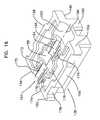
- FIG. 1Ais a perspective view of a terminal having features that are examples of aspects in accordance with the principles of the present disclosure.
- FIG. 1Bis a front view of the terminal of FIG. 1A .
- FIG. 1Cis a perspective view of a front side of a cover of the terminal of FIG. 1A .
- FIG. 2is a perspective view of a rear view of the cover of FIG. 1C .
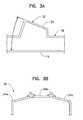
- FIG. 3Ais a cross-sectional view of an angled step of the cover taken on line 3 A- 3 A of FIG. 1B .
- FIG. 3Bis a cross-sectional view of an angled step of the cover taken on line 3 B- 3 B of FIG. 1B .
- FIG. 4is a perspective view of an adapter suitable for use in the terminal of FIG. 1A .
- FIG. 5is a perspective view of the terminal of FIG. 1A having an alternate embodiment of adapters.
- FIG. 7is a perspective view of a divider suitable for use with the anchor block of FIG. 6 .
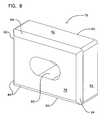
- FIG. 8is a perspective view of a cable seal suitable for use in the terminal of FIG. 1A having features that are examples of aspects in accordance with the principles of the present disclosure.
- FIG. 9is an exploded perspective view of the terminal of FIG. 1A .
- FIG. 10is a perspective view of a fiber routing tray suitable for use in the terminal of FIG. 1A having features that are examples of aspects in accordance with the principles of the present disclosure.
- FIG. 11is an expanded view of the fiber routing tray of FIG. 10 .
- FIG. 12is a cross-sectional view of the fiber routing tray taken on line 12 - 12 of FIG. 10 .
- FIG. 13is a schematic representation of a cable routing scheme for the terminal of FIG. 1A .
- FIG. 14is a fragmentary, perspective view of a retention device suitable for use in the terminal of FIG. 1A having features that are examples of aspects in accordance with the principles of the present disclosure.
- FIG. 16is a perspective view of a body of the retention device of FIG. 14 .
- FIG. 17is a perspective view of a cover piece for the retention device of FIG. 14 .
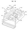
- FIG. 18is a perspective view of a fiber passage of the cover piece of FIG. 17 .
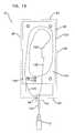
- FIG. 19is a fragmentary, perspective view of a boot suitable for use with the terminal of FIG. 1A .
- FIG. 20is a schematic representation of an installation scheme for the terminal of FIG. 1A .
- FIG. 21is a schematic representation of an installation scheme for the terminal of FIG. 1A .
- FIG. 22is a schematic representation of an installation scheme for the terminal of FIG. 1A .
- FIG. 24is an exploded, fragmentary, perspective view of the retention device of FIG. 23 .
- FIG. 25is a perspective view of a protective boot suitable for use with the retention device of FIG. 23 .
- FIG. 26is an exploded, perspective view of a fiber optic connection system suitable for use in the terminal of FIG. 1A .
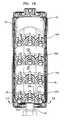
- the terminal 10for mounting to a fiber distribution cable 12 is shown.
- the terminal 10includes a housing, generally designated 14 , having a base, generally designated 16 , and a cover, generally designated 18 .
- the cover 18includes an outer surface 20 , an oppositely disposed rear surface 22 , a top wall 24 , an oppositely disposed bottom wall 26 , and sidewalls 28 .
- the terminal 10defines a footprint area that is defined by an outer perimeter 30 of the cover 18 .
- the footprint areais defined by the top wall 24 , the bottom wall 26 , and the sidewalls 28 .
- the footprint areais generally rectangular in shape. It will be understood, however, that the scope of the present disclosure is not limited to the cover having a footprint that is generally rectangular in shape.
- the footprint area of the terminal 10is less than 25 in 2 . In another embodiment, the footprint area of the terminal 10 is less than 21 in 2 .
- the outer surface 20 of the cover 18includes a plurality of angled steps, generally designated 32 .
- angled steps 32there are four angled steps 32 a , 32 b , 32 c , 32 d .
- the angled steps 32are configured on the outer surface 20 of the cover 18 in arcuate shaped rows. This arcuate row configuration efficiently utilizes space on the outer surface 20 of the cover 18 thereby allowing for a compact size of the terminal 10 .
- each angled step 32includes a plurality of mounting surfaces 34 on which are disposed adapters 36 .
- each angled step 32 a , 32 b , 32 c , 32 dincludes three mounting surfaces 34 a , 34 b , 34 c .
- Each mounting surface 34 a , 34 b , 34 cis disposed on the angled step 32 such that each mounting surface 34 a , 34 b , 34 c is oriented at an oblique angle ⁇ (shown in FIG. 3A ) to the base 16 and forms a mating angle ⁇ (shown in FIG.
- the mating angle ⁇is defined as the space between adjacent mounting surfaces 34 having a common edge with the adjacent mounting surfaces 34 diverging from each other.
- the mounting surface 34 a of the angled step 32 ashares a common edge 39 (shown only in FIG. 1B ) with the adjacent mounting surface 34 b .
- the mounting surface 34 aforms a mating angle ⁇ 1 with the mounting surface 34 b .
- the mating angle ⁇ 1which is measured on the outer surface 20 of the cover 18 , is an oblique angle.
- the mating angle ⁇ 1is less than about 210 degrees. In one embodiment, the mating angle ⁇ 1 is about 190 degrees.
- the mounting surface 34 cforms a mating angle ⁇ 2 with the mounting surface 34 b .
- the mating angle ⁇ 2is an oblique angle. In the subject embodiment, and by way of example only, the mating angle ⁇ 2 is less than about 210 degrees. In one embodiment, the mating angle ⁇ 2 is about 190 degrees. The angling of each of the mounting surfaces 34 with respect to the base 16 and to the adjacent mounting surfaces 34 further efficiently utilizes the space of the outer surface 20 of the cover 18 thereby allowing for a compact size of the terminal 10 .
- the adapters 36are oriented on each of the angled steps 32 such that one adapter 36 is disposed on each of the mounting surfaces 34 of each of the angled steps 32 .
- the adapters 36are oriented on the mounting surfaces 34 such that the adapters 36 are generally perpendicular to the corresponding mounting surfaces 34 .
- the adapters 36are oriented in an arcuate configuration on each of the angled steps 32 .
- the adapters 36include a first port 37 for receiving a connectorized end of a first cable having a first fiber optic connector 332 and a second port 38 for receiving a connectorized end of a second cable having a second fiber optic connector.
- the first cableis optically coupled to the second cable when the connectorized ends of the first and second cables are positioned within their respective ports 37 , 38 of the adapter 36 .
- the adapters 36 of the subject embodimenthave been described in U.S. patent application Ser. No. 11/657,404 (now U.S. Pat. No. 7,591,595), which was filed on Jan. 24, 2007 and which is hereby incorporated by reference.
- adapters 36 shown as the adapters 36can be any of a variety of adapters 36 including, but not limited to SC, angled SC, dual SC (shown only in FIG. 5 ), LC, dual LC, etc.
- the first connector 332 and the adapter 36are hardened or ruggedized. By hardened or ruggedized, it is meant that first connector 332 and the adapter 36 are adapted for outside environmental use.
- the first connector 332 and the adapter 36can include environmental seals for preventing moisture/water intrusion.
- the first connector 332includes a connector housing 339 including a main body 336 and a cover 341 .
- the connector housing 339extends from a distal end to a proximal end (distal and proximal are defined with respect to the connection with the first fiber optic cable for connector 332 ).
- a ferrule assembly 343mounts adjacent the distal end of the connector housing 339 and a strain relief boot 342 mounts adjacent the proximal end of the connector housing 339 .
- a sealing member 349(e.g., an o-ring seal) mounts around a periphery/exterior of the connector housing 339 .
- the sealing member 349is adapted for providing a seal between the connector housing 339 and the adapter 36 when the first connector 332 is plugged into the first port 37 of the adapter 36 .
- the first connector 332also includes a crimp band 338 that mounts over the main body 336 and the cover 341 , and a sealing tube 306 that seals the interface between the first cable and the connector housing 339 .
- the crimp band 338assists in retaining the cover 341 on the main body 336 and also assists in securing strength members 324 of the first cable in place between the cover 341 and the main body 336 .
- the first connector 332also includes first and second fastening structures for retaining (i.e., connecting, securing, etc.) the first connector 332 within the first port 37 of the adapter 36 .
- the first connector 332can include a latch 350 for mechanically interlocking with the adapter 36 when the first connector 332 is inserted in the first port 37 .
- the first connector 332also includes a coupling nut 340 adapted to thread into the adapter 36 to retain the first connector 332 within the first port 37 of the adapter 36 .
- the coupling nut 40 of the first connector 32is adapted to provide a second connection mechanism for securing the first connector 32 to the adapter 34 .
- the coupling nut 40can be threaded into corresponding threads provided within the first port 35 so as to provide a second connection with the adapter 34 .
- the coupling nut 40provides a connection with the adapter 34 that has a substantially greater pull-out resistance from the pull-out resistance provided by the latch 50 .
- the coupling nut 40retains the first connector 32 in the first port 35 even if a pull-out force of at least 100 pounds is applied to the first connector 32 .
- the coupling nut 340 of the first connector 332includes a first region and a second region.
- the first regionincludes a plurality of grooves to facilitate grasping of the first region, such as by a field technician or other user during connection or disconnection of the connector 332 with the adapter 36 .
- the groovesare for example a plurality of longitudinally oriented grooves that enable a user to more easily rotate the coupling nut 340 .
- Turning of the coupling nut 340enables a connection means of the second region to engage or disengage with the adapter 36 .
- the second regionincludes a connection means of exterior screw threads adapted to mate with internal threads provided within the first port 37 of the adapter 36 . In another embodiment, other connection means may also be used.
- the exterior of the connector housing 339includes a circumferential groove for mounting the sealing member 349 .
- the exterior of the housing 339also includes circumferential shoulders, against which the crimp band 338 can abut after assembly of the connector, and a circumferential shoulder.
- the crimp band 338is slid over a part of the connector housing 339 and crimped in place to hold the cover 341 securely onto the body 336 .
- the sealing tube 306is then slid over a portion of the crimp band 338 so as to cover the end of the first cable, the proximal end of the connector housing 339 and at least a portion of the crimp band 338 .
- Heatis then applied to the sealing tube 306 to cause the sealing tube 306 to shrink and tightly form around the adjacent portions of the connector housing 339 , the crimp band 338 , and the first cable, to seal connector from foreign substances.
- the sealing member 349is then mounted with the groove about the connector housing 339 to complete the installation of connector 332 onto the first cable.
- the boot 342retains the coupling nut 340 on the connector housing 339 .
- the adapter 36 of the fiber optic connection systemincludes an outer housing 344 having a first housing piece 345 that interconnects with a second housing piece 347 .
- the first housing piece 345defines a first end of the outer housing 344 at which the first port 37 is located.
- the second housing piece 347defines a second end of the outer housing 344 at which the second port 38 is located.
- An adapter assemblymounts within the outer housing 344 .
- the adapter 36also includes a mounting ring or nut 346 that mounts around the exterior of the outer housing 344 .
- the first housing piece 345 of the adapter 36includes a first region separated from a second region by a shoulder.
- the first and second regionshave generally cylindrical outer shapes and the shoulder provides a diameter reduction from the first region to the second region.
- the second regiondefines external threads located adjacent the shoulder. The external threads are sized to mate with corresponding internal threads 368 of the mounting nut 346 such that the mounting nut 346 can be threaded on the second region of the first housing piece 345 .
- the second regionalso includes a pair of oppositely positioned latches for use in securing the first housing piece 345 to the second housing piece 347 .
- the first regiondefines the first port 37 of the adapter 36 .
- Internal threadsare provided within the first region adjacent the first end of the housing 344 .
- the internal threads within the first port 37are sized to threadingly receive the exterior screw threads of the coupling nut 340 when the coupling nut is threaded into the first port 37 to provide a secure connection between the first connector 332 and the adapter 36 .
- the first housing piece 345defines an annular sealing surface positioned inside the first housing piece 345 at a location adjacent to the internal threads. An angled diameter transition decreases the internal diameter of the first port 37 from the internal threads to the annular sealing surface.
- the annular sealing surfaceis preferably generally cylindrical and is adapted to engage the sealing member 349 of the first connector 332 when the first connector 332 is fully inserted within the first port 37 . The interface between the annular sealing surface and the sealing member 349 provides an internal environmental seal between the first connector 332 and the adapter 36 .
- the fiber optic connection systempreferably has a compact configuration adapted to provide relatively high circuit densities.
- the diameter D 1 of the sealing member 349 and the diameter D 2 of the annular sealing surfaceeach are less than or equal to 15 mm. In an alternate embodiment, the diameter D 1 of the sealing member 349 and the diameter D 2 of the annular sealing surface each are less than or equal to 12.5 mm. In another embodiment, the diameter D 1 of the sealing member 349 and the diameter D 2 of the annular sealing surface each are less than or equal to 10 mm.
- adapter densityis defined as the number of adapters 36 per footprint area of the terminal 10 .
- the adapter densitycan be simplified to the number of adapters per square inch.
- a terminal 10 having a high adapter densityis desired as this provides a more efficient utilization of space than a terminal 10 having a lower adapter density.
- adapter densityis greater than or equal to about 12 adapters per 25 in 2 , or 0.48 adapters/in 2 .
- the adapter densityis greater than or equal to about 12 adapters per 21 in 2 , or 0.57 adapters/in 2 . In the embodiment shown in FIG.
- the adapter densityis greater than or equal to about 24 adapters per 25 in 2 , or 0.96 adapters/in 2 .
- the adapter densityis greater than or equal to about 1.14 adapters/in 2 .
- the bottom wall 26 of the cover 18includes a tail piece 44 that extends outwardly from the bottom wall 26 .
- the tail piece 44extends outwardly in a direction that is generally perpendicular to the bottom wall 26 .
- the tail piece 44defines a longitudinal axis 46 (shown as a dashed line in FIG. 2 ).
- the tail piece 44further defines a cable opening 48 that extends through the tail piece 44 along the longitudinal axis 46 such that the cable opening 48 is in communication with the interior cavity 40 .
- the anchor block 50includes a main body 52 that extends from a first end 54 to a second end 56 of the anchor block 50 .
- the main body 52is elongated along a center axis 58 (shown as a dashed line in FIG. 6 ) of the anchor block 50 .
- the main body 52 of the anchor block 50is configured to mechanically interlock with the cover 18 of the terminal 10 .
- the main body 52includes first and second interlocking tabs 60 , 62 that project outwardly from the main body 52 in opposite directions relative to the center axis 58 .
- the first and second interlocking tabs 60 , 62are configured to be received within corresponding first and second interlock receptacles provided within the interior cavity 40 of the cover 18 adjacent to the bottom end 26 .
- interference between the first and second interlocking tabs 60 , 62 and the structure forming the corresponding first and second interlock receptaclesresists movement of the anchor block 50 in a direction along the center axis 58 .
- the first end 54 of the anchor block 50is disposed in the interior cavity 40 of the cover 18 while the second end 56 of the anchor block 50 is disposed in the cable opening 48 of the tail piece 44 .
- the length of the anchor block 50 disposed in the cable opening 48 of the tail piece 44is greater than 25%.
- the length of the anchor block 50 disposed in the cable opening 48 of the tail piece 44is greater than 50%.
- the length of the anchor block disposed in the cable opening 48 of the tail piece 44is in the range of 25% to 50%.
- the anchor block 50also includes structure for securing the fiber distribution cable 12 to the main body 52 .
- the second end 56includes a central groove 64 for receiving a central buffer tube of the fiber distribution cable 12 .
- the second end 56also includes two side grooves 66 that are generally parallel to the central groove 64 and positioned on opposite sides of the central groove 64 .
- the side grooves 66are sized to receive strength members of the fiber distribution cable 12 .
- the anchor block 50also includes a fan-out portion, generally designated 68 , that fans-out/spreads-apart optical fibers of the fiber distribution cable 12 that are routed and managed within the interior cavity 40 of the cover 18 .
- the anchor block 50includes a fan-out channel 70 that extends from the central groove 64 to the first end 54 of the main body 52 of the anchor block 50 .
- the fan-out channel 70has a width W 1 that gradually widens as the fan-out channel 70 extends along the center axis 58 from the central groove 64 to the first end 54 of the anchor block 50 .
- a divider 72(see FIG. 7 ) is located within the fan-out channel 70 at the first end 54 of the anchor block 50 .
- the divider 72includes a plurality of openings 74 that individually receive the optical fibers to maintain separation of the optical fibers.
- the optical fibersextend from the end of the central buffer tube through the fan-out channel 70 to the divider 72 .
- the optical fiberseach extend through one of the openings 74 of the divider 72 .
- the tapered configuration of the fan-out channel 70allows the optical fibers to spread apart as the optical fibers extend from the end of the central buffer tube at the central groove 64 to the divider 72 .
- a securing materiale.g., an adhesive such as epoxy
- a cable sealfor sealing the fiber distribution cable 12 in the tail piece 44 of the cover 18 is shown.
- the cable seal 76is made of an elastic material such as rubber.
- the cable seal 76includes a first surface 78 , an oppositely disposed second surface 80 and a plurality of side surfaces 82 .
- the cable seal 76further includes a plurality of chamfers 84 that are located between the first surface 78 and each of the side surfaces 82 .
- the cable seal 76defines a cable entry hole 86 that extends through the cable seal 76 .
- the cable entry hole 86extends through the cable seal 76 in a direction that is generally perpendicular to the first surface 78 .
- the cable entry hole 86is sized to receive and sealing engage the fiber distribution cable 12 .
- the cable entry hole 86is generally shaped as an elongated circle in order to conform to the fiber distribution cable 12 . It will be understood, however, that the scope of the present disclosure is not limited to the cable entry hole 86 being shaped as an elongated circle.
- the cable seal 76is configured to be inserted into the cable opening 48 of the tail piece 44 .
- the cable seal 76is inserted into the cable opening 48 such that the first surface 78 faces the interior cavity 40 of the cover.
- the chamfers 84which are disposed between the first surface 78 and each of the side surfaces 82 , ease the insertion of the cable seal 76 in the cable opening 48 .
- the side surfaces 82 of the cable seal 76are in sealing engagement with the tail piece 44 .
- the cable seal 76provides sealing engagement between the cable opening 48 of the tail piece 44 and the fiber distribution cable 12 .
- the terminal 10includes the base 16 and the cover 18 .
- the base 16is adapted for snap-fit engagement with the cover 18 through a latch 88 , which is disposed on each longitudinal side 90 of the base, having a plurality of openings 92 adapted for engagement with a plurality of protrusions 94 disposed on each of the sidewalls 28 of the cover 18 .
- the terminal 10further includes a fiber routing tray, generally designated 96 .
- the fiber routing tray 96includes a top panel 98 , a bottom panel 100 , and first and second side panels 102 a , 102 b disposed about the periphery of the top and bottom panels 98 , 100 (directional references such as top and bottom are made with regard to FIG. 10 ).
- the top panel 98is disposed above the bottom panel 100 such that the top and bottom panels 98 , 100 define a storage space 104 (best shown in FIG. 12 ) between the top and bottom panels 98 , 100 .
- the first side panel 102 ais in connected engagement with both of the top and bottom panels 98 , 100 while the second side panel 102 b is in connected engagement with the bottom panel 100 .
- each of the first and second side panels 102 a , 102 bextend between the top and bottom panels 98 , 100 in a direction that is generally perpendicular to the top and bottom panels 98 , 100 . It will be understood, however, that the scope of the present disclosure is not limited to the first and second side panels 102 a , 102 b extending between the top and bottom panels 98 , 100 in a direction that is generally perpendicular.
- the bottom panel 100includes a plurality mounting holes 106 .
- the mounting holes 106are sized to receive mounting pins 108 (shown in FIG. 9 ) disposed in the interior cavity 40 of the cover 18 .
- the engagement of the mounting holes 106 and the mounting pins 108provide for proper alignment and retention of the fiber routing tray 96 in the interior cavity 40 of the cover 18 .
- the top panel 98also includes a plurality of holes 113 adapted to receive the mounting pins 108 disposed in the interior cavity 40 of the cover 18 .
- the bottom panel 100further includes a ramp portion 114 disposed at the bottom end portion 112 of the bottom panel 100 .
- the ramp portion 114is disposed at an angle ⁇ with respect to the bottom end portion 112 of the bottom panel 100 .
- the ramp portion 114is disposed at an angle that is less than or equal to 45 degrees from the bottom end portion 112 of the bottom panel 100 .
- the ramp portion 114provides a location for optical fibers 124 disposed in the interior cavity 40 of the cover 18 and engaged with the adapters 36 to enter the storage space 104 of the fiber routing tray 96 .
- the fiber routing tray 96is a continuous piece of material.
- the second side panel 102 bis bent at a first fold 116 , which is disposed between the bottom panel 100 and the second side panel 102 b , such that the second side panel 102 b is generally perpendicular to the bottom panel 100 .
- the first side panel 102 ais bent at a second fold 118 disposed between the bottom panel 100 and the first side panel 102 a such that the first side panel 102 a is generally perpendicular to the bottom panel 100 .
- the top panel 98is bent at a third fold 120 disposed between the top panel 98 and the first side panel 102 a such that the top panel 98 is generally perpendicular to the first side panel 102 a .
- the ramp portion 114is bent at a forth fold 122 disposed between the ramp portion 114 and the bottom end portion 112 of the bottom panel 100 such that the ramp portion 114 is disposed at an angle ⁇ with respect to the bottom end portion 112 of the bottom panel 100 .
- optical fibers 124 that are engaged with the adapters 36are routed into the storage space 104 of the fiber routing tray 96 through the ramp portion 114 of the bottom panel 100 .
- the optical fibers 124are bend insensitive fibers.
- An exemplary bend insensitive fiberis BendBright XS produced by Draka Comteq. It will be understood, however, that the scope of the present disclosure is not limited to BendBright XS fiber as various bend insensitive fibers could be used.
- Exemplary disclosures of bend insensitive fibersinclude U.S. Pat. Nos. 4,838,643 and 5,278,931, both of which are hereby incorporated by reference.
- bend radius protectorsmay be installed to prevent attenuation of the optical fibers 124 .
- the optical fibers 124are routed from the ramp portion 114 of the bottom panel 100 through a passage 126 defined between one of the mounting pins 108 and the adjacent sidewall 28 (shown as a dashed line in FIG. 13 ) of the cover 18 .
- the optical fibers 124are then loosely coiled in the storage space 104 such that the coils of optical fibers 124 are interiorly disposed with respect to the mounting pins 108 .
- the optical fibers 124are in connected engagement with a fan-out device 128 that combines the individual optical fibers 124 into a multi-fiber optic cable 130 .
- the multi-fiber optic cable 130then exits the storage space 104 of the fiber routing tray 96 and the interior cavity 40 of the cover 18 through the cable opening 48 of the tail piece 44 .
- a multi-fiber splice 132connects the multi-fiber optic cable 130 to the fiber distribution cable 12 .
- the multi-fiber optic cable 130can be pulled from the storage space 104 of the fiber routing tray 96 through the cable opening 48 of the tail piece 44 of the cover 18 .
- the loosely coiled arrangement of optical fibers 124 in the storage space 104 of the fiber routing tray 96allows for the multi-fiber optic cable 130 to be pulled from the storage space 104 without having to disassemble the housing 14 . This is advantageous as it does not disrupt or create any potential disruption of the connections between the pre-assembled optical fibers 124 and the adapters 36 .
- the multi-fiber optic cable 130can be pulled from the terminal 10 , the multi-fiber optic cable 130 is protected from being pulled too far out of the tail piece 44 by the routing of the optical fibers 124 through the passage 126 , which is disposed between one of the mounting pins 108 and the adjacent sidewall 28 of the cover 18 .
- the optical fibers 124will rap around the mounting pin 108 thereby providing resistance which will notify the installer that the storage limit has been reached.
- a retention devicefor securing the fiber distribution cable 12 to the terminal 10 after splicing the fiber distribution cable 12 to the multi-fiber optic cable 130 will be described.
- the retention device 134is connectedly engaged with the tailpiece 44 of the cover 18 of the housing 14 such that the retention device 134 extends outwardly from the tail piece 44 .
- the retention device 134extends outwardly from the tail piece 44 in a direction that is generally perpendicular to the bottom wall 26 of the cover 18 .
- the retention device 134includes a base piece, generally designated 136 , a body, generally designated 138 , and a cover piece, generally designated 140 .
- the base piece 136is an integral part of the tail piece 44 of the cover 18 . It will be understood, however, that the scope of the present disclosure is not limited to the base piece 136 being integral with the tail piece 44 .
- the base piece 136includes longitudinal sidewalls 142 with each longitudinal sidewall 142 having a catch 144 .
- the base piece 136defines longitudinal slots 146 . In the subject embodiment, and by way of example only, there are two longitudinal slots 146 .
- the longitudinal slots 146are oriented in the base piece 136 so as to be generally parallel to the center axis 58 of the tail piece 44 . It will be understood, however, that the scope of the present disclosure is not limited to the longitudinal slots 146 being generally parallel to the center axis 58 of the tail piece 44 .
- the body 138 of the retention device 134includes a lower surface 148 , an oppositely disposed upper surface 150 , a front side 152 , a back side 154 , and longitudinal sides 156 (directional references such as upper, lower, front and back are relative to FIG. 16 ).
- the body 138further includes a central axis 158 that is centrally disposed in the body 138 .
- the lower surface 148includes longitudinal protrusions 160 that extend downwardly from the lower surface 148 in a direction that is generally perpendicular to the lower surface 148 .
- the longitudinal protrusions 152are configured to be received in the longitudinal slots 146 of the base piece 136 in order to aid in the retention of the body 138 in the base piece 136 .
- the upper surface 150defines a fiber passage, generally designated 161 .
- the fiber passage 161includes a cable jacket cavity 162 disposed near the front side 152 of the body 138 .
- the cable jacket cavity 162is adapted to receive the cable jacket of the fiber distribution cable 12 .
- the cable jacket cavity 162includes a plurality of grasping protrusions that extend outwardly from the cable jacket cavity 162 . The grasping protrusions aid in the retention of the fiber distribution cable 12 in the retention device 134 .
- the fiber passage 161further includes a first center groove 164 disposed adjacent to the cable jacket cavity 162 .
- the first center groove 164is aligned with the central axis 158 of the body 138 .
- the first center groove 164is adapted to receive a buffer tube of the fiber distribution cable 12 .
- Disposed on either side of the first center groove 164are side grooves 166 .
- the side grooves 166are generally parallel to the first center groove 164 .
- the side grooves 166are adapted to receive strength members of the fiber distribution cable 12 .
- the fiber passage 161 defined by the upper surface 150 of the body 138further includes a recess 168 disposed adjacent to the first center groove 164 and the side grooves 166 .
- the recess 168is the dividing line between the fiber distribution cable 12 and the multi-fiber optic cable 130 .
- the recess 168is adapted to receive the multi-fiber splice 132 that optically couples the optical fibers of the fiber distribution cable 12 and the multi-fiber optic cable 130 and a crimp that couples and retains the strength members of the fiber distribution cable 12 to strength members in the multi-fiber optic cable 130 .
- the fiber passage 161also includes a second center groove 170 that extends from the recess 168 through the back side 154 of the body 138 .
- the second center groove 170is aligned with the central axis 158 of the body 138 .
- the second center groove 170is adapted to receive a buffer tube of the multi-fiber optic cable 130 .
- Disposed on either side of the second center groove 170are grooves 172 .
- the grooves 172are generally parallel to the second center groove 170 .
- the grooves 172are adapted to receive strength members of the multi-fiber optic cable 130 .
- a plurality of adhesive recesses 174is defined by the upper surface 150 of the body 138 .
- the adhesive recesses 174provide a receptacle for adhesive (such as epoxy, etc.).
- the adhesivecan be used to secure the fiber distribution cable 12 and the multi-fiber optic cable 130 in the retention device 134 .
- the type of adhesive used in the adhesive recesses 174will affect the force required to remove the fiber distribution cable 12 and the multi-fiber optic cable 130 by pulling on the cables (pull-out force).
- Each adhesive recess 174defines a plurality of adhesive passages 176 that provide communication between the adhesive recess 174 and the fiber passage 161 .
- the adhesive passages 176allow for adhesive that is poured into the adhesive recesses 174 to flow into the fiber passage 161 .
- each of the longitudinal sides 156 of the body 138defines a latch groove 178 .
- the retention portion 192 of the retention protrusion 188extends outwardly from the body portion 190 and defines a retention groove 194 .
- the retention groove 194extends along the length of the retention portion 192 such that the retention groove 194 is generally transverse to a central longitudinal axis 196 defined by the cover piece 140 .
- the retention protrusion 188is hook-shaped. This configuration allows the retention protrusion 188 to receive a lip 198 (shown on FIG. 15 ) disposed around the tail piece 44 of the cover 18 for laterally retaining the retention device 134 to the cover 18 .
- the cavities and recesses defined on the bottom surface 182 of the cover piece 140are oriented on the bottom surface 182 so that the cavities and recesses are aligned with the cavities and recesses defined on the upper surface 150 of the body 138 when the body 138 and the cover 140 are engaged.
- the body 138 of the retention device 134is inserted into the base piece 136 such that the longitudinal slots 146 receive the longitudinal protrusions 160 .
- the multi-fiber splice 132which connects the fiber distribution cable 12 and the multi-fiber optic cable 130 , is inserted into the recess 168 of the body 138 of the retention device 134 .
- the multi-fiber splice 132is inserted into the recess 168 such that the cable jacket, the buffer tube, and strength members of the fiber distribution cable 12 are inserted into the cable jacket cavity 162 , the first center groove 164 and the side grooves 166 , respectively, and the buffer tube and the strength members of the multi-fiber optic cable 130 are inserted into the second center groove 164 and the grooves 172 , respectively.
- the cover piece 140With the multi-fiber splice 132 properly inserted into the body 138 , the cover piece 140 is engaged with the base piece 136 such that the fiber distribution cable 12 and the multi-fiber optic cable 130 are disposed in the fiber passage 200 of the bottom surface 182 of the cover piece 140 .
- the cover piece 140is then pressed toward the base piece 136 such that the resilient latches 214 of the cover piece 140 engage the catches 144 of the base piece 136 .
- Epoxycan be added to the body 138 and/or the cover piece 140 prior to the engagement of the cover piece with the base piece 136 in order to secure the fiber distribution cable 12 in the retention device 134 .
- a boot 228is molded over the retention device 134 and the tail piece 44 of the cover 18 following the installation of the fiber distribution cable 12 and the multi-fiber optic cable 130 in the retention device 134 .
- the boot 228includes a plurality of strain relief grooves 230 disposed near a cable end 232 of the boot 228 .
- the multi-fiber optic cable 130is pulled from the interior cavity 40 through the tail end 44 of the housing 14 .
- the multi-fiber optic cable 130is then spliced to the fiber distribution cable 12 with a multi-fiber splice 132 .
- the boot 228is molded over the retention device 134 to prevent dust, rain, snow, or ice from entering the terminal 10 .
- the boot 228is molded over a portion of the tail end 44 of the cover 18 , the retention device 134 and an end portion of the fiber distribution cable 12 .
- the retention device 400includes the base piece 136 , a body 402 , and a cover piece 404 .
- the body 402 and the cover piece 404are similar to the body 138 and the cover piece 140 described with regard to the retention device 134 .
- each of the body 402 and the cover piece 404include a grounding opening 405 (shown in FIG. 24 ) that is adapted to receive a grounding lug assembly, generally designated 406 .
- the grounding opening 405is defined near fiber distribution cable ends 407 (shown in FIG. 24 ) of the body 402 and the cover piece 404 .
- the grounding opening 405extends through a cable jacket recess 409 defined at the fiber distribution cable ends 407 of the body 402 and the cover piece 404 .
- a plurality of embodiments of the grounding lug assembly 406has been provided in U.S. patent application Ser. No. 11/157,561 (now U.S. Pat. No. 7,492,996), which was filed on Jun. 21, 2005 and is hereby incorporated by reference.
- the grounding lug assembly 406includes a lug 408 , a compression insert 410 , and a nut 412 .
- the lug 408includes a first axial end portion 414 and a second axial end portion 416 .
- the first axial end portion 414is bifurcated with external threads 418 , which are adapted to engage with the nut 412 , disposed on an outer surface of the first axial end portion 414 .
- the first axial end portion 414defines a cable slot 420 which is adapted to receive cable sheathing 422 that covers the fiber distribution cable 12 .
- cable sheathing 422(or cable armor) is a sheathing that is made of steel or aluminum.
- the second axial end portion 416 of the lug 408includes a plurality of threads 423 disposed on an outer surface of the second axial end portion 416 .
- the plurality of threads 423is adapted to threadedly engage internal threads disposed on a grounding nut 424 .
- the second axial end portion 416is adapted to engage a grounding wire (such as a #6 wire).
- the compression insert 410includes an upper portion 425 having curved end surfaces 426 .
- the upper portion 425fits within the nut 412 and has a slightly smaller diameter than the curvature of the external threads 418 on the first axial end portion 414 so as not to interfere with advancement of the nut 412 along the external threads 418 .
- the compression insert 410further includes a lower portion 428 having a nut engaging surface 430 and a cable engaging surface 432 .
- the nut engaging surface 430includes a plurality of nut engaging tabs 434 that are configured for engaging the nut 412 as it advances along the external threads 418 of the first axial end portion 414 .
- the cable engaging surface 432defines a cable recess 436 having a pair of shoulders 438 disposed along the cable recess 436 .
- the cable recess 4is adapted for receiving the cable sheathing 422 of the fiber distribution cable 12 .
- the shoulders 438are adapted to engage corresponding shoulders 440 disposed in the cable slot 420 . The engagement of the shoulders 438 and the corresponding shoulders 440 prevents over compression of the fiber distribution cable 12 , which might lead to damage of the optical fibers within the fiber distribution cable 12 .
- the protective boot 442is molded over the retention device 400 , a portion of the tail piece 44 of the cover 18 , and a portion of the grounding lug assembly 406 following the installation of the fiber distribution cable 12 and the multi-fiber optic cable 130 in the retention device 400 .
- the protective boot 442includes a plurality of strain relief grooves 444 disposed near a cable end 446 of the protective boot 442 .
- the second axial end portion 416 and the grounding nut 425are not over molded by the protective boot 442 . This exposure of the second axial end portion 416 and the grounding nut 425 allows the cable sheathing 422 to be grounded by a grounding wire.
Landscapes
- Physics & Mathematics (AREA)
- General Physics & Mathematics (AREA)
- Optics & Photonics (AREA)
- Light Guides In General And Applications Therefor (AREA)
- Mechanical Coupling Of Light Guides (AREA)
Abstract
Description
Claims (10)
Priority Applications (1)
| Application Number | Priority Date | Filing Date | Title |
|---|---|---|---|
| US12/955,701US8213761B2 (en) | 2007-10-09 | 2010-11-29 | Mini drop terminal |
Applications Claiming Priority (3)
| Application Number | Priority Date | Filing Date | Title |
|---|---|---|---|
| US97863807P | 2007-10-09 | 2007-10-09 | |
| US12/248,564US7844158B2 (en) | 2007-10-09 | 2008-10-09 | Mini drop terminal |
| US12/955,701US8213761B2 (en) | 2007-10-09 | 2010-11-29 | Mini drop terminal |
Related Parent Applications (1)
| Application Number | Title | Priority Date | Filing Date |
|---|---|---|---|
| US12/248,564DivisionUS7844158B2 (en) | 2007-10-09 | 2008-10-09 | Mini drop terminal |
Publications (2)
| Publication Number | Publication Date |
|---|---|
| US20110067452A1 US20110067452A1 (en) | 2011-03-24 |
| US8213761B2true US8213761B2 (en) | 2012-07-03 |
Family
ID=40521963
Family Applications (2)
| Application Number | Title | Priority Date | Filing Date |
|---|---|---|---|
| US12/248,564ActiveUS7844158B2 (en) | 2007-10-09 | 2008-10-09 | Mini drop terminal |
| US12/955,701ActiveUS8213761B2 (en) | 2007-10-09 | 2010-11-29 | Mini drop terminal |
Family Applications Before (1)
| Application Number | Title | Priority Date | Filing Date |
|---|---|---|---|
| US12/248,564ActiveUS7844158B2 (en) | 2007-10-09 | 2008-10-09 | Mini drop terminal |
Country Status (7)
| Country | Link |
|---|---|
| US (2) | US7844158B2 (en) |
| EP (2) | EP2198328B1 (en) |
| AU (1) | AU2008310798B2 (en) |
| BR (1) | BRPI0817857B1 (en) |
| ES (1) | ES2700434T3 (en) |
| MX (1) | MX2010003804A (en) |
| WO (1) | WO2009049037A2 (en) |
Cited By (31)
| Publication number | Priority date | Publication date | Assignee | Title |
|---|---|---|---|---|
| US20150168663A1 (en)* | 2012-04-03 | 2015-06-18 | Tyco Electronics Raychem Bvba | Telecommunications enclosure organizer |
| US20150253528A1 (en)* | 2012-10-02 | 2015-09-10 | 3M Innovative Properties Company | Optical fibre distribution enclosure |
| US20170045701A1 (en)* | 2014-04-14 | 2017-02-16 | Tyco Electronics Raychem Bvba | Fiber optic enclosure with cable management drawer |
| US20180164523A1 (en)* | 2016-12-09 | 2018-06-14 | Furukawa Electric Latam S.A. | Optical termination box |
| US10007080B2 (en) | 2016-08-31 | 2018-06-26 | Corning Research & Development Corporation | Flex port enabled telecommunications closure |
| US10359577B2 (en) | 2017-06-28 | 2019-07-23 | Corning Research & Development Corporation | Multiports and optical connectors with rotationally discrete locking and keying features |
| US10379298B2 (en) | 2017-06-28 | 2019-08-13 | Corning Research & Development Corporation | Fiber optic connectors and multiport assemblies including retention features |
| US10641967B1 (en) | 2018-11-16 | 2020-05-05 | Corning Research & Development Corporation | Multiport assemblies including a modular adapter support array |
| US20200233170A1 (en)* | 2017-10-17 | 2020-07-23 | Corning Research & Development Corporation | Enclosure for splicing of optical fibers |
| US10768382B2 (en) | 2018-11-29 | 2020-09-08 | Corning Research & Development Corporation | Multiport assemblies including access apertures and a release tool |
| US11073670B2 (en) | 2016-08-12 | 2021-07-27 | Corning Optical Communications LLC | Device and method for sealing multiport splitters |
| US11187859B2 (en) | 2017-06-28 | 2021-11-30 | Corning Research & Development Corporation | Fiber optic connectors and methods of making the same |
| US11294133B2 (en) | 2019-07-31 | 2022-04-05 | Corning Research & Development Corporation | Fiber optic networks using multiports and cable assemblies with cable-to-connector orientation |
| US11300746B2 (en) | 2017-06-28 | 2022-04-12 | Corning Research & Development Corporation | Fiber optic port module inserts, assemblies and methods of making the same |
| US20220317405A1 (en)* | 2021-03-31 | 2022-10-06 | Sterlite Technologies Limited | Optical fibre enclosure with staggered ports |
| US11487073B2 (en) | 2019-09-30 | 2022-11-01 | Corning Research & Development Corporation | Cable input devices having an integrated locking feature and assemblies using the cable input devices |
| US11536921B2 (en) | 2020-02-11 | 2022-12-27 | Corning Research & Development Corporation | Fiber optic terminals having one or more loopback assemblies |
| US11604320B2 (en) | 2020-09-30 | 2023-03-14 | Corning Research & Development Corporation | Connector assemblies for telecommunication enclosures |
| US11650388B2 (en) | 2019-11-14 | 2023-05-16 | Corning Research & Development Corporation | Fiber optic networks having a self-supporting optical terminal and methods of installing the optical terminal |
| US11668890B2 (en) | 2017-06-28 | 2023-06-06 | Corning Research & Development Corporation | Multiports and other devices having optical connection ports with securing features and methods of making the same |
| US11686913B2 (en) | 2020-11-30 | 2023-06-27 | Corning Research & Development Corporation | Fiber optic cable assemblies and connector assemblies having a crimp ring and crimp body and methods of fabricating the same |
| US11880076B2 (en) | 2020-11-30 | 2024-01-23 | Corning Research & Development Corporation | Fiber optic adapter assemblies including a conversion housing and a release housing |
| US11886010B2 (en) | 2019-10-07 | 2024-01-30 | Corning Research & Development Corporation | Fiber optic terminals and fiber optic networks having variable ratio couplers |
| US11927810B2 (en) | 2020-11-30 | 2024-03-12 | Corning Research & Development Corporation | Fiber optic adapter assemblies including a conversion housing and a release member |
| US11947167B2 (en) | 2021-05-26 | 2024-04-02 | Corning Research & Development Corporation | Fiber optic terminals and tools and methods for adjusting a split ratio of a fiber optic terminal |
| US11994722B2 (en) | 2020-11-30 | 2024-05-28 | Corning Research & Development Corporation | Fiber optic adapter assemblies including an adapter housing and a locking housing |
| US12019279B2 (en) | 2019-05-31 | 2024-06-25 | Corning Research & Development Corporation | Multiports and other devices having optical connection ports with sliding actuators and methods of making the same |
| US12044894B2 (en) | 2018-12-28 | 2024-07-23 | Corning Research & Development Corporation | Multiport assemblies including mounting features or dust plugs |
| US12169317B2 (en)* | 2019-09-06 | 2024-12-17 | Opterna Am, Inc. | Multi-conformable modules for fiber optic cable distribution systems |
| US12271040B2 (en) | 2017-06-28 | 2025-04-08 | Corning Research & Development Corporation | Fiber optic extender ports, assemblies and methods of making the same |
| US12372727B2 (en) | 2020-10-30 | 2025-07-29 | Corning Research & Development Corporation | Female fiber optic connectors having a rocker latch arm and methods of making the same |
Families Citing this family (56)
| Publication number | Priority date | Publication date | Assignee | Title |
|---|---|---|---|---|
| US7903923B2 (en)* | 2007-10-09 | 2011-03-08 | Adc Telecommunications, Inc. | Drop terminal releasable engagement mechanism |
| CN102209921B (en) | 2008-10-09 | 2015-11-25 | 康宁光缆系统有限公司 | There is the fibre-optic terminus supported from the adapter panel of the input and output optical fiber of optical splitters |
| CN106130646B (en) | 2009-03-05 | 2019-04-30 | Adc电信公司 | Methods, systems and apparatus for integrating wireless technologies into fiber optic networks |
| US20110097052A1 (en)* | 2009-10-21 | 2011-04-28 | Solheid James J | Fiber Access Terminal Mounted at a Mid-Span Access Location of a Telecommunications Cable |
| US9078287B2 (en) | 2010-04-14 | 2015-07-07 | Adc Telecommunications, Inc. | Fiber to the antenna |
| US8837940B2 (en) | 2010-04-14 | 2014-09-16 | Adc Telecommunications, Inc. | Methods and systems for distributing fiber optic telecommunication services to local areas and for supporting distributed antenna systems |
| WO2012054454A2 (en) | 2010-10-19 | 2012-04-26 | Corning Cable Systems Llc | Transition box for multiple dwelling unit fiber optic distribution network |
| US9219546B2 (en) | 2011-12-12 | 2015-12-22 | Corning Optical Communications LLC | Extremely high frequency (EHF) distributed antenna systems, and related components and methods |
| US10110307B2 (en) | 2012-03-02 | 2018-10-23 | Corning Optical Communications LLC | Optical network units (ONUs) for high bandwidth connectivity, and related components and methods |
| US8842954B2 (en)* | 2012-05-02 | 2014-09-23 | Corning Cable Systems Llc | Cable assembly |
| US9004778B2 (en) | 2012-06-29 | 2015-04-14 | Corning Cable Systems Llc | Indexable optical fiber connectors and optical fiber connector arrays |
| US9049500B2 (en) | 2012-08-31 | 2015-06-02 | Corning Cable Systems Llc | Fiber optic terminals, systems, and methods for network service management |
| US8917968B2 (en)* | 2012-11-06 | 2014-12-23 | Corning Optical Communications LLC | Furcation plugs having segregated channels to guide epoxy into passageways for optical fiber furcation, and related assemblies and methods |
| EP2738584B1 (en)* | 2012-12-03 | 2021-07-21 | Corning Optical Communications LLC | Fiber optic distribution device |
| CA2896015A1 (en)* | 2012-12-21 | 2014-06-26 | Badr Elmaanaoui | Optical fiber protector |
| AU2014252282A1 (en) | 2013-04-07 | 2015-11-05 | Adc Telecommunications (Shanghai) Distribution Co., Ltd. | Fiber optic connection assembly |
| US9829668B2 (en)* | 2013-08-23 | 2017-11-28 | CommScope Connectivity Belgium BVBA | Pass-through assembly having an anchor member and a cover |
| CN105676380B (en) | 2014-11-21 | 2019-07-12 | 泰科电子(上海)有限公司 | Cable runs system and multifibre joint |
| AU2016206914B2 (en) | 2015-01-12 | 2018-04-05 | Afl Telecommunications Llc | Fiber optic terminal enclosure |
| CN111384691B (en) | 2015-03-16 | 2021-08-27 | 康普技术有限责任公司 | Housing for a cable distribution assembly |
| EP3822676A1 (en) | 2015-04-02 | 2021-05-19 | CommScope Technologies LLC | Fiber optic network architecture using high fiber-count fiber optic connectors |
| EP3311210B1 (en) | 2015-06-19 | 2022-10-12 | Commscope Technologies LLC | Optical termination enclosure |
| WO2017083519A1 (en) | 2015-11-11 | 2017-05-18 | Afl Telecommunications Llc | Optical connection terminals for fiber optic communications networks |
| WO2017120059A1 (en) | 2016-01-07 | 2017-07-13 | Commscope Technologies Llc | Flexible device for distributing hybrid cable and transitioning from trunk cable to jumper cable |
| AU2017217511A1 (en) | 2016-02-08 | 2018-07-05 | Commscope Technologies Llc | Cable slack storage system for terminal |
| USD876364S1 (en) | 2016-03-16 | 2020-02-25 | Commscope Technologies Llc | Cable breakout enclosure |
| USD825471S1 (en) | 2016-03-16 | 2018-08-14 | Commscope Technologies Llc | Cable breakout enclosure design |
| CN107317157B (en)* | 2016-04-25 | 2024-01-30 | 普罗斯通信技术(苏州)有限公司 | Integrated cable assembly |
| CN112180529B (en)* | 2016-05-23 | 2023-03-10 | 康普连通比利时私人有限公司 | Optical terminal package with reinforced self-supporting tether |
| US10164389B2 (en) | 2016-09-26 | 2018-12-25 | Commscope Technologies Llc | Breakout enclosure for transitioning from trunk cable to jumper cable |
| US10355423B2 (en) | 2016-10-24 | 2019-07-16 | Commscope Technologies Llc | Hybrid connector assembly with integrated overvoltage protection |
| USD831578S1 (en)* | 2016-10-28 | 2018-10-23 | Corning Optical Communications LLC | Fiber optic closure |
| US10816746B2 (en) | 2016-12-20 | 2020-10-27 | Multilink Inc. | Fiber tap optical cross connect terminal closure and terminal splice closure |
| WO2018175370A1 (en) | 2017-03-21 | 2018-09-27 | Commscope Technologies Llc | Modular breakout enclosure for transitioning from trunk cable to jumper cable |
| US9977211B1 (en) | 2017-04-21 | 2018-05-22 | Afl Telecommunications Llc | Optical connection terminals for fiber optic communications networks |
| WO2018222740A1 (en) | 2017-05-30 | 2018-12-06 | Commscope Technologies Llc | Reconfigurable optical networks |
| US10502915B2 (en) | 2017-06-29 | 2019-12-10 | Commscope Technologies Llc | Device for distributing trunk cable to jumper cable |
| BR112020000901A2 (en) | 2017-07-25 | 2020-07-21 | Commscope Technologies Llc | permanent fan-out arrangement |
| EP3673308B1 (en) | 2017-08-23 | 2024-04-03 | Commscope Technologies LLC | Drop terminal |
| US20210080670A1 (en)* | 2017-08-24 | 2021-03-18 | Commscope Technologies Llc | Fiber-optic connection assemblies, features, components, and methods |
| US10684426B2 (en) | 2017-09-08 | 2020-06-16 | Commscope Technologies Llc | Telecommunication enclosures |
| MX2020005413A (en) | 2017-11-28 | 2020-10-28 | Commscope Technologies Llc | Indicia and method for identifying telecommunications components. |
| TWM558369U (en) | 2018-01-02 | 2018-04-11 | 建毅科技股份有限公司 | Fiber distribution box |
| US10656360B2 (en)* | 2018-01-23 | 2020-05-19 | Panduit Corp. | Epoxy transitions for optical fiber modules |
| EP3776748A4 (en) | 2018-03-29 | 2022-01-26 | CommScope Technologies LLC | SIGNS AND METHODS OF IDENTIFICATION OF TELECOMMUNICATIONS COMPONENTS |
| WO2019195602A1 (en) | 2018-04-06 | 2019-10-10 | Commscope Technologies Llc | Flexible organizer and self-supporting unit |
| MX2021000254A (en) | 2018-07-09 | 2021-03-25 | Commscope Technologies Llc | TELECOMMUNICATIONS TERMINAL. |
| USD916044S1 (en) | 2018-10-19 | 2021-04-13 | Commscope Technologies Llc | Telecommunications enclosure |
| USD901391S1 (en)* | 2019-02-19 | 2020-11-10 | North American Interconnect L.L.C. | Distribution housing |
| USD935428S1 (en)* | 2019-04-19 | 2021-11-09 | Commscope Technologies Llc | Telecommunications identification plate |
| WO2021026486A1 (en) | 2019-08-08 | 2021-02-11 | Commscope Technologies Llc | Optical fiber management assembly |
| US11953750B2 (en) | 2020-04-30 | 2024-04-09 | Commscope Technologies Llc | Interlocking fiber optic connector holder |
| CN111799582B (en)* | 2020-05-19 | 2021-09-14 | 华为技术有限公司 | Binding post and transmission equipment |
| EP4063929A1 (en)* | 2021-01-18 | 2022-09-28 | Sterlite Technologies Limited | Enclosure with converging ports |
| US11585998B2 (en)* | 2021-03-31 | 2023-02-21 | Sterlite Technologies Limited | Optical fibre cable clamping apparatus |
| MX2023007277A (en)* | 2022-04-06 | 2023-10-24 | Fiberhome Telecommunication Tech Co Ltd | Optical fiber function box and optical fiber function box module. |
Citations (161)
| Publication number | Priority date | Publication date | Assignee | Title |
|---|---|---|---|---|
| US4453291A (en) | 1982-06-21 | 1984-06-12 | Harvey Hubbell Incorporated | Grip for pulling fiber optic cable |
| US4478486A (en) | 1982-08-12 | 1984-10-23 | Raychem Corporation | Fiber optic splice organizer |
| US4648168A (en) | 1983-12-19 | 1987-03-10 | N.V. Raychem S.A. | Optical fibre breakout |
| US4652072A (en) | 1986-04-28 | 1987-03-24 | Wire Tech Incorporated | Cable-connector assembly |
| US4684221A (en) | 1985-01-16 | 1987-08-04 | Olympus Optical Co., Ltd. | Graded refractive index single lens system |
| US4685764A (en) | 1985-02-01 | 1987-08-11 | Amp Incorporated | Splice organizer for optical cable splices |
| US4717231A (en) | 1983-01-05 | 1988-01-05 | Vincent Dewez | Interconnecting and distributing box for optical fibers |
| US4744622A (en) | 1986-09-12 | 1988-05-17 | Amp Incorporated | Optical fiber splice case |
| US4761052A (en) | 1986-01-31 | 1988-08-02 | N. V. Raychem S.A. | Optical fibre splice case |
| US4805979A (en) | 1987-09-04 | 1989-02-21 | Minnesota Mining And Manufacturing Company | Fiber optic cable splice closure |
| US4838643A (en) | 1988-03-23 | 1989-06-13 | Alcatel Na, Inc. | Single mode bend insensitive fiber for use in fiber optic guidance applications |
| US4908482A (en) | 1987-12-08 | 1990-03-13 | Raychem Corporation | Cable closure |
| US4913522A (en) | 1984-04-11 | 1990-04-03 | Nv Raychem Sa | Electrofit fibre optics butt splice |
| US4958903A (en) | 1988-12-09 | 1990-09-25 | At&T Bell Laboratories | Splice closure |
| US4986762A (en) | 1989-08-15 | 1991-01-22 | Minnesota Mining And Manufacturing Company | Termination module for use in an array of modules |
| US5029958A (en) | 1989-04-28 | 1991-07-09 | Scientific-Atlanta, Inc. | Optical fiber enclosure for optoelectronic converter |
| US5046811A (en) | 1989-07-17 | 1991-09-10 | Jung Roger E | Junction box for optical communications cords, and gland assembly for cord |
| US5048916A (en) | 1982-09-07 | 1991-09-17 | Amp Incorporated | Fiber optic connection system |
| US5076656A (en) | 1984-06-08 | 1991-12-31 | Briggs Robert C | High precision optical fiber connectors |
| US5097530A (en) | 1991-04-04 | 1992-03-17 | Raychem Corporation | Optical fiber enclosure including novel retaining ring |
| US5097529A (en) | 1991-03-22 | 1992-03-17 | At&T Bell Laboratories | Space-saving optical fiber cable closure |
| US5122069A (en) | 1989-07-28 | 1992-06-16 | Amp Incorporated | Access flooring module |
| US5129030A (en) | 1991-05-30 | 1992-07-07 | At&T Bell Laboratories | Movable lightguide connector panel |
| US5133039A (en) | 1990-10-29 | 1992-07-21 | At&T Bell Laboratories | Aerial fiber optic cable case |
| US5133038A (en) | 1980-04-17 | 1992-07-21 | Reliance Comm/Tec. Corporation | Fiber optic splice case |
| EP0511147A1 (en) | 1991-04-22 | 1992-10-28 | Telefonica De Espana, S.A. | Universal access optical fiber junction box |
| US5185845A (en) | 1990-12-13 | 1993-02-09 | At&T Bell Laboratories | Optical fiber closure having enhanced storage capability |
| US5208893A (en) | 1992-05-21 | 1993-05-04 | Raynet Corporation | Optical fiber splice tray and splice holder |
| US5212761A (en) | 1992-04-27 | 1993-05-18 | At&T Bell Laboratories | Fiber optic module |
| US5214735A (en) | 1992-04-06 | 1993-05-25 | Adc Telecommunications, Inc. | Fiber optic connector retainer |
| US5222183A (en) | 1988-11-07 | 1993-06-22 | N.V. Raychem S.A. | Splice case for optical fibre cable |
| US5231687A (en) | 1990-06-04 | 1993-07-27 | Bicc Plc | Termination system for optical fibres |
| US5235665A (en) | 1991-05-06 | 1993-08-10 | Sirti S.P.A. | Branching device for fibre-optic cables |
| US5249253A (en) | 1984-04-11 | 1993-09-28 | Nv Raychem Sa | Electrofit fibre optics butt splice |
| US5267122A (en) | 1992-06-15 | 1993-11-30 | Alcatel Network Systems, Inc. | Optical network unit |
| US5278931A (en) | 1992-12-31 | 1994-01-11 | Corning Incorporated | Low bend loss singlemode optical waveguide fiber |
| US5323480A (en) | 1992-11-25 | 1994-06-21 | Raychem Corporation | Fiber optic splice closure |
| US5363465A (en) | 1993-02-19 | 1994-11-08 | Adc Telecommunications, Inc. | Fiber optic connector module |
| US5367598A (en) | 1993-10-21 | 1994-11-22 | Nec America, Inc. | Interface chassis for fiber optic transport system |
| US5396575A (en) | 1992-12-18 | 1995-03-07 | Raynet Corporation | Sealed optical fiber closures |
| USRE34955E (en) | 1989-07-31 | 1995-05-30 | Adc Telecommunications, Inc. | Optical fiber distribution frame |
| US5439395A (en) | 1993-08-30 | 1995-08-08 | At&T Corp. | DSX jack |
| US5446823A (en) | 1994-01-26 | 1995-08-29 | Raychem Corporation | Aerial, pedestal, below grade, or buried optical fiber closure |
| US5479553A (en) | 1993-04-19 | 1995-12-26 | Raychem Corporation | Fiber optic splice closure |
| US5479533A (en) | 1992-02-28 | 1995-12-26 | Yamatake-Honeywell Co., Ltd. | Pattern recognition apparatus and method using fuzzy logic |
| US5480203A (en) | 1994-01-18 | 1996-01-02 | Hubbell Incorporated | Pulling tool for pulling connectorized cable |
| US5509099A (en) | 1995-04-26 | 1996-04-16 | Antec Corp. | Optical fiber closure with sealed cable entry ports |
| US5525756A (en) | 1994-02-28 | 1996-06-11 | Raychem Corporation | Rodent-proof aerial splice closure |
| US5535298A (en) | 1995-01-30 | 1996-07-09 | The Whitaker Corporation | Pedestal for fiber optic cable |
| US5546495A (en) | 1993-04-16 | 1996-08-13 | The Whitaker Corporation | Splice tray rack and cabinet for fiber optic cables |
| USD372897S (en) | 1995-04-17 | 1996-08-20 | Raychem Corporation | Fiber optic splice tray |
| US5566269A (en) | 1995-05-30 | 1996-10-15 | The Whitaker Corporation | Strain relieving holder for optical fiber cable |
| US5566268A (en) | 1995-05-30 | 1996-10-15 | The Whitaker Corporation | Strain relieving holder for optical fiber cable |
| US5577151A (en) | 1995-08-15 | 1996-11-19 | The Whitaker Corporation | Optical fiber splice tray and cover |
| US5602954A (en) | 1984-04-11 | 1997-02-11 | Raychem Sv | Electrofit fiber optics butt splice |
| US5613030A (en) | 1995-05-15 | 1997-03-18 | The Whitaker Corporation | High density fiber optic interconnection enclosure |
| US5633973A (en) | 1994-12-08 | 1997-05-27 | Alcatel Cable Interface | Splice box for splicing together opticl-fiber cables |
| US5634822A (en) | 1994-11-14 | 1997-06-03 | Augat Inc. | Miniature telephone jack and rack system |
| US5640482A (en) | 1995-08-31 | 1997-06-17 | The Whitaker Corporation | Fiber optic cable management rack |
| US5647045A (en) | 1996-02-23 | 1997-07-08 | Leviton Manufacturing Co., Inc. | Multi-media connection housing |
| US5659650A (en) | 1995-09-26 | 1997-08-19 | Lucent Technologies Inc. | Hinged faceplate |
| US5661841A (en) | 1993-09-08 | 1997-08-26 | Raychem Limited | Optical fibre organizer having fibre storing means |
| EP0805536A1 (en) | 1996-05-01 | 1997-11-05 | Bowthorpe Plc | Cable enclosure |
| US5689607A (en) | 1994-12-08 | 1997-11-18 | Alcatel Cable Interface | Device for holding at least one optical fiber cable, and a splice box making use of the device |
| US5701380A (en) | 1996-06-24 | 1997-12-23 | Telect, Inc. | Fiber optic module for high density supply of patching and splicing |
| US5732180A (en) | 1995-06-09 | 1998-03-24 | Multilink, Inc. | Method and apparatus for sealing fiber optic entryways to a sealed enclosure |
| US5734776A (en) | 1996-08-28 | 1998-03-31 | Adc Telecommunications, Inc. | Outside plant cross-connect apparatus |
| US5745633A (en) | 1996-12-24 | 1998-04-28 | Siecor Corporation | Fiber optic cable assembly for securing a fiber optic cable within an input port of a splice closure |
| US5754723A (en) | 1993-07-08 | 1998-05-19 | Raychem Gmbh | Multi-filament splice enclosures |
| US5758003A (en) | 1996-03-15 | 1998-05-26 | Adc Telecommunications, Inc. | High density fiber management |
| US5758004A (en) | 1995-03-31 | 1998-05-26 | Minnesota Mining And Manufacturing Company | Closure with cable strain relief |
| EP0844504A2 (en) | 1996-11-21 | 1998-05-27 | RXS Kabelgarnituren Gesellschaft mit beschränkter Haftung | Connection box for optical cables |
| US5764844A (en) | 1994-03-21 | 1998-06-09 | N.V. Raychem S.A. | Splice organizing apparatus |
| US5764843A (en) | 1993-09-08 | 1998-06-09 | N.V. Raychem S.A. | Optical fibre organizer |
| EP0851257A1 (en) | 1996-12-31 | 1998-07-01 | Siecor Corporation | Optical fiber connector housing |
| US5777268A (en) | 1995-10-06 | 1998-07-07 | Raychem Corporation | Splice closure for buried telecommunications cables |
| US5778122A (en) | 1996-12-24 | 1998-07-07 | Siecor Corporation | Fiber optic cable assembly for interconnecting optical fibers within a receptacle mounted within the wall of an enclosure |
| US5781678A (en) | 1995-01-25 | 1998-07-14 | Sumitomo Electric Industries, Ltd. | Optical fiber path joint member and method of blowing optical fiber |
| US5790740A (en) | 1995-04-20 | 1998-08-04 | Preformed Line Products Company | Optical fiber splice case |
| US5825960A (en) | 1996-04-30 | 1998-10-20 | The Whitaker Corporation | Fiber optic management system |
| US5828807A (en) | 1996-04-30 | 1998-10-27 | Next Level Communications | Optical network unit (ONU) mechanical enclosure |
| US5863083A (en) | 1996-11-20 | 1999-01-26 | Siecor Corporation | Pulling grip for pre-connectorized fiber optic cable |
| US5879197A (en) | 1997-11-17 | 1999-03-09 | Adc Telecommunications, Inc. | Jack module |
| US5886300A (en) | 1996-04-30 | 1999-03-23 | The Whitaker Corporation | Plug for a sealing grommet |
| US5892870A (en) | 1995-11-16 | 1999-04-06 | Fiber Connections Inc. | Fibre optic cable connector |
| US5894540A (en) | 1997-05-22 | 1999-04-13 | Lucent Technologies Inc. | Optical Fiber take-up assembly |
| US5903698A (en) | 1997-04-11 | 1999-05-11 | Wiltron Company | Fiber optic connection assembly |
| US5907653A (en) | 1997-05-01 | 1999-05-25 | Lucent Technologies Inc. | Racetrack grommet for optical fiber cable splice closure |
| US5911027A (en) | 1993-09-08 | 1999-06-08 | N.V. Raychem, S.A. | Optical fibre organizer having through port extending between opposite faces thereof |
| US5917648A (en) | 1994-06-22 | 1999-06-29 | Hewlett-Packard Company | Packaged optical amplifier assembly |
| US5933563A (en) | 1997-10-14 | 1999-08-03 | The Whitaker Corporation | Cable enclosure with pass through |
| US5975769A (en) | 1997-07-08 | 1999-11-02 | Telect, Inc. | Universal fiber optic module system |
| US5982971A (en) | 1996-10-10 | 1999-11-09 | Tyco Submarine Systems Ltd. | Floating fiber storage assembly |
| US5995700A (en) | 1998-01-15 | 1999-11-30 | Lucent Technologies Inc. | Mass fusion splice tray |
| USRE36592E (en) | 1994-07-01 | 2000-02-29 | Siecor Corporation | Optical receiver stub fitting |
| US6160946A (en) | 1998-07-27 | 2000-12-12 | Adc Telecommunications, Inc. | Outside plant fiber distribution apparatus and method |
| US6167183A (en)* | 1997-05-30 | 2000-12-26 | Hubbell Incorporated | Low profile communications outlet box |
| US6175079B1 (en) | 1999-06-03 | 2001-01-16 | Tyco Electronics Corporation | Fiber optic cable management system |
| US6208796B1 (en) | 1998-07-21 | 2001-03-27 | Adc Telecommunications, Inc. | Fiber optic module |
| US6215939B1 (en) | 1998-07-02 | 2001-04-10 | Preformed Line Products Company | Optical fiber splice case with integral cable clamp, buffer cable storage area and metered air valve |
| US6250816B1 (en) | 1999-02-19 | 2001-06-26 | Tyco Electronics Corporation | Cable connector plate and method for interconnecting ends of fiber optic cable |
| US6259024B1 (en) | 1999-08-09 | 2001-07-10 | Avaya Technology Corp | Integrated base fixture for a telecommunications enclosure |
| US6263142B1 (en) | 1998-10-07 | 2001-07-17 | Tyco Submarine Systems, Ltd. | Method and apparatus for separating optical fibers |
| US6275640B1 (en) | 1999-04-21 | 2001-08-14 | Tyco Electrtonics Corporation | Fiber optic splice closure including end pivoting slack storage holder with adjustable rear wall and associated methods |
| US6275639B1 (en) | 1996-08-22 | 2001-08-14 | Sidney Joseph Bolt | Optical fiber splice closure |
| US6292614B1 (en) | 1999-08-24 | 2001-09-18 | Siecor Operations, Llc | Movable bracket for holding internal components of an optical fiber interconnection closure during servicing and associated method |
| US6300562B1 (en) | 1999-07-29 | 2001-10-09 | Avaya Technology Corp. | Self-sealing telecommunications enclosure |
| WO2002006879A1 (en) | 2000-07-13 | 2002-01-24 | France Telecom | Box for connecting optical fibres to workstations, for buildings |
| US6396989B1 (en) | 1999-02-19 | 2002-05-28 | Tyco Electronics Corporation | Fiber optic cable retainer assembly and clip with a bend-radius control surface |
| US6424782B1 (en) | 2000-08-15 | 2002-07-23 | Tyco Electronics Corporation | Fiber optic splice closure and method of routing optical fiber ribbons |
| US6439779B1 (en) | 2000-04-20 | 2002-08-27 | Fos Gmbh | System for coupling a lightwave conductor cable on coupling elements of a housing |
| US6453106B1 (en) | 2000-06-30 | 2002-09-17 | Ge-Act Communications, Inc. | Method and apparatus for a cable location and protection system |
| US6476327B1 (en) | 2000-06-01 | 2002-11-05 | Panduit Corp. | Split fiber cover and raceway fitting |
| US6504986B1 (en) | 1998-01-21 | 2003-01-07 | Tyco Electronics Corporation | Optical fiber assembly |
| US6504987B1 (en) | 1996-11-20 | 2003-01-07 | Tyco Electronics Corporation | Optical fiber organizer |
| US6507691B1 (en) | 1999-03-22 | 2003-01-14 | Tyco Electronics Corporation | Fiber optic splice organizer with splicing tray and associated method |
| US6535682B1 (en)* | 1999-03-01 | 2003-03-18 | Adc Telecommunications, Inc. | Optical fiber distribution frame with connector modules |
| US20030072540A1 (en) | 2001-10-17 | 2003-04-17 | Huang Nan Tsung | Small form factor pluggable optoelectronic transceiver module |
| US20030077041A1 (en) | 2001-10-19 | 2003-04-24 | Belaidi Hakim F. | High-connector density interface plate |
| US20030091315A1 (en) | 2001-10-25 | 2003-05-15 | Allerellie Michael Wayne | Fiberoptic splice closure |
| US20030103750A1 (en) | 2001-11-30 | 2003-06-05 | Laporte Richard B. | Distribution terminal for network access point |
| US6575792B2 (en) | 1998-11-12 | 2003-06-10 | Adc Telecommunications, Inc. | Jack assembly |
| US6579014B2 (en) | 2001-09-28 | 2003-06-17 | Corning Cable Systems Llc | Fiber optic receptacle |
| US6648520B2 (en) | 2001-09-28 | 2003-11-18 | Corning Cable Systems Llc | Fiber optic plug |
| US6661961B1 (en) | 2000-11-01 | 2003-12-09 | Tyco Electronics Corporation | Fiber low profile network interface device |
| US20040028368A1 (en) | 2002-05-01 | 2004-02-12 | Tyco Electronics | Fiber management apparatus |
| US20040062508A1 (en) | 2002-09-27 | 2004-04-01 | Blankenship Aaron I. | Fiber optic network interface device |
| US6728451B2 (en) | 1999-09-21 | 2004-04-27 | Tyco Telecommunications (Us) Inc. | Optical fiber holding structure and method of making same |
| US6760531B1 (en) | 1999-03-01 | 2004-07-06 | Adc Telecommunications, Inc. | Optical fiber distribution frame with outside plant enclosure |
| US6763170B2 (en) | 2001-02-02 | 2004-07-13 | Tyco Telecommunications (Us) Inc. | System for storing splices in a joint box |
| US6766094B2 (en) | 2002-06-28 | 2004-07-20 | Corning Cable Systems Llc | Aerial closure for local convergence point |
| US6804447B2 (en) | 2002-11-05 | 2004-10-12 | Adc Telecommunications, Inc. | Fiber panel with integrated couplers |
| FR2853775A1 (en) | 2003-04-11 | 2004-10-15 | Symec Gmbh | Equipment tray for installation in ground tanks, has at least one carrier with through opening to which aperture-like adapter is attached on one side at angle to carrier |
| US20040211774A1 (en) | 2003-04-23 | 2004-10-28 | Lucent Technologies Inc. | Fiber closure sealing apparatus |
| US20040240823A1 (en) | 2003-05-30 | 2004-12-02 | Lucent Technologies Inc. | Optical fiber trough for an optical interconnection system |
| US6880986B2 (en) | 2000-12-08 | 2005-04-19 | Optical Communication Products, Inc. | Optical subassembly enclosure |
| US20050094959A1 (en) | 2003-10-31 | 2005-05-05 | Sibley Keith E. | Fiber optic cable managemetn enclosure and method of use |
| US20050129375A1 (en) | 2003-12-15 | 2005-06-16 | Elkins Robert B.Ii | Pre-connectorized fiber optic distribution cable |
| US20050145522A1 (en) | 2003-12-24 | 2005-07-07 | Bloodworth Stephen G. | Fiber optic drop cable slack storage receptacle |
| US20050163448A1 (en) | 2004-01-27 | 2005-07-28 | Blackwell Chois A.Jr. | Multi-port optical connection terminal |
| US6926449B1 (en) | 2004-02-23 | 2005-08-09 | Corning Cable Systems Llc | Connector port for network interface device |
| US20050175307A1 (en) | 2004-02-06 | 2005-08-11 | Battey Jennifer A. | Optical connection closure having at least one connector port |
| US20050186838A1 (en) | 2004-02-20 | 2005-08-25 | Debenedictis Damon | Methods and systems for positioning connectors to minimize alien crosstalk |
| US20050213921A1 (en) | 2004-03-08 | 2005-09-29 | Mertesdorf Daniel R | Fiber access terminal |
| US6993237B2 (en) | 2003-11-26 | 2006-01-31 | Corning Cable Systems Llc | Pulling grip for installing pre-connectorized fiber optic cable |
| US20060089049A1 (en) | 2004-10-27 | 2006-04-27 | Panduit Corp. | Fiber optic industrial connector |
| US20060093303A1 (en) | 2004-11-03 | 2006-05-04 | Randy Reagan | Fiber drop terminal |
| US7072559B2 (en) | 2004-07-09 | 2006-07-04 | Tyco Telecommunications (Us) Inc. | Multiple hinged tray cable connecting joint and method of using same |
| US20060153517A1 (en)* | 2004-11-03 | 2006-07-13 | Randy Reagan | Methods for configuring and testing fiber drop terminals |
| US7142764B2 (en) | 2003-03-20 | 2006-11-28 | Tyco Electronics Corporation | Optical fiber interconnect cabinets, termination modules and fiber connectivity management for the same |
| US20060285810A1 (en) | 2003-09-16 | 2006-12-21 | Tyco Electronics Raychem Nv | Protective casing component and an element for forming a protective casing component |
| US20070104448A1 (en) | 2005-10-24 | 2007-05-10 | Tyco Electronics Corporation | Optical fiber clips, random access management systems including clips and methods for using the same |
| US20070189694A1 (en)* | 2005-07-25 | 2007-08-16 | Tyco Electronics Corporation | Optical fiber cable termination apparatus |
| US7263265B2 (en) | 2004-05-11 | 2007-08-28 | Preformed Line Products Company | Convertible fiber closure platform |
| US7300215B2 (en) | 2004-06-04 | 2007-11-27 | Industrial Technology Research Institute | Light transceiver module |
| US7340145B2 (en) | 2005-10-24 | 2008-03-04 | Tyco Electronics Corporation | Fiber optic splice storage apparatus and methods for using the same |
| US7359613B2 (en)* | 2005-05-27 | 2008-04-15 | Tyco Electronics Corporation | Optical fiber termination apparatus for taut sheath splicing and method for using the same |
| WO2008118603A2 (en) | 2007-03-23 | 2008-10-02 | Adc Telecommunications, Inc. | Drop terminal with anchor block for retaining a stub cable |
| US7492996B2 (en) | 2005-06-21 | 2009-02-17 | Adc Telecommunications, Inc. | Grounding device for armored cable |
| US20090123115A1 (en) | 2007-10-09 | 2009-05-14 | Erik Gronvall | Drop Terminal Releasable Engagement Mechanism |
| US7591595B2 (en) | 2007-01-24 | 2009-09-22 | Adc Telelcommunications, Inc. | Hardened fiber optic adapter |
Family Cites Families (10)
| Publication number | Priority date | Publication date | Assignee | Title |
|---|---|---|---|---|
| US726322A (en)* | 1902-08-04 | 1903-04-28 | Olive Druiding | Tuck creaser and marker for sewing-machines. |
| US5029811A (en)* | 1989-03-31 | 1991-07-09 | Tomoe Technical Research Company | Butterfly valve |
| DE9420623U1 (en)* | 1994-12-23 | 1995-02-09 | Kabel Rheydt AG, 41238 Mönchengladbach | Holding device for optical coupler elements and splicing cassette for receiving optical coupler elements held in a holding device |
| US5745776A (en)* | 1995-04-19 | 1998-04-28 | Sheppard, Ii; Charles Bradford | Enhanced electronic dictionary |
| US5896486A (en)* | 1997-05-01 | 1999-04-20 | Lucent Technologies Inc. | Mass splice tray for optical fibers |
| BE1014083A5 (en)* | 2000-10-12 | 2003-04-01 | Belcon N V | Home-like device for isolation of fiber bundle, especially fibre. |
| US6741784B1 (en)* | 2001-06-22 | 2004-05-25 | Avanex Corporation | Optical fiber clamping apparatus to hold fiber cable while providing retractable distance across module unit |
| TW525789U (en)* | 2001-10-31 | 2003-03-21 | Hon Hai Prec Ind Co Ltd | Fixing apparatus for optical fiber |
| GB0314688D0 (en)* | 2003-06-24 | 2003-07-30 | Tyco Electronics Raychem Nv | Cable splice closure |
| JP2006215248A (en) | 2005-02-03 | 2006-08-17 | Mitsubishi Cable Ind Ltd | Coding member for optical communication cable and connector connecting structure of optical communication cable |
- 2008
- 2008-10-09EPEP08838182.7Apatent/EP2198328B1/ennot_activeNot-in-force
- 2008-10-09MXMX2010003804Apatent/MX2010003804A/ennot_activeApplication Discontinuation
- 2008-10-09USUS12/248,564patent/US7844158B2/enactiveActive
- 2008-10-09BRBRPI0817857-7Apatent/BRPI0817857B1/ennot_activeIP Right Cessation
- 2008-10-09ESES08838182Tpatent/ES2700434T3/enactiveActive
- 2008-10-09AUAU2008310798Apatent/AU2008310798B2/ennot_activeCeased
- 2008-10-09EPEP13197657.3Apatent/EP2722700A1/ennot_activeWithdrawn
- 2008-10-09WOPCT/US2008/079328patent/WO2009049037A2/enactiveApplication Filing
- 2010
- 2010-11-29USUS12/955,701patent/US8213761B2/enactiveActive
Patent Citations (186)
| Publication number | Priority date | Publication date | Assignee | Title |
|---|---|---|---|---|
| US5133038A (en) | 1980-04-17 | 1992-07-21 | Reliance Comm/Tec. Corporation | Fiber optic splice case |
| US4453291A (en) | 1982-06-21 | 1984-06-12 | Harvey Hubbell Incorporated | Grip for pulling fiber optic cable |
| US4478486A (en) | 1982-08-12 | 1984-10-23 | Raychem Corporation | Fiber optic splice organizer |
| US5048916A (en) | 1982-09-07 | 1991-09-17 | Amp Incorporated | Fiber optic connection system |
| US4717231A (en) | 1983-01-05 | 1988-01-05 | Vincent Dewez | Interconnecting and distributing box for optical fibers |
| US4648168A (en) | 1983-12-19 | 1987-03-10 | N.V. Raychem S.A. | Optical fibre breakout |
| US5602954A (en) | 1984-04-11 | 1997-02-11 | Raychem Sv | Electrofit fiber optics butt splice |
| US5155794A (en) | 1984-04-11 | 1992-10-13 | Raychem Corporation | Electrofit fibre optics butt splice |
| US4913522A (en) | 1984-04-11 | 1990-04-03 | Nv Raychem Sa | Electrofit fibre optics butt splice |
| US5249253A (en) | 1984-04-11 | 1993-09-28 | Nv Raychem Sa | Electrofit fibre optics butt splice |
| US5076656A (en) | 1984-06-08 | 1991-12-31 | Briggs Robert C | High precision optical fiber connectors |
| US4684221A (en) | 1985-01-16 | 1987-08-04 | Olympus Optical Co., Ltd. | Graded refractive index single lens system |
| US4685764A (en) | 1985-02-01 | 1987-08-11 | Amp Incorporated | Splice organizer for optical cable splices |
| US4761052A (en) | 1986-01-31 | 1988-08-02 | N. V. Raychem S.A. | Optical fibre splice case |
| US4652072A (en) | 1986-04-28 | 1987-03-24 | Wire Tech Incorporated | Cable-connector assembly |
| US4744622A (en) | 1986-09-12 | 1988-05-17 | Amp Incorporated | Optical fiber splice case |
| US4805979A (en) | 1987-09-04 | 1989-02-21 | Minnesota Mining And Manufacturing Company | Fiber optic cable splice closure |
| US4908482A (en) | 1987-12-08 | 1990-03-13 | Raychem Corporation | Cable closure |
| US4838643A (en) | 1988-03-23 | 1989-06-13 | Alcatel Na, Inc. | Single mode bend insensitive fiber for use in fiber optic guidance applications |
| US5222183A (en) | 1988-11-07 | 1993-06-22 | N.V. Raychem S.A. | Splice case for optical fibre cable |
| US4958903A (en) | 1988-12-09 | 1990-09-25 | At&T Bell Laboratories | Splice closure |
| US5029958A (en) | 1989-04-28 | 1991-07-09 | Scientific-Atlanta, Inc. | Optical fiber enclosure for optoelectronic converter |
| US5046811A (en) | 1989-07-17 | 1991-09-10 | Jung Roger E | Junction box for optical communications cords, and gland assembly for cord |
| US5122069A (en) | 1989-07-28 | 1992-06-16 | Amp Incorporated | Access flooring module |
| USRE34955E (en) | 1989-07-31 | 1995-05-30 | Adc Telecommunications, Inc. | Optical fiber distribution frame |
| US4986762A (en) | 1989-08-15 | 1991-01-22 | Minnesota Mining And Manufacturing Company | Termination module for use in an array of modules |
| US5231687A (en) | 1990-06-04 | 1993-07-27 | Bicc Plc | Termination system for optical fibres |
| US5133039A (en) | 1990-10-29 | 1992-07-21 | At&T Bell Laboratories | Aerial fiber optic cable case |
| US5185845A (en) | 1990-12-13 | 1993-02-09 | At&T Bell Laboratories | Optical fiber closure having enhanced storage capability |
| US5097529A (en) | 1991-03-22 | 1992-03-17 | At&T Bell Laboratories | Space-saving optical fiber cable closure |
| US5097530A (en) | 1991-04-04 | 1992-03-17 | Raychem Corporation | Optical fiber enclosure including novel retaining ring |
| EP0511147A1 (en) | 1991-04-22 | 1992-10-28 | Telefonica De Espana, S.A. | Universal access optical fiber junction box |
| US5235665A (en) | 1991-05-06 | 1993-08-10 | Sirti S.P.A. | Branching device for fibre-optic cables |
| US5129030A (en) | 1991-05-30 | 1992-07-07 | At&T Bell Laboratories | Movable lightguide connector panel |
| US5479533A (en) | 1992-02-28 | 1995-12-26 | Yamatake-Honeywell Co., Ltd. | Pattern recognition apparatus and method using fuzzy logic |
| US5214735A (en) | 1992-04-06 | 1993-05-25 | Adc Telecommunications, Inc. | Fiber optic connector retainer |
| US5212761A (en) | 1992-04-27 | 1993-05-18 | At&T Bell Laboratories | Fiber optic module |
| US5208893A (en) | 1992-05-21 | 1993-05-04 | Raynet Corporation | Optical fiber splice tray and splice holder |
| US5267122A (en) | 1992-06-15 | 1993-11-30 | Alcatel Network Systems, Inc. | Optical network unit |
| US5323480A (en) | 1992-11-25 | 1994-06-21 | Raychem Corporation | Fiber optic splice closure |
| US5515472A (en) | 1992-11-25 | 1996-05-07 | Raychem Corporation | Fiber optic splice holder |
| US5396575A (en) | 1992-12-18 | 1995-03-07 | Raynet Corporation | Sealed optical fiber closures |
| US5278931A (en) | 1992-12-31 | 1994-01-11 | Corning Incorporated | Low bend loss singlemode optical waveguide fiber |
| US5363465A (en) | 1993-02-19 | 1994-11-08 | Adc Telecommunications, Inc. | Fiber optic connector module |
| US5546495A (en) | 1993-04-16 | 1996-08-13 | The Whitaker Corporation | Splice tray rack and cabinet for fiber optic cables |
| US5692299A (en) | 1993-04-19 | 1997-12-02 | Raychem Corporation | Fiber optic splice closure and associated methods |
| US5479553A (en) | 1993-04-19 | 1995-12-26 | Raychem Corporation | Fiber optic splice closure |
| US5754723A (en) | 1993-07-08 | 1998-05-19 | Raychem Gmbh | Multi-filament splice enclosures |
| US5439395A (en) | 1993-08-30 | 1995-08-08 | At&T Corp. | DSX jack |
| US5661841A (en) | 1993-09-08 | 1997-08-26 | Raychem Limited | Optical fibre organizer having fibre storing means |
| US5911027A (en) | 1993-09-08 | 1999-06-08 | N.V. Raychem, S.A. | Optical fibre organizer having through port extending between opposite faces thereof |
| US5764843A (en) | 1993-09-08 | 1998-06-09 | N.V. Raychem S.A. | Optical fibre organizer |
| US5367598A (en) | 1993-10-21 | 1994-11-22 | Nec America, Inc. | Interface chassis for fiber optic transport system |
| US5480203A (en) | 1994-01-18 | 1996-01-02 | Hubbell Incorporated | Pulling tool for pulling connectorized cable |
| US5556060A (en) | 1994-01-26 | 1996-09-17 | Raychem Corporation | Aerial pedestal below grade or buried optical fiber |
| US5446823A (en) | 1994-01-26 | 1995-08-29 | Raychem Corporation | Aerial, pedestal, below grade, or buried optical fiber closure |
| US5525756A (en) | 1994-02-28 | 1996-06-11 | Raychem Corporation | Rodent-proof aerial splice closure |
| US5764844A (en) | 1994-03-21 | 1998-06-09 | N.V. Raychem S.A. | Splice organizing apparatus |
| US5917648A (en) | 1994-06-22 | 1999-06-29 | Hewlett-Packard Company | Packaged optical amplifier assembly |
| USRE36592E (en) | 1994-07-01 | 2000-02-29 | Siecor Corporation | Optical receiver stub fitting |
| US5634822A (en) | 1994-11-14 | 1997-06-03 | Augat Inc. | Miniature telephone jack and rack system |
| US5689607A (en) | 1994-12-08 | 1997-11-18 | Alcatel Cable Interface | Device for holding at least one optical fiber cable, and a splice box making use of the device |
| US5633973A (en) | 1994-12-08 | 1997-05-27 | Alcatel Cable Interface | Splice box for splicing together opticl-fiber cables |
| US5781678A (en) | 1995-01-25 | 1998-07-14 | Sumitomo Electric Industries, Ltd. | Optical fiber path joint member and method of blowing optical fiber |
| US5535298A (en) | 1995-01-30 | 1996-07-09 | The Whitaker Corporation | Pedestal for fiber optic cable |
| US5758004A (en) | 1995-03-31 | 1998-05-26 | Minnesota Mining And Manufacturing Company | Closure with cable strain relief |
| USD372897S (en) | 1995-04-17 | 1996-08-20 | Raychem Corporation | Fiber optic splice tray |
| US5790740A (en) | 1995-04-20 | 1998-08-04 | Preformed Line Products Company | Optical fiber splice case |
| US5509099A (en) | 1995-04-26 | 1996-04-16 | Antec Corp. | Optical fiber closure with sealed cable entry ports |
| US5613030A (en) | 1995-05-15 | 1997-03-18 | The Whitaker Corporation | High density fiber optic interconnection enclosure |
| US5566268A (en) | 1995-05-30 | 1996-10-15 | The Whitaker Corporation | Strain relieving holder for optical fiber cable |
| US5566269A (en) | 1995-05-30 | 1996-10-15 | The Whitaker Corporation | Strain relieving holder for optical fiber cable |
| US5732180A (en) | 1995-06-09 | 1998-03-24 | Multilink, Inc. | Method and apparatus for sealing fiber optic entryways to a sealed enclosure |
| US5577151A (en) | 1995-08-15 | 1996-11-19 | The Whitaker Corporation | Optical fiber splice tray and cover |
| US5640482A (en) | 1995-08-31 | 1997-06-17 | The Whitaker Corporation | Fiber optic cable management rack |
| US5659650A (en) | 1995-09-26 | 1997-08-19 | Lucent Technologies Inc. | Hinged faceplate |
| US5777268A (en) | 1995-10-06 | 1998-07-07 | Raychem Corporation | Splice closure for buried telecommunications cables |
| US5892870A (en) | 1995-11-16 | 1999-04-06 | Fiber Connections Inc. | Fibre optic cable connector |
| US5647045A (en) | 1996-02-23 | 1997-07-08 | Leviton Manufacturing Co., Inc. | Multi-media connection housing |
| US5758003A (en) | 1996-03-15 | 1998-05-26 | Adc Telecommunications, Inc. | High density fiber management |
| US5825960A (en) | 1996-04-30 | 1998-10-20 | The Whitaker Corporation | Fiber optic management system |
| US5828807A (en) | 1996-04-30 | 1998-10-27 | Next Level Communications | Optical network unit (ONU) mechanical enclosure |
| US5886300A (en) | 1996-04-30 | 1999-03-23 | The Whitaker Corporation | Plug for a sealing grommet |
| EP0805536A1 (en) | 1996-05-01 | 1997-11-05 | Bowthorpe Plc | Cable enclosure |
| US5701380A (en) | 1996-06-24 | 1997-12-23 | Telect, Inc. | Fiber optic module for high density supply of patching and splicing |
| US6275639B1 (en) | 1996-08-22 | 2001-08-14 | Sidney Joseph Bolt | Optical fiber splice closure |
| US5734776A (en) | 1996-08-28 | 1998-03-31 | Adc Telecommunications, Inc. | Outside plant cross-connect apparatus |
| US5982971A (en) | 1996-10-10 | 1999-11-09 | Tyco Submarine Systems Ltd. | Floating fiber storage assembly |
| US5863083A (en) | 1996-11-20 | 1999-01-26 | Siecor Corporation | Pulling grip for pre-connectorized fiber optic cable |
| US6504987B1 (en) | 1996-11-20 | 2003-01-07 | Tyco Electronics Corporation | Optical fiber organizer |
| EP0844504A2 (en) | 1996-11-21 | 1998-05-27 | RXS Kabelgarnituren Gesellschaft mit beschränkter Haftung | Connection box for optical cables |
| US5778122A (en) | 1996-12-24 | 1998-07-07 | Siecor Corporation | Fiber optic cable assembly for interconnecting optical fibers within a receptacle mounted within the wall of an enclosure |
| US5745633A (en) | 1996-12-24 | 1998-04-28 | Siecor Corporation | Fiber optic cable assembly for securing a fiber optic cable within an input port of a splice closure |
| EP0851257A1 (en) | 1996-12-31 | 1998-07-01 | Siecor Corporation | Optical fiber connector housing |
| US5903698A (en) | 1997-04-11 | 1999-05-11 | Wiltron Company | Fiber optic connection assembly |
| US5907653A (en) | 1997-05-01 | 1999-05-25 | Lucent Technologies Inc. | Racetrack grommet for optical fiber cable splice closure |
| US5894540A (en) | 1997-05-22 | 1999-04-13 | Lucent Technologies Inc. | Optical Fiber take-up assembly |
| US6167183A (en)* | 1997-05-30 | 2000-12-26 | Hubbell Incorporated | Low profile communications outlet box |
| US5975769A (en) | 1997-07-08 | 1999-11-02 | Telect, Inc. | Universal fiber optic module system |
| US5933563A (en) | 1997-10-14 | 1999-08-03 | The Whitaker Corporation | Cable enclosure with pass through |
| US5879197A (en) | 1997-11-17 | 1999-03-09 | Adc Telecommunications, Inc. | Jack module |
| US5995700A (en) | 1998-01-15 | 1999-11-30 | Lucent Technologies Inc. | Mass fusion splice tray |
| US6504986B1 (en) | 1998-01-21 | 2003-01-07 | Tyco Electronics Corporation | Optical fiber assembly |
| US6215939B1 (en) | 1998-07-02 | 2001-04-10 | Preformed Line Products Company | Optical fiber splice case with integral cable clamp, buffer cable storage area and metered air valve |
| US6208796B1 (en) | 1998-07-21 | 2001-03-27 | Adc Telecommunications, Inc. | Fiber optic module |
| US6363200B1 (en) | 1998-07-27 | 2002-03-26 | Adc Telecommunications, Inc. | Outside plant fiber distribution apparatus and method |
| US6160946A (en) | 1998-07-27 | 2000-12-12 | Adc Telecommunications, Inc. | Outside plant fiber distribution apparatus and method |
| US6263142B1 (en) | 1998-10-07 | 2001-07-17 | Tyco Submarine Systems, Ltd. | Method and apparatus for separating optical fibers |
| US6575792B2 (en) | 1998-11-12 | 2003-06-10 | Adc Telecommunications, Inc. | Jack assembly |
| US6250816B1 (en) | 1999-02-19 | 2001-06-26 | Tyco Electronics Corporation | Cable connector plate and method for interconnecting ends of fiber optic cable |
| US6396989B1 (en) | 1999-02-19 | 2002-05-28 | Tyco Electronics Corporation | Fiber optic cable retainer assembly and clip with a bend-radius control surface |
| US6760531B1 (en) | 1999-03-01 | 2004-07-06 | Adc Telecommunications, Inc. | Optical fiber distribution frame with outside plant enclosure |
| US6535682B1 (en)* | 1999-03-01 | 2003-03-18 | Adc Telecommunications, Inc. | Optical fiber distribution frame with connector modules |
| US6507691B1 (en) | 1999-03-22 | 2003-01-14 | Tyco Electronics Corporation | Fiber optic splice organizer with splicing tray and associated method |
| US6275640B1 (en) | 1999-04-21 | 2001-08-14 | Tyco Electrtonics Corporation | Fiber optic splice closure including end pivoting slack storage holder with adjustable rear wall and associated methods |
| US6175079B1 (en) | 1999-06-03 | 2001-01-16 | Tyco Electronics Corporation | Fiber optic cable management system |
| US6300562B1 (en) | 1999-07-29 | 2001-10-09 | Avaya Technology Corp. | Self-sealing telecommunications enclosure |
| US6259024B1 (en) | 1999-08-09 | 2001-07-10 | Avaya Technology Corp | Integrated base fixture for a telecommunications enclosure |
| US6292614B1 (en) | 1999-08-24 | 2001-09-18 | Siecor Operations, Llc | Movable bracket for holding internal components of an optical fiber interconnection closure during servicing and associated method |
| US6728451B2 (en) | 1999-09-21 | 2004-04-27 | Tyco Telecommunications (Us) Inc. | Optical fiber holding structure and method of making same |
| US6439779B1 (en) | 2000-04-20 | 2002-08-27 | Fos Gmbh | System for coupling a lightwave conductor cable on coupling elements of a housing |
| US6476327B1 (en) | 2000-06-01 | 2002-11-05 | Panduit Corp. | Split fiber cover and raceway fitting |
| US6453106B1 (en) | 2000-06-30 | 2002-09-17 | Ge-Act Communications, Inc. | Method and apparatus for a cable location and protection system |
| WO2002006879A1 (en) | 2000-07-13 | 2002-01-24 | France Telecom | Box for connecting optical fibres to workstations, for buildings |
| US6424782B1 (en) | 2000-08-15 | 2002-07-23 | Tyco Electronics Corporation | Fiber optic splice closure and method of routing optical fiber ribbons |
| US6661961B1 (en) | 2000-11-01 | 2003-12-09 | Tyco Electronics Corporation | Fiber low profile network interface device |
| US6880986B2 (en) | 2000-12-08 | 2005-04-19 | Optical Communication Products, Inc. | Optical subassembly enclosure |
| US6763170B2 (en) | 2001-02-02 | 2004-07-13 | Tyco Telecommunications (Us) Inc. | System for storing splices in a joint box |
| US6899467B2 (en) | 2001-09-28 | 2005-05-31 | Corning Cable Systems Llc | Fiber optic plug and receptacle assembly |
| US6648520B2 (en) | 2001-09-28 | 2003-11-18 | Corning Cable Systems Llc | Fiber optic plug |
| US6579014B2 (en) | 2001-09-28 | 2003-06-17 | Corning Cable Systems Llc | Fiber optic receptacle |
| US20030072540A1 (en) | 2001-10-17 | 2003-04-17 | Huang Nan Tsung | Small form factor pluggable optoelectronic transceiver module |
| US20030077041A1 (en) | 2001-10-19 | 2003-04-24 | Belaidi Hakim F. | High-connector density interface plate |
| US20030091315A1 (en) | 2001-10-25 | 2003-05-15 | Allerellie Michael Wayne | Fiberoptic splice closure |
| US6621975B2 (en) | 2001-11-30 | 2003-09-16 | Corning Cable Systems Llc | Distribution terminal for network access point |
| US20030103750A1 (en) | 2001-11-30 | 2003-06-05 | Laporte Richard B. | Distribution terminal for network access point |
| US6788846B2 (en) | 2002-05-01 | 2004-09-07 | Tyco Electronics Corporation | Fiber management apparatus |
| US20040028368A1 (en) | 2002-05-01 | 2004-02-12 | Tyco Electronics | Fiber management apparatus |
| US6766094B2 (en) | 2002-06-28 | 2004-07-20 | Corning Cable Systems Llc | Aerial closure for local convergence point |
| US20040062508A1 (en) | 2002-09-27 | 2004-04-01 | Blankenship Aaron I. | Fiber optic network interface device |
| US6804447B2 (en) | 2002-11-05 | 2004-10-12 | Adc Telecommunications, Inc. | Fiber panel with integrated couplers |
| US7142764B2 (en) | 2003-03-20 | 2006-11-28 | Tyco Electronics Corporation | Optical fiber interconnect cabinets, termination modules and fiber connectivity management for the same |
| US7298952B2 (en) | 2003-03-20 | 2007-11-20 | Tyco Electronics Corporation | Optical fiber interconnect cabinets, termination modules and fiber connectivity management for the same |
| FR2853775A1 (en) | 2003-04-11 | 2004-10-15 | Symec Gmbh | Equipment tray for installation in ground tanks, has at least one carrier with through opening to which aperture-like adapter is attached on one side at angle to carrier |
| US20040211774A1 (en) | 2003-04-23 | 2004-10-28 | Lucent Technologies Inc. | Fiber closure sealing apparatus |
| US20040240823A1 (en) | 2003-05-30 | 2004-12-02 | Lucent Technologies Inc. | Optical fiber trough for an optical interconnection system |
| US20060285810A1 (en) | 2003-09-16 | 2006-12-21 | Tyco Electronics Raychem Nv | Protective casing component and an element for forming a protective casing component |
| US20050094959A1 (en) | 2003-10-31 | 2005-05-05 | Sibley Keith E. | Fiber optic cable managemetn enclosure and method of use |
| US6993237B2 (en) | 2003-11-26 | 2006-01-31 | Corning Cable Systems Llc | Pulling grip for installing pre-connectorized fiber optic cable |
| US20050175308A1 (en) | 2003-12-15 | 2005-08-11 | Elkins Robert B.Ii | Pre-connectorized fiber optic distribution cable |
| US20050129375A1 (en) | 2003-12-15 | 2005-06-16 | Elkins Robert B.Ii | Pre-connectorized fiber optic distribution cable |
| US20050145522A1 (en) | 2003-12-24 | 2005-07-07 | Bloodworth Stephen G. | Fiber optic drop cable slack storage receptacle |
| US20050163448A1 (en) | 2004-01-27 | 2005-07-28 | Blackwell Chois A.Jr. | Multi-port optical connection terminal |
| US7333708B2 (en) | 2004-01-27 | 2008-02-19 | Corning Cable Systems Llc | Multi-port optical connection terminal |
| US7120347B2 (en)* | 2004-01-27 | 2006-10-10 | Corning Cable Systems Llc | Multi-port optical connection terminal |
| US20050175307A1 (en) | 2004-02-06 | 2005-08-11 | Battey Jennifer A. | Optical connection closure having at least one connector port |
| US7013074B2 (en)* | 2004-02-06 | 2006-03-14 | Corning Cable Systems Llc | Optical connection closure having at least one connector port |
| US20060098932A1 (en) | 2004-02-06 | 2006-05-11 | Battey Jennifer A | Optical connection closure having at least one connector port |
| US20050186838A1 (en) | 2004-02-20 | 2005-08-25 | Debenedictis Damon | Methods and systems for positioning connectors to minimize alien crosstalk |
| US20050220421A1 (en) | 2004-02-23 | 2005-10-06 | Keenum John A | Connector port for network interface device |
| US6926449B1 (en) | 2004-02-23 | 2005-08-09 | Corning Cable Systems Llc | Connector port for network interface device |
| US20050185895A1 (en) | 2004-02-23 | 2005-08-25 | Keenum John A. | Connector port for network interface device |
| US7400815B2 (en) | 2004-03-08 | 2008-07-15 | Adc Telecommunications, Inc. | Fiber access terminal |
| US7539388B2 (en) | 2004-03-08 | 2009-05-26 | Adc Telecommunications, Inc. | Fiber access terminal |
| US7397997B2 (en) | 2004-03-08 | 2008-07-08 | Adc Telecommunications, Inc. | Fiber access terminal |
| US20080131068A1 (en) | 2004-03-08 | 2008-06-05 | Adc Telecommunications, Inc. | Fiber Access Terminal |
| US7539387B2 (en) | 2004-03-08 | 2009-05-26 | Adc Telecommunications, Inc. | Fiber access terminal |
| US7480437B2 (en) | 2004-03-08 | 2009-01-20 | Adc Telecommunications, Inc. | Fiber access terminal |
| US7292763B2 (en) | 2004-03-08 | 2007-11-06 | Adc Telecommunications, Inc. | Fiber access terminal |
| US20050213921A1 (en) | 2004-03-08 | 2005-09-29 | Mertesdorf Daniel R | Fiber access terminal |
| US7263265B2 (en) | 2004-05-11 | 2007-08-28 | Preformed Line Products Company | Convertible fiber closure platform |
| US7300215B2 (en) | 2004-06-04 | 2007-11-27 | Industrial Technology Research Institute | Light transceiver module |
| US7072559B2 (en) | 2004-07-09 | 2006-07-04 | Tyco Telecommunications (Us) Inc. | Multiple hinged tray cable connecting joint and method of using same |
| US20060089049A1 (en) | 2004-10-27 | 2006-04-27 | Panduit Corp. | Fiber optic industrial connector |
| US20060093303A1 (en) | 2004-11-03 | 2006-05-04 | Randy Reagan | Fiber drop terminal |
| US7680388B2 (en) | 2004-11-03 | 2010-03-16 | Adc Telecommunications, Inc. | Methods for configuring and testing fiber drop terminals |
| US20060153517A1 (en)* | 2004-11-03 | 2006-07-13 | Randy Reagan | Methods for configuring and testing fiber drop terminals |
| US7359613B2 (en)* | 2005-05-27 | 2008-04-15 | Tyco Electronics Corporation | Optical fiber termination apparatus for taut sheath splicing and method for using the same |
| US7492996B2 (en) | 2005-06-21 | 2009-02-17 | Adc Telecommunications, Inc. | Grounding device for armored cable |
| US7356237B2 (en) | 2005-07-25 | 2008-04-08 | Tyco Electronics Corporation | Optical fiber cable termination apparatus |
| US20070189694A1 (en)* | 2005-07-25 | 2007-08-16 | Tyco Electronics Corporation | Optical fiber cable termination apparatus |
| US7340145B2 (en) | 2005-10-24 | 2008-03-04 | Tyco Electronics Corporation | Fiber optic splice storage apparatus and methods for using the same |
| US20070104448A1 (en) | 2005-10-24 | 2007-05-10 | Tyco Electronics Corporation | Optical fiber clips, random access management systems including clips and methods for using the same |
| US7591595B2 (en) | 2007-01-24 | 2009-09-22 | Adc Telelcommunications, Inc. | Hardened fiber optic adapter |
| WO2008118603A2 (en) | 2007-03-23 | 2008-10-02 | Adc Telecommunications, Inc. | Drop terminal with anchor block for retaining a stub cable |
| US20090123115A1 (en) | 2007-10-09 | 2009-05-14 | Erik Gronvall | Drop Terminal Releasable Engagement Mechanism |
Non-Patent Citations (12)
| Title |
|---|
| ADC Telecommunications, Above Ground Cross-Connect (AGX) Fiber Panel (AGX-1000HD) User Manual; 26 pp.; ADCP-93-010 Issue 2, Jul. 1997. |
| ADC Telecommunications; Fiber Cable Management Products Third Edition; 22 pages; Jun. 1998. |
| ADC Telecommunications; Fiber Panel Products Second Edition; 16 pages; Jul. 1996. |
| ADC Telecommunications; FL1000 Wall-Mount Box Installation and Operation Guide; 28 pages; ADCP-90-334 Issue 1, Nov. 2004. |
| ADC Telecommunications; FL2000 Products; 6 pages; Nov. 1996. |
| ADC Telecommunications; FL2000(TM) Wall Mount Box Installation Instructions; 18 pages; ADCP-90-210 Issue 4; Jan. 1998. |
| ADC Telecommunications; FL2000™ Wall Mount Box Installation Instructions; 18 pages; ADCP-90-210 Issue 4; Jan. 1998. |
| ADC Telecommunications; FTD1 36-Fiber Wall Box User Manual; 15 pages; ADCP-90-250 Issue 1, Nov. 1996. |
| ADC Telecommunications; FTUA 4- and 12-Fiber Wall Box User Manual; 14 pages; ADCP-90-249 Issue 2, Mar. 1997. |
| ADC Telecommunications; Six-Fiber In-Building Wall Box Installation Instructions; 8 pages; ADCP-90-167 Issue 3, Nov. 1997. |
| ADC Telecommunications; Value-Added Module System; 8 pages; Jun. 1998. |
| ADC Telecommunications; Wall Mount Box 12/24/36 Fiber User Manual; 16 pages; ADCP-90-149 Issue 3, Jul. 1997. |
Cited By (90)
| Publication number | Priority date | Publication date | Assignee | Title |
|---|---|---|---|---|
| US20200049916A1 (en)* | 2012-04-03 | 2020-02-13 | CommScope Connectivity Belgium BVBA | Telecommunications enclosure and organizer |
| US9791653B2 (en)* | 2012-04-03 | 2017-10-17 | CommScope Connectivity Belgium BVBA | Telecommunications enclosure organizer |
| US20180039037A1 (en)* | 2012-04-03 | 2018-02-08 | CommScope Connectivity Belgium BVBA | Telecommunications enclosure organizer |
| US10444455B2 (en)* | 2012-04-03 | 2019-10-15 | CommScope Connectivity Belgium BVBA | Telecommunications enclosure and organizer |
| US11016257B2 (en)* | 2012-04-03 | 2021-05-25 | CommScope Connectivity Belgium BVBA | Telecommunications enclosure and organizer |
| US11747583B2 (en)* | 2012-04-03 | 2023-09-05 | CommScope Connectivity Belgium BVBA | Telecommunications enclosure and organizer |
| US20150168663A1 (en)* | 2012-04-03 | 2015-06-18 | Tyco Electronics Raychem Bvba | Telecommunications enclosure organizer |
| US20210286144A1 (en)* | 2012-04-03 | 2021-09-16 | CommScope Connectivity Belgium BVBA | Telecommunications enclosure and organizer |
| US20150253528A1 (en)* | 2012-10-02 | 2015-09-10 | 3M Innovative Properties Company | Optical fibre distribution enclosure |
| US9513451B2 (en)* | 2012-10-02 | 2016-12-06 | 3M Innovative Properties Company | Optical fibre distribution enclosure |
| US20170045701A1 (en)* | 2014-04-14 | 2017-02-16 | Tyco Electronics Raychem Bvba | Fiber optic enclosure with cable management drawer |
| US10473873B2 (en)* | 2014-04-14 | 2019-11-12 | CommScope Connectivity Belgium BVBA | Fiber optic enclosure with cable management drawer |
| US11073670B2 (en) | 2016-08-12 | 2021-07-27 | Corning Optical Communications LLC | Device and method for sealing multiport splitters |
| US10007080B2 (en) | 2016-08-31 | 2018-06-26 | Corning Research & Development Corporation | Flex port enabled telecommunications closure |
| US10234647B2 (en)* | 2016-12-09 | 2019-03-19 | Furukawa Electric Latam S.A. | Optical termination box |
| US20180164523A1 (en)* | 2016-12-09 | 2018-06-14 | Furukawa Electric Latam S.A. | Optical termination box |
| US11493700B2 (en) | 2017-06-28 | 2022-11-08 | Corning Research & Development Corporation | Compact fiber optic connectors, cable assemblies and methods of making the same |
| US11624877B2 (en) | 2017-06-28 | 2023-04-11 | Corning Research & Development Corporation | Multiports having connection ports with securing features that actuate flexures and methods of making the same |
| US12429655B2 (en) | 2017-06-28 | 2025-09-30 | Corning Optical Communications LLC | Multiports having connection ports with associated securing features and methods of making the same |
| US12379551B2 (en) | 2017-06-28 | 2025-08-05 | Corning Optical Communications LLC | Multiports having connection ports formed in the shell and associated securing features |
| US12379552B2 (en) | 2017-06-28 | 2025-08-05 | Corning Research & Development Corporation | Compact fiber optic connectors, cable assemblies and methods of making the same |
| US10802228B2 (en) | 2017-06-28 | 2020-10-13 | Corning Research & Development Corporation | Fiber optic connectors and multiport assemblies including retention features |
| US10809463B2 (en) | 2017-06-28 | 2020-10-20 | Corning Research & Development Corporation | Multiports and optical connectors with rotationally discrete locking and keying features |
| US12353025B2 (en) | 2017-06-28 | 2025-07-08 | Corning Optical Communications LLC | Multiports having a connection port insert and methods of making the same |
| US12353024B2 (en) | 2017-06-28 | 2025-07-08 | Corning Research & Development Corporation | Multiports and optical connectors with rotationally discrete locking and keying features |
| US12298568B2 (en) | 2017-06-28 | 2025-05-13 | Corning Research & Development Corporation | Fiber optic connectors and multiport assemblies including retention features |
| US10429594B2 (en) | 2017-06-28 | 2019-10-01 | Corning Research & Development Corporation | Multiport assemblies including retention features |
| US10429593B2 (en) | 2017-06-28 | 2019-10-01 | Corning Research & Development Corporation | Fiber optic connectors and connectorization employing adapter extensions and/or flexures |
| US10386584B2 (en) | 2017-06-28 | 2019-08-20 | Corning Research & Development Corporation | Optical connectors with locking and keying features for interfacing with multiports |
| US11187859B2 (en) | 2017-06-28 | 2021-11-30 | Corning Research & Development Corporation | Fiber optic connectors and methods of making the same |
| US11215768B2 (en) | 2017-06-28 | 2022-01-04 | Corning Research & Development Corporation | Fiber optic connectors and connectorization employing adhesive admitting adapters |
| US11262509B2 (en) | 2017-06-28 | 2022-03-01 | Corning Research & Development Corporation | Compact fiber optic connectors having multiple connector footprints, along with cable assemblies and methods of making the same |
| US11287581B2 (en) | 2017-06-28 | 2022-03-29 | Corning Research & Development Corporation | Compact fiber optic connectors, cable assemblies and methods of making the same |
| US11287582B2 (en) | 2017-06-28 | 2022-03-29 | Corning Research & Development Corporation | Compact fiber optic connectors, cable assemblies and methods of making the same |
| US12276846B2 (en) | 2017-06-28 | 2025-04-15 | Corning Research & Development Corporation | Compact fiber optic connectors, cable assemblies and methods of making the same |
| US11300735B2 (en) | 2017-06-28 | 2022-04-12 | Corning Research & Development Corporation | Compact fiber optic connectors having multiple connector footprints, along with cable assemblies and methods of making the same |
| US11300746B2 (en) | 2017-06-28 | 2022-04-12 | Corning Research & Development Corporation | Fiber optic port module inserts, assemblies and methods of making the same |
| US11307364B2 (en) | 2017-06-28 | 2022-04-19 | Corning Research & Development Corporation | Compact fiber optic connectors having multiple connector footprints, along with cable assemblies and methods of making the same |
| US11327247B2 (en) | 2017-06-28 | 2022-05-10 | Corning Optical Communications LLC | Multiports having connection ports formed in the shell and associated securing features |
| US11409055B2 (en) | 2017-06-28 | 2022-08-09 | Corning Optical Communications LLC | Multiports having connection ports with associated securing features and methods of making the same |
| US11415759B2 (en) | 2017-06-28 | 2022-08-16 | Corning Optical Communications LLC | Multiports having a connection port insert and methods of making the same |
| US11460646B2 (en) | 2017-06-28 | 2022-10-04 | Corning Research & Development Corporation | Fiber optic connectors and multiport assemblies including retention features |
| US12271040B2 (en) | 2017-06-28 | 2025-04-08 | Corning Research & Development Corporation | Fiber optic extender ports, assemblies and methods of making the same |
| US11487065B2 (en) | 2017-06-28 | 2022-11-01 | Corning Research & Development Corporation | Multiports and devices having a connector port with a rotating securing feature |
| US12174432B2 (en)* | 2017-06-28 | 2024-12-24 | Corning Research & Development Corporation | Fiber optic connectors and connectorization employing adhesive admitting adapters |
| US10379298B2 (en) | 2017-06-28 | 2019-08-13 | Corning Research & Development Corporation | Fiber optic connectors and multiport assemblies including retention features |
| US11493699B2 (en) | 2017-06-28 | 2022-11-08 | Corning Research & Development Corporation | Multifiber fiber optic connectors, cable assemblies and methods of making the same |
| US11531168B2 (en) | 2017-06-28 | 2022-12-20 | Corning Research & Development Corporation | Fiber optic connectors having a keying structure and methods of making the same |
| US11536913B2 (en)* | 2017-06-28 | 2022-12-27 | Corning Research & Development Corporation | Fiber optic connectors and connectorization employing adhesive admitting adapters |
| US12092878B2 (en) | 2017-06-28 | 2024-09-17 | Corning Research & Development Corporation | Fiber optic connectors having a keying structure and methods of making the same |
| US11543600B2 (en) | 2017-06-28 | 2023-01-03 | Corning Research & Development Corporation | Compact fiber optic connectors having multiple connector footprints, along with cable assemblies and methods of making the same |
| US11579377B2 (en) | 2017-06-28 | 2023-02-14 | Corning Research & Development Corporation | Compact fiber optic connectors, cable assemblies and methods of making the same with alignment elements |
| US12013578B2 (en) | 2017-06-28 | 2024-06-18 | Corning Research & Development Corporation | Multifiber fiber optic connectors, cable assemblies and methods of making the same |
| US20230095739A1 (en)* | 2017-06-28 | 2023-03-30 | Corning Research & Development Corporation | Fiber optic connectors and connectorization employing adhesive admitting adapters |
| US10605998B2 (en) | 2017-06-28 | 2020-03-31 | Corning Research & Development Corporation | Fiber optic connectors and connectorization employing adhesive admitting adapters |
| US11966089B2 (en) | 2017-06-28 | 2024-04-23 | Corning Optical Communications, Llc | Multiports having connection ports formed in the shell and associated securing features |
| US11656414B2 (en) | 2017-06-28 | 2023-05-23 | Corning Research & Development Corporation | Multiports and other devices having connection ports with securing features and methods of making the same |
| US11668890B2 (en) | 2017-06-28 | 2023-06-06 | Corning Research & Development Corporation | Multiports and other devices having optical connection ports with securing features and methods of making the same |
| US11940656B2 (en) | 2017-06-28 | 2024-03-26 | Corning Research & Development Corporation | Compact fiber optic connectors, cable assemblies and methods of making the same |
| US11703646B2 (en) | 2017-06-28 | 2023-07-18 | Corning Research & Development Corporation | Multiports and optical connectors with rotationally discrete locking and keying features |
| US10359577B2 (en) | 2017-06-28 | 2019-07-23 | Corning Research & Development Corporation | Multiports and optical connectors with rotationally discrete locking and keying features |
| US11789214B2 (en) | 2017-06-28 | 2023-10-17 | Corning Research & Development Corporation | Multiports and other devices having keyed connection ports and securing features and methods of making the same |
| US11914198B2 (en) | 2017-06-28 | 2024-02-27 | Corning Research & Development Corporation | Compact fiber optic connectors having multiple connector footprints, along with cable assemblies and methods of making the same |
| US11886017B2 (en) | 2017-06-28 | 2024-01-30 | Corning Research & Development Corporation | Multiports and other devices having connection ports with securing features and methods of making the same |
| US11914197B2 (en) | 2017-06-28 | 2024-02-27 | Corning Research & Development Corporation | Compact fiber optic connectors having multiple connector footprints, along with cable assemblies and methods of making the same |
| US11906792B2 (en) | 2017-06-28 | 2024-02-20 | Corning Research & Development Corporation | Compact fiber optic connectors having multiple connector footprints, along with cable assemblies and methods of making the same |
| US20200233170A1 (en)* | 2017-10-17 | 2020-07-23 | Corning Research & Development Corporation | Enclosure for splicing of optical fibers |
| US10895694B2 (en)* | 2017-10-17 | 2021-01-19 | Corning Research & Development Corporation | Cable retention couplers and related methods |
| US10895695B2 (en)* | 2017-10-17 | 2021-01-19 | Corning Research & Development Corporation | Enclosure for splicing of optical fibers |
| US10955621B2 (en)* | 2017-10-17 | 2021-03-23 | Corning Research & Development Corporation | Splice tray for optical fibers |
| US10641967B1 (en) | 2018-11-16 | 2020-05-05 | Corning Research & Development Corporation | Multiport assemblies including a modular adapter support array |
| US10768382B2 (en) | 2018-11-29 | 2020-09-08 | Corning Research & Development Corporation | Multiport assemblies including access apertures and a release tool |
| US12044894B2 (en) | 2018-12-28 | 2024-07-23 | Corning Research & Development Corporation | Multiport assemblies including mounting features or dust plugs |
| US12019279B2 (en) | 2019-05-31 | 2024-06-25 | Corning Research & Development Corporation | Multiports and other devices having optical connection ports with sliding actuators and methods of making the same |
| US11294133B2 (en) | 2019-07-31 | 2022-04-05 | Corning Research & Development Corporation | Fiber optic networks using multiports and cable assemblies with cable-to-connector orientation |
| US12169317B2 (en)* | 2019-09-06 | 2024-12-17 | Opterna Am, Inc. | Multi-conformable modules for fiber optic cable distribution systems |
| US11487073B2 (en) | 2019-09-30 | 2022-11-01 | Corning Research & Development Corporation | Cable input devices having an integrated locking feature and assemblies using the cable input devices |
| US11886010B2 (en) | 2019-10-07 | 2024-01-30 | Corning Research & Development Corporation | Fiber optic terminals and fiber optic networks having variable ratio couplers |
| US11650388B2 (en) | 2019-11-14 | 2023-05-16 | Corning Research & Development Corporation | Fiber optic networks having a self-supporting optical terminal and methods of installing the optical terminal |
| US11536921B2 (en) | 2020-02-11 | 2022-12-27 | Corning Research & Development Corporation | Fiber optic terminals having one or more loopback assemblies |
| US11604320B2 (en) | 2020-09-30 | 2023-03-14 | Corning Research & Development Corporation | Connector assemblies for telecommunication enclosures |
| US12019285B2 (en) | 2020-09-30 | 2024-06-25 | Corning Research & Development Corporation | Connector assemblies for telecommunication enclosures |
| US12372727B2 (en) | 2020-10-30 | 2025-07-29 | Corning Research & Development Corporation | Female fiber optic connectors having a rocker latch arm and methods of making the same |
| US11994722B2 (en) | 2020-11-30 | 2024-05-28 | Corning Research & Development Corporation | Fiber optic adapter assemblies including an adapter housing and a locking housing |
| US12345927B2 (en) | 2020-11-30 | 2025-07-01 | Corning Research & Development Corporation | Fiber optic adapter assemblies including a conversion housing and a release housing |
| US11686913B2 (en) | 2020-11-30 | 2023-06-27 | Corning Research & Development Corporation | Fiber optic cable assemblies and connector assemblies having a crimp ring and crimp body and methods of fabricating the same |
| US11927810B2 (en) | 2020-11-30 | 2024-03-12 | Corning Research & Development Corporation | Fiber optic adapter assemblies including a conversion housing and a release member |
| US11880076B2 (en) | 2020-11-30 | 2024-01-23 | Corning Research & Development Corporation | Fiber optic adapter assemblies including a conversion housing and a release housing |
| US20220317405A1 (en)* | 2021-03-31 | 2022-10-06 | Sterlite Technologies Limited | Optical fibre enclosure with staggered ports |
| US11947167B2 (en) | 2021-05-26 | 2024-04-02 | Corning Research & Development Corporation | Fiber optic terminals and tools and methods for adjusting a split ratio of a fiber optic terminal |
Also Published As
| Publication number | Publication date |
|---|---|
| EP2198328B1 (en) | 2018-09-26 |
| US20090148118A1 (en) | 2009-06-11 |
| EP2722700A1 (en) | 2014-04-23 |
| BRPI0817857A2 (en) | 2015-04-07 |
| WO2009049037A2 (en) | 2009-04-16 |
| BRPI0817857B1 (en) | 2019-02-12 |
| AU2008310798A1 (en) | 2009-04-16 |
| WO2009049037A9 (en) | 2009-06-04 |
| AU2008310798A2 (en) | 2010-08-19 |
| AU2008310798B2 (en) | 2013-11-21 |
| WO2009049037A3 (en) | 2009-08-27 |
| US20110067452A1 (en) | 2011-03-24 |
| EP2198328A2 (en) | 2010-06-23 |
| MX2010003804A (en) | 2010-04-21 |
| ES2700434T3 (en) | 2019-02-15 |
| US7844158B2 (en) | 2010-11-30 |
Similar Documents
| Publication | Publication Date | Title |
|---|---|---|
| US8213761B2 (en) | Mini drop terminal | |
| US7512304B2 (en) | Drop terminal with anchor block for retaining a stub cable | |
| US11002935B2 (en) | MST expansion closures; and methods | |
| US9864156B1 (en) | Multi-purpose sealing device | |
| US7120347B2 (en) | Multi-port optical connection terminal | |
| US10520692B2 (en) | Optical connection terminals for fiber optic communications networks | |
| CN101636679B (en) | Optical fiber cable inlet device and telecommunications enclosure system | |
| US7146090B2 (en) | Fiber optic cable and plug assembly | |
| CN101910902B (en) | Telecommunications cable inlet device | |
| US7630610B2 (en) | Loop back plug with protective dust cap | |
| US20090046985A1 (en) | Fiber Optic Enclosure Internal Cable Management | |
| AU2014200789B2 (en) | Mini Drop Terminal |
Legal Events
| Date | Code | Title | Description |
|---|---|---|---|
| STCF | Information on status: patent grant | Free format text:PATENTED CASE | |
| AS | Assignment | Owner name:TYCO ELECTRONICS SERVICES GMBH, SWITZERLAND Free format text:ASSIGNMENT OF ASSIGNORS INTEREST;ASSIGNOR:ADC TELECOMMUNICATIONS, INC.;REEL/FRAME:036060/0174 Effective date:20110930 | |
| AS | Assignment | Owner name:COMMSCOPE EMEA LIMITED, IRELAND Free format text:ASSIGNMENT OF ASSIGNORS INTEREST;ASSIGNOR:TYCO ELECTRONICS SERVICES GMBH;REEL/FRAME:036956/0001 Effective date:20150828 | |
| AS | Assignment | Owner name:COMMSCOPE TECHNOLOGIES LLC, NORTH CAROLINA Free format text:ASSIGNMENT OF ASSIGNORS INTEREST;ASSIGNOR:COMMSCOPE EMEA LIMITED;REEL/FRAME:037012/0001 Effective date:20150828 | |
| FPAY | Fee payment | Year of fee payment:4 | |
| AS | Assignment | Owner name:JPMORGAN CHASE BANK, N.A., AS COLLATERAL AGENT, ILLINOIS Free format text:PATENT SECURITY AGREEMENT (TERM);ASSIGNOR:COMMSCOPE TECHNOLOGIES LLC;REEL/FRAME:037513/0709 Effective date:20151220 Owner name:JPMORGAN CHASE BANK, N.A., AS COLLATERAL AGENT, ILLINOIS Free format text:PATENT SECURITY AGREEMENT (ABL);ASSIGNOR:COMMSCOPE TECHNOLOGIES LLC;REEL/FRAME:037514/0196 Effective date:20151220 Owner name:JPMORGAN CHASE BANK, N.A., AS COLLATERAL AGENT, IL Free format text:PATENT SECURITY AGREEMENT (ABL);ASSIGNOR:COMMSCOPE TECHNOLOGIES LLC;REEL/FRAME:037514/0196 Effective date:20151220 Owner name:JPMORGAN CHASE BANK, N.A., AS COLLATERAL AGENT, IL Free format text:PATENT SECURITY AGREEMENT (TERM);ASSIGNOR:COMMSCOPE TECHNOLOGIES LLC;REEL/FRAME:037513/0709 Effective date:20151220 | |
| AS | Assignment | Owner name:ALLEN TELECOM LLC, ILLINOIS Free format text:RELEASE BY SECURED PARTY;ASSIGNOR:JPMORGAN CHASE BANK, N.A.;REEL/FRAME:048840/0001 Effective date:20190404 Owner name:ANDREW LLC, NORTH CAROLINA Free format text:RELEASE BY SECURED PARTY;ASSIGNOR:JPMORGAN CHASE BANK, N.A.;REEL/FRAME:048840/0001 Effective date:20190404 Owner name:REDWOOD SYSTEMS, INC., NORTH CAROLINA Free format text:RELEASE BY SECURED PARTY;ASSIGNOR:JPMORGAN CHASE BANK, N.A.;REEL/FRAME:048840/0001 Effective date:20190404 Owner name:COMMSCOPE TECHNOLOGIES LLC, NORTH CAROLINA Free format text:RELEASE BY SECURED PARTY;ASSIGNOR:JPMORGAN CHASE BANK, N.A.;REEL/FRAME:048840/0001 Effective date:20190404 Owner name:COMMSCOPE, INC. OF NORTH CAROLINA, NORTH CAROLINA Free format text:RELEASE BY SECURED PARTY;ASSIGNOR:JPMORGAN CHASE BANK, N.A.;REEL/FRAME:048840/0001 Effective date:20190404 Owner name:COMMSCOPE TECHNOLOGIES LLC, NORTH CAROLINA Free format text:RELEASE BY SECURED PARTY;ASSIGNOR:JPMORGAN CHASE BANK, N.A.;REEL/FRAME:049260/0001 Effective date:20190404 Owner name:ALLEN TELECOM LLC, ILLINOIS Free format text:RELEASE BY SECURED PARTY;ASSIGNOR:JPMORGAN CHASE BANK, N.A.;REEL/FRAME:049260/0001 Effective date:20190404 Owner name:REDWOOD SYSTEMS, INC., NORTH CAROLINA Free format text:RELEASE BY SECURED PARTY;ASSIGNOR:JPMORGAN CHASE BANK, N.A.;REEL/FRAME:049260/0001 Effective date:20190404 Owner name:COMMSCOPE, INC. OF NORTH CAROLINA, NORTH CAROLINA Free format text:RELEASE BY SECURED PARTY;ASSIGNOR:JPMORGAN CHASE BANK, N.A.;REEL/FRAME:049260/0001 Effective date:20190404 Owner name:ANDREW LLC, NORTH CAROLINA Free format text:RELEASE BY SECURED PARTY;ASSIGNOR:JPMORGAN CHASE BANK, N.A.;REEL/FRAME:049260/0001 Effective date:20190404 | |
| AS | Assignment | Owner name:JPMORGAN CHASE BANK, N.A., NEW YORK Free format text:ABL SECURITY AGREEMENT;ASSIGNORS:COMMSCOPE, INC. OF NORTH CAROLINA;COMMSCOPE TECHNOLOGIES LLC;ARRIS ENTERPRISES LLC;AND OTHERS;REEL/FRAME:049892/0396 Effective date:20190404 Owner name:WILMINGTON TRUST, NATIONAL ASSOCIATION, AS COLLATE Free format text:PATENT SECURITY AGREEMENT;ASSIGNOR:COMMSCOPE TECHNOLOGIES LLC;REEL/FRAME:049892/0051 Effective date:20190404 Owner name:JPMORGAN CHASE BANK, N.A., NEW YORK Free format text:TERM LOAN SECURITY AGREEMENT;ASSIGNORS:COMMSCOPE, INC. OF NORTH CAROLINA;COMMSCOPE TECHNOLOGIES LLC;ARRIS ENTERPRISES LLC;AND OTHERS;REEL/FRAME:049905/0504 Effective date:20190404 Owner name:WILMINGTON TRUST, NATIONAL ASSOCIATION, AS COLLATERAL AGENT, CONNECTICUT Free format text:PATENT SECURITY AGREEMENT;ASSIGNOR:COMMSCOPE TECHNOLOGIES LLC;REEL/FRAME:049892/0051 Effective date:20190404 | |
| MAFP | Maintenance fee payment | Free format text:PAYMENT OF MAINTENANCE FEE, 8TH YEAR, LARGE ENTITY (ORIGINAL EVENT CODE: M1552); ENTITY STATUS OF PATENT OWNER: LARGE ENTITY Year of fee payment:8 | |
| AS | Assignment | Owner name:WILMINGTON TRUST, DELAWARE Free format text:SECURITY INTEREST;ASSIGNORS:ARRIS SOLUTIONS, INC.;ARRIS ENTERPRISES LLC;COMMSCOPE TECHNOLOGIES LLC;AND OTHERS;REEL/FRAME:060752/0001 Effective date:20211115 | |
| MAFP | Maintenance fee payment | Free format text:PAYMENT OF MAINTENANCE FEE, 12TH YEAR, LARGE ENTITY (ORIGINAL EVENT CODE: M1553); ENTITY STATUS OF PATENT OWNER: LARGE ENTITY Year of fee payment:12 | |
| AS | Assignment | Owner name:APOLLO ADMINISTRATIVE AGENCY LLC, NEW YORK Free format text:SECURITY INTEREST;ASSIGNORS:ARRIS ENTERPRISES LLC;COMMSCOPE TECHNOLOGIES LLC;COMMSCOPE INC., OF NORTH CAROLINA;AND OTHERS;REEL/FRAME:069889/0114 Effective date:20241217 | |
| AS | Assignment | Owner name:RUCKUS WIRELESS, LLC (F/K/A RUCKUS WIRELESS, INC.), NORTH CAROLINA Free format text:RELEASE OF SECURITY INTEREST AT REEL/FRAME 049905/0504;ASSIGNOR:JPMORGAN CHASE BANK, N.A., AS COLLATERAL AGENT;REEL/FRAME:071477/0255 Effective date:20241217 Owner name:COMMSCOPE TECHNOLOGIES LLC, NORTH CAROLINA Free format text:RELEASE OF SECURITY INTEREST AT REEL/FRAME 049905/0504;ASSIGNOR:JPMORGAN CHASE BANK, N.A., AS COLLATERAL AGENT;REEL/FRAME:071477/0255 Effective date:20241217 Owner name:COMMSCOPE, INC. OF NORTH CAROLINA, NORTH CAROLINA Free format text:RELEASE OF SECURITY INTEREST AT REEL/FRAME 049905/0504;ASSIGNOR:JPMORGAN CHASE BANK, N.A., AS COLLATERAL AGENT;REEL/FRAME:071477/0255 Effective date:20241217 Owner name:ARRIS SOLUTIONS, INC., NORTH CAROLINA Free format text:RELEASE OF SECURITY INTEREST AT REEL/FRAME 049905/0504;ASSIGNOR:JPMORGAN CHASE BANK, N.A., AS COLLATERAL AGENT;REEL/FRAME:071477/0255 Effective date:20241217 Owner name:ARRIS TECHNOLOGY, INC., NORTH CAROLINA Free format text:RELEASE OF SECURITY INTEREST AT REEL/FRAME 049905/0504;ASSIGNOR:JPMORGAN CHASE BANK, N.A., AS COLLATERAL AGENT;REEL/FRAME:071477/0255 Effective date:20241217 Owner name:ARRIS ENTERPRISES LLC (F/K/A ARRIS ENTERPRISES, INC.), NORTH CAROLINA Free format text:RELEASE OF SECURITY INTEREST AT REEL/FRAME 049905/0504;ASSIGNOR:JPMORGAN CHASE BANK, N.A., AS COLLATERAL AGENT;REEL/FRAME:071477/0255 Effective date:20241217 |