US8213668B2 - In-ear earphone - Google Patents
In-ear earphoneDownload PDFInfo
- Publication number
- US8213668B2 US8213668B2US12/264,302US26430208AUS8213668B2US 8213668 B2US8213668 B2US 8213668B2US 26430208 AUS26430208 AUS 26430208AUS 8213668 B2US8213668 B2US 8213668B2
- Authority
- US
- United States
- Prior art keywords
- engaging portion
- shell
- sound
- tunnel
- output device
- Prior art date
- Legal status (The legal status is an assumption and is not a legal conclusion. Google has not performed a legal analysis and makes no representation as to the accuracy of the status listed.)
- Active, expires
Links
Images


Classifications
- H—ELECTRICITY
- H04—ELECTRIC COMMUNICATION TECHNIQUE
- H04R—LOUDSPEAKERS, MICROPHONES, GRAMOPHONE PICK-UPS OR LIKE ACOUSTIC ELECTROMECHANICAL TRANSDUCERS; DEAF-AID SETS; PUBLIC ADDRESS SYSTEMS
- H04R1/00—Details of transducers, loudspeakers or microphones
- H04R1/10—Earpieces; Attachments therefor ; Earphones; Monophonic headphones
- H04R1/1016—Earpieces of the intra-aural type
- H—ELECTRICITY
- H04—ELECTRIC COMMUNICATION TECHNIQUE
- H04R—LOUDSPEAKERS, MICROPHONES, GRAMOPHONE PICK-UPS OR LIKE ACOUSTIC ELECTROMECHANICAL TRANSDUCERS; DEAF-AID SETS; PUBLIC ADDRESS SYSTEMS
- H04R1/00—Details of transducers, loudspeakers or microphones
- H04R1/10—Earpieces; Attachments therefor ; Earphones; Monophonic headphones
- H04R1/1058—Manufacture or assembly
- H04R1/1066—Constructional aspects of the interconnection between earpiece and earpiece support
Definitions
- the present inventionrelates to an in-ear earphone, and more specifically, to an in-ear earphone that can be adjusted in wearing angles so as to meet individual comfort.
- an earphoneis the most direct media for receiving vocal or musical signals.
- an ear-muffs type of earphoneswhich completely cover the users' ears.
- an ear-plug type of earphoneswhich can be plugged into the users' ears. Both types have their customer bases yet the ear-plug type of earphones is particularly popular because of its small size, light weight, and good usability and portability.
- the ear-plug type of earphonesalthough they are relatively small and convenient to wear, everyone's ear is different. As a result, when the ear-plug is plugged into the ears, the ear-plug earphone may fall out from the ears. In addition, because the ear-plug type of earphones may not completely fit the user's ears, when people using it to listen to music, the sound quality may be degraded by the ambient noise.
- Taiwan Patent No. 421412discloses a so-called in-ear earphone.
- a hollow screwing plugis fixedly disposed on the outside of the main body of the earphone.
- the outside of the hollow screwing plughas a screw portion for plugging into the user's ear canals.
- a bass compression tube that is connected through the speakeris formed inside of the hollow screwing plug. In this way, the sound produced by the speaker can be transmitted to a position close to the eardrum in the canal through the bass compression tube.
- the screwing portionis plugged to the canal, the earphone can be stably worn and disturbance from the ambient noise can be avoided.
- the in-ear earphonecan be fixedly worn by the screw portion that is plugged into the canal, however, the canal's angles of each user is different.
- the speaker which produces soundis located outside of the canal, the weight of the main body of the earphone and the speaker may make the user uncomfortable with a tilted angle after long time of use. Hence the compatibility of such earphones still needs to be improved.
- An object of the present inventionis to provide an earphone that can be adjusted in wearing angles so as to meet individual comfort.
- the earphoneincludes a shell and a sound output device.
- the shellhas a first engaging portion.
- the sound output devicehas a sound tunnel, a second engaging portion and a speaker.
- the speakeris disposed between the sound tunnel and the second engaging portion coaxially with the sound tunnel.
- the second engaging portionis movably engaged with the first engaging portion.
- the angle between the shell and the sound output deviceis adjustable so that the sound tunnel can be suitably plugged into individual user's ear canals.
- the first engaging portion of the in-ear earphoneis a cell that roughly has a ball shape.
- the second engaging portionis combined with an end of the sound tunnel to form a rough ball shape.
- the second engaging portion of the in-ear earphonehas a tube shape, an end of which is connected to the sound tunnel and another end of which has a cell that has a curved surface.
- the first engaging portionhas a roughly ball shape and is combined within the cell so that angular adjustments between the sound output device and the shell can be made.
- the sound output devicewhich can be plugged into a user's ear canal, of the in-ear earphone according to the embodiments of the present invention can be adjusted in its angle with the shell of the earphone so that when different users use the earphone, the users can adjust the sound output device to make it fit their own ear canals. Because the speaker is disposed in the sound output device, the direction in which the speaker outputs sound to the sound tunnel do not vary with the angular adjustment of the sound output device. As a result, the sound output characteristics of the earphone are not disturbed by the adjustment.
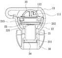
- FIG. 1is a perspective view of an in-ear earphone according to a preferred embodiment of the present invention.
- FIG. 2is an exploded perspective view of the in-ear earphone depicted in FIG. 1 ;
- FIG. 3is a cross-sectional view of the in-ear earphone depicted in FIG. 1 ;
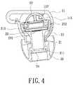
- FIG. 4is another cross-sectional view of the in-ear earphone depicted in FIG. 1 , wherein the sound output device is adjusted by an angle relative to the shell;
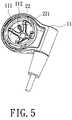
- FIG. 5is a magnified view of a portion of the in-ear earphone depicted in FIG. 1 ;
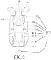
- FIG. 6is a cross-sectional view of an in-ear earphone according to another preferred embodiment of the present invention.
- an in-ear earphone 1according to a preferred embodiment of the present invention is provided.
- the in-ear earphone 1includes a shell 10 , a sound output device 20 and a cushion 30 .
- One end of the sound output device 20is moveably disposed in the shell 10 , and another end of the sound output device 20 is wrapped around by the cushion 30 .
- the shell 10has a base 11 and a cover 12 .
- the base 11 and the cover 12both have a half spherical surface respectively.
- the cover 12is covered on the base 11 , such half spherical surface is connected to form a cell that roughly has a ball shape.
- This cellfunctions as a first engaging portion 111 , referring to FIG. 3 , for accommodating the sound output device 20 .
- the sound output device 20has a sound tunnel 21 , a second engaging portion 22 , a speaker 23 and a grid cover 24 .
- the sound tunnel 21has an opening end 211 and a containing portion 212 .
- the grid cover 24is disposed inside the opening end 211 for preventing dust from entering the sound tunnel 21 .
- the outside of the opening end 211is wrapped around by a cushion 30 .
- the cushion 30is made of an elastic material that is particularly suitable for being plugged into user's ear canals.
- the containing portion 212 of the sound tunnel 21has a radius greater than the radius of the opening end 211 so as to accommodate the speaker 23 .
- a sound outputting surface of the speaker 23is installed to be facing the opening end 211 and the speaker 23 is coaxially aligned with the sound tunnel 21 .
- the second engaging portion 22is a cover of a half ball shape, on which there are four positioning holes 221 are formed. Referring to FIG. 2 , the outside wall of the containing portion 212 of the sound tunnel 21 also has a curved shape. When the second engaging portion 22 is covered on the containing portion 212 of the sound tunnel 21 , the curved surfaces are combined to form a shape close to a ball. This ball is further combined with the first engaging portion 111 of the shell 10 and accommodated inside the shell 10 . The second engaging portion 22 can be adjusted in angles relative to the first engaging portion 111 .
- the sound tunnel 21is made of polyoxymethylene (POM) or acrylonitrile butadiene styrene (ABS).
- the second engaging portion 22is made of acrylonitrile butadiene styrene (ABS) or polyoxymethylene (POM), which acrylonitrile butadiene styrene (ABS) is soft and polyoxymethylene (POM) is suitable for rubbing against.
- a plurality of protrusions 213are formed on an outer wall of the containing portion 212 of the sound tunnel 21 .
- the protrusions 213touch the inner wall of the cover 12 .
- FIG. 4when the user pushes the sound output device 20 so that there is an angle between the sound output device 20 and the shell 10 , the protrusions 213 on the sound tunnel 21 rub the inner wall of the cover 12 accordingly, so as to prevent excessive movement of the sound output device 20 .
- the speaker 23is coaxially disposed on the containing portion 212 of the sound tunnel 21 along with the sound tunnel 21 , no matter how the sound output device 20 changes its angle relative to the shell 10 , the sound outputting surface 231 of the speaker 23 is always exactly facing the opening end 211 .
- the four positioning holes 221are formed through the second engaging portion 22 .
- a stopping device 112is fixedly disposed on the base 11 .
- the second engaging portion 22moves relative to the base 11 , the range of its movement is limited by the positioning holes 221 , that is, when the second engaging portion 22 moves to a position where it touches with the stopping device 112 or the positioning hole 221 , the second engaging portion 22 can not move in the same direction any more. In that case, the second engaging portion 22 can only move in an opposite direction. Thus, excessive angular movement of the sound output device 20 relative to the shell 10 can be prevented.
- the first engaging portion 111is monolithically formed to be extended from the shell 10 , and has a shape close to a ball.
- a wire groove 13is disposed through the first engaging portion 111 and the shell 10 so that a wire of the speaker 23 can be pulled out from the wire groove 13 .
- the second engaging portion 22 of the sound output device 20has a tube shape. An end of the second engaging portion 22 is connected to the containing portion 212 of the sound tunnel 21 and another end of the second engaging portion 22 has a cell 222 , which has a curved surface and is configured for combining with the first engaging portion 111 .
- the sound output device 20can be adjusted in angles toward the shell 10 .
- a plurality of protrusions 223are formed on the curved surface of the cell 222 .
- the protrusions 223can prevent any excessive movement by exerting friction force.
- the sound output devicewhich can be plugged into a user's canal, of the in-ear earphone according to the embodiments of the present invention can be adjusted in its angle with the shell of the earphone so that when different users use the earphone, the users can adjust the sound output device to make it fit their ear canals. Because the speaker is disposed in the sound output device, the direction in which the speaker outputs sound to the sound tunnel do not vary with the angular adjustment of the sound output device. As a result, the sound output characteristics of the earphone are not disturbed by the adjustment.
- the configuration of the positioning holes of the second engaging portion and the stopping device and the configuration of the protrusions on the sound tunnel and the first engaging portioncan prevent excessive angular adjustments between the sound output device and the shell so as to avoid unintended adjustments and inability of positioning during use.
Landscapes
- Physics & Mathematics (AREA)
- Engineering & Computer Science (AREA)
- Acoustics & Sound (AREA)
- Signal Processing (AREA)
- Headphones And Earphones (AREA)
Abstract
Description
Claims (12)
Priority Applications (1)
| Application Number | Priority Date | Filing Date | Title |
|---|---|---|---|
| US12/264,302US8213668B2 (en) | 2008-11-04 | 2008-11-04 | In-ear earphone |
Applications Claiming Priority (1)
| Application Number | Priority Date | Filing Date | Title |
|---|---|---|---|
| US12/264,302US8213668B2 (en) | 2008-11-04 | 2008-11-04 | In-ear earphone |
Publications (2)
| Publication Number | Publication Date |
|---|---|
| US20100111348A1 US20100111348A1 (en) | 2010-05-06 |
| US8213668B2true US8213668B2 (en) | 2012-07-03 |
Family
ID=42131440
Family Applications (1)
| Application Number | Title | Priority Date | Filing Date |
|---|---|---|---|
| US12/264,302Active2030-12-27US8213668B2 (en) | 2008-11-04 | 2008-11-04 | In-ear earphone |
Country Status (1)
| Country | Link |
|---|---|
| US (1) | US8213668B2 (en) |
Cited By (9)
| Publication number | Priority date | Publication date | Assignee | Title |
|---|---|---|---|---|
| USD676426S1 (en)* | 2011-12-30 | 2013-02-19 | Sony Corporation | Earphone |
| US20130294634A1 (en)* | 2012-05-03 | 2013-11-07 | Hon Hai Precision Industry Co., Ltd. | Earphone set with interchangeable in-ear and in-concha caps |
| USD736185S1 (en)* | 2013-12-27 | 2015-08-11 | Sony Corporation | Earphone |
| US20170127176A1 (en)* | 2015-11-03 | 2017-05-04 | Acer Incorporated | Electronic device |
| CN106714046A (en)* | 2015-11-18 | 2017-05-24 | 宏碁股份有限公司 | Electronic device |
| USD798844S1 (en)* | 2015-12-04 | 2017-10-03 | Sony Interactive Entertainment Inc. | Earphone |
| US10959010B1 (en)* | 2019-11-19 | 2021-03-23 | Merry Electronics(Shenzhen) Co., Ltd. | Earphone device |
| USD963611S1 (en)* | 2020-05-04 | 2022-09-13 | Jawb Acquisition, Llc | Earphone |
| US12185046B1 (en)* | 2021-06-25 | 2024-12-31 | Jay S Derman | Ear supported audio device |
Families Citing this family (11)
| Publication number | Priority date | Publication date | Assignee | Title |
|---|---|---|---|---|
| US8891799B2 (en)* | 2008-06-04 | 2014-11-18 | JVC Kenwood Corporation | Earphone |
| JP2011101224A (en)* | 2009-11-06 | 2011-05-19 | Victor Co Of Japan Ltd | Headphone and stereo headphone |
| US8401218B2 (en)* | 2010-07-29 | 2013-03-19 | Microsoft Corporation | Adjustable earphone and earphone set |
| CN107534807A (en)* | 2015-01-07 | 2018-01-02 | 泰洛斯声学有限责任公司 | With the earphone into horn and nozzle |
| TWI596952B (en)* | 2016-03-21 | 2017-08-21 | 固昌通訊股份有限公司 | In-ear earphone |
| DE102017207528A1 (en)* | 2017-05-04 | 2018-11-08 | Sivantos Pte. Ltd. | Module for installation in a hearing aid |
| DE102017210447A1 (en)* | 2017-06-21 | 2018-12-27 | Sivantos Pte. Ltd. | hearing Aid |
| EP3585064A1 (en)* | 2018-06-20 | 2019-12-25 | B&B Electronics AG | Earphone |
| CN111510811B (en)* | 2020-04-22 | 2022-10-18 | 歌尔科技有限公司 | Earphone set |
| EP4175318B1 (en)* | 2021-10-29 | 2024-03-20 | JVCKENWOOD Corporation | Ear mount |
| DE102023202591B4 (en)* | 2023-03-22 | 2025-01-09 | Sivantos Pte. Ltd. | Loudspeaker system for an in-ear hearing aid |
Citations (14)
| Publication number | Priority date | Publication date | Assignee | Title |
|---|---|---|---|---|
| JPH04348166A (en)* | 1990-10-13 | 1992-12-03 | Bridgestone Corp | Sound absorbing resin composition |
| CN2415568Y (en) | 2000-04-04 | 2001-01-17 | 黄大伟 | triangle earphones |
| US20020080990A1 (en)* | 1999-07-06 | 2002-06-27 | Lin Chung Yu | Earphone without impulse noise and surroundings blockade |
| JP2004148186A (en)* | 2002-10-30 | 2004-05-27 | Meidensha Corp | Apparatus for detecting water level of scum removing apparatus |
| TWM273162U (en) | 2005-03-11 | 2005-08-11 | Obo Pro 2 Inc | Earplug earphone |
| US20070098201A1 (en)* | 2005-11-02 | 2007-05-03 | Chung-Hsien Chen | Earplug type earphone |
| US20080031481A1 (en)* | 2006-05-30 | 2008-02-07 | Knowles Electronics, Llc | Personal listening device |
| US20080107299A1 (en)* | 2006-11-03 | 2008-05-08 | I-Ming Lin | Earphone |
| US20080267438A1 (en)* | 2007-04-26 | 2008-10-30 | Yi-Rong Chen | Earphone and tuning module of speaker for the earphone |
| US20090116677A1 (en)* | 2007-10-31 | 2009-05-07 | Thx Ltd. | Earphone device |
| US20090136074A1 (en)* | 2007-11-27 | 2009-05-28 | Ching-Wen Chang | Earphone and the Method of Making thereof |
| US20090233652A1 (en)* | 2008-03-17 | 2009-09-17 | Jen-Han Yang | Speaker with earphone function |
| US20090279729A1 (en)* | 2008-05-08 | 2009-11-12 | Jetvox Acoustic Corp. | Dual-frequency coaxial earphones |
| US20100177904A1 (en)* | 2009-01-13 | 2010-07-15 | Po-Hsun Sung | Noise Reducing Earphone |
- 2008
- 2008-11-04USUS12/264,302patent/US8213668B2/enactiveActive
Patent Citations (14)
| Publication number | Priority date | Publication date | Assignee | Title |
|---|---|---|---|---|
| JPH04348166A (en)* | 1990-10-13 | 1992-12-03 | Bridgestone Corp | Sound absorbing resin composition |
| US20020080990A1 (en)* | 1999-07-06 | 2002-06-27 | Lin Chung Yu | Earphone without impulse noise and surroundings blockade |
| CN2415568Y (en) | 2000-04-04 | 2001-01-17 | 黄大伟 | triangle earphones |
| JP2004148186A (en)* | 2002-10-30 | 2004-05-27 | Meidensha Corp | Apparatus for detecting water level of scum removing apparatus |
| TWM273162U (en) | 2005-03-11 | 2005-08-11 | Obo Pro 2 Inc | Earplug earphone |
| US20070098201A1 (en)* | 2005-11-02 | 2007-05-03 | Chung-Hsien Chen | Earplug type earphone |
| US20080031481A1 (en)* | 2006-05-30 | 2008-02-07 | Knowles Electronics, Llc | Personal listening device |
| US20080107299A1 (en)* | 2006-11-03 | 2008-05-08 | I-Ming Lin | Earphone |
| US20080267438A1 (en)* | 2007-04-26 | 2008-10-30 | Yi-Rong Chen | Earphone and tuning module of speaker for the earphone |
| US20090116677A1 (en)* | 2007-10-31 | 2009-05-07 | Thx Ltd. | Earphone device |
| US20090136074A1 (en)* | 2007-11-27 | 2009-05-28 | Ching-Wen Chang | Earphone and the Method of Making thereof |
| US20090233652A1 (en)* | 2008-03-17 | 2009-09-17 | Jen-Han Yang | Speaker with earphone function |
| US20090279729A1 (en)* | 2008-05-08 | 2009-11-12 | Jetvox Acoustic Corp. | Dual-frequency coaxial earphones |
| US20100177904A1 (en)* | 2009-01-13 | 2010-07-15 | Po-Hsun Sung | Noise Reducing Earphone |
Cited By (12)
| Publication number | Priority date | Publication date | Assignee | Title |
|---|---|---|---|---|
| USD676426S1 (en)* | 2011-12-30 | 2013-02-19 | Sony Corporation | Earphone |
| US20130294634A1 (en)* | 2012-05-03 | 2013-11-07 | Hon Hai Precision Industry Co., Ltd. | Earphone set with interchangeable in-ear and in-concha caps |
| USD736185S1 (en)* | 2013-12-27 | 2015-08-11 | Sony Corporation | Earphone |
| US20170127176A1 (en)* | 2015-11-03 | 2017-05-04 | Acer Incorporated | Electronic device |
| US9860632B2 (en)* | 2015-11-03 | 2018-01-02 | Acer Incorporated | Electronic device |
| US10194237B2 (en) | 2015-11-03 | 2019-01-29 | Acer Incorporated | Electronic device |
| CN106714046A (en)* | 2015-11-18 | 2017-05-24 | 宏碁股份有限公司 | Electronic device |
| CN106714046B (en)* | 2015-11-18 | 2019-08-16 | 宏碁股份有限公司 | Electronic device |
| USD798844S1 (en)* | 2015-12-04 | 2017-10-03 | Sony Interactive Entertainment Inc. | Earphone |
| US10959010B1 (en)* | 2019-11-19 | 2021-03-23 | Merry Electronics(Shenzhen) Co., Ltd. | Earphone device |
| USD963611S1 (en)* | 2020-05-04 | 2022-09-13 | Jawb Acquisition, Llc | Earphone |
| US12185046B1 (en)* | 2021-06-25 | 2024-12-31 | Jay S Derman | Ear supported audio device |
Also Published As
| Publication number | Publication date |
|---|---|
| US20100111348A1 (en) | 2010-05-06 |
Similar Documents
| Publication | Publication Date | Title |
|---|---|---|
| US8213668B2 (en) | In-ear earphone | |
| US9445185B2 (en) | Audio listening system | |
| US8447060B2 (en) | Earphone | |
| US6178251B1 (en) | Collar microphone | |
| KR20070049946A (en) | Insert earphones with earrings | |
| US20090285434A1 (en) | Earhook and earbud headset | |
| US20030059071A1 (en) | Personal audio device with hearing protection | |
| US20090097690A1 (en) | Adjustable earphone | |
| US20200059715A1 (en) | Earphone | |
| US20130177193A1 (en) | Earbud or in-ear headphone clip | |
| CN101322434A (en) | Earphone and method of using earphone | |
| WO2015057750A1 (en) | Headset with ball joint allowing rotation of earpieces in multiple axes | |
| CN205081917U (en) | Multi-Ear Hook Switchable Headphones | |
| US20060147079A1 (en) | Earphone | |
| CN103686506A (en) | Headphone unit | |
| CN205081918U (en) | Ear hanging earphone | |
| CN205081916U (en) | Earhook Headphones | |
| US12047725B2 (en) | Adaptive eartip for true wireless stereo headsets | |
| CN209608820U (en) | In-Ear Headphones | |
| KR101382528B1 (en) | Eartip and earphone | |
| TWI831019B (en) | In-ear headphone | |
| CN221553420U (en) | Ear cap and earphone | |
| TWI834989B (en) | Earphone with adjustable microphone | |
| CN207340126U (en) | In-Ear anticreep earphone | |
| JP3155362U (en) | headphone |
Legal Events
| Date | Code | Title | Description |
|---|---|---|---|
| AS | Assignment | Owner name:MERRY ELECTRONICS CO., LTD.,TAIWAN Free format text:ASSIGNMENT OF ASSIGNORS INTEREST;ASSIGNORS:TSAO, CHING-JUNG;LIN, I-MING;REEL/FRAME:021780/0284 Effective date:20080901 Owner name:MERRY ELECTRONICS CO., LTD., TAIWAN Free format text:ASSIGNMENT OF ASSIGNORS INTEREST;ASSIGNORS:TSAO, CHING-JUNG;LIN, I-MING;REEL/FRAME:021780/0284 Effective date:20080901 | |
| STCF | Information on status: patent grant | Free format text:PATENTED CASE | |
| FEPP | Fee payment procedure | Free format text:PAYOR NUMBER ASSIGNED (ORIGINAL EVENT CODE: ASPN); ENTITY STATUS OF PATENT OWNER: LARGE ENTITY | |
| FPAY | Fee payment | Year of fee payment:4 | |
| MAFP | Maintenance fee payment | Free format text:PAYMENT OF MAINTENANCE FEE, 8TH YEAR, LARGE ENTITY (ORIGINAL EVENT CODE: M1552); ENTITY STATUS OF PATENT OWNER: LARGE ENTITY Year of fee payment:8 | |
| MAFP | Maintenance fee payment | Free format text:PAYMENT OF MAINTENANCE FEE, 12TH YEAR, LARGE ENTITY (ORIGINAL EVENT CODE: M1553); ENTITY STATUS OF PATENT OWNER: LARGE ENTITY Year of fee payment:12 |