US8213299B2 - Methods and systems for locating redundant telephony call processing hosts in geographically separate locations - Google Patents
Methods and systems for locating redundant telephony call processing hosts in geographically separate locationsDownload PDFInfo
- Publication number
- US8213299B2 US8213299B2US10/666,217US66621703AUS8213299B2US 8213299 B2US8213299 B2US 8213299B2US 66621703 AUS66621703 AUS 66621703AUS 8213299 B2US8213299 B2US 8213299B2
- Authority
- US
- United States
- Prior art keywords
- lan
- call processing
- telephony call
- geographic region
- segment
- Prior art date
- Legal status (The legal status is an assumption and is not a legal conclusion. Google has not performed a legal analysis and makes no representation as to the accuracy of the status listed.)
- Active, expires
Links
Images


Classifications
- H—ELECTRICITY
- H04—ELECTRIC COMMUNICATION TECHNIQUE
- H04L—TRANSMISSION OF DIGITAL INFORMATION, e.g. TELEGRAPHIC COMMUNICATION
- H04L65/00—Network arrangements, protocols or services for supporting real-time applications in data packet communication
- H04L65/80—Responding to QoS
- H—ELECTRICITY
- H04—ELECTRIC COMMUNICATION TECHNIQUE
- H04L—TRANSMISSION OF DIGITAL INFORMATION, e.g. TELEGRAPHIC COMMUNICATION
- H04L1/00—Arrangements for detecting or preventing errors in the information received
- H04L1/22—Arrangements for detecting or preventing errors in the information received using redundant apparatus to increase reliability
- H—ELECTRICITY
- H04—ELECTRIC COMMUNICATION TECHNIQUE
- H04L—TRANSMISSION OF DIGITAL INFORMATION, e.g. TELEGRAPHIC COMMUNICATION
- H04L65/00—Network arrangements, protocols or services for supporting real-time applications in data packet communication
- H04L65/1066—Session management
- H04L65/1101—Session protocols
- H04L65/1104—Session initiation protocol [SIP]
- H—ELECTRICITY
- H04—ELECTRIC COMMUNICATION TECHNIQUE
- H04L—TRANSMISSION OF DIGITAL INFORMATION, e.g. TELEGRAPHIC COMMUNICATION
- H04L65/00—Network arrangements, protocols or services for supporting real-time applications in data packet communication
- H04L65/1066—Session management
- H04L65/1101—Session protocols
- H04L65/1106—Call signalling protocols; H.323 and related
- H—ELECTRICITY
- H04—ELECTRIC COMMUNICATION TECHNIQUE
- H04M—TELEPHONIC COMMUNICATION
- H04M7/00—Arrangements for interconnection between switching centres
- H04M7/006—Networks other than PSTN/ISDN providing telephone service, e.g. Voice over Internet Protocol (VoIP), including next generation networks with a packet-switched transport layer
- H—ELECTRICITY
- H04—ELECTRIC COMMUNICATION TECHNIQUE
- H04L—TRANSMISSION OF DIGITAL INFORMATION, e.g. TELEGRAPHIC COMMUNICATION
- H04L2101/00—Indexing scheme associated with group H04L61/00
- H04L2101/60—Types of network addresses
- H04L2101/604—Address structures or formats
- H—ELECTRICITY
- H04—ELECTRIC COMMUNICATION TECHNIQUE
- H04M—TELEPHONIC COMMUNICATION
- H04M3/00—Automatic or semi-automatic exchanges
- H04M3/08—Indicating faults in circuits or apparatus
- H—ELECTRICITY
- H04—ELECTRIC COMMUNICATION TECHNIQUE
- H04M—TELEPHONIC COMMUNICATION
- H04M3/00—Automatic or semi-automatic exchanges
- H04M3/08—Indicating faults in circuits or apparatus
- H04M3/12—Marking faulty circuits "busy"; Enabling equipment to disengage itself from faulty circuits ; Using redundant circuits; Response of a circuit, apparatus or system to an error
Definitions
- the present inventionrelates to methods and systems for locating redundant telephony call processing hosts, such as redundant media gateway controllers and redundant SIP proxy servers, in geographically diverse locations.
- IP telephony call processing hostssuch as media gateway controllers
- media gateway controllershave been deployed in redundant pairs.
- these redundant pairsare often located in the same physical frame, making the active and standby host susceptible to simultaneous failure due to a power outage, fire, or other occurrence at the site where the physical frame is located.
- telephony call processing hostrefers to a physical entity in a telephony network
- telephony call processing noderefers to a logical entity in a telephony call processing network.
- a nodemay include two or more physical hosts, where the hosts are located in the same or in different geographic locations. When a node consists of two redundant hosts, each host may also be referred to as a half-node.
- a dual-host telephony call processing systemincludes one active and one standby host. In case of a hardware or software failure, a switchover occurs and the two hosts switch roles.
- telephony call processing hostsPrior to the present invention, telephony call processing hosts were deployed in the same physical frame, at the same location. Therefore, this solution did not offer redundancy for a complete site failure, for example an earthquake that affects a building.
- the typical solution for providing site redundancywas to use two multi-host nodes, one at each site. But this has several disadvantages: it doubles the cost of the solution, and it also complicates the network topology (provisioning and maintenance).
- two telephony call processing hostsmay now be deployed in two different frames, located at different sites. This can be done using the same application software that the telephony call processing hosts normally uses; however, some aspects of the network architecture (topology), as well as the network configuration, are different in a multi-site solution.
- half of the telephony call processing equipmentis located at one site and the other half is located at another site (e.g. in two different buildings or even in two different cities).
- Thisincludes distributing a call processing node (two physical hosts) between the sites and exchanging state information from one of the telephony call processing hosts to the other telephony call processing host. If any site suffers a complete failure, one of the two LANs is still available for communications.
- Two LAN switchesare required to provide redundant LANs at each site. Also, two routers are required so that both telephony call processing hosts have redundant connections to the service provider's network.
- Interconnecting the LAN segmentsis relatively simple to do when the two sites are in two locations that are close enough to each other. In this case, an extended LAN connection can be provided. If the two sites are located far away from each other, possibly in different cities, then the interconnections must be provided over WAN links.
- This solutioninvolves transparent LAN bridging over a WAN, which is the technique of interconnecting LAN segments over a WAN such that, together, they still form a single IP subnet (the same LAN).
- site redundancyWith the introduction of site redundancy, a new, standardized IP addressing scheme has been implemented. This scheme is consistent for either the normal or site redundant configuration. The scheme is flexible in that it can fit into an existing customer network, as long as two blocks of IP addresses can be allocated to the telephony call processing host components.
- An additional feature of the inventionis the ability to provide additional redundancy by adding a half system (single host).
- a half systemsingle host
- multiple nodesfor example, N dual-hosts, i.e. 2N hosts
- splitting nodes between siteshas the benefit of if a site fails (e.g., due to a natural disaster), service can be preserved.
- a disadvantage of using one host in each geographically separated siteis that repairing the failed site can take a long time, during which the remaining host runs in simplex mode, where it is vulnerable to normal hardware/software failures.
- one implementation of the inventionincludes adding an additional half-system (one host) that can take over the role of any other failed host in the system, at any time.
- the site redundancy conceptcan be extended to any telephony call processing node, such as a SIP proxy server, an H.323 gatekeeper, a telephony feature server that terminates the media stream and provides telephony services, such as call waiting or call forwarding, or a telephony application server that provides database-related telephony services, such as number portability.
- a telephony call processing nodesuch as a SIP proxy server, an H.323 gatekeeper, a telephony feature server that terminates the media stream and provides telephony services, such as call waiting or call forwarding, or a telephony application server that provides database-related telephony services, such as number portability.
- FIG. 1is a block diagram of an exemplary network architecture for providing geographically separate redundant telephony call processing hosts according to an embodiment of the present invention
- FIG. 2is a block diagram illustrating LAN bridging suitable for interconnecting geographically separate redundant telephony call processing hosts according to an embodiment of the present invention
- FIG. 3is a block diagram illustrating transparent LAN bridging over a WAN suitable for communicating between geographically separate redundant telephony call processing hosts according to an embodiment of the present invention.
- FIG. 4is a block diagram illustrating Ethernet to ATM bridging in a WAN access router at one host of a pair of geographically separate redundant telephony call processing hosts according to an embodiment of the present invention
- FIG. 5is a block diagram illustrating exemplary ATM switched permanent virtual circuit bridging between geographically separate redundant telephony call processing hosts according to an embodiment of the present invention
- FIG. 6is a block diagram illustrating bridging using a customer's IP network between geographically separate redundant telephony call processing hosts according to an embodiment of the present invention
- FIG. 7illustrates another example of bridging in a customer's interconnecting routers between geographically separate redundant telephony call processing hosts according to an embodiment of the present invention
- FIG. 8is a block diagram illustrating bridging in a customer's interconnecting routers to interconnect geographically separate redundant telephony call processing hosts according to an embodiment of the present invention
- FIG. 9illustrates exemplary bridging performed in an isolation router between geographically separate redundant telephony call processing hosts according to an embodiment of the present invention
- FIG. 10is a block diagram illustrating bridging performed by isolation routers between geographically separate redundant telephony call processing hosts according to an embodiment of the present invention
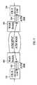
- FIG. 11is a block diagram illustrating conventional subnet masking
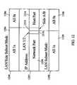
- FIG. 12is a block diagram illustrating exemplary LAN/side subnet masking performed in isolation routers that interconnect geographically separate redundant telephony call processing hosts according to an embodiment of the present invention
- FIG. 13is a block diagram illustrating exemplary routing assuming standard subnet masking.
- FIG. 14is a block diagram illustrating exemplary customer routing assuming LAN/side subnet masking and site redundancy between telephony call processing hosts according to an embodiment of the present invention.
- FIG. 1illustrates an exemplary network architecture for providing geographically separate redundant telephony call processing hosts according to an embodiment of the present invention.
- a first telephony call processing host 100resides at site A 102 and a second telephony call processing host 104 resides at site B 106 .
- Telephony call processing hosts 100 and 104may be any type of packet telephony call processing hosts, such as media gateway controllers, SIP proxy servers, H.323 gate keepers, etc.
- Sites 102 and 106may be separated by any suitable geographic distance to ensure site redundancy so that a natural disaster at one site has a reduced likelihood of affecting the other site.
- hosts 100 and 104are interconnected via two LANs, LAN 1 and LAN 2 bridged over a WAN.
- both LAN 1 and LAN 2are distributed between site A 102 and site B 106 . That is, LAN 1 has a first side located at site A and a second side located at site B. Similarly, LAN 2 has a first side located at site A and a second side located at site B.
- a novel subnetting schemethat allows routers to distinguish between the LAN and side for each LAN/side illustrated in FIG. 1 will be described in detail below.
- Communication from site A 102 to site B 106 via LAN 1occurs using LAN switch A 108 , router A 110 , LAN switch A 1 112 , and router A 1 114 .
- communication between site A 102 and site B 106 via LAN Boccurs via LAN switch B 116 , router B 118 , LAN switch B 1 120 , and router B 1 122 .
- FIG. 1Also shown in FIG. 1 is a customer's interconnecting IP network 122 including a plurality of routers 124 , a media gateway 126 , and a SIP proxy server 128 .
- a customer's interconnecting IP network 122including a plurality of routers 124 , a media gateway 126 , and a SIP proxy server 128 .
- one method for interconnecting site A and site B according to the present inventionreduces the need to update the routing tables in each of the routers 124 .
- FIG. 2illustrates exemplary configuration of a router in the interconnecting WAN for transparent LAN bridging using a bridge virtual interface (BVI) group.
- BVIbridge virtual interface
- a routercannot have more than one interface connected to the same LAN, i.e., with the same IP address and subnet mask. However, if these interfaces connect to different segments of the same LAN, they can be interconnected and declared part of the same bridge virtual interface group.
- a bridge virtual interface groupis a collection of interfaces on a router which together act as a single interface connected to a single subnet. For IP routing purposes, the interfaces in the BVI group share a single subnet address mask that corresponds to the virtual subnet (LAN) consisting of several segments.
- a router 200includes three interfaces, I 1 , I 2 , and I 3 .
- the routing function in router 200delivers IP packets between the interfaces based on the destination IP address.
- I 1which is a BVI
- the bridging functiondetermines to which physical interface within the bridge it must deliver the packet.
- the bridging functionmaintains an internal ARP table associated with the BVI, which specify the IP addresses that have been associated with the MAC addresses via ARP broadcast.
- the ARP tablealso indicates which physical interface within the BVI the ARP broadcast has been received.
- the bridge virtual interfaceinterconnects LAN switch A 108 and LAN switch A 1 114 .
- LAN switch A 108 and LAN switch A 1 114are on the same subnet 200 . 1 but are connected to different interfaces on router 200 .
- the bridge virtual interface feature of router 200enables such interconnection to occur.
- FIG. 2illustrates bridging between geographically separate subnets using a single router
- the interfaces that need to be bridgedare located remotely from each other. Therefore, bridging over a WAN is required.
- FIG. 3illustrates a generic solution for transparent LAN bridging over a WAN.
- LAN switches LAN switch A 108 and LAN switch A 1 112need to be bridged.
- the bridgingis performed by router A 110 and router A 1 114 . Exemplary protocols for performing the WAN bridging will be described in more detail below.
- redundant telephony call processing hostscan be bridged in a number of different manners. Three methods for bridging between geographically separate redundant telephony call processing hosts will now be described in detail. The first two methods use the interconnecting or customer equipment. The third method uses the isolation routers.
- FIG. 4illustrates exemplary bridging performed by a customer router 124 and customer WAN switch 400 .
- IP traffic that needs to be bridged from LAN switch A 108enters router 124 over an Ethernet interface.
- Router 124has a WAN interface, such as a point-to-point ATM link, to switch 400 , which is the first switch in the WAN.
- Bridgingis performed over a dedicated permanent virtual circuit (PVC) on the ATM link.
- PVCpermanent virtual circuit
- the permanent virtual circuitwill be defined by a VPI.VCI value, such as 0.100, shown in FIG. 4 .
- the Ethernet interface from LAN switch A 108 and the ATM PVC used for bridgingmust be part of the same bridge virtual interface group.
- FIG. 5illustrates both ends of the connection corresponding to the diagram in FIG. 4 .
- the remote end of the connectionconsists of a WAN switch 500 , a customer router CR-X 124 , and an ATM link 504 interconnecting WAN switch 500 and CR-Y 124 .
- a similar BVI groupmay be used at the remote end of the connection to interconnect the LAN segments.
- the WAN switchesmay be interconnected by an ATM PVC or SPVC, depending on the particular ATM switching equipment used.
- FIG. 6is a network architecture diagram illustrating interconnection of the redundant telephony call processing hosts using the customer's interconnecting routers and WAN switches as described in FIGS. 4 and 5 .
- remote sites 102 and 106are interconnected via customer routers 124 and WAN switches 400 , 500 , 600 , and 602 .
- customer routersneed to be modified in order to perform the bridging.
- bridgingmay be performed using an interconnecting customer network; however, the impact on the geographically distributed telephony call processing host is minimized.
- redundant telephony call processing hostsmay be bridged by sharing the interconnecting WAN with a customer's IP overlay network.
- FIGS. 7 and 8illustrate this bridging solution.
- both LAN switch A 108 and router A 120include Ethernet interfaces that connect with Ethernet interface on customer router A 124 .
- Customer router A 124interconnects with a LAN switch 700 via an ATM PVC.
- customer router A 124 and customer router A 1 124are interconnected via a WAN bridge implemented by WAN switches 700 and 800 .
- customer router B 1 and 124 and customer router B 124are interconnected via a WAN bridge implemented via WAN switches 802 and 804 .
- FIG. 8is that in FIG. 6 , separate WAN and IP networks are used to interconnect routers and LAN switches at the remote ends of the connection. In FIG. 8 , all routers and LAN switches are interconnected over the same WAN backbone. Thus, the system illustrated in FIG. 8 requires a reduced number of components than the system illustrated in FIG. 6 .
- the solution illustrated in FIG. 8is suitable when a customer's IP network is an overlay network over an existing WAN backbone.
- FIG. 9illustrates exemplary bridging performed by isolation routers according to an embodiment of the present invention.
- router A 110is connected to WAN switch 900 in a customer's network over an ATM or frame relay link, rather than connecting to edge routers in a customer's IP network via Ethernet links as described in the solutions above.
- integrate bridging and routingmust be performed in router A 110 , as shown in FIG. 9 .
- the other routing interfaces denoted as “other VPI.VCIs” in FIG. 9are SPVCs used as point-to-point links to other routers. These interfaces are similar to the interfaces described above in FIG. 5 . Alternately, if WAN switch 900 can perform both switching and routing, then these additional SPVCs are not necessary. A single PVC, for example, 0.101, can be used for routed traffic. This interface constitutes a routed interface on WAN switch 900 . Traffic to this interface is not directly relayed to an SPVC. Similar routing considerations may be applied to router A 114 , router B 116 , and router B 1 120 illustrated in FIG. 1 . Exemplary isolation routers suitable for implementing the solution illustrated in FIG. 9 are any of the routers available from Cisco Systems, Inc. and/or many other vendors.
- FIG. 10illustrates an example of bridging using isolation routers according to an embodiment of the present invention.
- bridgingis performed using isolation routers 110 , 114 , 118 , and 122 .
- Each isolation routerconnects to a WAN switch 1000 located in the customer's WAN backbone.
- bridgingcan be performed without requiring modification to routers in the customer's IP network.
- IP addressing for network components of a geographically distributed redundant telephony call processing hostpreferably minimize the IP addresses consumed and the impact on the interconnecting routers.
- IP addressing schemeis preferably easy to implement and transparent to application level software whether site redundancy is utilized or not. In order to implement these addressing rules, a classless addressing scheme using subnetting may be used.
- FIG. 11illustrates conventional subnetting.
- a subnet mask 1100may be applied to an IP address 1102 in order to implement IP subnetting. More particularly, subnet mask 1100 includes a first portion 1104 consisting of all ones and a second portion 1106 consisting of all zeros. IP address 1102 is divided into a network part 1108 , a subnet part 1110 , and a host part 1112 .
- Network part 1108identifies the network to which a packet is addressed.
- Subnet part 1110allows a physical network to be divided into multiple subnets.
- Host part 1112identifies the host on an individual subnet.
- Subnet mask 1100is AND with destination IP addresses in incoming packets and compared with the corresponding entries to determine a next top address for the incoming packet.
- FIG. 12illustrates LAN/side subnetting according to the present invention.
- a LAN/side subnet mask 1200is applied to an IP address 1202 when comparing the IP address to routing table entries.
- LAN/side subnet mask 1200includes a first portion 1204 that is all ones and a second portion 1206 that is all zeros used to mask out the host part of the IP address.
- IP address 1202allows IP address 1202 to include a network part 1208 , a LAN part 1210 , a side part 1212 , and a host part 1214 .
- Network part 1208identifies the IP network, as subnet masks.
- LAN part 1210identifies the LAN of a redundant telephony call processing host.
- Side part 1212identifies the side, i.e., A or B of the LAN.
- Host part 1214identifies the particular host on the particular LAN/side.
- LAN subnet mask 1100is also required in the exemplary implementation of redundant telephony call processing hosts as described herein.
- LAN subnet mask 1100is used to distinguish between internal LAN subnets 1 and 2 .
- LAN/side subnet mask 1200is used to distinguish among the four combinations of the two LANs and the two sides.
- the two types of addressingare represented by one bit each in the subnet mask. When used together, the two bits allow discrimination between four quadrants of the overall redundant telephony call processor address space: LAN 1 /side A, LAN 1 /side B, LAN 2 /side A, and LAN 2 /side B.
- Either of the subnet masks illustrated in FIG. 12may be used for routing, depending on the network configuration.
- the LAN/side subnet maskmay be used in the customer's network routers to allow four way routing in the site redundancy case while the LAN subnet mask may be used to allow two way routing in a standard single site case.
- Two address spaceseach consisting of for example 64 continuous addresses may be reserved for implementing site redundancy according to the present invention. Reserving 64 addresses allows for a maximum of 62 addresses on each of two LAN subnets (addresses with all ones or all zeros are not allowed).
- a host part addressconsists of a minimum five bit component plus a one bit side or site A/B indicator. For the indicator bit, a value of zero may indicate side A and a value of one may indicate side B.
- the two address spacesneed not be contiguous with each other. However, each range of 64 addresses is preferably on a multiple of 64 boundary (e.g.: 0, 64, 128, etc.) Within these ranges the corresponding side A and B components will have addresses that are offset by 32 from each other.
- the number 64is provided here as an example only. The actual number depends on the total number of IP addresses required by the telephony node as well as by all the additional equipment hosted on the two LANs.
- Exemplary rules for two LAN based addresses and two subnet masksmay be as follows:
- the LAN 1 base addressis chosen as 192.168.200.0 and the LAN 2 base address is chosen as 192.168.200.64.
- the binary equivalentsare: 11000000.10101000.11001000.00000000 and 11000000.10101000.11001000.01000000.
- the right-most 1-bitis in the “64” column, so the byte value is 192.
- the LAN subnet maskis 255.255.255.192
- the LAN/side subnet maskis 255.255.255.224.
- a customerdesires to use an existing set of network addresses with subnets identified as 172.25.216.0 and 172.25.217.0. These correspond to the LAN 1 and 2 base addresses, respectively.
- subnetsidentified as 172.25.216.0 and 172.25.217.0. These correspond to the LAN 1 and 2 base addresses, respectively.
- the side A/B subnet maskis 255.255.255.224.
- Table 2An exemplary addressing scheme suitable for use with embodiments of the present invention is shown in Table 2.
- the given offsetsare from the base address for each of LAN subnets, where each base address is a multiple of 64 from 0 to 192, and the LAN 2 base address is larger than the LAN 1 base address. Devices used only in the site-redundancy configuration are shown in bold font. Addresses not explicitly defined are reserved for future use.
- VXiand SXi” are trademarks that the assignee of the present invention uses for MGC and SIP call processing hosts.
- IP7 SGis a trademark that the assignee of the present invention uses for an SS7/IP signaling gateway.
- FIGS. 13 and 14illustrate how subnet routing works with the default addressing scheme.
- FIG. 13shows the non-site redundant case, in which the customer's router distinguishes between the VXi internal LANs based on the LAN subnet mask.
- FIG. 14shows the site redundancy case, in which the customer's router distinguishes among the four combinations of LAN 1 and 2 , side A and B, using the LAN/Side subnet mask. In both cases the logical AND of the router's subnet mask and an incoming packet's IP address will give a network number corresponding to one of the router's output ports, as shown.
- an additional half nodemay be provided for 2n+1 redundancy.
- the half nodemay be co-located with one of the telephony call processing hosts or geographically separate from all of the telephony call processing hosts.
- the half nodeis preferably capable of detecting failure of any of the telephony call processing hosts and taking over the operations of any of the telephony call processing hosts. Such redundancy provides a cost advantage over providing full redundancy at each location.
- the present inventionincludes methods and systems for providing redundant call processing hosts in geographically separate locations. Providing such hosts in geographically separate locations increases reliability and decreases susceptibility to network wide failures.
- Exemplary schemes for interconnecting the redundant sitesinclude bridging using a customer's IP network, and bridging using a separate customer WAN.
- An addressing schemeallows differentiation between LANs and sides of a redundant telephony call processing network architecture.
Landscapes
- Engineering & Computer Science (AREA)
- Computer Networks & Wireless Communication (AREA)
- Signal Processing (AREA)
- Multimedia (AREA)
- Business, Economics & Management (AREA)
- General Business, Economics & Management (AREA)
- Data Exchanges In Wide-Area Networks (AREA)
- Telephonic Communication Services (AREA)
Abstract
Description
- 1. For
LAN 1, select a base address on an even boundary of 64, considering the entire 32-bit IP address to guarantee that the right most six bits are zeroes. - 2. For
LAN 2, select a base address on an even boundary of 64, and that is greater than the base address of LAN1 (this is to make sure that it is different than theLAN 1 value, and by convention will always be known to be greater). - 3. Express each LAN base address as XXX.XXX.XXX.XXX, where XXX is a decimal number between 0 and 255.
- 4. Convert each of the addresses to a 32-bit binary number, find the right-most (low-order) 1-bit in either address.
| TABLE 1 |
| Subnet Mask Byte Values |
| 128 | 64 | 32 | 16 | 8 | 4 | 2 | 1 | |
| 1 | 0 | 0 | 0 | 0 | 0 | 0 | 0 | =128 |
| 1 | 1 | 0 | 0 | 0 | 0 | 0 | 0 | =192 |
| 1 | 1 | 1 | 0 | 0 | 0 | 0 | 0 | =224 |
| 1 | 1 | 1 | 1 | 0 | 0 | 0 | 0 | =240 |
| 1 | 1 | 1 | 1 | 1 | 0 | 0 | 0 | =248 |
| 1 | 1 | 1 | 1 | 1 | 1 | 0 | 0 | =252 |
| 1 | 1 | 1 | 1 | 1 | 1 | 1 | 0 | =254 |
| 1 | 1 | 1 | 1 | 1 | 1 | 1 | 1 | =255 |
- 5. To define the LAN subnet mask: for the byte in which the right-most 1-bit occurs, use Table 1 to select the decimal value for that byte. For example, if the right-most bit occurs in the “32” column, use the byte value of 224 for that byte. All bytes to the left of this byte will have a value of 255 (all 1 bits) and all bytes to the right will have a value of 0 (all 0 bits).
- 6. To define the LAN/side subnet mask: note that the base address of the A-side of each LAN is the same as the LAN base address and the B-side of each LAN is equal to the LAN base address plus 32. This means that the right-most bit of the base address is always in the “32” column of the right-most byte, so the byte value is always 224. As for the LAN subnet mask, all bytes to the left are 255.
| TABLE 2 |
| IP Addressing Device Offsets |
| Device | |||
| Side | Offset | LAN 1 Device (interface) | LAN 2 Device (interface) |
| A | 1 | VXi Host A (hme0) | VXi Host A (qfe0) |
| 2 | VXi Active Host (VIP1) | ||
| 3 | TAS A | ||
| 4 | |||
| 5 | Isolation Router A (0/0)a | Isolation Router B1 (0/0) | |
| 6 | Dial-in Router A (0/0) | Dial-in Router A (0/1) | |
| 7 | |||
| 8 | IP7 SG Front End (dcm-1)b | IP7 SG Front End (dcm-2) | |
| 9 | |||
| 10 | VXi Workstation A | ||
| 11 | |||
| 12 | SXi Host A (hme0)c | SXi Host A (qfe0) | |
| 13 | SXi Host B (hme0) | SXi Host B (qfe0) | |
| 14 | |||
| 15 | |||
| 16-31 | |||
| B | 32 | ||
| 33 | VXi Host B (hme0) | VXi Host B (qfe0) | |
| 34 | VXi Active Host (VIP2) | ||
| 35 | TAS B | ||
| 36 | |||
| 37 | Isolation Router A1 (0/0) | Isolation Router B (0/0) | |
| 38 | Dial-in Router B (0/0) | Dial-in Router B (0/1) | |
| 39 | |||
| 40 | IP7 SG Front End (dcm-3) | IP7 Front End (dcm-4) | |
| 41 | |||
| 42 | VXi Workstation B | ||
| 43 | |||
| 44 | SXi Host A1 (hme0) | SXi Host A1 (qfe0) | |
| 45 | SXi Host B1 (hme0) | SXi Host B1 (qfe0) | |
| 46 | |||
| 47 | |||
| 48-62 | |||
- A class C network address is used; i.e., the high-order bits are “110”. The standard network part of the address is 192.168.200.0.
- The base addresses for the LANs are as shown in Table 3:
| TABLE 3 |
| VXi Default LAN Base Addresses |
| LAN | |
| 1 | 192.168.200.0 |
| 2 | 192.168.200.64 |
- Device on
LAN 1 have host addresses from 1-62, while devices onLAN 2 have host addresses from 65-126 (base address of 64 plus offsets of 1-62). Where there are corresponding devices on both subnets, their addresses differ by 64, while side A and B devices on a given LAN subnet differ by 32. - For the site redundancy configuration, the four quadrants of the IP addresses have base addresses as shown in Table 4:
- Device on
| TABLE 4 |
| VXi Default Site Redundancy Base Addresses |
| LAN | Side | Base IP Address |
| 1 | A | 192.168.200.0 |
| B | 192.168.200.32 | |
| 2 | A | 192.168.200.64 |
| B | 192.168.200.96 | |
- The default LAN subnet mask is 255.255.255.192 (this value can change according to the needs of the customer's network).
- The default LAN/Side subnet mask is 255.255.255.224 (this will always be the value of this subnet mask as long as the six-bit host address is part is used).
| TABLE 5 |
| Factory Default IP Addresses |
| Subnet2 | ||||
| Side | Device IP | Device (interface) | Device (interface) | |
| A | 192.168.200.1 | VXi Host A(hme0) | 192.168.200.65 | |
| 192.168.200.2 | VXi Active Host (VIP1) | 192.168.200.66 | ||
| 192.168.200.3 | TAS A | 192.168.200.67 | ||
| 192.168.200.4 | 192.168.200.68 | |||
| 192.168.200.5 | Isolation Router A (0/) | 192.168.200.69 | ||
| 192.168.200.6 | Dial-In Router A (0/0) | 192.168.200.70 | ||
| 192.168.200.7 | 192.168.200.71 | |||
| 192.168.200.8 | IP7 SG Front End (dcm-1) | 192.168.200.72 | ||
| 192.168.200.9 | 192.168.200.73 | |||
| 192.168.200.10 | VXi Workstation A | 192.168.200.74 | ||
| 192.168.200.11 | 192.168.200.75 | |||
| 192.168.200.12 | SXi Host A (hme0) | 192.168.200.76 | ||
| 192.168.200.13 | SXi Host B (hme0) | 192.168.200.77 | ||
| 192.168.200.14 | 192.168.200.78 | |||
| 192.168.200.15 | 192.168.200. | |||
| 192.168.200.16-31 | 192.168.200.79-95 | |||
| B | 192.168.200.32 | 192.168.200.96 | ||
| 192.168.200.33 | VXi Host B (hme0) | 192.168.200.97 | VXi Host B (qfe0) | |
| 192.168.200.34 | 192.168.200.98 | VXi Active Host (VIP2) | ||
| 192.168.200.35 | 192.168.200.99 | TAS B | ||
| 192.168.200.36 | 192.168.200.100 | |||
| 192.168.200.37 | Isolation Router A1 (0/0) | 192.168.200.101 | Isolation Router B (0/0) | |
| 192.168.200.38 | Dial-in Router B (0/0) | 192.168.200.102 | Dial-in Router B (0/1) | |
| 192.168.200.39 | 192.168.200.103 | |||
| 192.168.200.40 | IP7 SG Front End (dcm-3) | 192.168.200.104 | IP7 Front End (dcm-4) | |
| 192.168.200.41 | 192.168.200.105 | |||
| 192.168.200.42 | 192.168.200.106 | VXi Workstation B | ||
| 192.168.200.43 | 192.168.200.107 | |||
| 192.168.200.44 | SXi Host A1 (hme0) | 192.168.200.108 | SXi Host A1 (qfe0) | |
| 192.168.200.45 | SXi Host B1 (hme0) | 192.168.200.109 | SXi Host B1 (qfe0) | |
| 192.168.200.46-47 | 192.168.200.110 | |||
| 192.168.200.48-62 | 192.168.200.111 | |||
| 192.168.200.112-126 | ||||
Claims (16)
Priority Applications (1)
| Application Number | Priority Date | Filing Date | Title |
|---|---|---|---|
| US10/666,217US8213299B2 (en) | 2002-09-20 | 2003-09-18 | Methods and systems for locating redundant telephony call processing hosts in geographically separate locations |
Applications Claiming Priority (2)
| Application Number | Priority Date | Filing Date | Title |
|---|---|---|---|
| US41251302P | 2002-09-20 | 2002-09-20 | |
| US10/666,217US8213299B2 (en) | 2002-09-20 | 2003-09-18 | Methods and systems for locating redundant telephony call processing hosts in geographically separate locations |
Publications (2)
| Publication Number | Publication Date |
|---|---|
| US20040114578A1 US20040114578A1 (en) | 2004-06-17 |
| US8213299B2true US8213299B2 (en) | 2012-07-03 |
Family
ID=32030897
Family Applications (1)
| Application Number | Title | Priority Date | Filing Date |
|---|---|---|---|
| US10/666,217Active2027-01-18US8213299B2 (en) | 2002-09-20 | 2003-09-18 | Methods and systems for locating redundant telephony call processing hosts in geographically separate locations |
Country Status (4)
| Country | Link |
|---|---|
| US (1) | US8213299B2 (en) |
| EP (1) | EP1550255A4 (en) |
| AU (1) | AU2003275118A1 (en) |
| WO (1) | WO2004028066A2 (en) |
Cited By (1)
| Publication number | Priority date | Publication date | Assignee | Title |
|---|---|---|---|---|
| US20230030301A1 (en)* | 2021-08-02 | 2023-02-02 | Charter Communications Operating, Llc | Extending a local area network securely |
Families Citing this family (15)
| Publication number | Priority date | Publication date | Assignee | Title |
|---|---|---|---|---|
| US7227927B1 (en)* | 2000-09-08 | 2007-06-05 | Tekelec | Scalable call processing node |
| US8036237B2 (en)* | 2003-05-16 | 2011-10-11 | Tut Systems, Inc. | System and method for transparent virtual routing |
| US8451833B2 (en)* | 2004-05-14 | 2013-05-28 | Motorola Mobility Llc | System and method for transparent virtual routing |
| US7676577B2 (en)* | 2004-12-21 | 2010-03-09 | Alcatel Lucent | Scalable presence distribution system and method |
| WO2006081952A1 (en)* | 2005-02-04 | 2006-08-10 | Siemens Ag | Method and system to provide redundancy for calls |
| EP1703399A1 (en)* | 2005-03-17 | 2006-09-20 | Siemens Aktiengesellschaft | Method and apparatus for operation of redundant network elements in a communication network |
| US20060280189A1 (en)* | 2005-06-13 | 2006-12-14 | Mcrae Matthew | Residential gateway discovery |
| CN100589488C (en)* | 2006-01-11 | 2010-02-10 | 华为技术有限公司 | Network-level backup method and device for session initiation protocol application system |
| US7890636B2 (en)* | 2006-06-28 | 2011-02-15 | Cisco Technology, Inc. | Application integrated gateway |
| GB0706494D0 (en) | 2007-04-03 | 2007-05-09 | British Telecomm | Computer telephony system |
| US20080285436A1 (en)* | 2007-05-15 | 2008-11-20 | Tekelec | Methods, systems, and computer program products for providing site redundancy in a geo-diverse communications network |
| US9577842B2 (en)* | 2008-02-25 | 2017-02-21 | Cisco Technology, Inc. | Shared L2 bridging domains for L3 virtual networks |
| US20100058232A1 (en)* | 2008-08-26 | 2010-03-04 | Cisco Technology, Inc. | Virtual network join protocol |
| US20130054780A1 (en)* | 2011-08-26 | 2013-02-28 | International Business Machines Corporation | Monitoring Geographic Location Changes of Assets in a Cloud |
| US9948726B2 (en)* | 2013-07-01 | 2018-04-17 | Avaya Inc. | Reconstruction of states on controller failover |
Citations (56)
| Publication number | Priority date | Publication date | Assignee | Title |
|---|---|---|---|---|
| US4993014A (en)* | 1989-05-30 | 1991-02-12 | At&T Bell Laboratories | Dynamic shared facility system for private networks |
| US5796934A (en) | 1996-05-31 | 1998-08-18 | Oracle Corporation | Fault tolerant client server system |
| US5987524A (en) | 1997-04-17 | 1999-11-16 | Fujitsu Limited | Local area network system and router unit |
| US6014753A (en) | 1996-07-11 | 2000-01-11 | Hitachi, Ltd. | Server address management system |
| US6044405A (en) | 1996-04-12 | 2000-03-28 | Wam!Net Inc. | Service network incorporating geographically-remote hubs linked by high speed transmission paths |
| US6088328A (en) | 1998-12-29 | 2000-07-11 | Nortel Networks Corporation | System and method for restoring failed communication services |
| US6111893A (en) | 1997-07-31 | 2000-08-29 | Cisco Technology, Inc. | Universal protocol conversion |
| USH1859H (en) | 1997-09-26 | 2000-09-05 | Dsc/Celcore, Inc. | System and method for controlling redundant components |
| US6118779A (en) | 1994-03-08 | 2000-09-12 | Excel Switching Corp. | Apparatus and method for interfacing processing resources to a telecommunications switching system |
| US6122363A (en) | 1998-07-24 | 2000-09-19 | Mci Communications Corp. | Multi-protocol interface apparatus at a service control point |
| US6125111A (en) | 1996-09-27 | 2000-09-26 | Nortel Networks Corporation | Architecture for a modular communications switching system |
| US6202169B1 (en) | 1997-12-31 | 2001-03-13 | Nortel Networks Corporation | Transitioning between redundant computer systems on a network |
| US6230281B1 (en) | 1998-08-26 | 2001-05-08 | Lucent Technologies, Inc. | Geographic redundancy protection method and apparatus for a communications network |
| US6308282B1 (en)* | 1998-11-10 | 2001-10-23 | Honeywell International Inc. | Apparatus and methods for providing fault tolerance of networks and network interface cards |
| US20010046234A1 (en) | 2000-04-10 | 2001-11-29 | Hemant Agrawal | Method and apparatus for S.I.P./H. 323 interworking |
| US20010048686A1 (en) | 2000-05-17 | 2001-12-06 | Yukiko Takeda | Mobile communication network, terminal equipment, packet commuincation control method, and gateway |
| US20010055375A1 (en) | 1998-05-07 | 2001-12-27 | James A. Capers | Call and circuit state machine for a transaction control layer of a communications signaling gateway |
| US6339594B1 (en) | 1996-11-07 | 2002-01-15 | At&T Corp. | Wan-based gateway |
| US20020027983A1 (en) | 2000-09-06 | 2002-03-07 | Yuuji Suzuki | Gateway system having a redundant structure of media gateway contollers |
| US20020071543A1 (en) | 1999-03-16 | 2002-06-13 | L. Lloyd Williams | Enhanced application telephone network |
| US20020073288A1 (en) | 2000-12-07 | 2002-06-13 | Lg Electronics Inc. | Apparatus and method for verifyng memory coherency of duplication processor |
| US20020089940A1 (en) | 2001-01-06 | 2002-07-11 | Samsung Electronics Co., Ltd. | Duplexing apparatus and method in large scale system |
| US20020097670A1 (en) | 2001-01-19 | 2002-07-25 | Struhsaker Paul F. | Redundant telecommunication system using memory equalization apparatus and method of operation |
| US20020107966A1 (en) | 2001-02-06 | 2002-08-08 | Jacques Baudot | Method and system for maintaining connections in a network |
| US20020141352A1 (en) | 2001-04-03 | 2002-10-03 | Fangman Richard E. | System and method for configuring an IP telephony device |
| US6470389B1 (en) | 1997-03-14 | 2002-10-22 | Lucent Technologies Inc. | Hosting a network service on a cluster of servers using a single-address image |
| US20020160810A1 (en)* | 2001-03-14 | 2002-10-31 | Telefonaktiebolaget Lm Ericsson (Publ) | Intelligent network service control point and method of implementing user services utilizing call processing language scripts |
| US20020165972A1 (en)* | 1999-06-23 | 2002-11-07 | Herman Chien | Methods and apparatus for use in reducing traffic over a communication link used by a computer network |
| US6496949B1 (en) | 1999-08-06 | 2002-12-17 | International Business Machines Corp. | Emergency backup system, method and program product therefor |
| US20020191616A1 (en)* | 2001-03-28 | 2002-12-19 | Sarmiento Jesus L. | Method and apparatus for a messaging protocol within a distributed telecommunications architecture |
| US20030005350A1 (en) | 2001-06-29 | 2003-01-02 | Maarten Koning | Failover management system |
| US6563918B1 (en) | 1998-02-20 | 2003-05-13 | Sprint Communications Company, LP | Telecommunications system architecture for connecting a call |
| US6563835B1 (en) | 1998-02-20 | 2003-05-13 | Lucent Technologies Inc. | Call processing arrangement for ATM switches |
| US20030172093A1 (en) | 2001-03-26 | 2003-09-11 | Mitsugu Nagoya | Server duplexing method and duplexed server system |
| US6640251B1 (en)* | 1999-03-12 | 2003-10-28 | Nortel Networks Limited | Multicast-enabled address resolution protocol (ME-ARP) |
| US20030212794A1 (en) | 2002-05-13 | 2003-11-13 | Telefonaktiebolaget L M Ericsson (Publ) | Network address resolution |
| US20040063499A1 (en)* | 2001-09-28 | 2004-04-01 | Acres Gaming Incorporated | System for awarding a bonus to a gaming device on a wide area network |
| US6731678B1 (en)* | 2000-10-30 | 2004-05-04 | Sprint Communications Company, L.P. | System and method for extending the operating range and/or increasing the bandwidth of a communication link |
| US6751191B1 (en) | 1999-06-29 | 2004-06-15 | Cisco Technology, Inc. | Load sharing and redundancy scheme |
| US20040153709A1 (en) | 2002-07-03 | 2004-08-05 | Burton-Krahn Noel Morgen | Method and apparatus for providing transparent fault tolerance within an application server environment |
| US20040249960A1 (en) | 2001-03-27 | 2004-12-09 | Hardy William Geoffrey | Access networks |
| US20040250173A1 (en) | 2003-05-19 | 2004-12-09 | Jiang Tsang Ming | Apparatus and method that provides a primary server and a backup server that both support a RADIUS client and share an IP address |
| US20050025179A1 (en) | 2003-07-31 | 2005-02-03 | Cisco Technology, Inc. | Distributing and balancing traffic flow in a virtual gateway |
| US20050058061A1 (en)* | 1999-05-26 | 2005-03-17 | Siemens Information And Communication Networks, Inc. | System and method for utilizing direct user signaling to enhance fault tolerant H.323 systems |
| US6958988B1 (en) | 1999-06-04 | 2005-10-25 | Ntt Docomo, Inc. | Mobile communication network and data delivery method in mobile communications network |
| US20050265354A1 (en) | 2004-05-07 | 2005-12-01 | Samsung Electronics Co., Ltd. | Method and apparatus for enabling link local address system to communicate with outer system |
| US6976087B1 (en)* | 2000-11-24 | 2005-12-13 | Redback Networks Inc. | Service provisioning methods and apparatus |
| US20060271811A1 (en) | 2005-05-26 | 2006-11-30 | David Horton | Systems and methods for a fault tolerant voice-over-internet protocol (voip) architecture |
| US7181642B1 (en) | 2003-01-17 | 2007-02-20 | Unisys Corporation | Method for distributing the processing among multiple synchronization paths in a computer system utilizing separate servers for redundancy |
| US20070140109A1 (en) | 2003-12-12 | 2007-06-21 | Norbert Lobig | Method for protection switching of geographically separate switching systems |
| US7286545B1 (en)* | 2002-03-26 | 2007-10-23 | Nortel Networks Limited | Service broker |
| US20070294563A1 (en) | 2006-05-03 | 2007-12-20 | Patrick Glen Bose | Method and system to provide high availability of shared data |
| US20080014961A1 (en) | 2006-07-12 | 2008-01-17 | Tekelec | Methods, systems, and computer program products for providing geographically diverse IP multimedia subsystem (IMS) instances |
| US20080034112A1 (en) | 2004-09-16 | 2008-02-07 | Tetsuo Imai | Method Of Switching Between Network Connection Devices Using Redundancy Protocol And Pseudo Redundant Configuration Setting Means And Network System |
| US7370099B2 (en) | 2003-03-28 | 2008-05-06 | Hitachi, Ltd. | Cluster computing system and its failover method |
| US20080285436A1 (en) | 2007-05-15 | 2008-11-20 | Tekelec | Methods, systems, and computer program products for providing site redundancy in a geo-diverse communications network |
Family Cites Families (1)
| Publication number | Priority date | Publication date | Assignee | Title |
|---|---|---|---|---|
| KR20010109886A (en)* | 2000-06-03 | 2001-12-12 | 윤종용 | Multimedia service system by use of a portable communication terminal and method thereof |
- 2003
- 2003-09-18USUS10/666,217patent/US8213299B2/enactiveActive
- 2003-09-18WOPCT/US2003/029825patent/WO2004028066A2/ennot_activeApplication Discontinuation
- 2003-09-18AUAU2003275118Apatent/AU2003275118A1/ennot_activeAbandoned
- 2003-09-18EPEP03759387Apatent/EP1550255A4/ennot_activeCeased
Patent Citations (59)
| Publication number | Priority date | Publication date | Assignee | Title |
|---|---|---|---|---|
| US4993014A (en)* | 1989-05-30 | 1991-02-12 | At&T Bell Laboratories | Dynamic shared facility system for private networks |
| US6118779A (en) | 1994-03-08 | 2000-09-12 | Excel Switching Corp. | Apparatus and method for interfacing processing resources to a telecommunications switching system |
| US6044405A (en) | 1996-04-12 | 2000-03-28 | Wam!Net Inc. | Service network incorporating geographically-remote hubs linked by high speed transmission paths |
| US5796934A (en) | 1996-05-31 | 1998-08-18 | Oracle Corporation | Fault tolerant client server system |
| US6014753A (en) | 1996-07-11 | 2000-01-11 | Hitachi, Ltd. | Server address management system |
| US6125111A (en) | 1996-09-27 | 2000-09-26 | Nortel Networks Corporation | Architecture for a modular communications switching system |
| US6339594B1 (en) | 1996-11-07 | 2002-01-15 | At&T Corp. | Wan-based gateway |
| US6385193B1 (en) | 1996-11-07 | 2002-05-07 | At&T | Wan-based gateway |
| US6470389B1 (en) | 1997-03-14 | 2002-10-22 | Lucent Technologies Inc. | Hosting a network service on a cluster of servers using a single-address image |
| US5987524A (en) | 1997-04-17 | 1999-11-16 | Fujitsu Limited | Local area network system and router unit |
| US6111893A (en) | 1997-07-31 | 2000-08-29 | Cisco Technology, Inc. | Universal protocol conversion |
| USH1859H (en) | 1997-09-26 | 2000-09-05 | Dsc/Celcore, Inc. | System and method for controlling redundant components |
| US6202169B1 (en) | 1997-12-31 | 2001-03-13 | Nortel Networks Corporation | Transitioning between redundant computer systems on a network |
| US6563918B1 (en) | 1998-02-20 | 2003-05-13 | Sprint Communications Company, LP | Telecommunications system architecture for connecting a call |
| US6563835B1 (en) | 1998-02-20 | 2003-05-13 | Lucent Technologies Inc. | Call processing arrangement for ATM switches |
| US20010055375A1 (en) | 1998-05-07 | 2001-12-27 | James A. Capers | Call and circuit state machine for a transaction control layer of a communications signaling gateway |
| US6122363A (en) | 1998-07-24 | 2000-09-19 | Mci Communications Corp. | Multi-protocol interface apparatus at a service control point |
| US6230281B1 (en) | 1998-08-26 | 2001-05-08 | Lucent Technologies, Inc. | Geographic redundancy protection method and apparatus for a communications network |
| US6308282B1 (en)* | 1998-11-10 | 2001-10-23 | Honeywell International Inc. | Apparatus and methods for providing fault tolerance of networks and network interface cards |
| US6088328A (en) | 1998-12-29 | 2000-07-11 | Nortel Networks Corporation | System and method for restoring failed communication services |
| US6640251B1 (en)* | 1999-03-12 | 2003-10-28 | Nortel Networks Limited | Multicast-enabled address resolution protocol (ME-ARP) |
| US20020071543A1 (en) | 1999-03-16 | 2002-06-13 | L. Lloyd Williams | Enhanced application telephone network |
| US20050058061A1 (en)* | 1999-05-26 | 2005-03-17 | Siemens Information And Communication Networks, Inc. | System and method for utilizing direct user signaling to enhance fault tolerant H.323 systems |
| US6958988B1 (en) | 1999-06-04 | 2005-10-25 | Ntt Docomo, Inc. | Mobile communication network and data delivery method in mobile communications network |
| US20020165972A1 (en)* | 1999-06-23 | 2002-11-07 | Herman Chien | Methods and apparatus for use in reducing traffic over a communication link used by a computer network |
| US6751191B1 (en) | 1999-06-29 | 2004-06-15 | Cisco Technology, Inc. | Load sharing and redundancy scheme |
| US6496949B1 (en) | 1999-08-06 | 2002-12-17 | International Business Machines Corp. | Emergency backup system, method and program product therefor |
| US20010046234A1 (en) | 2000-04-10 | 2001-11-29 | Hemant Agrawal | Method and apparatus for S.I.P./H. 323 interworking |
| US20010048686A1 (en) | 2000-05-17 | 2001-12-06 | Yukiko Takeda | Mobile communication network, terminal equipment, packet commuincation control method, and gateway |
| US20020027983A1 (en) | 2000-09-06 | 2002-03-07 | Yuuji Suzuki | Gateway system having a redundant structure of media gateway contollers |
| US6731678B1 (en)* | 2000-10-30 | 2004-05-04 | Sprint Communications Company, L.P. | System and method for extending the operating range and/or increasing the bandwidth of a communication link |
| US6976087B1 (en)* | 2000-11-24 | 2005-12-13 | Redback Networks Inc. | Service provisioning methods and apparatus |
| US20020073288A1 (en) | 2000-12-07 | 2002-06-13 | Lg Electronics Inc. | Apparatus and method for verifyng memory coherency of duplication processor |
| US20020089940A1 (en) | 2001-01-06 | 2002-07-11 | Samsung Electronics Co., Ltd. | Duplexing apparatus and method in large scale system |
| US20020097670A1 (en) | 2001-01-19 | 2002-07-25 | Struhsaker Paul F. | Redundant telecommunication system using memory equalization apparatus and method of operation |
| US20020107966A1 (en) | 2001-02-06 | 2002-08-08 | Jacques Baudot | Method and system for maintaining connections in a network |
| US20020160810A1 (en)* | 2001-03-14 | 2002-10-31 | Telefonaktiebolaget Lm Ericsson (Publ) | Intelligent network service control point and method of implementing user services utilizing call processing language scripts |
| US20030172093A1 (en) | 2001-03-26 | 2003-09-11 | Mitsugu Nagoya | Server duplexing method and duplexed server system |
| US20040249960A1 (en) | 2001-03-27 | 2004-12-09 | Hardy William Geoffrey | Access networks |
| US20020191616A1 (en)* | 2001-03-28 | 2002-12-19 | Sarmiento Jesus L. | Method and apparatus for a messaging protocol within a distributed telecommunications architecture |
| US20020141352A1 (en) | 2001-04-03 | 2002-10-03 | Fangman Richard E. | System and method for configuring an IP telephony device |
| US20030005350A1 (en) | 2001-06-29 | 2003-01-02 | Maarten Koning | Failover management system |
| US20040063499A1 (en)* | 2001-09-28 | 2004-04-01 | Acres Gaming Incorporated | System for awarding a bonus to a gaming device on a wide area network |
| US7286545B1 (en)* | 2002-03-26 | 2007-10-23 | Nortel Networks Limited | Service broker |
| US20030212794A1 (en) | 2002-05-13 | 2003-11-13 | Telefonaktiebolaget L M Ericsson (Publ) | Network address resolution |
| US20040153709A1 (en) | 2002-07-03 | 2004-08-05 | Burton-Krahn Noel Morgen | Method and apparatus for providing transparent fault tolerance within an application server environment |
| US7181642B1 (en) | 2003-01-17 | 2007-02-20 | Unisys Corporation | Method for distributing the processing among multiple synchronization paths in a computer system utilizing separate servers for redundancy |
| US7370099B2 (en) | 2003-03-28 | 2008-05-06 | Hitachi, Ltd. | Cluster computing system and its failover method |
| US20040250173A1 (en) | 2003-05-19 | 2004-12-09 | Jiang Tsang Ming | Apparatus and method that provides a primary server and a backup server that both support a RADIUS client and share an IP address |
| US20050025179A1 (en) | 2003-07-31 | 2005-02-03 | Cisco Technology, Inc. | Distributing and balancing traffic flow in a virtual gateway |
| US20070140109A1 (en) | 2003-12-12 | 2007-06-21 | Norbert Lobig | Method for protection switching of geographically separate switching systems |
| US20050265354A1 (en) | 2004-05-07 | 2005-12-01 | Samsung Electronics Co., Ltd. | Method and apparatus for enabling link local address system to communicate with outer system |
| US20080034112A1 (en) | 2004-09-16 | 2008-02-07 | Tetsuo Imai | Method Of Switching Between Network Connection Devices Using Redundancy Protocol And Pseudo Redundant Configuration Setting Means And Network System |
| US20060271813A1 (en) | 2005-05-26 | 2006-11-30 | David Horton | Systems and methods for message handling among redunant application servers |
| US20060271812A1 (en) | 2005-05-26 | 2006-11-30 | David Horton | Systems and methods for providing redundant application servers |
| US20060271811A1 (en) | 2005-05-26 | 2006-11-30 | David Horton | Systems and methods for a fault tolerant voice-over-internet protocol (voip) architecture |
| US20070294563A1 (en) | 2006-05-03 | 2007-12-20 | Patrick Glen Bose | Method and system to provide high availability of shared data |
| US20080014961A1 (en) | 2006-07-12 | 2008-01-17 | Tekelec | Methods, systems, and computer program products for providing geographically diverse IP multimedia subsystem (IMS) instances |
| US20080285436A1 (en) | 2007-05-15 | 2008-11-20 | Tekelec | Methods, systems, and computer program products for providing site redundancy in a geo-diverse communications network |
Non-Patent Citations (17)
| Title |
|---|
| Arango et al., "Media Gateway Control Protocol (MCGP)," The Internet Society, RFC 2705, pp. 1-124 (Oct. 1999). |
| Communication pursuant to Article 94(3) EPC for European Application No. 03 759 387.8 (Jun. 24, 2011). |
| Communication pursuant to Article 94(3) EPC for European Application No. 03759387.8 (Mar. 19, 2010). |
| Communication pursuant to Rules 109 and 110 EPC for European Application No. 03759387.8 (May 4, 2005). |
| Final Official Action for U.S. Appl. No. 11/803,681 (Mar. 9, 2010). |
| Handley et al., "SIP: Session Initiation Protocol," The Internet Society, RFC 2543, pp. 1-110 (Mar. 1999). |
| Huitema et al., "An Architecture for Residential Internet Telephony Service," IEEE Internet Computing, XP-002144528, pp. 73-77 (May/Jun. 1999). |
| Interview Summary for U.S. Appl. No. 11/803,681 (Dec. 16, 2009). |
| Interview Summary for U.S. Appl. No. 11/803,681 (Mar. 4, 2011). |
| Non-Final Official Action for U.S. Appl. No. 11/803,681 (Jun. 17, 2009). |
| Non-Final Official Action for U.S. Appl. No. 11/803,681 (Oct. 27, 2010). |
| Notice of Allowance and Fee(s) Due for U.S. Appl. No. 11/803,681 (Mar. 28, 2011). |
| Notification of European Publication Number and Information on the Application of Article 67(3) EPC for European Patent No. 1550255 (May 25, 2005). |
| Notification of Transmittal of the International Search Report or the Declaration for International Application No. PCT/US03/29825 (Mar. 1, 2004). |
| Official Action for European Application No. 03 759 387.8-2414 (Jan. 3, 2008). |
| Polyzois et al., "From POTS to PANS: A Commentary on the Evolution to Internet Telephony," IEEE Network, XP-000870632, pp. 58-64 (May/Jun. 1999). |
| Simeonov et al., "@INGate: A Distributed Intelligent Network Approach to Bridge Switching and Packet Networks," Technical University Berlin, XP-002073675, pp. 358-363 (1997). |
Cited By (2)
| Publication number | Priority date | Publication date | Assignee | Title |
|---|---|---|---|---|
| US20230030301A1 (en)* | 2021-08-02 | 2023-02-02 | Charter Communications Operating, Llc | Extending a local area network securely |
| US11652694B2 (en)* | 2021-08-02 | 2023-05-16 | Charter Communications Operating, Llc | Extending a local area network securely |
Also Published As
| Publication number | Publication date |
|---|---|
| WO2004028066A3 (en) | 2004-04-29 |
| EP1550255A4 (en) | 2006-06-07 |
| EP1550255A2 (en) | 2005-07-06 |
| US20040114578A1 (en) | 2004-06-17 |
| AU2003275118A1 (en) | 2004-04-08 |
| WO2004028066A2 (en) | 2004-04-01 |
Similar Documents
| Publication | Publication Date | Title |
|---|---|---|
| US8213299B2 (en) | Methods and systems for locating redundant telephony call processing hosts in geographically separate locations | |
| US6229787B1 (en) | Mechanism to achieve very fast failover in ATM backbone networks using multi-homed circuits | |
| US6189042B1 (en) | LAN internet connection having effective mechanism to classify LAN traffic and resolve address resolution protocol requests | |
| JP3438891B2 (en) | Virtual network with asynchronous transfer mode | |
| US8913489B2 (en) | System and method for virtual fabric link failure recovery | |
| US6091732A (en) | Method for configuring distributed internet protocol gateways with lan emulation | |
| US6714549B1 (en) | High resiliency network infrastructure | |
| US6556547B1 (en) | Method and apparatus providing for router redundancy of non internet protocols using the virtual router redundancy protocol | |
| EP2832059B1 (en) | System and method for virtual fabric link failure recovery | |
| US20030112761A1 (en) | Method for resilient call setup through ATM networks for Softswitch applications | |
| US20060245422A1 (en) | Network fabric access device with multiple system side interfaces | |
| WO1997018637A3 (en) | Distributed connection-oriented services for switched communications networks | |
| US7307945B2 (en) | Methods for providing a reliable server architecture using a multicast topology in a communications network | |
| US7002908B1 (en) | Interconnection link redundancy in a modular switch node | |
| US7307993B2 (en) | Controller based call control for ATM SVC signaling | |
| US20020080775A1 (en) | Switching nodes and interface modules for data networks | |
| WO1992017014A1 (en) | Connectionless switching for an atm switch | |
| US7170892B2 (en) | Network element, and associated method, for facilitating communication of data between elemental devices | |
| US5563876A (en) | Fast packet switch | |
| JP4712941B2 (en) | Method for setting up a call in a communication network including a packet network and a circuit network | |
| US7430213B2 (en) | Method and telecommunications node for distribution of terminating traffic within telecommunications node | |
| US7581024B1 (en) | Method and system for increasing participation in a standby router protocol | |
| US20060098665A1 (en) | Systems and methods for communicating with bi-nodal network elements | |
| US20040081116A1 (en) | Communication system with a packet-handling digital cross-connect system | |
| US20020027921A1 (en) | Apparatus and methods for providing hosted services over an asynchronous transfer mode connection |
Legal Events
| Date | Code | Title | Description |
|---|---|---|---|
| AS | Assignment | Owner name:SANTERA SYSTEMS, INC., TEXAS Free format text:ASSIGNMENT OF ASSIGNORS INTEREST;ASSIGNORS:SONCODI, ADRIAN C.;BENEDYK, ROBBY D.;BARBOUR, RICHARD R.;SIGNING DATES FROM 20050503 TO 20050701;REEL/FRAME:016542/0719 Owner name:SANTERA SYSTEMS, INC., TEXAS Free format text:ASSIGNMENT OF ASSIGNORS INTEREST;ASSIGNORS:SONCODI, ADRIAN C.;BENEDYK, ROBBY D.;BARBOUR, RICHARD R.;REEL/FRAME:016542/0719;SIGNING DATES FROM 20050503 TO 20050701 | |
| AS | Assignment | Owner name:SANTERA SYSTEMS, INC., TEXAS Free format text:ASSIGNMENT OF ASSIGNORS INTEREST;ASSIGNOR:TEKELEC;REEL/FRAME:016564/0979 Effective date:20031118 | |
| AS | Assignment | Owner name:GENBAND, INC., TEXAS Free format text:ASSIGNMENT OF ASSIGNORS INTEREST;ASSIGNOR:TEKELEC;REEL/FRAME:019843/0322 Effective date:20070421 Owner name:GENBAND, INC.,TEXAS Free format text:ASSIGNMENT OF ASSIGNORS INTEREST;ASSIGNOR:TEKELEC;REEL/FRAME:019843/0322 Effective date:20070421 | |
| AS | Assignment | Owner name:GENBAND US LLC,TEXAS Free format text:CHANGE OF NAME;ASSIGNOR:GENBAND INC.;REEL/FRAME:024468/0507 Effective date:20100527 Owner name:GENBAND US LLC, TEXAS Free format text:CHANGE OF NAME;ASSIGNOR:GENBAND INC.;REEL/FRAME:024468/0507 Effective date:20100527 | |
| AS | Assignment | Owner name:ONE EQUITY PARTNERS III, L.P., AS COLLATERAL AGENT Free format text:PATENT SECURITY AGREEMENT;ASSIGNOR:GENBAND US LLC;REEL/FRAME:024555/0809 Effective date:20100528 | |
| AS | Assignment | Owner name:COMERICA BANK, MICHIGAN Free format text:SECURITY AGREEMENT;ASSIGNOR:GENBAND US LLC;REEL/FRAME:025333/0054 Effective date:20101028 | |
| STCF | Information on status: patent grant | Free format text:PATENTED CASE | |
| AS | Assignment | Owner name:GENBAND US LLC, TEXAS Free format text:RELEASE BY SECURED PARTY;ASSIGNOR:ONE EQUITY PARTNERS III, L.P., AS COLLATERAL AGENT;REEL/FRAME:031968/0955 Effective date:20121219 | |
| FPAY | Fee payment | Year of fee payment:4 | |
| AS | Assignment | Owner name:SILICON VALLEY BANK, AS ADMINISTRATIVE AGENT, CALIFORNIA Free format text:PATENT SECURITY AGREEMENT;ASSIGNOR:GENBAND US LLC;REEL/FRAME:039269/0234 Effective date:20160701 Owner name:SILICON VALLEY BANK, AS ADMINISTRATIVE AGENT, CALI Free format text:PATENT SECURITY AGREEMENT;ASSIGNOR:GENBAND US LLC;REEL/FRAME:039269/0234 Effective date:20160701 | |
| AS | Assignment | Owner name:GENBAND US LLC, TEXAS Free format text:RELEASE AND REASSIGNMENT OF PATENTS;ASSIGNOR:COMERICA BANK, AS AGENT;REEL/FRAME:039280/0467 Effective date:20160701 | |
| AS | Assignment | Owner name:SILICON VALLEY BANK, AS ADMINISTRATIVE AGENT, CALIFORNIA Free format text:CORRECTIVE ASSIGNMENT TO CORRECT PATENT NO. 6381239 PREVIOUSLY RECORDED AT REEL: 039269 FRAME: 0234. ASSIGNOR(S) HEREBY CONFIRMS THE PATENT SECURITY AGREEMENT;ASSIGNOR:GENBAND US LLC;REEL/FRAME:041422/0080 Effective date:20160701 Owner name:SILICON VALLEY BANK, AS ADMINISTRATIVE AGENT, CALI Free format text:CORRECTIVE ASSIGNMENT TO CORRECT THE REMOVE PATENT NO. 6381239 PREVIOUSLY RECORDED AT REEL: 039269 FRAME: 0234. ASSIGNOR(S) HEREBY CONFIRMS THE PATENT SECURITY AGREEMENT;ASSIGNOR:GENBAND US LLC;REEL/FRAME:041422/0080 Effective date:20160701 Owner name:SILICON VALLEY BANK, AS ADMINISTRATIVE AGENT, CALI Free format text:CORRECTIVE ASSIGNMENT TO CORRECT PATENT NO. 6381239 PREVIOUSLY RECORDED AT REEL: 039269 FRAME: 0234. ASSIGNOR(S) HEREBY CONFIRMS THE PATENT SECURITY AGREEMENT;ASSIGNOR:GENBAND US LLC;REEL/FRAME:041422/0080 Effective date:20160701 | |
| AS | Assignment | Owner name:SANTERA SYSTEMS LLC, TEXAS Free format text:MERGER;ASSIGNOR:SANTERA SYSTEMS INC.;REEL/FRAME:042378/0191 Effective date:20061031 | |
| AS | Assignment | Owner name:GENBAND US LLC, TEXAS Free format text:TERMINATION AND RELEASE OF PATENT SECURITY AGREEMENT;ASSIGNOR:SILICON VALLEY BANK, AS ADMINISTRATIVE AGENT;REEL/FRAME:044986/0303 Effective date:20171221 | |
| AS | Assignment | Owner name:SILICON VALLEY BANK, AS ADMINISTRATIVE AGENT, CALIFORNIA Free format text:SECURITY INTEREST;ASSIGNORS:GENBAND US LLC;SONUS NETWORKS, INC.;REEL/FRAME:044978/0801 Effective date:20171229 Owner name:SILICON VALLEY BANK, AS ADMINISTRATIVE AGENT, CALI Free format text:SECURITY INTEREST;ASSIGNORS:GENBAND US LLC;SONUS NETWORKS, INC.;REEL/FRAME:044978/0801 Effective date:20171229 | |
| MAFP | Maintenance fee payment | Free format text:PAYMENT OF MAINTENANCE FEE, 8TH YEAR, LARGE ENTITY (ORIGINAL EVENT CODE: M1552); ENTITY STATUS OF PATENT OWNER: LARGE ENTITY Year of fee payment:8 | |
| AS | Assignment | Owner name:CITIZENS BANK, N.A., AS ADMINISTRATIVE AGENT, MASSACHUSETTS Free format text:SECURITY INTEREST;ASSIGNOR:RIBBON COMMUNICATIONS OPERATING COMPANY, INC.;REEL/FRAME:052076/0905 Effective date:20200303 | |
| AS | Assignment | Owner name:RIBBON COMMUNICATIONS OPERATING COMPANY, INC. (F/K/A GENBAND US LLC AND SONUS NETWORKS, INC.), MASSACHUSETTS Free format text:TERMINATION AND RELEASE OF PATENT SECURITY AGREEMENT AT R/F 044978/0801;ASSIGNOR:SILICON VALLEY BANK, AS ADMINISTRATIVE AGENT;REEL/FRAME:058949/0497 Effective date:20200303 | |
| MAFP | Maintenance fee payment | Free format text:PAYMENT OF MAINTENANCE FEE, 12TH YEAR, LARGE ENTITY (ORIGINAL EVENT CODE: M1553); ENTITY STATUS OF PATENT OWNER: LARGE ENTITY Year of fee payment:12 | |
| AS | Assignment | Owner name:RIBBON COMMUNICATIONS OPERATING COMPANY, INC. (F/K/A GENBAND US LLC AND SONUS NETWORKS, INC.), MASSACHUSETTS Free format text:RELEASE BY SECURED PARTY;ASSIGNOR:CITIZENS BANK, N.A.;REEL/FRAME:067822/0433 Effective date:20240620 | |
| AS | Assignment | Owner name:RIBBON COMMUNICATIONS OPERATING COMPANY, INC., MASSACHUSETTS Free format text:MERGER AND CHANGE OF NAME;ASSIGNORS:GENBAND US LLC;RIBBON COMMUNICATION OPERATING COMPANY, INC.;REEL/FRAME:068462/0379 Effective date:20191220 | |
| AS | Assignment | Owner name:HPS INVESTMENT PARTNERS, LLC, AS ADMINISTRATIVE AGENT, NEW YORK Free format text:SHORT-FORM PATENTS SECURITY AGREEMENT;ASSIGNOR:RIBBON COMMUNICATIONS OPERATING COMPANY, INC.;REEL/FRAME:068857/0290 Effective date:20240826 |