US8213106B1 - Zoned servo system - Google Patents
Zoned servo systemDownload PDFInfo
- Publication number
- US8213106B1 US8213106B1US12/401,494US40149409AUS8213106B1US 8213106 B1US8213106 B1US 8213106B1US 40149409 AUS40149409 AUS 40149409AUS 8213106 B1US8213106 B1US 8213106B1
- Authority
- US
- United States
- Prior art keywords
- servo
- frequency
- head
- zone
- servo zone
- Prior art date
- Legal status (The legal status is an assumption and is not a legal conclusion. Google has not performed a legal analysis and makes no representation as to the accuracy of the status listed.)
- Active, expires
Links
- 238000011084recoveryMethods0.000claimsabstractdescription54
- 238000000034methodMethods0.000claimsdescription43
- 230000008859changeEffects0.000claimsdescription10
- 230000008569processEffects0.000description17
- 238000001514detection methodMethods0.000description4
- 238000010586diagramMethods0.000description4
- 238000001914filtrationMethods0.000description4
- 230000006870functionEffects0.000description3
- 230000003287optical effectEffects0.000description3
- 238000005070samplingMethods0.000description3
- 230000007704transitionEffects0.000description3
- 238000004364calculation methodMethods0.000description2
- 230000003750conditioning effectEffects0.000description2
- 239000013078crystalSubstances0.000description2
- 238000013500data storageMethods0.000description2
- 238000005516engineering processMethods0.000description2
- 230000007246mechanismEffects0.000description2
- 230000001133accelerationEffects0.000description1
- 230000002411adverseEffects0.000description1
- 238000013459approachMethods0.000description1
- 244000145845chatteringSpecies0.000description1
- 238000004891communicationMethods0.000description1
- 230000001143conditioned effectEffects0.000description1
- 230000001419dependent effectEffects0.000description1
- 238000013461designMethods0.000description1
- 230000004907fluxEffects0.000description1
- 230000001939inductive effectEffects0.000description1
- 238000004519manufacturing processMethods0.000description1
- 238000013507mappingMethods0.000description1
- 238000007639printingMethods0.000description1
- 238000012545processingMethods0.000description1
- 230000004044responseEffects0.000description1
- 238000000926separation methodMethods0.000description1
- 229910052710siliconInorganic materials0.000description1
- 239000010703siliconSubstances0.000description1
- 230000020347spindle assemblyEffects0.000description1
Images


Classifications
- G—PHYSICS
- G11—INFORMATION STORAGE
- G11B—INFORMATION STORAGE BASED ON RELATIVE MOVEMENT BETWEEN RECORD CARRIER AND TRANSDUCER
- G11B5/00—Recording by magnetisation or demagnetisation of a record carrier; Reproducing by magnetic means; Record carriers therefor
- G11B5/48—Disposition or mounting of heads or head supports relative to record carriers ; arrangements of heads, e.g. for scanning the record carrier to increase the relative speed
- G11B5/58—Disposition or mounting of heads or head supports relative to record carriers ; arrangements of heads, e.g. for scanning the record carrier to increase the relative speed with provision for moving the head for the purpose of maintaining alignment of the head relative to the record carrier during transducing operation, e.g. to compensate for surface irregularities of the latter or for track following
- G11B5/596—Disposition or mounting of heads or head supports relative to record carriers ; arrangements of heads, e.g. for scanning the record carrier to increase the relative speed with provision for moving the head for the purpose of maintaining alignment of the head relative to the record carrier during transducing operation, e.g. to compensate for surface irregularities of the latter or for track following for track following on disks
- G11B5/59688—Servo signal format patterns or signal processing thereof, e.g. dual, tri, quad, burst signal patterns
- G—PHYSICS
- G11—INFORMATION STORAGE
- G11B—INFORMATION STORAGE BASED ON RELATIVE MOVEMENT BETWEEN RECORD CARRIER AND TRANSDUCER
- G11B5/00—Recording by magnetisation or demagnetisation of a record carrier; Reproducing by magnetic means; Record carriers therefor
- G11B5/48—Disposition or mounting of heads or head supports relative to record carriers ; arrangements of heads, e.g. for scanning the record carrier to increase the relative speed
- G11B5/58—Disposition or mounting of heads or head supports relative to record carriers ; arrangements of heads, e.g. for scanning the record carrier to increase the relative speed with provision for moving the head for the purpose of maintaining alignment of the head relative to the record carrier during transducing operation, e.g. to compensate for surface irregularities of the latter or for track following
- G11B5/596—Disposition or mounting of heads or head supports relative to record carriers ; arrangements of heads, e.g. for scanning the record carrier to increase the relative speed with provision for moving the head for the purpose of maintaining alignment of the head relative to the record carrier during transducing operation, e.g. to compensate for surface irregularities of the latter or for track following for track following on disks
- G11B5/59605—Circuits
- G11B5/59616—Synchronisation; Clocking
- G—PHYSICS
- G11—INFORMATION STORAGE
- G11B—INFORMATION STORAGE BASED ON RELATIVE MOVEMENT BETWEEN RECORD CARRIER AND TRANSDUCER
- G11B5/00—Recording by magnetisation or demagnetisation of a record carrier; Reproducing by magnetic means; Record carriers therefor
- G11B5/48—Disposition or mounting of heads or head supports relative to record carriers ; arrangements of heads, e.g. for scanning the record carrier to increase the relative speed
- G11B5/58—Disposition or mounting of heads or head supports relative to record carriers ; arrangements of heads, e.g. for scanning the record carrier to increase the relative speed with provision for moving the head for the purpose of maintaining alignment of the head relative to the record carrier during transducing operation, e.g. to compensate for surface irregularities of the latter or for track following
- G11B5/596—Disposition or mounting of heads or head supports relative to record carriers ; arrangements of heads, e.g. for scanning the record carrier to increase the relative speed with provision for moving the head for the purpose of maintaining alignment of the head relative to the record carrier during transducing operation, e.g. to compensate for surface irregularities of the latter or for track following for track following on disks
- G11B5/59633—Servo formatting
- G11B5/59655—Sector, sample or burst servo format
Definitions
- Magnetic disk drivesare conventionally designed to store large volumes of data on a plurality of disks mounted on a spindle assembly.
- each diskincludes two disk surfaces capable of storing data.
- user datais divided into groups of sectors and stored in concentric circular tracks located between an outside diameter and an inside diameter of the disk.
- Embedded servo informationis recorded in servo sectors located in radially continuous narrow wedges along the disk surface.
- zone bandingIn order to maximize the data recorded on each disk surface, it is often desirable to use zone banding for both data and servo sectors.
- zone bandingthe rate or frequency at which data/servo information is recorded to a disk surface increases from the inner tracks to the outer tracks to compensate for the fact that tracks toward the inside diameter of the disk surface are shorter and can hold less data/servo information than tracks near the outside diameter.
- zone bandingrelatively uniform data and servo densities may be achieved over the entire disk surface.
- zone banding techniquestypically utilize a relatively low number of discrete data and servo frequencies. Accordingly, groups of adjacent tracks may be assigned to an array of zones between the innermost and the outermost track of a disk surface. For example, there may be between five and 20 data zones across a disk surface, and between three and ten servo zones across the disk surface. Data may be written at the same recording frequency within each data zone, and the recording frequency may increase from the inner data zones to the outer data zones. Similarly, servo sectors may be recorded at the same servo frequency within each servo zone, and the servo frequency may increase from the inner servo zones to the outer servo zones.
- disk drive performancemay be adversely impacted when crossing servo zone boundaries.
- a conventional disk drivegenerates a number of system clocks based on the current servo frequency and may require a particular set of filtering and demodulation parameters when reading servo information at the current servo frequency.
- these system clocks and filtering and demodulation parameterswill be at least momentarily out of synchronization with the new servo frequency.
- the process of synchronization with the new servo zonetakes a relatively long time (e.g., >3 servo wedges), during which the disk drive is unable to optimally seek, track follow, or read/write data.
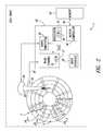
- FIG. 1is a schematic view generally illustrating an example disk drive, according to one illustrated embodiment.
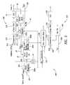
- FIG. 2is a schematic view illustrating in greater detail the example disk drive of FIG. 1 , according to one illustrated embodiment.
- FIG. 3is a schematic view illustrating an example disk for use in the disk drive of FIG. 1 , according to one illustrated embodiment.
- FIG. 4Ais a schematic view of servo fields in an example servo sector, according to one illustrated embodiment.
- FIG. 4Bis a schematic view of servo fields in a plurality of adjacent servo zones, according to one illustrated embodiment.
- FIG. 5is a schematic view of example circuitry for use in the disk drive of FIG. 1 , according to one illustrated embodiment.
- FIG. 6is a schematic view of example frequency multiplier/divider circuitry, according to one illustrated embodiment.
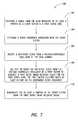
- FIG. 7is a flow chart illustrating one method of operating a disk drive, according to one illustrated embodiment.
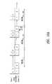
- FIG. 8includes three graphs showing example read channel samples taken at three different servo frequencies, according to one illustrated embodiment.
- FIG. 9Ais a basic flow chart illustrating changes made to a plurality of parameters when transitioning from a lower frequency servo zone to a higher frequency servo zone, according to one illustrated embodiment.
- FIG. 9Bis a basic flow chart illustrating changes made to a plurality of parameters when transitioning from a higher frequency servo zone to a lower frequency servo zone, according to one illustrated embodiment.
- FIG. 10Ais a schematic view of wedge-to-wedge timing changes when transitioning from a higher frequency servo zone to a lower frequency servo zone, according to one illustrated embodiment.
- FIG. 10Bis a schematic view of wedge-to-wedge timing changes when transitioning from a lower frequency servo zone to a higher frequency servo zone, according to one illustrated embodiment.
- disk drive 1comprises a disk 2 having a disk surface 4 including a plurality of servo zones 6 0-3 (delineated by the concentric circles of FIG. 1 ) of different servo frequencies, and a head 8 actuatable over the disk surface 4 , the head 8 operable to generate a signal indicative of at least a portion of a servo sector in a first servo zone (e.g., first servo zone 6 2 , although the head 8 may be operable to generate a signal indicative of any of the servo zones 6 ).
- a first servo zonee.g., first servo zone 6 2
- the disk drive 1may further include a frequency detector 10 operable to determine a servo frequency associated with the servo sector, and a read channel 12 coupled to the head 8 .
- the read channel 12further includes a voltage-controlled oscillator (“VCO”) 14 operable to provide a reference clock 16 , frequency multiplier/divider circuitry 18 operable to multiply or divide the reference clock 16 from the VCO 14 by a first factor to generate a first servo timing recovery clock 20 for the first servo zone 6 2 , the first factor based at least in part on the servo frequency determined by the frequency detector 10 , and a servo demodulator 22 operable to demodulate the at least a portion of the servo sector using the first servo timing recovery clock 20 .
- VCOvoltage-controlled oscillator
- the disk drive 1comprises a magnetic disk drive, and the methods described herein will be described in terms of such a disk drive. However, the methods, circuitry and devices described herein may also be applied to and/or implemented in other disk drives, including, e.g., optical and magneto-optical disk drives.
- the disk 2may comprise any of a variety of magnetic or optical disk media.
- the disk 2comprises conventional magnetic media having tracks defined in a servo writing process.
- the disk 2may comprise discrete track recording (“DTR”) media, having a plurality of concentric micro-grooves defined therein.
- the disk 2includes a disk surface 4 , as well as an opposite disk surface not visible in FIG. 1 .
- the disk surface 4comprises a plurality of generally concentric tracks defined at least in part by a plurality of servo sectors. These tracks may comprise data tracks for receiving and storing user data from a host computer in data sectors. In other embodiments, more disks may, of course, be included in the disk drive 1 , and different disk surfaces of these disks may be used for data storage.
- the disk surface 4may further include a plurality of servo zones 6 0-3 (collectively, 6 ) associated with different servo frequencies. These servo zones 6 may be better understood with reference to FIG. 3 , where the servo zones 6 have been enlarged to illustrate conceptually the different servo frequencies between the outside diameter of the disk 2 and the inside diameter. As illustrated, the servo frequencies generally increase from the inner diameter of the disk 2 to the outer diameter of the disk 2 . Thus, since the linear velocity of the disk 2 relative to the head 8 also increases towards the outer diameter of the disk 2 , each of the servo zones 6 0-3 may have roughly equivalent areal densities.
- the servo zones 6 0-3may be separated by logical servo zone boundaries 24 0-1 , 24 1-2 , and 24 2-3 (collectively, 24 ). Although these servo zone boundaries 24 are illustrated as visible lines in FIGS. 1 and 3 , there may, in fact, be no visible manifestation of these boundaries 24 .
- the servo zone boundaries 24may be aligned with corresponding data zone boundaries in a disk drive having a zoned data format. However, in other embodiments, the disk drive 1 may not include data zones. In still other embodiments, the servo zone boundaries 24 need not be aligned with data zone boundaries, and/or there may be more or less servo zones 6 than data zones.
- FIGS. 1 and 3four servo zones 6 0-3 are illustrated. However, in other embodiments, it may be understood that the disk surface 4 may be divided into any number of servo zones. As the number of servo zones increases, format efficiency increases, but there is increasing complexity associated with the greater number of servo zones. In one embodiment, between two and ten servo zones may be created on each disk surface 4 . In other embodiments, more than ten servo zones may be used.
- each servo zone 6may be associated with any of a variety of servo frequencies.
- f svo,0represents the servo frequency of the outermost servo zone 6 0
- f svo,irepresents the servo frequency of a corresponding servo zone 6 i
- L iis an integer that changes for each servo zone 6 i
- Kis kept constant.
- the disk surface 4may include four servo zones 6 0-3 , and the ratios between the servo frequencies of each of the servo zones 6 0-3 and the servo frequency of the outermost servo zone 6 0 may be equal to 4/4, 3/4, 2/4 and 1/4, respectively.
- L ivaries between 1 and 4, while the constant K is 4.
- the disk surfacemay include six servo zones.
- the servo frequenciesmay then be chosen such that the ratios between the servo frequencies of each of the servo zones and the servo frequency of the outermost servo zone are 16/16, 15/16, 12/16, 10/16, 8/16 and 6/16, from the outermost to the innermost servo zone, respectively.
- the servo frequency for the innermost zonemay be selected to be less than or equal to 50% of the servo frequency for the outermost zone.
- the servo frequency for the innermost zonemay be selected to be less than or equal to 37.5% of the servo frequency for the outermost zone.
- the servo frequencies of the servo zonesmay be selected such that each zone varies from the two adjacent servo zones by at least 10% of that servo zone's frequency. In yet another embodiment, the servo frequencies of the servo zones may be selected such that each zone varies from the two adjacent servo zones by at least 25% of that servo zone's frequency. In other embodiments, different servo frequencies and different numbers of servo zones may be used.
- each track on the disk surface 4is defined by a plurality of servo sectors, and that plurality of servo sectors is associated with one of the servo zones 6 .
- Each servo sectormay comprise a plurality of different servo fields, in order to facilitate, for example, seek operations and track following.
- One or more fields of the servo sectors in each servo zone 6may be recorded at the servo frequency associated with that servo zone 6 .
- a servo sector 400comprises a preamble 402 , a servo index mark/servo address mark (“SIM/SAM”) 404 , gray code and other servo fields 406 , and servo bursts 408 .
- the servo sector 400may be positioned adjacent user data 410 .
- the preamble 402may comprise a sequence of bits recorded at a constant frequency, and might include a sufficient number of consecutive flux reversals to enable circuitry in the read channel 12 to achieve phase synchronization with the preamble 402 .
- the preamble 402is recorded at the servo frequency associated with one of the servo zones 6 .
- the SIM/SAM 404may be used to synchronize servo sector timers for the subsequent detection of a servo sync mark (“SSM”), which may form part of the gray code and other servo fields 406 .
- SSMservo sync mark
- the SIM/SAM 404violates RLL code constraints, so that it is easily distinguished from all other information, and may be recorded at a frequency other than the servo frequency.
- the gray code and other servo fields 406might include a variety of servo information, including: a cylinder address/track identifier, a servo sector address, the SSM and cyclical redundancy check codes. One or more of these servo fields may be recorded redundantly in the servo sector 400 .
- the gray code and other servo fields 406may be recorded at the servo frequency associated with one of the servo zones 6 .
- the servo bursts 408may facilitate track following operations and enable the head 8 to closely track a hypothetical data track centerline.
- a number of servo sectorsmay be generally aligned radially to form servo wedges, as illustrated in FIGS. 1-3 . More or fewer servo wedges may be defined on the disk surface 4 in different embodiments.
- the servo sectorsare generally aligned radially such that a servo field located towards a middle of the servo sectors is in alignment.
- an SSM 26 of each servo sectormay be radially aligned, as illustrated by the line running radially through the servo zones 6 in FIG. 3 .
- the servo sectorsmay be generally aligned such that a servo field located towards a beginning of the servo sectors is in alignment.
- a beginning of the preamble of each servo sectormay be radially aligned.
- Any of the servo fields described abovemay be used to radially align the servo sectors.
- different alignmentsmay have corresponding ramifications for servo gate timing.
- tracks located near the servo zone boundaries 24may be mapped out for user data. That is, such tracks may not be used for data storage. By mapping out such tracks, the disk drive 1 may avoid track following near the servo zone boundaries 24 , and thus obviate any chattering between servo zones 6 . In one embodiment, between one and ten tracks to either side of a servo zone boundary 24 may be mapped out. In another embodiment, between ten and 50 tracks to either side of a servo zone boundary 24 may be mapped out.
- each servo zone 6may include multiple tracks at either end that include extended preambles.
- servo zone 6 1may include a set of servo sectors 400 a that include extended preambles 402 a as well as other servo fields 404 a - 408 a (as described at length above).
- the servo zone 6 1may also have another set of servo sectors 400 b closer to the inner diameter of the disk 2 that include extended preambles 402 b as well as other servo fields 404 b - 408 b . Between these servo sectors 400 a , 400 b , the servo zone 6 1 may include a plurality of servo sectors 400 having shorter preambles 402 .
- the servo sectors 400 a , 400 b with extended preambles 402 a , 402 bmay be associated with tracks that are mapped out. However, in other embodiments, user data may also be recorded on these tracks with extended preambles. Although three tracks with extended preambles are illustrated at each end of the servo zones 6 in FIG. 4B , more or fewer tracks may include extended preambles in different embodiments. In addition, although the extended preambles 402 a , 402 b are illustrated in an embodiment in which the servo sectors are aligned along respective servo sync marks (not shown in FIG.
- extended preamblesmay also be implemented in preamble-aligned or SAM-aligned servo formats.
- the servo zones 6 2 - 6 3may be formatted similarly to the servo zone 6 1 .
- the extended preambles 402 a , 402 bmay be formatted similarly to the preambles 402 found in the rest of the servo zone 6 1 , and they may simply include additional bits recorded at the corresponding frequency. In one embodiment, the extended preambles 402 a , 402 b may include at least 125% more bits than the other preambles 402 . In another embodiment, the preambles 402 a , 402 b may include at least 150% more bits than the other preambles 402 . These transition tracks with extended preambles may facilitate a faster, more certain transition between servo zones 6 .
- all of the servo sectors comprising the servo zones 6 0-3may be defined during a servo writing process. For example, in one embodiment, during a servo writing process, some servo sectors 400 are written with a first preamble length, and other servo sectors 400 a , 400 b are written with a second, extended preamble length. In other embodiments, all of the servo sectors may initially be written with extended preambles during the servo writing process. In a subsequent manufacturing act, those servo sectors 400 towards the middle of the servo zones 6 may have portions of their preambles 402 overwritten to define relatively shorter preambles 402 . Of course, in other embodiments, still other processes for defining shorter and longer preambles may be used.
- the servo writing processmay be performed in a variety of ways.
- an external servowritermay be used to define the servo sectors.
- a self-servo write (SSW) methodmay be employed.
- SSWself-servo write
- a magnetic printing process, discrete track recording, bit pattern media pattern process, or any other servo pattern proceduremay be used.
- the head 8is actuatable over the disk surface 4 and is operable to write to and read from the disk 2 .
- the head 8may be operable to generate a signal indicative of at least a portion of a servo sector in a first servo zone 6 2 .
- the head 8may read a portion of one or more servo fields of the servo sector, and generate signals indicative of such servo fields.
- the head 8includes a transducer (not illustrated).
- the transducermay include a writer and a read element.
- the transducer's writermay be of a longitudinal or perpendicular design, and the read element of the transducer may be inductive or magneto-resistive.
- the head 8may include an objective lens and an active or passive mechanism for controlling a separation of the objective lens from the disk surface 4 .
- the disk drive 1may further include a voice coil motor (“VCM”) 28 for rotating one or more actuator arms 30 about a pivot in order to actuate the head 8 at different positions over the disk surface 4 .
- VCMvoice coil motor
- other actuating mechanismsmay also be used to move the head 8 relative to the disk 2 .
- the disk drive 1further includes a frequency detector 10 operable to determine a servo frequency associated with the servo sector.
- the frequency detector 10may comprise any of a variety of firmware and/or hardware operable to determine the servo frequency. Although illustrated outside the read channel 12 in FIG. 1 , in one embodiment, the frequency detector 10 may comprise circuitry within the read channel 12 . In another embodiment, the frequency detector 10 may comprise firmware executed by a processor (not shown) of the disk drive 1 . In yet another embodiment, both read channel circuitry as well as firmware may comprise the frequency detector 10 .
- the frequency detector 10may determine the servo frequency associated with the servo sector in a variety of ways (as discussed at length below). In one embodiment, the frequency detector 10 may be configured to determine the servo frequency associated with the servo sector based upon a frequency of a preamble of the servo sector, or a preamble of another servo sector located within the first servo zone 6 2 . For example, in one embodiment, the frequency detector 10 may detect when the head 8 has crossed a servo zone boundary 24 between a second servo zone (e.g., 6 1 or 6 3 ) and the first servo zone 6 2 based on the characteristics of a preamble of a first servo sector associated with the first servo zone 6 2 .
- a second servo zonee.g., 6 1 or 6 3
- the frequency detector 10might then retrieve stored data indicative of the servo frequency associated with the first servo zone 6 2 and thereby determine the servo frequency associated with the servo sector.
- other fields associated with servo sectorsmay be processed by the frequency detector 10 in order to detect when the head 8 is positioned over the first servo zone 6 2 .
- the frequency detector 10may determine the servo frequency associated with the servo sector based upon the cylinder addresses/track identifiers previously read within a neighboring servo zone (e.g., 6 1 or 6 3 ). For example, in one embodiment, the frequency detector 10 may receive data indicative of a first previous track identifier associated with a second servo zone (e.g., 6 1 or 6 3 ). The frequency detector 10 may then determine that the head 8 is approaching a servo zone boundary 24 between the second servo zone and the first servo zone 6 2 based at least in part on the first previous track identifier.
- the frequency detector 10may determine that the head 8 is approaching the servo zone boundary 24 .
- the frequency detector 10may then retrieve data from memory in the disk drive 1 indicative of the servo frequency associated with the first servo zone 6 2 .
- the determination that the head 8 is approaching the servo zone boundary 24may also be based upon a seek velocity of the head 8 .
- the frequency detector 10may further improve the accuracy with which it predicts the time at which the head 8 will cross the servo zone boundary 24 into the first servo zone 6 2 by receiving data indicative of a second previous track identifier in the second servo zone after receiving the data indicative of the first previous track identifier.
- this second previous track identifiermay indicate that the head 8 is so close to the servo zone boundary 24 that the head 8 is predicted to cross the servo zone boundary 24 before a subsequent servo wedge passes underneath the head 8 .
- the frequency detector 10may thus predict that the head 8 will cross the servo zone boundary 24 into the first servo zone 6 2 , retrieve data indicative of the servo frequency associated with the first servo zone 6 2 , and thereby determine the servo frequency associated with the servo sector.
- the disk drive 1may further include a read channel 12 .
- a preamplifier(not shown in FIG. 1 ) may amplify an analog signal detected by the head 8 in order to achieve a signal level that can be processed by the read channel 12 .
- the read channel 12may then receive the amplified signal and further amplify, filter and convert the analog pulses into digital data that is output to a controller (also not shown in FIG. 1 ).
- the read channel 12may receive digital data from the controller and forward logical signals representative of this digital data to the preamplifier for recording via the head 8 .
- the read channel 12includes at least one VCO 14 operable to provide a reference clock 16 .
- the VCO 14may comprise one component of a phase-locked loop (described in greater detail with reference to FIG. 5 ) that may generate one or more frequencies for demodulating portions of the servo sector and/or for timing other disk drive clocks.
- the VCO 14may be operable to provide a reference clock 16 that stays relatively constant over the range of servo frequencies associated with the different servo zones 6 0-3 .
- the VCO 14is illustrated as coupled to the head 8 in FIG. 1 , it may be understood that a signal from the head 8 may be processed and modified by a variety of components before some derivative thereof reaches the VCO 14 (as described in greater detail with reference to FIG. 5 ).
- the read channel 12further includes frequency multiplier/divider circuitry 18 coupled to the VCO 14 and operable to multiply or divide the reference clock 16 from the VCO 14 by a first factor to generate a first servo timing recovery clock 20 .
- the frequency multiplier/divider circuitry 18may comprise any of a variety of digital and/or analog circuitry configured to multiply and/or divide the reference clock 16 in order to generate the first servo timing recovery clock 20 .
- the frequency multiplier/divider circuitry 18may include one or more multiplier circuits, and one or more divider circuits in series or in parallel.
- the first servo timing recovery clock 20may have a frequency substantially equal to the servo frequency associated with the servo sector.
- the frequency multiplier/divider circuitry 18may be configured to multiply or divide the reference clock 16 by a number of selectable factors. For example, the frequency multiplier/divider circuitry 18 may be configured to multiply or divide the reference clock 16 by a first factor based at least in part on the servo frequency determined by the frequency detector 10 . In one embodiment, if a different servo frequency is determined by the frequency detector 10 , the frequency multiplier/divider circuitry 18 may be configured to multiply or divide the reference clock 16 by a second factor to generate a different servo timing recovery clock 20 . Thus, different servo timing recovery clocks 20 may be generated by the frequency multiplier/divider circuitry 18 depending upon the particular factor applied to the reference clock 16 . In some embodiments, each of the servo timing recovery clocks 20 has a frequency equal to a servo frequency associated with a corresponding servo zone 6 .
- the frequency multiplier/divider circuitry 18may include at least one rewritable register (not shown in FIG. 1 ) configured to receive at least one variable used to multiply or divide the reference clock 16 .
- the frequency detector 10may write to the rewritable register in order to change the factor applied by the frequency multiplier/divider circuitry 18 when generating the first servo timing recovery clock 20 .
- the frequency detector 10may thus relatively quickly change the servo timing recovery clock 20 based at least in part on the servo frequency.
- the frequency multiplier/divider circuitry 18may include a plurality of multiplier/divider circuits associated with different factors and configured to generate different servo timing recovery clocks 20 .
- the frequency multiplier/divider circuitry 18may further include a switch configured to select among the plurality of multiplier/divider circuits, and the frequency detector 10 may be configured to control the switch in order to change the factor applied by the frequency multiplier/divider circuitry 18 .
- other structures/circuitrymay be employed to enable the frequency detector 10 to modify the factor applied by the frequency multiplier/divider circuitry 18 .
- the frequency multiplier/divider circuitry 18may be incorporated into a phase-locked loop with the VCO 14 .
- the factor applied by the frequency multiplier/divider circuitry 18may be changed in order to generate a new servo timing recovery clock 20 corresponding to the servo frequency of the new servo zone 6 .
- the VCO 14may maintain a substantially constant reference clock 16 , and therefore the time required to synchronize with the new servo zone 6 may be lessened due to the relatively immediate clock change executed in the frequency multiplier/divider circuitry 18 .
- the frequency multiplier/divider circuitry 18 and the frequency detector 10may enable a switch to the new servo timing recovery clock 20 with a maximum of one servo wedge latency. In some embodiments, there may be zero servo wedge latency before the correct servo timing recovery clock is enabling servo demodulation.
- the read channel 12further includes a servo demodulator 22 operable to demodulate the at least a portion of the servo sector using the first servo timing recovery clock 20 .
- the servo demodulator 22is coupled (directly or indirectly) to the frequency multiplier/divider circuitry 18 , and is further coupled (directly or indirectly) to the head 8 in order to receive a signal therefrom. Any of a variety of servo demodulation circuitry may be used in the servo demodulator 22 in order to derive servo information from different fields comprising the servo sector.
- the servo demodulator 22may employ the first servo timing recovery clock 20 in its demodulation process. In one embodiment, for example, the first servo timing recovery clock 20 may be used by the servo demodulator 22 to determine a sampling rate for processing the servo sector.
- FIG. 2additional circuitry for controlling various functions of the disk drive 1 is illustrated in greater detail. However, in other embodiments, at least some of the illustrated circuitry may be omitted.
- the read channel 12may be coupled to the head 8 via a preamplifier 32 and a plurality of read and write lines 34 .
- the preamplifier 32may be located on the actuator 30 within the disk drive 1 , or at a variety of other locations.
- the disk drive 1may further comprise a servo subsystem 36 .
- the servo subsystem 36receives a position signal via the preamplifier 32 and the read channel 12 and performs calculations to determine a current position of the head 8 over the disk 2 . The servo subsystem 36 may then use these calculations in order to control the VCM 28 , and thereby control the position of the head 8 .
- Disk drive 1may further include a disk drive host interface 38 that mediates communication with a host computer (not shown).
- the disk drive host interface 38receives commands and data from and transmits status and data to the host computer.
- the disk drive host interface 38may comply with any of a number of technical standards.
- the disk drive host interface 38may include a serial interface, such as a Serial Advanced Technology Attachment (“SATA”) interface or a Serial Attached Small Computer System Interface (“SAS”).
- SASSerial Attached Small Computer System Interface
- a parallel interfacemay be used, such as an Advanced Technology Attachment/Integrated Drive Electronics (“ATA/IDE”) interface or a Small Computer System Interface (“SCSI”).
- Disk drive 1may further include a processor 40 configured to execute one or more instructions in order to control certain operations performed by the disk drive 1 .
- the processor 40may comprise part of a controller and may be configured to execute computer-readable instructions stored on computer-readable memory 42 , which is communicatively coupled thereto by at least one data line 44 .
- the memory 42may comprise any type of volatile or non-volatile computer-readable memory, such as dynamic random access memory (DRAM) or flash memory. As illustrated, the memory 42 comprises a memory module separate and distinct from the disk 2 . However, in other embodiments, various instructions executable by the processor 40 may be stored on the disk 2 .
- DRAMdynamic random access memory
- flash memoryany type of volatile or non-volatile computer-readable memory, such as dynamic random access memory (DRAM) or flash memory.
- DRAMdynamic random access memory
- flash memoryAs illustrated, the memory 42 comprises a memory module separate and distinct from the disk 2 . However, in other embodiments, various instructions executable by the processor 40 may be stored on the disk 2 .
- the disk drive 1may further comprise a buffer controller 46 directly coupled to the memory 42 .
- the buffer controller 46arbitrates access to the memory 42 by other circuit components.
- the memory 42may include firmware and other computer-readable instructions executable by the processor 40 .
- SoCsystem on a chip
- PCBprinted circuit board
- the frequency detector 10may be located in the read channel 12 in a hardware implementation, and/or in the processor 40 /memory 42 as a firmware implementation.
- the computer-readable memory 42may have instructions stored thereon that are executable by the processor 40 in order to cause the processor 40 to determine the servo frequency associated with the servo sector in a variety of ways, as described in greater detail below.
- both hardware and firmwaremay be used in order to determine the servo frequencies associated with different servo sectors and corresponding servo zones 6 .
- FIG. 5illustrates in greater detail circuitry and/or firmware 500 both within and external to the read channel 12 .
- the illustrated circuitryrepresents just one example embodiment.
- a servo signal 502is received by the circuitry 500 .
- the servo signal 502may be generated by the head 8 and may represent at least a portion of a preamble of a servo sector.
- the servo signal 502may first be filtered/processed by one or more filters 504 .
- the filters 504may comprise one or more analog and/or digital filters configured to receive and filter/process the servo signal 502 .
- the filters 504may include, inter alia, a continuous time filter (“CTF”), a finite impulse response filter (“FIR”), and a magnetic resistive asymmetry (“MRA”) linearizer.
- CTFcontinuous time filter
- FIRfinite impulse response filter
- MRAmagnetic resistive asymmetry
- additional and/or different filtersmay be arranged to receive the servo signal 502 .
- the filters 504may be associated with one or more settings that may be optimized in order to effectively filter the servo signal 502 at different servo frequencies. For example, settings for the CTF, FIR and MRA linearizer may be varied at different servo frequencies in order to optimally filter/process the signal for subsequent demodulation. As illustrated, the filters 504 may thus be associated with one or more registers 504 a configured to receive and store settings for different servo frequencies. In one embodiment, as described at greater length below, the settings stored in such registers 504 a may be adjusted by the frequency detector 10 based at least in part on a servo frequency associated with the first servo zone 6 2 .
- a number of settings for the filters 504 amay be stored in the memory 42 or on the disk 2 and may be associated with different servo frequencies.
- these settingsmay be accessed by the frequency detector 10 , and the registers 504 a may be programmed with the new settings.
- different circuitryconfigured to change the settings associated with the filters 504 may be used.
- the filtered servo signal 506may be routed from the filters 504 to a variety of different circuitry.
- the filtered servo signal 506is transmitted to the servo demodulator 22 , and, as illustrated, the servo demodulator 22 may demodulate and extract information indicative of the gray code and other fields 506 a , servo bursts 506 b and SIM/SAM 506 c from the filtered servo signal 506 .
- the filtered servo signal 506may also be transmitted to the frequency detector 10 , whether implemented in firmware and/or hardware. For example, the filtered servo signal 506 may be forwarded to hardware within the read channel 12 . In another embodiment, the filtered servo signal 506 or another signal derived from the filtered servo signal 506 may be transmitted to the processor 40 .
- the filtered servo signal 506may also be transmitted to a first phase-locked loop (“PLL”) 508 .
- the filtered servo signal 506(indicative of a preamble of a servo sector) may be routed to a comparator 510 of the PLL 508 , which may then compare the filtered servo signal 506 against a frequency 512 generated by the frequency multiplier/divider circuitry 18 .
- the PLL 508may be initialized using a crystal clock 514 . However, after initialization, the PLL 508 may be configured to lock onto and generate a servo timing recovery clock 20 based upon the filtered servo signal 506 .
- the PLL 508may comprise the comparator 510 , a loop filter 516 , the VCO 14 , and the frequency multiplier/divider circuitry 18 .
- the frequency multiplier/divider circuitry 18comprises a first divider 518 coupled to the VCO 14 and configured to divide the reference clock 16 from the VCO 14 to generate a substantially constant clock 520 .
- the substantially constant clock 520may then be used to time a variety of operations in the disk drive 1 .
- the substantially constant clock 520may be received by additional multiplier/divider circuitry 522 configured to multiply or divide the substantially constant clock 520 in order to generate the first servo timing recovery clock 20 .
- This servo timing recovery clock 20may then be used (as illustrated) by the servo demodulator 22 in order to demodulate the filtered servo signal 506 .
- the additional multiplier/divider circuitry 522may include at least one rewritable register 522 a configured to receive at least one variable used to multiply or divide the reference clock 16 from the VCO 14 to generate the first servo timing recovery clock 20 .
- the frequency detector 10may be coupled to the register 522 a , and the variable stored in this register 522 a may be adjusted by the frequency detector 10 based at least in part on a servo frequency associated with the first servo zone 6 2 . For example, a number of variables may be stored in the memory 42 or on the disk 2 and may be associated with different servo frequencies.
- these variablesmay be accessed by the frequency detector 10 , and the register 522 a may be programmed with a new variable corresponding to the first servo zone 6 2 .
- other structures for changing the effective factor associated with the frequency multiplier/divider circuitry 18may also be used.
- a non-digital implementationmay be used in order to adjust the effective factor.
- the frequency multiplier/divider circuitry 18may comprise a plurality of multiplier/divider circuits 602 a - c coupled to a switch 604 .
- Each of the multiplier/divider circuits 602 a - cmay be associated with different factors and may be configured to generate different servo timing recovery clocks.
- the switch 604(which may be controlled by the frequency detector 10 ) may therefore be configured to select among the plurality of multiplier/divider circuits 602 a - c depending upon the current servo zone 6 .
- the frequency detector 10is communicatively coupled to the frequency multiplier/divider circuitry 18 , to the filters 502 , and to wedge-to-wedge timing adjustment circuitry 524 .
- the frequency detector 10may thus send to these different circuit components one or more signals related to the servo frequency associated with the servo sector 8 . These signals may be configured to change one or more operating variables associated with each of these circuit components.
- the wedge-to-wedge timing adjustment circuitry 524may be configured to adjust the wedge-to-wedge timing between adjacent servo wedges when the head 8 is crossing over a servo zone boundary 24 (as described in greater detail below with reference to FIGS. 10A and 10B ). As illustrated, the wedge-to-wedge timing adjustment circuitry 524 may output a signal that comprises one input to the disk locked clock 526 , which may be used to time a servo gate for reading servo wedges.
- the other input of the disk locked clock 526may originate from a second phase-locked loop 532 .
- the PLL 532may comprise a comparator 534 , a loop filter 536 , a VCO 538 and multiplier/divider circuitry 540 .
- a clock signal 542 from a crystal oscillatormay comprise the input to the PLL 532 , and the output clock signal 544 may be configured to time the disk locked clock 526 , adjusted as necessary by detection of the SIM/SAM and the wedge-to-wedge timing adjustment circuitry 524 .
- FIG. 7illustrates a flow diagram for a method 700 of operating a disk drive, according to one embodiment.
- the method 700will be discussed in the context of the disk drive 1 of FIGS. 1-5 with reference to FIGS. 8-10B .
- the acts disclosed hereinmay be executed in a variety of different disk drives or other storage devices, in accordance with the described method.
- a signal 502 from the head 8 indicative of at least a portion of a servo sector in a first servo zone 6 2is received.
- the signal 502 from the head 8is received at the read channel 12 via the preamplifier 32 .
- the signal 502may be amplified, conditioned, filtered or otherwise modified before receipt.
- the servo sectormay comprise a number of different servo fields, and the signal 502 may be indicative of any portion of one or more of those servo fields. In one embodiment, the signal 502 may be indicative of at least a portion of a preamble of the servo sector.
- the first servo zone 6 2may be associated with any of a variety of servo frequencies. In one embodiment, the first servo zone 6 2 may have a servo frequency that is greater than that of servo zone 6 3 and less than that of servo zone 6 1 .
- a servo frequency associated with the servo sectoris determined.
- the servo frequency associated with the servo sectormay be determined in any of a variety of ways, as discussed above.
- a frequency detector 10(implemented in firmware and/or hardware) may be used to determine the servo frequency associated with the servo sector.
- determining the servo frequencymay comprise executing instructions in a processor 40 of the disk drive 1 .
- the processor 40may determine a servo frequency associated with the first servo zone 6 2 in order to determine the servo frequency associated with the servo sector. For example, the processor 40 may determine the servo frequency of a new servo zone each time a servo zone boundary is crossed, and it may then be assumed that the same servo frequency will be used throughout the servo zone in each servo sector. Determining the servo frequency may thus include receiving data indicative of a first previous track identifier associated with a second servo zone (e.g., servo zone 6 1 or 6 3 ).
- a servo zone boundarye.g., servo zone boundary 24 1-2 or 24 2-3
- data indicative of the servo frequency associated with the first servo zone 6 2may be retrieved.
- data indicative of the servo frequencies of all of the servo zones 6 0-3may be stored in the memory 42 , and may be retrieved as the head 8 approaches a servo zone boundary.
- the processor 40may further receive data indicative of a seek velocity of the head 8 , and it may be determined that the head 8 is approaching the servo zone boundary based at least in part on the seek velocity.
- the seek velocitymay be taken into account in predicting a servo zone boundary crossing.
- other factorsmay be taken into account in predicting a servo zone boundary crossing. For example, an acceleration of the head 8 may be taken into account, which may be determined based upon a control signal applied to the VCM 28 , as well as a flex cable bias force.
- the head 8may be approaching the first servo zone 6 2 from a servo zone of higher or lower frequency. Assuming that the head 8 is approaching the first servo zone 6 2 from a second servo zone 6 3 having a lower frequency, one example flow chart illustrating changes made to a plurality of parameters when transitioning from the second servo zone 6 3 to the first servo zone 6 2 is illustrated in FIG. 9A .
- the read channel 12may be placed in a switching state, wherein a setting for at least one analog filter (e.g., at least one of the filters 502 ) between the head 8 and the servo demodulator 22 is calibrated to the first servo zone 6 2 , and the reference clock 16 from the VCO 14 is multiplied or divided by a second factor different than a first factor to generate a second servo timing recovery clock 20 based at least in part on a second servo frequency associated with the second servo zone 6 3 . That is, some filtering and/or signal conditioning settings may be changed before the servo timing recovery clock 20 is adjusted. As illustrated in FIG.
- CTF, FIR and MRA linearizer settingsmay be changed before the variables, M and N, used to change the factor applied by the frequency multiplier/divider circuitry 18 .
- This processmay ready the read channel 12 to efficiently and effectively filter servo sectors in the first servo zone 6 2 before the head 8 has crossed the servo zone boundary 24 2-3 . In one embodiment, this may facilitate the process of synchronization once the head 8 has crossed the servo zone boundary 24 2-3 .
- the filter settings applied at the read channel 12may be maintained, and the variables for the frequency multiplier/divider circuitry 18 may be adjusted for the servo frequency of the first servo zone 6 2 .
- two sets of registers in the filters 504 and in the frequency multiplier/divider circuitry 18may be used in order to implement the switching state.
- one set of “switching state” registers in the filters 504may be programmed as illustrated in FIG. 9A , and the filters 504 may apply the settings in those “switching state” registers.
- a set of “permanent” registers in the filters 504may be programmed as illustrated in FIG. 9A , and the filters 504 may apply the settings in those “permanent” registers.
- Similar registersmay be used in the frequency multiplier/divider circuitry 18 . In some embodiments, these registers may be pre-programmed with upcoming servo zone settings/variables in order to make the switching process even faster.
- FIG. 9Bone example flow chart illustrating changes made to a plurality of parameters when transitioning from the second servo zone 6 1 to the first servo zone 6 2 is illustrated in FIG. 9B .
- the read channel 12may not be placed in a switching state before crossing the servo zone boundary 24 1-2 because the filter settings used for the higher frequency second servo zone 6 1 may work relatively well for the lower frequency first servo zone 6 2 as well.
- the read channel 12may enter a switching state, wherein a setting for at least one analog filter (e.g., at least one of the filters 502 ) between the head 8 and the servo demodulator 22 is calibrated to the second servo zone 6 1 , but the reference clock 16 from the VCO 14 is multiplied or divided by the first factor to generate the first servo timing recovery clock 20 associated with the first servo zone 6 2 . That is, the servo timing recovery clock 20 may be changed before some filtering and/or signal conditioning settings are adjusted. As illustrated in FIG.
- the variables, M and N, used to change the factor applied by the frequency multiplier/divider circuitry 18may be changed before the CTF, FIR and MRA linearizer settings. In one embodiment, this may facilitate the process of synchronization once the head 8 has crossed the servo zone boundary 24 1-2 . As illustrated in FIG. 9B , after the head 8 has crossed the servo zone boundary 24 1-2 , the filter settings applied at the read channel 12 may be changed, and the variables for the frequency multiplier/divider circuitry 18 may be maintained.
- the processor 40may be further configured to receive data indicative of a second previous track identifier associated with the second servo zone (e.g., servo zone 6 1 or 6 3 ), the data indicative of the second previous track identifier received after the data indicative of the first previous track identifier. It may then be predicted based at least in part on the second previous track identifier that the head 8 will cross the servo zone boundary before a subsequent servo wedge passes underneath the head 8 . Thus, in one embodiment, the processor 40 may first determine that a servo zone boundary is approaching, and may then determine that the head 8 will cross the servo zone boundary before another servo wedge.
- a second previous track identifierassociated with the second servo zone
- the processor 40may first determine that a servo zone boundary is approaching, and may then determine that the head 8 will cross the servo zone boundary before another servo wedge.
- the first previous track identifiermay be indicative of a track 50 tracks away from the servo zone boundary
- the second previous track identifiermay be indicative of a track just two tracks away from the servo zone boundary.
- determinations and predictionsmay be dependent upon a seek velocity of the head 8 .
- the reference clock 16 from the VCO 14is then multiplied or divided to generate the first servo timing recovery clock 20 based at least in part on the prediction that the head 8 will cross the servo zone boundary and on the servo frequency associated with the first servo zone 6 2 .
- the servo frequencymay be determined using circuitry/hardware within the read channel 12 .
- determining the servo frequencymay include detecting when the head 8 has crossed a servo zone boundary between a second servo zone and the first servo zone 6 2 based on characteristics of a preamble of a first servo sector associated with the first servo zone 6 2 .
- the characteristics of the preamblemay be quantified by sampling the preamble signal.
- the three graphs 800 a - cshow three example preamble waveforms and corresponding samples taken therefrom.
- Different servo frequenciesmay yield very different samples, and different characteristics of these samples may be used to quickly and accurately detect that the head 8 has crossed a servo zone boundary.
- different characteristics of the preamblemay be evaluated to detect when the head 8 has crossed a servo zone boundary. For example, a Discrete Fourier Transform (“DFT”) or sampling pattern matching may be used to detect a servo zone boundary crossing.
- DFTDiscrete Fourier Transform
- sampling pattern matchingmay be used to detect a servo zone boundary crossing.
- the head 8before detecting when the head 8 has crossed the servo zone boundary, it may be predicted that the head 8 will cross the servo zone boundary may be made by executing instructions in a processor 40 of the disk drive 1 , as described at length above. In other embodiments, the above-described and other forms of hardware and firmware detection may be combined.
- a reference clock 16 from the VCO 14 of the read channel 12is received.
- the reference clock 16may remain substantially constant throughout the different servo zones 6 0-3 and their associated servo frequencies.
- the reference clock 16 from the VCO 14is multiplied or divided by a first factor to generate a first servo timing recovery clock 20 for the first servo zone 6 2 , the first factor selected based at least in part on the determined servo frequency.
- the reference clock 16may be multiplied or divided (as used in this phrase, it may be understood to mean and/or) by frequency multiplier/divider circuitry 18 to generate the first servo timing recovery clock 20 .
- the first factormay be selected based at least in part on the determined servo frequency, such that the first servo timing recovery clock 20 is configured to be in phase with and at a same frequency as the servo frequency associated with the servo sector.
- multiplying or dividing the reference clock 16 from the VCO 14may include setting at least one rewritable register 522 a with at least one variable used to multiply or divide the reference clock 16 from the VCO 14 to generate the first servo timing recovery clock 20 .
- multiplying or dividing the reference clock 16 from the VCO 14may include switching between a plurality of multiplier/divider circuits 602 a - c associated with different factors and configured to generate different servo timing recovery clocks 20 .
- multiplying or dividing the reference clock 16may include dividing the reference clock 16 to generate a substantially constant clock 520 , and multiplying or dividing the substantially constant clock 520 to generate the first servo timing recovery clock 20 .
- the at least a portion of the servo sectormay be demodulated using the first servo timing recovery clock 20 .
- any of a variety of demodulation algorithmsmay be applied in order to extract servo information from the servo sector based at least in part on the first servo timing recovery clock 20 .
- the disk drive 1may use settings and variables associated with one of the servo zones 6 . If the PLL 508 is unable to effectively synchronize with the servo sectors passing underneath the head 8 using those settings and variables, the settings and variables associated with another of the servo zones 6 may be used, until the disk drive 1 has correctly identified the current servo zone 6 .
- FIGS. 10A and 10Bthe wedge-to-wedge timing may change.
- a wedge-to-wedge timing between adjacent servo wedges in one servo zonemay be represented by W2W i,j , wherein i represents the ith servo zone and j represents the jth servo wedge.
- a wedge-to-wedge timing adjustment variable W i,j,j+1may be used to account for the difference in wedge-to-wedge timing between the two servo zones.
- This wedge-to-wedge timing adjustment variable W i,j,j+1may be based at least in part on the servo zone boundary crossing, as well as on the servo wedge at which the head 8 crossed, and may be used once to transition from one servo zone 6 to the next.
- the appropriate wedge-to-wedge timing for that servo zone 6may be applied.
- a very similar wedge-to-wedge timing adjustmentis illustrated in FIG. 10B , as the head 8 moves from a servo zone 6 of lower frequency to a servo zone 6 of higher frequency.
- the wedge-to-wedge timing adjustmentmay be implemented in a variety of ways.
- the frequency detector 10may be coupled to wedge-to-wedge timing adjustment circuitry 524 , and, upon determining that the head 8 will cross or has already crossed a servo zone boundary 24 , the frequency detector 10 may send a signal to the wedge-to-wedge timing adjustment circuitry 524 causing it to make an appropriate adjustment.
- other circuitry and/or firmware implementationsmay be used.
Landscapes
- Engineering & Computer Science (AREA)
- Signal Processing (AREA)
- Moving Of The Head To Find And Align With The Track (AREA)
Abstract
Description
fsvo,i=(Li/K)fsvo,0 Equation 1
Claims (33)
Priority Applications (1)
| Application Number | Priority Date | Filing Date | Title |
|---|---|---|---|
| US12/401,494US8213106B1 (en) | 2009-03-10 | 2009-03-10 | Zoned servo system |
Applications Claiming Priority (1)
| Application Number | Priority Date | Filing Date | Title |
|---|---|---|---|
| US12/401,494US8213106B1 (en) | 2009-03-10 | 2009-03-10 | Zoned servo system |
Publications (1)
| Publication Number | Publication Date |
|---|---|
| US8213106B1true US8213106B1 (en) | 2012-07-03 |
Family
ID=46320190
Family Applications (1)
| Application Number | Title | Priority Date | Filing Date |
|---|---|---|---|
| US12/401,494Active2029-10-30US8213106B1 (en) | 2009-03-10 | 2009-03-10 | Zoned servo system |
Country Status (1)
| Country | Link |
|---|---|
| US (1) | US8213106B1 (en) |
Cited By (115)
| Publication number | Priority date | Publication date | Assignee | Title |
|---|---|---|---|---|
| US20130077188A1 (en)* | 2011-09-23 | 2013-03-28 | Lsi Corporation | Systems and Methods for Controlled Wedge Spacing in a Storage Device |
| US8576506B1 (en) | 2012-06-21 | 2013-11-05 | Western Digital Technologies, Inc. | Disk drive estimating reader/writer gap across servo zones |
| US8625216B2 (en)* | 2012-06-07 | 2014-01-07 | Lsi Corporation | Servo zone detector |
| US8724245B1 (en) | 2012-06-21 | 2014-05-13 | Western Digital Technologies, Inc. | Disk drive employing overlapping servo zones to facilitate servo zone crossing |
| US8743504B1 (en) | 2012-07-25 | 2014-06-03 | Western Digital Technologies, Inc. | Servoing on zoned concentric servo sectors of a first disk surface to write a spiral servo track to a second disk surface |
| US8780477B1 (en) | 2012-06-21 | 2014-07-15 | Western Digital Technologies, Inc. | Disk drive adjusting servo timing to compensate for transient when crossing a servo zone boundary |
| US8824081B1 (en) | 2012-03-13 | 2014-09-02 | Western Digital Technologies, Inc. | Disk drive employing radially coherent reference pattern for servo burst demodulation and fly height measurement |
| US8830617B1 (en) | 2013-05-30 | 2014-09-09 | Western Digital Technologies, Inc. | Disk drive adjusting state estimator to compensate for unreliable servo data |
| US8879191B1 (en) | 2012-11-14 | 2014-11-04 | Western Digital Technologies, Inc. | Disk drive modifying rotational position optimization algorithm to achieve target performance for limited stroke |
| US8891194B1 (en) | 2013-05-14 | 2014-11-18 | Western Digital Technologies, Inc. | Disk drive iteratively adapting correction value that compensates for non-linearity of head |
| US8891191B1 (en) | 2014-05-06 | 2014-11-18 | Western Digital Technologies, Inc. | Data storage device initializing read signal gain to detect servo seed pattern |
| US8896957B1 (en) | 2013-05-10 | 2014-11-25 | Western Digital Technologies, Inc. | Disk drive performing spiral scan of disk surface to detect residual data |
| US8902539B1 (en) | 2014-05-13 | 2014-12-02 | Western Digital Technologies, Inc. | Data storage device reducing seek power consumption |
| US8902538B1 (en) | 2013-03-29 | 2014-12-02 | Western Digital Technologies, Inc. | Disk drive detecting crack in microactuator |
| US8913342B1 (en) | 2014-03-21 | 2014-12-16 | Western Digital Technologies, Inc. | Data storage device adjusting range of microactuator digital-to-analog converter based on operating temperature |
| US8917475B1 (en) | 2013-12-20 | 2014-12-23 | Western Digital Technologies, Inc. | Disk drive generating a disk locked clock using radial dependent timing feed-forward compensation |
| US8917474B1 (en) | 2011-08-08 | 2014-12-23 | Western Digital Technologies, Inc. | Disk drive calibrating a velocity profile prior to writing a spiral track |
| US8922938B1 (en) | 2012-11-02 | 2014-12-30 | Western Digital Technologies, Inc. | Disk drive filtering disturbance signal and error signal for adaptive feed-forward compensation |
| US8922937B1 (en) | 2012-04-19 | 2014-12-30 | Western Digital Technologies, Inc. | Disk drive evaluating multiple vibration sensor outputs to enable write-protection |
| US8922931B1 (en) | 2013-05-13 | 2014-12-30 | Western Digital Technologies, Inc. | Disk drive releasing variable amount of buffered write data based on sliding window of predicted servo quality |
| US8922940B1 (en) | 2014-05-27 | 2014-12-30 | Western Digital Technologies, Inc. | Data storage device reducing spindle motor voltage boost during power failure |
| US8929021B1 (en) | 2012-03-27 | 2015-01-06 | Western Digital Technologies, Inc. | Disk drive servo writing from spiral tracks using radial dependent timing feed-forward compensation |
| US8929022B1 (en) | 2012-12-19 | 2015-01-06 | Western Digital Technologies, Inc. | Disk drive detecting microactuator degradation by evaluating frequency component of servo signal |
| US8934186B1 (en) | 2014-03-26 | 2015-01-13 | Western Digital Technologies, Inc. | Data storage device estimating servo zone to reduce size of track address |
| US8937784B1 (en) | 2012-08-01 | 2015-01-20 | Western Digital Technologies, Inc. | Disk drive employing feed-forward compensation and phase shift compensation during seek settling |
| US8941945B1 (en) | 2014-06-06 | 2015-01-27 | Western Digital Technologies, Inc. | Data storage device servoing heads based on virtual servo tracks |
| US8941939B1 (en) | 2013-10-24 | 2015-01-27 | Western Digital Technologies, Inc. | Disk drive using VCM BEMF feed-forward compensation to write servo data to a disk |
| US8947819B1 (en) | 2012-08-28 | 2015-02-03 | Western Digital Technologies, Inc. | Disk drive implementing hysteresis for primary shock detector based on a more sensitive secondary shock detector |
| US8953271B1 (en) | 2013-05-13 | 2015-02-10 | Western Digital Technologies, Inc. | Disk drive compensating for repeatable run out selectively per zone |
| US8953278B1 (en) | 2011-11-16 | 2015-02-10 | Western Digital Technologies, Inc. | Disk drive selecting disturbance signal for feed-forward compensation |
| US8958169B1 (en) | 2014-06-11 | 2015-02-17 | Western Digital Technologies, Inc. | Data storage device re-qualifying state estimator while decelerating head |
| US8970979B1 (en) | 2013-12-18 | 2015-03-03 | Western Digital Technologies, Inc. | Disk drive determining frequency response of actuator near servo sample frequency |
| US8976475B1 (en) | 2013-11-12 | 2015-03-10 | Lsi Corporation | Systems and methods for large sector dynamic format insertion |
| US8982501B1 (en) | 2014-09-22 | 2015-03-17 | Western Digital Technologies, Inc. | Data storage device compensating for repeatable disturbance when commutating a spindle motor |
| US8982490B1 (en) | 2014-04-24 | 2015-03-17 | Western Digital Technologies, Inc. | Data storage device reading first spiral track while simultaneously writing second spiral track |
| US8995075B1 (en) | 2012-06-21 | 2015-03-31 | Western Digital Technologies, Inc. | Disk drive adjusting estimated servo state to compensate for transient when crossing a servo zone boundary |
| US8995082B1 (en) | 2011-06-03 | 2015-03-31 | Western Digital Technologies, Inc. | Reducing acoustic noise in a disk drive when exiting idle mode |
| US9001454B1 (en) | 2013-04-12 | 2015-04-07 | Western Digital Technologies, Inc. | Disk drive adjusting phase of adaptive feed-forward controller when reconfiguring servo loop |
| US9007714B1 (en) | 2014-07-18 | 2015-04-14 | Western Digital Technologies Inc. | Data storage device comprising slew rate anti-windup compensation for microactuator |
| US9013825B1 (en) | 2014-03-24 | 2015-04-21 | Western Digital Technologies, Inc. | Electronic system with vibration management mechanism and method of operation thereof |
| US9013824B1 (en) | 2014-06-04 | 2015-04-21 | Western Digital Technologies, Inc. | Data storage device comprising dual read sensors and dual servo channels to improve servo demodulation |
| US9025269B1 (en) | 2014-01-02 | 2015-05-05 | Western Digital Technologies, Inc. | Disk drive compensating for cycle slip of disk locked clock when reading mini-wedge |
| US9026728B1 (en) | 2013-06-06 | 2015-05-05 | Western Digital Technologies, Inc. | Disk drive applying feed-forward compensation when writing consecutive data tracks |
| US9047932B1 (en) | 2014-03-21 | 2015-06-02 | Western Digital Technologies, Inc. | Data storage device adjusting a power loss threshold based on samples of supply voltage |
| US9047901B1 (en) | 2013-05-28 | 2015-06-02 | Western Digital Technologies, Inc. | Disk drive measuring spiral track error by measuring a slope of a spiral track across a disk radius |
| US9047919B1 (en) | 2013-03-12 | 2015-06-02 | Western Digitial Technologies, Inc. | Disk drive initializing servo read channel by reading data preceding servo preamble during access operation |
| US9053726B1 (en) | 2014-01-29 | 2015-06-09 | Western Digital Technologies, Inc. | Data storage device on-line adapting disturbance observer filter |
| US9053712B1 (en) | 2014-05-07 | 2015-06-09 | Western Digital Technologies, Inc. | Data storage device reading servo sector while writing data sector |
| US9053727B1 (en) | 2014-06-02 | 2015-06-09 | Western Digital Technologies, Inc. | Disk drive opening spiral crossing window based on DC and AC spiral track error |
| US9058826B1 (en) | 2014-02-13 | 2015-06-16 | Western Digital Technologies, Inc. | Data storage device detecting free fall condition from disk speed variations |
| US9058827B1 (en) | 2013-06-25 | 2015-06-16 | Western Digitial Technologies, Inc. | Disk drive optimizing filters based on sensor signal and disturbance signal for adaptive feed-forward compensation |
| US9058834B1 (en) | 2013-11-08 | 2015-06-16 | Western Digital Technologies, Inc. | Power architecture for low power modes in storage devices |
| US9064537B1 (en) | 2013-09-13 | 2015-06-23 | Western Digital Technologies, Inc. | Disk drive measuring radial offset between heads by detecting a difference between ramp contact |
| US9076472B1 (en) | 2014-08-21 | 2015-07-07 | Western Digital (Fremont), Llc | Apparatus enabling writing servo data when disk reaches target rotation speed |
| US9076473B1 (en) | 2014-08-12 | 2015-07-07 | Western Digital Technologies, Inc. | Data storage device detecting fly height instability of head during load operation based on microactuator response |
| US9076471B1 (en) | 2013-07-31 | 2015-07-07 | Western Digital Technologies, Inc. | Fall detection scheme using FFS |
| US9076490B1 (en) | 2012-12-12 | 2015-07-07 | Western Digital Technologies, Inc. | Disk drive writing radial offset spiral servo tracks by reading spiral seed tracks |
| US9093105B2 (en) | 2011-12-09 | 2015-07-28 | Western Digital Technologies, Inc. | Disk drive charging capacitor using motor supply voltage during power failure |
| US9099147B1 (en) | 2014-09-22 | 2015-08-04 | Western Digital Technologies, Inc. | Data storage device commutating a spindle motor using closed-loop rotation phase alignment |
| US9111575B1 (en)* | 2014-10-23 | 2015-08-18 | Western Digital Technologies, Inc. | Data storage device employing adaptive feed-forward control in timing loop to compensate for vibration |
| US9129630B1 (en) | 2014-12-16 | 2015-09-08 | Western Digital Technologies, Inc. | Data storage device employing full servo sectors on first disk surface and mini servo sectors on second disk surface |
| US9142249B1 (en) | 2013-12-06 | 2015-09-22 | Western Digital Technologies, Inc. | Disk drive using timing loop control signal for vibration compensation in servo loop |
| US9142235B1 (en) | 2009-10-27 | 2015-09-22 | Western Digital Technologies, Inc. | Disk drive characterizing microactuator by injecting sinusoidal disturbance and evaluating feed-forward compensation values |
| US9142225B1 (en) | 2014-03-21 | 2015-09-22 | Western Digital Technologies, Inc. | Electronic system with actuator control mechanism and method of operation thereof |
| US9141177B1 (en) | 2014-03-21 | 2015-09-22 | Western Digital Technologies, Inc. | Data storage device employing glitch compensation for power loss detection |
| US9147428B1 (en) | 2013-04-24 | 2015-09-29 | Western Digital Technologies, Inc. | Disk drive with improved spin-up control |
| US9147418B1 (en) | 2013-06-20 | 2015-09-29 | Western Digital Technologies, Inc. | Disk drive compensating for microactuator gain variations |
| US9153283B1 (en) | 2014-09-30 | 2015-10-06 | Western Digital Technologies, Inc. | Data storage device compensating for hysteretic response of microactuator |
| US9165583B1 (en) | 2014-10-29 | 2015-10-20 | Western Digital Technologies, Inc. | Data storage device adjusting seek profile based on seek length when ending track is near ramp |
| US9171568B1 (en) | 2014-06-25 | 2015-10-27 | Western Digital Technologies, Inc. | Data storage device periodically re-initializing spindle motor commutation sequence based on timing data |
| US9171567B1 (en) | 2014-05-27 | 2015-10-27 | Western Digital Technologies, Inc. | Data storage device employing sliding mode control of spindle motor |
| US20150323355A1 (en)* | 2014-05-12 | 2015-11-12 | Faro Technologies, Inc. | Robust index correction of an angular encoder using analog signals |
| US9196297B2 (en) | 2013-03-14 | 2015-11-24 | Avago Technologies General Ip (Singapore) Pte. Ltd. | Systems and methods for enhanced sync mark mis-detection protection |
| US9208815B1 (en) | 2014-10-09 | 2015-12-08 | Western Digital Technologies, Inc. | Data storage device dynamically reducing coast velocity during seek to reduce power consumption |
| US9208810B1 (en) | 2014-04-24 | 2015-12-08 | Western Digital Technologies, Inc. | Data storage device attenuating interference from first spiral track when reading second spiral track |
| US9208808B1 (en) | 2014-04-22 | 2015-12-08 | Western Digital Technologies, Inc. | Electronic system with unload management mechanism and method of operation thereof |
| US9214175B1 (en) | 2015-03-16 | 2015-12-15 | Western Digital Technologies, Inc. | Data storage device configuring a gain of a servo control system for actuating a head over a disk |
| US9230592B1 (en) | 2014-12-23 | 2016-01-05 | Western Digital Technologies, Inc. | Electronic system with a method of motor spindle bandwidth estimation and calibration thereof |
| US9230593B1 (en) | 2014-12-23 | 2016-01-05 | Western Digital Technologies, Inc. | Data storage device optimizing spindle motor power when transitioning into a power failure mode |
| US9245560B1 (en) | 2015-03-09 | 2016-01-26 | Western Digital Technologies, Inc. | Data storage device measuring reader/writer offset by reading spiral track and concentric servo sectors |
| US9245540B1 (en) | 2014-10-29 | 2016-01-26 | Western Digital Technologies, Inc. | Voice coil motor temperature sensing circuit to reduce catastrophic failure due to voice coil motor coil shorting to ground |
| US9245577B1 (en) | 2015-03-26 | 2016-01-26 | Western Digital Technologies, Inc. | Data storage device comprising spindle motor current sensing with supply voltage noise attenuation |
| US9251823B1 (en) | 2014-12-10 | 2016-02-02 | Western Digital Technologies, Inc. | Data storage device delaying seek operation to avoid thermal asperities |
| US9269386B1 (en) | 2014-01-29 | 2016-02-23 | Western Digital Technologies, Inc. | Data storage device on-line adapting disturbance observer filter |
| US9286927B1 (en) | 2014-12-16 | 2016-03-15 | Western Digital Technologies, Inc. | Data storage device demodulating servo burst by computing slope of intermediate integration points |
| US9286925B1 (en) | 2015-03-26 | 2016-03-15 | Western Digital Technologies, Inc. | Data storage device writing multiple burst correction values at the same radial location |
| US9343094B1 (en) | 2015-03-26 | 2016-05-17 | Western Digital Technologies, Inc. | Data storage device filtering burst correction values before downsampling the burst correction values |
| US9343102B1 (en) | 2015-03-25 | 2016-05-17 | Western Digital Technologies, Inc. | Data storage device employing a phase offset to generate power from a spindle motor during a power failure |
| US9349401B1 (en) | 2014-07-24 | 2016-05-24 | Western Digital Technologies, Inc. | Electronic system with media scan mechanism and method of operation thereof |
| US9350278B1 (en) | 2014-06-13 | 2016-05-24 | Western Digital Technologies, Inc. | Circuit technique to integrate voice coil motor support elements |
| US9355667B1 (en) | 2014-11-11 | 2016-05-31 | Western Digital Technologies, Inc. | Data storage device saving absolute position at each servo wedge for previous write operations |
| US9355676B1 (en) | 2015-03-25 | 2016-05-31 | Western Digital Technologies, Inc. | Data storage device controlling amplitude and phase of driving voltage to generate power from a spindle motor |
| US9361939B1 (en) | 2014-03-10 | 2016-06-07 | Western Digital Technologies, Inc. | Data storage device characterizing geometry of magnetic transitions |
| US9396751B1 (en) | 2015-06-26 | 2016-07-19 | Western Digital Technologies, Inc. | Data storage device compensating for fabrication tolerances when measuring spindle motor current |
| US9407015B1 (en) | 2014-12-29 | 2016-08-02 | Western Digital Technologies, Inc. | Automatic power disconnect device |
| US9418689B2 (en) | 2014-10-09 | 2016-08-16 | Western Digital Technologies, Inc. | Data storage device generating an operating seek time profile as a function of a base seek time profile |
| US9424871B1 (en) | 2012-09-13 | 2016-08-23 | Western Digital Technologies, Inc. | Disk drive correcting an error in a detected gray code |
| US9424868B1 (en) | 2015-05-12 | 2016-08-23 | Western Digital Technologies, Inc. | Data storage device employing spindle motor driving profile during seek to improve power performance |
| US9437237B1 (en) | 2015-02-20 | 2016-09-06 | Western Digital Technologies, Inc. | Method to detect power loss through data storage device spindle speed |
| US9437231B1 (en) | 2015-09-25 | 2016-09-06 | Western Digital Technologies, Inc. | Data storage device concurrently controlling and sensing a secondary actuator for actuating a head over a disk |
| US9454212B1 (en) | 2014-12-08 | 2016-09-27 | Western Digital Technologies, Inc. | Wakeup detector |
| US9471072B1 (en) | 2013-11-14 | 2016-10-18 | Western Digital Technologies, Inc | Self-adaptive voltage scaling |
| US9484733B1 (en) | 2013-09-11 | 2016-11-01 | Western Digital Technologies, Inc. | Power control module for data storage device |
| US9542966B1 (en) | 2015-07-09 | 2017-01-10 | Western Digital Technologies, Inc. | Data storage devices and methods with frequency-shaped sliding mode control |
| US9564162B1 (en) | 2015-12-28 | 2017-02-07 | Western Digital Technologies, Inc. | Data storage device measuring resonant frequency of a shock sensor by applying differential excitation and measuring oscillation |
| US9581978B1 (en) | 2014-12-17 | 2017-02-28 | Western Digital Technologies, Inc. | Electronic system with servo management mechanism and method of operation thereof |
| US9620160B1 (en) | 2015-12-28 | 2017-04-11 | Western Digital Technologies, Inc. | Data storage device measuring resonant frequency of a shock sensor by inserting the shock sensor into an oscillator circuit |
| US9689986B2 (en) | 2014-05-12 | 2017-06-27 | Faro Technologies, Inc. | Robust index correction of an angular encoder based on read head runout |
| US9823294B1 (en) | 2013-10-29 | 2017-11-21 | Western Digital Technologies, Inc. | Negative voltage testing methodology and tester |
| US9886285B2 (en) | 2015-03-31 | 2018-02-06 | Western Digital Technologies, Inc. | Communication interface initialization |
| US9899834B1 (en) | 2015-11-18 | 2018-02-20 | Western Digital Technologies, Inc. | Power control module using protection circuit for regulating backup voltage to power load during power fault |
| US9905256B1 (en)* | 2017-03-16 | 2018-02-27 | Kabushiki Kaisha Toshiba | Magnetic disc apparatus |
| US9959204B1 (en) | 2015-03-09 | 2018-05-01 | Western Digital Technologies, Inc. | Tracking sequential ranges of non-ordered data |
| US10276198B1 (en)* | 2017-01-12 | 2019-04-30 | Marvell International Ltd. | Method and apparatus for multi-channel servo demodulation |
| US20190259415A1 (en)* | 2018-02-21 | 2019-08-22 | Kabushiki Kaisha Toshiba | Magnetic disk device and control method of magnetic disk device |
Citations (21)
| Publication number | Priority date | Publication date | Assignee | Title |
|---|---|---|---|---|
| US5208556A (en)* | 1991-09-27 | 1993-05-04 | Maxtor Corporation | Phase lock loop for sector servo system |
| US5418659A (en) | 1993-12-23 | 1995-05-23 | National Semiconductor Corporation | Reliable time-domain demarcation of split formats in embedded-servo, zoned-data recording disk drives |
| US5739994A (en) | 1996-04-01 | 1998-04-14 | International Business Machines Corporation | Optimally banded disk for use with multiple frequency channel |
| US5796535A (en) | 1995-05-12 | 1998-08-18 | Cirrus Logic, Inc. | Sampled amplitude read channel employing a user data frequency synthesizer and a servo data frequency synthesizer |
| US5861766A (en) | 1997-04-17 | 1999-01-19 | Western Digital Corporation | Multimode frequency synthesizer having high loop gain in frequency seek mode |
| US5956196A (en) | 1993-04-09 | 1999-09-21 | Western Digital Corporation | Disk drive employing dynamically reconfigured read channel to process a read signal at two different frequencies |
| US6028727A (en)* | 1997-09-05 | 2000-02-22 | Cirrus Logic, Inc. | Method and system to improve single synthesizer setting times for small frequency steps in read channel circuits |
| US6084738A (en) | 1997-08-15 | 2000-07-04 | Seagate Technology, Inc. | Writing servo information to a disc drive at a constant density |
| US6118604A (en) | 1997-08-15 | 2000-09-12 | Seagate Technology, Inc. | Constant density servo information in a disc drive |
| US6178056B1 (en) | 1997-03-11 | 2001-01-23 | Western Digital Corporation | Disk drive employing state variable trap registers for providing stored servo and user data state variables to sampled-data channel |
| US6388829B1 (en) | 1999-07-30 | 2002-05-14 | Western Digital Technologies, Inc. | High servo sampling disk drive with minimum overhead |
| US6628171B1 (en)* | 1999-05-26 | 2003-09-30 | Cypress Semiconductor Corp. | Method, architecture and circuit for controlling and/or operating an oscillator |
| US6992856B2 (en) | 2003-09-18 | 2006-01-31 | Matsushita Electric Industrial Co., Ltd. | Systems for limiting channel control values to thereby improve servo-demodulation robustness |
| US7012773B2 (en) | 2002-04-18 | 2006-03-14 | Fujitsu Limited | Disk device and disk medium, in which a plurality of servo cylinders formed concentrically from the inner diametrical portion to the outer diametrical portion of at least one disk are divided into predetermined areas |
| US7075742B2 (en) | 2003-07-16 | 2006-07-11 | Matsushita Electric Industrial Co., Ltd. | Servo demodulator systems including multiple servo demodulators |
| US7092177B2 (en) | 2003-07-16 | 2006-08-15 | Matsushita Electric Industrial Co., Ltd. | Methods for searching for SAM patterns using multiple sets of servo demodulation detection parameters |
| US20070064325A1 (en) | 2005-09-21 | 2007-03-22 | Seagate Technology Llc | Data storage medium with optimized servo format |
| US7715138B1 (en)* | 2007-11-20 | 2010-05-11 | Western Digital Technologies, Inc. | Disk drive estimating a servo zone after synchronously detecting a servo sync mark |
| US7729074B2 (en)* | 2007-06-28 | 2010-06-01 | Seagate Technology Llc | Zone based timing recovery for bit patterned media |
| US7813065B2 (en)* | 2008-04-29 | 2010-10-12 | Agere Systems Inc. | Systems and methods for acquiring modified rate burst demodulation in servo systems |
| US8022774B2 (en)* | 2008-07-31 | 2011-09-20 | Sony Corporation | Phase-locked loop circuit, recording-and-reproducing apparatus, and electronic apparatus |
- 2009
- 2009-03-10USUS12/401,494patent/US8213106B1/enactiveActive
Patent Citations (25)
| Publication number | Priority date | Publication date | Assignee | Title |
|---|---|---|---|---|
| US5208556A (en)* | 1991-09-27 | 1993-05-04 | Maxtor Corporation | Phase lock loop for sector servo system |
| US5956196A (en) | 1993-04-09 | 1999-09-21 | Western Digital Corporation | Disk drive employing dynamically reconfigured read channel to process a read signal at two different frequencies |
| US5418659A (en) | 1993-12-23 | 1995-05-23 | National Semiconductor Corporation | Reliable time-domain demarcation of split formats in embedded-servo, zoned-data recording disk drives |
| US5796535A (en) | 1995-05-12 | 1998-08-18 | Cirrus Logic, Inc. | Sampled amplitude read channel employing a user data frequency synthesizer and a servo data frequency synthesizer |
| US5739994A (en) | 1996-04-01 | 1998-04-14 | International Business Machines Corporation | Optimally banded disk for use with multiple frequency channel |
| US6441981B1 (en) | 1997-03-11 | 2002-08-27 | Western Digital Technologies, Inc. | Disk drive including a recording surface employing servo zones recorded at a channel frequency different from data zones |
| US6178056B1 (en) | 1997-03-11 | 2001-01-23 | Western Digital Corporation | Disk drive employing state variable trap registers for providing stored servo and user data state variables to sampled-data channel |
| US6262857B1 (en) | 1997-03-11 | 2001-07-17 | Western Digital Corporation | Disk drive including a recording surface employing servo zones with banded data zones |
| US6519104B1 (en)* | 1997-03-11 | 2003-02-11 | Western Digital Technologies, Inc. | Computer system comprising a host connected to a disk drive employing read channel IC with common port for data and servo |
| US6411452B1 (en) | 1997-03-11 | 2002-06-25 | Western Digital Technologies, Inc. | Disk drive employing read error tolerant sync mark detection |
| US5861766A (en) | 1997-04-17 | 1999-01-19 | Western Digital Corporation | Multimode frequency synthesizer having high loop gain in frequency seek mode |
| US6084738A (en) | 1997-08-15 | 2000-07-04 | Seagate Technology, Inc. | Writing servo information to a disc drive at a constant density |
| US6118604A (en) | 1997-08-15 | 2000-09-12 | Seagate Technology, Inc. | Constant density servo information in a disc drive |
| US6028727A (en)* | 1997-09-05 | 2000-02-22 | Cirrus Logic, Inc. | Method and system to improve single synthesizer setting times for small frequency steps in read channel circuits |
| US6628171B1 (en)* | 1999-05-26 | 2003-09-30 | Cypress Semiconductor Corp. | Method, architecture and circuit for controlling and/or operating an oscillator |
| US6388829B1 (en) | 1999-07-30 | 2002-05-14 | Western Digital Technologies, Inc. | High servo sampling disk drive with minimum overhead |
| US7012773B2 (en) | 2002-04-18 | 2006-03-14 | Fujitsu Limited | Disk device and disk medium, in which a plurality of servo cylinders formed concentrically from the inner diametrical portion to the outer diametrical portion of at least one disk are divided into predetermined areas |
| US7075742B2 (en) | 2003-07-16 | 2006-07-11 | Matsushita Electric Industrial Co., Ltd. | Servo demodulator systems including multiple servo demodulators |
| US7092177B2 (en) | 2003-07-16 | 2006-08-15 | Matsushita Electric Industrial Co., Ltd. | Methods for searching for SAM patterns using multiple sets of servo demodulation detection parameters |
| US6992856B2 (en) | 2003-09-18 | 2006-01-31 | Matsushita Electric Industrial Co., Ltd. | Systems for limiting channel control values to thereby improve servo-demodulation robustness |
| US20070064325A1 (en) | 2005-09-21 | 2007-03-22 | Seagate Technology Llc | Data storage medium with optimized servo format |
| US7729074B2 (en)* | 2007-06-28 | 2010-06-01 | Seagate Technology Llc | Zone based timing recovery for bit patterned media |
| US7715138B1 (en)* | 2007-11-20 | 2010-05-11 | Western Digital Technologies, Inc. | Disk drive estimating a servo zone after synchronously detecting a servo sync mark |
| US7813065B2 (en)* | 2008-04-29 | 2010-10-12 | Agere Systems Inc. | Systems and methods for acquiring modified rate burst demodulation in servo systems |
| US8022774B2 (en)* | 2008-07-31 | 2011-09-20 | Sony Corporation | Phase-locked loop circuit, recording-and-reproducing apparatus, and electronic apparatus |
Cited By (124)
| Publication number | Priority date | Publication date | Assignee | Title |
|---|---|---|---|---|
| US9142235B1 (en) | 2009-10-27 | 2015-09-22 | Western Digital Technologies, Inc. | Disk drive characterizing microactuator by injecting sinusoidal disturbance and evaluating feed-forward compensation values |
| US8995082B1 (en) | 2011-06-03 | 2015-03-31 | Western Digital Technologies, Inc. | Reducing acoustic noise in a disk drive when exiting idle mode |
| US8917474B1 (en) | 2011-08-08 | 2014-12-23 | Western Digital Technologies, Inc. | Disk drive calibrating a velocity profile prior to writing a spiral track |
| US8780476B2 (en)* | 2011-09-23 | 2014-07-15 | Lsi Corporation | Systems and methods for controlled wedge spacing in a storage device |
| US20130077188A1 (en)* | 2011-09-23 | 2013-03-28 | Lsi Corporation | Systems and Methods for Controlled Wedge Spacing in a Storage Device |
| US8953278B1 (en) | 2011-11-16 | 2015-02-10 | Western Digital Technologies, Inc. | Disk drive selecting disturbance signal for feed-forward compensation |
| US9093105B2 (en) | 2011-12-09 | 2015-07-28 | Western Digital Technologies, Inc. | Disk drive charging capacitor using motor supply voltage during power failure |
| US9390749B2 (en) | 2011-12-09 | 2016-07-12 | Western Digital Technologies, Inc. | Power failure management in disk drives |
| US8824081B1 (en) | 2012-03-13 | 2014-09-02 | Western Digital Technologies, Inc. | Disk drive employing radially coherent reference pattern for servo burst demodulation and fly height measurement |
| US8934191B1 (en) | 2012-03-27 | 2015-01-13 | Western Digital Technologies, Inc. | Disk drive generating a disk locked clock using radial dependent timing feed-forward compensation |
| US8929021B1 (en) | 2012-03-27 | 2015-01-06 | Western Digital Technologies, Inc. | Disk drive servo writing from spiral tracks using radial dependent timing feed-forward compensation |
| US8922937B1 (en) | 2012-04-19 | 2014-12-30 | Western Digital Technologies, Inc. | Disk drive evaluating multiple vibration sensor outputs to enable write-protection |
| US8625216B2 (en)* | 2012-06-07 | 2014-01-07 | Lsi Corporation | Servo zone detector |
| US8780477B1 (en) | 2012-06-21 | 2014-07-15 | Western Digital Technologies, Inc. | Disk drive adjusting servo timing to compensate for transient when crossing a servo zone boundary |
| US8724245B1 (en) | 2012-06-21 | 2014-05-13 | Western Digital Technologies, Inc. | Disk drive employing overlapping servo zones to facilitate servo zone crossing |
| US8995075B1 (en) | 2012-06-21 | 2015-03-31 | Western Digital Technologies, Inc. | Disk drive adjusting estimated servo state to compensate for transient when crossing a servo zone boundary |
| US8576506B1 (en) | 2012-06-21 | 2013-11-05 | Western Digital Technologies, Inc. | Disk drive estimating reader/writer gap across servo zones |
| US9454989B1 (en) | 2012-06-21 | 2016-09-27 | Western Digital Technologies, Inc. | Disk drive adjusting estimated servo state to compensate for transient when crossing a servo zone boundary |
| US8743504B1 (en) | 2012-07-25 | 2014-06-03 | Western Digital Technologies, Inc. | Servoing on zoned concentric servo sectors of a first disk surface to write a spiral servo track to a second disk surface |
| US8937784B1 (en) | 2012-08-01 | 2015-01-20 | Western Digital Technologies, Inc. | Disk drive employing feed-forward compensation and phase shift compensation during seek settling |
| US8947819B1 (en) | 2012-08-28 | 2015-02-03 | Western Digital Technologies, Inc. | Disk drive implementing hysteresis for primary shock detector based on a more sensitive secondary shock detector |
| US9424871B1 (en) | 2012-09-13 | 2016-08-23 | Western Digital Technologies, Inc. | Disk drive correcting an error in a detected gray code |
| US8922938B1 (en) | 2012-11-02 | 2014-12-30 | Western Digital Technologies, Inc. | Disk drive filtering disturbance signal and error signal for adaptive feed-forward compensation |
| US8879191B1 (en) | 2012-11-14 | 2014-11-04 | Western Digital Technologies, Inc. | Disk drive modifying rotational position optimization algorithm to achieve target performance for limited stroke |
| US9076490B1 (en) | 2012-12-12 | 2015-07-07 | Western Digital Technologies, Inc. | Disk drive writing radial offset spiral servo tracks by reading spiral seed tracks |
| US8929022B1 (en) | 2012-12-19 | 2015-01-06 | Western Digital Technologies, Inc. | Disk drive detecting microactuator degradation by evaluating frequency component of servo signal |
| US9047919B1 (en) | 2013-03-12 | 2015-06-02 | Western Digitial Technologies, Inc. | Disk drive initializing servo read channel by reading data preceding servo preamble during access operation |
| US9196297B2 (en) | 2013-03-14 | 2015-11-24 | Avago Technologies General Ip (Singapore) Pte. Ltd. | Systems and methods for enhanced sync mark mis-detection protection |
| US9424876B2 (en) | 2013-03-14 | 2016-08-23 | Avago Technologies General Ip (Singapore) Pte. Ltd. | Systems and methods for sync mark mis-detection protection |
| US8902538B1 (en) | 2013-03-29 | 2014-12-02 | Western Digital Technologies, Inc. | Disk drive detecting crack in microactuator |
| US9001454B1 (en) | 2013-04-12 | 2015-04-07 | Western Digital Technologies, Inc. | Disk drive adjusting phase of adaptive feed-forward controller when reconfiguring servo loop |
| US9147428B1 (en) | 2013-04-24 | 2015-09-29 | Western Digital Technologies, Inc. | Disk drive with improved spin-up control |
| US8896957B1 (en) | 2013-05-10 | 2014-11-25 | Western Digital Technologies, Inc. | Disk drive performing spiral scan of disk surface to detect residual data |
| US8922931B1 (en) | 2013-05-13 | 2014-12-30 | Western Digital Technologies, Inc. | Disk drive releasing variable amount of buffered write data based on sliding window of predicted servo quality |
| US8953271B1 (en) | 2013-05-13 | 2015-02-10 | Western Digital Technologies, Inc. | Disk drive compensating for repeatable run out selectively per zone |
| US8891194B1 (en) | 2013-05-14 | 2014-11-18 | Western Digital Technologies, Inc. | Disk drive iteratively adapting correction value that compensates for non-linearity of head |
| US9047901B1 (en) | 2013-05-28 | 2015-06-02 | Western Digital Technologies, Inc. | Disk drive measuring spiral track error by measuring a slope of a spiral track across a disk radius |
| US8830617B1 (en) | 2013-05-30 | 2014-09-09 | Western Digital Technologies, Inc. | Disk drive adjusting state estimator to compensate for unreliable servo data |
| US9026728B1 (en) | 2013-06-06 | 2015-05-05 | Western Digital Technologies, Inc. | Disk drive applying feed-forward compensation when writing consecutive data tracks |
| US9147418B1 (en) | 2013-06-20 | 2015-09-29 | Western Digital Technologies, Inc. | Disk drive compensating for microactuator gain variations |
| US9058827B1 (en) | 2013-06-25 | 2015-06-16 | Western Digitial Technologies, Inc. | Disk drive optimizing filters based on sensor signal and disturbance signal for adaptive feed-forward compensation |
| US9076471B1 (en) | 2013-07-31 | 2015-07-07 | Western Digital Technologies, Inc. | Fall detection scheme using FFS |
| US9484733B1 (en) | 2013-09-11 | 2016-11-01 | Western Digital Technologies, Inc. | Power control module for data storage device |
| US9064537B1 (en) | 2013-09-13 | 2015-06-23 | Western Digital Technologies, Inc. | Disk drive measuring radial offset between heads by detecting a difference between ramp contact |
| US8941939B1 (en) | 2013-10-24 | 2015-01-27 | Western Digital Technologies, Inc. | Disk drive using VCM BEMF feed-forward compensation to write servo data to a disk |
| US9823294B1 (en) | 2013-10-29 | 2017-11-21 | Western Digital Technologies, Inc. | Negative voltage testing methodology and tester |
| US9058834B1 (en) | 2013-11-08 | 2015-06-16 | Western Digital Technologies, Inc. | Power architecture for low power modes in storage devices |
| US8976475B1 (en) | 2013-11-12 | 2015-03-10 | Lsi Corporation | Systems and methods for large sector dynamic format insertion |
| US9471072B1 (en) | 2013-11-14 | 2016-10-18 | Western Digital Technologies, Inc | Self-adaptive voltage scaling |
| US9142249B1 (en) | 2013-12-06 | 2015-09-22 | Western Digital Technologies, Inc. | Disk drive using timing loop control signal for vibration compensation in servo loop |
| US8970979B1 (en) | 2013-12-18 | 2015-03-03 | Western Digital Technologies, Inc. | Disk drive determining frequency response of actuator near servo sample frequency |
| US8917475B1 (en) | 2013-12-20 | 2014-12-23 | Western Digital Technologies, Inc. | Disk drive generating a disk locked clock using radial dependent timing feed-forward compensation |
| US9025269B1 (en) | 2014-01-02 | 2015-05-05 | Western Digital Technologies, Inc. | Disk drive compensating for cycle slip of disk locked clock when reading mini-wedge |
| US9053726B1 (en) | 2014-01-29 | 2015-06-09 | Western Digital Technologies, Inc. | Data storage device on-line adapting disturbance observer filter |
| US9269386B1 (en) | 2014-01-29 | 2016-02-23 | Western Digital Technologies, Inc. | Data storage device on-line adapting disturbance observer filter |
| US9058826B1 (en) | 2014-02-13 | 2015-06-16 | Western Digital Technologies, Inc. | Data storage device detecting free fall condition from disk speed variations |
| US9361939B1 (en) | 2014-03-10 | 2016-06-07 | Western Digital Technologies, Inc. | Data storage device characterizing geometry of magnetic transitions |
| US9141177B1 (en) | 2014-03-21 | 2015-09-22 | Western Digital Technologies, Inc. | Data storage device employing glitch compensation for power loss detection |
| US9142225B1 (en) | 2014-03-21 | 2015-09-22 | Western Digital Technologies, Inc. | Electronic system with actuator control mechanism and method of operation thereof |
| US8913342B1 (en) | 2014-03-21 | 2014-12-16 | Western Digital Technologies, Inc. | Data storage device adjusting range of microactuator digital-to-analog converter based on operating temperature |
| US9047932B1 (en) | 2014-03-21 | 2015-06-02 | Western Digital Technologies, Inc. | Data storage device adjusting a power loss threshold based on samples of supply voltage |
| US9013825B1 (en) | 2014-03-24 | 2015-04-21 | Western Digital Technologies, Inc. | Electronic system with vibration management mechanism and method of operation thereof |
| US8934186B1 (en) | 2014-03-26 | 2015-01-13 | Western Digital Technologies, Inc. | Data storage device estimating servo zone to reduce size of track address |
| US9208808B1 (en) | 2014-04-22 | 2015-12-08 | Western Digital Technologies, Inc. | Electronic system with unload management mechanism and method of operation thereof |
| US9208810B1 (en) | 2014-04-24 | 2015-12-08 | Western Digital Technologies, Inc. | Data storage device attenuating interference from first spiral track when reading second spiral track |
| US8982490B1 (en) | 2014-04-24 | 2015-03-17 | Western Digital Technologies, Inc. | Data storage device reading first spiral track while simultaneously writing second spiral track |
| US8891191B1 (en) | 2014-05-06 | 2014-11-18 | Western Digital Technologies, Inc. | Data storage device initializing read signal gain to detect servo seed pattern |
| US9053712B1 (en) | 2014-05-07 | 2015-06-09 | Western Digital Technologies, Inc. | Data storage device reading servo sector while writing data sector |
| US9689986B2 (en) | 2014-05-12 | 2017-06-27 | Faro Technologies, Inc. | Robust index correction of an angular encoder based on read head runout |
| US9759583B2 (en)* | 2014-05-12 | 2017-09-12 | Faro Technologies, Inc. | Method of obtaining a reference correction value for an index mark of an angular encoder |
| US20150323355A1 (en)* | 2014-05-12 | 2015-11-12 | Faro Technologies, Inc. | Robust index correction of an angular encoder using analog signals |
| US8902539B1 (en) | 2014-05-13 | 2014-12-02 | Western Digital Technologies, Inc. | Data storage device reducing seek power consumption |
| US8922940B1 (en) | 2014-05-27 | 2014-12-30 | Western Digital Technologies, Inc. | Data storage device reducing spindle motor voltage boost during power failure |
| US9171567B1 (en) | 2014-05-27 | 2015-10-27 | Western Digital Technologies, Inc. | Data storage device employing sliding mode control of spindle motor |
| US9053727B1 (en) | 2014-06-02 | 2015-06-09 | Western Digital Technologies, Inc. | Disk drive opening spiral crossing window based on DC and AC spiral track error |
| US9013824B1 (en) | 2014-06-04 | 2015-04-21 | Western Digital Technologies, Inc. | Data storage device comprising dual read sensors and dual servo channels to improve servo demodulation |
| US8941945B1 (en) | 2014-06-06 | 2015-01-27 | Western Digital Technologies, Inc. | Data storage device servoing heads based on virtual servo tracks |
| US8958169B1 (en) | 2014-06-11 | 2015-02-17 | Western Digital Technologies, Inc. | Data storage device re-qualifying state estimator while decelerating head |
| US9350278B1 (en) | 2014-06-13 | 2016-05-24 | Western Digital Technologies, Inc. | Circuit technique to integrate voice coil motor support elements |
| US9171568B1 (en) | 2014-06-25 | 2015-10-27 | Western Digital Technologies, Inc. | Data storage device periodically re-initializing spindle motor commutation sequence based on timing data |
| US9007714B1 (en) | 2014-07-18 | 2015-04-14 | Western Digital Technologies Inc. | Data storage device comprising slew rate anti-windup compensation for microactuator |
| US9349401B1 (en) | 2014-07-24 | 2016-05-24 | Western Digital Technologies, Inc. | Electronic system with media scan mechanism and method of operation thereof |
| US9076473B1 (en) | 2014-08-12 | 2015-07-07 | Western Digital Technologies, Inc. | Data storage device detecting fly height instability of head during load operation based on microactuator response |
| US9076472B1 (en) | 2014-08-21 | 2015-07-07 | Western Digital (Fremont), Llc | Apparatus enabling writing servo data when disk reaches target rotation speed |
| US8982501B1 (en) | 2014-09-22 | 2015-03-17 | Western Digital Technologies, Inc. | Data storage device compensating for repeatable disturbance when commutating a spindle motor |
| US9099147B1 (en) | 2014-09-22 | 2015-08-04 | Western Digital Technologies, Inc. | Data storage device commutating a spindle motor using closed-loop rotation phase alignment |
| US9153283B1 (en) | 2014-09-30 | 2015-10-06 | Western Digital Technologies, Inc. | Data storage device compensating for hysteretic response of microactuator |
| US9208815B1 (en) | 2014-10-09 | 2015-12-08 | Western Digital Technologies, Inc. | Data storage device dynamically reducing coast velocity during seek to reduce power consumption |
| US9418689B2 (en) | 2014-10-09 | 2016-08-16 | Western Digital Technologies, Inc. | Data storage device generating an operating seek time profile as a function of a base seek time profile |
| US9111575B1 (en)* | 2014-10-23 | 2015-08-18 | Western Digital Technologies, Inc. | Data storage device employing adaptive feed-forward control in timing loop to compensate for vibration |
| US9165583B1 (en) | 2014-10-29 | 2015-10-20 | Western Digital Technologies, Inc. | Data storage device adjusting seek profile based on seek length when ending track is near ramp |
| US9245540B1 (en) | 2014-10-29 | 2016-01-26 | Western Digital Technologies, Inc. | Voice coil motor temperature sensing circuit to reduce catastrophic failure due to voice coil motor coil shorting to ground |
| US9355667B1 (en) | 2014-11-11 | 2016-05-31 | Western Digital Technologies, Inc. | Data storage device saving absolute position at each servo wedge for previous write operations |
| US9454212B1 (en) | 2014-12-08 | 2016-09-27 | Western Digital Technologies, Inc. | Wakeup detector |
| US9251823B1 (en) | 2014-12-10 | 2016-02-02 | Western Digital Technologies, Inc. | Data storage device delaying seek operation to avoid thermal asperities |
| US9129630B1 (en) | 2014-12-16 | 2015-09-08 | Western Digital Technologies, Inc. | Data storage device employing full servo sectors on first disk surface and mini servo sectors on second disk surface |
| US9286927B1 (en) | 2014-12-16 | 2016-03-15 | Western Digital Technologies, Inc. | Data storage device demodulating servo burst by computing slope of intermediate integration points |
| US9581978B1 (en) | 2014-12-17 | 2017-02-28 | Western Digital Technologies, Inc. | Electronic system with servo management mechanism and method of operation thereof |
| US9230593B1 (en) | 2014-12-23 | 2016-01-05 | Western Digital Technologies, Inc. | Data storage device optimizing spindle motor power when transitioning into a power failure mode |
| US9761266B2 (en) | 2014-12-23 | 2017-09-12 | Western Digital Technologies, Inc. | Data storage device optimizing spindle motor power when transitioning into a power failure mode |
| US9230592B1 (en) | 2014-12-23 | 2016-01-05 | Western Digital Technologies, Inc. | Electronic system with a method of motor spindle bandwidth estimation and calibration thereof |
| US9407015B1 (en) | 2014-12-29 | 2016-08-02 | Western Digital Technologies, Inc. | Automatic power disconnect device |
| US9437237B1 (en) | 2015-02-20 | 2016-09-06 | Western Digital Technologies, Inc. | Method to detect power loss through data storage device spindle speed |
| US9959204B1 (en) | 2015-03-09 | 2018-05-01 | Western Digital Technologies, Inc. | Tracking sequential ranges of non-ordered data |
| US9245560B1 (en) | 2015-03-09 | 2016-01-26 | Western Digital Technologies, Inc. | Data storage device measuring reader/writer offset by reading spiral track and concentric servo sectors |
| US9214175B1 (en) | 2015-03-16 | 2015-12-15 | Western Digital Technologies, Inc. | Data storage device configuring a gain of a servo control system for actuating a head over a disk |
| US9355676B1 (en) | 2015-03-25 | 2016-05-31 | Western Digital Technologies, Inc. | Data storage device controlling amplitude and phase of driving voltage to generate power from a spindle motor |
| US9343102B1 (en) | 2015-03-25 | 2016-05-17 | Western Digital Technologies, Inc. | Data storage device employing a phase offset to generate power from a spindle motor during a power failure |
| US9245577B1 (en) | 2015-03-26 | 2016-01-26 | Western Digital Technologies, Inc. | Data storage device comprising spindle motor current sensing with supply voltage noise attenuation |
| US9286925B1 (en) | 2015-03-26 | 2016-03-15 | Western Digital Technologies, Inc. | Data storage device writing multiple burst correction values at the same radial location |
| US9343094B1 (en) | 2015-03-26 | 2016-05-17 | Western Digital Technologies, Inc. | Data storage device filtering burst correction values before downsampling the burst correction values |
| US9886285B2 (en) | 2015-03-31 | 2018-02-06 | Western Digital Technologies, Inc. | Communication interface initialization |
| US9424868B1 (en) | 2015-05-12 | 2016-08-23 | Western Digital Technologies, Inc. | Data storage device employing spindle motor driving profile during seek to improve power performance |
| US9396751B1 (en) | 2015-06-26 | 2016-07-19 | Western Digital Technologies, Inc. | Data storage device compensating for fabrication tolerances when measuring spindle motor current |
| US9542966B1 (en) | 2015-07-09 | 2017-01-10 | Western Digital Technologies, Inc. | Data storage devices and methods with frequency-shaped sliding mode control |
| US9437231B1 (en) | 2015-09-25 | 2016-09-06 | Western Digital Technologies, Inc. | Data storage device concurrently controlling and sensing a secondary actuator for actuating a head over a disk |
| US9899834B1 (en) | 2015-11-18 | 2018-02-20 | Western Digital Technologies, Inc. | Power control module using protection circuit for regulating backup voltage to power load during power fault |
| US10127952B2 (en) | 2015-11-18 | 2018-11-13 | Western Digital Technologies, Inc. | Power control module using protection circuit for regulating backup voltage to power load during power fault |
| US9620160B1 (en) | 2015-12-28 | 2017-04-11 | Western Digital Technologies, Inc. | Data storage device measuring resonant frequency of a shock sensor by inserting the shock sensor into an oscillator circuit |
| US9564162B1 (en) | 2015-12-28 | 2017-02-07 | Western Digital Technologies, Inc. | Data storage device measuring resonant frequency of a shock sensor by applying differential excitation and measuring oscillation |
| US10276198B1 (en)* | 2017-01-12 | 2019-04-30 | Marvell International Ltd. | Method and apparatus for multi-channel servo demodulation |
| US9905256B1 (en)* | 2017-03-16 | 2018-02-27 | Kabushiki Kaisha Toshiba | Magnetic disc apparatus |
| US20190259415A1 (en)* | 2018-02-21 | 2019-08-22 | Kabushiki Kaisha Toshiba | Magnetic disk device and control method of magnetic disk device |
| US10803894B2 (en)* | 2018-02-21 | 2020-10-13 | Kabushiki Kaisha Toshiba | Magnetic disk controlling device capable of tracking different servo pattern frequencies |
Similar Documents
| Publication | Publication Date | Title |
|---|---|---|
| US8213106B1 (en) | Zoned servo system | |
| US6067206A (en) | Method and apparatus to compensate for servo wedge rotational offset after a head switch | |
| US8331050B1 (en) | Patterned magnetic media synchronization systems | |
| US8749911B1 (en) | Disk drive accounting for fractional clock cycle when measuring reader/writer gap | |
| US7898762B1 (en) | Disk drive excluding servo sub-bursts when computing position error signal | |
| US5073834A (en) | Disk file or tape drive with high servo sample rate embedding additional servo sectors within individual data sectors | |
| US8085487B1 (en) | Blocking formats for a disk drive that reduce performance | |
| US8755143B2 (en) | Disk drive adjusting rotational position optimization (RPO) algorithm to compensate for repeatable runout (RRO) | |
| US7400464B1 (en) | Synchronous RRO write | |
| US7518819B1 (en) | Disk drive rewriting servo sectors by writing and servoing off of temporary servo data written in data sectors | |
| US9026728B1 (en) | Disk drive applying feed-forward compensation when writing consecutive data tracks | |
| JPH07169186A (en) | Method and apparatus for positioning of beginning of specific data block at inside of user data block segment in disk drive as well as disk drive architecture | |
| US9129630B1 (en) | Data storage device employing full servo sectors on first disk surface and mini servo sectors on second disk surface | |
| KR20010109461A (en) | Disk device and disk media | |
| US10360928B1 (en) | Data storage device employing interlaced recording for efficient cold data storage | |
| EP2626858A1 (en) | Disk-based storage device with head position control responsive to detected inter-track interference | |
| US10522177B1 (en) | Disc locked clock-based servo timing | |
| US20070081266A1 (en) | Disk drive clock circuit that adjusts clock edge timing in response to servo information and methods thereof | |
| US8755142B2 (en) | Magnetic recording disk drive with method for data preservation during high track misregistration (TMR) environment | |
| US9406326B2 (en) | Methods for storing and accessing address information in a servo layer of a storage medium | |
| US9019638B1 (en) | Systems and methods for performing timing acquisition in a read/write channel module | |
| US7253985B1 (en) | Delay clock track read back data to compensate time variance due to disk thermal expansion in spiral servo track writing | |
| US10269385B1 (en) | Data storage device switching disk surfaces to perform seek using spiral track | |
| US9355667B1 (en) | Data storage device saving absolute position at each servo wedge for previous write operations | |
| US8711507B1 (en) | Gate timing for short servo wedge in disk memory systems |
Legal Events
| Date | Code | Title | Description |
|---|---|---|---|
| AS | Assignment | Owner name:WESTERN DIGITAL TECHNOLOGIES, INC., CALIFORNIA Free format text:ASSIGNMENT OF ASSIGNORS INTEREST;ASSIGNORS:GUO, GUOXIAO;YU, JIE;REEL/FRAME:022374/0306 Effective date:20090310 | |
| STCF | Information on status: patent grant | Free format text:PATENTED CASE | |
| FPAY | Fee payment | Year of fee payment:4 | |
| AS | Assignment | Owner name:JPMORGAN CHASE BANK, N.A., AS COLLATERAL AGENT, ILLINOIS Free format text:SECURITY AGREEMENT;ASSIGNOR:WESTERN DIGITAL TECHNOLOGIES, INC.;REEL/FRAME:038722/0229 Effective date:20160512 Owner name:JPMORGAN CHASE BANK, N.A., AS COLLATERAL AGENT, ILLINOIS Free format text:SECURITY AGREEMENT;ASSIGNOR:WESTERN DIGITAL TECHNOLOGIES, INC.;REEL/FRAME:038744/0481 Effective date:20160512 Owner name:U.S. BANK NATIONAL ASSOCIATION, AS COLLATERAL AGENT, CALIFORNIA Free format text:SECURITY AGREEMENT;ASSIGNOR:WESTERN DIGITAL TECHNOLOGIES, INC.;REEL/FRAME:038744/0281 Effective date:20160512 Owner name:JPMORGAN CHASE BANK, N.A., AS COLLATERAL AGENT, IL Free format text:SECURITY AGREEMENT;ASSIGNOR:WESTERN DIGITAL TECHNOLOGIES, INC.;REEL/FRAME:038722/0229 Effective date:20160512 Owner name:JPMORGAN CHASE BANK, N.A., AS COLLATERAL AGENT, IL Free format text:SECURITY AGREEMENT;ASSIGNOR:WESTERN DIGITAL TECHNOLOGIES, INC.;REEL/FRAME:038744/0481 Effective date:20160512 Owner name:U.S. BANK NATIONAL ASSOCIATION, AS COLLATERAL AGEN Free format text:SECURITY AGREEMENT;ASSIGNOR:WESTERN DIGITAL TECHNOLOGIES, INC.;REEL/FRAME:038744/0281 Effective date:20160512 | |
| AS | Assignment | Owner name:WESTERN DIGITAL TECHNOLOGIES, INC., CALIFORNIA Free format text:RELEASE BY SECURED PARTY;ASSIGNOR:U.S. BANK NATIONAL ASSOCIATION, AS COLLATERAL AGENT;REEL/FRAME:045501/0714 Effective date:20180227 | |
| MAFP | Maintenance fee payment | Free format text:PAYMENT OF MAINTENANCE FEE, 8TH YEAR, LARGE ENTITY (ORIGINAL EVENT CODE: M1552); ENTITY STATUS OF PATENT OWNER: LARGE ENTITY Year of fee payment:8 | |
| AS | Assignment | Owner name:WESTERN DIGITAL TECHNOLOGIES, INC., CALIFORNIA Free format text:RELEASE OF SECURITY INTEREST AT REEL 038744 FRAME 0481;ASSIGNOR:JPMORGAN CHASE BANK, N.A.;REEL/FRAME:058982/0556 Effective date:20220203 | |
| AS | Assignment | Owner name:JPMORGAN CHASE BANK, N.A., ILLINOIS Free format text:PATENT COLLATERAL AGREEMENT - A&R LOAN AGREEMENT;ASSIGNOR:WESTERN DIGITAL TECHNOLOGIES, INC.;REEL/FRAME:064715/0001 Effective date:20230818 Owner name:JPMORGAN CHASE BANK, N.A., ILLINOIS Free format text:PATENT COLLATERAL AGREEMENT - DDTL LOAN AGREEMENT;ASSIGNOR:WESTERN DIGITAL TECHNOLOGIES, INC.;REEL/FRAME:067045/0156 Effective date:20230818 | |
| MAFP | Maintenance fee payment | Free format text:PAYMENT OF MAINTENANCE FEE, 12TH YEAR, LARGE ENTITY (ORIGINAL EVENT CODE: M1553); ENTITY STATUS OF PATENT OWNER: LARGE ENTITY Year of fee payment:12 |