US8213052B2 - Digital image brightness adjustment using range information - Google Patents
Digital image brightness adjustment using range informationDownload PDFInfo
- Publication number
- US8213052B2 US8213052B2US12/533,325US53332509AUS8213052B2US 8213052 B2US8213052 B2US 8213052B2US 53332509 AUS53332509 AUS 53332509AUS 8213052 B2US8213052 B2US 8213052B2
- Authority
- US
- United States
- Prior art keywords
- digital image
- brightness
- range information
- brightness adjustment
- objects
- Prior art date
- Legal status (The legal status is an assumption and is not a legal conclusion. Google has not performed a legal analysis and makes no representation as to the accuracy of the status listed.)
- Expired - Fee Related, expires
Links
Images


Classifications
- G—PHYSICS
- G06—COMPUTING OR CALCULATING; COUNTING
- G06T—IMAGE DATA PROCESSING OR GENERATION, IN GENERAL
- G06T5/00—Image enhancement or restoration
- G06T5/50—Image enhancement or restoration using two or more images, e.g. averaging or subtraction
- G—PHYSICS
- G06—COMPUTING OR CALCULATING; COUNTING
- G06T—IMAGE DATA PROCESSING OR GENERATION, IN GENERAL
- G06T5/00—Image enhancement or restoration
- G06T5/90—Dynamic range modification of images or parts thereof
- G06T5/94—Dynamic range modification of images or parts thereof based on local image properties, e.g. for local contrast enhancement
- G—PHYSICS
- G06—COMPUTING OR CALCULATING; COUNTING
- G06T—IMAGE DATA PROCESSING OR GENERATION, IN GENERAL
- G06T7/00—Image analysis
- G06T7/10—Segmentation; Edge detection
- G06T7/13—Edge detection
- G—PHYSICS
- G06—COMPUTING OR CALCULATING; COUNTING
- G06T—IMAGE DATA PROCESSING OR GENERATION, IN GENERAL
- G06T2207/00—Indexing scheme for image analysis or image enhancement
- G06T2207/10—Image acquisition modality
- G06T2207/10028—Range image; Depth image; 3D point clouds
- G—PHYSICS
- G06—COMPUTING OR CALCULATING; COUNTING
- G06T—IMAGE DATA PROCESSING OR GENERATION, IN GENERAL
- G06T2207/00—Indexing scheme for image analysis or image enhancement
- G06T2207/20—Special algorithmic details
- G06T2207/20004—Adaptive image processing
- G06T2207/20012—Locally adaptive
- H—ELECTRICITY
- H04—ELECTRIC COMMUNICATION TECHNIQUE
- H04N—PICTORIAL COMMUNICATION, e.g. TELEVISION
- H04N13/00—Stereoscopic video systems; Multi-view video systems; Details thereof
- H04N2013/0074—Stereoscopic image analysis
- H04N2013/0081—Depth or disparity estimation from stereoscopic image signals
Definitions
- This inventionrelates to digital image enhancement, and more particularly to a method for adjusting object brightnesses in a digital image using range information.
- Scene balance algorithmscan vary widely in their complexity, as well as in the accuracy of their results. They typically involve analyzing the distribution of overall exposure levels and relative color signal levels in an image to determine the appropriate level of brightness and color balance compensation that is needed.
- US Patent Application Publication No. 2007/0126921describes an exposure and tone scale adjustment method that uses range information for an image. With this method, the range information is used to determine a weighting function that places additional importance on image regions that are likely to contain important objects. The weighting function is then used to determine an overall exposure adjustment amount for the image. While this method makes it more likely that the main subject of an image is properly exposed, it does not address the problem that different objects in an image may need different exposure adjustments.
- the present inventionrepresents a method for adjusting the brightness of objects in a digital image, the method implemented at least in part by a data processing system and comprising:
- cluster mapbased at least upon an analysis of the range information and the digital image, the cluster map grouping pixels of the digital image by their distances from the reference location;
- the object brightnessescan be adjusted to account for non-uniform lighting of the scene, for example due to fall off associated with flash lighting.
- a user interfacecan be provide user input to independently specify brightness adjustment amounts for each object.
- FIG. 1is a high-level diagram showing the components of a system for adjusting object brightness in a digital image according to an embodiment of the present invention.
- FIG. 2is a flowchart illustrating a method for adjusting object brightness in a digital image according to an embodiment of the present invention
- FIG. 3is a flowchart illustrating additional details for the detect objects step shown in FIG. 2 ;
- FIG. 4is a flowchart illustrating additional details for the generate cluster map step shown in FIG. 3 .
- digital content recordrefers to any digital content record, such as a digital still image, a digital audio file, a digital video file, etc.
- FIG. 1is a high-level diagram showing the components of a system for adjusting object brightness in a digital image according to an embodiment of the present invention.
- the systemincludes a data processing system 10 , a peripheral system 20 , a user interface system 30 , and a data storage system 40 .
- the peripheral system 20 , the user interface system 30 and the data storage system 40are communicatively connected to the data processing system 10 .
- the data processing system 10includes one or more data processing devices that implement the processes of the various embodiments of the present invention, including the example processes of FIGS. 2 , 3 and 4 described herein.
- the phrases “data processing device” or “data processor”are intended to include any data processing device, such as a central processing unit (“CPU”), a desktop computer, a laptop computer, a mainframe computer, a personal digital assistant, a BlackberryTM, a digital camera, cellular phone, or any other device for processing data, managing data, or handling data, whether implemented with electrical, magnetic, optical, biological components, or otherwise.
- CPUcentral processing unit
- BlackberryTMa digital camera
- cellular phoneor any other device for processing data, managing data, or handling data, whether implemented with electrical, magnetic, optical, biological components, or otherwise.
- the data storage system 40includes one or more processor-accessible memories configured to store information, including the information needed to execute the processes of the various embodiments of the present invention, including the example processes of FIGS. 2 , 3 and 4 described herein.
- the data storage system 40may be a distributed processor-accessible memory system including multiple processor-accessible memories communicatively connected to the data processing system 10 via a plurality of computers and/or devices.
- the data storage system 40need not be a distributed processor-accessible memory system and, consequently, may include one or more processor-accessible memories located within a single data processor or device.
- processor-accessible memoryis intended to include any processor-accessible data storage device, whether volatile or nonvolatile, electronic, magnetic, optical, or otherwise, including but not limited to, registers, floppy disks, hard disks, Compact Discs, DVDs, flash memories, ROMs, and RAMs.
- the phrase “communicatively connected”is intended to include any type of connection, whether wired or wireless, between devices, data processors, or programs in which data may be communicated. Further, the phrase “communicatively connected” is intended to include connections between devices or programs within a single data processor, connections between devices or programs located in different data processors, and connections between devices not located in data processors at all.
- the data storage system 40is shown separately from the data processing system 10 , one skilled in the art will appreciate that the data storage system 40 may be contained completely or partially within the data processing system 10 . Further in this regard, although the peripheral system 20 and the user interface system 30 are shown separately from the data processing system 10 , one skilled in the art will appreciate that one or both of such systems may be stored completely or partially within the data processing system 10 .
- the peripheral system 20may include one or more devices configured to provide digital content records to the data processing system 10 .
- the peripheral system 20may include digital still cameras, digital video cameras, cellular phones, or other data processors.
- the data processing system 10upon receipt of digital content records from a device in the peripheral system 20 , may store such digital content records in the data storage system 40 .
- the user interface system 30may include a mouse, a keyboard, another computer, or any device or combination of devices from which data is input to the data processing system 10 .
- the peripheral system 20is shown separately from the user interface system 30 , the peripheral system 20 may be included as part of the user interface system 30 .
- the user interface system 30also may include a display device, a processor-accessible memory, or any device or combination of devices to which data is output by the data processing system 10 .
- a display devicee.g., a liquid crystal display
- a processor-accessible memorye.g., a liquid crystal display
- any device or combination of devices to which data is output by the data processing system 10e.g., a liquid crystal display
- the user interface system 30includes a processor-accessible memory, such memory may be part of the data storage system 40 even though the user interface system 30 and the data storage system 40 are shown separately in FIG. 1 .
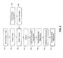
- FIG. 2is a flow diagram illustrating a method for optimizing brightness in a digital image according to an embodiment of the present invention.
- a digital image 103 representing a sceneis received in a receive digital image step 102 .
- the digital image 103can be captured by a digital camera or a scanner. Alternately, it may be a frame of a video sequence captured by a video camera.
- Range information 105 associated with the digital image 103is identified in identify range information step 104 .
- the range information 105includes distances of pixels in the scene from a known reference location.
- the viewpoint locationneeds to identified relative to the given range information.
- the viewpoint locationis the reference location.
- Range information 105is preferably presented in the form of a range map provided by a ranging camera which uses visible light, infrared light, laser light or ultrasound to determine distances to pixels in the scene.
- the range mapcan be provided using stereoscopic image processing techniques that involve capturing images of a scene from multiple viewpoints and determining the range information by evaluating the relative positions of objects in the scene.
- the range mapis preferably interpolated so that it has the same dimensions
- a plurality of objects 107is detected in the digital image based at least upon an analysis of the range information 105 .
- determine brightness adjustments step 108a brightness adjustment amount for each object is determined using an analysis which takes into account each object's distance from the viewpoint, which is the position of the camera.
- the f( ) functioncan be designed to compensate for the fact that exposure will fall off according to the well-known “inverse square law” relationship so that distant objects are brightened while closer objects are darkened.
- a brightness adjustment amount ⁇ of each object that was detected in detect object step 106is determined by taking an average of the brightness parameter values ⁇ (x, y) for every pixel in that object, as
- ⁇ j1 m ⁇ ⁇ i ⁇ ⁇ object ⁇ ⁇ j m ⁇ ⁇ ⁇ ( i ) , where ⁇ j is the brightness adjustment amount for the j th object and m is the number of pixels in the j th object.
- additional brightness parameterscan also be used.
- an additional brightness parametercan be based on the location of the pixel within the image (e.g., the brightness of pixels near the edges of the digital image may be increased to account for lens fall-off in the image).
- an additional brightness parametercan be based on local image structure (e.g., the brightness of pixels located at or near image locations having high edge gradient are may be increased).
- the brightness adjustment amounts for the detected objects 107can be specified by a user using a digital image editing application having a user interface.
- the user interfacewould allow the user to provide user input by selecting one of the detected objects 107 and specify a desired brightness adjustment amount, for example using a slide bar.
- the brightness adjustment amountcould be applied to the object 107 and a preview image could be presented to the user showing the new brightness level.
- the user-specified brightness adjustment amountscan be supplemental to the automatically determined brightness adjustment amounts, or alternatively they can be specified relative to the unadjusted object brightnesses in the original digital image 103 .
- the brightness adjustments for each objectare modified responsive to other factors.
- the dashed lines in FIG. 2indicate optional features.
- image analysis algorithmscan be used to identify which objects 107 correspond to people and the brightness adjustments can be modified accordingly.
- the resulting brightness adjustments 110are stored in a processor-accessible memory system using a store brightness adjustments step 111 .
- the brightness of each object in the digital image 103can be adjusted by applying each object's brightness adjustment 110 .
- Methods for modifying the brightness of an imageare well-known in the art.
- the brightness adjustment 110can be applied by linearly adding an offset to the pixel values.
- the brightness adjustment 110can be applied by nonlinearly scaling the pixel values by a constant multiplier.
- the brightness adjustment 110models the physical process of scaling the amount of light in the scene (e.g. a dimming or brightening of the source illumination).
- the brightness adjustments 110can also be applied in other ways.
- the L* (lightness) or the Y (luma) of an objectcan be shifted or nonlinearly modified when the digital image 103 is in the CIELAB color space or a YC r C b luma-chroma color space, respectively.
- FIG. 3is a flowchart illustrating additional details for the detect objects step 106 shown in FIG. 2 according to an embodiment of the present invention.
- the digital image 103 and range information 105are provided as inputs.
- a cluster map 203is generated based on an analysis of the range information 105 and the digital image 103 . Additional details of the generate cluster map step 202 will be described below with reference to FIG. 4 .
- the digital image Iwill be the digital image 103 .
- the function f( )works by identifying pixels in the cluster map 203 having the same distance, then assigning the corresponding pixels in the digital image 103 to a corresponding object 107 .
- FIG. 4is a flowchart illustrating additional details for the generate cluster map step 202 shown in FIG. 3 , according to an embodiment of the present invention.
- a digital image 103 and range information 105 including a range mapare provided as discussed earlier.
- cluster pixels step 304pixels in the range map are clustered by using a clustering algorithm such as the method described in “Dominant Sets and Pairwise Clustering” (IEEE Transactions on Pattern Analysis & Machine Intelligence, Vol. 29, No. 1, January 2007, pp. 167-172).
- the cluster groups generated in this mannertypically have a lot of noise.
- Reduce cluster noise step 306is used to reduce the cluster noise using a morphological method to fill small holes and remove small cluster regions.
- Edgesare detected in the digital image using an identify edges step 308 .
- the edgesare identified using a gradient operation.
- the gradient of an imageis defined as:
- I(x, y)is the intensity of pixel at location (x, y).
- filter edges step 310is used to filter the detected edges to remove insignificant edges and keep the significant edges.
- the filtering operationcan be expressed as:
- a refine clusters step 312is used refine the cluster groups and produce cluster map 203 .
- the boundary of cluster groupsare refined by using the significant edges computed in the filter edges step 310 . If pixels are outside of the detected significant edges in each cluster group, they will be removed. This will make the boundaries of the cluster groups much more accurate.
- an average distance, nis computed in each of the refined cluster group as:
- n1 m ⁇ ⁇ i ⁇ cluster ⁇ ⁇ w ⁇ dis ⁇ ( i ) , where m is the number of pixels in the cluster group w, dis(i) is the distance of the i th pixel to the viewpoint location.
Landscapes
- Engineering & Computer Science (AREA)
- Physics & Mathematics (AREA)
- General Physics & Mathematics (AREA)
- Theoretical Computer Science (AREA)
- Computer Vision & Pattern Recognition (AREA)
- Image Processing (AREA)
- Facsimile Image Signal Circuits (AREA)
Abstract
Description
α(x,y)=f(dis(x,y))
where α(x, y) is the brightness parameter of the pixel in location (x, y) in the digital image, dis(x, y) is the distance of this pixel from the viewpoint, and f( ) is a linear function or a nonlinear function such as a power function, a polynomial function or an exponential function. For example, to correct for brightness differences due to non-uniform lighting in a flash scene, the f( ) function can be designed to compensate for the fact that exposure will fall off according to the well-known “inverse square law” relationship so that distant objects are brightened while closer objects are darkened.
where γjis the brightness adjustment amount for the jthobject and m is the number of pixels in the jthobject.
objects=f(clustermap,I)
where the function f( ) is an object segmentation operation applied to the digital image I using the
where I(x, y) is the intensity of pixel at location (x, y). The magnitude of the gradient vector is:
G=[Gx2+Gy2]1/2.
Edges are detected in the digital image based on the magnitude of the gradient in each pixel.
where e is one of the detected edges, S(e) is the sum of gradient magnitudes of each pixel in the edge e, f is a filter mask and T is the threshold.
where m is the number of pixels in the cluster group w, dis(i) is the distance of the ithpixel to the viewpoint location. By assigning the average distance to each pixel in the cluster groups, the cluster map is generated.
- 10 Data processing system
- 20 Peripheral system
- 30 User interface system
- 40 Data storage system
- 102 Receive digital image step
- 103 Digital image
- 104 Identify range information step
- 105 Range information
- 106 Detect objects step
- 107 Objects
- 108 Determine brightness adjustments step
- 109 Modify brightness adjustments step
- 110 Brightness adjustments
- 111 Store brightness adjustments step
- 202 Generate cluster map step
- 203 Cluster map
- 204 Detect objects step
- 304 Cluster pixels step
- 306 Reduce cluster noise step
- 308 Identify edges step
- 310 Filter edges step
- 312 Refine clusters step
Claims (16)
Priority Applications (5)
| Application Number | Priority Date | Filing Date | Title |
|---|---|---|---|
| US12/533,325US8213052B2 (en) | 2009-07-31 | 2009-07-31 | Digital image brightness adjustment using range information |
| CN201080034042.7ACN102576456B (en) | 2009-07-31 | 2010-07-22 | Digital Image Brightness Adjustment Using Range Information |
| EP10740034AEP2460142A1 (en) | 2009-07-31 | 2010-07-22 | Digital image brightness adjustment using range information |
| JP2012522803AJP5906188B2 (en) | 2009-07-31 | 2010-07-22 | Brightness adjustment of digital images using range information |
| PCT/US2010/002070WO2011014236A1 (en) | 2009-07-31 | 2010-07-22 | Digital image brightness adjustment using range information |
Applications Claiming Priority (1)
| Application Number | Priority Date | Filing Date | Title |
|---|---|---|---|
| US12/533,325US8213052B2 (en) | 2009-07-31 | 2009-07-31 | Digital image brightness adjustment using range information |
Publications (2)
| Publication Number | Publication Date |
|---|---|
| US20110026051A1 US20110026051A1 (en) | 2011-02-03 |
| US8213052B2true US8213052B2 (en) | 2012-07-03 |
Family
ID=42633099
Family Applications (1)
| Application Number | Title | Priority Date | Filing Date |
|---|---|---|---|
| US12/533,325Expired - Fee RelatedUS8213052B2 (en) | 2009-07-31 | 2009-07-31 | Digital image brightness adjustment using range information |
Country Status (5)
| Country | Link |
|---|---|
| US (1) | US8213052B2 (en) |
| EP (1) | EP2460142A1 (en) |
| JP (1) | JP5906188B2 (en) |
| CN (1) | CN102576456B (en) |
| WO (1) | WO2011014236A1 (en) |
Cited By (1)
| Publication number | Priority date | Publication date | Assignee | Title |
|---|---|---|---|---|
| US9390481B2 (en) | 2013-05-05 | 2016-07-12 | Google Inc. | Enhancing content appearance |
Families Citing this family (15)
| Publication number | Priority date | Publication date | Assignee | Title |
|---|---|---|---|---|
| JP5175910B2 (en)* | 2010-09-16 | 2013-04-03 | 株式会社東芝 | Image processing apparatus, image processing method, and program |
| JP5254297B2 (en)* | 2010-09-27 | 2013-08-07 | 株式会社東芝 | Image processing device |
| US20120242795A1 (en) | 2011-03-24 | 2012-09-27 | Paul James Kane | Digital 3d camera using periodic illumination |
| JP5959019B2 (en)* | 2012-01-24 | 2016-08-02 | 公益財団法人名古屋産業科学研究所 | Gas separation membrane |
| US8964089B2 (en) | 2012-05-09 | 2015-02-24 | Canon Kabushiki Kaisha | Systems and methods for simulated preview for preferred image exposure |
| JP6040042B2 (en)* | 2013-02-12 | 2016-12-07 | アイキューブド研究所株式会社 | Image processing apparatus, image processing method, and program |
| US10764563B2 (en)* | 2014-11-13 | 2020-09-01 | Intel Corporation | 3D enhanced image correction |
| CN104517270A (en)* | 2014-12-25 | 2015-04-15 | 深圳市一体太赫兹科技有限公司 | Terahertz image processing method and system |
| US9626582B2 (en)* | 2014-12-30 | 2017-04-18 | Kodak Alaris Inc. | System and method for measuring mobile document image quality |
| KR102247526B1 (en) | 2015-07-10 | 2021-05-03 | 삼성전자주식회사 | Display apparatus and control method thereof |
| EP3540774B1 (en)* | 2018-03-16 | 2020-09-30 | Teledyne Dalsa B.V. | Image sensor and imaging system comprising the same |
| WO2020106629A1 (en)* | 2018-11-19 | 2020-05-28 | Intuitive Surgical Operations, Inc. | Systems and methods for emulating far-range lighting for an operational scene illuminated by close-range light |
| CN112153240B (en)* | 2019-06-27 | 2021-11-09 | 深圳Tcl数字技术有限公司 | Method and device for adjusting image quality and readable storage medium |
| CN112153298B (en)* | 2019-06-28 | 2022-03-01 | 北京地平线机器人技术研发有限公司 | Method and device for determining ideal brightness of target object |
| JP7398939B2 (en) | 2019-12-03 | 2023-12-15 | キヤノン株式会社 | Image processing device and its control method, imaging device, program, and storage medium |
Citations (37)
| Publication number | Priority date | Publication date | Assignee | Title |
|---|---|---|---|---|
| US4101217A (en) | 1975-06-08 | 1978-07-18 | Agfa-Gevaert A.G. | Automatic color printing apparatus |
| US4707119A (en) | 1984-08-31 | 1987-11-17 | Fuji Photo Film Co., Ltd. | Photographic printer |
| US4945406A (en) | 1988-11-07 | 1990-07-31 | Eastman Kodak Company | Apparatus and accompanying methods for achieving automatic color balancing in a film to video transfer system |
| US4984013A (en) | 1988-04-26 | 1991-01-08 | Fuji Photo Film Co., Ltd. | Method for controlling exposure amount in copying of color originals |
| US5016043A (en) | 1988-09-23 | 1991-05-14 | Gretag Systems | Exposure control process and photographic color copying apparatus |
| US6243133B1 (en) | 1997-03-07 | 2001-06-05 | Eastman Kodak Company | Method for automatic scene balance of digital images |
| US6252976B1 (en) | 1997-08-29 | 2001-06-26 | Eastman Kodak Company | Computer program product for redeye detection |
| US6275605B1 (en) | 1999-01-18 | 2001-08-14 | Eastman Kodak Company | Method for adjusting the tone scale of a digital image |
| US20020126893A1 (en) | 2001-01-31 | 2002-09-12 | Andreas Held | Automatic color defect correction |
| US20030007687A1 (en) | 2001-07-05 | 2003-01-09 | Jasc Software, Inc. | Correction of "red-eye" effects in images |
| US20030044070A1 (en) | 2001-09-03 | 2003-03-06 | Manfred Fuersich | Method for the automatic detection of red-eye defects in photographic image data |
| US20030044063A1 (en) | 2001-09-03 | 2003-03-06 | Guenter Meckes | Method for processing digital photographic image data that includes a method for the automatic detection of red-eye defects |
| US20030044178A1 (en) | 2001-09-03 | 2003-03-06 | Knut Oberhardt | Method for the automatic detection of red-eye defects in photographic image data |
| US6573932B1 (en) | 2002-03-15 | 2003-06-03 | Eastman Kodak Company | Method for automatic white balance of digital images |
| US6636646B1 (en) | 2000-07-20 | 2003-10-21 | Eastman Kodak Company | Digital image processing method and for brightness adjustment of digital images |
| US20030223622A1 (en) | 2002-05-31 | 2003-12-04 | Eastman Kodak Company | Method and system for enhancing portrait images |
| US20040240749A1 (en) | 2003-03-31 | 2004-12-02 | Seiko Epson Corporation | Image processing device, image processing method, and program |
| US6845181B2 (en) | 2001-07-12 | 2005-01-18 | Eastman Kodak Company | Method for processing a digital image to adjust brightness |
| US6873743B2 (en) | 2001-03-29 | 2005-03-29 | Fotonation Holdings, Llc | Method and apparatus for the automatic real-time detection and correction of red-eye defects in batches of digital images or in handheld appliances |
| US20050157204A1 (en) | 2004-01-16 | 2005-07-21 | Sony Computer Entertainment Inc. | Method and apparatus for optimizing capture device settings through depth information |
| US7043090B2 (en) | 2002-10-02 | 2006-05-09 | Eastman Kodak Company | Enhancing the tonal characteristics of digital images using expansive and compressive tone scale functions |
| US7046400B2 (en) | 2002-01-31 | 2006-05-16 | Eastman Kodak Company | Adjusting the color, brightness, and tone scale of rendered digital images |
| US7116838B2 (en) | 2002-10-25 | 2006-10-03 | Eastman Kodak Company | Enhancing the tonal and spatial characteristics of digital images using selective spatial filters |
| US7129980B1 (en) | 1999-01-25 | 2006-10-31 | Fuji Photo Film Co., Ltd. | Image capturing apparatus and automatic exposure control correcting method |
| US7158174B2 (en) | 2002-04-04 | 2007-01-02 | Eastman Kodak Company | Method for automatic white balance of digital images |
| US20070121094A1 (en) | 2005-11-30 | 2007-05-31 | Eastman Kodak Company | Detecting objects of interest in digital images |
| US20070126921A1 (en) | 2005-11-30 | 2007-06-07 | Eastman Kodak Company | Adjusting digital image exposure and tone scale |
| US7230538B2 (en) | 2004-06-11 | 2007-06-12 | Oriental Institute Of Technology | Apparatus and method for identifying surrounding environment by means of image processing and for outputting the results |
| US7289154B2 (en) | 2000-05-10 | 2007-10-30 | Eastman Kodak Company | Digital image processing method and apparatus for brightness adjustment of digital images |
| US20070274604A1 (en) | 2004-02-13 | 2007-11-29 | Yoav Schechner | Enhanced Underwater Imaging |
| US20080112616A1 (en) | 2006-11-14 | 2008-05-15 | Samsung Electronics Co., Ltd. | Method for adjusting disparity in three-dimensional image and three-dimensional imaging device thereof |
| WO2008102296A2 (en) | 2007-02-23 | 2008-08-28 | Koninklijke Philips Electronics N.V. | Method for enhancing the depth sensation of an image |
| US7421418B2 (en) | 2003-02-19 | 2008-09-02 | Nahava Inc. | Method and apparatus for fundamental operations on token sequences: computing similarity, extracting term values, and searching efficiently |
| US7421149B2 (en) | 2003-12-11 | 2008-09-02 | Sony United Kingdom Limited | Object detection |
| US7526127B2 (en) | 2003-09-12 | 2009-04-28 | Hiroshima University, A National University Corporation Of Japan | Image segmentation apparatus, image segmentation method, and image segmentation integrated circuit with low power consumption for large-scale images |
| WO2009072070A1 (en) | 2007-12-05 | 2009-06-11 | Nxp B.V. | Flash light compensation system for digital camera system |
| US7652716B2 (en)* | 2007-05-31 | 2010-01-26 | Microsoft Corporation | Computer-controlled lighting for video communication |
Family Cites Families (6)
| Publication number | Priority date | Publication date | Assignee | Title |
|---|---|---|---|---|
| JP2001005978A (en)* | 1999-06-18 | 2001-01-12 | Sony Corp | Device and method for extracting object, and program providing medium |
| JP2003304562A (en)* | 2002-04-10 | 2003-10-24 | Victor Co Of Japan Ltd | Object encoding method, object encoder, and program for object encoding |
| JP2004148704A (en)* | 2002-10-31 | 2004-05-27 | Kyocera Mita Corp | Image processing method and image processor |
| JP2004282532A (en)* | 2003-03-18 | 2004-10-07 | Ricoh Co Ltd | Image processing device |
| JP2006279546A (en)* | 2005-03-29 | 2006-10-12 | Nikon Corp | Electronic camera, image processing program, and image processing method |
| JP4916378B2 (en)* | 2007-05-15 | 2012-04-11 | 三洋電機株式会社 | Imaging apparatus, image processing apparatus, image file, and gradation correction method |
- 2009
- 2009-07-31USUS12/533,325patent/US8213052B2/ennot_activeExpired - Fee Related
- 2010
- 2010-07-22CNCN201080034042.7Apatent/CN102576456B/ennot_activeExpired - Fee Related
- 2010-07-22JPJP2012522803Apatent/JP5906188B2/enactiveActive
- 2010-07-22WOPCT/US2010/002070patent/WO2011014236A1/enactiveApplication Filing
- 2010-07-22EPEP10740034Apatent/EP2460142A1/ennot_activeWithdrawn
Patent Citations (37)
| Publication number | Priority date | Publication date | Assignee | Title |
|---|---|---|---|---|
| US4101217A (en) | 1975-06-08 | 1978-07-18 | Agfa-Gevaert A.G. | Automatic color printing apparatus |
| US4707119A (en) | 1984-08-31 | 1987-11-17 | Fuji Photo Film Co., Ltd. | Photographic printer |
| US4984013A (en) | 1988-04-26 | 1991-01-08 | Fuji Photo Film Co., Ltd. | Method for controlling exposure amount in copying of color originals |
| US5016043A (en) | 1988-09-23 | 1991-05-14 | Gretag Systems | Exposure control process and photographic color copying apparatus |
| US4945406A (en) | 1988-11-07 | 1990-07-31 | Eastman Kodak Company | Apparatus and accompanying methods for achieving automatic color balancing in a film to video transfer system |
| US6243133B1 (en) | 1997-03-07 | 2001-06-05 | Eastman Kodak Company | Method for automatic scene balance of digital images |
| US6252976B1 (en) | 1997-08-29 | 2001-06-26 | Eastman Kodak Company | Computer program product for redeye detection |
| US6275605B1 (en) | 1999-01-18 | 2001-08-14 | Eastman Kodak Company | Method for adjusting the tone scale of a digital image |
| US7129980B1 (en) | 1999-01-25 | 2006-10-31 | Fuji Photo Film Co., Ltd. | Image capturing apparatus and automatic exposure control correcting method |
| US7289154B2 (en) | 2000-05-10 | 2007-10-30 | Eastman Kodak Company | Digital image processing method and apparatus for brightness adjustment of digital images |
| US6636646B1 (en) | 2000-07-20 | 2003-10-21 | Eastman Kodak Company | Digital image processing method and for brightness adjustment of digital images |
| US20020126893A1 (en) | 2001-01-31 | 2002-09-12 | Andreas Held | Automatic color defect correction |
| US6873743B2 (en) | 2001-03-29 | 2005-03-29 | Fotonation Holdings, Llc | Method and apparatus for the automatic real-time detection and correction of red-eye defects in batches of digital images or in handheld appliances |
| US20030007687A1 (en) | 2001-07-05 | 2003-01-09 | Jasc Software, Inc. | Correction of "red-eye" effects in images |
| US6845181B2 (en) | 2001-07-12 | 2005-01-18 | Eastman Kodak Company | Method for processing a digital image to adjust brightness |
| US20030044063A1 (en) | 2001-09-03 | 2003-03-06 | Guenter Meckes | Method for processing digital photographic image data that includes a method for the automatic detection of red-eye defects |
| US20030044178A1 (en) | 2001-09-03 | 2003-03-06 | Knut Oberhardt | Method for the automatic detection of red-eye defects in photographic image data |
| US20030044070A1 (en) | 2001-09-03 | 2003-03-06 | Manfred Fuersich | Method for the automatic detection of red-eye defects in photographic image data |
| US7046400B2 (en) | 2002-01-31 | 2006-05-16 | Eastman Kodak Company | Adjusting the color, brightness, and tone scale of rendered digital images |
| US6573932B1 (en) | 2002-03-15 | 2003-06-03 | Eastman Kodak Company | Method for automatic white balance of digital images |
| US7158174B2 (en) | 2002-04-04 | 2007-01-02 | Eastman Kodak Company | Method for automatic white balance of digital images |
| US20030223622A1 (en) | 2002-05-31 | 2003-12-04 | Eastman Kodak Company | Method and system for enhancing portrait images |
| US7043090B2 (en) | 2002-10-02 | 2006-05-09 | Eastman Kodak Company | Enhancing the tonal characteristics of digital images using expansive and compressive tone scale functions |
| US7116838B2 (en) | 2002-10-25 | 2006-10-03 | Eastman Kodak Company | Enhancing the tonal and spatial characteristics of digital images using selective spatial filters |
| US7421418B2 (en) | 2003-02-19 | 2008-09-02 | Nahava Inc. | Method and apparatus for fundamental operations on token sequences: computing similarity, extracting term values, and searching efficiently |
| US20040240749A1 (en) | 2003-03-31 | 2004-12-02 | Seiko Epson Corporation | Image processing device, image processing method, and program |
| US7526127B2 (en) | 2003-09-12 | 2009-04-28 | Hiroshima University, A National University Corporation Of Japan | Image segmentation apparatus, image segmentation method, and image segmentation integrated circuit with low power consumption for large-scale images |
| US7421149B2 (en) | 2003-12-11 | 2008-09-02 | Sony United Kingdom Limited | Object detection |
| US20050157204A1 (en) | 2004-01-16 | 2005-07-21 | Sony Computer Entertainment Inc. | Method and apparatus for optimizing capture device settings through depth information |
| US20070274604A1 (en) | 2004-02-13 | 2007-11-29 | Yoav Schechner | Enhanced Underwater Imaging |
| US7230538B2 (en) | 2004-06-11 | 2007-06-12 | Oriental Institute Of Technology | Apparatus and method for identifying surrounding environment by means of image processing and for outputting the results |
| US20070126921A1 (en) | 2005-11-30 | 2007-06-07 | Eastman Kodak Company | Adjusting digital image exposure and tone scale |
| US20070121094A1 (en) | 2005-11-30 | 2007-05-31 | Eastman Kodak Company | Detecting objects of interest in digital images |
| US20080112616A1 (en) | 2006-11-14 | 2008-05-15 | Samsung Electronics Co., Ltd. | Method for adjusting disparity in three-dimensional image and three-dimensional imaging device thereof |
| WO2008102296A2 (en) | 2007-02-23 | 2008-08-28 | Koninklijke Philips Electronics N.V. | Method for enhancing the depth sensation of an image |
| US7652716B2 (en)* | 2007-05-31 | 2010-01-26 | Microsoft Corporation | Computer-controlled lighting for video communication |
| WO2009072070A1 (en) | 2007-12-05 | 2009-06-11 | Nxp B.V. | Flash light compensation system for digital camera system |
Non-Patent Citations (5)
| Title |
|---|
| "Dominant Sets and Pairwise Clustering", by Massimiliano Pavan et al., IEEE Transactions on Pattern Analysis & Machine Intelligence, vol. 29, No. 1, Jan. 2007, pp. 167-172. |
| "Object Detection using a Max-Margin Hough Transform" by S. Maji et al., Proc. IEEE Conf. on Computer Vision and Pattern Recognition, 2009. |
| "Object Segmentation Using Graph Cuts Based Active Contours" by N. Xu et al., Proc. IEEE Conf. on Computer Vision and Pattern Recognition, 2003. |
| "Object-Specific Figure-Ground Segregation" by S. X. Yu, et al., Proc. IEE Conf. on Computer Vision and Pattern Recognition, 2003. |
| A. Hoover et al.: "An Experimental Comparison of Range Image Segmentation Algorithms", IEEE Transactions on Pattern Analysis and Machine Intelligence, IEEE Service Center, Los Alamitos, CA, US LNKD-DOI:10.1109/34.506791, vol. 18, No. 7, Jul. 1, 1996, pp. 673-689, XP002213073, ISSN: 0162-8828, p. 674; Table 1. |
Cited By (1)
| Publication number | Priority date | Publication date | Assignee | Title |
|---|---|---|---|---|
| US9390481B2 (en) | 2013-05-05 | 2016-07-12 | Google Inc. | Enhancing content appearance |
Also Published As
| Publication number | Publication date |
|---|---|
| WO2011014236A1 (en) | 2011-02-03 |
| US20110026051A1 (en) | 2011-02-03 |
| JP5906188B2 (en) | 2016-04-20 |
| CN102576456A (en) | 2012-07-11 |
| EP2460142A1 (en) | 2012-06-06 |
| CN102576456B (en) | 2017-04-05 |
| JP2013501264A (en) | 2013-01-10 |
Similar Documents
| Publication | Publication Date | Title |
|---|---|---|
| US8213052B2 (en) | Digital image brightness adjustment using range information | |
| US10205896B2 (en) | Automatic lens flare detection and correction for light-field images | |
| US8509519B2 (en) | Adjusting perspective and disparity in stereoscopic image pairs | |
| US6952286B2 (en) | Doubleprint photofinishing service with the second print having subject content-based modifications | |
| US8391593B2 (en) | Image processing methods and systems | |
| US10019823B2 (en) | Combined composition and change-based models for image cropping | |
| US9020243B2 (en) | Image adjustment | |
| US8588548B2 (en) | Method for forming a composite image | |
| US8787659B2 (en) | Automatic adaptation to image processing pipeline | |
| US20060126944A1 (en) | Variance-based event clustering | |
| US8374454B2 (en) | Detection of objects using range information | |
| US11763430B2 (en) | Correcting dust and scratch artifacts in digital images | |
| RU2370815C2 (en) | Method and system for separation and classification of defects in exposure of digital images | |
| JP2003344021A (en) | Method for calculating dimension of human face in image and method for detecting face | |
| KR101731729B1 (en) | Methods for generating hdr (high dynamic range) images and apparatuses using the same | |
| WO2018228310A1 (en) | Image processing method and apparatus, and terminal | |
| CN110688926B (en) | Subject detection method and device, electronic device, computer-readable storage medium | |
| US8218823B2 (en) | Determining main objects using range information | |
| CN110933304B (en) | Method and device for determining to-be-blurred region, storage medium and terminal equipment | |
| US11915480B2 (en) | Image processing apparatus and image processing method | |
| KR102026308B1 (en) | Method for removing shadows from images | |
| CN119277203A (en) | A method, device, terminal equipment and storage medium for calibrating clarity based on moving head light | |
| German et al. | Improving scans of black and white photographs by recovering the print maker's artistic intent |
Legal Events
| Date | Code | Title | Description |
|---|---|---|---|
| AS | Assignment | Owner name:EASTMAN KODAK COMPANY, NEW YORK Free format text:ASSIGNMENT OF ASSIGNORS INTEREST;ASSIGNOR:WANG, SEN;REEL/FRAME:023036/0590 Effective date:20090731 | |
| AS | Assignment | Owner name:CITICORP NORTH AMERICA, INC., AS AGENT, NEW YORK Free format text:SECURITY INTEREST;ASSIGNORS:EASTMAN KODAK COMPANY;PAKON, INC.;REEL/FRAME:028201/0420 Effective date:20120215 | |
| STCF | Information on status: patent grant | Free format text:PATENTED CASE | |
| AS | Assignment | Owner name:KODAK (NEAR EAST), INC., NEW YORK Free format text:PATENT RELEASE;ASSIGNORS:CITICORP NORTH AMERICA, INC.;WILMINGTON TRUST, NATIONAL ASSOCIATION;REEL/FRAME:029913/0001 Effective date:20130201 Owner name:KODAK IMAGING NETWORK, INC., CALIFORNIA Free format text:PATENT RELEASE;ASSIGNORS:CITICORP NORTH AMERICA, INC.;WILMINGTON TRUST, NATIONAL ASSOCIATION;REEL/FRAME:029913/0001 Effective date:20130201 Owner name:EASTMAN KODAK COMPANY, NEW YORK Free format text:PATENT RELEASE;ASSIGNORS:CITICORP NORTH AMERICA, INC.;WILMINGTON TRUST, NATIONAL ASSOCIATION;REEL/FRAME:029913/0001 Effective date:20130201 Owner name:KODAK AVIATION LEASING LLC, NEW YORK Free format text:PATENT RELEASE;ASSIGNORS:CITICORP NORTH AMERICA, INC.;WILMINGTON TRUST, NATIONAL ASSOCIATION;REEL/FRAME:029913/0001 Effective date:20130201 Owner name:KODAK REALTY, INC., NEW YORK Free format text:PATENT RELEASE;ASSIGNORS:CITICORP NORTH AMERICA, INC.;WILMINGTON TRUST, NATIONAL ASSOCIATION;REEL/FRAME:029913/0001 Effective date:20130201 Owner name:PAKON, INC., INDIANA Free format text:PATENT RELEASE;ASSIGNORS:CITICORP NORTH AMERICA, INC.;WILMINGTON TRUST, NATIONAL ASSOCIATION;REEL/FRAME:029913/0001 Effective date:20130201 Owner name:EASTMAN KODAK INTERNATIONAL CAPITAL COMPANY, INC., Free format text:PATENT RELEASE;ASSIGNORS:CITICORP NORTH AMERICA, INC.;WILMINGTON TRUST, NATIONAL ASSOCIATION;REEL/FRAME:029913/0001 Effective date:20130201 Owner name:LASER-PACIFIC MEDIA CORPORATION, NEW YORK Free format text:PATENT RELEASE;ASSIGNORS:CITICORP NORTH AMERICA, INC.;WILMINGTON TRUST, NATIONAL ASSOCIATION;REEL/FRAME:029913/0001 Effective date:20130201 Owner name:FAR EAST DEVELOPMENT LTD., NEW YORK Free format text:PATENT RELEASE;ASSIGNORS:CITICORP NORTH AMERICA, INC.;WILMINGTON TRUST, NATIONAL ASSOCIATION;REEL/FRAME:029913/0001 Effective date:20130201 Owner name:NPEC INC., NEW YORK Free format text:PATENT RELEASE;ASSIGNORS:CITICORP NORTH AMERICA, INC.;WILMINGTON TRUST, NATIONAL ASSOCIATION;REEL/FRAME:029913/0001 Effective date:20130201 Owner name:QUALEX INC., NORTH CAROLINA Free format text:PATENT RELEASE;ASSIGNORS:CITICORP NORTH AMERICA, INC.;WILMINGTON TRUST, NATIONAL ASSOCIATION;REEL/FRAME:029913/0001 Effective date:20130201 Owner name:CREO MANUFACTURING AMERICA LLC, WYOMING Free format text:PATENT RELEASE;ASSIGNORS:CITICORP NORTH AMERICA, INC.;WILMINGTON TRUST, NATIONAL ASSOCIATION;REEL/FRAME:029913/0001 Effective date:20130201 Owner name:FPC INC., CALIFORNIA Free format text:PATENT RELEASE;ASSIGNORS:CITICORP NORTH AMERICA, INC.;WILMINGTON TRUST, NATIONAL ASSOCIATION;REEL/FRAME:029913/0001 Effective date:20130201 Owner name:KODAK PORTUGUESA LIMITED, NEW YORK Free format text:PATENT RELEASE;ASSIGNORS:CITICORP NORTH AMERICA, INC.;WILMINGTON TRUST, NATIONAL ASSOCIATION;REEL/FRAME:029913/0001 Effective date:20130201 Owner name:KODAK PHILIPPINES, LTD., NEW YORK Free format text:PATENT RELEASE;ASSIGNORS:CITICORP NORTH AMERICA, INC.;WILMINGTON TRUST, NATIONAL ASSOCIATION;REEL/FRAME:029913/0001 Effective date:20130201 Owner name:KODAK AMERICAS, LTD., NEW YORK Free format text:PATENT RELEASE;ASSIGNORS:CITICORP NORTH AMERICA, INC.;WILMINGTON TRUST, NATIONAL ASSOCIATION;REEL/FRAME:029913/0001 Effective date:20130201 | |
| AS | Assignment | Owner name:INTELLECTUAL VENTURES FUND 83 LLC, NEVADA Free format text:ASSIGNMENT OF ASSIGNORS INTEREST;ASSIGNOR:EASTMAN KODAK COMPANY;REEL/FRAME:030264/0522 Effective date:20130201 | |
| FPAY | Fee payment | Year of fee payment:4 | |
| AS | Assignment | Owner name:MONUMENT PEAK VENTURES, LLC, TEXAS Free format text:ASSIGNMENT OF ASSIGNORS INTEREST;ASSIGNOR:INTELLECTUAL VENTURES FUND 83 LLC;REEL/FRAME:041941/0079 Effective date:20170215 | |
| FEPP | Fee payment procedure | Free format text:MAINTENANCE FEE REMINDER MAILED (ORIGINAL EVENT CODE: REM.); ENTITY STATUS OF PATENT OWNER: LARGE ENTITY | |
| LAPS | Lapse for failure to pay maintenance fees | Free format text:PATENT EXPIRED FOR FAILURE TO PAY MAINTENANCE FEES (ORIGINAL EVENT CODE: EXP.); ENTITY STATUS OF PATENT OWNER: LARGE ENTITY | |
| STCH | Information on status: patent discontinuation | Free format text:PATENT EXPIRED DUE TO NONPAYMENT OF MAINTENANCE FEES UNDER 37 CFR 1.362 | |
| FP | Lapsed due to failure to pay maintenance fee | Effective date:20200703 | |
| AS | Assignment | Owner name:MONUMENT PEAK VENTURES, LLC, TEXAS Free format text:RELEASE BY SECURED PARTY;ASSIGNOR:INTELLECTUAL VENTURES FUND 83 LLC;REEL/FRAME:064599/0304 Effective date:20230728 |