US8212548B2 - Branch meter with configurable sensor strip arrangement - Google Patents
Branch meter with configurable sensor strip arrangementDownload PDFInfo
- Publication number
- US8212548B2 US8212548B2US12/455,512US45551209AUS8212548B2US 8212548 B2US8212548 B2US 8212548B2US 45551209 AUS45551209 AUS 45551209AUS 8212548 B2US8212548 B2US 8212548B2
- Authority
- US
- United States
- Prior art keywords
- sensor
- sensor array
- array
- output
- orientation
- Prior art date
- Legal status (The legal status is an assumption and is not a legal conclusion. Google has not performed a legal analysis and makes no representation as to the accuracy of the status listed.)
- Active, expires
Links
- 238000012544monitoring processMethods0.000claimsabstractdescription24
- 239000004020conductorSubstances0.000claimsdescription16
- 238000005259measurementMethods0.000claimsdescription10
- 238000000034methodMethods0.000claims6
- 230000005611electricityEffects0.000claims5
- 238000003491arrayMethods0.000abstract1
- 238000009434installationMethods0.000description7
- 230000008901benefitEffects0.000description2
- 230000014509gene expressionEffects0.000description2
- 230000001052transient effectEffects0.000description2
- 230000003466anti-cipated effectEffects0.000description1
- 239000002131composite materialSubstances0.000description1
- 238000001816coolingMethods0.000description1
- 230000008878couplingEffects0.000description1
- 238000010168coupling processMethods0.000description1
- 238000005859coupling reactionMethods0.000description1
- 238000000354decomposition reactionMethods0.000description1
- 230000007423decreaseEffects0.000description1
- 230000009977dual effectEffects0.000description1
- 238000010438heat treatmentMethods0.000description1
- 230000035939shockEffects0.000description1
- 238000006467substitution reactionMethods0.000description1
Images


Classifications
- G—PHYSICS
- G01—MEASURING; TESTING
- G01R—MEASURING ELECTRIC VARIABLES; MEASURING MAGNETIC VARIABLES
- G01R21/00—Arrangements for measuring electric power or power factor
- G—PHYSICS
- G01—MEASURING; TESTING
- G01R—MEASURING ELECTRIC VARIABLES; MEASURING MAGNETIC VARIABLES
- G01R22/00—Arrangements for measuring time integral of electric power or current, e.g. electricity meters
- G01R22/06—Arrangements for measuring time integral of electric power or current, e.g. electricity meters by electronic methods
- G01R22/061—Details of electronic electricity meters
- G01R22/065—Details of electronic electricity meters related to mechanical aspects
Definitions
- the present inventionrelates to a power monitoring system.
- many electrical power distribution systemsinclude a panel enclosure 10 into which is provided electrical power using one or more sets of wires 12 .
- the electrical powermay have any voltage, any current, and any number of phases (e.g., single phase, two phases, or three phases).
- Each phase of the electrical power to the power panelis normally provided to a separate bus bar 14 a , 14 b , and 14 c , which are normally elongate conductors within the power panel 10 .
- a plurality of circuit breakers 16 a , 16 b , and 16 c , etc., which trip or otherwise selectively disconnect electrical power,are electrically interconnected between one or more of the bus bars 14 a , 14 b , and 14 c , and respective loads 18 external to the power panel 10 .
- the circuit breakers 16are vertically aligned in one or more strips.
- the load 18 interconnected to a respective circuit breaker 16 within the power panel 10draws excessive electrical current then the circuit breaker 16 trips or otherwise disconnects the electrical power to the load 18 . In this manner, if a load shorts and thereafter draws excessive current then the circuit breaker will trip. Frequently the load will be a three-phase load having three wires provided thereto, with one or more corresponding circuit breakers.
- a set of electrical loadssuch as motors, lighting, heating units, cooling units, machinery, etc.
- Obtaining the total power usage of the businessmay be readily obtained by reading the power meter provided by the power utility.
- the power meteris normally electrically interconnected between the power panel and the power utility.
- the use of power meterspermits effective monitoring of the power consumption of particular loads.
- a set of power meterspermits effective sub-metering of different loads, buildings, or groups of loads to attribute and monitor the power usage of the business.
- the power sub-meteringmay be used to attribute the power costs charged by the utility to different buildings, departments, or cost centers.
- the traditional approach to monitoring such power usageis to install a power meter at a location proximate the load itself.
- a current sensoris located around each wire of the three phases and a voltage connection is electrically interconnected to each wire.
- Such a power meteris available from Veris Industries, LLC under the name H8035 Power Meter. Unfortunately, the installation of such a system is prone to configuration error by the installer.
- FIG. 1illustrates a power panel with circuit breakers.
- FIG. 2illustrates circuit breakers, associated sensors, and a power monitor.
- FIG. 3illustrates a perspective view of an exemplary embodiment of a support for a set of current sensors.
- FIG. 4illustrates a side view of the support and sensors of FIG. 3 .
- FIG. 5illustrates a top view of the support and sensors of FIG. 3 .
- FIG. 6illustrates a top view of the support and sensors of FIG. 2 together with circuit breakers.
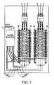
- FIG. 7illustrates a power panel assembly with a power monitor and the support/current sensors of FIG. 3 with a top feed.
- FIG. 8illustrates a power panel assembly with a power monitor and the support/current sensors of FIG. 3 with a bottom feed.
- FIG. 9illustrates a power panel assembly with a power monitor and the support/current sensors of FIG. 3 with a top feed and a numbering scheme.
- FIG. 10illustrates a power panel assembly with a power monitor and the support/current sensors of FIG. 3 with a bottom feed and a numbering scheme consistent with FIG. 9 .
- FIG. 11illustrates a power panel assembly with a power monitor and the support/current sensors of FIG. 3 with a top feed and a sequential numbering scheme.
- FIG. 12illustrates a power panel assembly with a power monitor and the support/current sensors of FIG. 3 with a top feed and an even/odd numbering scheme.
- FIG. 13illustrates a power panel assembly with a power monitor and the support/current sensors of FIG. 3 with a top feed and dual columns of sensors.
- a respective current sensor 20may be interconnected to the wire on the load side of the respective circuit breaker 16 .
- Typical circuit breakersmay include a single phase, two phases, or three phases.
- the outputs 22 of each of the current sensors 20may be interconnected to a power monitor 24 .
- the current sensors 20may be interconnected to one or more power monitors. Also, the current sensors 20 may likewise be daisy chained together, or interconnected to the power monitor(s) in any other suitable manner.
- An electrical interconnection from each bus bar to the power monitor(s)normally includes wires 23 a , 23 b , 23 c , to sense the voltage and its corresponding phase relationship.
- the voltage potential and phase relationship for each phasemay be sensed from locations other than the bus bars 14 a , 14 b , and 14 c , such as for example, a wire provided to a load, the load side of a circuit breaker, the utility side of a circuit breaker, a capacitive coupling to the voltage potential, or the wire connection from the utility.
- the power monitormay calculate power based upon a single phase, two phases, and/or three phases, etc., as desired. In essence, the power monitoring system may use the electrical path from the power monitor 24 to the bus bars (or otherwise) of at least one of the phases for a plurality of different loads. Typically, the power is calculated by multiplying the voltage, corresponding current, and corresponding power factor which relates to the phase relationship between the voltage and current. In some embodiments, the power monitor will not calculate power but provide the current measurements for each of the loads to the user.
- a set of sensors 60may be supported by a support 62 which maintains the current sensors 60 in a fixed spatial relationship with respect to one another.
- the support 62is rigid or semi-rigid, while a flexible support 62 that was installed on a rigid or a semi-rigid supporting member(s) may likewise be used.
- the sensors 60are preferably current sensors, or alternatively, other types of sensors may be used.
- the sensors 60are preferably wire wound torodial coils on a metallic or non-metallic core enclosed within a plastic housing through which a wire 63 may be extended, and the housings are at least partially surrounding the respective coil. Changing current within the wire 63 induces a changing magnetic field around the wire 63 . The changing magnetic field in turn induces a changing current within the wire wound torodial coil.
- the changing current within the torodial coilmay be used directly or converted to any suitable signal, such as for example, a voltage signal, or a different current signal.
- the openings 64 defined by the sensors 60are preferably oriented in a substantially parallel relationship with respect to each other and/or oriented in a substantially perpendicular relationship with respect to the longitudinal axis 66 of the support 62 or otherwise the general alignment of the sensors.
- one set of the aligned sensorshave a first linear arrangement and another set of the aligned sensors have a second linear arrangement, which may be parallel to each other.
- at least two of the aligned sensorshave a first linear arrangement and at least two others of the aligned sensors have a second linear arrangement.
- a single aligned set of sensors 60may be used or more than two sets of sensors 60 may be used, as desired.
- the sensors 60may be arranged such that the housings surrounding the current sensors have an overlapping region 70 in a substantially perpendicular direction with respect to the longitudinal axis of the support 62 and/or general alignment of the sensors.
- the openings 64 defined by the sensors 60are in a non-overlapping relationship 72 with respect to one another and a non-overlapping relationship 74 with respect to other housings. This permits the sensors to be arranged in a more compact arrangement within the power panel.
- a respective transient voltage suppressor 80may be interconnected in parallel across the output terminals of each sensor 60 .
- the transient voltage suppressors 80limits the voltage build up at the terminals of the sensors 60 , which may occur if the sensors are sensing a changing magnetic field while the terminals of the sensors 60 are open circuited. This decreases the likelihood that technicians will be the recipient of an unanticipated electrical shock.
- the current sensors 60are preferably arranged in a spatial arrangement such that the openings 64 defined by the current sensors 60 are in a substantially directly opposing relationship with respect to the circuit breakers 16 .
- the each of the openings 64is opposing a respective circuit breaker 16 .
- the wires from the circuit breakers 16may be readily routed through a respective sensor 60 .
- the support 62is initially affixed within the power panel in an adjacent spaced apart relationship with respect to a set of circuit breakers 16 .
- a supportmay be located on both sides of a set of circuit breakers 16 , if desired.
- the wires from the loadsare passed through the respective sensors and interconnected to a respective circuit breaker 16 .
- the wires 23 a , 23 b , and 23 cfor sensing the voltage potentials on the bus bars are likewise electrically interconnected. In this manner, the installation of the circuit breakers and the power monitor is efficient, less expensive, economical, and the sensors are in a suitable position with respect to the respective circuit breakers.
- the support 62may be suitable for supporting a set of electrical traces that interconnect the sensors 60 to a connector 82 .
- the interconnections from the sensors 60 to the connector 82are predetermined so that the signals provided to the connector 82 are readily identifiable to the proper sensor 60 . This eliminates the potential possibility of improperly interconnecting the wires from the sensors 60 to the connector.
- the interrelationship between each of the sensorsis predefined. Accordingly, at each respective connector it is known the relative relationship between each of the sensors.
- a cable 84interconnects each connector 82 to a power monitor 24 .
- the sensors 60may be constructed in a split-core manner. In this manner, the opening 64 may be opened, the wire inserted therein, and the opening 64 closed around substantially all of the wire.
- the power monitor 24may monitor the current levels of each of circuit breakers 16 together with the associated voltage potential and phase relationship.
- the power monitor 24can be pre-programmed to calculate power (or provide current measurements) based upon the arrangement of the sensors relative to the circuit breakers. In this manner, the arrangement of circuit breakers is known and thus the current sensors on either side of the breakers is likewise known. With known relationships, the output of the power monitor provides data for each of the circuit breakers in a known and repeatable manner. Moreover, the potential for installation errors of the strips is greatly reduced.
- the connectors 82are arranged distant from the utility connection for safety reasons.
- the utility connectioni.e., any power connection from outside of the enclosure
- the top of the enclosureas illustrated in FIG. 7
- the bottom of the enclosureas illustrated in FIG. 8
- the connectorsare at one or both sides of the enclosure.
- the strip configurationpotentially being installed with different orientations, the same sensor would be associated with different circuit breakers.
- the stripmay be installed with the connector at the bottom or the connector at the top.
- the power monitoris capable of being configured to automatically account for the different configurations in a transparent manner to the user. In this manner, each circuit breaker is associated with a known sensor in a manner independent of the orientation of the strip.
- the power connectorsare at the top of the panel.
- the circuit breakersare normally arranged in a vertical orientation, in either one or two columns.
- the connectors 82are preferably at the bottom of the circuit panel. Accordingly, this configuration may be referred to as a top feed panel.
- the sensorsmay have a numbering convention with the odd numbered sensors on the left and the even numbered current sensors on the right. Each of the odd numbers and even numbers are arranged in a sequential manner from top to bottom. In this manner, the power monitor is configured to know the physical position of the upper left hand circuit breaker as being associated with sensor 1 , the second upper left hand circuit breaker as being associated with sensor 3 , and so forth. Other numbering conventions may likewise be used.
- the power connectorsare at the bottom of the panel.
- the circuit breakersare normally arranged in a vertical orientation, in either one or two columns.
- the connectors 82are preferably at the top of the circuit panel. Accordingly, this configuration may be referred to as a bottom feed panel.
- the sensorsmay have a numbering convention with the odd numbered sensors on the left and the even numbered current sensors on the right. Each of the odd numbers and even numbers are arranged in a sequential manner from top to bottom. In this manner, the power monitor is configured to know the physical position of the upper left hand circuit breaker as being associated with sensor 1 , the second upper left hand circuit breaker as being associated with sensor 3 , and so forth. Other numbering conventions may likewise be used.
- a switch 25 or other identification mechanismmay be used by the power monitor to distinguish between a top feeding ( FIG. 9 ) and a bottom feeding configuration ( FIG. 10 ).
- the switch or other identification mechanismmay likewise be used to distinguish between other configurations.
- the power monitorthen makes the appropriate substitutions of the sensed values to provide an output that is consistent between the top feeding and bottom feeding configurations (or other configurations). In either case, from the user's perspective the top feeding and bottom feeding configurations (or other configurations) are the same.
- the power connectorsare at the top of the panel.
- the circuit breakersare normally arranged in a vertical orientation, in either one or two columns.
- the connectors 82are preferably at the top of the circuit panel and the bottom of the circuit panel on one side of the circuit breakers. Accordingly, this configuration may be referred to as a top feed panel single row.
- the sensorsmay have a numbering convention with the sensors numbered in a sequential manner from top to bottom. Each of the strips are sequentially numbered between strips. In this manner, the power monitor is configured to know the physical position of the upper left hand circuit breaker as being associated with sensor 1 , the second upper left hand circuit breaker as being associated with sensor 2 , and so forth.
- the power connectorsare at the top of the panel.
- the circuit breakersare normally arranged in a vertical orientation, in either one or two columns.
- the connectors 82are preferably at the top of the circuit panel and the bottom of the circuit panel on one side of the circuit breakers. Accordingly, this configuration may be referred to as a top feed panel single row.
- the sensorsmay have a numbering convention with the sensors numbered in a sequential even manner from top to bottom of the upper strip and sequential odd manner from top to bottom of the lower strip.
- the power monitoris configured to know the physical position of the upper left hand circuit breaker as being associated with sensor 1 , the second upper left hand circuit breaker as being associated with sensor 3 , and so forth.
- the stripsmay be configured such that they are suitable for top feeding or bottom feeding configuration. In either case, the numbering scheme between top feeding and bottom feeding configurations should be the same.
- the stripsmay be configured to be on both sides of the circuit breakers, if desired.
- the number scheme for the stripsmay be similar to that illustrated in FIG. 9 and/or FIG. 10 and/or FIG. 11 and/or FIG. 12 .
- the stripsmay be configured such that they are suitable for top feeding or bottom feeding configuration. In either case, the numbering scheme between top feeding and bottom feeding configurations should be the same.
- the power factor for one or more phasesmay be presumed to be a constant value.
- the power factor(normally the cosine of the phase difference) may be based upon historical measurements, test measurements, anticipated power factor, desired power factor, or otherwise omitted from the calculation of power usage (equivalent to using a power factor of “1”).
- the power factor, the voltage potential, and/or the currentmay be calculated, sensed, or otherwise measured for a single phase of a multi-phase load.
- the power monitormay then use the voltage potential and current, together with the power factor if desired, to calculate the power usage of a multi-phase load by presuming that the remaining phases have similar characteristics. For example, in a three phase system the remaining phases may be presumed to have approximately a 60 degree phase difference. Reusing power calculations for other phases reduces the computation complexity of the power monitor while maintaining relatively accurate power measurements.
- the power factor of a multi-phase loadmay be determined based upon one of the voltages and one of the currents, both of which are preferably associated with the same phase.
- the power factormay then be used for all of the phases, if desired. Reusing the calculated power factor reduces the computational complexity of the power monitor while maintaining relatively accurate power measurements.
- the power monitormay, if desired, separate multiple summed alternating voltage signals into their respective phases for power determination, typically by decomposition of the composite signal.
- multiple electrical interconnectionsmay be provided from the power monitor to each of the multiple bus bars or otherwise the voltage potentials of the different phases. Preferably, at least one of the electrical interconnections from the power monitor to at least one of the multiple bus bars, or otherwise the voltage potential of at least one phase, is used together with different current sensors for a plurality of different loads.
- all or a portion of the power monitoring systemmay be located outside of the power panel.
Landscapes
- Engineering & Computer Science (AREA)
- Power Engineering (AREA)
- Physics & Mathematics (AREA)
- General Physics & Mathematics (AREA)
- Distribution Board (AREA)
- Measuring Instrument Details And Bridges, And Automatic Balancing Devices (AREA)
Abstract
Description
This application claims the benefit of U.S. Provisional App. No. 61/130,763, filed Jun. 2, 2008.
The present invention relates to a power monitoring system.
Referring toFIG. 1 , many electrical power distribution systems include apanel enclosure 10 into which is provided electrical power using one or more sets ofwires 12. The electrical power may have any voltage, any current, and any number of phases (e.g., single phase, two phases, or three phases). Each phase of the electrical power to the power panel is normally provided to a separate bus bar14a,14b, and14c, which are normally elongate conductors within thepower panel 10. A plurality of circuit breakers16a,16b, and16c, etc., which trip or otherwise selectively disconnect electrical power, are electrically interconnected between one or more of the bus bars14a,14b, and14c, andrespective loads 18 external to thepower panel 10. Inmany power panels 10 thecircuit breakers 16 are vertically aligned in one or more strips. When theload 18 interconnected to arespective circuit breaker 16 within thepower panel 10 draws excessive electrical current then the circuit breaker16 trips or otherwise disconnects the electrical power to theload 18. In this manner, if a load shorts and thereafter draws excessive current then the circuit breaker will trip. Frequently the load will be a three-phase load having three wires provided thereto, with one or more corresponding circuit breakers.
In many business environments a set of electrical loads, such as motors, lighting, heating units, cooling units, machinery, etc., may be electrically interconnected to one or more circuits, each of which may be a single phase or multi-phase. Obtaining the total power usage of the business may be readily obtained by reading the power meter provided by the power utility. The power meter is normally electrically interconnected between the power panel and the power utility. In many circumstances, it is desirable to monitor the power consumption of individual loads or groups of loads. The use of power meters permits effective monitoring of the power consumption of particular loads. Also, a set of power meters permits effective sub-metering of different loads, buildings, or groups of loads to attribute and monitor the power usage of the business. For example, the power sub-metering may be used to attribute the power costs charged by the utility to different buildings, departments, or cost centers. The traditional approach to monitoring such power usage is to install a power meter at a location proximate the load itself. To install a typical power meter on a three phase load, a current sensor is located around each wire of the three phases and a voltage connection is electrically interconnected to each wire. Such a power meter is available from Veris Industries, LLC under the name H8035 Power Meter. Unfortunately, the installation of such a system is prone to configuration error by the installer.
What is desired is an effective power monitoring system.
The foregoing and other objectives, features, and advantages of the invention will be more readily understood upon consideration of the following detailed description of the invention, taken in conjunction with the accompanying drawings.
Referring toFIG. 2 , to monitor the power provided to a particular load from one or more individual circuit breakers16 a respectivecurrent sensor 20 may be interconnected to the wire on the load side of therespective circuit breaker 16. Typical circuit breakers may include a single phase, two phases, or three phases. Theoutputs 22 of each of thecurrent sensors 20 may be interconnected to apower monitor 24. Thecurrent sensors 20 may be interconnected to one or more power monitors. Also, thecurrent sensors 20 may likewise be daisy chained together, or interconnected to the power monitor(s) in any other suitable manner. An electrical interconnection from each bus bar to the power monitor(s) normally includes wires23a,23b,23c, to sense the voltage and its corresponding phase relationship. Alternatively, the voltage potential and phase relationship for each phase may be sensed from locations other than the bus bars14a,14b, and14c, such as for example, a wire provided to a load, the load side of a circuit breaker, the utility side of a circuit breaker, a capacitive coupling to the voltage potential, or the wire connection from the utility. It is to be understood that the power monitor may calculate power based upon a single phase, two phases, and/or three phases, etc., as desired. In essence, the power monitoring system may use the electrical path from thepower monitor 24 to the bus bars (or otherwise) of at least one of the phases for a plurality of different loads. Typically, the power is calculated by multiplying the voltage, corresponding current, and corresponding power factor which relates to the phase relationship between the voltage and current. In some embodiments, the power monitor will not calculate power but provide the current measurements for each of the loads to the user.
Referring toFIG. 3 , a set ofsensors 60 may be supported by asupport 62 which maintains thecurrent sensors 60 in a fixed spatial relationship with respect to one another. Preferably thesupport 62 is rigid or semi-rigid, while aflexible support 62 that was installed on a rigid or a semi-rigid supporting member(s) may likewise be used. Thesensors 60 are preferably current sensors, or alternatively, other types of sensors may be used. Thesensors 60 are preferably wire wound torodial coils on a metallic or non-metallic core enclosed within a plastic housing through which awire 63 may be extended, and the housings are at least partially surrounding the respective coil. Changing current within thewire 63 induces a changing magnetic field around thewire 63. The changing magnetic field in turn induces a changing current within the wire wound torodial coil. The changing current within the torodial coil may be used directly or converted to any suitable signal, such as for example, a voltage signal, or a different current signal.
Theopenings 64 defined by thesensors 60 are preferably oriented in a substantially parallel relationship with respect to each other and/or oriented in a substantially perpendicular relationship with respect to thelongitudinal axis 66 of thesupport 62 or otherwise the general alignment of the sensors. Preferably, one set of the aligned sensors have a first linear arrangement and another set of the aligned sensors have a second linear arrangement, which may be parallel to each other. Also, preferably at least two of the aligned sensors have a first linear arrangement and at least two others of the aligned sensors have a second linear arrangement. A single aligned set ofsensors 60 may be used or more than two sets ofsensors 60 may be used, as desired.
Referring also toFIG. 4 , thesensors 60 may be arranged such that the housings surrounding the current sensors have anoverlapping region 70 in a substantially perpendicular direction with respect to the longitudinal axis of thesupport 62 and/or general alignment of the sensors. Preferably, theopenings 64 defined by thesensors 60 are in anon-overlapping relationship 72 with respect to one another and anon-overlapping relationship 74 with respect to other housings. This permits the sensors to be arranged in a more compact arrangement within the power panel.
Referring also toFIG. 5 , a respectivetransient voltage suppressor 80 may be interconnected in parallel across the output terminals of eachsensor 60. Thetransient voltage suppressors 80 limits the voltage build up at the terminals of thesensors 60, which may occur if the sensors are sensing a changing magnetic field while the terminals of thesensors 60 are open circuited. This decreases the likelihood that technicians will be the recipient of an unanticipated electrical shock.
Referring toFIG. 6 , thecurrent sensors 60 are preferably arranged in a spatial arrangement such that theopenings 64 defined by thecurrent sensors 60 are in a substantially directly opposing relationship with respect to thecircuit breakers 16. In other words, the each of theopenings 64 is opposing arespective circuit breaker 16. In this manner, the wires from thecircuit breakers 16 may be readily routed through arespective sensor 60.
Referring toFIG. 7 , during normal installation thesupport 62 is initially affixed within the power panel in an adjacent spaced apart relationship with respect to a set ofcircuit breakers 16. A support may be located on both sides of a set ofcircuit breakers 16, if desired. Then, the wires from the loads are passed through the respective sensors and interconnected to arespective circuit breaker 16. In addition, the wires23a,23b, and23c, for sensing the voltage potentials on the bus bars are likewise electrically interconnected. In this manner, the installation of the circuit breakers and the power monitor is efficient, less expensive, economical, and the sensors are in a suitable position with respect to the respective circuit breakers. Thesupport 62 may be suitable for supporting a set of electrical traces that interconnect thesensors 60 to aconnector 82. The interconnections from thesensors 60 to theconnector 82 are predetermined so that the signals provided to theconnector 82 are readily identifiable to theproper sensor 60. This eliminates the potential possibility of improperly interconnecting the wires from thesensors 60 to the connector. Thus on a strip to strip basis, the interrelationship between each of the sensors is predefined. Accordingly, at each respective connector it is known the relative relationship between each of the sensors. Acable 84 interconnects eachconnector 82 to apower monitor 24. While such a set ofsupports 62 withrespective sensors 60 are suitable for use with new installation, it is difficult to install such a set ofsensors 60 to an existing set of circuit breakers with wires already installed. To permit thesensors 60 to be readily interconnected with wires already interconnected to thecircuit breakers 16 thesensors 60 may be constructed in a split-core manner. In this manner, theopening 64 may be opened, the wire inserted therein, and theopening 64 closed around substantially all of the wire. To provide effective monitoring of the power usage used by the loads, thepower monitor 24 may monitor the current levels of each ofcircuit breakers 16 together with the associated voltage potential and phase relationship.
As long as the particular arrangement of the strips is consistent, then thepower monitor 24 can be pre-programmed to calculate power (or provide current measurements) based upon the arrangement of the sensors relative to the circuit breakers. In this manner, the arrangement of circuit breakers is known and thus the current sensors on either side of the breakers is likewise known. With known relationships, the output of the power monitor provides data for each of the circuit breakers in a known and repeatable manner. Moreover, the potential for installation errors of the strips is greatly reduced.
In many cases, it is desirable to have theconnectors 82 arranged distant from the utility connection for safety reasons. In actual installations depending on the particular configuration of the enclosure, the utility connection (i.e., any power connection from outside of the enclosure) may be at the top of the enclosure (as illustrated inFIG. 7 ) or at the bottom of the enclosure (as illustrated inFIG. 8 ). There exists some situations where the connectors are at one or both sides of the enclosure. With the strip configuration potentially being installed with different orientations, the same sensor would be associated with different circuit breakers. For example, the strip may be installed with the connector at the bottom or the connector at the top. Accordingly, it is desirable that the power monitor is capable of being configured to automatically account for the different configurations in a transparent manner to the user. In this manner, each circuit breaker is associated with a known sensor in a manner independent of the orientation of the strip.
Referring toFIG. 9 , for a top feeding panel the power connectors are at the top of the panel. The circuit breakers are normally arranged in a vertical orientation, in either one or two columns. Theconnectors 82 are preferably at the bottom of the circuit panel. Accordingly, this configuration may be referred to as a top feed panel. The sensors may have a numbering convention with the odd numbered sensors on the left and the even numbered current sensors on the right. Each of the odd numbers and even numbers are arranged in a sequential manner from top to bottom. In this manner, the power monitor is configured to know the physical position of the upper left hand circuit breaker as being associated with sensor1, the second upper left hand circuit breaker as being associated withsensor 3, and so forth. Other numbering conventions may likewise be used.
Referring toFIG. 10 , for a bottom feeding panel the power connectors are at the bottom of the panel. The circuit breakers are normally arranged in a vertical orientation, in either one or two columns. Theconnectors 82 are preferably at the top of the circuit panel. Accordingly, this configuration may be referred to as a bottom feed panel. The sensors may have a numbering convention with the odd numbered sensors on the left and the even numbered current sensors on the right. Each of the odd numbers and even numbers are arranged in a sequential manner from top to bottom. In this manner, the power monitor is configured to know the physical position of the upper left hand circuit breaker as being associated with sensor1, the second upper left hand circuit breaker as being associated withsensor 3, and so forth. Other numbering conventions may likewise be used.
Aswitch 25 or other identification mechanism may be used by the power monitor to distinguish between a top feeding (FIG. 9 ) and a bottom feeding configuration (FIG. 10 ). The switch or other identification mechanism may likewise be used to distinguish between other configurations. The power monitor then makes the appropriate substitutions of the sensed values to provide an output that is consistent between the top feeding and bottom feeding configurations (or other configurations). In either case, from the user's perspective the top feeding and bottom feeding configurations (or other configurations) are the same.
Referring toFIG. 11 , there are situations where multiple strips are desirable in order to accommodate a series of circuit breakers that are longer than a single strip. It is desirable to have a numbering scheme that is consistent between different configurations. For a top feeding panel the power connectors are at the top of the panel. The circuit breakers are normally arranged in a vertical orientation, in either one or two columns. Theconnectors 82 are preferably at the top of the circuit panel and the bottom of the circuit panel on one side of the circuit breakers. Accordingly, this configuration may be referred to as a top feed panel single row. The sensors may have a numbering convention with the sensors numbered in a sequential manner from top to bottom. Each of the strips are sequentially numbered between strips. In this manner, the power monitor is configured to know the physical position of the upper left hand circuit breaker as being associated with sensor1, the second upper left hand circuit breaker as being associated withsensor 2, and so forth.
Referring toFIG. 12 , there are situations where multiple strips are desirable in order to accommodate a series of circuit breakers that are longer than a single strip. It is desirable to have a numbering scheme that is consistent between different configurations. For a top feeding panel the power connectors are at the top of the panel. The circuit breakers are normally arranged in a vertical orientation, in either one or two columns. Theconnectors 82 are preferably at the top of the circuit panel and the bottom of the circuit panel on one side of the circuit breakers. Accordingly, this configuration may be referred to as a top feed panel single row. The sensors may have a numbering convention with the sensors numbered in a sequential even manner from top to bottom of the upper strip and sequential odd manner from top to bottom of the lower strip. In this manner, the power monitor is configured to know the physical position of the upper left hand circuit breaker as being associated with sensor1, the second upper left hand circuit breaker as being associated withsensor 3, and so forth. Moreover, the strips may be configured such that they are suitable for top feeding or bottom feeding configuration. In either case, the numbering scheme between top feeding and bottom feeding configurations should be the same.
Referring toFIG. 13 , the strips may be configured to be on both sides of the circuit breakers, if desired. In such a both sides configuration, the number scheme for the strips may be similar to that illustrated inFIG. 9 and/orFIG. 10 and/orFIG. 11 and/orFIG. 12 . Moreover, the strips may be configured such that they are suitable for top feeding or bottom feeding configuration. In either case, the numbering scheme between top feeding and bottom feeding configurations should be the same.
It takes considerable time to install, at significant expense, all of the strips within the available space within the power panel. Because of the potential significant number of individual strips an installer has a significant tendency to interconnect the strips improperly within the enclosure. Moreover, it is problematic to ensure that the strips installed by the installer relate to a particular current sensor. In summary, the potential installation problems are significant, especially when install by untrained technicians.
In an alternative embodiment the power factor for one or more phases may be presumed to be a constant value. The power factor (normally the cosine of the phase difference) may be based upon historical measurements, test measurements, anticipated power factor, desired power factor, or otherwise omitted from the calculation of power usage (equivalent to using a power factor of “1”).
In an alternative embodiment the power factor, the voltage potential, and/or the current may be calculated, sensed, or otherwise measured for a single phase of a multi-phase load. The power monitor may then use the voltage potential and current, together with the power factor if desired, to calculate the power usage of a multi-phase load by presuming that the remaining phases have similar characteristics. For example, in a three phase system the remaining phases may be presumed to have approximately a 60 degree phase difference. Reusing power calculations for other phases reduces the computation complexity of the power monitor while maintaining relatively accurate power measurements. In another alternative embodiment, the power factor of a multi-phase load may be determined based upon one of the voltages and one of the currents, both of which are preferably associated with the same phase. The power factor may then be used for all of the phases, if desired. Reusing the calculated power factor reduces the computational complexity of the power monitor while maintaining relatively accurate power measurements. In yet another alternative embodiment, the power monitor may, if desired, separate multiple summed alternating voltage signals into their respective phases for power determination, typically by decomposition of the composite signal. In a further alternative embodiment, multiple electrical interconnections may be provided from the power monitor to each of the multiple bus bars or otherwise the voltage potentials of the different phases. Preferably, at least one of the electrical interconnections from the power monitor to at least one of the multiple bus bars, or otherwise the voltage potential of at least one phase, is used together with different current sensors for a plurality of different loads. In a further alternative embodiment, all or a portion of the power monitoring system may be located outside of the power panel.
The terms and expressions which have been employed in the foregoing specification are used therein as terms of description and not of limitation, and there is no intention, in the use of such terms and expressions, of excluding equivalents of the features shown and described or portions thereof, it being recognized that the scope of the invention is defined and limited only by the claims which follow.
Claims (16)
1. A system for monitoring electrical energy in a plurality of conductors, said system comprising:
(a) an elongate sensor array comprising plural sensors spaced apart and joined to each other, each sensor arranged to sense electrical energy in a respective conductor;
(b) an identification mechanism operable to distinguish a sensor array configuration comprising an orientation of said sensor array; and
(c) a monitor arranged to quantify an output of the respective ones of said plural sensors, said monitor associating a quantified sensor output with a first sensor of said array if a first array orientation is distinguished by said identification mechanism and associating said quantified output with a second sensor of said sensor array if a second array orientation is distinguished.
2. The system for monitoring electrical energy ofclaim 1 wherein said identification mechanism comprises a switch operable to distinguish said first array orientation if a reference feature of said sensor array is located distal of a mid-point of a longitudinal axis of said elongate sensor array in a first direction and to distinguish said second array orientation if said reference feature is located distal of said mid-point in a second direction.
3. The system for monitoring electrical energy ofclaim 1 further comprising a second elongate sensor array comprising a second plurality of sensors, said monitor arranged to associate a second quantified sensor output with a first sensor of said second sensor array if said first array orientation is distinguished by said identification mechanism for said second sensor array and to associate said second quantified output with a second sensor of said second sensor array if said second array orientation is distinguished for said second sensor array by said identification mechanism.
4. The system for monitoring electrical energy ofclaim 3 wherein said identification mechanism comprises a switch operable to enable said monitor to associate said first quantified output with said first sensor of said first sensor array if said first sensor array is secured with a reference feature of said first sensor array located above a mid-point of a longitudinal axis of said elongate first sensor array and to associate said first quantified output with said second sensor of said first sensor array if said reference feature is located below said mid-point of said longitudinal axis of said first sensor array and to associate said second quantified output with said first sensor of said second sensor array if said second sensor array is secured with a reference feature of said second sensor array located above a midpoint of a longitudinal axis of said second sensor array and to associate said second quantified output with said second sensor of said second sensor array if said reference feature is located below said midpoint of said longitudinal axis of said second sensor array.
5. A system for monitoring electrical energy in a plurality of conductors, said system comprising:
(a) a first elongate sensor array comprising plural sensors spaced apart and joined to each other, each sensor arranged to sense electrical energy in a respective conductor;
(b) a second elongate sensor array comprising plural sensors spaced apart and joined to each other, each sensor arranged to sense electrical energy in a respective conductor;
(c) an identification mechanism operable to distinguish an association sequence of said sensors of said first sensor array and said sensors of said second sensor array; and
(d) a monitor arranged to quantify an output of the respective ones of said plural sensors, said monitor associating a first quantified sensor output with a sensor of said first array and, if a first association sequence is distinguished, associating a second quantified output with a second sensor of said first sensor array and, if a second association sequence is distinguished, associating said second quantified output with a sensor of said second sensor array.
6. The system for monitoring electrical energy ofclaim 5 wherein said monitor is further arranged to associate a third measurement with a third sensor of said first sensor array if said first association sequence is distinguished by said identification mechanism and to quantify said third measurement with a second sensor of second of first sensor array if said second association sequence is distinguished.
7. The system for monitoring electrical energy ofclaim 5 wherein said identification mechanism comprises a switch.
8. A system for monitoring electrical energy in a plurality of conductors, said system comprising:
(a) a first elongate sensor array comprising plural sensors spaced apart and joined to each other, said sensors arranged to sense electrical energy in respective conductors;
(b) a second elongate sensor array comprising plural sensors spaced apart and joined to each other, said sensors arranged to sense electrical energy in respective conductors;
(c) an identification mechanism operable to distinguish:
(i) an array orientation of said first sensor array
(ii) an array orientation of said second sensor array; and
(iii) an association sequence for said sensors of said first sensor array and sensors of said second sensor array; and
(d) a monitor arranged to quantify an output of the respective ones of said plural sensors, said monitor associating a first quantified sensor output with a first sensor of said first sensor array if a first array orientation is distinguished for said first sensor array and associating said first quantified output with a second sensor of said first sensor array if a second array orientation is distinguished for said first sensor array and associating a second quantified output with a third sensor of said first sensor array if a first association sequence is distinguished and, if a second association sequence is specified for said sensors of said first sensor array and said second sensor array, associating said second quantified sensor output with a first sensor of said second array if a first array orientation is distinguished for said second sensor array and associating said second quantified sensor output with a second sensor of said second sensor array if a second array orientation is distinguished for said second sensor array.
9. The system for monitoring electrical energy ofclaim 8 wherein said identification mechanism is operable to distinguish:
(a) for said first sensor array, one of said first array orientation if a reference feature of said first sensor array is located distal of a mid-point of a longitudinal axis of said elongate first sensor array in a first direction and said second array orientation if said reference feature of said first sensor array is located distal of said mid-point of said longitudinal axis of said first sensor array in a second direction;
(b) for said second sensor array, one of said first array orientation if a reference feature of said second sensor array is located distal of a mid-point of a longitudinal axis of said elongate second sensor array in a first direction and said second array orientation if said reference feature of said second sensor array is located distal of said mid-point of said longitudinal axis in a second direction; and
(c) for said sensors of said first sensor array and said second sensor array, a first association sequence if a sensor output is to be associated with each of said sensors of said first sensor array before a sensor output is associated with one of said sensors of said second sensor array and a second association sequence if association of said first sensor output with a sensor of said first sensor array is to be followed by association of a next sensor output with a sensor of said second sensor array.
10. The system for monitoring electrical energy ofclaim 9 wherein the identification mechanism comprises a switch.
11. The system for monitoring electrical energy ofclaim 8 wherein said monitor is further arranged to associate a third measurement with a third sensor of said first sensor array if said first association sequence is distinguished with said identification mechanism and to associate said third measurement with a third sensor of said second sensor array if said second association sequence is distinguished.
12. A method of monitoring electricity in a plurality of conductors, said method comprising the steps of:
(a) arranging a first elongate sensor array comprising plural sensors joined to each other so that the ones of said plural sensors can each sense energy in a respective conductor;
(b) with an identification mechanism, distinguishing for a power monitor connectable to said first sensor array an array orientation of said first sensor array;
(c) quantifying a first sensor output with said power monitor; and
(d) associating with said power monitor said first quantified sensor output with a first sensor of said first sensor array if a first array orientation is distinguished and associating said first quantified sensor output with a second sensor of said first sensor array if a second array orientation is distinguished.
13. The method of monitoring electricity in a plurality of conductors ofclaim 12 wherein the step of distinguishing an orientation of said first sensor array comprises the steps of:
(a) selecting a first array orientation for said first sensor array if said first sensor array is arranged with a reference feature of said first sensor array located distal of a midpoint of a longitudinal axis of said first sensor array in a first direction; and
(b) selecting a second array orientation for said first sensor array if said first sensor array is arranged with said reference feature of said first sensor array located distal of said midpoint of said longitudinal axis in a second direction.
14. The method of monitoring electricity in a plurality of conductors ofclaim 12 further comprising the steps of:
(a) arranging a second elongate sensor array comprising plural sensors joined to each other so that the ones of said plural sensors can each sense energy in a respective conductor;
(b) with said identification mechanism, distinguishing for said power monitor a spatial relationship of said second sensor array to said first sensor array; and
(c) distinguishing with said identification mechanism one of:
(i) a first sensor output sequence causing said power monitor to associate a second quantified sensor output with a first sensor of said second sensor array and a third quantified sensor output with a third sensor of said first sensor array; and
(ii) a second sensor output sequence causing said power monitor to associate said second quantified sensor output with said third sensor of said first sensor array and when a quantified sensor output has been associated with each sensor of said first sensor array, associate another quantified sensor output with a sensor of said second sensor array.
15. The method of monitoring electricity in a plurality of conductors ofclaim 14 wherein the step of distinguishing a spatial relationship of said first sensor array and said second sensor array comprises the steps of:
(a) selecting a first spatial relationship if said first sensor array and said second sensor array are spatially arranged so that said reference feature of said first sensor array and a corresponding reference feature of said second sensor array are situated in the same direction relative to said midpoint of said longitudinal axis of said first sensor array; and
(b) selecting a second spatial relationship if said first sensor array and said second sensor array are spatially arranged so that said reference feature of said first sensor array and said corresponding reference feature of said second sensor array are situated in opposite directions relative to said midpoint of said longitudinal axis of said first sensor array.
16. The method of monitoring electricity in a plurality of conductors ofclaim 12 wherein the step of distinguishing an array orientation of said first sensor array comprises the steps of:
(a) selecting a first array orientation for said first sensor array if said first sensor array is arranged with a reference feature of said first sensor array located above a midpoint of a longitudinal axis of said first sensor array; and
(b) selecting a second array orientation for said first sensor array if said first sensor array is arranged with said reference feature of said first sensor array located below said midpoint of said longitudinal axis of said first sensor array.
Priority Applications (1)
| Application Number | Priority Date | Filing Date | Title |
|---|---|---|---|
| US12/455,512US8212548B2 (en) | 2008-06-02 | 2009-06-02 | Branch meter with configurable sensor strip arrangement |
Applications Claiming Priority (2)
| Application Number | Priority Date | Filing Date | Title |
|---|---|---|---|
| US13076308P | 2008-06-02 | 2008-06-02 | |
| US12/455,512US8212548B2 (en) | 2008-06-02 | 2009-06-02 | Branch meter with configurable sensor strip arrangement |
Publications (2)
| Publication Number | Publication Date |
|---|---|
| US20090295370A1 US20090295370A1 (en) | 2009-12-03 |
| US8212548B2true US8212548B2 (en) | 2012-07-03 |
Family
ID=41378990
Family Applications (1)
| Application Number | Title | Priority Date | Filing Date |
|---|---|---|---|
| US12/455,512Active2030-02-16US8212548B2 (en) | 2008-06-02 | 2009-06-02 | Branch meter with configurable sensor strip arrangement |
Country Status (1)
| Country | Link |
|---|---|
| US (1) | US8212548B2 (en) |
Cited By (15)
| Publication number | Priority date | Publication date | Assignee | Title |
|---|---|---|---|---|
| US20100207604A1 (en)* | 2008-11-21 | 2010-08-19 | Michael Bitsch | Branch current monitor with calibration |
| US20120235667A1 (en)* | 2011-03-14 | 2012-09-20 | General Electric Company | Three-phase selectable energy meter |
| US8964360B2 (en) | 2013-02-06 | 2015-02-24 | Jonathan D. Trout | System to connect and multiplex sensor signals |
| US9146264B2 (en) | 2011-02-25 | 2015-09-29 | Veris Industries, Llc | Current meter with on board memory |
| US9250308B2 (en) | 2011-06-03 | 2016-02-02 | Veris Industries, Llc | Simplified energy meter configuration |
| US9329996B2 (en) | 2011-04-27 | 2016-05-03 | Veris Industries, Llc | Branch circuit monitor with paging register |
| US9395344B2 (en) | 2013-02-06 | 2016-07-19 | Veris Industries, Llc | Gas sensor with thermal measurement compensation |
| US10006948B2 (en) | 2011-02-25 | 2018-06-26 | Veris Industries, Llc | Current meter with voltage awareness |
| US10274572B2 (en) | 2015-12-28 | 2019-04-30 | Veris Industries, Llc | Calibration system for a power meter |
| US10371730B2 (en) | 2015-12-28 | 2019-08-06 | Veris Industries, Llc | Branch current monitor with client level access |
| US10371721B2 (en) | 2015-12-28 | 2019-08-06 | Veris Industries, Llc | Configuration system for a power meter |
| US10408911B2 (en) | 2015-12-28 | 2019-09-10 | Veris Industries, Llc | Network configurable system for a power meter |
| US10705126B2 (en) | 2017-05-19 | 2020-07-07 | Veris Industries, Llc | Energy metering with temperature monitoring |
| US11193958B2 (en) | 2017-03-03 | 2021-12-07 | Veris Industries, Llc | Non-contact voltage sensor |
| US11215650B2 (en) | 2017-02-28 | 2022-01-04 | Veris Industries, Llc | Phase aligned branch energy meter |
Families Citing this family (8)
| Publication number | Priority date | Publication date | Assignee | Title |
|---|---|---|---|---|
| CA2609629A1 (en) | 2007-09-10 | 2009-03-10 | Veris Industries, Llc | Current switch with automatic calibration |
| CA2609619A1 (en)* | 2007-09-10 | 2009-03-10 | Veris Industries, Llc | Status indicator |
| US8421639B2 (en) | 2008-11-21 | 2013-04-16 | Veris Industries, Llc | Branch current monitor with an alarm |
| US9335352B2 (en) | 2009-03-13 | 2016-05-10 | Veris Industries, Llc | Branch circuit monitor power measurement |
| US9410552B2 (en) | 2011-10-05 | 2016-08-09 | Veris Industries, Llc | Current switch with automatic calibration |
| KR101555942B1 (en)* | 2014-06-26 | 2015-09-25 | 주식회사 인코어드 테크놀로지스 | Energy measuring unit compatible with circuit breaker in the distribution board |
| US10001513B2 (en)* | 2015-05-13 | 2018-06-19 | Veris Industries, Llc | Electrical monitoring system |
| US20240416793A1 (en)* | 2023-06-19 | 2024-12-19 | Accuenergy (Canada) Inc. | Dc meter for electrical vehicle charging station |
Citations (235)
| Publication number | Priority date | Publication date | Assignee | Title |
|---|---|---|---|---|
| US1100171A (en) | 1912-10-07 | 1914-06-16 | Earl W Brown | Method of and apparatus for sampling gases. |
| US1455263A (en) | 1920-06-11 | 1923-05-15 | George G Oberfell | Method and apparatus for testing gaseous mixtures |
| US1569723A (en) | 1925-08-14 | 1926-01-12 | Gen Electric | Instrument transformer |
| US1800474A (en) | 1929-10-30 | 1931-04-14 | Western Electromechanical Co I | Meter for alternating current |
| US1830541A (en) | 1930-06-20 | 1931-11-03 | Gen Electric | Instrument transformer |
| US1871710A (en) | 1929-04-11 | 1932-08-16 | Westinghouse Electric & Mfg Co | Metering system |
| US2059594A (en) | 1935-04-02 | 1936-11-03 | Frank Massa | Electrical measuring instrument |
| US2411405A (en) | 1943-12-03 | 1946-11-19 | Yuhas Marie | Starter arrangement for splitphase motors |
| US2412782A (en) | 1944-05-26 | 1946-12-17 | Robert T Palmer | Wet bulb thermometer and thermostat |
| US2428613A (en) | 1943-10-18 | 1947-10-07 | Gen Electric | Transformer |
| US2428784A (en) | 1945-04-11 | 1947-10-14 | Lamb Electric Company | Magnetic motor starting switch |
| US2512070A (en) | 1948-02-11 | 1950-06-20 | Guardian Electric Mfg Co | Motor control relay and circuit |
| US2663190A (en) | 1950-11-16 | 1953-12-22 | Bell Telephone Labor Inc | Humidity indicator |
| US2746295A (en) | 1951-12-12 | 1956-05-22 | Underwood Corp | Apparatus for measuring and recording pressures indicated by manometer tubes |
| US2802182A (en) | 1954-02-01 | 1957-08-06 | Fox Prod Co | Current density responsive apparatus |
| US2852739A (en) | 1954-07-26 | 1958-09-16 | Gen Electric | Remote controlled impedance measuring circuit |
| US2943488A (en) | 1957-05-27 | 1960-07-05 | Robertshaw Fulton Controls Co | Humidistat |
| US3190122A (en) | 1960-09-01 | 1965-06-22 | Simmonds Precision Products | Mercurial capacitors for remote indication of pressure |
| US3243674A (en) | 1963-02-01 | 1966-03-29 | Ebert Gotthold | Capacitor type sensing device |
| US3287974A (en) | 1964-03-30 | 1966-11-29 | Holley Carburetor Co | Ice condition detection device |
| US3374434A (en) | 1965-09-09 | 1968-03-19 | Geodyne Corp | Inductive coupling apparatus for use in coupling to underwater electric systems and the like |
| US3493760A (en) | 1966-12-14 | 1970-02-03 | Us Army | Optical isolator for electric signals |
| US3512045A (en) | 1968-06-28 | 1970-05-12 | Gen Signal Corp | Ground fault responsive apparatus for electric power distribution apparatus |
| US3584294A (en) | 1967-07-17 | 1971-06-08 | Fenwal Inc | A system for measuring low levels of electrical energy |
| US3593078A (en) | 1969-09-08 | 1971-07-13 | North American Rockwell | Starting and operating control for an ac motor powered by a dc power supply |
| US3696288A (en) | 1970-05-08 | 1972-10-03 | Cameron Iron Works Inc | Optically coupled control circuit |
| US3728705A (en) | 1970-05-04 | 1973-04-17 | Wagner Electric Corp | Lamp outage indicator |
| US3769548A (en) | 1972-05-15 | 1973-10-30 | Ite Imperial Corp | Ground fault indicator |
| US3772625A (en) | 1971-05-17 | 1973-11-13 | E Raupach | Transformer for producing or measuring high and very high potentials or for measuring currents at high potentials in cascade connection |
| US3861411A (en) | 1974-01-11 | 1975-01-21 | Sybron Corp | Electro-pneumatic transducer |
| US3955701A (en) | 1975-04-21 | 1976-05-11 | Reinhold Fisch | Universal extension for outlet boxes |
| US3976924A (en) | 1974-10-24 | 1976-08-24 | A.O. Smith Corporation | Single phase, two pole A.C. resistance split-phase unidirectional induction motor |
| US4001647A (en) | 1975-10-22 | 1977-01-04 | General Electric Company | Ground fault receptacle with unitary support of gfci module and switching mechanism |
| US4001758A (en) | 1975-09-02 | 1977-01-04 | Ford Motor Company | Stoichiometric air/fuel ratio exhaust gas sensor |
| US4007401A (en) | 1974-09-09 | 1977-02-08 | Westinghouse Electric Corporation | Current sensitive circuit protection system |
| US4030058A (en) | 1976-03-30 | 1977-06-14 | Westinghouse Electric Corporation | Inductive coupler |
| US4048605A (en) | 1976-04-05 | 1977-09-13 | Sangamo Electric Company | Split core current transformer having an interleaved joint and hinge structure |
| US4096436A (en) | 1977-05-23 | 1978-06-20 | The Valeron Corporation | Power monitor |
| US4107519A (en) | 1977-04-13 | 1978-08-15 | The United States Of America As Represented By The United States Department Of Energy | Optical control system for high-voltage terminals |
| USD249883S (en) | 1976-12-29 | 1978-10-10 | International Rectifier Corporation | Solid state relay |
| US4124030A (en) | 1977-01-05 | 1978-11-07 | Roberts Wallace A | Electro-therapeutic faradic current generator |
| US4151578A (en) | 1977-08-01 | 1979-04-24 | Kavlico Corporation | Capacitive pressure transducer |
| US4158217A (en) | 1976-12-02 | 1979-06-12 | Kaylico Corporation | Capacitive pressure transducer with improved electrode |
| US4158810A (en) | 1974-10-21 | 1979-06-19 | Leskovar Silvin M | Telemetering post for measuring variables in a high-voltage overhead line |
| US4177496A (en) | 1976-03-12 | 1979-12-04 | Kavlico Corporation | Capacitive pressure transducer |
| US4198595A (en) | 1978-09-05 | 1980-04-15 | General Electric Company | Apparatus and method of phase shift compensation of an active terminated current transformer |
| US4207604A (en) | 1976-12-02 | 1980-06-10 | Kavlico Corporation | Capacitive pressure transducer with cut out conductive plate |
| US4215278A (en) | 1975-06-02 | 1980-07-29 | Commissariat A L'energie Atomique | Detector for abnormal phenomena |
| US4227419A (en) | 1979-09-04 | 1980-10-14 | Kavlico Corporation | Capacitive pressure transducer |
| US4241237A (en) | 1979-01-26 | 1980-12-23 | Metretek Incorporated | Apparatus and method for remote sensor monitoring, metering and control |
| US4249264A (en) | 1976-08-06 | 1981-02-03 | Thomson-Csf | Method and system for transmitting signals by fiber optics |
| US4250449A (en) | 1978-11-24 | 1981-02-10 | Westinghouse Electric Corp. | Digital electric energy measuring circuit |
| US4253336A (en) | 1979-03-19 | 1981-03-03 | Pietzuch Edward E | Vehicle exhaust emission testing adapter |
| US4258348A (en) | 1979-11-13 | 1981-03-24 | Stb Transformer Company | Current measuring transformer |
| US4297741A (en) | 1979-09-04 | 1981-10-27 | General Electric Company | Rate sensing instantaneous trip mode network |
| US4328903A (en) | 1980-02-29 | 1982-05-11 | Baars George J | Weatherproof junction box |
| US4354155A (en) | 1978-09-29 | 1982-10-12 | Firma Leopold Kostal | Circuit arrangement for monitoring a current-consuming load |
| US4359672A (en) | 1981-07-10 | 1982-11-16 | Allen-Bradley Company | Motor starter with optically coupled pushbutton station |
| US4362580A (en) | 1980-02-04 | 1982-12-07 | Corning Glass Works | Furnace and method with sensor |
| US4363061A (en) | 1980-06-10 | 1982-12-07 | Westinghouse Electric Corp. | Electric motor and transformer load sensing technique |
| US4371814A (en) | 1981-09-09 | 1983-02-01 | Silent Running Corporation | Infrared transmitter and control circuit |
| US4373392A (en) | 1979-07-04 | 1983-02-15 | Matsushita Electric Industrial Co., Ltd. | Sensor control circuit |
| US4384289A (en) | 1981-01-23 | 1983-05-17 | General Electric Company | Transponder unit for measuring temperature and current on live transmission lines |
| US4386280A (en) | 1979-05-07 | 1983-05-31 | Commissariat A L'energie Atomique | Removable contactless transmission clamp assembly system |
| US4388668A (en) | 1976-03-12 | 1983-06-14 | Kaylico Corporation | Capacitive pressure transducer |
| US4393714A (en) | 1981-03-07 | 1983-07-19 | Kernforschungszentrum Karlsruhe Gmbh | Differential pressure sensor |
| US4398426A (en) | 1981-07-02 | 1983-08-16 | Kavlico Corporation | Linear capacitive pressure transducer system |
| US4408175A (en) | 1982-01-18 | 1983-10-04 | Honeywell Inc. | Self centering current responsive pickup means |
| US4413230A (en) | 1978-07-11 | 1983-11-01 | Westinghouse Electric Corp. | Electric energy meter having a mutual inductance current transducer |
| US4413193A (en) | 1981-06-11 | 1983-11-01 | Teccor Electronics, Inc. | Optically coupled solid state relay |
| US4426673A (en) | 1976-03-12 | 1984-01-17 | Kavlico Corporation | Capacitive pressure transducer and method of making same |
| US4432238A (en) | 1982-07-22 | 1984-02-21 | Tward 2001 Limited | Capacitive pressure transducer |
| US4491790A (en) | 1980-02-13 | 1985-01-01 | Westinghouse Electric Corp. | Electric energy meter having a mutual inductance current transducer |
| US4492919A (en) | 1982-04-12 | 1985-01-08 | General Electric Company | Current sensors |
| US4495463A (en) | 1982-02-24 | 1985-01-22 | General Electric Company | Electronic watt and/or watthour measuring circuit having active load terminated current sensor for sensing current and providing automatic zero-offset of current sensor DC offset error potentials |
| US4506199A (en) | 1982-12-28 | 1985-03-19 | Asche Bernard J | Agricultural fan control system |
| US4558310A (en) | 1982-09-29 | 1985-12-10 | Mcallise Raymond J | Current sensing device and monitor |
| US4558595A (en) | 1985-03-29 | 1985-12-17 | Honeywell Inc. | Capacitance monitoring bridge circuit for an enthalpy responsive device |
| US4574266A (en) | 1983-06-13 | 1986-03-04 | Motorola, Inc. | Electrical load monitoring system and method |
| US4605883A (en) | 1982-02-05 | 1986-08-12 | Sunbeam Corporation | Motor speed control circuit |
| US4621532A (en) | 1984-05-18 | 1986-11-11 | Hitachi, Ltd. | Chain-like self-moving robot and control system therefor |
| US4660407A (en) | 1985-07-19 | 1987-04-28 | Ngk Spark Plug Co., Ltd. | Gas sensor |
| US4709339A (en) | 1983-04-13 | 1987-11-24 | Fernandes Roosevelt A | Electrical power line parameter measurement apparatus and systems, including compact, line-mounted modules |
| US4739229A (en) | 1987-09-18 | 1988-04-19 | Eastman Kodak Company | Apparatus for utilizing an a.c. power supply to bidirectionally drive a d.c. motor |
| US4746809A (en) | 1986-10-30 | 1988-05-24 | Pittway Corporation | AC power line signaling system |
| US4754365A (en) | 1987-06-15 | 1988-06-28 | Fischer & Porter Company | Differential pressure transducer |
| US4757416A (en) | 1986-07-01 | 1988-07-12 | Basler Electric Company | Protective apparatus, methods of operating same and phase window adjusting apparatus for use therein |
| US4758774A (en) | 1985-04-29 | 1988-07-19 | Special Instruments Laboratory, Incorporated | Portable tester and related method for determining the primary winding to secondary winding current ratio of an in-service current transformer |
| US4758962A (en) | 1983-04-13 | 1988-07-19 | Fernandes Roosevelt A | Electrical power line and substation monitoring apparatus and systems |
| US4783748A (en) | 1983-12-09 | 1988-11-08 | Quadlogic Controls Corporation | Method and apparatus for remote measurement |
| US4794327A (en) | 1983-04-13 | 1988-12-27 | Fernandes Roosevelt A | Electrical parameter sensing module for mounting on and removal from an energized high voltage power conductor |
| US4808910A (en) | 1985-03-14 | 1989-02-28 | Sprecher & Schuh Ag | High voltage measurement transformer for suspension from a high voltage switching apparatus |
| USD301331S (en) | 1987-04-30 | 1989-05-30 | Rhodin Goran C | Combined battery charger and relay |
| US4851803A (en) | 1988-07-25 | 1989-07-25 | E-Mon Corporation | Split core insulator and locking device |
| US4855671A (en) | 1983-04-13 | 1989-08-08 | Fernandes Roosevelt A | Electrical power line and substation monitoring apparatus |
| US4874904A (en) | 1988-04-14 | 1989-10-17 | Brintec Corporation | Fiber optic faceplate assembly |
| US4885655A (en) | 1987-10-07 | 1989-12-05 | Spring Valley Associates, Inc. | Water pump protector unit |
| US4887018A (en) | 1985-03-01 | 1989-12-12 | Square D Company | Line to line to line to neutral converter |
| US4890318A (en) | 1987-10-19 | 1989-12-26 | Gte Products Corporation | Building entrance terminal |
| US4926105A (en) | 1987-02-13 | 1990-05-15 | Mischenko Vladislav A | Method of induction motor control and electric drive realizing this method |
| US4939451A (en) | 1987-08-24 | 1990-07-03 | Metricom, Inc. | Wide dynamic range a.c. current sensor |
| US4944187A (en) | 1988-12-23 | 1990-07-31 | Rosemount Inc. | Multimodulus pressure sensor |
| US4956588A (en) | 1989-12-21 | 1990-09-11 | Nien Ming | Attachable hand-operated/automatic dual usage venetian blind controller |
| US4970476A (en) | 1988-09-29 | 1990-11-13 | Kitagawa Industries Company Ltd. | Electric noise absorber using a granular or liquid magnetic substance |
| US4972167A (en) | 1989-02-17 | 1990-11-20 | Kitagawa Industries Co., Ltd. | Electric noise absorber |
| US4991050A (en) | 1989-09-18 | 1991-02-05 | Allen-Bradley Company, Inc. | Method and device for protecting starters from fault currents |
| US4992709A (en) | 1989-06-20 | 1991-02-12 | Lightolier, Inc. | Switching circuit providing adjustable capacitive series voltage dropping circuit with a fractional horsepower motor |
| US4999575A (en) | 1989-09-25 | 1991-03-12 | General Electric Company | Power supply and monitor for controlling an electrical load following a power outage |
| US5003278A (en) | 1990-03-01 | 1991-03-26 | Ferrishield, Inc. | Ferrite suppressor case with retaining fingers |
| US5006846A (en) | 1987-11-12 | 1991-04-09 | Granville J Michael | Power transmission line monitoring system |
| US5014908A (en) | 1989-11-27 | 1991-05-14 | Emerson Electric Co. | Control circuit using a sulphonated fluorocarbon humidity sensor |
| US5039970A (en) | 1989-05-17 | 1991-08-13 | Minnesota Mining And Manufacturing Company | Self-aligning core for induction coil |
| US5051601A (en) | 1988-08-23 | 1991-09-24 | Canon Kabushiki Kaisha | Electronic apparatus with light communication |
| US5066904A (en) | 1988-10-18 | 1991-11-19 | General Electric Company | Coaxial current sensors |
| US5079510A (en) | 1988-12-26 | 1992-01-07 | Nec Corporation | Meter for accurately measuring integrated electric power |
| USD323815S (en) | 1988-06-16 | 1992-02-11 | La Telemecanique Electrique | Thermal relay housing |
| US5099193A (en) | 1987-07-30 | 1992-03-24 | Lutron Electronics Co., Inc. | Remotely controllable power control system |
| US5122735A (en) | 1990-06-14 | 1992-06-16 | Transdata, Inc. | Digital power metering |
| US5148348A (en) | 1991-06-17 | 1992-09-15 | Westinghouse Electric Corp. | Polymeric enclosure for electrical apparatus |
| US5181026A (en) | 1990-01-12 | 1993-01-19 | Granville Group, Inc., The | Power transmission line monitoring system |
| US5196784A (en) | 1991-03-18 | 1993-03-23 | Hughes Aircraft Company | Isolated current monitoring circuit for measuring direct and high duty factor currents |
| USD335488S (en) | 1991-07-01 | 1993-05-11 | Mitsubishi Denki Kabushiki Kaisha | Electronic trip relay |
| US5223790A (en) | 1991-05-10 | 1993-06-29 | Metricom, Inc. | Current sensor using current transformer with sintered primary |
| US5267122A (en) | 1992-06-15 | 1993-11-30 | Alcatel Network Systems, Inc. | Optical network unit |
| US5296819A (en) | 1991-06-25 | 1994-03-22 | Yamatake-Honeywell Co., Ltd. | Polymer capacitative moisture sensitive device comprising heating means |
| US5311138A (en) | 1990-04-14 | 1994-05-10 | Robert Bosch Gmbh | Device for monitoring the functon of an electric load, its drive and the associated connections |
| US5317274A (en) | 1991-12-13 | 1994-05-31 | Tdk Corporation | Humidity meter |
| US5323256A (en) | 1992-04-06 | 1994-06-21 | Banks Franklin J | Apparatus for controlling remote servoactuators using fiber optics |
| US5337206A (en) | 1991-10-15 | 1994-08-09 | Andrew S. Kadah | Three phase power monitor |
| US5359273A (en) | 1991-06-07 | 1994-10-25 | Ascom Hasler Mailing Systems Ag | Load-control circuit for a mains-powered asynchronous single-phase capacitor motor |
| US5365462A (en) | 1992-11-25 | 1994-11-15 | Mcbean Sr Ronald V | Instrumentation system with multiple sensor modules providing calibration date information |
| USD354945S (en) | 1993-08-25 | 1995-01-31 | General Electric | Electronic relay unit |
| US5385060A (en) | 1990-12-03 | 1995-01-31 | Wang; Kjetil | Device for the assembly or disassembly of probes in process pipes, tanks, etc. |
| US5391983A (en) | 1991-10-08 | 1995-02-21 | K C Corp. | Solid state electric power usage meter and method for determining power usage |
| US5397970A (en) | 1992-04-24 | 1995-03-14 | Texas Instruments Incorporated | Interface circuit having improved isolation among signals for use with a variable speed electrically commutated fan motor |
| US5410920A (en) | 1994-01-28 | 1995-05-02 | Veris, Inc. | Apparatus for inserting and removing a sensing element from a fluid pipeline |
| US5426360A (en) | 1994-02-17 | 1995-06-20 | Niagara Mohawk Power Corporation | Secondary electrical power line parameter monitoring apparatus and system |
| US5430438A (en) | 1990-02-22 | 1995-07-04 | Robert Bosch Gmbh | Method and device for functional monitoring of an electrical load |
| US5444183A (en) | 1993-11-29 | 1995-08-22 | Eaton Corporation | Polymeric electrical enclosure with improved knockout |
| US5450765A (en) | 1994-03-01 | 1995-09-19 | Tdw Delaware, Inc. | Apparatus for providing signal communication between the interior and exterior of a pipeline |
| US5467012A (en) | 1994-05-10 | 1995-11-14 | Load Controls Incorporated | Power monitoring |
| US5471359A (en) | 1993-02-25 | 1995-11-28 | Impco Inc. | Polyphase current monitor and control system |
| US5473234A (en) | 1993-12-28 | 1995-12-05 | Richardson; Robert H. | Level sensor and control apparatus |
| US5502374A (en) | 1994-09-02 | 1996-03-26 | Veris Industries, Inc. | Current sensors |
| US5563506A (en) | 1990-07-10 | 1996-10-08 | Polymeters Response International Limited | Electricity meters using current transformers |
| US5572073A (en) | 1994-02-15 | 1996-11-05 | Intellinet, Inc. | AC power module for automation system |
| US5578927A (en) | 1993-12-09 | 1996-11-26 | Saft | Measurement circuit for a modular system of cells electrically connected in series, in particular for electrical accumlator batteries |
| US5592989A (en) | 1994-04-28 | 1997-01-14 | Landis & Gyr Powers, Inc. | Electronic thermostat having high and low voltage control capability |
| US5596652A (en) | 1995-03-23 | 1997-01-21 | Portable Data Technologies, Inc. | System and method for accounting for personnel at a site and system and method for providing personnel with information about an emergency site |
| US5604315A (en) | 1995-01-12 | 1997-02-18 | Setra Systems, Inc. | Apparatus using a feedback network to measure fluid pressures |
| US5612499A (en) | 1995-05-05 | 1997-03-18 | Tdw Delaware, Inc. | Method of inserting a sensor into a pipeline |
| US5677476A (en) | 1996-02-06 | 1997-10-14 | Endress + Hauser Conducta Gesellschaft Fuer Mess- Und Regeltechnik Mbh & Co. | Sensor and transmitter with multiple outputs |
| US5705989A (en) | 1996-07-19 | 1998-01-06 | Veris Industries, Inc. | Current status circuit for a variable frequency motor |
| US5712558A (en) | 1995-01-13 | 1998-01-27 | Saint-Cyr; Pierre | Optically actuated and controlled dimmer type light switch |
| US5753983A (en) | 1992-06-16 | 1998-05-19 | 1012384 Ontario, Inc. | Multi-function control switch for electrically operating devices |
| US5784249A (en) | 1992-02-25 | 1998-07-21 | Pouliot; Gary J. | Electrical distribution panel with quick change electrical outlets |
| US5808848A (en) | 1997-02-21 | 1998-09-15 | General Electric Company | Digital circuit interrupter shunt trip accessory module |
| US5844138A (en) | 1997-03-07 | 1998-12-01 | Veris Industries, Inc. | Humidity sensor |
| US5861683A (en) | 1997-05-30 | 1999-01-19 | Eaton Corporation | Panelboard for controlling and monitoring power or energy |
| US5880677A (en) | 1996-10-15 | 1999-03-09 | Lestician; Guy J. | System for monitoring and controlling electrical consumption, including transceiver communicator control apparatus and alternating current control apparatus |
| US5880918A (en) | 1995-01-10 | 1999-03-09 | Robert Bosch Gmbh | Method and device for monitoring the serviceability of a load |
| US5905439A (en) | 1997-09-02 | 1999-05-18 | Eastman Kodak Company | Apparatus and method for monitoring a plurality of parallel loads having a common supply |
| US5909087A (en) | 1996-03-13 | 1999-06-01 | Lutron Electronics Co. Inc. | Lighting control with wireless remote control and programmability |
| US5920191A (en) | 1997-11-12 | 1999-07-06 | Wrap-On Company, Inc. | Current flow monitor for heating cables |
| US5920190A (en) | 1995-09-21 | 1999-07-06 | Delco Electronics Corp. | Sampled capacitor electrometer |
| US5995911A (en) | 1997-02-12 | 1999-11-30 | Power Measurement Ltd. | Digital sensor apparatus and system for protection, control, and management of electricity distribution systems |
| US5994892A (en) | 1996-07-31 | 1999-11-30 | Sacramento Municipal Utility District | Integrated circuit design automatic utility meter: apparatus & method |
| US6005760A (en) | 1995-07-11 | 1999-12-21 | Veris Industries, Inc. | Combination current sensor and relay |
| USD419964S (en) | 1999-02-19 | 2000-02-01 | Holce Kent J | Combination current sensor relay housing |
| US6020702A (en) | 1998-01-12 | 2000-02-01 | Tecumseh Products Company | Single phase compressor thermostat with start relay and motor protection |
| US6029524A (en) | 1996-06-11 | 2000-02-29 | Moore Products Co. | Transducer having redundant pressure sensors |
| US6044430A (en) | 1997-12-17 | 2000-03-28 | Advanced Micro Devices Inc. | Real time interrupt handling for superscalar processors |
| US6046550A (en) | 1998-06-22 | 2000-04-04 | Lutron Electronics Co., Inc. | Multi-zone lighting control system |
| US6064192A (en) | 1998-04-08 | 2000-05-16 | Ohio Semitronics | Revenue meter with integral current transformer |
| US6091023A (en) | 1998-01-21 | 2000-07-18 | O`Donnell; Patrick | Enclosure for interfacing electrical and control or communication devices |
| US6124791A (en) | 1995-08-02 | 2000-09-26 | Wolf-Gerate Gmbh Vertriebsgesellschaft Kg | Safety switching device for an electromotive garden appliance |
| US6122972A (en) | 1998-03-04 | 2000-09-26 | Veris Industries | Capacitive pressure sensor with moving or shape-changing dielectric |
| USD431534S (en) | 1999-02-19 | 2000-10-03 | Holce Kent J | Combination current sensor relay housing |
| US6133723A (en) | 1998-06-29 | 2000-10-17 | E. O. Schweitzer Manufacturing Co. | Fault indicator having remote light indication of fault detection |
| US6133709A (en) | 1997-01-21 | 2000-10-17 | Metrixx Limited | Signalling system |
| US6137418A (en) | 1998-03-05 | 2000-10-24 | Eaton Corporation | Single channel apparatus for on-line monitoring of three-phase AC motor stator electrical faults |
| US6146109A (en) | 1988-05-17 | 2000-11-14 | Alaris Medical Systems, Inc. | Infusion device with disposable elements |
| US6219216B1 (en) | 1998-04-08 | 2001-04-17 | Veris Industries | Combination current sensor and relay |
| US6269317B1 (en) | 1997-04-30 | 2001-07-31 | Lecroy Corporation | Self-calibration of an oscilloscope using a square-wave test signal |
| US6308140B1 (en) | 1996-05-20 | 2001-10-23 | Crane Nuclear, Inc. | Motor condition and performance analyzer |
| US6330516B1 (en) | 2000-03-27 | 2001-12-11 | Power Distribution, Inc. | Branch circuit monitor |
| US6331821B1 (en) | 1999-07-26 | 2001-12-18 | Veris Industries, Inc. | Combination current sensor and relay |
| US6344951B1 (en) | 1998-12-14 | 2002-02-05 | Alps Electric Co., Ltd. | Substrate having magnetoresistive elements and monitor element capable of preventing a short circuit |
| US6351206B1 (en) | 1997-07-09 | 2002-02-26 | Siemens Aktiengesellschaft | Antitheft protection system for a motor vehicle |
| US6373238B2 (en) | 1998-07-06 | 2002-04-16 | Veris Industries, Llc | Three-phase electrical power measurement system including three transformers and a measurement circuit to calculate the power thereof |
| US6380696B1 (en) | 1998-12-24 | 2002-04-30 | Lutron Electronics Co., Inc. | Multi-scene preset lighting controller |
| US6384946B1 (en) | 1995-12-22 | 2002-05-07 | Thomson Licensing S.A. | Electrical isolation between IR receiver and further electronic circuits |
| USD466078S1 (en) | 2001-12-05 | 2002-11-26 | Veris Industries, Llc | Current monitor |
| US6504357B1 (en) | 1992-02-21 | 2003-01-07 | Abb Automation Inc. | Apparatus for metering electrical power and electronically communicating electrical power information |
| US6504695B1 (en) | 2000-01-21 | 2003-01-07 | Veris Industries, Llc | Combination current sensor and relay |
| US6549859B1 (en) | 1999-09-14 | 2003-04-15 | Tektronix. Inc. | Method of time stamping a waveform edge of an input signal |
| US6591482B1 (en) | 1995-03-13 | 2003-07-15 | Square D Company | Assembly methods for miniature circuit breakers with electronics |
| USD478313S1 (en) | 2002-03-26 | 2003-08-12 | Veris Industries, Llc | Current monitor |
| US6615147B1 (en) | 1999-08-09 | 2003-09-02 | Power Measurement Ltd. | Revenue meter with power quality features |
| US6636028B2 (en) | 2001-06-01 | 2003-10-21 | General Electric Company | Electronic electricity meter configured to correct for transformer inaccuracies |
| US6657424B1 (en) | 2000-04-24 | 2003-12-02 | Siemens Power Transmission & Distribution, Inc. | DC load detection in an electric utility meter |
| US6737854B2 (en) | 2002-03-26 | 2004-05-18 | Veris Industries, Llc | Electrical current monitoring system with improved current sensor configuration |
| US6756776B2 (en) | 2002-05-28 | 2004-06-29 | Amperion, Inc. | Method and device for installing and removing a current transformer on and from a current-carrying power line |
| US6774803B1 (en) | 2002-05-31 | 2004-08-10 | Ameren Corporation | Fault trip indicator and maintenance method for a circuit breaker |
| US20040183522A1 (en)* | 2003-03-19 | 2004-09-23 | Power Measurement Ltd. | Power line sensors and systems incorporating same |
| US6809509B2 (en) | 2001-11-30 | 2004-10-26 | Veris Industries, Llc | Electrical monitoring system |
| US6815942B2 (en) | 2001-09-25 | 2004-11-09 | Landis+Gyr, Inc. | Self-calibrating electricity meter |
| US20040227503A1 (en) | 2002-03-26 | 2004-11-18 | Marc Bowman | Power monitoring system |
| US6825771B2 (en) | 2001-11-30 | 2004-11-30 | Veris Industries, Llc | Identification system |
| US6861683B2 (en) | 2001-04-11 | 2005-03-01 | Dr. Johannes Heidenhain Gmbh | Optoelectronic component using two encapsulating materials and the method of making the same |
| US6871827B2 (en) | 2002-05-03 | 2005-03-29 | Pw Industries, Inc. | Universal electrical outlet box mounting bracket |
| US6889271B1 (en) | 1999-06-30 | 2005-05-03 | General Electric Company | Methods and apparatus for meter I/O board addressing and communication |
| EP1531334A2 (en) | 2003-11-13 | 2005-05-18 | Actaris UK Limited | Electrical power measuring devices |
| US20050240362A1 (en) | 1999-10-21 | 2005-10-27 | Randall Bruce E | External transformer correction in an electricity meter |
| US20060085144A1 (en) | 2004-10-18 | 2006-04-20 | Electro Industries/Gauge Tech. | System and method for compensating for potential and current transformers in energy meters |
| US20060103548A1 (en) | 2004-11-01 | 2006-05-18 | Centerpoint Energy, Inc. | Current sensing bar |
| US7053497B2 (en) | 2003-02-10 | 2006-05-30 | Briggs & Stratton Power Products Group, Llc | Monitoring system for a generator |
| US20060164096A1 (en) | 2003-06-16 | 2006-07-27 | Kwon Yong J | Circuit for detecting electric current |
| US20060181242A1 (en) | 2001-04-19 | 2006-08-17 | Freed Mason L | Sensor apparatus management methods and apparatus |
| US7157899B2 (en) | 2004-10-18 | 2007-01-02 | Veris Industries, Llc | Prioritized interrupt for waveform measurement |
| US7161345B2 (en)* | 2004-09-09 | 2007-01-09 | Veris Industries, Llc | Power monitoring system that determines phase using a superimposed signal |
| US7193428B1 (en) | 2006-01-19 | 2007-03-20 | Veris Industries, Llc | Low threshold current switch |
| US7212930B2 (en) | 2004-09-27 | 2007-05-01 | Veris Industries, Llc | Method and apparatus for phase determination |
| US7221145B2 (en) | 2001-11-30 | 2007-05-22 | Veris Industries, Llc | Simplified power monitoring system for electrical panels |
| US7230414B2 (en) | 2004-10-21 | 2007-06-12 | Veris Industries, Llc | Current sensor that includes a pair of segments |
| US7239810B2 (en) | 2001-06-13 | 2007-07-03 | Veris Industries, Llc | System for controlling an electrical device |
| US7274187B2 (en) | 2002-06-27 | 2007-09-25 | Elster Electricity, Llc | Electrical-energy meter |
| US7310049B2 (en) | 2004-09-21 | 2007-12-18 | Veris Industries, Llc | Status indicator |
| US7312686B2 (en) | 2004-07-07 | 2007-12-25 | Veris Industries, Llc | Split core sensing transformer |
| US7352287B2 (en) | 2005-01-07 | 2008-04-01 | Veris Industries, Llc | Pneumatic controller |
| US7359809B2 (en) | 2004-09-28 | 2008-04-15 | Veris Industries, Llc | Electricity metering with a current transformer |
| US7362232B2 (en)* | 2001-02-28 | 2008-04-22 | Landis+Gyr, Inc. | Electrical service disconnect having external interface |
| US7447603B2 (en) | 2004-12-13 | 2008-11-04 | Veris Industries, Llc | Power meter |
| US20090115620A1 (en) | 2007-09-10 | 2009-05-07 | Phillip Hunter | Current switch with automatic calibration |
| US20090115400A1 (en) | 2007-09-10 | 2009-05-07 | Phillip Hunter | Status indicator |
- 2009
- 2009-06-02USUS12/455,512patent/US8212548B2/enactiveActive
Patent Citations (255)
| Publication number | Priority date | Publication date | Assignee | Title |
|---|---|---|---|---|
| US1100171A (en) | 1912-10-07 | 1914-06-16 | Earl W Brown | Method of and apparatus for sampling gases. |
| US1455263A (en) | 1920-06-11 | 1923-05-15 | George G Oberfell | Method and apparatus for testing gaseous mixtures |
| US1569723A (en) | 1925-08-14 | 1926-01-12 | Gen Electric | Instrument transformer |
| US1871710A (en) | 1929-04-11 | 1932-08-16 | Westinghouse Electric & Mfg Co | Metering system |
| US1800474A (en) | 1929-10-30 | 1931-04-14 | Western Electromechanical Co I | Meter for alternating current |
| US1830541A (en) | 1930-06-20 | 1931-11-03 | Gen Electric | Instrument transformer |
| US2059594A (en) | 1935-04-02 | 1936-11-03 | Frank Massa | Electrical measuring instrument |
| US2428613A (en) | 1943-10-18 | 1947-10-07 | Gen Electric | Transformer |
| US2411405A (en) | 1943-12-03 | 1946-11-19 | Yuhas Marie | Starter arrangement for splitphase motors |
| US2412782A (en) | 1944-05-26 | 1946-12-17 | Robert T Palmer | Wet bulb thermometer and thermostat |
| US2428784A (en) | 1945-04-11 | 1947-10-14 | Lamb Electric Company | Magnetic motor starting switch |
| US2512070A (en) | 1948-02-11 | 1950-06-20 | Guardian Electric Mfg Co | Motor control relay and circuit |
| US2663190A (en) | 1950-11-16 | 1953-12-22 | Bell Telephone Labor Inc | Humidity indicator |
| US2746295A (en) | 1951-12-12 | 1956-05-22 | Underwood Corp | Apparatus for measuring and recording pressures indicated by manometer tubes |
| US2802182A (en) | 1954-02-01 | 1957-08-06 | Fox Prod Co | Current density responsive apparatus |
| US2852739A (en) | 1954-07-26 | 1958-09-16 | Gen Electric | Remote controlled impedance measuring circuit |
| US2943488A (en) | 1957-05-27 | 1960-07-05 | Robertshaw Fulton Controls Co | Humidistat |
| US3190122A (en) | 1960-09-01 | 1965-06-22 | Simmonds Precision Products | Mercurial capacitors for remote indication of pressure |
| US3243674A (en) | 1963-02-01 | 1966-03-29 | Ebert Gotthold | Capacitor type sensing device |
| US3287974A (en) | 1964-03-30 | 1966-11-29 | Holley Carburetor Co | Ice condition detection device |
| US3374434A (en) | 1965-09-09 | 1968-03-19 | Geodyne Corp | Inductive coupling apparatus for use in coupling to underwater electric systems and the like |
| US3493760A (en) | 1966-12-14 | 1970-02-03 | Us Army | Optical isolator for electric signals |
| US3584294A (en) | 1967-07-17 | 1971-06-08 | Fenwal Inc | A system for measuring low levels of electrical energy |
| US3512045A (en) | 1968-06-28 | 1970-05-12 | Gen Signal Corp | Ground fault responsive apparatus for electric power distribution apparatus |
| US3593078A (en) | 1969-09-08 | 1971-07-13 | North American Rockwell | Starting and operating control for an ac motor powered by a dc power supply |
| US3728705A (en) | 1970-05-04 | 1973-04-17 | Wagner Electric Corp | Lamp outage indicator |
| US3696288A (en) | 1970-05-08 | 1972-10-03 | Cameron Iron Works Inc | Optically coupled control circuit |
| US3772625A (en) | 1971-05-17 | 1973-11-13 | E Raupach | Transformer for producing or measuring high and very high potentials or for measuring currents at high potentials in cascade connection |
| US3769548A (en) | 1972-05-15 | 1973-10-30 | Ite Imperial Corp | Ground fault indicator |
| US3861411A (en) | 1974-01-11 | 1975-01-21 | Sybron Corp | Electro-pneumatic transducer |
| US4007401A (en) | 1974-09-09 | 1977-02-08 | Westinghouse Electric Corporation | Current sensitive circuit protection system |
| US4158810A (en) | 1974-10-21 | 1979-06-19 | Leskovar Silvin M | Telemetering post for measuring variables in a high-voltage overhead line |
| US3976924A (en) | 1974-10-24 | 1976-08-24 | A.O. Smith Corporation | Single phase, two pole A.C. resistance split-phase unidirectional induction motor |
| US3955701A (en) | 1975-04-21 | 1976-05-11 | Reinhold Fisch | Universal extension for outlet boxes |
| US4215278A (en) | 1975-06-02 | 1980-07-29 | Commissariat A L'energie Atomique | Detector for abnormal phenomena |
| US4001758A (en) | 1975-09-02 | 1977-01-04 | Ford Motor Company | Stoichiometric air/fuel ratio exhaust gas sensor |
| US4001647A (en) | 1975-10-22 | 1977-01-04 | General Electric Company | Ground fault receptacle with unitary support of gfci module and switching mechanism |
| US4426673A (en) | 1976-03-12 | 1984-01-17 | Kavlico Corporation | Capacitive pressure transducer and method of making same |
| US4388668A (en) | 1976-03-12 | 1983-06-14 | Kaylico Corporation | Capacitive pressure transducer |
| US4177496A (en) | 1976-03-12 | 1979-12-04 | Kavlico Corporation | Capacitive pressure transducer |
| US4030058A (en) | 1976-03-30 | 1977-06-14 | Westinghouse Electric Corporation | Inductive coupler |
| US4048605A (en) | 1976-04-05 | 1977-09-13 | Sangamo Electric Company | Split core current transformer having an interleaved joint and hinge structure |
| US4249264A (en) | 1976-08-06 | 1981-02-03 | Thomson-Csf | Method and system for transmitting signals by fiber optics |
| US4158217A (en) | 1976-12-02 | 1979-06-12 | Kaylico Corporation | Capacitive pressure transducer with improved electrode |
| US4207604A (en) | 1976-12-02 | 1980-06-10 | Kavlico Corporation | Capacitive pressure transducer with cut out conductive plate |
| USD249883S (en) | 1976-12-29 | 1978-10-10 | International Rectifier Corporation | Solid state relay |
| US4124030A (en) | 1977-01-05 | 1978-11-07 | Roberts Wallace A | Electro-therapeutic faradic current generator |
| US4107519A (en) | 1977-04-13 | 1978-08-15 | The United States Of America As Represented By The United States Department Of Energy | Optical control system for high-voltage terminals |
| US4096436A (en) | 1977-05-23 | 1978-06-20 | The Valeron Corporation | Power monitor |
| US4151578A (en) | 1977-08-01 | 1979-04-24 | Kavlico Corporation | Capacitive pressure transducer |
| US4413230A (en) | 1978-07-11 | 1983-11-01 | Westinghouse Electric Corp. | Electric energy meter having a mutual inductance current transducer |
| US4198595A (en) | 1978-09-05 | 1980-04-15 | General Electric Company | Apparatus and method of phase shift compensation of an active terminated current transformer |
| US4354155A (en) | 1978-09-29 | 1982-10-12 | Firma Leopold Kostal | Circuit arrangement for monitoring a current-consuming load |
| US4250449A (en) | 1978-11-24 | 1981-02-10 | Westinghouse Electric Corp. | Digital electric energy measuring circuit |
| US4241237A (en) | 1979-01-26 | 1980-12-23 | Metretek Incorporated | Apparatus and method for remote sensor monitoring, metering and control |
| US4253336A (en) | 1979-03-19 | 1981-03-03 | Pietzuch Edward E | Vehicle exhaust emission testing adapter |
| US4386280A (en) | 1979-05-07 | 1983-05-31 | Commissariat A L'energie Atomique | Removable contactless transmission clamp assembly system |
| US4373392A (en) | 1979-07-04 | 1983-02-15 | Matsushita Electric Industrial Co., Ltd. | Sensor control circuit |
| US4297741A (en) | 1979-09-04 | 1981-10-27 | General Electric Company | Rate sensing instantaneous trip mode network |
| US4227419A (en) | 1979-09-04 | 1980-10-14 | Kavlico Corporation | Capacitive pressure transducer |
| US4258348A (en) | 1979-11-13 | 1981-03-24 | Stb Transformer Company | Current measuring transformer |
| US4362580A (en) | 1980-02-04 | 1982-12-07 | Corning Glass Works | Furnace and method with sensor |
| US4491790A (en) | 1980-02-13 | 1985-01-01 | Westinghouse Electric Corp. | Electric energy meter having a mutual inductance current transducer |
| US4328903A (en) | 1980-02-29 | 1982-05-11 | Baars George J | Weatherproof junction box |
| US4363061A (en) | 1980-06-10 | 1982-12-07 | Westinghouse Electric Corp. | Electric motor and transformer load sensing technique |
| US4384289A (en) | 1981-01-23 | 1983-05-17 | General Electric Company | Transponder unit for measuring temperature and current on live transmission lines |
| US4393714A (en) | 1981-03-07 | 1983-07-19 | Kernforschungszentrum Karlsruhe Gmbh | Differential pressure sensor |
| US4413193A (en) | 1981-06-11 | 1983-11-01 | Teccor Electronics, Inc. | Optically coupled solid state relay |
| US4398426A (en) | 1981-07-02 | 1983-08-16 | Kavlico Corporation | Linear capacitive pressure transducer system |
| US4359672A (en) | 1981-07-10 | 1982-11-16 | Allen-Bradley Company | Motor starter with optically coupled pushbutton station |
| US4371814A (en) | 1981-09-09 | 1983-02-01 | Silent Running Corporation | Infrared transmitter and control circuit |
| US4408175A (en) | 1982-01-18 | 1983-10-04 | Honeywell Inc. | Self centering current responsive pickup means |
| US4605883A (en) | 1982-02-05 | 1986-08-12 | Sunbeam Corporation | Motor speed control circuit |
| US4495463A (en) | 1982-02-24 | 1985-01-22 | General Electric Company | Electronic watt and/or watthour measuring circuit having active load terminated current sensor for sensing current and providing automatic zero-offset of current sensor DC offset error potentials |
| US4492919A (en) | 1982-04-12 | 1985-01-08 | General Electric Company | Current sensors |
| US4432238A (en) | 1982-07-22 | 1984-02-21 | Tward 2001 Limited | Capacitive pressure transducer |
| US4558310A (en) | 1982-09-29 | 1985-12-10 | Mcallise Raymond J | Current sensing device and monitor |
| US4506199A (en) | 1982-12-28 | 1985-03-19 | Asche Bernard J | Agricultural fan control system |
| US4855671A (en) | 1983-04-13 | 1989-08-08 | Fernandes Roosevelt A | Electrical power line and substation monitoring apparatus |
| US4758962A (en) | 1983-04-13 | 1988-07-19 | Fernandes Roosevelt A | Electrical power line and substation monitoring apparatus and systems |
| US4709339A (en) | 1983-04-13 | 1987-11-24 | Fernandes Roosevelt A | Electrical power line parameter measurement apparatus and systems, including compact, line-mounted modules |
| US4794327A (en) | 1983-04-13 | 1988-12-27 | Fernandes Roosevelt A | Electrical parameter sensing module for mounting on and removal from an energized high voltage power conductor |
| US4574266A (en) | 1983-06-13 | 1986-03-04 | Motorola, Inc. | Electrical load monitoring system and method |
| US4783748A (en) | 1983-12-09 | 1988-11-08 | Quadlogic Controls Corporation | Method and apparatus for remote measurement |
| US4621532A (en) | 1984-05-18 | 1986-11-11 | Hitachi, Ltd. | Chain-like self-moving robot and control system therefor |
| US4887018A (en) | 1985-03-01 | 1989-12-12 | Square D Company | Line to line to line to neutral converter |
| US4808910A (en) | 1985-03-14 | 1989-02-28 | Sprecher & Schuh Ag | High voltage measurement transformer for suspension from a high voltage switching apparatus |
| US4558595A (en) | 1985-03-29 | 1985-12-17 | Honeywell Inc. | Capacitance monitoring bridge circuit for an enthalpy responsive device |
| US4758774A (en) | 1985-04-29 | 1988-07-19 | Special Instruments Laboratory, Incorporated | Portable tester and related method for determining the primary winding to secondary winding current ratio of an in-service current transformer |
| US4660407A (en) | 1985-07-19 | 1987-04-28 | Ngk Spark Plug Co., Ltd. | Gas sensor |
| US4757416A (en) | 1986-07-01 | 1988-07-12 | Basler Electric Company | Protective apparatus, methods of operating same and phase window adjusting apparatus for use therein |
| US4746809A (en) | 1986-10-30 | 1988-05-24 | Pittway Corporation | AC power line signaling system |
| US4926105A (en) | 1987-02-13 | 1990-05-15 | Mischenko Vladislav A | Method of induction motor control and electric drive realizing this method |
| USD301331S (en) | 1987-04-30 | 1989-05-30 | Rhodin Goran C | Combined battery charger and relay |
| US4754365A (en) | 1987-06-15 | 1988-06-28 | Fischer & Porter Company | Differential pressure transducer |
| US5099193A (en) | 1987-07-30 | 1992-03-24 | Lutron Electronics Co., Inc. | Remotely controllable power control system |
| US4939451A (en) | 1987-08-24 | 1990-07-03 | Metricom, Inc. | Wide dynamic range a.c. current sensor |
| US4739229A (en) | 1987-09-18 | 1988-04-19 | Eastman Kodak Company | Apparatus for utilizing an a.c. power supply to bidirectionally drive a d.c. motor |
| US4885655A (en) | 1987-10-07 | 1989-12-05 | Spring Valley Associates, Inc. | Water pump protector unit |
| US4890318A (en) | 1987-10-19 | 1989-12-26 | Gte Products Corporation | Building entrance terminal |
| US5006846A (en) | 1987-11-12 | 1991-04-09 | Granville J Michael | Power transmission line monitoring system |
| US4874904A (en) | 1988-04-14 | 1989-10-17 | Brintec Corporation | Fiber optic faceplate assembly |
| US6146109A (en) | 1988-05-17 | 2000-11-14 | Alaris Medical Systems, Inc. | Infusion device with disposable elements |
| USD323815S (en) | 1988-06-16 | 1992-02-11 | La Telemecanique Electrique | Thermal relay housing |
| US4851803A (en) | 1988-07-25 | 1989-07-25 | E-Mon Corporation | Split core insulator and locking device |
| US5051601A (en) | 1988-08-23 | 1991-09-24 | Canon Kabushiki Kaisha | Electronic apparatus with light communication |
| US4970476A (en) | 1988-09-29 | 1990-11-13 | Kitagawa Industries Company Ltd. | Electric noise absorber using a granular or liquid magnetic substance |
| US5066904A (en) | 1988-10-18 | 1991-11-19 | General Electric Company | Coaxial current sensors |
| US4944187A (en) | 1988-12-23 | 1990-07-31 | Rosemount Inc. | Multimodulus pressure sensor |
| US5079510A (en) | 1988-12-26 | 1992-01-07 | Nec Corporation | Meter for accurately measuring integrated electric power |
| US4972167A (en) | 1989-02-17 | 1990-11-20 | Kitagawa Industries Co., Ltd. | Electric noise absorber |
| US5039970A (en) | 1989-05-17 | 1991-08-13 | Minnesota Mining And Manufacturing Company | Self-aligning core for induction coil |
| US4992709A (en) | 1989-06-20 | 1991-02-12 | Lightolier, Inc. | Switching circuit providing adjustable capacitive series voltage dropping circuit with a fractional horsepower motor |
| US4991050A (en) | 1989-09-18 | 1991-02-05 | Allen-Bradley Company, Inc. | Method and device for protecting starters from fault currents |
| US4999575A (en) | 1989-09-25 | 1991-03-12 | General Electric Company | Power supply and monitor for controlling an electrical load following a power outage |
| US5014908A (en) | 1989-11-27 | 1991-05-14 | Emerson Electric Co. | Control circuit using a sulphonated fluorocarbon humidity sensor |
| US4956588A (en) | 1989-12-21 | 1990-09-11 | Nien Ming | Attachable hand-operated/automatic dual usage venetian blind controller |
| US5181026A (en) | 1990-01-12 | 1993-01-19 | Granville Group, Inc., The | Power transmission line monitoring system |
| US5430438A (en) | 1990-02-22 | 1995-07-04 | Robert Bosch Gmbh | Method and device for functional monitoring of an electrical load |
| US5003278A (en) | 1990-03-01 | 1991-03-26 | Ferrishield, Inc. | Ferrite suppressor case with retaining fingers |
| US5311138A (en) | 1990-04-14 | 1994-05-10 | Robert Bosch Gmbh | Device for monitoring the functon of an electric load, its drive and the associated connections |
| US5122735A (en) | 1990-06-14 | 1992-06-16 | Transdata, Inc. | Digital power metering |
| US5563506A (en) | 1990-07-10 | 1996-10-08 | Polymeters Response International Limited | Electricity meters using current transformers |
| US5385060A (en) | 1990-12-03 | 1995-01-31 | Wang; Kjetil | Device for the assembly or disassembly of probes in process pipes, tanks, etc. |
| US5196784A (en) | 1991-03-18 | 1993-03-23 | Hughes Aircraft Company | Isolated current monitoring circuit for measuring direct and high duty factor currents |
| US5223790A (en) | 1991-05-10 | 1993-06-29 | Metricom, Inc. | Current sensor using current transformer with sintered primary |
| US5359273A (en) | 1991-06-07 | 1994-10-25 | Ascom Hasler Mailing Systems Ag | Load-control circuit for a mains-powered asynchronous single-phase capacitor motor |
| US5148348A (en) | 1991-06-17 | 1992-09-15 | Westinghouse Electric Corp. | Polymeric enclosure for electrical apparatus |
| US5296819A (en) | 1991-06-25 | 1994-03-22 | Yamatake-Honeywell Co., Ltd. | Polymer capacitative moisture sensitive device comprising heating means |
| USD335488S (en) | 1991-07-01 | 1993-05-11 | Mitsubishi Denki Kabushiki Kaisha | Electronic trip relay |
| US5548209A (en) | 1991-10-08 | 1996-08-20 | Kc Corporation | Solid state electric power usage meter and method for determining power usage |
| US5391983A (en) | 1991-10-08 | 1995-02-21 | K C Corp. | Solid state electric power usage meter and method for determining power usage |
| US5337206A (en) | 1991-10-15 | 1994-08-09 | Andrew S. Kadah | Three phase power monitor |
| US5317274A (en) | 1991-12-13 | 1994-05-31 | Tdk Corporation | Humidity meter |
| US6504357B1 (en) | 1992-02-21 | 2003-01-07 | Abb Automation Inc. | Apparatus for metering electrical power and electronically communicating electrical power information |
| US5784249A (en) | 1992-02-25 | 1998-07-21 | Pouliot; Gary J. | Electrical distribution panel with quick change electrical outlets |
| US5323256A (en) | 1992-04-06 | 1994-06-21 | Banks Franklin J | Apparatus for controlling remote servoactuators using fiber optics |
| US5397970A (en) | 1992-04-24 | 1995-03-14 | Texas Instruments Incorporated | Interface circuit having improved isolation among signals for use with a variable speed electrically commutated fan motor |
| US5267122A (en) | 1992-06-15 | 1993-11-30 | Alcatel Network Systems, Inc. | Optical network unit |
| US5753983A (en) | 1992-06-16 | 1998-05-19 | 1012384 Ontario, Inc. | Multi-function control switch for electrically operating devices |
| US5377128A (en) | 1992-11-25 | 1994-12-27 | Mcbean; Ronald V. | Self-calibrating instrumentation system with multiple sensor modules |
| US5365462A (en) | 1992-11-25 | 1994-11-15 | Mcbean Sr Ronald V | Instrumentation system with multiple sensor modules providing calibration date information |
| US5471359A (en) | 1993-02-25 | 1995-11-28 | Impco Inc. | Polyphase current monitor and control system |
| USD354945S (en) | 1993-08-25 | 1995-01-31 | General Electric | Electronic relay unit |
| US5444183A (en) | 1993-11-29 | 1995-08-22 | Eaton Corporation | Polymeric electrical enclosure with improved knockout |
| US5578927A (en) | 1993-12-09 | 1996-11-26 | Saft | Measurement circuit for a modular system of cells electrically connected in series, in particular for electrical accumlator batteries |
| US5473234A (en) | 1993-12-28 | 1995-12-05 | Richardson; Robert H. | Level sensor and control apparatus |
| US5410920A (en) | 1994-01-28 | 1995-05-02 | Veris, Inc. | Apparatus for inserting and removing a sensing element from a fluid pipeline |
| US5572073A (en) | 1994-02-15 | 1996-11-05 | Intellinet, Inc. | AC power module for automation system |
| US5426360A (en) | 1994-02-17 | 1995-06-20 | Niagara Mohawk Power Corporation | Secondary electrical power line parameter monitoring apparatus and system |
| US5450765A (en) | 1994-03-01 | 1995-09-19 | Tdw Delaware, Inc. | Apparatus for providing signal communication between the interior and exterior of a pipeline |
| US5592989A (en) | 1994-04-28 | 1997-01-14 | Landis & Gyr Powers, Inc. | Electronic thermostat having high and low voltage control capability |
| US5467012A (en) | 1994-05-10 | 1995-11-14 | Load Controls Incorporated | Power monitoring |
| US5502374A (en) | 1994-09-02 | 1996-03-26 | Veris Industries, Inc. | Current sensors |
| US5880918A (en) | 1995-01-10 | 1999-03-09 | Robert Bosch Gmbh | Method and device for monitoring the serviceability of a load |
| US5604315A (en) | 1995-01-12 | 1997-02-18 | Setra Systems, Inc. | Apparatus using a feedback network to measure fluid pressures |
| US5712558A (en) | 1995-01-13 | 1998-01-27 | Saint-Cyr; Pierre | Optically actuated and controlled dimmer type light switch |
| US6591482B1 (en) | 1995-03-13 | 2003-07-15 | Square D Company | Assembly methods for miniature circuit breakers with electronics |
| US5596652A (en) | 1995-03-23 | 1997-01-21 | Portable Data Technologies, Inc. | System and method for accounting for personnel at a site and system and method for providing personnel with information about an emergency site |
| US5612499A (en) | 1995-05-05 | 1997-03-18 | Tdw Delaware, Inc. | Method of inserting a sensor into a pipeline |
| US6724600B2 (en) | 1995-07-11 | 2004-04-20 | Veris Industries, Llc | Combination current sensor and relay |
| US6005760A (en) | 1995-07-11 | 1999-12-21 | Veris Industries, Inc. | Combination current sensor and relay |
| US6888712B2 (en) | 1995-07-11 | 2005-05-03 | Veris Industries, Inc. | Combination current sensor and relay |
| US6950292B2 (en) | 1995-07-11 | 2005-09-27 | Veris Industries, Llc | Combination current sensor and relay |
| US6124791A (en) | 1995-08-02 | 2000-09-26 | Wolf-Gerate Gmbh Vertriebsgesellschaft Kg | Safety switching device for an electromotive garden appliance |
| US5920190A (en) | 1995-09-21 | 1999-07-06 | Delco Electronics Corp. | Sampled capacitor electrometer |
| US6384946B1 (en) | 1995-12-22 | 2002-05-07 | Thomson Licensing S.A. | Electrical isolation between IR receiver and further electronic circuits |
| US5677476A (en) | 1996-02-06 | 1997-10-14 | Endress + Hauser Conducta Gesellschaft Fuer Mess- Und Regeltechnik Mbh & Co. | Sensor and transmitter with multiple outputs |
| US5909087A (en) | 1996-03-13 | 1999-06-01 | Lutron Electronics Co. Inc. | Lighting control with wireless remote control and programmability |
| US6308140B1 (en) | 1996-05-20 | 2001-10-23 | Crane Nuclear, Inc. | Motor condition and performance analyzer |
| US6029524A (en) | 1996-06-11 | 2000-02-29 | Moore Products Co. | Transducer having redundant pressure sensors |
| US5705989A (en) | 1996-07-19 | 1998-01-06 | Veris Industries, Inc. | Current status circuit for a variable frequency motor |
| US5994892A (en) | 1996-07-31 | 1999-11-30 | Sacramento Municipal Utility District | Integrated circuit design automatic utility meter: apparatus & method |
| US5880677A (en) | 1996-10-15 | 1999-03-09 | Lestician; Guy J. | System for monitoring and controlling electrical consumption, including transceiver communicator control apparatus and alternating current control apparatus |
| US6133709A (en) | 1997-01-21 | 2000-10-17 | Metrixx Limited | Signalling system |
| US6404166B1 (en) | 1997-01-21 | 2002-06-11 | Metrixx Limited | Signalling system |
| US5995911A (en) | 1997-02-12 | 1999-11-30 | Power Measurement Ltd. | Digital sensor apparatus and system for protection, control, and management of electricity distribution systems |
| US6236949B1 (en) | 1997-02-12 | 2001-05-22 | Power Measurement Ltd. | Digital sensor apparatus and system for protection, control and management of electricity distribution systems |
| US5808848A (en) | 1997-02-21 | 1998-09-15 | General Electric Company | Digital circuit interrupter shunt trip accessory module |
| US5844138A (en) | 1997-03-07 | 1998-12-01 | Veris Industries, Inc. | Humidity sensor |
| US5922939A (en) | 1997-03-07 | 1999-07-13 | Veris Industries, Inc. | Humidity sensor |
| US6269317B1 (en) | 1997-04-30 | 2001-07-31 | Lecroy Corporation | Self-calibration of an oscilloscope using a square-wave test signal |
| US5861683A (en) | 1997-05-30 | 1999-01-19 | Eaton Corporation | Panelboard for controlling and monitoring power or energy |
| US6351206B1 (en) | 1997-07-09 | 2002-02-26 | Siemens Aktiengesellschaft | Antitheft protection system for a motor vehicle |
| US5905439A (en) | 1997-09-02 | 1999-05-18 | Eastman Kodak Company | Apparatus and method for monitoring a plurality of parallel loads having a common supply |
| US5920191A (en) | 1997-11-12 | 1999-07-06 | Wrap-On Company, Inc. | Current flow monitor for heating cables |
| US6044430A (en) | 1997-12-17 | 2000-03-28 | Advanced Micro Devices Inc. | Real time interrupt handling for superscalar processors |
| US6020702A (en) | 1998-01-12 | 2000-02-01 | Tecumseh Products Company | Single phase compressor thermostat with start relay and motor protection |
| US6091023A (en) | 1998-01-21 | 2000-07-18 | O`Donnell; Patrick | Enclosure for interfacing electrical and control or communication devices |
| US6414241B1 (en) | 1998-01-21 | 2002-07-02 | Christopher J. Carter | Enclosure for interfacing electrical and control or communication devices |
| US6122972A (en) | 1998-03-04 | 2000-09-26 | Veris Industries | Capacitive pressure sensor with moving or shape-changing dielectric |
| US6137418A (en) | 1998-03-05 | 2000-10-24 | Eaton Corporation | Single channel apparatus for on-line monitoring of three-phase AC motor stator electrical faults |
| US6064192A (en) | 1998-04-08 | 2000-05-16 | Ohio Semitronics | Revenue meter with integral current transformer |
| US6219216B1 (en) | 1998-04-08 | 2001-04-17 | Veris Industries | Combination current sensor and relay |
| US6377430B2 (en) | 1998-04-08 | 2002-04-23 | Veris Industries, Llc | Combination current sensor and relay |
| US6046550A (en) | 1998-06-22 | 2000-04-04 | Lutron Electronics Co., Inc. | Multi-zone lighting control system |
| US6133723A (en) | 1998-06-29 | 2000-10-17 | E. O. Schweitzer Manufacturing Co. | Fault indicator having remote light indication of fault detection |
| US6373238B2 (en) | 1998-07-06 | 2002-04-16 | Veris Industries, Llc | Three-phase electrical power measurement system including three transformers and a measurement circuit to calculate the power thereof |
| US6344951B1 (en) | 1998-12-14 | 2002-02-05 | Alps Electric Co., Ltd. | Substrate having magnetoresistive elements and monitor element capable of preventing a short circuit |
| US6380696B1 (en) | 1998-12-24 | 2002-04-30 | Lutron Electronics Co., Inc. | Multi-scene preset lighting controller |
| USD431534S (en) | 1999-02-19 | 2000-10-03 | Holce Kent J | Combination current sensor relay housing |
| USD419964S (en) | 1999-02-19 | 2000-02-01 | Holce Kent J | Combination current sensor relay housing |
| US6889271B1 (en) | 1999-06-30 | 2005-05-03 | General Electric Company | Methods and apparatus for meter I/O board addressing and communication |
| US6496378B2 (en) | 1999-07-26 | 2002-12-17 | Veris Industries, Llc | Housing suitable for interconnection to a junction box and a duplex housing |
| US6331821B1 (en) | 1999-07-26 | 2001-12-18 | Veris Industries, Inc. | Combination current sensor and relay |
| US7333345B2 (en) | 1999-07-26 | 2008-02-19 | Veris Industries, Llc | Combination current sensor and relay |
| US6856515B2 (en) | 1999-07-26 | 2005-02-15 | Veris Industries, Llc | Combination current sensor and relay |
| US6615147B1 (en) | 1999-08-09 | 2003-09-02 | Power Measurement Ltd. | Revenue meter with power quality features |
| US7006934B2 (en) | 1999-08-09 | 2006-02-28 | Power Measurement Ltd. | Revenue meter with power quality features |
| US6549859B1 (en) | 1999-09-14 | 2003-04-15 | Tektronix. Inc. | Method of time stamping a waveform edge of an input signal |
| US6988043B1 (en) | 1999-10-21 | 2006-01-17 | Landis+Gyr Inc. | External transformer correction in an electricity meter |
| US20050240362A1 (en) | 1999-10-21 | 2005-10-27 | Randall Bruce E | External transformer correction in an electricity meter |
| US6504695B1 (en) | 2000-01-21 | 2003-01-07 | Veris Industries, Llc | Combination current sensor and relay |
| US6330516B1 (en) | 2000-03-27 | 2001-12-11 | Power Distribution, Inc. | Branch circuit monitor |
| US6657424B1 (en) | 2000-04-24 | 2003-12-02 | Siemens Power Transmission & Distribution, Inc. | DC load detection in an electric utility meter |
| US7362232B2 (en)* | 2001-02-28 | 2008-04-22 | Landis+Gyr, Inc. | Electrical service disconnect having external interface |
| US6861683B2 (en) | 2001-04-11 | 2005-03-01 | Dr. Johannes Heidenhain Gmbh | Optoelectronic component using two encapsulating materials and the method of making the same |
| US7282889B2 (en) | 2001-04-19 | 2007-10-16 | Onwafer Technologies, Inc. | Maintenance unit for a sensor apparatus |
| US20060181242A1 (en) | 2001-04-19 | 2006-08-17 | Freed Mason L | Sensor apparatus management methods and apparatus |
| US6636028B2 (en) | 2001-06-01 | 2003-10-21 | General Electric Company | Electronic electricity meter configured to correct for transformer inaccuracies |
| US7239810B2 (en) | 2001-06-13 | 2007-07-03 | Veris Industries, Llc | System for controlling an electrical device |
| US6815942B2 (en) | 2001-09-25 | 2004-11-09 | Landis+Gyr, Inc. | Self-calibrating electricity meter |
| US7221145B2 (en) | 2001-11-30 | 2007-05-22 | Veris Industries, Llc | Simplified power monitoring system for electrical panels |
| US6825771B2 (en) | 2001-11-30 | 2004-11-30 | Veris Industries, Llc | Identification system |
| US6809509B2 (en) | 2001-11-30 | 2004-10-26 | Veris Industries, Llc | Electrical monitoring system |
| US7474088B2 (en)* | 2001-11-30 | 2009-01-06 | Veris Industries, Llc | Power monitoring system |
| US7330022B2 (en) | 2001-11-30 | 2008-02-12 | Veris Industries, Llc | Power monitoring system |
| USD466078S1 (en) | 2001-12-05 | 2002-11-26 | Veris Industries, Llc | Current monitor |
| US6937003B2 (en) | 2002-03-26 | 2005-08-30 | Veris Industries, Llc | Power monitoring system |
| US20040227503A1 (en) | 2002-03-26 | 2004-11-18 | Marc Bowman | Power monitoring system |
| USD478313S1 (en) | 2002-03-26 | 2003-08-12 | Veris Industries, Llc | Current monitor |
| US6737854B2 (en) | 2002-03-26 | 2004-05-18 | Veris Industries, Llc | Electrical current monitoring system with improved current sensor configuration |
| US6871827B2 (en) | 2002-05-03 | 2005-03-29 | Pw Industries, Inc. | Universal electrical outlet box mounting bracket |
| US6756776B2 (en) | 2002-05-28 | 2004-06-29 | Amperion, Inc. | Method and device for installing and removing a current transformer on and from a current-carrying power line |
| US6774803B1 (en) | 2002-05-31 | 2004-08-10 | Ameren Corporation | Fault trip indicator and maintenance method for a circuit breaker |
| US7274187B2 (en) | 2002-06-27 | 2007-09-25 | Elster Electricity, Llc | Electrical-energy meter |
| US7053497B2 (en) | 2003-02-10 | 2006-05-30 | Briggs & Stratton Power Products Group, Llc | Monitoring system for a generator |
| US7174261B2 (en)* | 2003-03-19 | 2007-02-06 | Power Measurement Ltd. | Power line sensors and systems incorporating same |
| US20040183522A1 (en)* | 2003-03-19 | 2004-09-23 | Power Measurement Ltd. | Power line sensors and systems incorporating same |
| US20060164096A1 (en) | 2003-06-16 | 2006-07-27 | Kwon Yong J | Circuit for detecting electric current |
| EP1531334A2 (en) | 2003-11-13 | 2005-05-18 | Actaris UK Limited | Electrical power measuring devices |
| US7312686B2 (en) | 2004-07-07 | 2007-12-25 | Veris Industries, Llc | Split core sensing transformer |
| US7161345B2 (en)* | 2004-09-09 | 2007-01-09 | Veris Industries, Llc | Power monitoring system that determines phase using a superimposed signal |
| US7310049B2 (en) | 2004-09-21 | 2007-12-18 | Veris Industries, Llc | Status indicator |
| US7212930B2 (en) | 2004-09-27 | 2007-05-01 | Veris Industries, Llc | Method and apparatus for phase determination |
| US7359809B2 (en) | 2004-09-28 | 2008-04-15 | Veris Industries, Llc | Electricity metering with a current transformer |
| US7157899B2 (en) | 2004-10-18 | 2007-01-02 | Veris Industries, Llc | Prioritized interrupt for waveform measurement |
| US20060085144A1 (en) | 2004-10-18 | 2006-04-20 | Electro Industries/Gauge Tech. | System and method for compensating for potential and current transformers in energy meters |
| US7230414B2 (en) | 2004-10-21 | 2007-06-12 | Veris Industries, Llc | Current sensor that includes a pair of segments |
| US20060103548A1 (en) | 2004-11-01 | 2006-05-18 | Centerpoint Energy, Inc. | Current sensing bar |
| US7447603B2 (en) | 2004-12-13 | 2008-11-04 | Veris Industries, Llc | Power meter |
| US7352287B2 (en) | 2005-01-07 | 2008-04-01 | Veris Industries, Llc | Pneumatic controller |
| US7193428B1 (en) | 2006-01-19 | 2007-03-20 | Veris Industries, Llc | Low threshold current switch |
| US20090115620A1 (en) | 2007-09-10 | 2009-05-07 | Phillip Hunter | Current switch with automatic calibration |
| US20090115400A1 (en) | 2007-09-10 | 2009-05-07 | Phillip Hunter | Status indicator |
Non-Patent Citations (4)
| Title |
|---|
| AT91M42800A Summary, "AT91 ARM Thumb Microcontrollers," Atmel, Feb. 2002. |
| Description of KT® 6300, 6400 Split-Core kW/kWH Transducers . . . Enercept KT®, 1 page by Hawkeye® (by Veris Industries, Inc.), at least one year prior to filing date (1997) (unavailable month). |
| Ganssie, "Interrupt Latency," Embedded.com, Article..jhmtl?articleID=9900320, Aug. 26, 2004 . |
| Ganssie, "Interrupt Latency," Embedded.com, Article..jhmtl?articleID=9900320, Aug. 26, 2004 <www.embedded.com/show>. |
Cited By (18)
| Publication number | Priority date | Publication date | Assignee | Title |
|---|---|---|---|---|
| US20100207604A1 (en)* | 2008-11-21 | 2010-08-19 | Michael Bitsch | Branch current monitor with calibration |
| US8421443B2 (en)* | 2008-11-21 | 2013-04-16 | Veris Industries, Llc | Branch current monitor with calibration |
| US10006948B2 (en) | 2011-02-25 | 2018-06-26 | Veris Industries, Llc | Current meter with voltage awareness |
| US9146264B2 (en) | 2011-02-25 | 2015-09-29 | Veris Industries, Llc | Current meter with on board memory |
| US20120235667A1 (en)* | 2011-03-14 | 2012-09-20 | General Electric Company | Three-phase selectable energy meter |
| US8405383B2 (en)* | 2011-03-14 | 2013-03-26 | General Electric Company | Three-phase selectable energy meter |
| US9329996B2 (en) | 2011-04-27 | 2016-05-03 | Veris Industries, Llc | Branch circuit monitor with paging register |
| US9250308B2 (en) | 2011-06-03 | 2016-02-02 | Veris Industries, Llc | Simplified energy meter configuration |
| US9395344B2 (en) | 2013-02-06 | 2016-07-19 | Veris Industries, Llc | Gas sensor with thermal measurement compensation |
| US8964360B2 (en) | 2013-02-06 | 2015-02-24 | Jonathan D. Trout | System to connect and multiplex sensor signals |
| US10274572B2 (en) | 2015-12-28 | 2019-04-30 | Veris Industries, Llc | Calibration system for a power meter |
| US10371730B2 (en) | 2015-12-28 | 2019-08-06 | Veris Industries, Llc | Branch current monitor with client level access |
| US10371721B2 (en) | 2015-12-28 | 2019-08-06 | Veris Industries, Llc | Configuration system for a power meter |
| US10408911B2 (en) | 2015-12-28 | 2019-09-10 | Veris Industries, Llc | Network configurable system for a power meter |
| US11215650B2 (en) | 2017-02-28 | 2022-01-04 | Veris Industries, Llc | Phase aligned branch energy meter |
| US11193958B2 (en) | 2017-03-03 | 2021-12-07 | Veris Industries, Llc | Non-contact voltage sensor |
| US10705126B2 (en) | 2017-05-19 | 2020-07-07 | Veris Industries, Llc | Energy metering with temperature monitoring |
| US11085955B2 (en) | 2017-05-19 | 2021-08-10 | Veris Industries, Llc | Energy metering system with temperature monitoring based on circuit breakers of power panel likely to trip |
Also Published As
| Publication number | Publication date |
|---|---|
| US20090295370A1 (en) | 2009-12-03 |
Similar Documents
| Publication | Publication Date | Title |
|---|---|---|
| US8212548B2 (en) | Branch meter with configurable sensor strip arrangement | |
| US7221145B2 (en) | Simplified power monitoring system for electrical panels | |
| US6937003B2 (en) | Power monitoring system | |
| US8085055B2 (en) | Branch current monitoring system | |
| US8294453B2 (en) | Externally reporting branch power monitoring system | |
| US6809509B2 (en) | Electrical monitoring system | |
| US7161345B2 (en) | Power monitoring system that determines phase using a superimposed signal | |
| US9397484B2 (en) | Method for mounting current sensors | |
| US7230414B2 (en) | Current sensor that includes a pair of segments | |
| US8421443B2 (en) | Branch current monitor with calibration | |
| EP3367111A1 (en) | Energy metering system | |
| US11137421B1 (en) | Non-contact voltage sensing system | |
| CN103748475A (en) | Electricity meter | |
| US9778290B2 (en) | Branch current monitor with reconfiguration | |
| JP6083018B2 (en) | Current measuring member | |
| CN110031673B (en) | Energy metering for buildings | |
| CN110024063A (en) | The phase current and zero-sequence current sensing module being installed together on cable sleeve | |
| JP6340718B2 (en) | Internal device for distribution board and distribution board using the same | |
| JP2016073074A (en) | Distribution board | |
| JP2016082737A (en) | Distribution panel | |
| NZ617310B2 (en) | Electrical measurement apparatus having a detector providing an identification signal and corresponding method |
Legal Events
| Date | Code | Title | Description |
|---|---|---|---|
| AS | Assignment | Owner name:VERIS INDUSTRIES, LLC, OREGON Free format text:ASSIGNMENT OF ASSIGNORS INTEREST;ASSIGNORS:PARKER, AARON;DOLIM, GREGORY P.;REEL/FRAME:022985/0140 Effective date:20090708 | |
| STCF | Information on status: patent grant | Free format text:PATENTED CASE | |
| FPAY | Fee payment | Year of fee payment:4 | |
| MAFP | Maintenance fee payment | Free format text:PAYMENT OF MAINTENANCE FEE, 8TH YEAR, LARGE ENTITY (ORIGINAL EVENT CODE: M1552); ENTITY STATUS OF PATENT OWNER: LARGE ENTITY Year of fee payment:8 | |
| FEPP | Fee payment procedure | Free format text:MAINTENANCE FEE REMINDER MAILED (ORIGINAL EVENT CODE: REM.); ENTITY STATUS OF PATENT OWNER: LARGE ENTITY |