US8212494B2 - Dimmer triggering circuit, dimmer system and dimmable device - Google Patents
Dimmer triggering circuit, dimmer system and dimmable deviceDownload PDFInfo
- Publication number
- US8212494B2 US8212494B2US12/146,512US14651208AUS8212494B2US 8212494 B2US8212494 B2US 8212494B2US 14651208 AUS14651208 AUS 14651208AUS 8212494 B2US8212494 B2US 8212494B2
- Authority
- US
- United States
- Prior art keywords
- dimmer
- current
- voltage
- circuit
- triggering circuit
- Prior art date
- Legal status (The legal status is an assumption and is not a legal conclusion. Google has not performed a legal analysis and makes no representation as to the accuracy of the status listed.)
- Active, expires
Links
- 238000000034methodMethods0.000claimsdescription17
- 238000001514detection methodMethods0.000claimsdescription11
- 230000001960triggered effectEffects0.000claimsdescription10
- 230000009849deactivationEffects0.000claimsdescription4
- 239000003990capacitorSubstances0.000description10
- 238000005457optimizationMethods0.000description3
- 230000002457bidirectional effectEffects0.000description2
- 230000007423decreaseEffects0.000description2
- 230000001419dependent effectEffects0.000description2
- 238000009499grossingMethods0.000description2
- 238000005286illuminationMethods0.000description2
- 230000004913activationEffects0.000description1
- 230000008901benefitEffects0.000description1
- 230000008859changeEffects0.000description1
- 238000007599dischargingMethods0.000description1
- 230000005669field effectEffects0.000description1
- 229910052736halogenInorganic materials0.000description1
- 150000002367halogensChemical class0.000description1
- 238000012986modificationMethods0.000description1
- 230000004048modificationEffects0.000description1
- 239000004065semiconductorSubstances0.000description1
- 230000000087stabilizing effectEffects0.000description1
- 239000002699waste materialSubstances0.000description1
Images


Classifications
- H—ELECTRICITY
- H05—ELECTRIC TECHNIQUES NOT OTHERWISE PROVIDED FOR
- H05B—ELECTRIC HEATING; ELECTRIC LIGHT SOURCES NOT OTHERWISE PROVIDED FOR; CIRCUIT ARRANGEMENTS FOR ELECTRIC LIGHT SOURCES, IN GENERAL
- H05B39/00—Circuit arrangements or apparatus for operating incandescent light sources
- H05B39/04—Controlling
- H05B39/041—Controlling the light-intensity of the source
- H05B39/044—Controlling the light-intensity of the source continuously
- H—ELECTRICITY
- H05—ELECTRIC TECHNIQUES NOT OTHERWISE PROVIDED FOR
- H05B—ELECTRIC HEATING; ELECTRIC LIGHT SOURCES NOT OTHERWISE PROVIDED FOR; CIRCUIT ARRANGEMENTS FOR ELECTRIC LIGHT SOURCES, IN GENERAL
- H05B45/00—Circuit arrangements for operating light-emitting diodes [LED]
- H05B45/30—Driver circuits
- H05B45/357—Driver circuits specially adapted for retrofit LED light sources
- H05B45/3574—Emulating the electrical or functional characteristics of incandescent lamps
- H05B45/3575—Emulating the electrical or functional characteristics of incandescent lamps by means of dummy loads or bleeder circuits, e.g. for dimmers
- Y—GENERAL TAGGING OF NEW TECHNOLOGICAL DEVELOPMENTS; GENERAL TAGGING OF CROSS-SECTIONAL TECHNOLOGIES SPANNING OVER SEVERAL SECTIONS OF THE IPC; TECHNICAL SUBJECTS COVERED BY FORMER USPC CROSS-REFERENCE ART COLLECTIONS [XRACs] AND DIGESTS
- Y02—TECHNOLOGIES OR APPLICATIONS FOR MITIGATION OR ADAPTATION AGAINST CLIMATE CHANGE
- Y02B—CLIMATE CHANGE MITIGATION TECHNOLOGIES RELATED TO BUILDINGS, e.g. HOUSING, HOUSE APPLIANCES OR RELATED END-USER APPLICATIONS
- Y02B20/00—Energy efficient lighting technologies, e.g. halogen lamps or gas discharge lamps
- Y02B20/30—Semiconductor lamps, e.g. solid state lamps [SSL] light emitting diodes [LED] or organic LED [OLED]
- Y—GENERAL TAGGING OF NEW TECHNOLOGICAL DEVELOPMENTS; GENERAL TAGGING OF CROSS-SECTIONAL TECHNOLOGIES SPANNING OVER SEVERAL SECTIONS OF THE IPC; TECHNICAL SUBJECTS COVERED BY FORMER USPC CROSS-REFERENCE ART COLLECTIONS [XRACs] AND DIGESTS
- Y02—TECHNOLOGIES OR APPLICATIONS FOR MITIGATION OR ADAPTATION AGAINST CLIMATE CHANGE
- Y02B—CLIMATE CHANGE MITIGATION TECHNOLOGIES RELATED TO BUILDINGS, e.g. HOUSING, HOUSE APPLIANCES OR RELATED END-USER APPLICATIONS
- Y02B20/00—Energy efficient lighting technologies, e.g. halogen lamps or gas discharge lamps
- Y02B20/40—Control techniques providing energy savings, e.g. smart controller or presence detection
Definitions
- the present inventionrelates to a dimmer triggering circuit for low-load applications, e.g. LED-based light sources.
- the inventionfurther relates to a dimmer system comprising such a dimmer triggering circuit.
- phase-controlled dimmerscomprise a TRIode for Alternating Current, further referred to as a TRIAC.
- a TRIACis a bidirectional switch which can conduct current in either direction when it is triggered, i.e. turned on. It can be triggered by either a positive or a negative voltage being applied to its gate electrode, i.e. when a small current is applied to its gate. This current only needs to be applied for a short period of time, i.e. in the order of microseconds. In other words, the TRIAC needs to be triggered or ‘fired’.
- the devicecontinues to conduct until the current through it drops below a certain threshold value, such as at the end of a half-cycle of alternating current (AC) mains power, also referred to as a zero-crossing.
- a certain threshold valuesuch as at the end of a half-cycle of alternating current (AC) mains power, also referred to as a zero-crossing.
- ACalternating current
- dimmerswork very well for dimming incandescent bulbs. It is widely recognized that dimmers do not perform properly if they are used in low-load dimmer applications, e.g. light sources based on a light-emitting diode (LED). LEDs consume little power, and are therefore unable to operate the TRIAC-based dimmer as intended.
- LEDsconsume little power, and are therefore unable to operate the TRIAC-based dimmer as intended.
- U.S. Pat. No. 7,102,902describes a dimmer system for dimming LEDs utilizing a dimmer comprising a TRIAC.
- the load applied to the dimmeris controlled such that it supplies a resistive load when needed and does not otherwise.
- the circuit describedmust be customized to the minimum load of the dimmer. Depending on the type of dimmer used, some components need to be adapted, which makes the dimmer system inflexible.
- the circuitalso relies on adding a large load to the system, resulting in high current components being required in the circuit and high power loss in the system.
- the circuitmay also be used in other types of circuits where a minimum power below the specified minimum load of the dimmer is required.
- the inventionrelates to a dimmer triggering circuit for triggering a dimmer in an alternating current network comprising:
- the bipolar current source circuitcomprises a transistor controllable by the voltage level detector for conducting collector current if the voltage detected by the voltage level detector is below the threshold value.
- the transistormay have a base, emitter and collector, where the base is controllable by the voltage-level detector such that the first transistor may conduct the current through the emitter and the collector if the voltage detected by the voltage-level detector is below the threshold value.
- the bipolar current source circuitfurther comprises a feedback circuit arranged for limiting the collector current conducted through the first transistor, the feedback circuit not being connected to the input voltage.
- the feedback circuitmay comprise a further transistor, a first resistor and a second resistor, the collector of the further transistor being connected to the base of the transistor, the base of the further transistor being connected to the emitter of the transistor via the first resistor and, the second resistor enabling the emitter of the transistor to regulate towards a reference potential.
- the voltage-level detectorcomprises:
- the detection circuitmay comprise an additional transistor, the base of the additional transistor being coupled to the voltage dividing circuit.
- the voltage-level detectorcomprises a microprocessor for detecting whether an absolute value of an input voltage of the dimmer triggering circuit is below a threshold value.
- the voltage-level detectorcomprises a comparator or operational amplifier for detecting whether an absolute value of an input voltage of the dimmer triggering circuit is below the threshold value.
- the bipolar current source circuitcomprises a rectifier.
- the threshold valueequals a value between 3 and 50 V. In another embodiment, the threshold value equals a value between 3 and 25 V.
- the current source circuit at deactivationprovides a negligible current.
- the negligible currentmay be two orders of magnitude smaller than a maximum current the current source circuit can provide.
- the nominal current the current source circuit providesis in the range from 10 to 20 mA.
- the inventionfurther relates to a dimmer system comprising:
- the inventionfurther relates to a dimmable device comprising:
- the inventionfurther relates to a method for triggering a dimmer in an alternating current circuit by means of a dimmer triggering circuit, the method comprising:
- the methodmay further comprise generating the input voltage by rectifying an alternating voltage of the alternating current circuit. Alternatively or additionally, the method may further comprise limiting the current provided by the bipolar current source circuit. Furthermore, alternatively or additionally, before the detecting, the method may further comprise converting the input voltage into a voltage suitable for detection.
- FIG. 1schematically shows a known dimmer in connection with an incandescent bulb
- FIG. 2schematically shows a dimmer system according to an embodiment of the invention connected to a LED
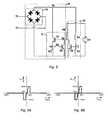
- FIG. 3schematically shows a dimmer triggering circuit according to an embodiment of the invention in more detail
- FIG. 4shows an embodiment of a dimmer triggering circuit as shown in FIGS. 2 and 3 ;
- FIG. 5shows another embodiment of a dimmer triggering circuit as shown in FIGS. 2 and 3 in detail
- FIG. 6Aschematically shows a graph of the voltage-current behavior between terminals of the dimmer triggering circuit of FIG. 4 .
- FIG. 6Bschematically shows a graph of the voltage-current behavior between terminals of an embodiment of a dimmer triggering circuit of FIG. 3 comprising a microprocessor.
- FIG. 1schematically shows a conventional dimmer 1 in connection with an incandescent bulb 3 .
- EMIelectromagnetic interference
- the dimmer 1comprises a TRIAC TR 1 connected in parallel with a variable resistor R 1 and a capacitor C 1 in series.
- the combination of resistor R 1 and capacitor C 1will be referred to as an RC-circuit or timer circuit.
- the dimmercomprises a triggering component, i.e. a component suitable to trigger the TRIAC TR 1 .
- a Diode for Alternating Current (DIAC)is used for this purpose.
- a DIACis a bidirectional trigger-diode that conducts current after a DIAC threshold voltage, also referred to as the DIAC trigger voltage, has been exceeded.
- a DIACremains conducting while the current flowing through it remains above a threshold current. If the current decreases below the threshold current, the DIAC switches back to a high-resistance state.
- the aforementioned characteristicsmake a DIAC very suitable as a trigger switch for a TRIAC.
- the dimmer 1 of FIG. 1comprises a DIAC D 1 , the DIAC D 1 at a first end being connected between the variable resistor R 1 and the capacitor C 1 , and at a second end being connected to the gate of the TRIAC TR 1 .
- the dimmer 1has two terminals, i.e. terminals T 1 and T 2 .
- a series connection of the dimmer 1 and its load 3is connected to an AC voltage source.
- the TRIAC TR 1turns off when the current through the TRIAC TR 1 falls below its threshold value. Once the first zero-crossing has passed, the RC circuit will ‘see’ the actual AC source voltage and will charge up C 1 . Note that this charging current also flows through the incandescent bulb 3 . Once the voltage across C 1 reaches the trigger voltage of the DIAC D 1 , DIAC D 1 starts conducting, and supplies current to the gate of TR 1 while discharging capacitor C 1 . As a result, the TRIAC TR 1 is triggered and turns on. A current starts running through the TRIAC TR 1 . As a result, C 1 is not charged anymore.
- the time needed to reach the DIAC trigger voltage across C 1can be set.
- a higher value of resistor R 1will result in a longer time needed to reach the DIAC trigger voltage on C 1 , and therefore in a shorter conduction interval of the TRIAC TR 1 . It will be understood that by adjusting the time in which current is flowing through the TRIAC TR 1 , the power applied to the light bulb 3 , and thus its illumination intensity, can be adjusted.
- Dimmers like dimmer 1 in FIG. 1function properly if they are used to dim a light source with a sufficient load. That is, after a zero crossing the current supplied through the load needs to be sufficiently high to enable recharging of the capacitor C 1 in the RC-circuit. If not, the TRIAC TR 1 can no longer be triggered and dimming will not occur.
- Loadssuch as an incandescent light bulb of sufficient power provide a current path for charging the RC circuit, a prerequisite for proper functioning of dimmer 1 .
- a well-known example of a low-load applicationis a power-electronic circuit driving a light-source consisting of one or more light emitting diodes (LED) that require DC current.
- LEDlight emitting diodes
- embodiments of the inventionwill be clarified further in combination with a LED-circuit.
- embodiments of the inventionmay also be used in combination with other low-load or discontinuous load applications, i.e. applications unable to provide the necessary charging current for the dimmer's timer circuit to enable proper functioning of a dimmer like dimmer 1 schematically shown in FIG. 1 .
- Loads that have a rectifier front-end with a smoothing capacitorcan be considered to be discontinuous load applications.
- FIG. 2schematically shows a dimmer system 10 according to an embodiment of the invention connected to a LED-circuit 13 .
- the dimmer systemcomprises a dimmer 11 , and a dimmer triggering circuit (DTC) 12 .
- DTCdimmer triggering circuit
- the dimmer 11comprises a first terminal for connection to a terminal T 1 of an alternating current supply and a second terminal for connection to a terminal of a dimmable electrical application, e.g. terminal T 2 of LED-circuit 13 .
- the DTC 12comprises a third terminal, in FIG. 2 connected to the second terminal of the dimmer 11 and a fourth terminal for connection to a further terminal of the alternating circuit supply, i.e. terminal T 3 . Additionally, in FIG. 2 , the fourth terminal is connected to a further terminal of the dimmable electrical application, i.e. LED-circuit 13 .
- the DTC 12is connected in series to the second terminal of the dimmer 11 and in parallel with the LED-circuit 13 .
- the combination of the DTC 12 and a dimmable electrical application like LED-circuit 13may be referred to as a dimmable device.
- FIG. 3schematically shows the DTC 12 in more detail.
- the DTC 12comprises a voltage-level detector 15 and a bipolar current source circuit 18 .
- the voltage-level detector 15is arranged to detect whether the absolute value of the voltage at terminal T 2 is below a threshold value.
- the bipolar current source circuit 18is arranged to be activated if the voltage detected by the voltage level detector 15 remains below the threshold value and to be deactivated otherwise. Therefore, the bipolar current source circuit 18 in the DTC 12 is a voltage-dependent current source, and the DTC 12 as a whole can be considered to act as a bipolar voltage-dependent current source. As will be explained in more detail below, such a DTC 12 dissipates an average power less than 100 mW.
- the DTC 12may dissipate an average power of 10-50 mW.
- the dissipation of the DTC 12is about 30 mW. With such a dissipation most conventional dimmers are able to operate as intended.
- the voltage-level detector 15may comprise a microprocessor.
- the microprocessoris then arranged for detecting whether an absolute value of an input voltage of the dimmer triggering circuit 12 is below a threshold value. If the input voltage of the dimmer triggering circuit 12 is below the threshold value, the microprocessor may instruct the bipolar current source circuit 18 to provide a current. In embodiments of the invention, as will be explained in more detail with reference to FIG. 5B , the microprocessor may instruct the bipolar current source circuit 18 to provide the current after passage of the zero crossing.
- the voltage-level detector 15comprises a comparator for detecting whether an absolute value of an input voltage of the dimmer triggering circuit is below the threshold value.
- the comparatorcomprises two inputs and a single output as schematically shown in FIG. 4 .
- a first inputis connected to a reference potential, i.e. a potential equal to the threshold value, in this example 30V.
- a second inputis arranged to receive the input voltage of the dimmer triggering circuit 12 . If the input voltage of the dimmer triggering circuit 12 at the second input of the comparator is below the threshold value at the first input of the comparator, the output of the comparator may be such that the bipolar current source circuit 18 provides a current as discussed above.
- an operational amplifiercan be used as will be understood by a person skilled in the art.
- the bipolar current source circuit 18comprises a current source circuit 17 and a rectifier 19 .
- the current source circuit 17is coupled to the voltage-level detector 15 .
- both the voltage-level detector 15 and the current source circuit 17are connected to the DC terminals of rectifier 19 .
- the rectifier 19 in the DTC 12 of FIG. 3has an AC-side, i.e. terminals connected to terminals T 2 and T 3 respectively, and a DC-side, i.e. terminals connected to a reference potential and the other components in the DTC 12 like the voltage-level detector 15 and the current source circuit 17 in the bipolar current source circuit 18 .
- the voltage-level detector 15 and current source circuit 17form a unipolar circuit.
- the rectifier 19is arranged to enable the current generated by the current source circuit 17 to be supplied as a bipolar current to the dimmer 11 .
- the DTC 12forces the dimmer 11 to work as if it was loaded by a normal incandescent lamp. If the AC-voltage is sufficiently low, i.e. below the aforementioned threshold value, the DTC 12 is activated and enables sufficient current to flow into the RC-circuit of the dimmer 11 . Note that as the voltage-level detector 15 in the embodiment of FIG. 3 is located at the DC-side of the rectifier 19 , only an absolute threshold value is needed. This means that if the threshold value is 30V, the DTC 12 is activated in the range ⁇ 30V to +30V.
- the threshold valuewhen used in connection with a mains power system of 230 V and 50 Hz, lies between 3 V and 50 V. In other embodiments of the DTC 12 the minimal threshold value is 10V. In case the DTC 12 is connected to a mains power system of 120 V and 60 Hz, as used in the United States, the threshold value may lie between 3V and 25 V.
- the average rectified voltage measured with the voltage-level detector 15may be used as a set point for current through the low-load application, e.g. a LED-circuit 13 as schematically depicted in FIG. 3 .
- Thisenables further optimization of dimming of the low-load application.
- LED-illuminationsuch optimization may result in setting an intensity range of dimming different from 0-100% of the LEDs maximum light intensity, e.g. 30-80%.
- optimizationmay take the form of more sensitive dimming in low light-intensity regions, i.e. 1-10% within the set light intensity range, and less sensitive dimming in high light intensity regions, e.g. 10-100% within the set light intensity range.
- the current provided by the DTC 12keeps the load voltage effectively zero until the TRIAC in the dimmer 11 is triggered, e.g. as schematically shown in FIG. 1 with respect to TRIAC TR 1 being triggered by DIAC D 1 . As soon as the TRIAC switches on, the voltage at terminal T 2 increases by a large amount. As a result, the current source circuit 17 in the DTC 12 is deactivated.
- the DTC 12only conducts current when the voltage at T 2 exceeds a threshold value and behaves like an open circuit otherwise.
- the DTC 12will provide current while being deactivated.
- the current provided by the current source circuit 17 in the DTC 12 at deactivationis negligible.
- a currentmay be considered to be negligible if the current is at least two orders of magnitude smaller than the maximum current the current source circuit 17 of the DTC 12 can provide. So, for example, if the maximum current to be provided by the current source circuit 17 in the DTC 12 is 15 mA, a current is considered to be negligible if its value remains below 100 ⁇ A.
- the DTC 12acts complementarily to the state of the TRIAC in the dimmer 11 . That is, if the DTC 12 is on, the TRIAC in the dimmer 11 is off, and vice versa.
- both the DTC 12 and the TRIAC in the dimmer 11may be on at the same time. That is until the DTC 12 shuts off when the input voltage of the DTC 12 exceeds the threshold value described earlier. In such a case, the DTC 12 and the TRIAC in the dimmer 11 do not act complementarily. For a fraction of a millisecond, power is dissipated. This dissipated power will be negligible though. For example, for a threshold value of 20V and a current source circuit 17 arranged to provide a current of 15 mA the peak power will not exceed 0.3 W and the average power will not exceed 30 mW.
- the TRIACturns off (in case it was still on), while the DTC 12 remains on.
- the DTC 12turns off.
- the DTC 12is arranged to supply a current when the absolute voltage at T 2 is below a threshold value. This current only needs to be sufficient to enable recharging of the capacitor in the RC-circuit of the dimmer and has no relation to the TRIAC's holding current or minimum load of the dimmer in question.
- Thisprovides the benefit that the DTC 12 can also be used in combination with a TRIAC having a holding current larger than the maximum current to be provided by the DTC 12 .
- a dimmer 11comprising a TRIAC with a holding current larger than 15 mA, e.g. 100 mA, can be used to enable dimming of low load applications.
- the capacitance at the AC-side of the rectifier 19is preferably minimized, as will be understood by a person skilled in the art.
- no additional capacitanceis present between T 2 and T 3 .
- the LED-circuit 13generally comprises, besides one or more LEDs, a rectifier and one or more smoothing capacitors.
- the DTC 12may be used to provide a method for triggering a dimmer in an alternating current circuit. Such a method would comprise detecting whether an absolute value of an input voltage of the DTC is below a threshold value. Subsequently, a current is provided by means of a current source circuit if the voltage detected is below the threshold value. If the voltage detected is not below the threshold value, no current is provided. The current provided from the current source circuit is then provided to the dimmer.
- the aforementioned input voltagemay be generated by rectifying an alternating voltage of the alternating current circuit. Subsequently or alternatively, the input voltage may be converted into a voltage suitable for detection. Finally, the current provided by the current source circuit may be limited.
- FIG. 5shows another embodiment of a DTC like DTC 12 shown in FIGS. 2 and 3 in detail. It must be understood that this embodiment merely serves as an example of a possible implementation of the invention. As a skilled person will know, many implementations are possible. For example, instead of bipolar NPN-transistors other switches like bipolar PNP-transistors, Integrated-Gate Bipolar Transistors (IGBTs) or Metal-Oxide-Semiconductor Field-Effect Transistors (MOSFETs) may be used.
- IGBTsIntegrated-Gate Bipolar Transistors
- MOSFETsMetal-Oxide-Semiconductor Field-Effect Transistors
- the bipolar current source circuit 18again comprises a current source circuit 17 and a rectifier 19 .
- the rectifier 19comprises a rectifying diode bridge.
- the current source circuit 17comprises two resistors R 2 , R 3 and two NPN-transistors Q 1 , Q 2 .
- the voltage-level detector 15comprises an NPN-transistor Q 3 and two resistors R 4 and R 5 .
- a DC voltage source V 1is connected to the collector of transistor Q 3 of the voltage-level detector 15 .
- Resistor R 6is chosen such that a desirable base current may be applied to Q 1 when Q 3 is off.
- the DC voltage source V 1may be an external source. It must be understood that, in order to obtain the aforementioned desirable base current, instead of a DC voltage source V 1 and a resistor R 6 , also a current source may be used.
- Resistors R 4 and R 5form a voltage-divider designed such that if the voltage at T 4 is below aforementioned threshold value, the voltage at T 7 is such that Q 3 is off.
- the collector of Q 1 in this particular embodiment of the current source circuit 17is connected to the terminal of the rectifying diode bridge denoted as T 4 .
- the base of Q 1is connected to the collector of Q 2 , and also to the collector of Q 3 in the voltage-level detector 15 .
- the voltage at T 4is below aforementioned threshold value, Q 3 is off, and R 6 will now provide current to the base of Q 1 .
- the voltage at T 6increases such that Q 1 turns on.
- Q 1conducts current and voltage at T 4 decreases even more, depending on the impedance of the source, which results in an even lower voltage at T 7 . Consequently, the switch-off time of Q 3 is limited.
- Resistors R 2 and R 3are used to design a current source with suitable characteristics, i.e. that transistor Q 2 starts conducting if the emitter current through transistor Q 1 exceeds a certain value, e.g. a nominal current in the range from 10 to 20 mA. Hence, the combination of transistor Q 2 and resistors R 2 and R 3 provide a feedback circuit which effectively limits the collector current of transistor Q 1 .
- the combination of transistors Q 1 , Q 2 and resistors R 2 , R 3form a stable current source circuit 17 for voltages T 4 higher than approximately 1V with respect to the negative terminal of the rectifier 19 .
- the collector currentwill reduce.
- the current source circuit 17is activated when the voltage-level detector 15 detects that the voltage at T 4 becomes lower than a predetermined threshold value and deactivated when the voltage at T 4 rises again above a predetermined threshold value.
- FIG. 6Aschematically shows a graph of the calculation of behavior of current I DTC , i.e. the current through a DTC, as a function of voltage V DTC , i.e. the voltage across the DTC.
- the DTC of FIG. 4is used in which the aforementioned typical values are used for the respective components. Consequently, the DTC is arranged to supply a maximum current with an absolute value of 15 mA if the voltage across the DTC becomes lower than a threshold value of 30V. Due to the rectifier, the current may be supplied to the dimmer in opposite directions.
- I DTCequals zero when V DTC is close to zero, and at a certain value of V DTC rises quickly to the design current, in this case an I DTC of no more than 15 mA. for the low current near zero V DTC is due to the fact that at low voltage, the current source circuit 17 only supplies current on demand, i.e. the dimmer 11 only needs limited current to charge up its timer circuit.
- the shape of the curve shown in FIG. 5which relates to the current source circuit 17 schematically depicted in FIG. 4 , is the result of transistor Q 1 being in saturation at low voltages.
- FIG. 6Bschematically shows a graph of the voltage-current behavior between terminals of an embodiment of a dimmer triggering circuit of FIG. 3 comprising a microprocessor.
- the DTC 12may be switched on while the TRIAC in the dimmer 11 may also be on at the same time.
- the microprocessormay be programmed in such a way that it will only allow the bipolar current source circuit 18 to be active after passage of the zero crossing.
- the voltage-current behavior between terminals of the DTC 12becomes as schematically shown in FIG. 6B .
- the I DTCexperiences a kind of hysteresis. That is, the value of I DTC at a certain V DTC depends on former values of V DTC .
- the parts in the graph for which I DTC is independent of past values of V DTChas been schematically illustrated by the gray line.
- the parts in the graph for which I DTC depends on past values of V DTChas been schematically illustrated by the black line.
- the arrowsdenote the direction of change of V DTC .
- baseused herein should be broadly interpreted as not only referring to connections to a bipolar transistor. They may also refer to similar connections, i.e. “gate”, “drain” and “source” respectively, in case other types of transistors like MOSFETs are used.
- two DTCs with a half wave rectifiermay be used instead of using a DTC with a full wave rectifier like a diode rectifier bridge.
- two DTCs with a half wave rectifiermay be used instead of using a DTC with a full wave rectifier like a diode rectifier bridge.
- one DTCwill be used for one direction of the AC-current, and the other DTC will be used in the opposite direction.
- inventionshave been described with respect to a DTC.
- the inventionmay also relate to a circuit for providing a predetermined current to an alternating current circuit when an input voltage is below a predetermined value, which operates in a similar way as the DTC described above.
- the inventionmay also relate to a method for providing a predetermined current to an alternating current circuit when an input voltage is below a predetermined value.
- the methodthen comprises detecting whether an absolute value of an input voltage of the alternating current circuit is below a threshold value, providing a current by means of a current source circuit if the voltage detected is below the threshold value and not providing a current otherwise and providing the current from the current source circuit to the alternating current circuit.
Landscapes
- Circuit Arrangement For Electric Light Sources In General (AREA)
Abstract
Description
- a voltage-level detector for detecting whether an absolute value of an input voltage of the dimmer triggering circuit is below a threshold value; and
- a current source circuit for providing a current if the voltage detected by the voltage-level detector is below the threshold value and to be deactivated otherwise;
wherein the dimmer triggering circuit, in operation, dissipates an average power less than 100 mW. In an embodiment, the dimmer triggering circuit, in operation, dissipates an average power of 10-50 mW.
- a detection circuit; and
- a voltage dividing circuit for converting the input voltage into a voltage suitable for detection by the detection circuit.
- a dimmer comprising a first terminal for connection to a terminal of an alternating current power supply and a second terminal for connection to a terminal of a dimmable electrical application to be dimmed;
- a dimmer triggering circuit as mentioned above, the dimmer triggering circuit further comprising a third terminal connected to the second terminal, and a fourth terminal for connection to a further terminal of the alternating current power supply and to a further terminal of the dimmable electrical application.
- a dimmer triggering circuit as mentioned above;
- a dimmable electrical application;
wherein the dimmer triggering circuit and the dimmable electrical application are coupled in parallel and the dimmable device is connectable in series to a dimmer. The dimmable electrical application may comprise a light emitting diode.
- detecting whether an absolute value of an input voltage of the dimmer triggering circuit is below a threshold value;
- providing a current by means of a bipolar current source circuit if the voltage detected is below the threshold value and not providing a current otherwise;
- providing the current from the bipolar current source circuit to the dimmer.
Claims (30)
Priority Applications (8)
| Application Number | Priority Date | Filing Date | Title |
|---|---|---|---|
| US12/146,512US8212494B2 (en) | 2008-04-04 | 2008-06-26 | Dimmer triggering circuit, dimmer system and dimmable device |
| EP09728346AEP2277355A1 (en) | 2008-04-04 | 2009-04-03 | Dimmer triggering circuit, dimmer system and dimmable device |
| CN200980121068.2ACN102057752B (en) | 2008-04-04 | 2009-04-03 | Dimmer circuit, dimmer system and dimmable device |
| KR1020107024814AKR20100136536A (en) | 2008-04-04 | 2009-04-03 | Dimmer Triggering Circuits, Dimmer Systems, and Dimmable Devices |
| PCT/EP2009/054011WO2009121956A1 (en) | 2008-04-04 | 2009-04-03 | Dimmer triggering circuit, dimmer system and dimmable device |
| JP2011502393AJP5584919B2 (en) | 2008-04-04 | 2009-04-03 | Dimmer trigger circuit, dimming system and dimmable device |
| TW098111341ATWI452938B (en) | 2008-04-04 | 2009-04-06 | Dimmer triggering circuit, dimmer system and dimmable device |
| US12/575,272US8829812B2 (en) | 2008-04-04 | 2009-10-07 | Dimmable lighting system |
Applications Claiming Priority (2)
| Application Number | Priority Date | Filing Date | Title |
|---|---|---|---|
| US4228908P | 2008-04-04 | 2008-04-04 | |
| US12/146,512US8212494B2 (en) | 2008-04-04 | 2008-06-26 | Dimmer triggering circuit, dimmer system and dimmable device |
Related Child Applications (1)
| Application Number | Title | Priority Date | Filing Date |
|---|---|---|---|
| US12/575,272Continuation-In-PartUS8829812B2 (en) | 2008-04-04 | 2009-10-07 | Dimmable lighting system |
Publications (2)
| Publication Number | Publication Date |
|---|---|
| US20090251059A1 US20090251059A1 (en) | 2009-10-08 |
| US8212494B2true US8212494B2 (en) | 2012-07-03 |
Family
ID=39683198
Family Applications (1)
| Application Number | Title | Priority Date | Filing Date |
|---|---|---|---|
| US12/146,512Active2031-01-31US8212494B2 (en) | 2008-04-04 | 2008-06-26 | Dimmer triggering circuit, dimmer system and dimmable device |
Country Status (8)
| Country | Link |
|---|---|
| US (1) | US8212494B2 (en) |
| EP (1) | EP2277355A1 (en) |
| JP (1) | JP5584919B2 (en) |
| KR (1) | KR20100136536A (en) |
| CN (1) | CN102057752B (en) |
| GB (1) | GB0811713D0 (en) |
| TW (1) | TWI452938B (en) |
| WO (1) | WO2009121956A1 (en) |
Cited By (20)
| Publication number | Priority date | Publication date | Assignee | Title |
|---|---|---|---|---|
| US20100060204A1 (en)* | 2008-09-10 | 2010-03-11 | Toshiba Lighting & Technology Corporation | Power supply unit having dimmer function and lighting unit |
| US20100270935A1 (en)* | 2009-04-24 | 2010-10-28 | Toshiba Lighting & Technology Corporation | Light-emitting device and illumination apparatus |
| US20100289426A1 (en)* | 2009-05-12 | 2010-11-18 | Toshiba Lighting & Technology Corporation | Illumination device |
| US20110043121A1 (en)* | 2009-08-21 | 2011-02-24 | Toshiba Lighting & Technology Corporation | Lighting circuit and illumination device |
| US20110057564A1 (en)* | 2009-09-04 | 2011-03-10 | Toshiba Lighting & Technology Corporation | Led lighting device and illumination apparatus |
| US20110057578A1 (en)* | 2009-09-04 | 2011-03-10 | Toshiba Lighting & Technology Corporation | Led lighting device and illumination apparatus |
| US20110057576A1 (en)* | 2008-03-24 | 2011-03-10 | Hirokazu Otake | Power supply device and lighting equipment |
| US20110074306A1 (en)* | 2009-09-30 | 2011-03-31 | Huiyang Technology Co., Ltd. | Led dimming apparatus, circuit, and method thereof |
| US20110156612A1 (en)* | 2009-12-25 | 2011-06-30 | Sharp Kabushiki Kaisha | Led drive circuit, phase control dimmer, led illumination fixture, led illumination device, and led illumination system |
| US20120229052A1 (en)* | 2011-03-08 | 2012-09-13 | Ching-Nan Yang | Automatic lighting system |
| US9006987B2 (en) | 2012-05-07 | 2015-04-14 | Lighting Science Group, Inc. | Wall-mountable luminaire and associated systems and methods |
| US9185783B2 (en) | 2011-05-15 | 2015-11-10 | Lighting Science Group Corporation | Wireless pairing system and associated methods |
| US9303825B2 (en) | 2013-03-05 | 2016-04-05 | Lighting Science Group, Corporation | High bay luminaire |
| US9402294B2 (en) | 2012-05-08 | 2016-07-26 | Lighting Science Group Corporation | Self-calibrating multi-directional security luminaire and associated methods |
| US9420240B2 (en) | 2011-05-15 | 2016-08-16 | Lighting Science Group Corporation | Intelligent security light and associated methods |
| US9420650B2 (en)* | 2014-11-28 | 2016-08-16 | LSC Lighting Systems (Aust) Pty. Ltd. | Circuitry for LED light dimmer |
| US9608507B2 (en) | 2013-06-14 | 2017-03-28 | Sinope Technologies Inc. | Low power and low EMI power stealing circuit for a control device |
| US9648284B2 (en) | 2011-05-15 | 2017-05-09 | Lighting Science Group Corporation | Occupancy sensor and associated methods |
| KR20190061662A (en) | 2017-11-28 | 2019-06-05 | 다이텍연구원 | Preparation method of quasi-isotropic chopped prepreg sheet and composite materials formed using the same for shock absorption and damping effect |
| US10801714B1 (en) | 2019-10-03 | 2020-10-13 | CarJamz, Inc. | Lighting device |
Families Citing this family (87)
| Publication number | Priority date | Publication date | Assignee | Title |
|---|---|---|---|---|
| US8232742B2 (en) | 2008-11-27 | 2012-07-31 | Arkalumen Inc. | Method, apparatus and computer-readable media for controlling lighting devices |
| US9232591B2 (en) | 2008-12-12 | 2016-01-05 | O2Micro Inc. | Circuits and methods for driving light sources |
| US8339067B2 (en)* | 2008-12-12 | 2012-12-25 | O2Micro, Inc. | Circuits and methods for driving light sources |
| CN102014540B (en)* | 2010-03-04 | 2011-12-28 | 凹凸电子(武汉)有限公司 | Drive circuit and controller for controlling electric power of light source |
| US8508150B2 (en)* | 2008-12-12 | 2013-08-13 | O2Micro, Inc. | Controllers, systems and methods for controlling dimming of light sources |
| US8330388B2 (en)* | 2008-12-12 | 2012-12-11 | O2Micro, Inc. | Circuits and methods for driving light sources |
| US8378588B2 (en) | 2008-12-12 | 2013-02-19 | O2Micro Inc | Circuits and methods for driving light sources |
| US9253843B2 (en) | 2008-12-12 | 2016-02-02 | 02Micro Inc | Driving circuit with dimming controller for driving light sources |
| US9030122B2 (en) | 2008-12-12 | 2015-05-12 | O2Micro, Inc. | Circuits and methods for driving LED light sources |
| US9386653B2 (en) | 2008-12-12 | 2016-07-05 | O2Micro Inc | Circuits and methods for driving light sources |
| US8076867B2 (en) | 2008-12-12 | 2011-12-13 | O2Micro, Inc. | Driving circuit with continuous dimming function for driving light sources |
| US8044608B2 (en) | 2008-12-12 | 2011-10-25 | O2Micro, Inc | Driving circuit with dimming controller for driving light sources |
| US8358085B2 (en) | 2009-01-13 | 2013-01-22 | Terralux, Inc. | Method and device for remote sensing and control of LED lights |
| US9326346B2 (en) | 2009-01-13 | 2016-04-26 | Terralux, Inc. | Method and device for remote sensing and control of LED lights |
| US20100277067A1 (en)* | 2009-04-30 | 2010-11-04 | Lighting Science Group Corporation | Dimmable led luminaire |
| US9155138B2 (en) | 2009-06-25 | 2015-10-06 | Koninklijke Philips N.V. | Driver for cooperating with a wall dimmer |
| TW201129253A (en)* | 2009-10-07 | 2011-08-16 | Lemnis Lighting Patent Holding B V | Dimmable lighting system |
| CN102598856B (en)* | 2009-10-14 | 2015-04-01 | 特里多尼克英国有限公司 | Phase cut dimming of LEDs |
| CN102598857B (en)* | 2009-10-14 | 2015-05-20 | 特里多尼克英国有限公司 | Phase cut dimming of LEDs |
| WO2011045057A1 (en)* | 2009-10-14 | 2011-04-21 | Tridonic Uk Limited | Method for controlling the brightness of an led |
| US20120274216A1 (en)* | 2009-10-30 | 2012-11-01 | Koninklijke Philips Electronics, N.V. | Selectively activated rapid start/bleeder circuit for solid state lighting system |
| DE102009051968B4 (en)* | 2009-11-04 | 2013-02-21 | Insta Elektro Gmbh | Method for transmitting control information from a control unit to a lamp unit, a suitable lighting system, and lamp unit |
| CN102062376A (en)* | 2009-11-13 | 2011-05-18 | 台达电子工业股份有限公司 | LED Lamps and LED Lamp Groups |
| TW201117643A (en)* | 2009-11-13 | 2011-05-16 | Delta Electronics Inc | LED lamp and LED lamp module |
| CA2781077A1 (en) | 2009-11-17 | 2012-06-28 | Terralux, Inc. | Led power-supply detection and control |
| EP2348793A1 (en)* | 2010-01-20 | 2011-07-27 | ATLAS Elektronik GmbH | Illuminant with LED and driver switch |
| US20110181190A1 (en)* | 2010-01-22 | 2011-07-28 | Chiu-Min Lin | Brightness adjusting circuit for an led lamp |
| WO2011100803A1 (en)* | 2010-02-18 | 2011-08-25 | Clipsal Australia Pty Ltd | Control signal generator for a dimmer circuit |
| DE102010000533B4 (en)* | 2010-02-24 | 2011-12-01 | Insta Elektro Gmbh | Control unit for transmitting control information to a lamp unit and method for operating such a control unit |
| CN103391006A (en) | 2012-05-11 | 2013-11-13 | 凹凸电子(武汉)有限公司 | Light source driving circuit and controller and method for controlling power converter |
| US8698419B2 (en) | 2010-03-04 | 2014-04-15 | O2Micro, Inc. | Circuits and methods for driving light sources |
| JP5031865B2 (en)* | 2010-03-23 | 2012-09-26 | シャープ株式会社 | LED drive circuit, LED illumination lamp, LED illumination device, and LED illumination system |
| DE102010028230A1 (en)* | 2010-04-27 | 2011-10-27 | Tridonic Jennersdorf Gmbh | Circuit arrangement for operating LEDs |
| US9086435B2 (en) | 2011-05-10 | 2015-07-21 | Arkalumen Inc. | Circuits for sensing current levels within a lighting apparatus incorporating a voltage converter |
| US8624523B2 (en)* | 2010-05-11 | 2014-01-07 | Arkalumen Inc. | Control apparatus with calibration functionality and lighting apparatus incorporating control apparatus |
| US8564214B2 (en) | 2010-05-11 | 2013-10-22 | Arkalumen Inc. | Circuits for sensing current levels within lighting apparatus |
| US9089024B2 (en) | 2010-05-11 | 2015-07-21 | Arkalumen Inc. | Methods and apparatus for changing a DC supply voltage applied to a lighting circuit |
| US8294377B2 (en)* | 2010-06-25 | 2012-10-23 | Power Integrations, Inc. | Power converter with compensation circuit for adjusting output current provided to a constant load |
| US20120007508A1 (en)* | 2010-07-09 | 2012-01-12 | Chiu-Min Lin | Led lamp brightness adjusting circuit connectable to ac power and led lighting device using the same |
| EP2405717A1 (en)* | 2010-07-09 | 2012-01-11 | Chiu-Min Lin | LED lamp brightness adjusting circuit connectable to AC power and LED lighting device using the same |
| US8111017B2 (en) | 2010-07-12 | 2012-02-07 | O2Micro, Inc | Circuits and methods for controlling dimming of a light source |
| WO2012016716A1 (en)* | 2010-08-06 | 2012-02-09 | Tridonic Uk Ltd. | Led dimming control |
| CN102404899B (en)* | 2010-09-10 | 2015-07-01 | 奥斯兰姆有限公司 | Method and device for controlling effuser connected to cutting phase dimmer |
| US8659232B2 (en) | 2010-09-14 | 2014-02-25 | Crs Electronics | Variable-impedance load for LED lamps |
| CA2810026A1 (en) | 2010-09-16 | 2012-03-22 | Terralux, Inc. | Communication with lighting units over a power bus |
| US9596738B2 (en) | 2010-09-16 | 2017-03-14 | Terralux, Inc. | Communication with lighting units over a power bus |
| PT2456285T (en) | 2010-11-17 | 2017-01-31 | Silergy Corp | A method of controlling an electronic ballast, an electronic ballast and a lighting controller |
| US9192009B2 (en) | 2011-02-14 | 2015-11-17 | Arkalumen Inc. | Lighting apparatus and method for detecting reflected light from local objects |
| US8941308B2 (en) | 2011-03-16 | 2015-01-27 | Arkalumen Inc. | Lighting apparatus and methods for controlling lighting apparatus using ambient light levels |
| US8939604B2 (en) | 2011-03-25 | 2015-01-27 | Arkalumen Inc. | Modular LED strip lighting apparatus |
| CN102791054B (en) | 2011-04-22 | 2016-05-25 | 昂宝电子(上海)有限公司 | For the system and method for the brightness adjustment control under capacity load |
| US9060400B2 (en) | 2011-07-12 | 2015-06-16 | Arkalumen Inc. | Control apparatus incorporating a voltage converter for controlling lighting apparatus |
| US9055633B2 (en)* | 2011-08-24 | 2015-06-09 | Maxim Integrated Products, Inc. | Load compensation for an electronic transformer in a LED illumination system |
| US9380656B2 (en) | 2011-09-06 | 2016-06-28 | Koninklijke Philips N.V. | Power control unit and method for controlling electrical power provided to a load, in particular an LED unit, and voltage control unit for controlling an output voltage of a converter unit |
| RU2611427C2 (en) | 2011-11-04 | 2017-02-22 | Филипс Лайтинг Холдинг Б.В. | Control device and method of load control with polarity-dependent voltage divider circuit |
| WO2013090904A1 (en) | 2011-12-16 | 2013-06-20 | Terralux, Inc. | System and methods of applying bleed circuits in led lamps |
| US9544966B2 (en) | 2012-02-01 | 2017-01-10 | Philips Lighting Holding B.V. | Driver device and driving method for driving a load, in particular a LED unit |
| CN104768285B (en) | 2012-05-17 | 2017-06-13 | 昂宝电子(上海)有限公司 | System and method for carrying out brightness adjustment control using system controller |
| KR102048795B1 (en)* | 2012-08-30 | 2019-11-26 | 휴렛-팩커드 디벨롭먼트 컴퍼니, 엘.피. | Discharging circuit, image forming apparatus having discharging circuit and power supplying unit |
| CN103024994B (en) | 2012-11-12 | 2016-06-01 | 昂宝电子(上海)有限公司 | Use dimming control system and the method for TRIAC dimmer |
| CN103066983A (en)* | 2012-12-16 | 2013-04-24 | 华南理工大学 | Current absolute value circuit and drive method thereof |
| US8981668B2 (en)* | 2013-03-08 | 2015-03-17 | LT Lighting (Taiwan) Corp. | Demand-side initiated dimmable LED lamp |
| WO2014184326A2 (en)* | 2013-05-17 | 2014-11-20 | Koninklijke Philips N.V. | Driver device and driving method for driving a load, in particular an led unit |
| US9265119B2 (en) | 2013-06-17 | 2016-02-16 | Terralux, Inc. | Systems and methods for providing thermal fold-back to LED lights |
| EP2890220B1 (en)* | 2013-12-24 | 2023-10-25 | Silergy Semiconductor (Hong Kong) Limited | Bleeder circuit controller |
| CN103957634B (en) | 2014-04-25 | 2017-07-07 | 广州昂宝电子有限公司 | Lighting system and control method thereof |
| CN104066254B (en) | 2014-07-08 | 2017-01-04 | 昂宝电子(上海)有限公司 | TRIAC dimmer is used to carry out the system and method for intelligent dimming control |
| US10225904B2 (en) | 2015-05-05 | 2019-03-05 | Arkalumen, Inc. | Method and apparatus for controlling a lighting module based on a constant current level from a power source |
| US9992836B2 (en) | 2015-05-05 | 2018-06-05 | Arkawmen Inc. | Method, system and apparatus for activating a lighting module using a buffer load module |
| US9992829B2 (en) | 2015-05-05 | 2018-06-05 | Arkalumen Inc. | Control apparatus and system for coupling a lighting module to a constant current DC driver |
| US10568180B2 (en) | 2015-05-05 | 2020-02-18 | Arkalumen Inc. | Method and apparatus for controlling a lighting module having a plurality of LED groups |
| US9775211B2 (en) | 2015-05-05 | 2017-09-26 | Arkalumen Inc. | Circuit and apparatus for controlling a constant current DC driver output |
| US10736187B2 (en) | 2016-02-03 | 2020-08-04 | Lutron Ketra, Llc | Illumination device and method for decoupling power delivered to an LED load from a phase-cut dimming angle |
| CN106413189B (en) | 2016-10-17 | 2018-12-28 | 广州昂宝电子有限公司 | Use the intelligence control system relevant to TRIAC light modulator and method of modulated signal |
| CN107645804A (en) | 2017-07-10 | 2018-01-30 | 昂宝电子(上海)有限公司 | System for LED switch control |
| CN107682953A (en) | 2017-09-14 | 2018-02-09 | 昂宝电子(上海)有限公司 | LED illumination System and its control method |
| CN107995730B (en) | 2017-11-30 | 2020-01-07 | 昂宝电子(上海)有限公司 | System and method for phase-based control associated with TRIAC dimmers |
| TWI698153B (en)* | 2017-12-20 | 2020-07-01 | 美商亮銳公司 | Dimmer switch interface and led light system |
| CN108200685B (en) | 2017-12-28 | 2020-01-07 | 昂宝电子(上海)有限公司 | LED lighting system for thyristor switch control |
| CA3104665A1 (en) | 2018-06-26 | 2020-01-02 | Lutron Technology Company Llc | Load control device having a controllable filter circuit |
| US10816606B2 (en)* | 2019-01-03 | 2020-10-27 | GM Global Technology Operations LLC | Method and system for noise-tolerant RC response prediction |
| CN109922564B (en) | 2019-02-19 | 2023-08-29 | 昂宝电子(上海)有限公司 | Voltage conversion system and method for TRIAC drive |
| CN110493913B (en) | 2019-08-06 | 2022-02-01 | 昂宝电子(上海)有限公司 | Control system and method for silicon controlled dimming LED lighting system |
| CN110831295B (en) | 2019-11-20 | 2022-02-25 | 昂宝电子(上海)有限公司 | Dimming control method and system for dimmable LED lighting system |
| CN110831289B (en) | 2019-12-19 | 2022-02-15 | 昂宝电子(上海)有限公司 | LED drive circuit, operation method thereof and power supply control module |
| CN111031635B (en) | 2019-12-27 | 2021-11-30 | 昂宝电子(上海)有限公司 | Dimming system and method for LED lighting system |
| CN111432526B (en) | 2020-04-13 | 2023-02-21 | 昂宝电子(上海)有限公司 | Control system and method for power factor optimization of LED lighting systems |
Citations (23)
| Publication number | Priority date | Publication date | Assignee | Title |
|---|---|---|---|---|
| US4935691A (en) | 1989-07-12 | 1990-06-19 | Dodge-Romig Research & Development, Incorporated | Phase switched power controller |
| JPH046694A (en) | 1990-04-25 | 1992-01-10 | Hitachi Ltd | Reference voltage generating circuit |
| US5194782A (en) | 1991-07-19 | 1993-03-16 | Richardson Robert H | Dimmer for fluorescent lamp |
| US5872429A (en) | 1995-03-31 | 1999-02-16 | Philips Electronics North America Corporation | Coded communication system and method for controlling an electric lamp |
| WO1999029142A1 (en) | 1997-12-03 | 1999-06-10 | Daysun Electronics Co., Ltd. | Circuit and method for driving light emitting diode |
| EP0991304A2 (en) | 1998-10-02 | 2000-04-05 | TEC Electrical Components Limited | Dimmer circuit for a LED |
| US6127784A (en) | 1998-08-31 | 2000-10-03 | Dialight Corporation | LED driving circuitry with variable load to control output light intensity of an LED |
| US20020017877A1 (en) | 1999-11-17 | 2002-02-14 | Oostvogels Ludovicus F. J. | Ballast circuit |
| US20030080696A1 (en) | 2001-09-06 | 2003-05-01 | Tang Pak Chuen | Phase-controlled dimmable electronic ballasts for fluorescent lamps with very wide dimming range |
| US20040195977A1 (en) | 2003-04-04 | 2004-10-07 | Patent-Treuhand-Gesellschaft Fur Elektrische Gluhlampen Mbh | Interface circuit for operating capacitive loads |
| US20040212321A1 (en) | 2001-03-13 | 2004-10-28 | Lys Ihor A | Methods and apparatus for providing power to lighting devices |
| US20050057179A1 (en)* | 2003-08-27 | 2005-03-17 | Osram Sylvania Inc. | Driver circuit for LED vehicle lamp |
| US20050168168A1 (en) | 2004-02-02 | 2005-08-04 | Stephen Elliott | Light dimmer for LED and incandescent lamps |
| WO2005115058A1 (en) | 2004-05-19 | 2005-12-01 | Goeken Group Corp. | Dimming circuit for led lighting device with means for holding triac in conduction |
| US7102902B1 (en) | 2005-02-17 | 2006-09-05 | Ledtronics, Inc. | Dimmer circuit for LED |
| WO2006120629A2 (en) | 2005-05-09 | 2006-11-16 | Koninklijke Philips Electronics N.V. | Method and circuit for enabling dimming using triac dimmer |
| US7170236B2 (en)* | 2005-06-15 | 2007-01-30 | Osram Sylvania Inc. | Method of setting desired RMS load voltage in a lamp |
| WO2007026170A2 (en) | 2005-09-03 | 2007-03-08 | E-Light Limited | Improvements to lighting systems |
| US20070182338A1 (en) | 2006-01-20 | 2007-08-09 | Exclara Inc. | Current regulator for modulating brightness levels of solid state lighting |
| US20070182347A1 (en) | 2006-01-20 | 2007-08-09 | Exclara Inc. | Impedance matching circuit for current regulation of solid state lighting |
| GB2435724A (en) | 2006-03-04 | 2007-09-05 | Mood Concepts Ltd | TRIAC dimming of LED lighting units |
| WO2008029108A1 (en) | 2006-09-04 | 2008-03-13 | Lutron Electronics Co., Inc. | Variable load circuits for use with lighting control devices |
| US20080180036A1 (en) | 2007-01-31 | 2008-07-31 | Lighting Science Group Corporation | Method and apparatus for operating a light emitting diode with a dimmer |
Family Cites Families (7)
| Publication number | Priority date | Publication date | Assignee | Title |
|---|---|---|---|---|
| JPS57124887A (en)* | 1981-01-27 | 1982-08-03 | Matsushita Electric Works Ltd | Dimming device |
| HK1051122A2 (en)* | 2002-05-24 | 2003-06-27 | Clipsal Asia Holdings Limited | A dimming apparatus especially a dimmer for a compact fluorescent lamp |
| JP2004327152A (en)* | 2003-04-23 | 2004-11-18 | Toshiba Lighting & Technology Corp | LED lighting device and LED lighting equipment |
| JP4235060B2 (en)* | 2003-08-12 | 2009-03-04 | 矢崎総業株式会社 | Pointer device and pointing device |
| JP2006319172A (en)* | 2005-05-13 | 2006-11-24 | Wako Denken Kk | Adapter device for light control of led lamp |
| TWI282252B (en)* | 2005-11-30 | 2007-06-01 | Princeton Technology Corp | Fluorescent lamp lighting adjustment system, control device and method thereof |
| JP4715547B2 (en)* | 2006-02-23 | 2011-07-06 | パナソニック電工株式会社 | LIGHTING POWER CIRCUIT, LIGHTING DEVICE, AND LIGHTING SYSTEM |
- 2008
- 2008-06-26USUS12/146,512patent/US8212494B2/enactiveActive
- 2008-06-26GBGBGB0811713.7Apatent/GB0811713D0/ennot_activeCeased
- 2009
- 2009-04-03WOPCT/EP2009/054011patent/WO2009121956A1/enactiveApplication Filing
- 2009-04-03JPJP2011502393Apatent/JP5584919B2/enactiveActive
- 2009-04-03KRKR1020107024814Apatent/KR20100136536A/ennot_activeCeased
- 2009-04-03EPEP09728346Apatent/EP2277355A1/ennot_activeCeased
- 2009-04-03CNCN200980121068.2Apatent/CN102057752B/enactiveActive
- 2009-04-06TWTW098111341Apatent/TWI452938B/enactive
Patent Citations (24)
| Publication number | Priority date | Publication date | Assignee | Title |
|---|---|---|---|---|
| US4935691A (en) | 1989-07-12 | 1990-06-19 | Dodge-Romig Research & Development, Incorporated | Phase switched power controller |
| JPH046694A (en) | 1990-04-25 | 1992-01-10 | Hitachi Ltd | Reference voltage generating circuit |
| US5194782A (en) | 1991-07-19 | 1993-03-16 | Richardson Robert H | Dimmer for fluorescent lamp |
| US5872429A (en) | 1995-03-31 | 1999-02-16 | Philips Electronics North America Corporation | Coded communication system and method for controlling an electric lamp |
| WO1999029142A1 (en) | 1997-12-03 | 1999-06-10 | Daysun Electronics Co., Ltd. | Circuit and method for driving light emitting diode |
| US6127784A (en) | 1998-08-31 | 2000-10-03 | Dialight Corporation | LED driving circuitry with variable load to control output light intensity of an LED |
| EP0991304A2 (en) | 1998-10-02 | 2000-04-05 | TEC Electrical Components Limited | Dimmer circuit for a LED |
| US20020017877A1 (en) | 1999-11-17 | 2002-02-14 | Oostvogels Ludovicus F. J. | Ballast circuit |
| US20040212321A1 (en) | 2001-03-13 | 2004-10-28 | Lys Ihor A | Methods and apparatus for providing power to lighting devices |
| US20030080696A1 (en) | 2001-09-06 | 2003-05-01 | Tang Pak Chuen | Phase-controlled dimmable electronic ballasts for fluorescent lamps with very wide dimming range |
| US20040195977A1 (en) | 2003-04-04 | 2004-10-07 | Patent-Treuhand-Gesellschaft Fur Elektrische Gluhlampen Mbh | Interface circuit for operating capacitive loads |
| EP1467474A2 (en) | 2003-04-04 | 2004-10-13 | Patent-Treuhand-Gesellschaft für elektrische Glühlampen mbH | Interface circuit for operation of capacitive loads |
| US20050057179A1 (en)* | 2003-08-27 | 2005-03-17 | Osram Sylvania Inc. | Driver circuit for LED vehicle lamp |
| US20050168168A1 (en) | 2004-02-02 | 2005-08-04 | Stephen Elliott | Light dimmer for LED and incandescent lamps |
| WO2005115058A1 (en) | 2004-05-19 | 2005-12-01 | Goeken Group Corp. | Dimming circuit for led lighting device with means for holding triac in conduction |
| US7102902B1 (en) | 2005-02-17 | 2006-09-05 | Ledtronics, Inc. | Dimmer circuit for LED |
| WO2006120629A2 (en) | 2005-05-09 | 2006-11-16 | Koninklijke Philips Electronics N.V. | Method and circuit for enabling dimming using triac dimmer |
| US7170236B2 (en)* | 2005-06-15 | 2007-01-30 | Osram Sylvania Inc. | Method of setting desired RMS load voltage in a lamp |
| WO2007026170A2 (en) | 2005-09-03 | 2007-03-08 | E-Light Limited | Improvements to lighting systems |
| US20070182338A1 (en) | 2006-01-20 | 2007-08-09 | Exclara Inc. | Current regulator for modulating brightness levels of solid state lighting |
| US20070182347A1 (en) | 2006-01-20 | 2007-08-09 | Exclara Inc. | Impedance matching circuit for current regulation of solid state lighting |
| GB2435724A (en) | 2006-03-04 | 2007-09-05 | Mood Concepts Ltd | TRIAC dimming of LED lighting units |
| WO2008029108A1 (en) | 2006-09-04 | 2008-03-13 | Lutron Electronics Co., Inc. | Variable load circuits for use with lighting control devices |
| US20080180036A1 (en) | 2007-01-31 | 2008-07-31 | Lighting Science Group Corporation | Method and apparatus for operating a light emitting diode with a dimmer |
Non-Patent Citations (1)
| Title |
|---|
| Rand D et al: "Issues, Models and Solutions for Triac Modulated Phase Dimming of LED Lamps Power electronics specialists conference 2007, IEEE, Piscataway NJ, USA, Jun. 17, 2007, pp. 1398-1404." |
Cited By (28)
| Publication number | Priority date | Publication date | Assignee | Title |
|---|---|---|---|---|
| US20110057576A1 (en)* | 2008-03-24 | 2011-03-10 | Hirokazu Otake | Power supply device and lighting equipment |
| US8354804B2 (en) | 2008-03-24 | 2013-01-15 | Toshiba Lighting & Technology Corporation | Power supply device and lighting equipment |
| US8513902B2 (en) | 2008-09-10 | 2013-08-20 | Toshiba Lighting & Technology Corporation | Power supply unit having dimmer function and lighting unit |
| US20100060204A1 (en)* | 2008-09-10 | 2010-03-11 | Toshiba Lighting & Technology Corporation | Power supply unit having dimmer function and lighting unit |
| US8643288B2 (en) | 2009-04-24 | 2014-02-04 | Toshiba Lighting & Technology Corporation | Light-emitting device and illumination apparatus |
| US20100270935A1 (en)* | 2009-04-24 | 2010-10-28 | Toshiba Lighting & Technology Corporation | Light-emitting device and illumination apparatus |
| US20100289426A1 (en)* | 2009-05-12 | 2010-11-18 | Toshiba Lighting & Technology Corporation | Illumination device |
| US20110043121A1 (en)* | 2009-08-21 | 2011-02-24 | Toshiba Lighting & Technology Corporation | Lighting circuit and illumination device |
| US8970127B2 (en) | 2009-08-21 | 2015-03-03 | Toshiba Lighting & Technology Corporation | Lighting circuit and illumination device |
| US8427070B2 (en)* | 2009-08-21 | 2013-04-23 | Toshiba Lighting & Technology Corporation | Lighting circuit and illumination device |
| US20110057578A1 (en)* | 2009-09-04 | 2011-03-10 | Toshiba Lighting & Technology Corporation | Led lighting device and illumination apparatus |
| US20110057564A1 (en)* | 2009-09-04 | 2011-03-10 | Toshiba Lighting & Technology Corporation | Led lighting device and illumination apparatus |
| US8610363B2 (en) | 2009-09-04 | 2013-12-17 | Toshiba Lighting & Technology Corporation | LED lighting device and illumination apparatus |
| US20110074306A1 (en)* | 2009-09-30 | 2011-03-31 | Huiyang Technology Co., Ltd. | Led dimming apparatus, circuit, and method thereof |
| US20110156612A1 (en)* | 2009-12-25 | 2011-06-30 | Sharp Kabushiki Kaisha | Led drive circuit, phase control dimmer, led illumination fixture, led illumination device, and led illumination system |
| US20120229052A1 (en)* | 2011-03-08 | 2012-09-13 | Ching-Nan Yang | Automatic lighting system |
| US9420240B2 (en) | 2011-05-15 | 2016-08-16 | Lighting Science Group Corporation | Intelligent security light and associated methods |
| US9185783B2 (en) | 2011-05-15 | 2015-11-10 | Lighting Science Group Corporation | Wireless pairing system and associated methods |
| US9648284B2 (en) | 2011-05-15 | 2017-05-09 | Lighting Science Group Corporation | Occupancy sensor and associated methods |
| US9681108B2 (en) | 2011-05-15 | 2017-06-13 | Lighting Science Group Corporation | Occupancy sensor and associated methods |
| US9006987B2 (en) | 2012-05-07 | 2015-04-14 | Lighting Science Group, Inc. | Wall-mountable luminaire and associated systems and methods |
| US9402294B2 (en) | 2012-05-08 | 2016-07-26 | Lighting Science Group Corporation | Self-calibrating multi-directional security luminaire and associated methods |
| US9303825B2 (en) | 2013-03-05 | 2016-04-05 | Lighting Science Group, Corporation | High bay luminaire |
| US9608507B2 (en) | 2013-06-14 | 2017-03-28 | Sinope Technologies Inc. | Low power and low EMI power stealing circuit for a control device |
| US9420650B2 (en)* | 2014-11-28 | 2016-08-16 | LSC Lighting Systems (Aust) Pty. Ltd. | Circuitry for LED light dimmer |
| KR20190061662A (en) | 2017-11-28 | 2019-06-05 | 다이텍연구원 | Preparation method of quasi-isotropic chopped prepreg sheet and composite materials formed using the same for shock absorption and damping effect |
| US10801714B1 (en) | 2019-10-03 | 2020-10-13 | CarJamz, Inc. | Lighting device |
| US11054127B2 (en) | 2019-10-03 | 2021-07-06 | CarJamz Com, Inc. | Lighting device |
Also Published As
| Publication number | Publication date |
|---|---|
| EP2277355A1 (en) | 2011-01-26 |
| US20090251059A1 (en) | 2009-10-08 |
| KR20100136536A (en) | 2010-12-28 |
| TWI452938B (en) | 2014-09-11 |
| CN102057752A (en) | 2011-05-11 |
| JP5584919B2 (en) | 2014-09-10 |
| WO2009121956A1 (en) | 2009-10-08 |
| GB0811713D0 (en) | 2008-07-30 |
| CN102057752B (en) | 2016-06-08 |
| JP2011517024A (en) | 2011-05-26 |
| TW200945946A (en) | 2009-11-01 |
Similar Documents
| Publication | Publication Date | Title |
|---|---|---|
| US8212494B2 (en) | Dimmer triggering circuit, dimmer system and dimmable device | |
| US8829812B2 (en) | Dimmable lighting system | |
| US7242150B2 (en) | Dimmer having a power supply monitoring circuit | |
| RU2638958C2 (en) | Circuit device and led lamp, containing this circuit device | |
| US8581498B1 (en) | Control of bleed current in drivers for dimmable lighting devices | |
| CN105423140A (en) | Dynamic Bleeder Current Control for LED Dimmers | |
| CN103633826B (en) | Comprise the low current start-up circuit of power switch | |
| CN101516148A (en) | LED drive circuit | |
| JP5822670B2 (en) | LED lighting device | |
| WO2011042510A2 (en) | Dimmable lighting system | |
| CN103975650A (en) | Systems and methods for LED dimmer compatibility | |
| US9730287B2 (en) | Lighting apparatus and dimming regulation circuit thereof | |
| TWI691235B (en) | Dimmer circuit for use in light-emitting diode lighting system | |
| CN110913529B (en) | LED lighting system with automatic bleeder current control | |
| KR102253999B1 (en) | LED dimmer with dimming control function for phase control | |
| CN204986459U (en) | Light emitting diode lamp | |
| US20170127488A1 (en) | Adaptive Power Balancing in LED Lamps | |
| KR100878852B1 (en) | Dimmer of AC drive LED | |
| JP2019207833A (en) | Power supply device for illumination | |
| CN216820146U (en) | Dummy load control circuit for compatible silicon controlled rectifier dimmer and lighting equipment | |
| CN111246619A (en) | LED driver for phase-cut dimmer |
Legal Events
| Date | Code | Title | Description |
|---|---|---|---|
| AS | Assignment | Owner name:LEMNIS LIGHTING PATENT HOLDING B.V., NETHERLANDS Free format text:ASSIGNMENT OF ASSIGNORS INTEREST;ASSIGNOR:VELTMAN, ANDRE, MR.;REEL/FRAME:021663/0827 Effective date:20081010 | |
| STCF | Information on status: patent grant | Free format text:PATENTED CASE | |
| AS | Assignment | Owner name:KONINKLIJKE PHILIPS N.V., NETHERLANDS Free format text:ASSIGNMENT OF ASSIGNORS INTEREST;ASSIGNOR:LEMNIS LIGHTING PATENT HOLDING B.V.;REEL/FRAME:032892/0480 Effective date:20131001 | |
| FPAY | Fee payment | Year of fee payment:4 | |
| AS | Assignment | Owner name:PHILIPS LIGHTING HOLDING B.V., NETHERLANDS Free format text:ASSIGNMENT OF ASSIGNORS INTEREST;ASSIGNOR:KONINKLIJKE PHILIPS N.V.;REEL/FRAME:040060/0009 Effective date:20160607 | |
| FEPP | Fee payment procedure | Free format text:ENTITY STATUS SET TO UNDISCOUNTED (ORIGINAL EVENT CODE: BIG.) | |
| AS | Assignment | Owner name:SIGNIFY HOLDING B.V., NETHERLANDS Free format text:CHANGE OF NAME;ASSIGNOR:PHILIPS LIGHTING HOLDING B.V.;REEL/FRAME:050837/0576 Effective date:20190201 | |
| MAFP | Maintenance fee payment | Free format text:PAYMENT OF MAINTENANCE FEE, 8TH YEAR, LARGE ENTITY (ORIGINAL EVENT CODE: M1552); ENTITY STATUS OF PATENT OWNER: LARGE ENTITY Year of fee payment:8 | |
| MAFP | Maintenance fee payment | Free format text:PAYMENT OF MAINTENANCE FEE, 12TH YEAR, LARGE ENTITY (ORIGINAL EVENT CODE: M1553); ENTITY STATUS OF PATENT OWNER: LARGE ENTITY Year of fee payment:12 |