US8211154B2 - Bone plate assemblies with backout protection and visual indicator - Google Patents
Bone plate assemblies with backout protection and visual indicatorDownload PDFInfo
- Publication number
- US8211154B2 US8211154B2US12/419,012US41901209AUS8211154B2US 8211154 B2US8211154 B2US 8211154B2US 41901209 AUS41901209 AUS 41901209AUS 8211154 B2US8211154 B2US 8211154B2
- Authority
- US
- United States
- Prior art keywords
- tab member
- bushing
- screw
- visual indicator
- protrusion
- Prior art date
- Legal status (The legal status is an assumption and is not a legal conclusion. Google has not performed a legal analysis and makes no representation as to the accuracy of the status listed.)
- Expired - Fee Related, expires
Links
Images


Classifications
- A—HUMAN NECESSITIES
- A61—MEDICAL OR VETERINARY SCIENCE; HYGIENE
- A61B—DIAGNOSIS; SURGERY; IDENTIFICATION
- A61B17/00—Surgical instruments, devices or methods
- A61B17/56—Surgical instruments or methods for treatment of bones or joints; Devices specially adapted therefor
- A61B17/58—Surgical instruments or methods for treatment of bones or joints; Devices specially adapted therefor for osteosynthesis, e.g. bone plates, screws or setting implements
- A61B17/68—Internal fixation devices, including fasteners and spinal fixators, even if a part thereof projects from the skin
- A61B17/80—Cortical plates, i.e. bone plates; Instruments for holding or positioning cortical plates, or for compressing bones attached to cortical plates
- A61B17/8033—Cortical plates, i.e. bone plates; Instruments for holding or positioning cortical plates, or for compressing bones attached to cortical plates having indirect contact with screw heads, or having contact with screw heads maintained with the aid of additional components, e.g. nuts, wedges or head covers
- A61B17/8047—Cortical plates, i.e. bone plates; Instruments for holding or positioning cortical plates, or for compressing bones attached to cortical plates having indirect contact with screw heads, or having contact with screw heads maintained with the aid of additional components, e.g. nuts, wedges or head covers wherein the additional element surrounds the screw head in the plate hole
Definitions
- the present disclosuregenerally relates to spinal implants and associated methods, and more particularly relates to bone plate assemblies having backout protection.
- the vertebrae of the human spineare arranged in a column with one vertebra on top of the next.
- An intervertebral disclies between adjacent vertebrae to transmit force between the adjacent vertebrae and provide a cushion between them.
- the discsallow the spine to flex and twist. With age, spinal discs begin to break down, or degenerate resulting in the loss of fluid in the discs and consequently resulting in them becoming less flexible. Likewise, the disks become thinner allowing the vertebrae to move closer together. Degeneration may also result in tears or cracks in the outer layer, or annulus, of the disc. The disc may begin to bulge outwardly. In more severe cases, the inner material of the disc, or nucleus, may actually extrude out of the disc.
- the spinemay undergo changes due to trauma from automobile accidents, falls, heavy lifting, and other activities.
- spinal stenosisthe spinal canal narrows due to excessive bone growth, thickening of tissue in the canal (such as ligament), or both.
- tissue in the canalsuch as ligament
- the spaces through which the spinal cord and the spinal nerve roots passmay become narrowed leading to pressure on the nerve tissue which can cause pain, numbness, weakness, or even paralysis in various parts of the body.
- the facet joints between adjacent vertebraemay degenerate and cause localized and/or radiating pain. All of the above conditions are collectively referred to herein as spine disease.
- surgeonstreat spine disease by attempting to restore the normal spacing between adjacent vertebrae. This may be sufficient to relieve pressure from affected nerve tissue.
- the restoration of vertebral spacingis accomplished by inserting a rigid spacer made of bone, metal, or plastic into the disc space between the adjacent vertebrae and allowing the vertebrae to grow together, or fuse, into a single piece of bone.
- the vertebraeare typically stabilized during this fusion process with the use of bone plates and/or pedicle screws fastened to the adjacent vertebrae.
- a plurality of bone screwsmay be used to secure a plate to the vertebrae.
- the bone screwsabsent a screw retention mechanism, may back out or reverse thread. Screw retention mechanisms have been developed to inhibit the bone screws from backing out.
- Some of the devicesinclude caps or plates that extend over the screw holes in the plate to inhibit upward movement of bone screws relative to the plate.
- Other devicesinclude a frictional engagement between a bushing and the bone screws.
- a bone plate assemblythat includes a plate, at least one bushing, and at least one bone screw.
- the bushingis positioned within a through hole of the plate.
- the bushing and screware configured to engage each other to inhibit the screw from backing out.
- the screwmay include at least one visual indicator surface that is visible to the operator during insertion of the screw through the bushing and plate.
- the bushingis configured to cover at least a portion of the visual indicator surface to show the operator when the bushing and screw are properly engaged to inhibit backout of the screw.
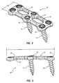
- FIG. 1is a partially exploded perspective view of a bone plate assembly according to the present disclosure
- FIG. 2is a top view of the bone plate assembly of FIG. 1 including two screws and two bushing members;
- FIG. 3is a side view of the bone plate assembly of FIG. 2 ;
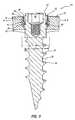
- FIG. 4is a cross-sectional view of the bone plate assembly of FIG. 1 with the screw in a first position
- FIG. 5is a cross-sectional view of the bone plate assembly of FIG. 1 with the screw in a second position;
- FIG. 6is a cross-sectional view of the bone plate assembly of FIG. 1 with the screw in a third position;
- FIG. 7is a close up view of a portion of the bone plate assembly of FIG. 6 ;
- FIG. 8is a side view of the bushing of the bone plate assembly of FIG. 1 ;
- FIG. 9is a top view of the bushing of the bone plate assembly of FIG. 1 ;
- FIG. 10is a cross-sectional view of the bushing of the bone plate assembly of FIG. 1 ;
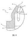
- FIG. 11is a close up view of a portion of the bushing shown in FIG. 9 ;
- FIG. 12is a side view of the screw of the bone plate assembly of FIG. 1 ;
- FIG. 13is a top view of the screw of the bone plate assembly of FIG. 1 ;
- FIG. 14is a cross-sectional view of the screw of the bone plate assembly of FIG. 1 ;
- FIG. 15is a close-up view of a head portion of the screw of FIG. 13 ;
- FIGS. 16A-Dare top views of several alternative plate embodiments for use with the bone plate assembly of FIG. 1 .
- the present disclosureis directed to a bone plate assembly that includes a bone plate, a bone screw, and a bushing member that provides backout protection for the screw relative to the plate.
- the example bushings disclosed hereinnot only provide backout protection for the screw, but may also provide a visual indicator to confirm when the screw has reached a locked position relative to the plate and bushing.
- FIG. 1illustrates a partially exploded view of the bone plate assembly 10 having a bone plate 12 , a plurality of bushings 16 , and a plurality of screws 14 .
- the bushings 16are mounted within through holes 24 of the plate 12 , followed by insertion of the screws 14 into the bushings 16 .
- the bone plate 12is shown having a construction that can span two intervertebral spaces (also known as a two level bone plate). However, bone plate 12 could be constructed to span more or fewer intervertebral spaces. Because plate 12 spans two intervertebral spaces, plate 12 is shown with two viewing windows 21 and through holes 24 corresponding to three vertebrae. More or fewer viewing windows 21 and through holes 24 may be provided in a single bone plate. For example, for a construction that spans only one intervertebral space, only one viewing window 21 and through holes 24 corresponding to 2 vertebrae may be used. Moreover, for a construction that spans three intervertebral spaces, three viewing windows 21 may be provided along with additional through holes 24 . Furthermore, the window 21 may be split into a plurality of smaller windows as a matter of design choice.
- a bone plate 12includes a top surface 20 and a bottom or bone facing surface 22 .
- the through holes 24extend from the top surface 20 to the bottom surface 22 .
- the through holes 24include an entrance portion 26 and an exit portion 28 .
- the through hole 24has a contoured surface 31 about entrance portion 26 .
- the contoured surface 31 about entrance portion 26includes a generally spherical or contoured surface 31 with a first curvature radius having a maximum diameter or dimension D 1 .
- the surface 31can also be described as a concave shaped surface 31 .
- the entrance portion 26is typically sized to receive and retain the bushing 16 .
- the bushing 16may need to be compressed or stressed to fit through entrance portion 26 . As shown in FIGS.
- through hole 24may have a channel 27 formed in a portion of the through hole 24 between the entrance portion 26 and the exit portion 28 .
- the channel 27also may include a generally spherical or contoured surface 31 with a second curvature radius having a maximum diameter or dimension D 0 generally greater than D 1 . As seen in cross section, this provides a step out like feature.
- Channel 27is generally sized to receive the bushing 16 in an unstressed state.
- the exit portion 28defines an exit diameter or dimension D 2 adjacent to the bottom surface 20 .
- the exit diameter D 2is sized smaller than a minimum width dimension of the head of the screw 14 such that only a shank portion of the screw 14 can pass through the through hole 24 and the head portion of the screw 14 is retained within the through hole 24 .
- the exit portionmay be described as a generally spherical or contoured surface having a third curvature radius. As seen in the cross section, the transition from channel 27 to exit portion 28 is a step in like feature.
- the plate 12has a length L 1 and a width W 1 as shown in FIGS. 2 and 3 .
- Many other length and width configurations for the plate 12are possible, such as plates shown in FIGS. 16A-D . While the various plates shown in FIGS. 16A-D have a relatively constant width W, the length varies for each plate. In other arrangements, not specifically shown, the length L can remain constant and the width W can vary. In yet other arrangements, both the width W and length L can vary among different bone plates.
- the through holes 24 shown in FIGS. 1-3have the same shape and size. In other arrangements, at least some of the through holes 24 have different sizes and shapes for a given plate 12 to accommodate different sized or shaped screws 14 or bushings 16 .
- the screw 14includes a shank 30 , a head 32 , a plurality of threads 34 , a top surface 36 , an instrument recess 38 , a locking protrusion 40 located on an intermediate portion between the shank 30 and head 32 , and a visual indicator protrusion 42 .
- the head 32has a plurality of spaced apart visual indicator protrusions 42 .
- the visual indicator protrusions 42have a maximum diameter or dimension D 4 as shown in FIG. 14
- the top surface of the headhas a smaller maximum diameter or dimension D 3 as shown in FIG. 12 .
- the intermediate portion about locking protrusion 40has a maximum diameter or dimension D 4 greater than D 3 and D 4 .
- the plurality of threads 34are positioned on the shank 30 .
- the instrument recess 38is defined in the top surface 36 and is sized to receive a portion of an installation instrument that can apply a twisting or torque force to the screw 14 .
- the locking protrusion 40 on the intermediate portion between the head 32 and the shank 30may include a plurality of locking protrusion members 40 as shown in at least FIGS. 13-15 .
- Each of the locking protrusions 40includes a locking surface 44 .
- the locking surface 44is arranged generally perpendicular to a longitudinal dimension of the screw 14 .
- the orientation of the locking surface 44may also be defined as facing a direction opposite the direction of insertion of the screw 14 into the plate 12 . Other shapes and sizes for the locking surface 44 are possible.
- the locking protrusions 40may define a maximum width dimension D 4 measured from an outer surface of one locking protrusion (i.e., furthest radial outward surface) to an outer surface of a locking protrusion positioned on an opposite side of the screw 14 .
- a visual indicator protrusion 42may include a plurality of spaced apart visual indicator protrusions 42 arranged around a periphery of the head 32 as shown in at least FIGS. 13 and 15 .
- Each of the visual indicator protrusions 42defines a visible surface or shelf 46 .
- the visual surface 46is shown arranged generally perpendicular to a longitudinal axis of the screw 14 .
- Visual surface 46also may be defined as facing a direction opposite the direction of insertion of the screw 14 into the plate 12 . Typically, the entire visual surface 46 is visible from the end view shown in FIG. 13 .
- the visual indicator protrusions 42define a maximum width dimension D 5 extending from an outer surface of one visual indicator protrusion 42 (i.e., furthest radial outward surface) to an outer surface of a visual indicator protrusion 42 in an opposite side of the head 32 (see FIG. 14 ). Covering or exposing portions of the visual surfaces 46 while implanting the bone plate assembly 10 in a patient may provide a visual indication to the operator concerning certain orientations of the screw 14 relative to the plate 12 and bushing 16 .
- the screw 14also may include at least one release instrument recess 48 around a periphery of the head 32 .
- the release instrument recess 48may provide space for a portion of an instrument or device to be inserted between the head 32 and the bushing 16 after the screw 14 has been locked into the bushing 16 (i.e., in the locked position shown in FIGS. 2 , 3 and 6 ).
- the inserted release instrument or device positioned within the release instrument recess 48may release or otherwise disengage the screw 14 from the bushing 16 to permit backing out of the screw 14 .
- the bushing 16includes a base portion 50 , a plurality of top tab members 52 , and a plurality of bottom tab members 54 .
- the base portion 50defines a ring structure from which the top and bottom tab members 52 , 54 extend in opposite directions.
- the base portion 50defines an outer contact surface 56 that defines a maximum outer diameter or dimension D 6 (see FIG. 10 ).
- the diameter D 6is substantially equal to the maximum internal diameter D 1 of the entrance portion 26 of the through hole 24 .
- the outer contact surface 56has a generally contoured shape to facilitate easier insertion of the bushing 16 into the entrance portion 26 through the opening of the through holes 24 along the top surface 20 .
- the bushing 16may be compressible such that the bushing 16 may be compressed to fit through the opening into entrance portion 26 .
- the bushing 16may include a gap (not shown). Once a compressive force that is used to compress the bushing 16 is removed (i.e., typically after the bushing 16 is positioned within the entrance portion 26 ), the bushing 16 expands such that the outer contact surface 56 cooperatively engages the spherical surface 30 within the entrance portion 26 .
- the bushing 16includes a generally shape that matches the contoured surface 30 of the channel 27 between the entrance portion 26 and exit portion 28 .
- the bushing 16has a shape that cooperatively engages the channel 27 and may allow polyaxial orientation of bushing 16 relative to plate 12 .
- the spherical shape of the channel 27may permit some movement of the base portion 50 within the channel 27 .
- the bushing 16may be able to tilt or rock back and forth within the channel 27 depending on an orientation of the screw 14 relative to the plate 12 .
- FIG. 1illustrates how the screws 14 may be inserted into the plate 12 at different relative angles.
- the entrance portion 26 and exit portion 28 of the through holes 24may be configured to permit various orientations of the screws 14 while still permitting operation of the bushing 16 to lock the screws 14 within the through holes 24 of the plate 12 .
- the top tab members 52are spaced apart around a periphery of the base portion 50 and extend in a vertically upward direction (i.e., a direction toward the top surface 20 of the plate 12 ).
- the top tab members 52define a top edge or surface 58 of the bushing 16 .
- a plurality of dividing slots 60may be used to define or space apart adjacent top tab members 52 .
- Each of the top tab members 52may include a screw contact surface 62 that is arranged facing generally radially inward towards the screw as the screw passes through the bushing 16 .
- the top tab members 52may also include an undercut surface 64 as shown in the detailed view of FIG. 11 .
- the top tab members 52define an internal diameter or dimension D 7 between the screw contact surface 62 of opposing top tab members 52 (see FIG. 10 ).
- the dimension D 7defines a minimum opening size into the bushing 56 when the top tab members 52 are in an unflexed or rest state.
- the screw contact surfaces 62engage a radially outward facing surface of the visual indicator protrusions 42 thereby flexing the top tab members 52 radially outward in the direction R.
- the dimension D 7is equal to or greater than the maximum dimension D 3 of the head 32 of the screw 14 .
- the top tab members 52typically maintain the rest or unflexed state until being engaged by the visual indicator protrusions 42 .
- the indicia of visual indicator protrusions 42may be, for example, a surface color, a surface texture, or the like.
- the top tab members 52move from the flexed state shown in FIG. 5 to the unflexed state shown in FIG. 6 , thereby inhibiting the viewing of at least a portion of the visual surface or shelf 46 . While it is preferable to provide the gap, undercut surface 64 and visual indicator protrusion 42 may abut. As the screw 14 passes through the bushing 16 , the entire visual surface 46 is usually visible to the operator until at least a portion of the visual indicator protrusion 42 moves past the undercut surface 64 .
- the top tab members 52are inhibiting the viewing of at least some portion or portions of the visual surface 46 as viewed from an end view of the screw 14 .
- This inhibiting of the viewing of portions of the visual surface 46 by the top tab members 52provides a visual indication to the operator that the screw has obtained a certain axial position relative to the bushing 16 .
- the axial position of the visual indicator protrusion 42 when positioned axially past the undercut surface 64is subsequent to or coincides with the locking engagement of the bottom tab members 54 with the locking protrusion 40 of the screw 14 .
- the bottom tab members 54are spaced apart around a periphery of the base portion 50 and extend in a downward direction (i.e., in a direction facing toward the bottom surface 22 of the plate 12 ).
- the bottom tab members 54define a bottom edge 70 of the bushing 16 .
- the bottom edge 70also defines a locking contact surface for engagement with the locking surface 44 of the locking protrusions 40 .
- a plurality of dividing slots 72extend from the bottom edge 70 toward the base portion 50 to space apart or divide adjacent tab members 54 .
- the locking protrusionpreferably resides between the head and the threaded portion of the shank.
- the bottom tab members 54also define a screw contact surface 74 that faces generally radially inward.
- the screw contact surface 74is arranged to contact a radially outward facing surface of the locking protrusions 40 as the screw 14 moves axially through the bushing 16 .
- the bottom tab members 54define a maximum inner diameter or dimension D 9 measured between the screw contact surface 74 of opposing tab members as shown in at least FIG. 10 .
- An example backout protection bushing, having a plurality of bottom tab members,is described in U.S. Pat. No. 7,175,623, which is incorporated herein by reference in its entirety.
- the bushing 16is first inserted into the through hole 24 of the plate 12 as shown in FIG. 4 .
- the bushing 16is typically inserted during manufacturing or at least pre-surgery.
- the screw 14is inserted into the bushing 16 until the locking protrusion 40 begins to engage the screw contact surface 74 of bottom tab members 54 , and the visual indicator protrusion 42 begins to engage the screw contact surface 62 of the top tab members 52 (see FIG. 5 ).
- the screw 14attains a locked position when the locking protrusions 40 have moved axially past the bottom edge 70 of the bottom tab members 54 so that the bottom edge 70 contacts the locking surface 44 of locking protrusions 40 .
- the visual indicator protrusions 42move past the undercut surface 64 of the top tab members 52 so that the undercut surface 64 faces and resides above the visual surface 46 (see FIGS. 6-7 ).
- no portion of the top tab members 52engages the screw 14 when the screw is in the locked position.
- the bushing 16 when lockedis in an unstressed condition and no part of the screw flexes or stresses the bushing 16 .
- the screw 14is prevented from backing out or unscrewing relative to the plate 12 by the placement of the bottom edge 70 of the bottom tab members 54 above the locking surface 44 of the locking protrusion 40 on the screw 14 .
- the locking surface 44will not be able to move past bottom edge 70 in the normal course inhibiting the amount of backing out, although some reverse threading may be possible as bottom edge 70 may be positioned a distance from locking surface 44 .
- reverse screwing (i.e., backing out) of the screw 14may be accomplished if the bottom tab members 54 are flexed outward in the direction R to at least a dimension D 4 .
- Such flexing of the bottom tab members 54may be accomplished by inserting a release tool into at least one of the released instrument recesses 48 defined on the head 32 of the screw 14 .
Landscapes
- Health & Medical Sciences (AREA)
- Orthopedic Medicine & Surgery (AREA)
- Surgery (AREA)
- Life Sciences & Earth Sciences (AREA)
- Heart & Thoracic Surgery (AREA)
- Nuclear Medicine, Radiotherapy & Molecular Imaging (AREA)
- Engineering & Computer Science (AREA)
- Biomedical Technology (AREA)
- Neurology (AREA)
- Medical Informatics (AREA)
- Molecular Biology (AREA)
- Animal Behavior & Ethology (AREA)
- General Health & Medical Sciences (AREA)
- Public Health (AREA)
- Veterinary Medicine (AREA)
- Surgical Instruments (AREA)
Abstract
Description
Claims (19)
Priority Applications (1)
| Application Number | Priority Date | Filing Date | Title |
|---|---|---|---|
| US12/419,012US8211154B2 (en) | 2009-04-06 | 2009-04-06 | Bone plate assemblies with backout protection and visual indicator |
Applications Claiming Priority (1)
| Application Number | Priority Date | Filing Date | Title |
|---|---|---|---|
| US12/419,012US8211154B2 (en) | 2009-04-06 | 2009-04-06 | Bone plate assemblies with backout protection and visual indicator |
Publications (2)
| Publication Number | Publication Date |
|---|---|
| US20100256686A1 US20100256686A1 (en) | 2010-10-07 |
| US8211154B2true US8211154B2 (en) | 2012-07-03 |
Family
ID=42826837
Family Applications (1)
| Application Number | Title | Priority Date | Filing Date |
|---|---|---|---|
| US12/419,012Expired - Fee RelatedUS8211154B2 (en) | 2009-04-06 | 2009-04-06 | Bone plate assemblies with backout protection and visual indicator |
Country Status (1)
| Country | Link |
|---|---|
| US (1) | US8211154B2 (en) |
Cited By (17)
| Publication number | Priority date | Publication date | Assignee | Title |
|---|---|---|---|---|
| US20130053887A1 (en)* | 2011-08-26 | 2013-02-28 | Life Spine, Inc. | Bone Screw Retention in a Spinal Implant |
| US8814912B2 (en) | 2012-07-27 | 2014-08-26 | Zimmer Spine, Inc. | Bone stabilization member with bone screw retention mechanism |
| US20140324109A1 (en)* | 2011-05-27 | 2014-10-30 | Globus Medical, Inc | Securing Fasteners |
| US20160151166A1 (en)* | 2014-07-01 | 2016-06-02 | Alliance Partners, Llc | Low profile standalone cervical interbody with screw locking clips and method of using same |
| US9451992B2 (en)* | 2010-12-01 | 2016-09-27 | Facet-Link Inc. | Variable angle bone screw fixation arrangement |
| US9504584B1 (en) | 2011-01-28 | 2016-11-29 | Nuvasive, Inc. | Spinal fusion implant and related methods |
| USD775731S1 (en) | 2015-03-24 | 2017-01-03 | Asfora Ip, Llc | Bone plate |
| USD775732S1 (en) | 2015-03-24 | 2017-01-03 | Asfora Ip, Llc | Bone plate |
| USD807508S1 (en) | 2015-03-24 | 2018-01-09 | Asfora Ip, Llc | Bone plate |
| US20180042652A1 (en)* | 2011-07-15 | 2018-02-15 | Globus Medical, Inc. | Screw implants for bone fusion |
| US10010423B2 (en) | 2013-03-15 | 2018-07-03 | Avinash Kumar | Anatomical humeral fixation system and method |
| US20180360512A1 (en)* | 2011-07-15 | 2018-12-20 | Globus Medical, Inc. | Screw implants for bone fusion |
| US10617451B2 (en) | 2015-12-01 | 2020-04-14 | Revivo Medical, Llc | Bone fixation apparatus with fastener securement mechanism and methods of use |
| US11039865B2 (en) | 2018-03-02 | 2021-06-22 | Stryker European Operations Limited | Bone plates and associated screws |
| US20210196329A1 (en)* | 2016-03-17 | 2021-07-01 | Stryker European Operations Holdings Llc | Floating Locking Insert |
| US11123117B1 (en) | 2011-11-01 | 2021-09-21 | Nuvasive, Inc. | Surgical fixation system and related methods |
| US20230293003A1 (en)* | 2022-03-21 | 2023-09-21 | Yih-Chiou Tsai | Vaginal speculum |
Families Citing this family (31)
| Publication number | Priority date | Publication date | Assignee | Title |
|---|---|---|---|---|
| US8444681B2 (en) | 2009-06-15 | 2013-05-21 | Roger P. Jackson | Polyaxial bone anchor with pop-on shank, friction fit retainer and winged insert |
| US9980753B2 (en) | 2009-06-15 | 2018-05-29 | Roger P Jackson | pivotal anchor with snap-in-place insert having rotation blocking extensions |
| US20070198016A1 (en)* | 2006-02-21 | 2007-08-23 | Osteomed, L.P. | Compression stabilizing spacers |
| US8979904B2 (en) | 2007-05-01 | 2015-03-17 | Roger P Jackson | Connecting member with tensioned cord, low profile rigid sleeve and spacer with torsion control |
| US8388666B2 (en)* | 2007-09-27 | 2013-03-05 | Biomet C.V. | Locking screw system with relatively hard spiked polyaxial bushing |
| AU2010260521C1 (en) | 2008-08-01 | 2013-08-01 | Roger P. Jackson | Longitudinal connecting member with sleeved tensioned cords |
| US9358050B2 (en) | 2011-10-14 | 2016-06-07 | Globus Medical, Inc. | Orthopedic anchor assembly |
| US20100217399A1 (en)* | 2009-02-22 | 2010-08-26 | Groh Gordon I | Base plate system for shoulder arthroplasty and method of using the same |
| CN103826560A (en) | 2009-06-15 | 2014-05-28 | 罗杰.P.杰克逊 | Polyaxial Bone Anchor with Socket Stem and Winged Inserts with Friction Fit Compression Collars |
| US11464549B2 (en) | 2009-06-15 | 2022-10-11 | Roger P. Jackson | Pivotal bone anchor assembly with horizontal tool engagement grooves and insert with upright arms having flared outer portions |
| EP2485654B1 (en) | 2009-10-05 | 2021-05-05 | Jackson P. Roger | Polyaxial bone anchor with non-pivotable retainer and pop-on shank, some with friction fit |
| AU2011324058A1 (en) | 2010-11-02 | 2013-06-20 | Roger P. Jackson | Polyaxial bone anchor with pop-on shank and pivotable retainer |
| CN102068302B (en)* | 2010-12-20 | 2012-09-05 | 常州市康辉医疗器械有限公司 | Bone screw anti-back device for internal spinal fixation system |
| US9084636B2 (en)* | 2011-01-10 | 2015-07-21 | Spine Craft, LLC | Surgical plate system and method |
| JP5865479B2 (en) | 2011-03-24 | 2016-02-17 | ロジャー・ピー・ジャクソン | Multiaxial bone anchor with compound joint and pop-mounted shank |
| AU2012271441B2 (en) | 2011-06-15 | 2017-02-02 | Smith & Nephew, Inc. | Variable angle locking implant |
| US8591556B2 (en) | 2011-07-19 | 2013-11-26 | Globus Medical, Inc. | Locking confirmation mechanism for a bone screw and plate assembly |
| EP2623058A3 (en)* | 2012-02-06 | 2013-09-11 | Crcaholic S.A. | Fixing device and tool for surgical holding systems |
| GB201207975D0 (en)* | 2012-05-08 | 2012-06-20 | Ortho Solutions Ltd | Improvements in or relating to pelvic reconstruction |
| US20150238233A1 (en)* | 2012-08-09 | 2015-08-27 | Trinity Orthopedics, Llc | Intervertebral Plate Systems and Methods of Use |
| EP2911616B1 (en)* | 2012-10-29 | 2020-10-07 | NuVasive Specialized Orthopedics, Inc. | Adjustable devices for treating arthritis of the knee |
| US9510880B2 (en) | 2013-08-13 | 2016-12-06 | Zimmer, Inc. | Polyaxial locking mechanism |
| US20160058564A1 (en)* | 2014-09-03 | 2016-03-03 | Globus Medical Inc. | Intervertebral Implants and Related Methods of Use |
| US10258395B2 (en) | 2014-09-25 | 2019-04-16 | Stryker European Holdings I, Llc | Bone plate locking mechanism |
| US10543021B2 (en) | 2014-10-21 | 2020-01-28 | Roger P. Jackson | Pivotal bone anchor assembly having an open ring positioner for a retainer |
| US9924975B2 (en) | 2014-10-21 | 2018-03-27 | Roger P. Jackson | Bone anchor having a snap-fit assembly |
| GB2557840B (en) | 2015-09-18 | 2021-07-21 | Smith & Nephew Inc | Bone plate |
| CN115702972B (en)* | 2021-08-16 | 2025-09-12 | 蔡益秋 | vaginal dilators |
| US20230293002A1 (en)* | 2022-03-21 | 2023-09-21 | Yih-Chiou Tsai | Vaginal speculum |
| WO2023199903A1 (en)* | 2022-04-12 | 2023-10-19 | ニプロ株式会社 | Fixation plate screw tilt angle adjustment ring and fixation plate fixing system using same |
| USD1037845S1 (en)* | 2022-11-08 | 2024-08-06 | Madhu Sudan Saini | Screw |
Citations (48)
| Publication number | Priority date | Publication date | Assignee | Title |
|---|---|---|---|---|
| US2409638A (en) | 1944-08-07 | 1946-10-22 | Oliver Iron And Steel Corp | Insert bolt |
| US3486505A (en) | 1967-05-22 | 1969-12-30 | Gordon M Morrison | Orthopedic surgical instrument |
| US3711347A (en) | 1968-12-09 | 1973-01-16 | D Wagner | Method of sealing and locking a fastener |
| US3750652A (en) | 1971-03-05 | 1973-08-07 | J Sherwin | Knee retractor |
| US3834021A (en) | 1973-01-24 | 1974-09-10 | Long W De | Precision instrument system |
| US4794918A (en) | 1985-05-06 | 1989-01-03 | Dietmar Wolter | Bone plate arrangement |
| US5085660A (en) | 1990-11-19 | 1992-02-04 | Lin Kwan C | Innovative locking plate system |
| US5364399A (en) | 1993-02-05 | 1994-11-15 | Danek Medical, Inc. | Anterior cervical plating system |
| US5407312A (en) | 1993-10-04 | 1995-04-18 | Terrizzi; A. Scott | Fastener system with an entrainable function-facilitating material |
| US5558674A (en) | 1993-12-17 | 1996-09-24 | Smith & Nephew Richards, Inc. | Devices and methods for posterior spinal fixation |
| US5578034A (en) | 1995-06-07 | 1996-11-26 | Danek Medical, Inc. | Apparatus for preventing screw backout in a bone plate fixation system |
| US5676666A (en) | 1994-08-23 | 1997-10-14 | Spinetech, Inc. | Cervical spine stabilization system |
| US5741258A (en) | 1993-01-25 | 1998-04-21 | Synthes (U.S.A.) | Lock washer for bone plate osteosynthesis |
| US5782830A (en) | 1995-10-16 | 1998-07-21 | Sdgi Holdings, Inc. | Implant insertion device |
| US5885299A (en) | 1994-09-15 | 1999-03-23 | Surgical Dynamics, Inc. | Apparatus and method for implant insertion |
| US5904683A (en) | 1998-07-10 | 1999-05-18 | Sulzer Spine-Tech Inc. | Anterior cervical vertebral stabilizing device |
| US5951558A (en) | 1998-04-22 | 1999-09-14 | Fiz; Daniel | Bone fixation device |
| US5954722A (en) | 1997-07-29 | 1999-09-21 | Depuy Acromed, Inc. | Polyaxial locking plate |
| US5957927A (en) | 1998-02-24 | 1999-09-28 | Synthes (Usa) | Bone fixation device introducer |
| WO1999056653A1 (en) | 1998-04-30 | 1999-11-11 | Societe De Fabrication De Materiel Orthopedique (Sofamor) | Bone plate with bone screw securing means |
| US6129730A (en) | 1999-02-10 | 2000-10-10 | Depuy Acromed, Inc. | Bi-fed offset pitch bone screw |
| US6139550A (en) | 1997-02-11 | 2000-10-31 | Michelson; Gary K. | Skeletal plating system |
| US6152927A (en) | 1997-05-15 | 2000-11-28 | Sdgi Holdings, Inc. | Anterior cervical plating system |
| US6159213A (en) | 1998-10-02 | 2000-12-12 | Rogozinski; Chaim | Cervical plate |
| US6193721B1 (en) | 1997-02-11 | 2001-02-27 | Gary K. Michelson | Multi-lock anterior cervical plating system |
| US6224599B1 (en) | 1999-05-19 | 2001-05-01 | Matthew G. Baynham | Viewable wedge distractor device |
| US6224602B1 (en) | 1999-10-11 | 2001-05-01 | Interpore Cross International | Bone stabilization plate with a secured-locking mechanism for cervical fixation |
| US20010001119A1 (en) | 1999-09-27 | 2001-05-10 | Alan Lombardo | Surgical screw system and related methods |
| US6235033B1 (en) | 2000-04-19 | 2001-05-22 | Synthes (Usa) | Bone fixation assembly |
| US6235034B1 (en) | 1997-10-24 | 2001-05-22 | Robert S. Bray | Bone plate and bone screw guide mechanism |
| US6258089B1 (en) | 1998-05-19 | 2001-07-10 | Alphatec Manufacturing, Inc. | Anterior cervical plate and fixation system |
| US6261291B1 (en) | 1999-07-08 | 2001-07-17 | David J. Talaber | Orthopedic implant assembly |
| US6261296B1 (en) | 1998-10-02 | 2001-07-17 | Synthes U.S.A. | Spinal disc space distractor |
| US6306139B1 (en) | 1998-10-19 | 2001-10-23 | Scint'x | Intervertebral connection device with an anti-extraction device to prevent extraction of anchoring screws |
| US20020015189A1 (en) | 2000-02-15 | 2002-02-07 | Ricoh Company, Ltd. | Digital image reading apparatus |
| US6413259B1 (en) | 2000-12-14 | 2002-07-02 | Blackstone Medical, Inc | Bone plate assembly including a screw retaining member |
| US6436101B1 (en) | 1999-10-13 | 2002-08-20 | James S. Hamada | Rasp for use in spine surgery |
| US20020120273A1 (en) | 1999-10-13 | 2002-08-29 | Needham Dusty Anna | Anterior cervical plating system and method |
| US6503250B2 (en) | 2000-11-28 | 2003-01-07 | Kamaljit S. Paul | Bone support assembly |
| US20030040749A1 (en) | 2001-08-24 | 2003-02-27 | Grabowski John J. | Bone fixation device |
| US20030060828A1 (en) | 2001-06-06 | 2003-03-27 | Michelson Gary K. | Dynamic multilock anterior cervical plate system having non-detachably fastened and moveable segments, instrumentation, and method for installation thereof |
| US20030078583A1 (en) | 2001-10-23 | 2003-04-24 | Biedermann Motech Gmbh | Bone fixing device |
| US6565303B1 (en) | 2001-07-16 | 2003-05-20 | Olympic Manufacturing Group, Inc. | Washer and assembly of same employing a securing member |
| US6602255B1 (en)* | 2000-06-26 | 2003-08-05 | Stryker Spine | Bone screw retaining system |
| US6695846B2 (en) | 2002-03-12 | 2004-02-24 | Spinal Innovations, Llc | Bone plate and screw retaining mechanism |
| US7172593B2 (en) | 2000-10-25 | 2007-02-06 | Sdgi Holdings, Inc. | Non-metallic implant devices and intra-operative methods for assembly and fixation |
| US7175623B2 (en)* | 2002-06-24 | 2007-02-13 | Lanx, Llc | Cervical plate with backout protection |
| US7229443B2 (en) | 1998-07-20 | 2007-06-12 | Biedermann Motech Gmbh | Fastening assembly with improved handling properties |
- 2009
- 2009-04-06USUS12/419,012patent/US8211154B2/ennot_activeExpired - Fee Related
Patent Citations (51)
| Publication number | Priority date | Publication date | Assignee | Title |
|---|---|---|---|---|
| US2409638A (en) | 1944-08-07 | 1946-10-22 | Oliver Iron And Steel Corp | Insert bolt |
| US3486505A (en) | 1967-05-22 | 1969-12-30 | Gordon M Morrison | Orthopedic surgical instrument |
| US3711347A (en) | 1968-12-09 | 1973-01-16 | D Wagner | Method of sealing and locking a fastener |
| US3750652A (en) | 1971-03-05 | 1973-08-07 | J Sherwin | Knee retractor |
| US3834021A (en) | 1973-01-24 | 1974-09-10 | Long W De | Precision instrument system |
| US4794918A (en) | 1985-05-06 | 1989-01-03 | Dietmar Wolter | Bone plate arrangement |
| US5085660A (en) | 1990-11-19 | 1992-02-04 | Lin Kwan C | Innovative locking plate system |
| US5741258A (en) | 1993-01-25 | 1998-04-21 | Synthes (U.S.A.) | Lock washer for bone plate osteosynthesis |
| US5364399A (en) | 1993-02-05 | 1994-11-15 | Danek Medical, Inc. | Anterior cervical plating system |
| US5407312A (en) | 1993-10-04 | 1995-04-18 | Terrizzi; A. Scott | Fastener system with an entrainable function-facilitating material |
| US5558674A (en) | 1993-12-17 | 1996-09-24 | Smith & Nephew Richards, Inc. | Devices and methods for posterior spinal fixation |
| US5676666A (en) | 1994-08-23 | 1997-10-14 | Spinetech, Inc. | Cervical spine stabilization system |
| US5885299A (en) | 1994-09-15 | 1999-03-23 | Surgical Dynamics, Inc. | Apparatus and method for implant insertion |
| US5578034A (en) | 1995-06-07 | 1996-11-26 | Danek Medical, Inc. | Apparatus for preventing screw backout in a bone plate fixation system |
| US5782830A (en) | 1995-10-16 | 1998-07-21 | Sdgi Holdings, Inc. | Implant insertion device |
| US6139550A (en) | 1997-02-11 | 2000-10-31 | Michelson; Gary K. | Skeletal plating system |
| US6193721B1 (en) | 1997-02-11 | 2001-02-27 | Gary K. Michelson | Multi-lock anterior cervical plating system |
| US6152927A (en) | 1997-05-15 | 2000-11-28 | Sdgi Holdings, Inc. | Anterior cervical plating system |
| US5954722A (en) | 1997-07-29 | 1999-09-21 | Depuy Acromed, Inc. | Polyaxial locking plate |
| US6235034B1 (en) | 1997-10-24 | 2001-05-22 | Robert S. Bray | Bone plate and bone screw guide mechanism |
| US5957927A (en) | 1998-02-24 | 1999-09-28 | Synthes (Usa) | Bone fixation device introducer |
| US5951558A (en) | 1998-04-22 | 1999-09-14 | Fiz; Daniel | Bone fixation device |
| WO1999056653A1 (en) | 1998-04-30 | 1999-11-11 | Societe De Fabrication De Materiel Orthopedique (Sofamor) | Bone plate with bone screw securing means |
| US6626907B2 (en) | 1998-05-19 | 2003-09-30 | Alphatec Manufacturing, Inc. | Anterior cervical plate and fixation system |
| US20010041894A1 (en) | 1998-05-19 | 2001-11-15 | Campbell Christopher M. | Anterior cervical plate and fixation system |
| US6258089B1 (en) | 1998-05-19 | 2001-07-10 | Alphatec Manufacturing, Inc. | Anterior cervical plate and fixation system |
| US5904683A (en) | 1998-07-10 | 1999-05-18 | Sulzer Spine-Tech Inc. | Anterior cervical vertebral stabilizing device |
| US7229443B2 (en) | 1998-07-20 | 2007-06-12 | Biedermann Motech Gmbh | Fastening assembly with improved handling properties |
| US6159213A (en) | 1998-10-02 | 2000-12-12 | Rogozinski; Chaim | Cervical plate |
| US6261296B1 (en) | 1998-10-02 | 2001-07-17 | Synthes U.S.A. | Spinal disc space distractor |
| US6306139B1 (en) | 1998-10-19 | 2001-10-23 | Scint'x | Intervertebral connection device with an anti-extraction device to prevent extraction of anchoring screws |
| US6129730A (en) | 1999-02-10 | 2000-10-10 | Depuy Acromed, Inc. | Bi-fed offset pitch bone screw |
| US6224599B1 (en) | 1999-05-19 | 2001-05-01 | Matthew G. Baynham | Viewable wedge distractor device |
| US6261291B1 (en) | 1999-07-08 | 2001-07-17 | David J. Talaber | Orthopedic implant assembly |
| US20010001119A1 (en) | 1999-09-27 | 2001-05-10 | Alan Lombardo | Surgical screw system and related methods |
| US6224602B1 (en) | 1999-10-11 | 2001-05-01 | Interpore Cross International | Bone stabilization plate with a secured-locking mechanism for cervical fixation |
| US20020120273A1 (en) | 1999-10-13 | 2002-08-29 | Needham Dusty Anna | Anterior cervical plating system and method |
| US6436101B1 (en) | 1999-10-13 | 2002-08-20 | James S. Hamada | Rasp for use in spine surgery |
| US6533786B1 (en) | 1999-10-13 | 2003-03-18 | Sdgi Holdings, Inc. | Anterior cervical plating system |
| US20020015189A1 (en) | 2000-02-15 | 2002-02-07 | Ricoh Company, Ltd. | Digital image reading apparatus |
| US6235033B1 (en) | 2000-04-19 | 2001-05-22 | Synthes (Usa) | Bone fixation assembly |
| US6602255B1 (en)* | 2000-06-26 | 2003-08-05 | Stryker Spine | Bone screw retaining system |
| US7172593B2 (en) | 2000-10-25 | 2007-02-06 | Sdgi Holdings, Inc. | Non-metallic implant devices and intra-operative methods for assembly and fixation |
| US6503250B2 (en) | 2000-11-28 | 2003-01-07 | Kamaljit S. Paul | Bone support assembly |
| US6413259B1 (en) | 2000-12-14 | 2002-07-02 | Blackstone Medical, Inc | Bone plate assembly including a screw retaining member |
| US20030060828A1 (en) | 2001-06-06 | 2003-03-27 | Michelson Gary K. | Dynamic multilock anterior cervical plate system having non-detachably fastened and moveable segments, instrumentation, and method for installation thereof |
| US6565303B1 (en) | 2001-07-16 | 2003-05-20 | Olympic Manufacturing Group, Inc. | Washer and assembly of same employing a securing member |
| US20030040749A1 (en) | 2001-08-24 | 2003-02-27 | Grabowski John J. | Bone fixation device |
| US20030078583A1 (en) | 2001-10-23 | 2003-04-24 | Biedermann Motech Gmbh | Bone fixing device |
| US6695846B2 (en) | 2002-03-12 | 2004-02-24 | Spinal Innovations, Llc | Bone plate and screw retaining mechanism |
| US7175623B2 (en)* | 2002-06-24 | 2007-02-13 | Lanx, Llc | Cervical plate with backout protection |
Cited By (34)
| Publication number | Priority date | Publication date | Assignee | Title |
|---|---|---|---|---|
| US9451992B2 (en)* | 2010-12-01 | 2016-09-27 | Facet-Link Inc. | Variable angle bone screw fixation arrangement |
| US9913730B1 (en) | 2011-01-28 | 2018-03-13 | Nuvasive, Inc. | Spinal fixation system and related methods |
| US9504584B1 (en) | 2011-01-28 | 2016-11-29 | Nuvasive, Inc. | Spinal fusion implant and related methods |
| US20140324109A1 (en)* | 2011-05-27 | 2014-10-30 | Globus Medical, Inc | Securing Fasteners |
| US20170196605A1 (en)* | 2011-05-27 | 2017-07-13 | Globus Medical, Inc. | Securing fasteners |
| US10231763B2 (en)* | 2011-05-27 | 2019-03-19 | Globus Medical, Inc. | Securing fasteners |
| US9271774B2 (en)* | 2011-05-27 | 2016-03-01 | Globus Medical, Inc. | Securing fasteners |
| US11986224B2 (en) | 2011-05-27 | 2024-05-21 | Globus Medical, Inc. | Securing fasteners |
| US9636156B2 (en)* | 2011-05-27 | 2017-05-02 | Globus Medical, Inc. | Securing fasteners |
| US20160100868A1 (en)* | 2011-05-27 | 2016-04-14 | Globus Medical, Inc. | Securing fasteners |
| US11172967B2 (en) | 2011-05-27 | 2021-11-16 | Globus Medical Inc. | Securing fasteners |
| US10335216B2 (en)* | 2011-07-15 | 2019-07-02 | Globus Medical, Inc. | Screw implants for bone fusion |
| US20180360512A1 (en)* | 2011-07-15 | 2018-12-20 | Globus Medical, Inc. | Screw implants for bone fusion |
| US10925653B2 (en)* | 2011-07-15 | 2021-02-23 | Globus Medical, Inc. | Screw implants for bone fusion |
| US20180042652A1 (en)* | 2011-07-15 | 2018-02-15 | Globus Medical, Inc. | Screw implants for bone fusion |
| US20130053887A1 (en)* | 2011-08-26 | 2013-02-28 | Life Spine, Inc. | Bone Screw Retention in a Spinal Implant |
| US9351768B2 (en)* | 2011-08-26 | 2016-05-31 | Life Spine, Inc. | Bone screw retention in a spinal implant |
| US11123117B1 (en) | 2011-11-01 | 2021-09-21 | Nuvasive, Inc. | Surgical fixation system and related methods |
| US8814912B2 (en) | 2012-07-27 | 2014-08-26 | Zimmer Spine, Inc. | Bone stabilization member with bone screw retention mechanism |
| US9937056B2 (en) | 2012-07-27 | 2018-04-10 | Zimmer Spine, Inc. | Bone stabilization member with bone screw retention mechanism |
| US9414937B2 (en) | 2012-07-27 | 2016-08-16 | Zimmer Spine, Inc. | Bone stabilization member with bone screw retention mechanism |
| US10010423B2 (en) | 2013-03-15 | 2018-07-03 | Avinash Kumar | Anatomical humeral fixation system and method |
| US20160151166A1 (en)* | 2014-07-01 | 2016-06-02 | Alliance Partners, Llc | Low profile standalone cervical interbody with screw locking clips and method of using same |
| USD775731S1 (en) | 2015-03-24 | 2017-01-03 | Asfora Ip, Llc | Bone plate |
| USD814635S1 (en) | 2015-03-24 | 2018-04-03 | Asfora Ip, Llc | Bone plate |
| USD807508S1 (en) | 2015-03-24 | 2018-01-09 | Asfora Ip, Llc | Bone plate |
| USD775732S1 (en) | 2015-03-24 | 2017-01-03 | Asfora Ip, Llc | Bone plate |
| US10617451B2 (en) | 2015-12-01 | 2020-04-14 | Revivo Medical, Llc | Bone fixation apparatus with fastener securement mechanism and methods of use |
| US20210196329A1 (en)* | 2016-03-17 | 2021-07-01 | Stryker European Operations Holdings Llc | Floating Locking Insert |
| US12193716B2 (en)* | 2016-03-17 | 2025-01-14 | Stryker European Operations Holdings Llc | Floating locking insert |
| US11039865B2 (en) | 2018-03-02 | 2021-06-22 | Stryker European Operations Limited | Bone plates and associated screws |
| US12144529B2 (en) | 2018-03-02 | 2024-11-19 | Stryker European Operations Limited | Bone plates and associated screws |
| US20230293003A1 (en)* | 2022-03-21 | 2023-09-21 | Yih-Chiou Tsai | Vaginal speculum |
| US12310565B2 (en)* | 2022-03-21 | 2025-05-27 | Yih-Chiou Tsai | Vaginal speculum |
Also Published As
| Publication number | Publication date |
|---|---|
| US20100256686A1 (en) | 2010-10-07 |
Similar Documents
| Publication | Publication Date | Title |
|---|---|---|
| US8211154B2 (en) | Bone plate assemblies with backout protection and visual indicator | |
| US20220054277A1 (en) | Intervertebral implant | |
| CA2749430C (en) | Flexible spinal stabilization assembly with spacers having off-axis core member | |
| EP1994902B1 (en) | Pedicle screw fixation system | |
| US8486115B2 (en) | Spinal plate assemblies with backout protection cap and methods | |
| EP2451369B1 (en) | Vertebral stabilization transition connector | |
| US8439923B2 (en) | Poly-axial pedicle screw assembly | |
| US7309340B2 (en) | Method and apparatus for bone plating | |
| US10206722B2 (en) | Bone plate system | |
| US9101422B2 (en) | Spinal plate system for stabilizing a portion of a spine | |
| EP2769692B1 (en) | Iliosacral polyaxial screw | |
| JP6486277B2 (en) | Orthopedic fixation device | |
| EP2747686B1 (en) | Laminoplasty plates, systems, and devices | |
| US9763715B2 (en) | Surgical plate system and method | |
| EP3409225B1 (en) | Vertebral stabilization system | |
| US7481811B2 (en) | Translational plate with spring beam retainer | |
| EP1946711A1 (en) | Improved polyaxial screwdriver for a pedicle screw system | |
| US9039744B2 (en) | Spinal plate assembly | |
| EP3434211A1 (en) | Spinal stabilization device | |
| KR100704150B1 (en) | Spinal fixation screw | |
| WO2010047688A1 (en) | Screw with locking mechanism and rigid/dynamic bone plate | |
| US11857224B2 (en) | Bone plate | |
| KR102122716B1 (en) | lumbar plate | |
| WO2009114014A1 (en) | Locking cervical screw and methods of use thereof | |
| HK1005220B (en) | Bone fixation device, particularly of the sacrum, for spinal osteosynthesis |
Legal Events
| Date | Code | Title | Description |
|---|---|---|---|
| AS | Assignment | Owner name:LANX, INC., COLORADO Free format text:ASSIGNMENT OF ASSIGNORS INTEREST;ASSIGNORS:FISHER, JAMES;BURKHOLDER, ALAN;FULTON, MICHAEL;SIGNING DATES FROM 20090601 TO 20090626;REEL/FRAME:022883/0147 | |
| ZAAA | Notice of allowance and fees due | Free format text:ORIGINAL CODE: NOA | |
| ZAAB | Notice of allowance mailed | Free format text:ORIGINAL CODE: MN/=. | |
| STCF | Information on status: patent grant | Free format text:PATENTED CASE | |
| FEPP | Fee payment procedure | Free format text:PAT HOLDER NO LONGER CLAIMS SMALL ENTITY STATUS, ENTITY STATUS SET TO UNDISCOUNTED (ORIGINAL EVENT CODE: STOL); ENTITY STATUS OF PATENT OWNER: LARGE ENTITY | |
| AS | Assignment | Owner name:BANK OF AMERICA, N.A., AS ADMINISTRATIVE AGENT, NORTH CAROLINA Free format text:SECURITY AGREEMENT;ASSIGNOR:LANX, INC.;REEL/FRAME:032086/0664 Effective date:20140113 Owner name:BANK OF AMERICA, N.A., AS ADMINISTRATIVE AGENT, NO Free format text:SECURITY AGREEMENT;ASSIGNOR:LANX, INC.;REEL/FRAME:032086/0664 Effective date:20140113 | |
| AS | Assignment | Owner name:LANX, INC., COLORADO Free format text:RELEASE OF SECURITY INTEREST IN PATENTS RECORDED AT REEL 032086/ FRAME 0664;ASSIGNOR:BANK OF AMERICA, N.A., AS ADMINISTRATIVE AGENT;REEL/FRAME:037155/0041 Effective date:20150624 | |
| FPAY | Fee payment | Year of fee payment:4 | |
| AS | Assignment | Owner name:ZIMMER BIOMET SPINE, INC., COLORADO Free format text:CHANGE OF NAME;ASSIGNOR:LANX, INC.;REEL/FRAME:037761/0231 Effective date:20150730 | |
| AS | Assignment | Owner name:ZIMMER BIOMET SPINE, INC., COLORADO Free format text:CORRECTIVE ASSIGNMENT TO CORRECT THE REMOVE APPL. NO. 14/828,714 PREVIOUSLY RECORDED AT REEL: 037761 FRAME: 0231. ASSIGNOR(S) HEREBY CONFIRMS THE CHANGE OF NAME;ASSIGNOR:LANX, INC.;REEL/FRAME:038951/0064 Effective date:20150730 | |
| MAFP | Maintenance fee payment | Free format text:PAYMENT OF MAINTENANCE FEE, 8TH YEAR, LARGE ENTITY (ORIGINAL EVENT CODE: M1552); ENTITY STATUS OF PATENT OWNER: LARGE ENTITY Year of fee payment:8 | |
| AS | Assignment | Owner name:JPMORGAN CHASE BANK, N.A., AS ADMINISTRATIVE AGENT, NEW YORK Free format text:SECURITY INTEREST;ASSIGNORS:BIOMET 3I, LLC;EBI, LLC;ZIMMER BIOMET SPINE, INC.;AND OTHERS;REEL/FRAME:059293/0213 Effective date:20220228 | |
| FEPP | Fee payment procedure | Free format text:MAINTENANCE FEE REMINDER MAILED (ORIGINAL EVENT CODE: REM.); ENTITY STATUS OF PATENT OWNER: LARGE ENTITY | |
| AS | Assignment | Owner name:CERBERUS BUSINESS FINANCE AGENCY, LLC, NEW YORK Free format text:GRANT OF A SECURITY INTEREST -- PATENTS;ASSIGNORS:ZIMMER BIOMET SPINE, LLC;EBI, LLC;REEL/FRAME:066970/0806 Effective date:20240401 | |
| AS | Assignment | Owner name:ZIMMER BIOMET SPINE, LLC (F/K/A ZIMMER BIOMET SPINE, INC.), COLORADO Free format text:RELEASE BY SECURED PARTY;ASSIGNOR:JPMORGAN CHASE BANK, N.A.;REEL/FRAME:066973/0833 Effective date:20240401 Owner name:EBI, LLC, NEW JERSEY Free format text:RELEASE BY SECURED PARTY;ASSIGNOR:JPMORGAN CHASE BANK, N.A.;REEL/FRAME:066973/0833 Effective date:20240401 | |
| LAPS | Lapse for failure to pay maintenance fees | Free format text:PATENT EXPIRED FOR FAILURE TO PAY MAINTENANCE FEES (ORIGINAL EVENT CODE: EXP.); ENTITY STATUS OF PATENT OWNER: LARGE ENTITY | |
| STCH | Information on status: patent discontinuation | Free format text:PATENT EXPIRED DUE TO NONPAYMENT OF MAINTENANCE FEES UNDER 37 CFR 1.362 | |
| FP | Lapsed due to failure to pay maintenance fee | Effective date:20240703 | |
| AS | Assignment | Owner name:ZIMMER BIOMET SPINE, LLC, COLORADO Free format text:CHANGE OF NAME;ASSIGNOR:ZIMMER BIOMET SPINE, INC.;REEL/FRAME:069772/0121 Effective date:20240220 Owner name:HIGHRIDGE MEDICAL, LLC, COLORADO Free format text:CHANGE OF NAME;ASSIGNOR:ZIMMER BIOMET SPINE, LLC;REEL/FRAME:069772/0248 Effective date:20240405 |