US8211136B2 - Stoma dilator - Google Patents
Stoma dilatorDownload PDFInfo
- Publication number
- US8211136B2 US8211136B2US11/848,502US84850207AUS8211136B2US 8211136 B2US8211136 B2US 8211136B2US 84850207 AUS84850207 AUS 84850207AUS 8211136 B2US8211136 B2US 8211136B2
- Authority
- US
- United States
- Prior art keywords
- dilator
- dilators
- base
- stoma
- stop
- Prior art date
- Legal status (The legal status is an assumption and is not a legal conclusion. Google has not performed a legal analysis and makes no representation as to the accuracy of the status listed.)
- Active, expires
Links
- 230000036541healthEffects0.000claimsabstractdescription15
- 210000002784stomachAnatomy0.000description11
- 230000010339dilationEffects0.000description10
- 210000000056organAnatomy0.000description9
- 238000000034methodMethods0.000description5
- 210000004204blood vesselAnatomy0.000description4
- 239000000853adhesiveSubstances0.000description3
- 230000001070adhesive effectEffects0.000description3
- 238000013461designMethods0.000description3
- 239000012530fluidSubstances0.000description3
- 230000000717retained effectEffects0.000description3
- 210000001124body fluidAnatomy0.000description2
- 229920001903high density polyethylenePolymers0.000description2
- 239000004700high-density polyethyleneSubstances0.000description2
- 238000012986modificationMethods0.000description2
- 230000004048modificationEffects0.000description2
- 239000004820Pressure-sensitive adhesiveSubstances0.000description1
- 210000003815abdominal wallAnatomy0.000description1
- 230000009471actionEffects0.000description1
- 238000013459approachMethods0.000description1
- 210000001367arteryAnatomy0.000description1
- 230000000712assemblyEffects0.000description1
- 238000000429assemblyMethods0.000description1
- 239000008280bloodSubstances0.000description1
- 210000004369bloodAnatomy0.000description1
- 238000004891communicationMethods0.000description1
- 229940039231contrast mediaDrugs0.000description1
- 239000002872contrast mediaSubstances0.000description1
- 230000003247decreasing effectEffects0.000description1
- 230000000916dilatatory effectEffects0.000description1
- 210000001035gastrointestinal tractAnatomy0.000description1
- 208000014674injuryDiseases0.000description1
- 238000003780insertionMethods0.000description1
- 230000037431insertionEffects0.000description1
- 239000000463materialSubstances0.000description1
- 230000000704physical effectEffects0.000description1
- 229920003023plasticPolymers0.000description1
- 239000004033plasticSubstances0.000description1
- 230000004044responseEffects0.000description1
- 238000000926separation methodMethods0.000description1
- 230000008733traumaEffects0.000description1
- 210000003462veinAnatomy0.000description1
Images


Classifications
- A—HUMAN NECESSITIES
- A61—MEDICAL OR VETERINARY SCIENCE; HYGIENE
- A61B—DIAGNOSIS; SURGERY; IDENTIFICATION
- A61B17/00—Surgical instruments, devices or methods
- A61B17/34—Trocars; Puncturing needles
- A61B17/3417—Details of tips or shafts, e.g. grooves, expandable, bendable; Multiple coaxial sliding cannulas, e.g. for dilating
- A61B17/3421—Cannulas
- A—HUMAN NECESSITIES
- A61—MEDICAL OR VETERINARY SCIENCE; HYGIENE
- A61M—DEVICES FOR INTRODUCING MEDIA INTO, OR ONTO, THE BODY; DEVICES FOR TRANSDUCING BODY MEDIA OR FOR TAKING MEDIA FROM THE BODY; DEVICES FOR PRODUCING OR ENDING SLEEP OR STUPOR
- A61M29/00—Dilators with or without means for introducing media, e.g. remedies
- A—HUMAN NECESSITIES
- A61—MEDICAL OR VETERINARY SCIENCE; HYGIENE
- A61B—DIAGNOSIS; SURGERY; IDENTIFICATION
- A61B17/00—Surgical instruments, devices or methods
- A61B17/02—Surgical instruments, devices or methods for holding wounds open, e.g. retractors; Tractors
- A—HUMAN NECESSITIES
- A61—MEDICAL OR VETERINARY SCIENCE; HYGIENE
- A61B—DIAGNOSIS; SURGERY; IDENTIFICATION
- A61B17/00—Surgical instruments, devices or methods
- A61B17/34—Trocars; Puncturing needles
- A61B17/3417—Details of tips or shafts, e.g. grooves, expandable, bendable; Multiple coaxial sliding cannulas, e.g. for dilating
- A61B17/3421—Cannulas
- A61B17/3439—Cannulas with means for changing the inner diameter of the cannula, e.g. expandable
- A—HUMAN NECESSITIES
- A61—MEDICAL OR VETERINARY SCIENCE; HYGIENE
- A61M—DEVICES FOR INTRODUCING MEDIA INTO, OR ONTO, THE BODY; DEVICES FOR TRANSDUCING BODY MEDIA OR FOR TAKING MEDIA FROM THE BODY; DEVICES FOR PRODUCING OR ENDING SLEEP OR STUPOR
- A61M25/00—Catheters; Hollow probes
- A61M25/01—Introducing, guiding, advancing, emplacing or holding catheters
- A61M25/06—Body-piercing guide needles or the like
- A61M25/0662—Guide tubes
- A61M25/0668—Guide tubes splittable, tear apart
Definitions
- This inventionrelates to devices for enabling sequential percutaneous dilation of a tissue opening to create a stoma to permit subsequent insertion of a large cannula, and enteral feeding tube, and so forth. More particularly, the present invention pertains to a sequential dilator that utilizes a series of telescoping dilators of gradually increasing size.
- Some devices that comprises a series of telescoping tubes for stoma dilationhave problems.
- a smaller tube positioned in a larger tubemay, at times, frictionally couple to the larger tube, making it difficult or impossible to separate the tubes, particularly after the dilator is positioned in a patient.
- telescoping tubesmay be slid in both directions in telescoping relationship and pose the problem of smaller tube ends sliding within the bore of a larger tube, thereby making the small tube un-graspable by a health care provider for withdrawal from the assembly.
- each smaller tubehas substantially greater length than the larger tubes, and basically operates as a guide wire for the next tube mounted thereon.
- This pattern of decreasing the length of the tube with increasing diameterrequires a health care provider to guess as to the desired positioning location of each telescoping section. Obviously, there is no guarantee that correct positioning will remain during patient use even if the correct position is initially applied. This unpredictable character not only increases risk to the patient, but also adds difficulty to the attending health care providers.
- an introducer or base dilatorwould be configured to feed over an initial guide wire placed by an introducer needle.
- a spaced-apart series of radially grouped, axially-aligned barswould be positioned to extend from an external circumference of the base dilator.
- Each group of barswould desirably be of an increasing diameter; preferably, the outer diameter of the next larger tube in the telescoping sequence of tubes.
- the barswould be separated by a gap.
- the barswould desirably cooperate with each tube.
- Such a devicealso desirably includes a luer lock fitting to permit luminal access to the vessel or organ into which the stoma has been created.
- a peel-away sheathis desirably provided as part of such a stoma dilator. The peel away sheath, while initially attached to the dilator, would be easily detachable to permit the sheath to retain the desired dilation of the stoma while the dilator was removed. The sheath would then allow another device, such as an enteral feeding tube, to be positioned into the patient via the sheath. The sheath would then be easily detached, desirably split into at least two pieces for removal from the stoma without interference with the remaining device.
- the terms “comprise”, “comprises”, “comprising” and other derivatives from the root term “comprise”are intended to be open-ended terms that specify the presence of any stated features, elements, integers, steps, or components, but do not preclude the presence or addition of one or more other features, elements, integers, steps, components, or groups thereof.
- the terms “include”, “includes”, “has” and/or “have”, and derivatives thereofare intended to be interpreted as the word “comprise”, and are intended to be open-ended terms that specify the presence of any stated features, elements, integers, steps, or components, but do not preclude the presence or addition of one or more other features, elements, integers, steps, components, or groups thereof.
- the terms “resilient”, “resilience” and/or “resiliency” and any derivatives thereofrefers to the physical property of an object and/or a material that can return to its original form, shape and/or position after deformation such as being bent, compressed, or stretched that does not exceed its elastic limit.
- Coupleincludes, but is not limited to, joining, connecting, fastening, linking, or associating two things integrally or interstitially together.
- the term “configure” or “configuration”, and derivatives thereofmeans to design, arrange, set up, or shape with a view to specific applications or uses. For example: a military vehicle that was configured for rough terrain; configured the computer by setting the system's parameters.
- the term “substantially”refers to something which is done to a great extent or degree; a significant or great amount; for example, as used herein “substantially” as applied to “substantially” covered means that a thing is at least 70% covered.
- alignmentrefers to the spatial property possessed by an arrangement or position of things in a straight line or in parallel lines.
- orientationor “position” used interchangeably herein refer to the spatial property of a place where or way in which something is situated; for example, “the position of the hands on the clock.”
- the term “about”refers to an amount that is plus or minus 10 percent of a stated number or a stated or implied range.
- patient's tissueincludes organs, such as, but not by way of limitation, hollow organs such as a patient's stomach or a portion of the intestinal tract, and blood vessels, such as veins and/or arteries.
- the stoma dilatorincludes a base dilator having a distal end, a proximal end, and a tubular body positioned therebetween.
- a hubis positioned on the proximal end of the base dilator, and at least a portion of a dilator positioner is provided therewith.
- the distal endhas a stop thereon, and the base dilator formed to include an opening therethrough.
- the base dilatoris configured to be positioned over a wire into a patient's tissue.
- the stoma dilatoralso includes a plurality of dilators coaxially stacked on the base dilator.
- Each of the plurality of dilatorshas a tapered distal end, a proximal end, and a tubular body positioned therebetween. Another portion of the dilator positioner is positioned on more than one of the plurality of dilators.
- the portions of the dilator positionercooperate to position the plurality of dilators such that a portion of each distal end of each dilator is graspable by a health care practitioner for movement, wherein the stop on base dilator and the stops on the plurality of dilators cooperate to form a continuous taper of a distal end of the stoma dilator when the plurality of dilators are positioned in a deployed position.
- a stoma dilatorin another aspect of the invention, includes a base dilator having a distal end, a proximal end, and a tubular body positioned therebetween.
- a hubis positioned on the proximal end and at least a portion of a dilator positioner is provided therewith.
- the base dilatoris formed to include an opening therethrough, the base dilator is configured to be positioned over a wire into a patient's tissue.
- the stoma dilatoralso includes a plurality of dilators coaxially stacked on the base dilator.
- Each of the plurality of dilatorshaving a tapered distal end, a proximal end, and a tubular body positioned therebetween. More than one of the dilators is positioned by at least another portion of the dilator positioner such that each distal end is exposed from beneath another dilator and is graspable by a health care practitioner for movement such that a smaller diameter dilator does not become inaccessible inside of a larger diameter dilator.
- a stoma dilatorin another aspect of the invention, includes a base dilator having a distal end, a proximal end, and a tubular body positioned therebetween.
- a hubis positioned on the proximal end and at least a portion of a dilator positioner is provided therewith.
- the base dilatoris formed to include an opening therethrough.
- the base dilatoris configured to be positioned over a wire into a patient's tissue.
- the stoma dilatoralso includes a plurality of dilators coaxially stacked on the base dilator.
- Each of the plurality of dilatorshas a tapered distal end, a proximal end, and a tubular body positioned therebetween. More than one of the plurality of dilators includes at least another portion of the dilator positioner such that a portion of each distal end is exposed from beneath another dilator and is graspable by a health care practitioner for movement such that a smaller diameter dilator does not become inaccessible inside of a larger diameter dilator.
- the stoma dilatorfurther includes a hollow sheath positioned over an outermost dilator of the plurality of dilators. The sheath has a pair of handles at a proximal end which are configured to releaseably couple to the hub.
- the sheathincludes a blunt distal end moveable over an outermost dilator, and a sheath body provided between its proximal end and distal end.
- the sheathis configured to hold open a tissue opening created by the plurality of dilators such the base dilator and plurality of dilators are removable therefrom.
- the sheathis configured to permit at least a portion of a device to be inserted therethrough.
- the sheathis separable via the handles such that slits form through the sheath body to permit the sheath to peel away.
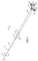
- FIG. 1is a perspective view of a top of a stoma dilator of the present invention, which includes a base dilator, a second, third and fourth dilator, and a sheath;
- FIG. 2is a side elevational view of the stoma dilator of FIG. 1 , showing a base dilator positioned through a patient's skin and abdominal wall and into a patient's stomach;
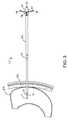
- FIG. 3is a side elevational view similar to FIG. 2 , but showing two additional dilators positioned over the base dilator;
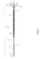
- FIG. 4is a side elevational view of the sheath of the stoma dilator positioned through the stoma, the base dilator and plurality of dilators removed from within the sheath;
- FIG. 5is a side elevational view of the distal ends and stops provided on each dilator which cooperate to provide a taper of all of the dilators of the stoma dilator;
- FIG. 6is a partial sectional view of FIG. 1 , showing the dilator positioner
- FIG. 7is a sectional view of FIG. 1 , taken along lines 7 - 7 ;
- FIG. 8is a side elevational view of the sheath, showing the handles splitting the sheath into two parts to permit the sheath to be peeled away from a device inserted therein;
- FIG. 9is a sectional view similar to FIG. 7 , but showing a stoma dilator having a base dilator and a second, third, fourth and fifth dilators, the dilators deployed toward the distal end of the first or base dilator, thereby forming a continuous taper and illustrating the deployment desired to form a tissue opening or stoma; and
- FIG. 10is a partial sectional view of FIG. 9 , taken along line 10 .
- the stoma dilator 10includes an introductory or base elongated base or first dilator 12 which includes an first introducer end or first end 14 , a proximal end or tail end 16 ( FIGS. 6 and 7 ), and an elongated tubular body 18 .
- the base or first dilator 12also includes a tapered shoulder 20 .
- the shoulder 20is formed between the introducer end 14 and intermediate body 18 . This shoulder 20 extends or tapers outward from a small diameter of the introducer first end 14 to the larger diameter of the elongated tubular body 18 .
- a ring or stop 22is positioned to extend radially outwardly at the junction of the shoulder 20 and the tubular body 18 .
- An opening 24( FIG. 6 ) extends through the length of the base dilator 12 .
- the openingis sized to permit the dilator 10 , and particularly, the base dilator 12 , to be positioned over a guide wire (not shown) which is disposed into a desired tissue target, such as, but not by way of limitation, a hollow organ.
- the guide wirepermits the base dilator 12 , which is the smallest diameter in the series of telescoping tubes contained in the stoma dilator 10 , to be positioned over the wire and through the tissue opening and into the target tissue, for example, a patient's stomach.
- the base dilator 12has a length 26 ( FIG. 7 ) which is desirably longer than the other tubes comprising the stoma dilator 10 , to permit this initial introduction into the stomach.
- the stoma dilatordesirably, but not by way of limitation, includes four additional dilators, namely, a second dilator 30 , a third dilator 32 , and a fourth dilator 34 .
- a fifth dilator 36is illustrated only in FIGS. 9 and 10 .
- These dilatorsare coaxially stacked on the base dilator 12 , so that each may be telescopically moved into position in a tissue dilating procedure. All dilators 12 , 30 , 32 , 34 and 36 used in the stoma dilator 10 are positioned in a longitudinal coaxial alignment.
- Each of the dilators 30 , 32 , 34 and 36respectively, include, similar to the base or first dilator 12 , a first end 14 , a proximal end or tail end 16 , and an elongated tubular body 18 .
- Each of the second, third, fourth and fifth dilators 30 , 32 , 34 and 36respectively, also include a tapered shoulder 20
- the third, fourth, and fifth dilators 32 , 34 , and 36include an internal ring or stop 37 positioned near a proximal end or tail end 14 thereof ( FIGS. 6 , 9 and 10 ).
- An opening 24extends through each second, third, fourth and fifth dilators 30 , 32 , 34 and 36 .
- Each of the first, second, third, fourth and fifth dilators 12 , 30 , 32 , 34 and 36having an outer surface 38 which defines an outer diameter, as shown in FIGS. 1-3 , 5 and 6 .
- Each outer surface 38 of the dilators 12 , 30 , 32 , 34 and 36have a an outer diameter which is slightly larger than a diameter of an inner surface 40 of a dilator which is disposed at least partially over it.
- the inner surface 40 of the base or first dilator 12has a in inner surface 40 which has a diameter large enough to moveably and slideably accept a guide wire therethrough (not shown).
- the second dilator 30has an inner surface 40 which has a diameter large enough to permit the base or first dilator 12 to slidingly move therethrough. Accordingly, the same is true for the relationship between the second and third 30 and 32 dilators, the third and fourth dilators 32 and 34 , and the fourth and fifth dilators 34 and 36 .
- the inner diameter of the dilatorsis desirably large enough to slide over the dilator positioned next to its inner surface 40 , that is, the second dilator 30 .
- the distal end 14 of each dilator 12 , 30 , 32 , 34 , 36is formed to flush its underlying dilator because it is undesirable to have enough space that blood, or other bodily fluids enter this space.
- the base or first dilator 12provides a primary support and operates as a mounting base for each additional elongated, tubular dilators 30 , 32 , 34 and 36 which are telescopically positioned around the base or first dilator.
- the base or first dilator 12is shown in FIG. 1 positioned through a patient's skin 42 and into a patient's stomach 44 .
- the tubular body 18is structured to have a uniform diameter and outer surface 38 .
- the taper between the first end 14 and the tubular body 18enables gradual a dilation of tissue. Accordingly, each successive dilator 30 , 32 , 34 , 36 has a cooperating taper which provides a continuous taper ( FIG.
- each dilator 30 , 32 , 34 and 36prevents one of the dilators to advance over the other when positioned inside of a patient's body. Therefore, health care provider's are more easily aware of the position of each dilator 12 , 30 , 32 , 24 , 36 with respect to the tissue target of the dilator 10 .
- the tail end 16 of the base or first dilator 12differs from the tail end 16 of the other dilators 30 , 32 , 34 and 36 , as shown in FIGS. 1 , 6 and 7 .
- a hub assemblyis disposed thereon, and it includes a hub 46 having an opening 47 therethrough in communication with the opening 24 formed in the base or first dilator 12 .
- the hub 46desirably has an ISO female luer lock positioned on the tail end 16 of the base or first dilator 12 .
- the hub 46has a pair of opposing wings 48 positioned opposite each other on the hub 46 , which aid in grasping the hub 46 . Each wing 48 has a groove 49 therein.
- a base 50 of the hub 46is positioned therebelow.
- the hub assemblyalso includes a dilator positioner.
- a portion of the dilator positionerincludes a plurality of radially-disposed bars which are positioned in separate groups on the base or first dilator 12 below the hub 46 , as illustrated in FIGS. 6 , 7 , 9 and 10 .
- the separate groups of barsare desirably spaced-apart from the wings 48 of the hub 46 via a groove 51 which is adjacent to the base 50 .
- the groups of radially-disposed barsare axially aligned on a portion of the outer surface 38 of the base or first dilator 12 , and are separated into separate groups, each group having a different diameter.
- the first group of bars or first bars 52comprises, for example, but not by way of limitation, four bars, which have a relatively largest outer diameter of the group.
- the second group of bars or second bars 54are spaced-apart from the first bars via a groove 56 .
- the second bars 54have a relatively intermediate diameter, relative to a third group of bars or third bars 58 .
- the third bars 58have a smallest diameter, relative to the second bars 54 and the first bars 52 .
- the third bars 58are spaced-apart from the second bars 54 via a groove 60 .
- An end 62 of the dilator positioneris also desirably utilized; the end 62 is positioned next to the third bars 58 .
- Each set of grooves 51 , 56 , and 60may include bars or other protuberances, but will be smaller in outer diameter than the bars 52 , 54 or 58 which are next to it.
- the proximal ends or tail ends 16 of the third, fourth and fifth dilators 32 , 34 , 36each desirably have an inner radial ring or stop 37 formed near the tail end 16 on an inner surface 40 thereof. These stops 37 cooperate with the end 62 and the first, second and third bars 52 , 54 , 58 to retain the second, third, fourth and fifth dilators 30 , 32 , 34 , 36 on the hub or base dilator 12 in an undeployed position and to prevent them from being deployed prematurely, and are a part of the dilator positioner.
- the undeployed position of the second, third, fourth and fifth dilators 30 , 32 , 34 , 36is illustrated in FIGS.
- FIGS. 5 , 9 and 10the deployed position of the second, third, fourth and fifth dilators 30 , 32 , 34 , 36 is illustrated in FIGS. 5 , 9 and 10 .
- dilators on a hubcan be deployed prematurely, when an underlying dilator is deployed, and the friction between dilators can cause one or more of the overlying dilators to also be deployed.
- the components of the dilator positionerprevents this occurrence.
- a portion of the dilator positionerassist in holding the dilators in a staggered coaxial alignment.
- the end 62contacts the proximal or tail end 16 of the second dilator 30 into a telescoping position over the first or base dilator 12 , and prevents positioning of the second dilator 30 closer to the hub 46 .
- the third bars 58position the stop 37 on the third dilator 32 so that it contacts the groove 60 and the proximal or tail end 16 of the third dilator 32 contacts the second bars 54 to position the third dilator 32 in a telescoping position over the second dilator 30 and to prevent movement of the third dilator 32 toward the hub 46 .
- the stop 37 on the fourth dilator 34is positioned in the groove 56 between the second bars 54 and the first bars 52 .
- the proximal or tail end 16 of the fourth dilator 34is positioned against the first bars 52 to position the fourth dilator 34 in a telescoping position over the third dilator 32 and to prevent movement of the fourth dilator 34 toward the hub 46 .
- the dilator positionerprevents one or more of the smaller dilators from getting frictionally retained within one of the larger dilators, so that all dilators are readily and sequentially positioned and that at least a portion of the distal or first end 14 of each dilator 12 , 30 , 32 , 34 , 36 ( FIGS. 9 and 10 ) is accessible.
- the dilator positioneralso holds the dilators 30 , 32 , 34 , 36 in place, so that one or more of the dilators cannot be removed or fall off of a proximal end of the stoma dilator 10 .
- the dilator positionervia the bars 52 , 54 , 58 and grooves 51 , 56 , 60 , as well as the radially positioned stops 37 near the proximal ends 16 of the dilators 30 , 32 , 34 and 36 permits proper deployment of the dilators, as illustrated in FIGS. 6 , 9 and 10 .
- the components of the dilator positionact to present the dilators in a staggered coaxial alignment, so that the distal end of each dilator presents at least portion that may be grasped by a health care practitioner and moved for tissue dilation.
- the stoma dilator 10desirably includes a sheath 66 which is positioned in coaxial alignment over the fourth dilator 34 ( FIGS. 1-8 ) or the fifth dilator 36 ( FIGS. 9 and 10 ). It will be understood that the sheath 66 is desirably positioned over the outer-most dilator of the plurality of dilators.
- the sheath 66includes a distal end 68 and an opposing proximal end 70 .
- a longitudinal cylindrical tube or sheath body 72is positioned therebetween.
- the sheath body 72has an opening therethrough and an inner diameter defined by an inner surface 74 that is only slightly larger than an outer diameter of the outer surface 38 of the outer most dilator.
- the diameter size of the sheath 66facilitates movement of the sheath over the outer surface 38 of the outermost dilator, but does not facilitate movement of bodily fluids through the space between the sheath 66 and the outermost dilator.
- the proximal end 70 of the sheath 66includes a pair of handles 78 which are positioned in a spaced-apart and opposing relationship on the sheath 66 .
- Each handle 78includes a flange 80 positioned adjacent the hub 46 and a recess 82 positioned thereunder. A portion of each flange 78 extends into the groove 49 next to the base 50 of the hub 46 , while a portion of the base 50 extends into the recess 82 positioned below each flange 80 of each handle 78 .
- These componentscooperate to hold the sheath 66 in an engaged, fixed, non-deployed position against the hub 66 relative to the dilators 12 , 30 , 32 , 34 ( FIGS.
- the sheath 66may be coupled to a portion of the stoma dilator 10 via a releasable adhesive (such as a pressure sensitive adhesive) and so forth (not shown). If coupled via any adhesive, rotation of the sheath 66 desirably will release the release the adhesive, permitting the sheath 66 to be moved.
- a releasable adhesivesuch as a pressure sensitive adhesive
- the sheath 66may be placed through the stoma or tissue opening, and the stoma dilator 10 may be removed.
- the sheath 66may permit a device to be positioned therethrough via its opening.
- the sheathmay be peeled away from such a device placed therethrough, to permit at least a portion of such a device to be retained in the tissue opening or stoma.
- the sheath 66may be removed by pushing the handles 78 toward the distal end 68 of the sheath 66 , which causes the sheath 66 to begin to separate at the proximal end 70 , and down the sheath body 72 between the handles 78 . This separation extends down the body 72 to the distal end 68 , to permit the sheath 66 to be withdrawn from around such a device.
- a stoma dilator 10is desirably provided, as shown in FIG. 1 .
- a wiremay desirably be disposed via a lumen of an introducer needle (not shown) through a patient's skin 42 and into a target organ, such as a patient's stomach 44 . The needle is withdrawn and the wire is desirably retained in place (not shown).
- the base or first dilator 12is desirably positioned over the wire (not shown), and it is moved by manual manipulation of a health care practitioner to follow the wire through the patient's skin 42 and into the stomach 44 to begin the creation of the tissue opening or stoma ( FIG. 2 ).
- the next-sized dilatori.e., the second dilator 30 , is then manually moved over the base or first dilator 12 , until the distal end or first end 14 contacts the stop 22 on the first end 14 of the first or base dilator 12 .
- the third dilator 32is manually moved over the second dilator 30 , until the stop 37 near the proximal end or tail end 16 of the third dilator 32 contacts the proximal end or tail end 16 of the second dilator 30 , as shown in FIGS. 9 and 10 .
- the fourth dilator 34is then, in sequence, manually disposed over the third dilator 32 , until the stop 37 near the proximal or tail end 16 of the fourth dilator 34 contacts the proximal end or tail end 16 of the third dilator 34 .
- a fifth dilator 36is present, as illustrated in FIGS.
- Another portion of the dilator positionernamely, the stop 22 on the base dilator 12 and the stops 37 on at least some of the plurality of dilators, in this instance, the third, fourth and fifth dilators 32 , 34 and 36 , cooperate as the other portion of the dilator positioner to permit proper deployment of the dilators toward and adjacent the distal or first end 14 of the base dilator 12 , so that each dilator has a distal end 14 which is graspable by a health care practitioner to move into a cooperative deployment, as illustrated in FIGS. 9 and 10 , and which provides a continuous taper of the distal end of the stoma dilator 10 , as shown in FIG. 5 .
- the stops 22 and 37operate such that one dilator of the plurality of dilators, in this instance, the second dilator 30 , does not have and does not need a stop to be held in proper alignment in a deployed position.
- the sheath 66is rotated ninety (90) degrees with respect to the hub 46 to release the sheath 66 from it's releasable connection with the hub 46 . That is, the portion of the base 50 of the hub 46 is moved out of the recess 82 below the flange 80 , and the portion of the flange 80 of the handle 78 is moved out of the groove 49 next to the base 50 . This action moves the referenced components in into a non-engaged position, thereby permitting movement of the sheath 66 over the outer surface 38 of the outermost dilator.
- the distal end 68 of the sheathis blunted and not tapered, so that it may extend past one or more of the first ends 14 of the first, second, third, fourth or fifth dilators 12 , 30 , 34 , 36 .
- the stoma dilator 10that is, the base dilator 12 and the plurality of dilators 30 , 32 , 34 ( FIGS. 1-8 ) and 36 ( FIGS. 9 and 10 ), is removed by moving it out of the tissue opening.
- the wireis desirably removed at least with the stoma dilator 10 (not shown).
- the sheath 66is desirably left in position in the stoma ( FIG. 4 ).
- a devicesuch as, but not by way of limitation, an enteral feeding tube, may be positioned through the sheath 66 and at least a portion of the device may be positioned in the stomach and secured through normal means, such as inflation of a bolster at the distal end thereof (not shown).
- the handles 78 of the sheath 66 or pushed toward the distal end 68 of the sheath 66so that the proximal end 70 of the sheath 66 will start splitting apart between the handles 78 ( FIG. 8 .
- the sheath 66will split apart from the proximal end 70 to the distal end 68 , providing two separate portions, each retaining a handle (not shown).
- the sheath 66is desirable withdrawn from the tissue opening or stoma and discarded.
- the opening 47 through the hub and through the base or first dilator 12permits removal of the wire (not shown) at any time during the procedure, as well as luminal access to the stomach, for purposes of injecting fluids or contrast media, or withdrawing fluid from the stomach 44 .
- the hub 46may also include a Tuohy-Borst connector (not shown). The Tuohy-Borst connector may be tightened to lock the dilator onto the guide wire and prevent fluids from escaping through the opening 47 in the hub 46 and the opening 24 in the base or first dilator 12 .
- the stoma dilator 10is desirably constructed from a medical grade plastic. More desirably, the stoma dilator 10 may be constructed from high density polyethylene. It will be understood that the stoma dilator 10 may be constructed in different sizes, to a to accommodate tissue openings into different organs or blood vessels in a human body. For use in a gastrostomy, however, desirably the base or first dilator 12 is an 8 French size.
- the second dilator 30is desirably a 12 French size
- the third dilator 32is desirably a 16 French size
- the fourth dilator 34is desirably a 20 French size
- the fifth dilator 36is desirably a 24 French size.
- the sheathis desirably a 26 French size when a fifth dilator is used; it will be appreciated that a smaller size sheath will be used over the fourth dilator if only four dilators are present.
- the peel-away sheath and hub assemblyare desirably constructed from a medical grade high density polyethylene.
Landscapes
- Health & Medical Sciences (AREA)
- Life Sciences & Earth Sciences (AREA)
- Animal Behavior & Ethology (AREA)
- General Health & Medical Sciences (AREA)
- Veterinary Medicine (AREA)
- Engineering & Computer Science (AREA)
- Biomedical Technology (AREA)
- Heart & Thoracic Surgery (AREA)
- Public Health (AREA)
- Surgery (AREA)
- Pathology (AREA)
- Molecular Biology (AREA)
- Medical Informatics (AREA)
- Nuclear Medicine, Radiotherapy & Molecular Imaging (AREA)
- Anesthesiology (AREA)
- Hematology (AREA)
- Media Introduction/Drainage Providing Device (AREA)
- Orthopedics, Nursing, And Contraception (AREA)
- Surgical Instruments (AREA)
- Absorbent Articles And Supports Therefor (AREA)
Abstract
Description
Claims (9)
Priority Applications (16)
| Application Number | Priority Date | Filing Date | Title |
|---|---|---|---|
| US11/848,502US8211136B2 (en) | 2007-08-31 | 2007-08-31 | Stoma dilator |
| KR1020107003958AKR101515090B1 (en) | 2007-08-31 | 2008-06-19 | Stoma dilator |
| PCT/IB2008/052422WO2009027859A1 (en) | 2007-08-31 | 2008-06-19 | Stoma dilator |
| CA2697873ACA2697873C (en) | 2007-08-31 | 2008-06-19 | Stoma dilator |
| PT08789152TPT2182863E (en) | 2007-08-31 | 2008-06-19 | Stoma dilator |
| EP08789152AEP2182863B1 (en) | 2007-08-31 | 2008-06-19 | Stoma dilator |
| AU2008291776AAU2008291776B2 (en) | 2007-08-31 | 2008-06-19 | Stoma dilator |
| CN2008801050903ACN101795631B (en) | 2007-08-31 | 2008-06-19 | Stoma dilator |
| RU2010111553/14ARU2472459C2 (en) | 2007-08-31 | 2008-06-19 | Stoma extender |
| BRPI0815447ABRPI0815447A2 (en) | 2007-08-31 | 2008-06-19 | stoma dilator |
| MX2010002045AMX2010002045A (en) | 2007-08-31 | 2008-06-19 | Stoma dilator. |
| ES08789152TES2383629T3 (en) | 2007-08-31 | 2008-06-19 | Stoma dilator |
| JP2010522477AJP5431328B2 (en) | 2007-08-31 | 2008-06-19 | Stoma dilator |
| CA2870212ACA2870212C (en) | 2007-08-31 | 2008-06-19 | Stoma dilator |
| DK08789152.9TDK2182863T3 (en) | 2007-08-31 | 2008-06-19 | stoma |
| US13/487,815US8795311B2 (en) | 2007-08-31 | 2012-06-04 | Stoma dilator |
Applications Claiming Priority (1)
| Application Number | Priority Date | Filing Date | Title |
|---|---|---|---|
| US11/848,502US8211136B2 (en) | 2007-08-31 | 2007-08-31 | Stoma dilator |
Related Child Applications (1)
| Application Number | Title | Priority Date | Filing Date |
|---|---|---|---|
| US13/487,815DivisionUS8795311B2 (en) | 2007-08-31 | 2012-06-04 | Stoma dilator |
Publications (2)
| Publication Number | Publication Date |
|---|---|
| US20090062832A1 US20090062832A1 (en) | 2009-03-05 |
| US8211136B2true US8211136B2 (en) | 2012-07-03 |
Family
ID=39877772
Family Applications (2)
| Application Number | Title | Priority Date | Filing Date |
|---|---|---|---|
| US11/848,502Active2029-04-19US8211136B2 (en) | 2007-08-31 | 2007-08-31 | Stoma dilator |
| US13/487,815Active2027-11-04US8795311B2 (en) | 2007-08-31 | 2012-06-04 | Stoma dilator |
Family Applications After (1)
| Application Number | Title | Priority Date | Filing Date |
|---|---|---|---|
| US13/487,815Active2027-11-04US8795311B2 (en) | 2007-08-31 | 2012-06-04 | Stoma dilator |
Country Status (14)
| Country | Link |
|---|---|
| US (2) | US8211136B2 (en) |
| EP (1) | EP2182863B1 (en) |
| JP (1) | JP5431328B2 (en) |
| KR (1) | KR101515090B1 (en) |
| CN (1) | CN101795631B (en) |
| AU (1) | AU2008291776B2 (en) |
| BR (1) | BRPI0815447A2 (en) |
| CA (2) | CA2870212C (en) |
| DK (1) | DK2182863T3 (en) |
| ES (1) | ES2383629T3 (en) |
| MX (1) | MX2010002045A (en) |
| PT (1) | PT2182863E (en) |
| RU (1) | RU2472459C2 (en) |
| WO (1) | WO2009027859A1 (en) |
Cited By (2)
| Publication number | Priority date | Publication date | Assignee | Title |
|---|---|---|---|---|
| US20080086161A1 (en)* | 2006-05-05 | 2008-04-10 | I-Flow Corporation | Soft tissue tunneling device |
| US20170224963A1 (en)* | 2014-03-03 | 2017-08-10 | The Spectranetics Corporation | Dilator sheath set |
Families Citing this family (36)
| Publication number | Priority date | Publication date | Assignee | Title |
|---|---|---|---|---|
| US7309344B2 (en)* | 2002-12-20 | 2007-12-18 | Ethicon Endo-Surgery, Inc. | Transparent dilator device and method of use |
| US20090163942A1 (en)* | 2007-12-20 | 2009-06-25 | Cuevas Brian J | Tracheostomy punch dilator |
| USD605759S1 (en)* | 2008-06-27 | 2009-12-08 | Kimberly-Clark Worldwide, Inc. | Dilator handle |
| JP5439886B2 (en)* | 2009-03-23 | 2014-03-12 | 住友ベークライト株式会社 | Medical dilator |
| AU2010334552B2 (en) | 2009-12-27 | 2014-04-17 | Covidien Lp | Medical device |
| JP2011206179A (en)* | 2010-03-29 | 2011-10-20 | Fuji Systems Corp | Gastrostomy instrument and gastrostomy method |
| US9125800B2 (en)* | 2010-09-27 | 2015-09-08 | Avent, Inc. | Stoma length indicator assembly and positioning system |
| JP5199434B2 (en)* | 2011-09-28 | 2013-05-15 | クリエートメディック株式会社 | Dilator |
| EP2827935B1 (en)* | 2012-03-18 | 2018-01-10 | Traumatek Solutions B.V. | Devices for endovascular access and therapy |
| EP2830515A2 (en)* | 2012-03-30 | 2015-02-04 | Koninklijke Philips N.V. | Nested cannula tips |
| US20140277195A1 (en)* | 2013-03-12 | 2014-09-18 | Warsaw Orthopedic, Inc. | Surgical instrument and method |
| CN103735297B (en)* | 2013-11-29 | 2016-06-01 | 冯清亮 | A kind of classification expansion through skin trachea incising apparatus |
| RU2549489C1 (en)* | 2013-12-16 | 2015-04-27 | государственное бюджетное образовательное учреждение высшего профессионального образования "Северо-Осетинская государственная медицинская академия" Министерства здравоохранения Российской Федерации | Method for colonic decompression in obturation obstruction |
| US20150231369A1 (en)* | 2014-02-20 | 2015-08-20 | Boston Scientific Scimed, Inc. | Peelable sheath |
| WO2015171390A1 (en) | 2014-05-07 | 2015-11-12 | Avent, Inc. | Medical port with replaceable catheter |
| US10190334B2 (en) | 2015-11-03 | 2019-01-29 | Schlage Lock Company Llc | Adjustable length cable |
| WO2017147493A1 (en) | 2016-02-24 | 2017-08-31 | Incept, Llc | Enhanced flexibility neurovascular catheter |
| WO2018048538A1 (en)* | 2016-09-08 | 2018-03-15 | Napolez Adolfo | Gastrostomy tube reinsertion device |
| EP3538195A4 (en)* | 2016-11-09 | 2020-11-04 | Suresh Subraya Pai | Devices and methods for the dilation of sinus ostia and other body passages |
| AU2019262972B2 (en) | 2018-05-01 | 2025-02-27 | Incept, Llc | Devices and methods for removing obstructive material from an intravascular site |
| WO2019246304A1 (en)* | 2018-06-20 | 2019-12-26 | C.R. Bard, Inc. | Introducer tool and methods thereof |
| US11471582B2 (en) | 2018-07-06 | 2022-10-18 | Incept, Llc | Vacuum transfer tool for extendable catheter |
| US11766539B2 (en) | 2019-03-29 | 2023-09-26 | Incept, Llc | Enhanced flexibility neurovascular catheter |
| CN211856471U (en) | 2019-08-22 | 2020-11-03 | 贝克顿·迪金森公司 | Quantitative testing system for echogenicity of echogenic medical instrument |
| CN211884905U (en) | 2019-08-22 | 2020-11-10 | 贝克顿·迪金森公司 | Balloon dilatation catheter and balloon thereof |
| CN112401971B (en) | 2019-08-23 | 2025-09-09 | 贝克顿·迪金森公司 | Stone extraction for percutaneous nephroscope surgical design kit |
| EP4076611A4 (en) | 2019-12-18 | 2023-11-15 | Imperative Care, Inc. | Methods and systems for treating venous thromboembolic disease |
| US11638637B2 (en) | 2019-12-18 | 2023-05-02 | Imperative Care, Inc. | Method of removing embolic material with thrombus engagement tool |
| US20230248502A1 (en) | 2019-12-18 | 2023-08-10 | Imperative Care, Inc. | Sterile field clot capture module for use in thrombectomy system |
| KR102476456B1 (en) | 2020-06-19 | 2022-12-12 | 주식회사 킴스바이오 | Ureter Access Sheath with Length-adjustable structure |
| KR102489861B1 (en) | 2020-10-23 | 2023-01-17 | 주식회사 킴스바이오 | catheter with flexible units |
| CN113082458B (en)* | 2021-03-24 | 2024-05-28 | 宁波韦科医疗科技有限公司 | Sheath-free guide catheter device with good stability |
| US20220409234A1 (en)* | 2021-06-23 | 2022-12-29 | Medos International Sarl | Serial dilation system |
| US20230052862A1 (en) | 2021-08-12 | 2023-02-16 | Imperative Care, Inc. | Sterile packaging assembly for robotic interventional device |
| USD1077996S1 (en) | 2021-10-18 | 2025-06-03 | Imperative Care, Inc. | Inline fluid filter |
| US12171917B1 (en) | 2024-01-08 | 2024-12-24 | Imperative Care, Inc. | Devices for blood capture and reintroduction during aspiration procedure |
Citations (30)
| Publication number | Priority date | Publication date | Assignee | Title |
|---|---|---|---|---|
| US4449532A (en) | 1980-07-08 | 1984-05-22 | Karl Storz | Dilator to facilitate endoscope insertion into the body |
| US4581025A (en) | 1983-11-14 | 1986-04-08 | Cook Incorporated | Sheath |
| US4772266A (en) | 1987-05-04 | 1988-09-20 | Catheter Technology Corp. | Catheter dilator/sheath assembly and method |
| US4862891A (en) | 1988-03-14 | 1989-09-05 | Canyon Medical Products | Device for sequential percutaneous dilation |
| US4895564A (en)* | 1988-06-08 | 1990-01-23 | Farrell Edward M | Percutaneous femoral bypass system |
| EP0383426A1 (en) | 1989-01-31 | 1990-08-22 | Cook Incorporated | Recessed dilator-sheath assembly and method for making same |
| US5074846A (en) | 1990-09-13 | 1991-12-24 | Abbott Laboratories | Stoma creator gastrostomy device and method for placement of a feeding tube |
| US5098392A (en) | 1991-06-28 | 1992-03-24 | Fleischhacker John J | Locking dilator for peel away introducer sheath |
| WO1992008513A1 (en) | 1990-11-20 | 1992-05-29 | Interventional Thermodynamics, Inc. | Tension guide and dilator |
| US5139486A (en) | 1991-01-02 | 1992-08-18 | Gerald Moss | Dilator/introducer for percutaneous gastrostomy |
| WO1992020399A1 (en) | 1991-05-17 | 1992-11-26 | Innerdyne Medical, Inc. | Radially expandable dilator |
| US5318543A (en) | 1992-10-08 | 1994-06-07 | Abbott Laboratories | Laparoscopic jejunostomy instrumentation kit |
| US5499975A (en)* | 1989-01-31 | 1996-03-19 | Cook Incorporated | Smooth transitioned dilator-sheath assembly and method |
| US5536255A (en) | 1994-10-03 | 1996-07-16 | Moss; Gerald | Dilator/introducer apparatus for percutaneous gastrostomy |
| WO1999017665A1 (en) | 1997-10-03 | 1999-04-15 | Boston Scientific Corporation | Apparatus and method for percutaneous placement of gastro-intestinal tubes |
| WO2002087678A1 (en) | 2001-04-26 | 2002-11-07 | Medtronic, Inc. | Percutaneous medical probe and flexible guide wire |
| EP0935974B1 (en) | 1998-02-11 | 2003-10-08 | Porges | Telescopic device to dilate a body vessel |
| US20030208220A1 (en) | 2002-05-06 | 2003-11-06 | Worley Seth J. | Telescopic, peel-away introducer and method of using the same |
| WO2004019760A2 (en) | 2002-08-29 | 2004-03-11 | Medical Components, Inc. | Releasably locking dilator and sheath assembly |
| US20050080443A1 (en) | 2003-08-26 | 2005-04-14 | Medicinelodge, Inc. | Bodily tissue dilation systems and methods |
| US20060004398A1 (en)* | 2004-07-02 | 2006-01-05 | Binder Lawrence J Jr | Sequential dilator system |
| US20060030872A1 (en) | 2004-08-03 | 2006-02-09 | Brad Culbert | Dilation introducer for orthopedic surgery |
| WO2006017507A2 (en) | 2004-08-03 | 2006-02-16 | Triage Medical | Telescopic percutaneous tissue dilation systems and related methods |
| US20060052749A1 (en) | 2004-09-07 | 2006-03-09 | Robert Moyer | Peel-away introducer and method for making the same |
| US20060092694A1 (en) | 2004-10-28 | 2006-05-04 | Samsung Electronics Co., Ltd. | Phase change memory device and method of operating the same |
| US20060203430A1 (en) | 2005-01-31 | 2006-09-14 | Infineon Technologies Ag | Method and device for driving solid electrolyte cells |
| US20060217664A1 (en) | 2004-11-15 | 2006-09-28 | Hattler Brack G | Telescoping vascular dilator |
| WO2007000159A1 (en) | 2005-06-27 | 2007-01-04 | William Cook Europe Aps | A dilator for performing a percutaneous medical procedure |
| WO2007033341A1 (en) | 2005-09-14 | 2007-03-22 | Boston Scientific Scimed, Inc. | Percutaneous endoscopic jejunostomy access needle |
| US20070099405A1 (en) | 2005-11-03 | 2007-05-03 | Cswitch Corporation | Methods for fabricating multi-terminal phase change devices |
Family Cites Families (7)
| Publication number | Priority date | Publication date | Assignee | Title |
|---|---|---|---|---|
| SU1153900A1 (en)* | 1982-04-23 | 1985-05-07 | Винницкий медицинский институт им.Н.И.Пирогова | Apparatus for biopsy |
| JPS60174159A (en)* | 1984-02-20 | 1985-09-07 | オリンパス光学工業株式会社 | Expander |
| GB2163351B (en)* | 1984-08-20 | 1987-08-19 | Craig Med Prod Ltd | Loop ostomy appliance |
| JPS61209647A (en)* | 1985-03-14 | 1986-09-17 | 須广 久善 | Incision opening retractor for connecting blood vessel |
| JP2001314515A (en) | 2000-05-12 | 2001-11-13 | Jiima Kk | Medical tearing tube |
| US6706017B1 (en)* | 2000-09-18 | 2004-03-16 | Pavel Dulguerov | Percutaneous ostomy device and method for creating a stoma and implanting a canula |
| US7309344B2 (en)* | 2002-12-20 | 2007-12-18 | Ethicon Endo-Surgery, Inc. | Transparent dilator device and method of use |
- 2007
- 2007-08-31USUS11/848,502patent/US8211136B2/enactiveActive
- 2008
- 2008-06-19ESES08789152Tpatent/ES2383629T3/enactiveActive
- 2008-06-19AUAU2008291776Apatent/AU2008291776B2/enactiveActive
- 2008-06-19CNCN2008801050903Apatent/CN101795631B/enactiveActive
- 2008-06-19PTPT08789152Tpatent/PT2182863E/enunknown
- 2008-06-19RURU2010111553/14Apatent/RU2472459C2/ennot_activeIP Right Cessation
- 2008-06-19WOPCT/IB2008/052422patent/WO2009027859A1/enactiveApplication Filing
- 2008-06-19DKDK08789152.9Tpatent/DK2182863T3/enactive
- 2008-06-19JPJP2010522477Apatent/JP5431328B2/ennot_activeExpired - Fee Related
- 2008-06-19CACA2870212Apatent/CA2870212C/enactiveActive
- 2008-06-19CACA2697873Apatent/CA2697873C/enactiveActive
- 2008-06-19MXMX2010002045Apatent/MX2010002045A/enactiveIP Right Grant
- 2008-06-19EPEP08789152Apatent/EP2182863B1/enactiveActive
- 2008-06-19BRBRPI0815447Apatent/BRPI0815447A2/ennot_activeApplication Discontinuation
- 2008-06-19KRKR1020107003958Apatent/KR101515090B1/ennot_activeExpired - Fee Related
- 2012
- 2012-06-04USUS13/487,815patent/US8795311B2/enactiveActive
Patent Citations (33)
| Publication number | Priority date | Publication date | Assignee | Title |
|---|---|---|---|---|
| US4449532A (en) | 1980-07-08 | 1984-05-22 | Karl Storz | Dilator to facilitate endoscope insertion into the body |
| US4581025A (en) | 1983-11-14 | 1986-04-08 | Cook Incorporated | Sheath |
| US4772266A (en) | 1987-05-04 | 1988-09-20 | Catheter Technology Corp. | Catheter dilator/sheath assembly and method |
| US4862891A (en) | 1988-03-14 | 1989-09-05 | Canyon Medical Products | Device for sequential percutaneous dilation |
| EP0334116A1 (en) | 1988-03-14 | 1989-09-27 | Canyon Medical Products | Device for sequential percutaneous dilation |
| US4895564A (en)* | 1988-06-08 | 1990-01-23 | Farrell Edward M | Percutaneous femoral bypass system |
| EP0383426A1 (en) | 1989-01-31 | 1990-08-22 | Cook Incorporated | Recessed dilator-sheath assembly and method for making same |
| US5499975A (en)* | 1989-01-31 | 1996-03-19 | Cook Incorporated | Smooth transitioned dilator-sheath assembly and method |
| EP0475324A1 (en) | 1990-09-13 | 1992-03-18 | Abbott Laboratories | Stoma creator gastrostomy device for placement of a feeding tube |
| US5074846A (en) | 1990-09-13 | 1991-12-24 | Abbott Laboratories | Stoma creator gastrostomy device and method for placement of a feeding tube |
| WO1992008513A1 (en) | 1990-11-20 | 1992-05-29 | Interventional Thermodynamics, Inc. | Tension guide and dilator |
| US5139486A (en) | 1991-01-02 | 1992-08-18 | Gerald Moss | Dilator/introducer for percutaneous gastrostomy |
| WO1992020399A1 (en) | 1991-05-17 | 1992-11-26 | Innerdyne Medical, Inc. | Radially expandable dilator |
| US5098392A (en) | 1991-06-28 | 1992-03-24 | Fleischhacker John J | Locking dilator for peel away introducer sheath |
| US5318543A (en) | 1992-10-08 | 1994-06-07 | Abbott Laboratories | Laparoscopic jejunostomy instrumentation kit |
| US5536255A (en) | 1994-10-03 | 1996-07-16 | Moss; Gerald | Dilator/introducer apparatus for percutaneous gastrostomy |
| WO1999017665A1 (en) | 1997-10-03 | 1999-04-15 | Boston Scientific Corporation | Apparatus and method for percutaneous placement of gastro-intestinal tubes |
| EP0935974B1 (en) | 1998-02-11 | 2003-10-08 | Porges | Telescopic device to dilate a body vessel |
| WO2002087678A1 (en) | 2001-04-26 | 2002-11-07 | Medtronic, Inc. | Percutaneous medical probe and flexible guide wire |
| US20030208220A1 (en) | 2002-05-06 | 2003-11-06 | Worley Seth J. | Telescopic, peel-away introducer and method of using the same |
| WO2004019760A2 (en) | 2002-08-29 | 2004-03-11 | Medical Components, Inc. | Releasably locking dilator and sheath assembly |
| US20040098020A1 (en)* | 2002-08-29 | 2004-05-20 | Medical Components, Inc. | Releasably locking dilator and sheath assembly |
| US20050080443A1 (en) | 2003-08-26 | 2005-04-14 | Medicinelodge, Inc. | Bodily tissue dilation systems and methods |
| US20060004398A1 (en)* | 2004-07-02 | 2006-01-05 | Binder Lawrence J Jr | Sequential dilator system |
| WO2006017507A2 (en) | 2004-08-03 | 2006-02-16 | Triage Medical | Telescopic percutaneous tissue dilation systems and related methods |
| US20060030872A1 (en) | 2004-08-03 | 2006-02-09 | Brad Culbert | Dilation introducer for orthopedic surgery |
| US20060052749A1 (en) | 2004-09-07 | 2006-03-09 | Robert Moyer | Peel-away introducer and method for making the same |
| US20060092694A1 (en) | 2004-10-28 | 2006-05-04 | Samsung Electronics Co., Ltd. | Phase change memory device and method of operating the same |
| US20060217664A1 (en) | 2004-11-15 | 2006-09-28 | Hattler Brack G | Telescoping vascular dilator |
| US20060203430A1 (en) | 2005-01-31 | 2006-09-14 | Infineon Technologies Ag | Method and device for driving solid electrolyte cells |
| WO2007000159A1 (en) | 2005-06-27 | 2007-01-04 | William Cook Europe Aps | A dilator for performing a percutaneous medical procedure |
| WO2007033341A1 (en) | 2005-09-14 | 2007-03-22 | Boston Scientific Scimed, Inc. | Percutaneous endoscopic jejunostomy access needle |
| US20070099405A1 (en) | 2005-11-03 | 2007-05-03 | Cswitch Corporation | Methods for fabricating multi-terminal phase change devices |
Non-Patent Citations (1)
| Title |
|---|
| Patent Cooperation Treaty Search Report from the International Search Authority, International Application No. PCT/IB2008/052422 dated Mar. 11, 2010. |
Cited By (4)
| Publication number | Priority date | Publication date | Assignee | Title |
|---|---|---|---|---|
| US20080086161A1 (en)* | 2006-05-05 | 2008-04-10 | I-Flow Corporation | Soft tissue tunneling device |
| US9289232B2 (en)* | 2006-05-05 | 2016-03-22 | Avent, Inc. | Soft tissue tunneling device |
| US20170224963A1 (en)* | 2014-03-03 | 2017-08-10 | The Spectranetics Corporation | Dilator sheath set |
| US10653867B2 (en)* | 2014-03-03 | 2020-05-19 | Spectranetics Llc | Dilator sheath set |
Also Published As
| Publication number | Publication date |
|---|---|
| EP2182863B1 (en) | 2012-05-16 |
| CA2870212A1 (en) | 2009-03-05 |
| CA2697873A1 (en) | 2009-03-05 |
| BRPI0815447A2 (en) | 2019-02-26 |
| US20090062832A1 (en) | 2009-03-05 |
| PT2182863E (en) | 2012-07-10 |
| AU2008291776B2 (en) | 2013-06-06 |
| US8795311B2 (en) | 2014-08-05 |
| CA2870212C (en) | 2016-08-30 |
| US20120302837A1 (en) | 2012-11-29 |
| DK2182863T3 (en) | 2012-07-16 |
| CA2697873C (en) | 2015-07-28 |
| JP5431328B2 (en) | 2014-03-05 |
| RU2472459C2 (en) | 2013-01-20 |
| AU2008291776A1 (en) | 2009-03-05 |
| KR20100061451A (en) | 2010-06-07 |
| CN101795631B (en) | 2013-07-10 |
| MX2010002045A (en) | 2010-03-15 |
| JP2010537691A (en) | 2010-12-09 |
| WO2009027859A1 (en) | 2009-03-05 |
| KR101515090B1 (en) | 2015-04-24 |
| ES2383629T3 (en) | 2012-06-22 |
| RU2010111553A (en) | 2011-10-10 |
| EP2182863A1 (en) | 2010-05-12 |
| CN101795631A (en) | 2010-08-04 |
Similar Documents
| Publication | Publication Date | Title |
|---|---|---|
| US8211136B2 (en) | Stoma dilator | |
| US12256898B2 (en) | Introducer sheaths for endoscopes and related methods | |
| US8043261B2 (en) | Method for percutaneously implanting a medical catheter and medical catheter implanting assembly | |
| EP1379180B1 (en) | Apparatus for the insertion of a medical device | |
| US8523818B2 (en) | Enteral feeding assembly with obturator | |
| US8361033B2 (en) | Access needle well-suited for percutaneous implantation in a body lumen | |
| US20100298839A1 (en) | Peelable Sheath and Method of Use | |
| US20120010571A1 (en) | Catheter assemby and method for internally anchoring a catheter in a patient | |
| WO2004002562A2 (en) | Introducer sheath | |
| CA2639938A1 (en) | Surgical tool for performing percutaneous endoscopic gastrostomy | |
| WO2015063497A1 (en) | Trocar and cannula | |
| US20240238164A1 (en) | Retractable low-profile pediatric gastrostomy tube and uses thereof | |
| US11504504B2 (en) | Systems and methods for expanding a catheter | |
| US11304688B2 (en) | Gastrocutaneous closure device |
Legal Events
| Date | Code | Title | Description |
|---|---|---|---|
| AS | Assignment | Owner name:KIMBERLY-CLARK WORLDWIDE, INC., WISCONSIN Free format text:ASSIGNMENT OF ASSIGNORS INTEREST;ASSIGNORS:GRIFFITH, NATHAN CHRISTOPHER;MCMICHAEL, DONALD JAY;REEL/FRAME:020058/0325 Effective date:20071023 | |
| STCF | Information on status: patent grant | Free format text:PATENTED CASE | |
| AS | Assignment | Owner name:AVENT, INC., GEORGIA Free format text:ASSIGNMENT OF ASSIGNORS INTEREST;ASSIGNOR:KIMBERLY-CLARK WORLDWIDE, INC.;REEL/FRAME:034753/0360 Effective date:20141030 | |
| AS | Assignment | Owner name:MORGAN STANLEY SENIOR FUNDING, INC., NEW YORK Free format text:SECURITY INTEREST;ASSIGNOR:AVENT, INC.;REEL/FRAME:035375/0867 Effective date:20150227 | |
| FPAY | Fee payment | Year of fee payment:4 | |
| AS | Assignment | Owner name:CITIBANK, N.A., NEW YORK Free format text:INTELLECTUAL PROPERTY SECURITY INTEREST ASSIGNMENT AGREEMENT;ASSIGNOR:MORGAN STANLEY SENIOR FUNDING, INC.;REEL/FRAME:048173/0137 Effective date:20181029 | |
| MAFP | Maintenance fee payment | Free format text:PAYMENT OF MAINTENANCE FEE, 8TH YEAR, LARGE ENTITY (ORIGINAL EVENT CODE: M1552); ENTITY STATUS OF PATENT OWNER: LARGE ENTITY Year of fee payment:8 | |
| AS | Assignment | Owner name:JPMORGAN CHASE BANK, N.A., AS ADMINISTRATIVE AGENT, ILLINOIS Free format text:SECURITY INTEREST;ASSIGNOR:AVENT, INC.;REEL/FRAME:060441/0445 Effective date:20220624 | |
| AS | Assignment | Owner name:AVANOS MEDICAL SALES, LLC, GEORGIA Free format text:RELEASE BY SECURED PARTY;ASSIGNOR:CITIBANK, N.A.;REEL/FRAME:060557/0062 Effective date:20220624 Owner name:AVENT, INC., GEORGIA Free format text:RELEASE BY SECURED PARTY;ASSIGNOR:CITIBANK, N.A.;REEL/FRAME:060557/0062 Effective date:20220624 | |
| MAFP | Maintenance fee payment | Free format text:PAYMENT OF MAINTENANCE FEE, 12TH YEAR, LARGE ENTITY (ORIGINAL EVENT CODE: M1553); ENTITY STATUS OF PATENT OWNER: LARGE ENTITY Year of fee payment:12 |