US8211113B2 - Prosthesis cutting guide, cutting tool and method - Google Patents
Prosthesis cutting guide, cutting tool and methodDownload PDFInfo
- Publication number
- US8211113B2 US8211113B2US10/176,891US17689102AUS8211113B2US 8211113 B2US8211113 B2US 8211113B2US 17689102 AUS17689102 AUS 17689102AUS 8211113 B2US8211113 B2US 8211113B2
- Authority
- US
- United States
- Prior art keywords
- guide
- guide slots
- instrument
- length
- bone facing
- Prior art date
- Legal status (The legal status is an assumption and is not a legal conclusion. Google has not performed a legal analysis and makes no representation as to the accuracy of the status listed.)
- Expired - Fee Related
Links
- 0C*1=CCCC1Chemical compoundC*1=CCCC10.000description1
Images


Classifications
- A—HUMAN NECESSITIES
- A61—MEDICAL OR VETERINARY SCIENCE; HYGIENE
- A61B—DIAGNOSIS; SURGERY; IDENTIFICATION
- A61B17/00—Surgical instruments, devices or methods
- A61B17/16—Instruments for performing osteoclasis; Drills or chisels for bones; Trepans
- A61B17/1662—Instruments for performing osteoclasis; Drills or chisels for bones; Trepans for particular parts of the body
- A61B17/1675—Instruments for performing osteoclasis; Drills or chisels for bones; Trepans for particular parts of the body for the knee
- A—HUMAN NECESSITIES
- A61—MEDICAL OR VETERINARY SCIENCE; HYGIENE
- A61B—DIAGNOSIS; SURGERY; IDENTIFICATION
- A61B17/00—Surgical instruments, devices or methods
- A61B17/16—Instruments for performing osteoclasis; Drills or chisels for bones; Trepans
- A61B17/1613—Component parts
- A61B17/1615—Drill bits, i.e. rotating tools extending from a handpiece to contact the worked material
- A—HUMAN NECESSITIES
- A61—MEDICAL OR VETERINARY SCIENCE; HYGIENE
- A61B—DIAGNOSIS; SURGERY; IDENTIFICATION
- A61B17/00—Surgical instruments, devices or methods
- A61B17/16—Instruments for performing osteoclasis; Drills or chisels for bones; Trepans
- A61B17/17—Guides or aligning means for drills, mills, pins or wires
- A61B17/1739—Guides or aligning means for drills, mills, pins or wires specially adapted for particular parts of the body
- A61B17/1764—Guides or aligning means for drills, mills, pins or wires specially adapted for particular parts of the body for the knee
- A—HUMAN NECESSITIES
- A61—MEDICAL OR VETERINARY SCIENCE; HYGIENE
- A61B—DIAGNOSIS; SURGERY; IDENTIFICATION
- A61B17/00—Surgical instruments, devices or methods
- A61B17/16—Instruments for performing osteoclasis; Drills or chisels for bones; Trepans
- A61B17/17—Guides or aligning means for drills, mills, pins or wires
- A61B17/1739—Guides or aligning means for drills, mills, pins or wires specially adapted for particular parts of the body
- A61B17/1742—Guides or aligning means for drills, mills, pins or wires specially adapted for particular parts of the body for the hip
- A—HUMAN NECESSITIES
- A61—MEDICAL OR VETERINARY SCIENCE; HYGIENE
- A61B—DIAGNOSIS; SURGERY; IDENTIFICATION
- A61B17/00—Surgical instruments, devices or methods
- A61B17/16—Instruments for performing osteoclasis; Drills or chisels for bones; Trepans
- A61B17/17—Guides or aligning means for drills, mills, pins or wires
- A61B17/1739—Guides or aligning means for drills, mills, pins or wires specially adapted for particular parts of the body
- A61B17/1778—Guides or aligning means for drills, mills, pins or wires specially adapted for particular parts of the body for the shoulder
- A—HUMAN NECESSITIES
- A61—MEDICAL OR VETERINARY SCIENCE; HYGIENE
- A61B—DIAGNOSIS; SURGERY; IDENTIFICATION
- A61B17/00—Surgical instruments, devices or methods
- A61B17/16—Instruments for performing osteoclasis; Drills or chisels for bones; Trepans
- A61B2017/1602—Mills
- A—HUMAN NECESSITIES
- A61—MEDICAL OR VETERINARY SCIENCE; HYGIENE
- A61B—DIAGNOSIS; SURGERY; IDENTIFICATION
- A61B90/00—Instruments, implements or accessories specially adapted for surgery or diagnosis and not covered by any of the groups A61B1/00 - A61B50/00, e.g. for luxation treatment or for protecting wound edges
- A61B90/03—Automatic limiting or abutting means, e.g. for safety
- A61B2090/033—Abutting means, stops, e.g. abutting on tissue or skin
Definitions
- the present inventionrelates generally to the field of orthopaedics, and more particularly, to an implant for use in arthroplasty.
- Joint replacement surgeryis quite common and it enables many individuals to function properly when it would not otherwise be possible to do so. Such patients of joint replacement surgery typically suffer from osteoarthritis or rheumatoid arthritis. Artificial joints usually comprise metallic, ceramic and/or plastic components that are fixed to existing bone.
- Total joint arthroplastyis a well known surgical procedure by which a diseased and/or damaged joint is replaced with a prosthetic joint.
- a typical total joint arthroplastythe adjacent ends of the bones and cartilage comprising the joint are resected and the artificial implants are secured thereto.
- patello femoral arthroplastyWhen only the patellar articular surface and the adjacent groove on the distal end of the femur, the trochlear, with which it articulates, are damaged, replacement of these surfaces is called a patello femoral arthroplasty.
- cartilage and bonewhen installing the components of the prosthetic joint, cartilage and bone must be resected or removed such that the implanted prosthesis has the same surface profile as the surface prior to its resection.
- Such arthroplastythus requires a pocket formed in the bone of a particular shape and depth to provide a location for the prosthesis such that the prosthesis outer-profile replicates that of the pre-resected joint.
- a trochlear implantfor cooperation with a patella prosthesis for a patello femoral arthroplasty.
- the current process for preparing to implant a trochlear prosthesisis to place a template over the femur where the damaged trochlear is located.
- the trochlear groove of the femuris then physically marked with a tool such as a scribe or marking pen which leaves a mark on the bone or cartilage as the scribe or pen is moved about the periphery of the template.
- the traced marks on the distal femurserve as a guide for preparing the pocket for the trochlear implant.
- Osteotomes and hammer plus high-speed rotating burrsare then used to prepare the pocket within the outlined perimeter. This process is very slow and tedious in order to achieve a precise and accurate fit in all dimensions.
- the present inventionis directed to a cutting guide, which is utilized with a rotating cutting tool to create pockets at a specific depth in the bone for a trochlear or similar implant.
- the cutting guideprovides an accurate cut both in the outline shape and in the depth of the cut. Additional cutting paths are made inside the outline shape utilizing the cutting tool so that only a minimal amount of material must be removed between the cutting path.
- a kit for removal of cartilage and bone from a patient to prepare a cavity for receiving a joint prosthesisincludes a guide for cooperation with the bone and a rotatable tool.
- the toolis constrainable by the guide for removal of the bone.
- the guideincludes a first portion thereof cooperable with the tool and a second portion thereof cooperable with the bone.
- a guidefor guiding a rotatable tool for removal of cartilage and bone from a patient to prepare a cavity for receiving a joint prosthesis.
- the guideincludes a first portion thereof cooperable with the tool and a second portion cooperable with the bone.
- a rotatable tooladapted for removal of cartilage and bone from a patient to prepare a cavity for receiving a joint prosthesis.
- the toolis constrainable by the guide for removal of the bone.
- a method for removal of cartilage and bone from a patient to prepare a cavity for receiving a joint prosthesisincludes the steps of providing a guide defining an opening therein, exposing a portion of the bone of the patient, placing the guide in cooperation with the bone, providing a tool adapted for cooperation with the opening, inserting the tool at least partially within the opening, causing the tool to move relatively to the guide, and advancing the tool within the opening to form the bone cavity.
- the technical advantage of the present inventionincludes an improved imprint or location of the pocket for the prosthesis.
- the guideincludes channels positioned about the outer periphery of the guide, which conform to the outer periphery of the pocket for placing for a pocket with an outer periphery that is well defined and accurate.
- the present inventionprovides for an improved and accurate location of the pocket for the prosthesis.
- the toolincludes a collar, which cooperates with the guide when the tool is placed in the channels of the guide.
- the collar on the toolseats against the rim around the channels and provides for an accurate and consistent depth of the pocket for the implant.
- the guideincludes a plurality of spaced apart channels. These channels occupy most of the cross-sectional area of the guide.
- the guidein cooperation with the tool, is used to form most of the pocket for the implant. Only a quick and simple use of a small osteotome to remove the small portions of material remaining after the utilization of the burr tool and guide, is required and that can be quickly accomplished. Therefore, with the rapid use of the guide and the burr tool and the minimal use of the osteotome, the pocket may be prepared very quickly and accurately.
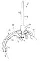
- FIG. 1is a perspective view of a kit according to the present invention including a guide and tool shown in cooperation with each other in accordance with another embodiment of the present invention;
- FIG. 2is a perspective view of the kit of FIG. 1 rotated about 90 degrees from the view of FIG. 4 ;
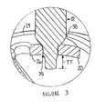
- FIG. 3is an enlarged partial perspective view of the kit of FIG. 2 showing the tool in engagement with the guide in greater detail;
- FIG. 4is a perspective view of a guide according to the present invention in accordance with another embodiment of the present invention.
- FIG. 5is a perspective view of the guide of FIG. 1 rotated about 90 degrees from the view of FIG. 4 ;
- FIG. 6is plan view of the guide of FIG. 4 ;
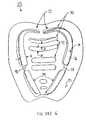
- FIG. 7is a partial plan view of a femur and tibia showing the cuts placed in the femur by the kit of FIGS. 4-6 in accordance with an embodiment of the present invention
- FIG. 8is a partial cross section view of the femur of FIG. 1 along the lines 8 - 8 in the direction of the arrows showing the use of an osteotome to remove bone;
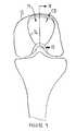
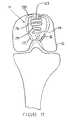
- FIG. 9is a partial plan view of a femur and tibia showing a bone cavity for receiving a joint prosthesis placed in the femur in accordance with an embodiment of the present invention
- FIG. 10is a cross section view of the guide of FIG. 1 along the lines 10 - 10 in the direction of the arrows;
- FIG. 11is plan view of prosthesis for use in the bone cavity of FIG. 9 ;
- FIG. 12is perspective view of the prosthesis of FIG. 11 ;
- FIG. 13is a partial plan view of a femur and tibia showing the prosthesis of FIG. 11 placed in the femur with the leg in extension;
- FIG. 14is a partial plan view of a femur and tibia showing the prosthesis of FIG. 11 placed in the femur with the leg in flexion;
- FIG. 15is a partial plan view of a drill guide installed on a femur for preparing the femur with holes for cooperation with the guide of FIGS. 1 and 2 ;
- FIG. 16is a partial plan view of the drill guide of FIG. 15 along the lines 16 - 16 in the direction of the arrows;
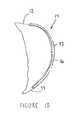
- FIG. 17is a perspective view of a kit according to the present invention including a guide and tool shown in cooperation with each other in accordance with another embodiment of the present invention.
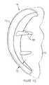
- FIG. 18is a perspective view of the kit of FIG. 15 rotated about 90 degrees from the view of FIG. 15 ;
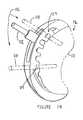
- FIG. 19is a partial plan view of a femur and tibia showing the cuts placed in the femur by the kit of FIGS. 15 and 16 ;
- FIG. 20is a flow diagram of a method of preparing a cavity for prosthesis according to the present invention.
- FIG. 21is a plan view of a peripheral cutting tool guide in accordance to yet another embodiment of the present inventory.
- FIG. 21Ais a plan view of a cutting tool for cooperation with the cutting tool guide of FIG. 21 ;
- FIG. 21Bis a plan view of a pin for cooperation with the cutting tool guide of FIG. 21 ;
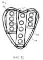
- FIG. 22is a plan view of a drill guide to be used with the periphery cutting tool guide of FIG. 21 ;
- FIG. 22Ais a plan view of a drill for cooperation with the drill guide of FIG. 22 ;
- FIG. 23is a cross sectional view of the drill guide of FIG. 22 along the lines 23 - 23 in the direction of the arrows;
- FIG. 24is a portion plan view of the femur showing the cuts placed in the femur by the kit of FIGS. 21-23 .
- a kit 10 for removal of bone 12for example, a portion of a long bone, from a patient to prepare a bone Cavity 14 for receiving a Joint prosthesis 16 (see FIGS. 11-14 ), is shown.
- the kit 10includes a guide 20 for cooperation with the long bone 12 .
- the kit 10also includes a Rotatable tool 22 , which is constrained by the guide 20 for removal of the bone 12 .
- the guide 20includes a first portion 24 of the guide 20 , which cooperates with the tool 22 .
- the guide 20further includes a second portion 26 of the guide 20 , which cooperates with the long bone 12 .
- the first portion 24 of the guide 20defines a channel 30 through the guide 20 .
- the tool 22is guidable within the channel 30 .
- FIGS. 4 , 5 and 6the guide 20 is shown in greater detail.
- the channels 30are shown on first portion 24 of the guide 20 .
- the channels 30may include arcuate periphery channels 32 as well as Lower periphery channels 34 .
- the periphery channels 32 and 34are, as shown in FIG. 6 , positioned around periphery 36 of the bone cavity 12 as shown in phantom.
- the periphery channels 32 and 34are utilized to guide the tool 22 in a path, which corresponds, to periphery 36 of the bone cavity 12 .
- the periphery channels 32must be spaced from each other.
- the spacingprovides for support lands 40 which are positioned between adjacent periphery channels 32 and 34 .
- the lands 40provide for rigidity to the guide 20 . It should be appreciated that upon utilization of the guide 20 and the tool 22 , the portions of the bone 12 corresponding to the lands 40 on the guide 20 represent portions of the bone, which must be removed by another tool (for example osteotome not shown).
- internal channels 42may be positioned within the guide 20 to provide for removal of additional bone from the bone cavity 12 in an area within the periphery 36 of the bone cavity 12 .
- the internal channels 42are separated from each other.
- the minimal acceptable distance D between adjacent channelsmay vary.
- the distance Dshould be the minimum distance required for sufficient strength of the guide 20 .
- the distancedmay be as little as 0.04 inches.
- the guide 20is shown in position against bone 12 .
- the tool, guide and kit of the present inventionmay be utilized to form a bone cavity in a bone in positions, in addition to the patella femoral joint described in FIGS. 1-6 .
- the guide and tool of the present inventionmay be utilized to form any bone cavity, which may be necessary to provide a mounting location for a prosthetic implant.
- the guide, tool and kit of the present inventionis particularly well suited for utilization in a implant which has a generally uniform thickness and is designed to have an outer contour similar to that of the bone for which it replaces.
- the tool guide and kit of the present inventionmay be well suited for unicondylar knee replacement in which a unicondylar knee having a generally uniform thickness is used to replace the resected bone.
- Other common joints particularly partial implants of the shoulder, knee or hipmay be well suited to the use of the guide tool and kit of the present invention.
- the guide 20is preferably placed over outer periphery 44 of the bone 12 .
- the bone 12is a femur and the guide 20 has an inner periphery 46 on second portion 26 of the guide 20 , which preferably conforms, closely to outer periphery 44 of the bone 12 .
- the tool 20includes a body 50 including a cutting edge 52 on an outer periphery thereof.
- the body 50has a body diameter DD which is slidingly fitted within the channels 30 of the guide 20 .
- the width W of the channels 30is thus slightly larger than the diameter DD of the body 50 .
- the tool 22preferably includes a stop 54 , which limits the motion of the tool 22 in the direction of arrow 56 such that the stop 54 rests against the guide 20 .
- the cutting edge 52 of the tool 22extends inwardly from inner periphery 46 of the guide 20 a distance TT approximately equaled to the thickness TI of the implant (see FIG. 12 ). Since the inner periphery 46 of the guide 20 is shaped to conform to the outer periphery 44 of the bone 12 , the extending of the tool 22 a distance TT below the inner periphery of the guide 20 results in the bone cavity 14 to have a thickness or depth approximately equal to TT.
- implant 16is shown implanted into bone cavity 12 .
- the implant 16may be surgically implanted utilizing the tool guide and kit of the present invention.
- the implant 16may have any suitable shape and may be an implant to replace any joint of the human anatomy or a portion of such a joint. Joints having a generally uniform thickness are particularly well suited for the present invention. Such joints may include unicondylar knee joints or patella femoral joint which is shown in FIGS. 11 through 14 .
- the prosthesis 16is shown implanted on a left femur 12 .
- the prosthesis 16 as shown in FIG. 3is a portion of a patella femoral joint 60 .
- the patella femoral joint (PFJ) 60is used to replace the natural patella when the portion of the knee joint requires a prosthesis due to rheumatoid or osteoarthritis for example.
- the patella femoral joint 60may include a patella component 62 as well as a patella bearing 64 , which is placed between the patella component 62 , and the prosthesis or trochlear component 16 .
- the trochlear component 16 of the patella femoral joint 60is likewise asymmetrical including a smaller medial portion 66 , as well as a larger lateral portion 70 .
- the PFJ trochlear component 16defines an outer periphery 72 thereof.
- the trochlear implant periphery 72is slightly smaller than periphery 36 of the bone cavity 14 . It should be appreciated that the trochlear prosthesis for the right knee is similar and complimentary to the left knee trochlear prosthesis 60 as shown in FIG. 13 .
- the proper position of the trochlear prosthesis 60 with regard to the femur 12may be determined either by surgeon skill, by templating relative to anterior/posterior and medial/lateral x-ray techniques or by computer or other high technology positioning techniques.
- the guide 20must be properly secured in position on the femur 12 .
- a trochlear component drilling guide 74 as shown in FIGS. 15 and 16may be utilized.
- the drilling guide 74 of FIGS. 15 and 16has been utilized in higher art implanting techniques.
- the drilling guide 74when used in prior art implanting techniques, is utilized by first visually positioning the drilling guide 74 in a predetermined appropriate position.
- This drilling guidemay include, among other things, surgeon expertise and x-ray templating.
- the drilling guide 74is positioned in its proper place against femur 12 and held in position while a drill is utilized to form anchor peg holes 76 in the femur 12 .
- a scribe or edgeis formed around outer periphery 80 of the drilling guide 74 so that the scribed portion of the femur may be resected by prior art techniques utilizing for example osteotomes.
- the guide 20may include a first orientation feature for cooperation with an orientation feature on the prosthesis.
- the orientation feature on the prosthesismay be in the form of a peg 82 extending inwardly from inner periphery 46 of the guide 20 .
- the first orientation feature or guide peg 82 of the guidecooperates with an orientation feature on the bone 12 in the form of, for example, one of the anchor peg holes 76 .
- the guide peg 82closely conforms to the anchor peg 76 for an accurate, precise, and snug fit of the guide to the bone 12 .
- a solitary peg 82may be sufficient to orient the guide 20 against the bone 12 , preferably, and referring to FIG. 4 , a pair of guide pegs 82 , which are spaced apart from each other are utilized in the guide 20 . While the prosthesis 16 of FIG. 4 includes two spaced apart anchor pegs 84 , it would be appreciated that additional guide pegs 82 may be utilized to secure the guide 20 of FIG. 2 .
- the rotatable tool 22is shown according to the present invention.
- the rotatable tool 22is adapted for removal of bone 12 from a patient to prepare the bone cavity 14 for receiving joint prosthesis 16 .
- the tool 22is constrainable by the guide 20 for removal of the bone 12 .
- the rotatable toolmay be in the form of a rotating burr tool.
- the tool 22may include the body 50 , which includes cutting edge 52 formed on a periphery thereof.
- a stem 86is operably associated with the body 50 .
- the stop 54is positioned between the body 50 and the stem 86 for cooperation with the guide 20 to limit the movement of the tool 22 in the direction of the arrow 56 .
- FIGS. 7 through 10the bone cavity 14 prepared utilizing the tool guide kit and method of the present invention is shown on a left femur.
- partially formed or completed cavity 14is shown on the femur 12 .
- the partially completed cavity 14includes medial and lateral arcuate periphery grooves 90 which correspond to the arcuate periphery channels 32 of the guide 20 .
- the partially completed cavity 14further includes lower periphery grooves 92 corresponding to the lower periphery channels 34 of the guide 20 .
- the cavity 14may include internal grooves 94 which correspond to the internal channels 42 of the guide 20 .
- lands 96Located between the grooves 90 , 92 and 94 are lands 96 corresponding to lands 40 of the guide 20 .
- a second tool in the form of a chisel like device called an osteotome 98is shown in use to remove the lands 96 from the femur 12 .
- a striking device in the form of a hammer 99may be utilized to remove bone with the osteotome 98 .
- the osteotomeis positioned in one of the grooves, for example, groove 94 and the hammer 98 is struck against the osteotome 98 to remove for example, the land 96 between the peripheral grove 90 and the internal groove 94 .
- the femuris shown with the cavity 14 having been completed, and the lands 96 between the grooves 90 , 92 and 94 (See FIG. 7 ) having been removed.
- the cavity 14has the outer periphery 36 into which the prosthesis 16 may be fitted.
- the cavity 14also has a cavity depth CD which is approximately equal to the groove depth GD (see FIG. 8 ) formed by the tool when making the grooves 90 , 92 and 94 in the femur 12 . It should be appreciated that the groove depth GD is approximately equal to the depth TT of the tool 22 in the guide 20 as shown in FIG. 2 .
- the cavity 14is shown in cross section in the femur 12 .
- the prosthesis 16is shown in phantom within the cavity 14 . It should be appreciated that the surface 93 of the prosthesis 16 is in general alignment with outer periphery 44 of the femur 12 .
- kit 110includes a guide 120 , which cooperates with a tool 122 .
- the tool 122is similar to tool 22 of FIGS. 1 through 6 and includes a stem 186 to which stop 154 is attached. Extending from the stop 154 is a body 150 . At the end of body 150 is a cutting edge 152 for removing bone 12 .
- the tool 122may be substantially similar to the tool 22 of FIGS. 1 through 6 and be made of any suitable, durable material for example a tool steel.
- the guide 120is similar to guide 20 of FIGS. 1 through 6 except that guide 120 includes guide openings 176 and do not include guide pegs 82 as in the guide 20 of FIGS. 1 through 6 .
- the kit 110 of FIGS. 17 and 18further include guide pins 182 which cooperate with the guide openings 176 of the guide 120 (see FIG. 18 ).
- the guide 120When utilizing the guide 120 of FIGS. 17 and 18 , the guide 120 , like the drilling guide 74 of FIGS. 15 and 16 , is positioned utilizing any suitable surgical technique including, for example, a visual alignment of the guide 120 onto the femur or through the utilization of templates, for example, x-ray templates, a computer technique, or any other alignment technique.
- the guide pins 182Once the guide 120 is placed in the proper position on the femur, the guide pins 182 are placed in position through the guide openings 176 in the guide 120 .
- the guide pins 182may be in the form of self drilling pins or connectors and a power tool (not shown) is utilized to secure the connectors or self drilling pins 118 and 128 into the femur 12 . The guide 120 is thereby secured in position in the femur 12 .
- the anchor peg holes 76are left in a unused or unworn condition so that the drilling guide 74 may be installed into the bone cavity 14 after the bone cavity 14 is prepared such that the anchor peg hole 76 remain in pristine condition for an accurate and secure installation of the prosthesis 16 .
- Channels 130are preferably positioned in the guide 120 , and the channels 130 include upper arcuate periphery channels 132 and lower periphery channels 134 which, when utilized with the tool 120 , may cause the tool 122 to form periphery 36 of the cavity 14 .
- the channels 130preferably also include internal channels 142 , similar to channels 42 of the guide 20 of FIGS. 1 through 6 .
- the upper arcuate periphery channels 132 and the lower periphery channels 134are similar to the upper arcuate channels 32 and the lower periphery channels 34 of the guide 20 of FIGS. 1 through 6 .
- a femur 12having a partially formed bone cavity 14 formed on the femur 12 utilizing the guide 120 of FIGS. 17 and 18 .
- the cavity 14includes arcuate periphery grooves 190 and lower periphery grooves 192 , which correspond to the upper arcuate channels 132 and lower arcuate channels 134 .
- the cavity 14also includes internal grooves 194 which correspond to internal channels 142 in the guide 120 .
- Lands 196 in the cavity 14correspond to lands 140 on the guide 120 of FIGS. 17 and 18 . Similar to the cavity 14 formed by the guide 20 of FIGS. 1 through 6 , the lands 196 are similarly removed by an osteotome and hammer (not shown).
- kit 210includes a cutting tool guide 220 which cooperates with a cutting tool 222 .
- the cutting tool 222is similar tool 22 of FIGS. 1-6 and may include a stem 286 254 , is a body 250 . At the end of the body 250 is a cutting edge 252 for removing bone.
- the tool 222may be substantially similar to the tool 22 of FIGS. 1-6 and be made of any suitable, durable material, for example a tool steel.
- the cutting tool guide 220is similar to guide 20 of FIGS. 1-6 except that cutting tool guide 220 includes guide openings 276 and does not include guide pegs 82 as in the guide of FIGS. 1-6 .
- the kit 210 of FIGS. 21-23further includes a guide pin 282 which cooperates with the guide opening 276 of the guide 220 .
- the guide 220When utilizing the cutting tool guide 220 of FIG. 21 , the guide 220 , like the drilling guide 74 of FIGS. 15 and 16 , is positioned utilizing any suitable surgical technique including, for example, a visional alignment of the guide 220 onto the femur or the utilization of templates, for example, x-ray templates, a computer technique, or any other alignment technique.
- any suitable surgical techniqueincluding, for example, a visional alignment of the guide 220 onto the femur or the utilization of templates, for example, x-ray templates, a computer technique, or any other alignment technique.
- the guide pins 282may be in the form of self drilling pins or connectors and a power tool (not shown) is utilized to secure the connectors or self drilling pins 218 , 219 and 228 into the femur 12 .
- the cutting tool guide 220is thereby secured in position into the femur.
- the cutting tool guide 220includes an outer periphery 221 thereof as well as an upper surface 223 .
- the stop 254 of the tool 222is brought to rest against the upper surface 223 of the cutting tool guide 220 and limits the depth of the cut on the femur.
- the body 250 of the tool 222is guided along outer periphery 221 of the cutting tool guide 220 and is used to form outer periphery groove 290 in the femur 12 .
- the kit 210further includes a drill guide 221 which cooperates with drill 223 .
- the drill 223is similar 222 of FIGS. 1-6 and includes a stem 289 to which stop 255 is attached. Extending from the stop 255 is a body 251 . At the end of the body 251 is a cutting edge 253 for removal bone 12 .
- the drill 223may be substantially similar to the tool 222 of FIGS. 1-6 and may be made of any suitable durable material, for example, a tool steel.
- the drill guide 221is similar to the guide 20 of FIGS. 1-6 except that the drill guide 221 includes drill openings 277 and does not include guide pegs 82 as in the guide 20 of FIGS. 1-6 .
- the drill guide 221 of FIG. 22includes a body 219 as well as a peripheral rim 230 extending around the periphery of the body 219 .
- the peripheral rim 230is preferably fitable within outer periphery groove 290 formed by the tool 222 as the tool 222 is moved about the outer periphery 221 of the cutting tool guide 220 . (See FIG. 21 ).
- the drill openings 277are positioned in the body 219 of the drill guide 221 in a spaced apart relationship with as many drill openings 277 as reasonably can be placed in the body 219 while maintaining the necessary physical integrity of the drill guide 221 .
- the drill openings 277typically have a drill diameter DD which provides for cooperation with diameter DD of the drill 223 .
- the drill openings 277each have an identical drilled diameter DD.
- the drill 223has a drill length DL from the stop 255 of the drill 223 to the cutting edge 253 of the drill 223 which preferably is similar to the guide length GL from the upper surface 271 of the guide 221 through the face surface 273 of the cut in the femur for receiving the trochlear prosthesis 16 (see FIGS. 10-12 ).
- the upper surfaces 271 of the drill guides 221are located on a plurality of planes such that the base surface 273 may be arcuate as shown in FIG. 23 .
- a femur 12is shown with the peripheral groove 290 formed in the femur 12 as well as the drilled holes 280 which were placed in the femur 12 utilizing the drill guide 221 in cooperation with drill 223 of the FIGS. 22 and 22A , respectively.
- the drilled holes 280are positioned as close as reasonable can be obtained realizing the limits of the drill guide 221 .
- the kit 210preferably includes a tool, for example, an osteotome, (not shown) which may be utilized to remove material between the drill holes 280 and the peripheral grooves 290 such that a cavity 14 similar to that is shown in FIG. 10 is formed in the femur 12 .
- the cavity 14is utilized to receive the prosthesis 16 .
- the methodincludes a first step 210 of providing a guide for finding an opening in the guide.
- the methodalso includes a second step 212 of exposing a portion of the bone of the patient.
- the processfurther includes a third step 214 of placing the guide in cooperation with the patient.
- the methodfurther includes a fourth step 216 of providing a tool adapted for cooperation with the opening.
- the methodfurther includes a fifth step 220 of inserting the tool at least partially within the opening.
- the methodfurther includes a sixth step 222 of causing the tool to move relatively to the guide.
- the methodfurther includes a seventh step 224 of advancing the tool within the opening to form the bone cavity.
- the step 224 of advancing the tool within the opening to form the bone cavitymay include the steps of advancing the tool within the opening to form a portion of the bone cavity, providing a second tool and advancing the second tool within the opening to form the remainder of the bone cavity.
- the method of removal of bone from a patientmay be such that providing a tool step 216 may include advancing the tool within the opening to form a portion of the bone cavity; and the method may further include the steps of providing a second guide defining an opening in the second guide, placing the second guide in cooperation with the patient, inserting the tool at least partially within the opening, causing the tool to move relatively to the guide and advancing the tool within the opening to form the remainder of the bone cavity.
Landscapes
- Health & Medical Sciences (AREA)
- Surgery (AREA)
- Life Sciences & Earth Sciences (AREA)
- Biomedical Technology (AREA)
- Medical Informatics (AREA)
- Orthopedic Medicine & Surgery (AREA)
- Oral & Maxillofacial Surgery (AREA)
- Engineering & Computer Science (AREA)
- Dentistry (AREA)
- Heart & Thoracic Surgery (AREA)
- Nuclear Medicine, Radiotherapy & Molecular Imaging (AREA)
- Molecular Biology (AREA)
- Animal Behavior & Ethology (AREA)
- General Health & Medical Sciences (AREA)
- Public Health (AREA)
- Veterinary Medicine (AREA)
- Surgical Instruments (AREA)
- Prostheses (AREA)
Abstract
Description
Claims (25)
Priority Applications (3)
| Application Number | Priority Date | Filing Date | Title |
|---|---|---|---|
| US10/176,891US8211113B2 (en) | 2002-06-21 | 2002-06-21 | Prosthesis cutting guide, cutting tool and method |
| AU2003204786AAU2003204786B2 (en) | 2002-06-21 | 2003-06-19 | Prosthesis cutting guide, cutting tool and method |
| EP03253924AEP1374782A3 (en) | 2002-06-21 | 2003-06-20 | Prosthesis cutting guide and cutting tool |
Applications Claiming Priority (1)
| Application Number | Priority Date | Filing Date | Title |
|---|---|---|---|
| US10/176,891US8211113B2 (en) | 2002-06-21 | 2002-06-21 | Prosthesis cutting guide, cutting tool and method |
Publications (2)
| Publication Number | Publication Date |
|---|---|
| US20030236521A1 US20030236521A1 (en) | 2003-12-25 |
| US8211113B2true US8211113B2 (en) | 2012-07-03 |
Family
ID=29717849
Family Applications (1)
| Application Number | Title | Priority Date | Filing Date |
|---|---|---|---|
| US10/176,891Expired - Fee RelatedUS8211113B2 (en) | 2002-06-21 | 2002-06-21 | Prosthesis cutting guide, cutting tool and method |
Country Status (3)
| Country | Link |
|---|---|
| US (1) | US8211113B2 (en) |
| EP (1) | EP1374782A3 (en) |
| AU (1) | AU2003204786B2 (en) |
Cited By (13)
| Publication number | Priority date | Publication date | Assignee | Title |
|---|---|---|---|---|
| US20100049260A1 (en)* | 2003-03-31 | 2010-02-25 | Depuy Products, Inc. | Extended articulation orthopaedic implant |
| US20120259335A1 (en)* | 2005-05-20 | 2012-10-11 | Smith & Nephew, Inc. | Patello-femoral joint implant and instrumentation |
| US8444646B2 (en) | 2003-03-31 | 2013-05-21 | Depuy Products, Inc. | Bone preparation tool kit and associated method |
| US20130331845A1 (en)* | 2009-01-23 | 2013-12-12 | DePuy Synthes Products, LLC | Jig and Saw Guides for Use in Osteotomies |
| US8728084B2 (en) | 2011-06-27 | 2014-05-20 | Biomet Sports Medicine, Llc | Apparatus for repairing bone defects |
| US20140257293A1 (en)* | 2013-03-08 | 2014-09-11 | Stryker Corporation | Bone pads |
| US8870884B2 (en) | 2011-06-27 | 2014-10-28 | Biomet Sports Medicine, Llc | Method for repairing bone defects |
| US8974458B2 (en) | 2003-03-31 | 2015-03-10 | DePuy Synthes Products, LLC | Arthroplasty instruments and associated method |
| US9610168B2 (en) | 2014-05-12 | 2017-04-04 | Integra Lifesciences Corporation | Total ankle replacement prosthesis |
| US20170330485A1 (en)* | 2014-10-08 | 2017-11-16 | Indian Council Of Medical Research | Neuro-drill-stencil trainer |
| US9849000B2 (en) | 2003-03-31 | 2017-12-26 | DePuy Synthes Products, Inc. | Punch, implant and associated method |
| US10085804B2 (en) | 2009-02-24 | 2018-10-02 | Mako Surgical Corp. | Prosthetic device, method of planning bone removal for implantation of prosthetic device, and robotic system |
| US20180296226A1 (en)* | 2014-08-06 | 2018-10-18 | Somersault Orthopedics Inc. | Sparse contact femoral jig mechanism |
Families Citing this family (66)
| Publication number | Priority date | Publication date | Assignee | Title |
|---|---|---|---|---|
| US20030055502A1 (en) | 2001-05-25 | 2003-03-20 | Philipp Lang | Methods and compositions for articular resurfacing |
| US8083745B2 (en) | 2001-05-25 | 2011-12-27 | Conformis, Inc. | Surgical tools for arthroplasty |
| US7468075B2 (en) | 2001-05-25 | 2008-12-23 | Conformis, Inc. | Methods and compositions for articular repair |
| US7534263B2 (en) | 2001-05-25 | 2009-05-19 | Conformis, Inc. | Surgical tools facilitating increased accuracy, speed and simplicity in performing joint arthroplasty |
| US7618451B2 (en) | 2001-05-25 | 2009-11-17 | Conformis, Inc. | Patient selectable joint arthroplasty devices and surgical tools facilitating increased accuracy, speed and simplicity in performing total and partial joint arthroplasty |
| US7239908B1 (en) | 1998-09-14 | 2007-07-03 | The Board Of Trustees Of The Leland Stanford Junior University | Assessing the condition of a joint and devising treatment |
| WO2000035346A2 (en) | 1998-09-14 | 2000-06-22 | Stanford University | Assessing the condition of a joint and preventing damage |
| US6712856B1 (en)* | 2000-03-17 | 2004-03-30 | Kinamed, Inc. | Custom replacement device for resurfacing a femur and method of making the same |
| US6610067B2 (en) | 2000-05-01 | 2003-08-26 | Arthrosurface, Incorporated | System and method for joint resurface repair |
| US6520964B2 (en) | 2000-05-01 | 2003-02-18 | Std Manufacturing, Inc. | System and method for joint resurface repair |
| ATE426357T1 (en) | 2000-09-14 | 2009-04-15 | Univ Leland Stanford Junior | ASSESSING THE CONDITION OF A JOINT AND PLANNING TREATMENT |
| DE60136474D1 (en) | 2000-09-14 | 2008-12-18 | Univ R | ASSESSMENT OF THE CONDITION OF A JOINT AND LOSS OF CARTEL TISSUE |
| GB0029317D0 (en)* | 2000-12-01 | 2001-01-17 | Afriat Jacques | A template for a modular joint prosthesis component |
| US8439926B2 (en) | 2001-05-25 | 2013-05-14 | Conformis, Inc. | Patient selectable joint arthroplasty devices and surgical tools |
| US8388624B2 (en) | 2003-02-24 | 2013-03-05 | Arthrosurface Incorporated | Trochlear resurfacing system and method |
| WO2006004885A2 (en) | 2004-06-28 | 2006-01-12 | Arthrosurface, Inc. | System for articular surface replacement |
| US7828853B2 (en) | 2004-11-22 | 2010-11-09 | Arthrosurface, Inc. | Articular surface implant and delivery system |
| US8273088B2 (en)* | 2005-07-08 | 2012-09-25 | Depuy Spine, Inc. | Bone removal tool |
| CN105030296A (en) | 2006-02-06 | 2015-11-11 | 康复米斯公司 | Patient selectable joint arthroplasty devices and surgical tools |
| US8623026B2 (en) | 2006-02-06 | 2014-01-07 | Conformis, Inc. | Patient selectable joint arthroplasty devices and surgical tools incorporating anatomical relief |
| US7758651B2 (en)* | 2006-10-18 | 2010-07-20 | Howmedica Osteonics Corp. | Mis patellar preparation |
| US9358029B2 (en) | 2006-12-11 | 2016-06-07 | Arthrosurface Incorporated | Retrograde resection apparatus and method |
| US7582118B2 (en)* | 2007-02-06 | 2009-09-01 | Zimmer Technology, Inc. | Femoral trochlea prostheses |
| US8328874B2 (en) | 2007-03-30 | 2012-12-11 | Depuy Products, Inc. | Mobile bearing assembly |
| US8147558B2 (en) | 2007-03-30 | 2012-04-03 | Depuy Products, Inc. | Mobile bearing assembly having multiple articulation interfaces |
| US8147557B2 (en) | 2007-03-30 | 2012-04-03 | Depuy Products, Inc. | Mobile bearing insert having offset dwell point |
| US8142510B2 (en) | 2007-03-30 | 2012-03-27 | Depuy Products, Inc. | Mobile bearing assembly having a non-planar interface |
| US8764841B2 (en) | 2007-03-30 | 2014-07-01 | DePuy Synthes Products, LLC | Mobile bearing assembly having a closed track |
| WO2008157412A2 (en) | 2007-06-13 | 2008-12-24 | Conformis, Inc. | Surgical cutting guide |
| EP2262448A4 (en) | 2008-03-03 | 2014-03-26 | Arthrosurface Inc | Bone resurfacing system and method |
| EP2407115B1 (en) | 2008-08-01 | 2014-08-20 | DePuy Products, Inc. | Instrumentation for use in a patellofemoral arthroplasty procedure |
| US12383287B2 (en) | 2009-02-24 | 2025-08-12 | Microport Orthopedics Holdings, Inc. | Systems and methods for installing an orthopedic implant |
| US8808297B2 (en) | 2009-02-24 | 2014-08-19 | Microport Orthopedics Holdings Inc. | Orthopedic surgical guide |
| US8808303B2 (en) | 2009-02-24 | 2014-08-19 | Microport Orthopedics Holdings Inc. | Orthopedic surgical guide |
| US9017334B2 (en) | 2009-02-24 | 2015-04-28 | Microport Orthopedics Holdings Inc. | Patient specific surgical guide locator and mount |
| CA2753047A1 (en)* | 2009-02-25 | 2010-09-02 | Arthrosurface Incorporated | Trochlear resurfacing system and method |
| US8480753B2 (en)* | 2009-02-27 | 2013-07-09 | Howmedica Osteonics Corp. | Spot facing trochlear groove |
| US20100222782A1 (en)* | 2009-02-27 | 2010-09-02 | Howmedica Osteonics Corp. | Spot facing trochlear groove |
| SG10201401326SA (en) | 2009-04-16 | 2014-10-30 | Conformis Inc | Patient-specific joint arthroplasty devices for ligament repair |
| AU2010236182A1 (en) | 2009-04-17 | 2011-11-24 | Arthrosurface Incorporated | Glenoid resurfacing system and method |
| US10945743B2 (en) | 2009-04-17 | 2021-03-16 | Arthrosurface Incorporated | Glenoid repair system and methods of use thereof |
| WO2010121250A1 (en) | 2009-04-17 | 2010-10-21 | Arthrosurface Incorporated | Glenoid resurfacing system and method |
| CA2778057C (en) | 2009-10-29 | 2019-02-19 | Zimmer, Inc. | Patient-specific mill guide |
| EP2542165A4 (en) | 2010-03-05 | 2015-10-07 | Arthrosurface Inc | Tibial resurfacing system and method |
| US9066716B2 (en) | 2011-03-30 | 2015-06-30 | Arthrosurface Incorporated | Suture coil and suture sheath for tissue repair |
| EP2804565B1 (en) | 2011-12-22 | 2018-03-07 | Arthrosurface Incorporated | System for bone fixation |
| US9486226B2 (en) | 2012-04-18 | 2016-11-08 | Conformis, Inc. | Tibial guides, tools, and techniques for resecting the tibial plateau |
| US9675471B2 (en) | 2012-06-11 | 2017-06-13 | Conformis, Inc. | Devices, techniques and methods for assessing joint spacing, balancing soft tissues and obtaining desired kinematics for joint implant components |
| WO2014008126A1 (en) | 2012-07-03 | 2014-01-09 | Arthrosurface Incorporated | System and method for joint resurfacing and repair |
| EP2872053A4 (en)* | 2012-07-15 | 2016-03-09 | Smith & Nephew Inc | INSTRUMENT ADAPTED TO A PATIENT |
| FR2998469B1 (en)* | 2012-11-28 | 2015-01-02 | Philippe Champion | FEMORAL PREPARATION ANCILLARY AND FEMORAL PREPARATION SET COMPRISING SUCH A FEMORAL PREPARATION ANCILLARY |
| US9492200B2 (en) | 2013-04-16 | 2016-11-15 | Arthrosurface Incorporated | Suture system and method |
| US10667829B2 (en)* | 2013-08-21 | 2020-06-02 | Laboratoires Bodycad Inc. | Bone resection guide and method |
| US9173665B2 (en)* | 2013-09-06 | 2015-11-03 | Zimmer, Inc. | Patient-specific surgical guide for intra-operative production of patient-specific augment |
| US9655727B2 (en) | 2013-12-12 | 2017-05-23 | Stryker Corporation | Extended patellofemoral |
| US10624748B2 (en) | 2014-03-07 | 2020-04-21 | Arthrosurface Incorporated | System and method for repairing articular surfaces |
| US9931219B2 (en) | 2014-03-07 | 2018-04-03 | Arthrosurface Incorporated | Implant and anchor assembly |
| US11607319B2 (en) | 2014-03-07 | 2023-03-21 | Arthrosurface Incorporated | System and method for repairing articular surfaces |
| US9999428B2 (en)* | 2015-06-30 | 2018-06-19 | DePuy Synthes Products, Inc. | Orthopaedic surgical instrument system and method for surgically preparing a patients bone |
| US11160663B2 (en) | 2017-08-04 | 2021-11-02 | Arthrosurface Incorporated | Multicomponent articular surface implant |
| US11051829B2 (en)* | 2018-06-26 | 2021-07-06 | DePuy Synthes Products, Inc. | Customized patient-specific orthopaedic surgical instrument |
| WO2020186099A1 (en) | 2019-03-12 | 2020-09-17 | Arthrosurface Incorporated | Humeral and glenoid articular surface implant systems and methods |
| EP3975939B1 (en) | 2019-05-29 | 2024-11-13 | Wright Medical Technology, Inc. | Device for preparing a tibia for receiving tibial implant component of a replacement ankle |
| WO2021146015A1 (en) | 2020-01-17 | 2021-07-22 | Wright Medical Technology, Inc. | Guidance tools, systems, and methods |
| US20230404705A1 (en)* | 2020-07-15 | 2023-12-21 | Daniel S. Kim | Guided implant drill system and methods of use |
| US20220015865A1 (en)* | 2020-07-15 | 2022-01-20 | Daniel S. Kim | Guided implant drill system and methods of use |
Citations (58)
| Publication number | Priority date | Publication date | Assignee | Title |
|---|---|---|---|---|
| US1723517A (en)* | 1924-04-28 | 1929-08-06 | Emerson C Mcfadden | Drafting instrument |
| US3820167A (en) | 1968-06-18 | 1974-06-28 | K Sivash | Artificial hip joint |
| US3855638A (en) | 1970-06-04 | 1974-12-24 | Ontario Research Foundation | Surgical prosthetic device with porous metal coating |
| US3943576A (en) | 1971-10-14 | 1976-03-16 | Sivash Konstantin Mitrofanovic | Artificial hip joint made from two different surgical alloys |
| US3996625A (en) | 1975-02-28 | 1976-12-14 | United States Surgical Corporation | Artificial hip joint with novel stem |
| US4077070A (en) | 1968-06-18 | 1978-03-07 | Sivash Konstantin Mitrofanovic | Artificial hip joint |
| US4524766A (en) | 1982-01-07 | 1985-06-25 | Petersen Thomas D | Surgical knee alignment method and system |
| US4530114A (en) | 1982-07-16 | 1985-07-23 | Slobodan Tepic | Total hip joint prostheses |
| US4551863A (en) | 1981-09-28 | 1985-11-12 | Murray William M | Femoral component and method |
| US4567885A (en)* | 1981-11-03 | 1986-02-04 | Androphy Gary W | Triplanar knee resection system |
| US4703751A (en)* | 1986-03-27 | 1987-11-03 | Pohl Kenneth P | Method and apparatus for resecting a distal femoral surface |
| US4721104A (en)* | 1985-12-02 | 1988-01-26 | Dow Corning Wright Corporation | Femoral surface shaping apparatus for posterior-stabilized knee implants |
| US4784126A (en)* | 1983-10-04 | 1988-11-15 | South African Inventions Development Corporation | Surgical device |
| FR2616059A1 (en) | 1987-06-05 | 1988-12-09 | Sorem Soc Realisa Elect Mec | Apparatus for reduction and/or containment of a fractured bone |
| US4790852A (en) | 1986-09-15 | 1988-12-13 | Joint Medical Products Corporation | Sleeves for affixing artificial joints to bone |
| US4846839A (en) | 1984-02-09 | 1989-07-11 | Joint Medical Products Corporation | Apparatus for affixing a prosthesis to bone |
| EP0327249A2 (en) | 1988-02-03 | 1989-08-09 | Pfizer Hospital Products Group, Inc. | Apparatus for knee prosthesis |
| US4865603A (en) | 1988-02-04 | 1989-09-12 | Joint Medical Products Corporation | Metallic prosthetic devices having micro-textured outer surfaces |
| US5011496A (en) | 1988-02-02 | 1991-04-30 | Joint Medical Products Corporation | Prosthetic joint |
| US5035699A (en) | 1990-01-09 | 1991-07-30 | Dow Corning Wright | Patella track cutter and guide |
| US5053037A (en)* | 1991-03-07 | 1991-10-01 | Smith & Nephew Richards Inc. | Femoral instrumentation for long stem surgery |
| US5122144A (en)* | 1989-09-26 | 1992-06-16 | Kirschner Medical Corporation | Method and instrumentation for unicompartmental total knee arthroplasty |
| US5167619A (en) | 1989-11-17 | 1992-12-01 | Sonokineticss Group | Apparatus and method for removal of cement from bone cavities |
| US5190547A (en) | 1992-05-15 | 1993-03-02 | Midas Rex Pneumatic Tools, Inc. | Replicator for resecting bone to match a pattern |
| US5246444A (en)* | 1990-01-08 | 1993-09-21 | Schreiber Saul N | Osteotomy device and method |
| US5282803A (en)* | 1991-03-07 | 1994-02-01 | Smith & Nephew Richards Inc. | Instrumentation for long stem surgery |
| WO1994005211A1 (en) | 1992-09-09 | 1994-03-17 | Depuy Inc. | Bone cutting apparatus and method |
| US5295992A (en) | 1992-03-16 | 1994-03-22 | Othy, Inc. | Patella cutting system |
| US5312411A (en)* | 1992-10-27 | 1994-05-17 | Smith & Nephew Richards, Inc. | Uni-compartmental femoral knee instruments and prosthesis |
| US5326365A (en) | 1992-04-10 | 1994-07-05 | Alvine Franklin G | Ankle implant |
| US5344423A (en)* | 1992-02-06 | 1994-09-06 | Zimmer, Inc. | Apparatus and method for milling bone |
| US5364402A (en)* | 1993-07-29 | 1994-11-15 | Intermedics Orthopedics, Inc. | Tibial spacer saw guide |
| US5409489A (en) | 1993-01-12 | 1995-04-25 | Sioufi; Georges | Surgical instrument for cone-shaped sub-trochanteric rotational osteotomy |
| US5454816A (en)* | 1992-02-07 | 1995-10-03 | Howmedica International Inc. | Femoral cutting guide |
| US5534005A (en) | 1994-10-05 | 1996-07-09 | Smith & Nephew Richards, Inc. | Surgical milling system |
| US5540692A (en) | 1994-07-13 | 1996-07-30 | Midas Rex Pneumatic Tools, Inc. | Replicator for resecting bone to match a pattern |
| US5571110A (en) | 1988-04-26 | 1996-11-05 | Board Of Regents Of The University Of Washington | Orthopedic saw guide for use in a robot-aided system for surgery |
| US5593411A (en)* | 1995-03-13 | 1997-01-14 | Zimmer, Inc. | Orthopaedic milling guide for milling intersecting planes |
| US5601563A (en)* | 1995-08-25 | 1997-02-11 | Zimmer, Inc. | Orthopaedic milling template with attachable cutting guide |
| US5613970A (en)* | 1995-07-06 | 1997-03-25 | Zimmer, Inc. | Orthopaedic instrumentation assembly having an offset bushing |
| US5624443A (en) | 1992-11-20 | 1997-04-29 | Burke; Dennis W. | Clamp for femoral implant |
| US5624463A (en)* | 1987-07-20 | 1997-04-29 | Regen Biologics, Inc. | Prosthetic articular cartilage |
| US5634927A (en)* | 1995-07-06 | 1997-06-03 | Zimmer, Inc. | Sizing plate and drill guide assembly for orthopaedic knee instrumentation |
| US5683397A (en)* | 1995-02-15 | 1997-11-04 | Smith & Nephew, Inc. | Distal femoral cutting guide apparatus for use in knee joint replacement surgery |
| US5743910A (en) | 1996-11-14 | 1998-04-28 | Xomed Surgical Products, Inc. | Orthopedic prosthesis removal instrument |
| US5766259A (en) | 1995-03-14 | 1998-06-16 | Sammarco; Giacomo J. | Total ankle prosthesis and method |
| US5916220A (en)* | 1998-02-02 | 1999-06-29 | Medidea, Llc | Bone cutting guide and method to accommodate different-sized implants |
| US5925049A (en)* | 1996-02-23 | 1999-07-20 | Midwest Orthopedic Research Foundation | Device and method for distal femur cutting and prosthesis measuring |
| US6106529A (en) | 1998-12-18 | 2000-08-22 | Johnson & Johnson Professional, Inc. | Epicondylar axis referencing drill guide |
| US6193723B1 (en) | 1994-12-16 | 2001-02-27 | Exactech, Inc. | Intramedullary alignment guide tool |
| US6277121B1 (en) | 1998-09-09 | 2001-08-21 | Brian D. Burkinshaw | Patella reaming system |
| US6321457B1 (en)* | 1999-02-24 | 2001-11-27 | Richard L. Lariviere, Jr. | Cutting template and method of using same |
| US6342057B1 (en)* | 2000-04-28 | 2002-01-29 | Synthes (Usa) | Remotely aligned surgical drill guide |
| US6355045B1 (en)* | 2000-12-28 | 2002-03-12 | Depuy Orthopaedics, Inc. | Method and apparatus for surgically preparing a tibia for implantation of a prosthetic implant component which has an offset stem |
| US6488687B1 (en)* | 1997-09-18 | 2002-12-03 | Medidea, Llc | Joint replacement method and apparatus |
| US6554838B2 (en)* | 2001-05-31 | 2003-04-29 | Howmedica Osteonics Corp. | Method and apparatus for implanting a prosthetic device |
| US6554837B1 (en)* | 1998-06-29 | 2003-04-29 | Plus Endoprothetik Ag | Device and method for inserting a prosthetic knee |
| EP0682916B1 (en) | 1994-05-16 | 2003-09-24 | Bristol-Myers Squibb Company | Bone milling guide system |
- 2002
- 2002-06-21USUS10/176,891patent/US8211113B2/ennot_activeExpired - Fee Related
- 2003
- 2003-06-19AUAU2003204786Apatent/AU2003204786B2/ennot_activeExpired
- 2003-06-20EPEP03253924Apatent/EP1374782A3/ennot_activeWithdrawn
Patent Citations (58)
| Publication number | Priority date | Publication date | Assignee | Title |
|---|---|---|---|---|
| US1723517A (en)* | 1924-04-28 | 1929-08-06 | Emerson C Mcfadden | Drafting instrument |
| US3820167A (en) | 1968-06-18 | 1974-06-28 | K Sivash | Artificial hip joint |
| US4077070A (en) | 1968-06-18 | 1978-03-07 | Sivash Konstantin Mitrofanovic | Artificial hip joint |
| US3855638A (en) | 1970-06-04 | 1974-12-24 | Ontario Research Foundation | Surgical prosthetic device with porous metal coating |
| US3943576A (en) | 1971-10-14 | 1976-03-16 | Sivash Konstantin Mitrofanovic | Artificial hip joint made from two different surgical alloys |
| US3996625A (en) | 1975-02-28 | 1976-12-14 | United States Surgical Corporation | Artificial hip joint with novel stem |
| US4551863A (en) | 1981-09-28 | 1985-11-12 | Murray William M | Femoral component and method |
| US4567885A (en)* | 1981-11-03 | 1986-02-04 | Androphy Gary W | Triplanar knee resection system |
| US4524766A (en) | 1982-01-07 | 1985-06-25 | Petersen Thomas D | Surgical knee alignment method and system |
| US4530114A (en) | 1982-07-16 | 1985-07-23 | Slobodan Tepic | Total hip joint prostheses |
| US4784126A (en)* | 1983-10-04 | 1988-11-15 | South African Inventions Development Corporation | Surgical device |
| US4846839A (en) | 1984-02-09 | 1989-07-11 | Joint Medical Products Corporation | Apparatus for affixing a prosthesis to bone |
| US4721104A (en)* | 1985-12-02 | 1988-01-26 | Dow Corning Wright Corporation | Femoral surface shaping apparatus for posterior-stabilized knee implants |
| US4703751A (en)* | 1986-03-27 | 1987-11-03 | Pohl Kenneth P | Method and apparatus for resecting a distal femoral surface |
| US4790852A (en) | 1986-09-15 | 1988-12-13 | Joint Medical Products Corporation | Sleeves for affixing artificial joints to bone |
| FR2616059A1 (en) | 1987-06-05 | 1988-12-09 | Sorem Soc Realisa Elect Mec | Apparatus for reduction and/or containment of a fractured bone |
| US5624463A (en)* | 1987-07-20 | 1997-04-29 | Regen Biologics, Inc. | Prosthetic articular cartilage |
| US5011496A (en) | 1988-02-02 | 1991-04-30 | Joint Medical Products Corporation | Prosthetic joint |
| EP0327249A2 (en) | 1988-02-03 | 1989-08-09 | Pfizer Hospital Products Group, Inc. | Apparatus for knee prosthesis |
| US4865603A (en) | 1988-02-04 | 1989-09-12 | Joint Medical Products Corporation | Metallic prosthetic devices having micro-textured outer surfaces |
| US5571110A (en) | 1988-04-26 | 1996-11-05 | Board Of Regents Of The University Of Washington | Orthopedic saw guide for use in a robot-aided system for surgery |
| US5122144A (en)* | 1989-09-26 | 1992-06-16 | Kirschner Medical Corporation | Method and instrumentation for unicompartmental total knee arthroplasty |
| US5167619A (en) | 1989-11-17 | 1992-12-01 | Sonokineticss Group | Apparatus and method for removal of cement from bone cavities |
| US5246444A (en)* | 1990-01-08 | 1993-09-21 | Schreiber Saul N | Osteotomy device and method |
| US5035699A (en) | 1990-01-09 | 1991-07-30 | Dow Corning Wright | Patella track cutter and guide |
| US5282803A (en)* | 1991-03-07 | 1994-02-01 | Smith & Nephew Richards Inc. | Instrumentation for long stem surgery |
| US5053037A (en)* | 1991-03-07 | 1991-10-01 | Smith & Nephew Richards Inc. | Femoral instrumentation for long stem surgery |
| US5344423A (en)* | 1992-02-06 | 1994-09-06 | Zimmer, Inc. | Apparatus and method for milling bone |
| US5454816A (en)* | 1992-02-07 | 1995-10-03 | Howmedica International Inc. | Femoral cutting guide |
| US5295992A (en) | 1992-03-16 | 1994-03-22 | Othy, Inc. | Patella cutting system |
| US5326365A (en) | 1992-04-10 | 1994-07-05 | Alvine Franklin G | Ankle implant |
| US5190547A (en) | 1992-05-15 | 1993-03-02 | Midas Rex Pneumatic Tools, Inc. | Replicator for resecting bone to match a pattern |
| WO1994005211A1 (en) | 1992-09-09 | 1994-03-17 | Depuy Inc. | Bone cutting apparatus and method |
| US5312411A (en)* | 1992-10-27 | 1994-05-17 | Smith & Nephew Richards, Inc. | Uni-compartmental femoral knee instruments and prosthesis |
| US5624443A (en) | 1992-11-20 | 1997-04-29 | Burke; Dennis W. | Clamp for femoral implant |
| US5409489A (en) | 1993-01-12 | 1995-04-25 | Sioufi; Georges | Surgical instrument for cone-shaped sub-trochanteric rotational osteotomy |
| US5364402A (en)* | 1993-07-29 | 1994-11-15 | Intermedics Orthopedics, Inc. | Tibial spacer saw guide |
| EP0682916B1 (en) | 1994-05-16 | 2003-09-24 | Bristol-Myers Squibb Company | Bone milling guide system |
| US5540692A (en) | 1994-07-13 | 1996-07-30 | Midas Rex Pneumatic Tools, Inc. | Replicator for resecting bone to match a pattern |
| US5534005A (en) | 1994-10-05 | 1996-07-09 | Smith & Nephew Richards, Inc. | Surgical milling system |
| US6193723B1 (en) | 1994-12-16 | 2001-02-27 | Exactech, Inc. | Intramedullary alignment guide tool |
| US5683397A (en)* | 1995-02-15 | 1997-11-04 | Smith & Nephew, Inc. | Distal femoral cutting guide apparatus for use in knee joint replacement surgery |
| US5593411A (en)* | 1995-03-13 | 1997-01-14 | Zimmer, Inc. | Orthopaedic milling guide for milling intersecting planes |
| US5766259A (en) | 1995-03-14 | 1998-06-16 | Sammarco; Giacomo J. | Total ankle prosthesis and method |
| US5613970A (en)* | 1995-07-06 | 1997-03-25 | Zimmer, Inc. | Orthopaedic instrumentation assembly having an offset bushing |
| US5634927A (en)* | 1995-07-06 | 1997-06-03 | Zimmer, Inc. | Sizing plate and drill guide assembly for orthopaedic knee instrumentation |
| US5601563A (en)* | 1995-08-25 | 1997-02-11 | Zimmer, Inc. | Orthopaedic milling template with attachable cutting guide |
| US5925049A (en)* | 1996-02-23 | 1999-07-20 | Midwest Orthopedic Research Foundation | Device and method for distal femur cutting and prosthesis measuring |
| US5743910A (en) | 1996-11-14 | 1998-04-28 | Xomed Surgical Products, Inc. | Orthopedic prosthesis removal instrument |
| US6488687B1 (en)* | 1997-09-18 | 2002-12-03 | Medidea, Llc | Joint replacement method and apparatus |
| US5916220A (en)* | 1998-02-02 | 1999-06-29 | Medidea, Llc | Bone cutting guide and method to accommodate different-sized implants |
| US6554837B1 (en)* | 1998-06-29 | 2003-04-29 | Plus Endoprothetik Ag | Device and method for inserting a prosthetic knee |
| US6277121B1 (en) | 1998-09-09 | 2001-08-21 | Brian D. Burkinshaw | Patella reaming system |
| US6106529A (en) | 1998-12-18 | 2000-08-22 | Johnson & Johnson Professional, Inc. | Epicondylar axis referencing drill guide |
| US6321457B1 (en)* | 1999-02-24 | 2001-11-27 | Richard L. Lariviere, Jr. | Cutting template and method of using same |
| US6342057B1 (en)* | 2000-04-28 | 2002-01-29 | Synthes (Usa) | Remotely aligned surgical drill guide |
| US6355045B1 (en)* | 2000-12-28 | 2002-03-12 | Depuy Orthopaedics, Inc. | Method and apparatus for surgically preparing a tibia for implantation of a prosthetic implant component which has an offset stem |
| US6554838B2 (en)* | 2001-05-31 | 2003-04-29 | Howmedica Osteonics Corp. | Method and apparatus for implanting a prosthetic device |
Cited By (39)
| Publication number | Priority date | Publication date | Assignee | Title |
|---|---|---|---|---|
| US20100049260A1 (en)* | 2003-03-31 | 2010-02-25 | Depuy Products, Inc. | Extended articulation orthopaedic implant |
| US9107758B2 (en) | 2003-03-31 | 2015-08-18 | DePuy Synthes Products, Inc. | Bone preparation tool kit and associated method |
| US8444646B2 (en) | 2003-03-31 | 2013-05-21 | Depuy Products, Inc. | Bone preparation tool kit and associated method |
| US9849000B2 (en) | 2003-03-31 | 2017-12-26 | DePuy Synthes Products, Inc. | Punch, implant and associated method |
| US8545506B2 (en)* | 2003-03-31 | 2013-10-01 | DePuy Synthes Products, LLC | Cutting guide for use with an extended articulation orthopaedic implant |
| US10517742B2 (en) | 2003-03-31 | 2019-12-31 | DePuy Synthes Products, Inc. | Punch, implant and associated method |
| US8974458B2 (en) | 2003-03-31 | 2015-03-10 | DePuy Synthes Products, LLC | Arthroplasty instruments and associated method |
| US8814943B2 (en) | 2003-03-31 | 2014-08-26 | DePuy Synthes Products,LLC | Bone preparation tool kit and associated method |
| US11147691B2 (en) | 2003-03-31 | 2021-10-19 | DePuy Synthes Products, Inc. | Punch, implant and associated method |
| US9445911B2 (en) | 2003-03-31 | 2016-09-20 | DePuy Synthes Products, Inc. | Bone preparation tool kit and associated method |
| US8882776B2 (en) | 2003-03-31 | 2014-11-11 | DePuy Synthes Products, LLC | Extended articulation orthopaedic implant |
| US9254135B2 (en) | 2003-03-31 | 2016-02-09 | DePuy Synthes Products, Inc. | Arthroplasty instruments and associated method |
| US20120259335A1 (en)* | 2005-05-20 | 2012-10-11 | Smith & Nephew, Inc. | Patello-femoral joint implant and instrumentation |
| US8523869B2 (en)* | 2005-05-20 | 2013-09-03 | Smith & Nephew, Inc. | Patello-femoral joint implant and instrumentation |
| US9375220B2 (en)* | 2009-01-23 | 2016-06-28 | DePuy Synthes Products, Inc. | Jig and saw guides for use in osteotomies |
| US20130331845A1 (en)* | 2009-01-23 | 2013-12-12 | DePuy Synthes Products, LLC | Jig and Saw Guides for Use in Osteotomies |
| US11877812B2 (en) | 2009-02-24 | 2024-01-23 | Mako Surgical Corp. | System and method for preparing bone |
| US10085804B2 (en) | 2009-02-24 | 2018-10-02 | Mako Surgical Corp. | Prosthetic device, method of planning bone removal for implantation of prosthetic device, and robotic system |
| US12193767B2 (en) | 2009-02-24 | 2025-01-14 | Mako Surgical Corp. | System and method for preparing bone |
| US11065067B2 (en) | 2009-02-24 | 2021-07-20 | Mako Surgical Corp. | System and method for preparing bone |
| US8728084B2 (en) | 2011-06-27 | 2014-05-20 | Biomet Sports Medicine, Llc | Apparatus for repairing bone defects |
| US9301766B2 (en) | 2011-06-27 | 2016-04-05 | Biomet Sports Medicine, Llc | Apparatus for repairing bone defects |
| US8870884B2 (en) | 2011-06-27 | 2014-10-28 | Biomet Sports Medicine, Llc | Method for repairing bone defects |
| US9693786B2 (en) | 2011-06-27 | 2017-07-04 | Biomet Sports Medicine, Llc | Method for repairing bone defects |
| US9579216B2 (en)* | 2013-03-08 | 2017-02-28 | Stryker Corporation | Bone pads |
| US11318027B2 (en)* | 2013-03-08 | 2022-05-03 | Stryker Corporation | Bone pads |
| US20140257293A1 (en)* | 2013-03-08 | 2014-09-11 | Stryker Corporation | Bone pads |
| US9427334B2 (en)* | 2013-03-08 | 2016-08-30 | Stryker Corporation | Bone pads |
| US9937059B2 (en)* | 2013-03-08 | 2018-04-10 | Stryker Corporation | Bone pads |
| US10537441B2 (en)* | 2013-03-08 | 2020-01-21 | Stryker Corporation | Bone pads |
| US20170151067A1 (en)* | 2013-03-08 | 2017-06-01 | Stryker Corporation | Bone pads |
| US10653528B2 (en) | 2014-05-12 | 2020-05-19 | Integra Lifesciences Corporation | Total ankle replacement prosthesis |
| US9610168B2 (en) | 2014-05-12 | 2017-04-04 | Integra Lifesciences Corporation | Total ankle replacement prosthesis |
| US11369481B2 (en) | 2014-05-12 | 2022-06-28 | Smith & Nephew, Inc. | Total ankle replacement prosthesis |
| US10166110B2 (en) | 2014-05-12 | 2019-01-01 | Integra Lifesciences Corporation | Total ankle replacement prosthesis |
| US12251315B2 (en) | 2014-05-12 | 2025-03-18 | Smith & Nephew, Inc. | Total ankle replacement prosthesis |
| US11266420B2 (en)* | 2014-08-06 | 2022-03-08 | Unik Orthopedics, Inc. | Sparse contact femoral jig mechanism |
| US20180296226A1 (en)* | 2014-08-06 | 2018-10-18 | Somersault Orthopedics Inc. | Sparse contact femoral jig mechanism |
| US20170330485A1 (en)* | 2014-10-08 | 2017-11-16 | Indian Council Of Medical Research | Neuro-drill-stencil trainer |
Also Published As
| Publication number | Publication date |
|---|---|
| US20030236521A1 (en) | 2003-12-25 |
| AU2003204786A1 (en) | 2004-01-22 |
| AU2003204786B2 (en) | 2009-05-21 |
| EP1374782A2 (en) | 2004-01-02 |
| EP1374782A3 (en) | 2004-11-17 |
Similar Documents
| Publication | Publication Date | Title |
|---|---|---|
| US8211113B2 (en) | Prosthesis cutting guide, cutting tool and method | |
| US12185957B2 (en) | Orthopaedic surgical instrumentation for performing a patellofemoral arthroplasty procedure | |
| US9579110B2 (en) | Patient selectable joint arthroplasty devices and surgical tools | |
| AU730146B2 (en) | Bone cutting guides for use in the implantation of prosthetic joint components | |
| EP1738720B1 (en) | Systems for use in knee replacement surgery | |
| US7258701B2 (en) | Systems and methods for compartmental replacement in a knee | |
| US20200390452A1 (en) | Patient Selectable Joint Arthroplasty Devices and Surgical Tools | |
| US6494914B2 (en) | Unicondylar femoral prosthesis and instruments | |
| EP2265199A1 (en) | Patient selectable joint arthroplasty devices and surgical tools | |
| US20170164957A1 (en) | Patient Selectable Joint Arthroplasty Devices and Surgical Tools | |
| US20100082034A1 (en) | Implant designs, apparatus and methods for total knee resurfacing | |
| US7935118B2 (en) | Prosthesis removal cutting guide, cutting tool and method | |
| US10426504B1 (en) | Methods and systems for femoral condylar resection arthroplasty of the knee | |
| US11648126B1 (en) | Method and system for femoral condylar resection arthroplasty of the knee | |
| US20240382219A1 (en) | Template for tibial baseplate removal | |
| US10918396B1 (en) | Methods and systems for femoral condylar resection arthroplasty of the knee | |
| CN116784926A (en) | Patient specific apparatus with medial offset and related methods |
Legal Events
| Date | Code | Title | Description |
|---|---|---|---|
| AS | Assignment | Owner name:DEPUY PRODUCTS, INC., INDIANA Free format text:ASSIGNMENT OF ASSIGNORS INTEREST;ASSIGNORS:BROWN, SCOTT C.;ROGERS, JAMES R.;MERCHANT, ALAN C.;REEL/FRAME:014258/0886;SIGNING DATES FROM 20030521 TO 20030627 Owner name:DEPUY PRODUCTS, INC., INDIANA Free format text:ASSIGNMENT OF ASSIGNORS INTEREST;ASSIGNORS:BROWN, SCOTT C.;ROGERS, JAMES R.;MERCHANT, ALAN C.;SIGNING DATES FROM 20030521 TO 20030627;REEL/FRAME:014258/0886 | |
| ZAAA | Notice of allowance and fees due | Free format text:ORIGINAL CODE: NOA | |
| ZAAB | Notice of allowance mailed | Free format text:ORIGINAL CODE: MN/=. | |
| ZAAA | Notice of allowance and fees due | Free format text:ORIGINAL CODE: NOA | |
| STCF | Information on status: patent grant | Free format text:PATENTED CASE | |
| FPAY | Fee payment | Year of fee payment:4 | |
| MAFP | Maintenance fee payment | Free format text:PAYMENT OF MAINTENANCE FEE, 8TH YEAR, LARGE ENTITY (ORIGINAL EVENT CODE: M1552); ENTITY STATUS OF PATENT OWNER: LARGE ENTITY Year of fee payment:8 | |
| FEPP | Fee payment procedure | Free format text:MAINTENANCE FEE REMINDER MAILED (ORIGINAL EVENT CODE: REM.); ENTITY STATUS OF PATENT OWNER: LARGE ENTITY | |
| LAPS | Lapse for failure to pay maintenance fees | Free format text:PATENT EXPIRED FOR FAILURE TO PAY MAINTENANCE FEES (ORIGINAL EVENT CODE: EXP.); ENTITY STATUS OF PATENT OWNER: LARGE ENTITY | |
| STCH | Information on status: patent discontinuation | Free format text:PATENT EXPIRED DUE TO NONPAYMENT OF MAINTENANCE FEES UNDER 37 CFR 1.362 | |
| FP | Lapsed due to failure to pay maintenance fee | Effective date:20240703 |