US8211069B2 - Medical connector with closeable male luer - Google Patents
Medical connector with closeable male luerDownload PDFInfo
- Publication number
- US8211069B2 US8211069B2US12/893,789US89378910AUS8211069B2US 8211069 B2US8211069 B2US 8211069B2US 89378910 AUS89378910 AUS 89378910AUS 8211069 B2US8211069 B2US 8211069B2
- Authority
- US
- United States
- Prior art keywords
- valve member
- connector
- medical connector
- housing
- fluid
- Prior art date
- Legal status (The legal status is an assumption and is not a legal conclusion. Google has not performed a legal analysis and makes no representation as to the accuracy of the status listed.)
- Active
Links
- 239000012530fluidSubstances0.000claimsabstractdescription277
- 238000004891communicationMethods0.000claimsabstractdescription30
- 230000037452primingEffects0.000claimsdescription39
- 238000007789sealingMethods0.000claimsdescription39
- 238000000034methodMethods0.000claimsdescription32
- 239000007788liquidSubstances0.000claimsdescription12
- 230000008859changeEffects0.000claimsdescription4
- 239000003814drugSubstances0.000description41
- 229940079593drugDrugs0.000description41
- 239000000463materialSubstances0.000description34
- 230000033001locomotionEffects0.000description14
- 230000007246mechanismEffects0.000description14
- 238000002483medicationMethods0.000description11
- 230000004888barrier functionEffects0.000description8
- 239000004033plasticSubstances0.000description7
- 229920003023plasticPolymers0.000description7
- 230000006870functionEffects0.000description6
- 238000001746injection mouldingMethods0.000description6
- 238000012546transferMethods0.000description6
- 239000011800void materialSubstances0.000description6
- 238000002512chemotherapyMethods0.000description5
- 230000007423decreaseEffects0.000description5
- 229920000515polycarbonatePolymers0.000description5
- 230000007704transitionEffects0.000description5
- 241000894006BacteriaSpecies0.000description4
- 230000005484gravityEffects0.000description4
- 239000004417polycarbonateSubstances0.000description4
- 230000008569processEffects0.000description4
- 239000012858resilient materialSubstances0.000description4
- 101100323621Drosophila melanogaster Drip geneProteins0.000description3
- 238000010276constructionMethods0.000description3
- 230000006378damageEffects0.000description3
- 239000013013elastic materialSubstances0.000description3
- 230000036541healthEffects0.000description3
- 238000004519manufacturing processMethods0.000description3
- 238000011282treatmentMethods0.000description3
- -1urineSubstances0.000description3
- XUIMIQQOPSSXEZ-UHFFFAOYSA-NSiliconChemical compound[Si]XUIMIQQOPSSXEZ-UHFFFAOYSA-N0.000description2
- 230000009471actionEffects0.000description2
- 239000000853adhesiveSubstances0.000description2
- 230000001070adhesive effectEffects0.000description2
- 230000002421anti-septic effectEffects0.000description2
- 230000033228biological regulationEffects0.000description2
- 230000003292diminished effectEffects0.000description2
- 238000009826distributionMethods0.000description2
- 230000000694effectsEffects0.000description2
- 230000002209hydrophobic effectEffects0.000description2
- NOESYZHRGYRDHS-UHFFFAOYSA-NinsulinChemical compoundN1C(=O)C(NC(=O)C(CCC(N)=O)NC(=O)C(CCC(O)=O)NC(=O)C(C(C)C)NC(=O)C(NC(=O)CN)C(C)CC)CSSCC(C(NC(CO)C(=O)NC(CC(C)C)C(=O)NC(CC=2C=CC(O)=CC=2)C(=O)NC(CCC(N)=O)C(=O)NC(CC(C)C)C(=O)NC(CCC(O)=O)C(=O)NC(CC(N)=O)C(=O)NC(CC=2C=CC(O)=CC=2)C(=O)NC(CSSCC(NC(=O)C(C(C)C)NC(=O)C(CC(C)C)NC(=O)C(CC=2C=CC(O)=CC=2)NC(=O)C(CC(C)C)NC(=O)C(C)NC(=O)C(CCC(O)=O)NC(=O)C(C(C)C)NC(=O)C(CC(C)C)NC(=O)C(CC=2NC=NC=2)NC(=O)C(CO)NC(=O)CNC2=O)C(=O)NCC(=O)NC(CCC(O)=O)C(=O)NC(CCCNC(N)=N)C(=O)NCC(=O)NC(CC=3C=CC=CC=3)C(=O)NC(CC=3C=CC=CC=3)C(=O)NC(CC=3C=CC(O)=CC=3)C(=O)NC(C(C)O)C(=O)N3C(CCC3)C(=O)NC(CCCCN)C(=O)NC(C)C(O)=O)C(=O)NC(CC(N)=O)C(O)=O)=O)NC(=O)C(C(C)CC)NC(=O)C(CO)NC(=O)C(C(C)O)NC(=O)C1CSSCC2NC(=O)C(CC(C)C)NC(=O)C(NC(=O)C(CCC(N)=O)NC(=O)C(CC(N)=O)NC(=O)C(NC(=O)C(N)CC=1C=CC=CC=1)C(C)C)CC1=CN=CN1NOESYZHRGYRDHS-UHFFFAOYSA-N0.000description2
- 230000003993interactionEffects0.000description2
- 230000014759maintenance of locationEffects0.000description2
- 230000013011matingEffects0.000description2
- 238000012986modificationMethods0.000description2
- 230000004048modificationEffects0.000description2
- 238000000465mouldingMethods0.000description2
- 230000002093peripheral effectEffects0.000description2
- 229920001296polysiloxanePolymers0.000description2
- 229910052710siliconInorganic materials0.000description2
- 239000010703siliconSubstances0.000description2
- 239000000126substanceSubstances0.000description2
- 231100000331toxicToxicity0.000description2
- 230000002588toxic effectEffects0.000description2
- 238000003466weldingMethods0.000description2
- SYJPAKDNFZLSMV-HYXAFXHYSA-N(Z)-2-methylpropanal oximeChemical compoundCC(C)\C=N/OSYJPAKDNFZLSMV-HYXAFXHYSA-N0.000description1
- 208000032484Accidental exposure to productDiseases0.000description1
- 208000009043Chemical BurnsDiseases0.000description1
- 208000018380Chemical injuryDiseases0.000description1
- 239000004593EpoxySubstances0.000description1
- 102000004877InsulinHuman genes0.000description1
- 108090001061InsulinProteins0.000description1
- 239000004425MakrolonSubstances0.000description1
- 239000004743PolypropyleneSubstances0.000description1
- 231100000818accidental exposureToxicity0.000description1
- 238000009825accumulationMethods0.000description1
- 238000004026adhesive bondingMethods0.000description1
- 238000013459approachMethods0.000description1
- 238000005452bendingMethods0.000description1
- 230000000903blocking effectEffects0.000description1
- 239000008280bloodSubstances0.000description1
- 210000004369bloodAnatomy0.000description1
- 210000001124body fluidAnatomy0.000description1
- 230000006835compressionEffects0.000description1
- 238000007906compressionMethods0.000description1
- 230000008602contractionEffects0.000description1
- 239000003292glueSubstances0.000description1
- 238000007373indentationMethods0.000description1
- 230000002401inhibitory effectEffects0.000description1
- 238000002347injectionMethods0.000description1
- 239000007924injectionSubstances0.000description1
- 238000003780insertionMethods0.000description1
- 230000037431insertionEffects0.000description1
- 238000009434installationMethods0.000description1
- 229940125396insulinDrugs0.000description1
- 230000001788irregularEffects0.000description1
- 230000007794irritationEffects0.000description1
- 239000010813municipal solid wasteSubstances0.000description1
- 230000037361pathwayEffects0.000description1
- 229920001155polypropylenePolymers0.000description1
- 238000006748scratchingMethods0.000description1
- 230000002393scratching effectEffects0.000description1
- 238000000926separation methodMethods0.000description1
- 239000012781shape memory materialSubstances0.000description1
- 229920002379silicone rubberPolymers0.000description1
- 238000004513sizingMethods0.000description1
- 239000007787solidSubstances0.000description1
- 239000002904solventSubstances0.000description1
- 239000007921spraySubstances0.000description1
- 238000010561standard procedureMethods0.000description1
- 230000001225therapeutic effectEffects0.000description1
- 239000003053toxinSubstances0.000description1
- 231100000765toxinToxicity0.000description1
- 108700012359toxinsProteins0.000description1
- 238000011144upstream manufacturingMethods0.000description1
- 210000002700urineAnatomy0.000description1
Images


Classifications
- A—HUMAN NECESSITIES
- A61—MEDICAL OR VETERINARY SCIENCE; HYGIENE
- A61M—DEVICES FOR INTRODUCING MEDIA INTO, OR ONTO, THE BODY; DEVICES FOR TRANSDUCING BODY MEDIA OR FOR TAKING MEDIA FROM THE BODY; DEVICES FOR PRODUCING OR ENDING SLEEP OR STUPOR
- A61M39/00—Tubes, tube connectors, tube couplings, valves, access sites or the like, specially adapted for medical use
- A61M39/10—Tube connectors; Tube couplings
- A61M39/12—Tube connectors; Tube couplings for joining a flexible tube to a rigid attachment
- A—HUMAN NECESSITIES
- A61—MEDICAL OR VETERINARY SCIENCE; HYGIENE
- A61M—DEVICES FOR INTRODUCING MEDIA INTO, OR ONTO, THE BODY; DEVICES FOR TRANSDUCING BODY MEDIA OR FOR TAKING MEDIA FROM THE BODY; DEVICES FOR PRODUCING OR ENDING SLEEP OR STUPOR
- A61M39/00—Tubes, tube connectors, tube couplings, valves, access sites or the like, specially adapted for medical use
- A61M39/22—Valves or arrangement of valves
- A61M39/26—Valves closing automatically on disconnecting the line and opening on reconnection thereof
- A—HUMAN NECESSITIES
- A61—MEDICAL OR VETERINARY SCIENCE; HYGIENE
- A61M—DEVICES FOR INTRODUCING MEDIA INTO, OR ONTO, THE BODY; DEVICES FOR TRANSDUCING BODY MEDIA OR FOR TAKING MEDIA FROM THE BODY; DEVICES FOR PRODUCING OR ENDING SLEEP OR STUPOR
- A61M39/00—Tubes, tube connectors, tube couplings, valves, access sites or the like, specially adapted for medical use
- A61M39/10—Tube connectors; Tube couplings
- A61M2039/1033—Swivel nut connectors, e.g. threaded connectors, bayonet-connectors
- A—HUMAN NECESSITIES
- A61—MEDICAL OR VETERINARY SCIENCE; HYGIENE
- A61M—DEVICES FOR INTRODUCING MEDIA INTO, OR ONTO, THE BODY; DEVICES FOR TRANSDUCING BODY MEDIA OR FOR TAKING MEDIA FROM THE BODY; DEVICES FOR PRODUCING OR ENDING SLEEP OR STUPOR
- A61M39/00—Tubes, tube connectors, tube couplings, valves, access sites or the like, specially adapted for medical use
- A61M39/10—Tube connectors; Tube couplings
- A61M2039/1066—Tube connectors; Tube couplings having protection means, e.g. sliding sleeve to protect connector itself, shrouds to protect a needle present in the connector, protective housing, isolating sheath
- A—HUMAN NECESSITIES
- A61—MEDICAL OR VETERINARY SCIENCE; HYGIENE
- A61M—DEVICES FOR INTRODUCING MEDIA INTO, OR ONTO, THE BODY; DEVICES FOR TRANSDUCING BODY MEDIA OR FOR TAKING MEDIA FROM THE BODY; DEVICES FOR PRODUCING OR ENDING SLEEP OR STUPOR
- A61M39/00—Tubes, tube connectors, tube couplings, valves, access sites or the like, specially adapted for medical use
- A61M39/22—Valves or arrangement of valves
- A61M39/26—Valves closing automatically on disconnecting the line and opening on reconnection thereof
- A61M2039/261—Valves closing automatically on disconnecting the line and opening on reconnection thereof where the fluid space within the valve is increasing upon disconnection
- A—HUMAN NECESSITIES
- A61—MEDICAL OR VETERINARY SCIENCE; HYGIENE
- A61M—DEVICES FOR INTRODUCING MEDIA INTO, OR ONTO, THE BODY; DEVICES FOR TRANSDUCING BODY MEDIA OR FOR TAKING MEDIA FROM THE BODY; DEVICES FOR PRODUCING OR ENDING SLEEP OR STUPOR
- A61M39/00—Tubes, tube connectors, tube couplings, valves, access sites or the like, specially adapted for medical use
- A61M39/22—Valves or arrangement of valves
- A61M39/26—Valves closing automatically on disconnecting the line and opening on reconnection thereof
- A61M2039/263—Valves closing automatically on disconnecting the line and opening on reconnection thereof where the fluid space within the valve is decreasing upon disconnection
- A—HUMAN NECESSITIES
- A61—MEDICAL OR VETERINARY SCIENCE; HYGIENE
- A61M—DEVICES FOR INTRODUCING MEDIA INTO, OR ONTO, THE BODY; DEVICES FOR TRANSDUCING BODY MEDIA OR FOR TAKING MEDIA FROM THE BODY; DEVICES FOR PRODUCING OR ENDING SLEEP OR STUPOR
- A61M39/00—Tubes, tube connectors, tube couplings, valves, access sites or the like, specially adapted for medical use
- A61M39/22—Valves or arrangement of valves
- A61M39/26—Valves closing automatically on disconnecting the line and opening on reconnection thereof
- A61M2039/267—Valves closing automatically on disconnecting the line and opening on reconnection thereof having a sealing sleeve around a tubular or solid stem portion of the connector
- A61M2039/268—Valves closing automatically on disconnecting the line and opening on reconnection thereof having a sealing sleeve around a tubular or solid stem portion of the connector wherein the stem portion is moved for opening and closing the valve, e.g. by translation, rotation
- Y—GENERAL TAGGING OF NEW TECHNOLOGICAL DEVELOPMENTS; GENERAL TAGGING OF CROSS-SECTIONAL TECHNOLOGIES SPANNING OVER SEVERAL SECTIONS OF THE IPC; TECHNICAL SUBJECTS COVERED BY FORMER USPC CROSS-REFERENCE ART COLLECTIONS [XRACs] AND DIGESTS
- Y10—TECHNICAL SUBJECTS COVERED BY FORMER USPC
- Y10T—TECHNICAL SUBJECTS COVERED BY FORMER US CLASSIFICATION
- Y10T137/00—Fluid handling
- Y10T137/8593—Systems
- Y10T137/87917—Flow path with serial valves and/or closures
- Y10T137/87925—Separable flow path section, valve or closure in each
- Y10T137/87973—Coupling interlocked with valve, or closure or actuator
Definitions
- This inventionrelates generally to medical connectors through which fluids flow, and in particular, to medical connectors with male luers.
- female connectorsIn order to maintain a barrier to bacteria, debris, and fluid leakage, female connectors often have been provided with closures, such as septa, flexible seals, or other impediments, at their mating ends.
- closuressuch as septa, flexible seals, or other impediments
- Male connectorstypically employ needles or luers to open, pierce, or move the closure on the female connectors.
- male luer connectorsare generally not provided with automatic closing mechanisms.
- Male luer connectorssometimes employ additional components, such as caps, to stop the flow of fluid and impede the entry of bacteria and debris. Because such closure mechanisms are not automatic (or not used at all), male luer connectors are sometimes left unsealed, allowing fluid to drip out. This may increase the risk of unsanitary conditions inside and outside of the fluid transfer system.
- the fluids in the tubing and connectorscan be harmful if released.
- male luer connectorsare often employed at the downstream end of gravity-fed fluid sources such as IV bags.
- fluid sourcessuch as IV bags.
- the connectors and tubingWhen the connectors and tubing are initially connected to such sources, they are generally empty (i.e., filled with air) and must be primed with fluid before they can be connected to a patient.
- the priming procedurefluid is allowed to flow from the upstream end of the tubing toward the male luer connector on the downstream end. As the flow flows through the tubing, the air in the tubing escapes through the male connector on the downstream end into the environment.
- male luer connectorsdo not usually close automatically after priming, the male luer often drips out a small amount of fluid as the male connector is rapidly moved into mating engagement with a female connector. For this reason, the male luer is generally held over a sink or trash can at the end of the priming procedure to contain the dripping fluid.
- a male luer connectorhas a main housing with first and second ends.
- the second end of the housingcomprises a male luer and a shroud surrounding at least a portion of the male luer.
- the shroudhas screw threads disposed on an internal wall thereof.
- a tubular valve member with a fluid pathwayis disposed within the housing.
- the valve memberhas a tip on its second end. In the region near the tip, a pair of fluid holes is positioned on opposite sides of the valve member. The tip is configured to abut snugly against an internal wall of the male luer in a region at or near the second end of the male luer.
- the valve memberalso has a pair of struts directed towards the second end.
- the strutsextend axially through a portion of the housing, and the ends of the struts towards the second end are positioned within a space between the male luer and the shroud on the second end of the housing.
- a length of medical tubingis connected to the connector.
- An end of the tubingis attached to the first end of the valve member by adhesive, welding, or some other means.
- a resilient, elastomeric memberextends from a mid-section region on the outside of the housing to a region at or near the first end of the valve member within the housing.
- the resilient memberIn a substantially closed state, the resilient member is configured to pull the housing and the tubular valve member together along their respective axes. In this state, the tip of the valve member is pressed into close contact with a portion of the internal wall on the second end of the male luer, and fluid flow from the medical tubing through the tubular valve member is impeded. Fluid generally cannot escape through the opening on the second end of the male luer because such opening is blocked by the tip of the valve member.
- the resilient memberWhen a force is applied to separate the valve member from the housing, the resilient member is stretched and the tip of the valve member is displaced in the direction of the first end from the second end of the male luer.
- This separating forcecan be applied manually, for example, by grasping the external wall of the housing with two fingers and grasping the tubing adhered to the first end of the valve member with two other fingers, and then moving the fingers in opposite direction.
- the separating forcecan also be applied automatically by a different manual action. For example, the action of connecting the male luer to a female end of another medical implement can automatically separate the valve member from the housing.
- the female connectormakes contact with and exerts a force directed towards the first end against the struts of the valve member. This force moves the valve member towards the first end against the biasing force directed towards the second end exerted by the resilient member.
- fluidis permitted to flow through the opposing holes, around the tip of the valve member, and out of the connector through the gap between the tip of the valve member and the internal wall on the second end of the male luer.
- the valve memberis automatically advanced in the direction of the first end when the valve member contacts a fluid conduit (e.g., a spike positioned within a female connector) as the male and female connectors are brought together.
- the resilient memberWhen the separating force is removed, for example, by releasing the manual grip on the housing and the tubing, or by detaching the female connector from the second end of the housing, the resilient member once again draws the housing and the valve member together. This causes the tip on the second end of the valve member to abut closely against a portion of the internal wall in a region near the second end of the male luer, and impedes fluid flow out of the valve.
- Such embodimentsgenerally include means for permitting or impeding fluid flow through a male luer on a connector, preferably automatically upon connection with a corresponding female connector.
- FIG. 1Ashows a perspective view of an embodiment of a male luer connector attached to tubing configured to receive fluid from a hanging gravity-fed IV bag.
- the relative size of the connector and attached tubingis increased in comparison to other objects to facilitate viewing certain details.
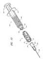
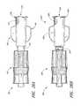
- FIG. 1Bshows a perspective view of the connector of FIG. 1A in a stretched, substantially opened configuration.
- FIG. 1Cshows a perspective view of an embodiment of the connector of FIG. 1A being connected to an exemplary female connector attached to tubing inserted into a patient.
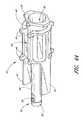
- FIG. 2shows a perspective view of an embodiment of a closeable male luer connector.
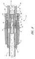
- FIG. 3shows a perspective view of a housing portion of the connector of FIG. 2 .
- FIG. 4Ashows a perspective view of a valve member portion of the connector of FIG. 2 .
- FIG. 4Bshows a perspective view of another embodiment of a valve member portion of the connector of FIG. 2 .
- FIG. 4Cshows a cross-sectional view of the embodiment of the valve member portion of the connector of FIG. 4B .
- FIG. 5shows a perspective view of a resilient member of the connector of FIG. 2 .
- FIG. 6shows a perspective view of a sealing portion of the connector of FIG. 2 .
- the relative size of the sealing portionis increased in comparison with the components of the connector shown in other figures to facilitate viewing.
- FIG. 7shows a perspective view of certain components of the connector of FIG. 2 in a partially assembled configuration.
- the housing portion of FIG. 5is not shown in FIG. 7 .
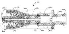
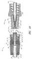
- FIG. 8shows a cross-sectional view of the connector of FIG. 2 adjacent a female portion of another medical implement. At this stage, fluid is impeded through the connector of FIG. 2 .
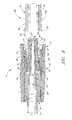
- FIG. 9shows a cross-sectional view of the connector of FIG. 2 in engagement with the medical implement of FIG. 8 . Fluid is flowing through the engaged connectors.
- FIG. 10shows a cross-sectional view of the connector of FIG. 2 adjacent another medical implement with a closeable female luer connector. At this stage, fluid is impeded through the connector of FIG. 2 and the female luer connector.
- FIG. 11shows a cross-sectional view of the connectors of FIG. 10 after engagement. Fluid is flowing through the engaged connectors.
- FIG. 12shows a perspective of the connector of FIG. 2 adjacent a syringe with a male luer tip. At this stage, fluid is impeded through the connector.
- FIG. 13shows a perspective view of the components of FIG. 12 after engagement. At this stage, fluid is still impeded through the connector.
- FIG. 14shows a cross-sectional view of the connector and the male luer tip of the syringe of FIG. 13 .
- FIG. 15shows a perspective view of the a closeable male luer connector located with its first end adjacent a syringe with a male luer tip and with its second end located adjacent a hypodermic needle with a female luer attachment portion.
- FIG. 16shows a perspective view of the components of FIG. 15 in engagement. At this stage, fluid can flow through the connector.
- FIG. 17is a cross-sectional view of the connector, male luer tip of the syringe, and hypodermic needle of FIG. 16 . At this stage, fluid can flow through the connector.
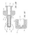
- FIG. 18Ais a perspective view of another embodiment of a closeable male luer connector.
- FIG. 18Bis a cross-sectional view of the connector of FIG. 18A .
- FIG. 18Cis a detail of the cross-sectional view of the connector of FIG. 18A .
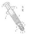
- FIG. 19is a perspective view of the connector of FIG. 18A located adjacent a syringe with a male luer tip.
- FIG. 20is a perspective view of the components of FIG. 19 in engagement.
- FIG. 21is a perspective view of another embodiment of a closeable male luer connector engaged with a syringe with a male luer tip.
- FIG. 22Ais a cross-sectional view of another embodiment of a closeable male luer connector.
- FIG. 22Bis a detail of the cross-sectional view of the connector of FIG. 22A .
- FIG. 23Ais a side view of another embodiment of a closeable male luer connector with a shroud.
- FIG. 23Bis a cross-sectional view of the connector of FIG. 23A .
- FIG. 23Cis a perspective view an embodiment of a closeable male luer connector adjacent a closeable female connector. At this stage, fluid flow is impeded through the female luer connector.
- FIG. 23Dis a perspective view of the components of FIG. 23C in engagement.
- FIG. 24Ais a perspective view of another embodiment of a closeable male luer connector.
- FIG. 24Bis a cross-sectional view of the connector of FIG. 24A .
- FIG. 25Ais a side view of another embodiment of a closeable male luer connector with a shroud.
- FIG. 25Bis a cross-sectional view of the connector of FIG. 25A .
- FIG. 26Ais a perspective view of another embodiment of a closeable male luer with a flexibly connected female luer connector.
- FIG. 26Bis a perspective view of another embodiment of a closeable male luer with a flexibly connected female luer connector.
- FIG. 27is a perspective view of another embodiment of a closeable male luer connector.
- FIG. 28is a cross-sectional view of the connector of FIG. 27 .
- FIG. 29is another cross-sectional view of the connector of FIG. 27 .
- FIG. 30is a cross-sectional view of the connector of FIG. 27 engaged with a syringe with a male luer tip. At this stage, fluid flow is impeded through the male luer connector.
- FIG. 31is a cross-sectional view of the connector and syringe of FIG. 30 engaged with a tube having a female luer attachment portion. At this stage, fluid flow is permitted through this assembly.
- FIG. 32is another cross-sectional view of the connector, syringe, and tube of FIG. 31 . At this stage, the connector is in the process of closing.
- FIG. 33is a perspective view of the connector of FIG. 27 prior to engagement with an embodiment of a priming cap.
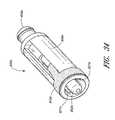
- FIG. 34is a perspective view of another embodiment of a closeable male luer connector.
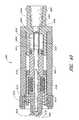
- FIG. 35is a cross-sectional view of the connector of FIG. 34 .
- FIG. 36is a perspective view of another embodiment of a closeable male luer connector.
- FIG. 37is a cross-sectional view of the connector of FIG. 36 .
- FIG. 38is a cross-sectional view of another embodiment of a closeable male luer connector.
- FIG. 39is a cross-sectional view of the connector of FIG. 38 engaged with a syringe with a male luer tip. At this stage, fluid flow is impeded through the male luer connector.
- FIG. 39Ais a cross-sectional view of the connector and syringe of FIG. 39 engaged with a tube having a female luer attachment portion. At this stage, fluid flow is permitted through this assembly.
- FIG. 40is a cross-sectional view of another embodiment of a closeable male luer connector.
- FIG. 41is a cross-sectional view of another embodiment of a closeable male luer connector.
- a variety of meansare shown for closing the second end of a male luer connector.
- these closing mechanismsfunction to prevent and/or impede fluid from escaping from or entering into the male luer, while allowing fluid flow when the male luer is manually opened or engaged with a corresponding female luer.
- terms such as “closed” or “sealed”should be understood as obstructions or barriers to fluid flow. These terms should not be understood to require that a particular structure or configuration achieves a complete fluid closure in all circumstances.
- FIG. 1Aan embodiment of a closable male luer connector 10 is shown in a closed position.
- the luer connector 10is attached to a gravity-fed IV bag 9 filled with fluid hanging from a pole stand 11 .
- a section of tubing 13is attached at the bottom of the bag 9 .
- the opposite end of the tubing 13is connected to the first end 12 of the luer connector 10 .
- a closing mechanism on the interior of the second end 14 of the luer connector 10prevents the fluid contained within the bag 9 from flowing through the tubing 13 and leaking out of the luer connector 10 , as long as the luer connector 10 remains in a closed configuration.
- FIG. 1Bthe connector 10 is illustrated in an open position. Fluid can flow out into the first end 12 of the connector 10 and out of the second end 14 of the connector 10 .
- a health care providercan move the male luer connector 10 into this configuration by grasping the second end of the closable male luer 10 with two fingers, grasping the tubing 13 with two other fingers, and gently moving the fingers in opposite directions.
- the IV delivery system illustrated in FIGS. 1A and 1Bcan be easily readied for fluid communication with a patient.
- the tubing 13is filled with air when it is initially connected to the IV bag 9 . If the other end of the tubing 13 is connected to a closed connector, as illustrated in FIG. 1A , the air cannot escape and fluid cannot enter the tubing 13 from the IV bag 9 .
- the luer connector 10is therefore manually moved into the opened position until all of the air has been purged through the luer 10 and the fluid in the IV bag 9 fills the tubing 13 and connector 10 .
- a catheter 17has been inserted into a patient's arm 15 .
- the catheter 17penetrates the skin of the arm 15 and is preferably fluidly connected with the patient's bloodstream.
- the catheter 17is also connected to a length of medical tubing 19 attached to a female medical connector 21 .
- the example of a female medical connector 21 illustrated in FIG. 1Cis a version of the Clave.TM. connector manufactured by ICU Medical, Inc., San Clemente, Calif.
- Various embodiments of a connector of this typeare illustrated and described in U.S. Pat. No. 5,685,866, which is incorporated herein by reference in its entirety. It is contemplated that many of the male luer embodiments disclosed herein can be used with other types of female connectors.
- the tubing 19 , catheter 17 , and female connector 21were previously primed with fluid using standard procedures.
- the luer connector 10is primed as described previously and brought into engagement with the female connector 21 .
- fluidis permitted to flow from the IV bag 9 into the patient.
- the male connector 10 and female connector 21are disengaged, fluid is once again prevented from flowing out of the second end 14 of the male connector 10 .
- fluidis also prevented from flowing out of the opening in the female connector 21 .
- FIGS. 1A-1CThe embodiment illustrated in FIGS. 1A-1C is described in further detail below.
- Each of the other embodiments disclosed hereincan be used in the illustrated fluid system, and in various modifications and alternatives thereof.
- the various embodiments of connectors in accordance with the inventionscan be used in a wide variety of additional medical fluid systems.
- the disclosed connectorscan also be used to transfer bodily fluids such as blood, urine, or insulin, nourishing fluids, and/or therapeutic fluids such as fluids used in chemotherapy treatments.
- the disclosed connectorscan also be used to interconnect various other components of fluid transfer systems.
- the assembled luer connector 10comprises four portions: a housing 23 , a valve member 16 , a resilient member 18 , and a sealing ring 20 (not visible in FIG. 2 ). These portions are individually illustrated in FIGS. 3 through 6 , and will be discussed in further detail with reference to these figures.
- the luer connector 10can be constructed of more or fewer portions, and such portions can be combined into different configurations.
- FIG. 3illustrates the housing 23 of the connector 10 , apart from the other portions of the luer connector 10 .
- the housing 23is generally a tube-like structure with an axial passageway 28 that extends from the first end 12 of the connector 10 through the upper housing 34 , and the middle portion 32 , and the luer tip 22 , to the second end 14 of the housing 23 .
- the length of the housing 23 from the first end 12 to the luer tip 22is approximately 11 ⁇ 8 inches.
- the housing 23is preferably, but not necessarily, less than or equal to about 11 ⁇ 2 inches from the first end 12 to the second end 14 so that the weight and bulk of the connector are minimized.
- the housing 23can have any suitable length for a particular application.
- the luer tip 22connects to the remainder of the housing 23 at a base 25 that is surrounded by a shroud 24 .
- the end 27 of the luer tip 22 towards the second end of the luer connector 10extends some distance beyond the edge 29 of the shroud.
- the shroud 24preferably has inner threads 26 on an interior wall that help securely attached the connector 10 in a removable fashion to another medical implement.
- the shroud 24can include other structures or materials for providing a releasable connection, including quick-release mechanisms and other means.
- the shroud 24includes a plurality of depressions 31 on an outer surface to assist the user in firmly grasping and twisting the shroud 24 of the housing 23 with the fingers.
- the depressions 31have upwardly tapering sidewalls 33 that prevent the fingers from sliding off the connector 10 .
- the surface of the housing 23is approximately co-planar with the surface of the depression 31 , while on an end towards the second end 14 of the connector 12 of each depression 31 , the surface of the housing 23 is offset from, and preferably lies above, the surface of the depression 31 .
- This configurationallows the fingers to comfortably slide in a direction towards the second end 14 of the connector 10 along the housing 23 into a position for gripping or twisting the connector 10 .
- a tapered wall 33 on an end towards the second end 14 of the connector 10 of the depression 31resists further movement by the fingers in the direction of the second end 14 .
- a series of depressions 31extend around substantially the entire outer surface of the shroud so that the user's fingers, when positioned on opposite sides of the connector 10 , will likely encounter a depression 31 regardless of the orientation of the connector 10 during use.
- the tip 22has a tapered external wall.
- the diameter of the tip 22becomes gradually smaller from the base 25 towards the second end 27 .
- the tip 22includes a hole at its second end 27 .
- an interior hole 35leads into a region of the fluid passageway 28 in the middle portion 32 of the luer connector 10 .
- the dimensions of the luer tipcan be made to comply with applicable standards and/or regulations, such as the ANSI standards.
- the interior wall of the luer tip 22preferably includes a shelf 30 that extends radially inwardly toward the axis of the fluid passageway 28 surrounded by the luer tip 22 , making the fluid passageway 28 narrower at its second end 27 than in the region adjacent to the second end 27 .
- the surface of the shelf 29 that faces radially inwardly toward the central axis of the connector 10is tapered in a manner similar to the taper of the outer surface of the tip 22 (see FIGS. 8 and 9 ).
- the inner diameter of the shelf 29narrows in a direction from the side towards the first end to the side of the shelf 29 towards the second end.
- the shelf 29 in the luer tip 22helps to block and/or impede fluid flow through the connector 10 when the second end of the valve member 16 abuts against it.
- the middle portion 32 of the housing 23lies between the shroud 24 and the upper housing 34 . As illustrated, the middle portion 32 has a smaller outer diameter than either the shroud 24 or upper housing 34 .
- the middle portion 32also has two generally rectangular openings 36 disposed on opposite sides of the housing 23 from each other. When the connector 10 is assembled, the middle portion 32 is generally covered by a portion of the resilient member 18 (see, e.g., FIG. 2 ). As a result, the middle portion 32 does not generally come into contact with the fingers during use. Thus, in some embodiments, a grippable surface need not be used for the middle portion 32 .
- the middle portion 32can therefore have a smaller diameter and smoother surface than either of the other sections of the housing 23 .
- the upper housing 34is generally split into two wall sections 45 a , 45 b by two gaps 38 (only one shown in FIG. 3 ).
- the upper housing 34includes a series of depressions 37 similar in shape and function to the depressions 31 on the shroud 24 .
- the upper housing 34may also comprise one or more protrusions 43 that extend into the gaps 38 . In the assembled configuration, the protrusions 43 help to retain a portion of the resilient member 18 between the gaps 38 in the wall sections 45 a , 45 b (see FIG. 2 ).
- the protrusions 43are tapered from a smaller thickness on their ends towards the first end of the connector to a larger thickness on their ends towards the second end of the connector.
- the tapering of the protrusions 43helps in the insertion and retention of the portion of the resilient member 18 in a desired position and orientation, while allowing for bending and contortion of the resilient member 18 during use.
- the protrusions 43also help prevent the valve member 16 from advancing too far in the direction of the first end as the connector 12 is moved into the opened position by contacting the set of protrusions 44 toward the second end of the valve member 16 .
- the tapering of the protrusions 43allows the protrusions 44 of the valve member 16 to be advanced towards the second end during assembly into the housing 23 past the protrusions 43 of the housing 23 .
- the corners 47 towards the first end of the connector on each of the wall sectionsare preferably rounded to prevent snagging, scratching, or other damage or irritation to the fingers or resilient member 18 during use.
- the exterior surface of the upper housing 34includes a lower shelf 39 and the exterior surface of the shroud 24 includes a shelf 41 configured to help retain a central portion of the resilient member 18 around the housing 23 in the assembled configuration (see FIG. 2 ).
- the shelf 39 of the upper housing 34is preferably substantially horizontal to discourage any sliding of the resilient member 18 in the direction of the first end of the connector.
- the shelf 41 of the shroud 24is preferably tapered (see FIG. 8 ) to assist in the proper positioning of the resilient member 18 on the housing 23 during manufacturing of the connector 10 .
- the housing 23can be constructed from any of a number of different materials.
- the housing 23can be constructed from a relatively rigid material, such as polycarbonate or other polymeric material.
- the housing 23 and/or valve member 16 of this embodiment, or components of other embodiments,can also be constructed of a hydrophobic material, such as Bayer Makrolon, or any other suitable material.
- the valve member 16 of the male luer 10is illustrated apart from the other components of the connector 10 .
- the valve member 16comprises a fluid passageway 52 of varying diameter extending from the first end 48 of the valve member 16 to the second end 56 thereof, surrounded by additional structures.
- the valve member 16 and corresponding section of the fluid passageway 52are relatively wide to accommodate a section of standard-diameter medical tubing inserted therein.
- a tube 40 surrounding a portion of the fluid passageway 52is attached to the portion near the first end of the valve member 16 .
- the tubeis adjacent to two approximately parallel struts 42 along at least a portion of the tube 40 .
- the tube 40can have a circular cross-section or other appropriate cross-section.
- the struts 42are preferably relatively thin and approximately planar. A first end of each strut 42 connects to the valve member 16 at approximately the middle section of the valve member 16 , and a second end of each strut extends toward the second end 56 of the valve member 16 . The second end 56 of the valve member 16 preferably extends further than the ends of the struts. There is preferably an open space between the inner wall of each strut 42 and the outer wall of the tube 40 .
- the fluid passageway 52comprises a wider region with protrusions 44 along its external surface.
- Protrusions 44form two channels 46 (only one is shown in FIG. 4A ) lengthwise along opposing sides of the body of the valve member 16 .
- the struts 42are spaced circumferentially from the channels 46 , as illustrated.
- a circumferential channel 48may be formed around the perimeter of the body of the valve member 16 .
- Raised tabs 49can be formed along the edge of the channel 48 toward the first end of the connector, while the raised middle portion of the valve member 16 can form the edge of the channel 48 toward the second end of the connector.
- the raised tabs 49do not extend evenly about the perimeter of the first end of the valve member 16 , but instead have two larger sections that are spaced diametrically from each other.
- the amount of material necessary to construct the valve member 16can be reduced by indentations made in the outer layers of this portion.
- the tube 40can have a passage 50 disposed therethrough. This passage 50 preferably extends from a hole 52 at the first end of the valve member 16 to a pair of holes 50 (only one shown in FIG. 4A ) positioned substantially adjacent to the second end of the valve member 16 . In the illustrated embodiment, these holes 52 are generally rectangular in shape.
- the region of the tube 40 near the second end of the connectorcan also be formed with only one hole or more than two holes, and other shapes for one or more of the holes can also be employed.
- the holes 52can be formed with a tear-drop shape (e.g., narrow on one end and wider on an opposite end), which facilitates an injection molding process of manufacture.
- the valve member 16can be constructed without a fluid path and function as a blocking plunger for fluid flowing around the valve member 16 rather than a means for conveying fluid between the first and second ends of the connector 10 .
- the tube 40 of the valve member 16comprises, at its second end, a flange section 58 .
- the flange section 58preferably extends further in the radial direction than the adjacent portion of the tube 40 .
- the flange section 58can be formed of the same or substantially the same material as the rest of the tube 40 .
- the flange section 58preferably tapers from the first end of the valve member 16 towards the second end of the tube 40 .
- the taperis formed at a 5-degree angle, and has a substantially identical taper to that of the radially inwardly facing surface of the shelf 30 of the housing 23 . Other amounts of taper, or no taper, can also be used.
- the valve member 16may be constructed from a number of different materials. Examples of such materials include polycarbonate or other polymeric materials.
- the valve member 16can be approximately the same length or somewhat shorter than the housing 23 .
- the length of the valve member 16can be approximately 1 inch.
- the valve member 16can be substantially shorter than the length of the housing 23 .
- the valve member 16can be formed from the same rigid materials as the housing 23 . In certain applications, for example, semi-rigid or even more flexible materials may be desirable for use in the valve member 16 , and more particularly for the flange section 58 toward the second end of the tube 40 .
- the valve member 16can be manufactured through injection molding.
- at least two gatesare used to facilitate distribution of molten plastic throughout the mold.
- one gatecan be located along one of the sides of the valve member 16 between the end of the struts 42 towards the first end of the connector and the raised tabs 49 and another can preferably be located near the holes 52 in the valve member 16 .
- the locations of the gatesare not fixed, however, and other locations on the valve member 16 can be used for gates when injection molding the valve member 16 . Constructing both the housing 23 and the valve member 16 of this or other embodiments out of the same material lessens the chance of deteriorated performance of the connector 10 due to thermal expansion/contraction or chemical interaction between the connector 10 and its environment.
- valve member 16 of the illustrated embodimentis configured as shown in FIG. 4A , many other configurations are possible.
- the valve member 16can be relatively smooth on its external surface, and can principally comprise the tube 40 defining the passage 50 .
- different numbers of struts 42can be disposed along the sides of the valve member 16 .
- the raised tabs 150 near the first end of the valve member 16can also comprise an external engaging surface 150 , such as a screw thread, for removably attaching a medical implement (not shown), such as a syringe, with the first end of the valve member 16 .
- the channel 48additionally can be tapered along the internal surface 182 .
- the taper of the channel 48can result in a decrease in width of the channel with a larger size at the first end 180 of the valve member 16 and a smaller size towards the second end 184 of the valve member.
- the internal taper of the channel 48can compliment and closely fit with the taper of a male luer. Such an internal taper can conform to ANSI standards and/or regulations, such as the standard for medical syringes.
- the tube 40 of the valve member 16does not have a flange section 58 that extends radially outwardly beyond the wall of the tube 40 , as in the embodiment of FIG. 4A .
- the wall of the tube 40tapers radially inwardly in the region of the second end.
- the second end 27 a of the luer tip 22 acan have a smaller cross-sectional second portion 170 which decreases the likelihood of fluid escaping along the internal surface of the second end 27 a of the luer tip 22 a .
- a larger cross-sectional region 160can transition to the smaller cross-sectional portion 170 towards the second end of the connector in many different ways, such as with an abrupt stair-step transition as illustrated in FIG. 4C or with a gradual tapering transition, or other transitions.
- Some sample cross-sectional diameters of the opening at the second end 27 a of the luer 22 ainclude those of about 2 mm or less, including about 0.5 mm, 0.75 mm, 1.0 mm, 1.25 mm, 1.5 mm, and 1.75 mm.
- the diameters of the opening in the second end 27 acan also be in the ranges of 0.4 mm-1.8 mm, 0.5 mm-1.5 mm, and 0.5-1.0 mm. Other diameters, either inside or outside the listed ranges can also be used.
- the second end of the valve member 16can be sized appropriately to occupy the space in the opening of the second end 27 a of the luer 22 a.
- the closeable male luer connector 10has both a female end 180 and a male luer end 184 .
- the closeable female connector 21 of FIG. 1C (referenced above) and 210 of FIGS. 10 and 11 (described in more detail below), as well as other standard female connectors with similar external structure,also have both female and male ends.
- such female connectorsutilize seals or other fluid barriers to impede the flow of fluid on the female end but not on the male end.
- the female end of any of the closeable male luer connectors disclosed hereincan be configured to include a closeable female end.
- the structure for selective fluid-impedence with the female connector 21 or 210 , or any of the other standard female connectorscould be included within the female end of any of the closeable male luer connectors disclosed herein to provide a connector that selectively seals or impedes fluid flow on both ends.
- a resilient seal elementit can be advantageous for a resilient seal element to be positioned at or near the female opening, as shown in U.S. Pat. No. 5,685,866.
- seal elementBy positioning the seal element in this manner, it is possible to cleanse the female opening prior to use with antiseptic with a wiping motion to avoid a harmful accumulation of debris, bacteria, antiseptic, or other unwanted substances on the seal element and/or in the region between the seal element and the housing of the connector adjacent to the seal element.
- the resilient member 18is formed from two rings 60 , 62 separated by two elastic members 64 .
- the rings 60 , 62 and/or the elastic members 64can be made of a deformable material configured to exert a restoring force when stretched.
- the elastic members 64function to restore the rings 60 , 62 to their unextended configuration.
- the elastic members 64can be constructed from a number of elastic materials. In some embodiments, the elastic members 64 are made from a silicon rubber elastic material. In other embodiments, the elastic members 64 can be made from a shape-memory material. In still other embodiments, the elastic members 64 and/or the resilient member 18 can comprise springs or other structures capable of exerting a restoring force.
- the rings 60 , 62can also be constructed from a number of materials.
- the rings 60 , 62are constructed from the same deformable elastic material that comprises the elastic members 64 .
- the rings 60 , 62can be stretched into a diameter to extend around the appropriate portion of the housing 23 to which each respective ring 60 , 62 is attached.
- the resilience of the rings 60 , 62can function to effectively hold each ring 60 , 62 in place on the housing 23 .
- the rings 60 , 62can be constructed from rigid or semi-rigid materials, and can, for example, comprise half-circles that can be snapped into and out of position.
- the resilient member 18can be integrated into the valve member 16 or housing 23 .
- other structures and/or configurationscan be used to selectively urge the valve member 16 and the housing 23 together in a different manner than a resilient member 18 .
- the sealing portion 20is substantially cylindrical and has a bore 66 extending therethrough.
- the sealing portion 20further comprises a pair of generally rectangular protrusions 68 extending from the sidewalls of the cylindrical portion at diametrically opposed positions.
- the protrusions 68can have different shapes and/or positions.
- the sealing portion 20can also have a generally smaller-diameter middle portion 67 surrounded by two rings 69 at either end with larger diameters.
- the sealing portion 20can be constructed from a number of different materials.
- the sealing portion 20is made from a silicon-based deformable material 70 .
- Silicon-based deformable materialsare among those that form fluid-tight closures with plastics and other rigid polymeric materials.
- the sealing portion 20can be made from the same material as the resilient member 18 .
- FIG. 7certain components of the male luer 10 of an embodiment are shown. As illustrated, the housing 23 is omitted. The valve member 16 , the resilient member 18 , and the sealing portion 20 are shown in their respective assembled locations.
- the smaller ring 62 of the resilient member 18fits within the circumferential channel 54 of the valve member 16 .
- the smaller ring 62can be stretched until it has a larger inner diameter than the raised tabs 49 at the first end of the valve member 16 . Once the small ring 62 has been advanced into position about the circular channel 54 , it can be released, so that it wraps tightly about the circular channel 54 , as shown.
- the larger ring 60 of the resilient member 18extends around the middle portion 32 of the housing 23 (as shown in FIG. 2 ), and can be stretched and positioned in a manner similar to that described above with respect to the small ring 62 .
- the elastic members 64 of the resilient member 18can then extend between the small ring 62 and the larger ring 60 of the resilient member 18 and preferably extend along and within the channels 46 in the valve member 16 . Once located within these channels, the elastic members 64 are, in effect, trapped by the protrusions 44 along the channel outer walls. As seen in FIG. 2 , the elastic members 64 can also extend along the gaps 38 in the upper housing 34 of the housing 23 . The gaps 38 are generally located above the channels 46 in the illustrated embodiment.
- the resilient member 18thereby provides an elastic connection between the housing 23 and valve member 16 , pulling the valve member 16 into engagement with the housing 23 .
- the sealing portion 20which is partially hidden by the resilient member 18 in FIG. 7 , preferably fits snugly around the tube 40 and lies in between the struts 42 of the valve member 16 .
- FIG. 8illustrates a cross-section of the male luer of the present embodiment adjacent an exemplary female connector 92 .
- the valve member 16is configured to be positioned within the housing 23 .
- the tube 40 of the valve member 16can be inserted into and through the lumen 28 .
- the struts 42are configured to pass through corresponding slots that extend lengthwise through the middle portion 32 of the housing 23 .
- the struts 42are adjacent to the tip 22 along two sides, and the tube 40 is at least partially contained within the tip 22 .
- the protrusions 44are captured within the gaps 38 formed in the upper housing 34 of the housing 23 .
- a closing mechanism 56is adapted to close the fluid passage extending through the closable male luer 10 from fluid communication with the external environment, preferably whenever the male luer 10 is not engaged with the female connector 92 .
- the fluid passageway 52comprises the lumen 28 as well as the passage 54 of the valve member 16 .
- the closing mechanism 56 of the illustrated embodimentcomprises both the flange section 58 of the tube 40 and the internal taper of the raised portion 29 of the lumen 28 . As these two surfaces contact, they can form a closure at or near the second end 20 of the male luer 10 .
- the substantially matched internal tapering surfaces of the raised portion 58 of the tube 40 and the raised portion 29 of the lumen 28assist in providing closure of the female connector 92 .
- a relatively fluid-tight closureis formed.
- the engagement between the raised portions 29 and 58can also be created in a number of other ways.
- the material of the flange section 58 and the material of the raised portion 29 of the lumen 28are configured to fit closely together, and are made of sufficiently compatible materials, to form a fluid-tight closure.
- the flange section 58 , and/or additional portions of the valve member 16can be constructed from a deformable material that more closely follows the contours of the internal surface of the lumen 28 , and the lumen 28 need not have a taper.
- the sealing portion 20is configured, in some embodiments, to prevent fluid from escaping from within the male luer connector 10 .
- the sealing portion 20sits between the middle portion 32 of the housing 23 and the tube 40 .
- the sealing portion 20When fluid flows within the lumen 28 of the housing 23 and along the outer surface of the tube 40 , the fluid is prevented from flowing past the middle portion 32 by the sealing portion 20 , and more particularly by the rings 69 at either end of the sealing portion 20 .
- the sealing portion 20is preferably held in position between the housing 23 and valve member 16 by the protrusions 68 (see FIG. 6 ) configured to fit within the holes 36 in the middle portion 32 of the housing 23 .
- the protrusions 68help to maintain the sealing portion 20 in proper alignment.
- the female connector 92can comprise an elongate body 72 having a fluid passageway 74 therethrough, and the female connector 92 can have a tip 76 near its distal end.
- the tip 76 of the female connector 92has a radially extending surface 78 disposed on its external surface.
- the female connector 92can have a fluid conduit positioned within the female connector 92 .
- the fluid conduitis not included or required in all female connectors compatible with the connectors 10 disclosed herein.
- the fluid passageway 74is preferably tapered such that the diameter of the fluid passageway 74 decreases in the distal direction.
- the housing 23 , the valve member 16 , the resilient member 18 , and the sealing portion 20are in an assembled configuration, in which the closing mechanism 56 forms a closing engagement between the flange section 58 and the interior of the lumen 28 .
- the sealing portion 20is in closing engagement between the valve member 16 and the housing 23 . Fluid from the passage 50 can flow through the windows 54 of the tube 40 of the valve member 16 . In this position, the windows 54 communicate with the interior of the tip 22 , but not yet with the external environment.
- the lumen 28is closed at its second end by the closing mechanism 56 and at its first end by the sealing portion 20 .
- the struts 42 of the valve member 16extend through slots in the housing 23 such that their ends extend to positions near the end of the shroud 24 toward the second end of the connector. These struts 42 are configured to engage the proximal ends 84 of the female connector 92 as the female connector 92 advances into engagement with the closable male luer 10 .
- FIG. 8the male and female luers are shown in an unengaged configuration.
- the radially extending surface 78 of the female connector 92are screwed into the inner threads 26 of the male luer 10 .
- the two luerscan be threadedly engaged towards one another until the taper of the inner surface 80 of the female connector 92 lies adjacent the correspondingly tapered external surface of the tip 22 .
- the two luerscan be threadedly engaged until the second end of the tip 22 forms a closure with a corresponding surface (not shown) of the female connector 92 .
- the proximal end 84 of the tip of the female connector 92contacts the struts 42 of the valve member 16 .
- the struts 42are moved in the direction of the first end of the male connector by the female connector 92 , displacing the valve member 16 relative to the housing 23 .
- the flange section 58moves from the second end of the tip 22 of the housing 23 towards the first end of the male connector.
- a spaceforms between the valve member 16 and the housing 23 and fluid is allowed to pass through the hole 30 into the fluid passageway 74 of the female connector 92 , or vice versa.
- an internal fluid conduitcontacts the second end of the valve member 16 before the housing of the female connector 92 contacts the struts 42 to open the male connector 10 .
- the closureremains intact until the inner surface 80 of the tip of the female connector 92 has formed a closing engagement with the outer surface of the tip 22 of the male luer 10 .
- the passage 50 of the male luer 10need not be in fluid communication with the external environment.
- the elastic members 64(not shown in FIG. 9 ) of the resilient member 18 distend and exert a restoring force. As long as the female connector 92 engages the male luer 10 , this restoring force can be resisted by the radially extending surface 78 of the female connector 92 contacting the inner threads 26 of the housing 23 . However, when the female connector 92 is withdrawn from the male luer 10 , the resilient member 18 returns the valve element of the valve member 16 to closing engagement with the lumen 28 .
- the sealing portion 20preferably maintains a fluid barrier between the outer surface of the tube 40 and the inner surface of the lumen 28 .
- the position of the sealing portion 20is maintained by the protrusions 68 .
- the sealing portion 20can be positioned by gluing the outer surface of the deformable material 70 to the inner surface of the lumen 28 of the housing 23 . Other means of fixing the sealing portion 20 can also be used.
- the fluid passageway 74 of the female connector 92can fluidly communicate with the passage 50 of the valve member 16 .
- Fluidcan thereby flow from tubing 13 attached to the male luer 10 , into the passage 50 of the valve member 16 , through the windows 54 into the lumen 28 , out from the lumen 28 through the hole 30 at the second end of the tip 22 into the fluid passageway 74 of the female connector 92 , and vice versa.
- Fluidis prevented from escaping the male luer 10 through the gap between the housing 23 and valve member 16 by the sealing portion 20 .
- a fluid-tight closurecan also be formed between corresponding tapers of the tip 22 of the housing 23 and the inner surface 80 of the female connector 92 .
- the connector 10is displayed adjacent to a closeable female luer connector 210 .
- the closeable female luer connector 210comprises an outer housing 213 , a void space 212 , a fluid passageway 218 , a fluid conduit 216 with one or more holes 215 , a compressible seal element 214 with a proximal surface 217 , and a threaded engagement region 211 .
- the closeable female connector 210is positioned with its proximal end adjacent the second end 56 of the male connector 10 .
- the threaded engagement region 211 of the closeable female connector 210can conform to standard sizing for luer connectors, such as those that meet ANSI standards.
- the compressible seal element 214can be composed of water-impermeable, resilient material which can reduce in size when a force is exerted upon it.
- the fluid conduit 216can be composed of a rigid material, such as polycarbonate plastic, which is capable of resisting deformation when a force sufficient to compress the seal element 214 is exerted upon the closeable female connector 210 .
- the fluid passageway 218can place the fluid conduit 216 in fluid communication with the second end 219 of the closeable female connector 210 .
- At least one hole 215 in the fluid conduit 216can be sealed by the compressible seal element 214 to prevent the fluid passageway 218 from being in fluid communication with the void space 212 between the compressible seal element 214 and the inner wall of the housing 213 and/or with the exterior of the housing 213 .
- the hole or holes 215can be sized appropriately small enough to permit fluid to pass between the fluid passageway 218 and the void space 212 at an appropriate flow rate.
- One such size for the hole or holes 215is approximately one millimeter in diameter, although irregular shapes and other sizes can be used. Holes of at least about 1 mm or approximately 1 mm-3 mm, or less than about 1 mm can also be used.
- the connector 10can be engaged with a tubing 13 containing a fluid.
- the connector 10can be threadedly engaged with the closeable female connector 210 .
- the threaded region 211 of the closeable female connector 210can engage with the inner threads 26 of the male connector 10 to engage the connectors 10 , 210 , as illustrated.
- the luer tip 22advances into the closeable female connector 210 by compressing the compressible seal element 214 .
- the luer tip 22contacts the compressible seal element 214 on the proximal surface 217 of the compressible seal element 214 .
- the force exerted to engage the connectors 10 , 210 and engage the threaded regions 26 , 211is sufficient to compress the seal element 214 to expose the holes 215 in the fluid conduit 216 .
- the seal element 214 compressedthe fluid passageway 218 is in fluid communication with the interior space of the luer tip 22 .
- the fluid conduit 216contacts the end of the valve member 16 towards the second end of the male connector.
- the valve member 16is displaced towards the first end of the male connector by the contact and continued advancement of the luer tip 22 .
- the resilient member 18exerts a closing force in a direction towards the second end of the male connector on the valve member 16 .
- the tip of the valve member 16 towards the second end of the male connectorgenerally maintains contact with the fluid conduit 216 throughout the engagement.
- the flange section 58 of the valve member 16separates from the interior surface of the housing 23 through which the hole 30 passes.
- the windows 54are opened to fluid communication with the closeable female connector 210 .
- the compressed seal element 214inhibits fluid flow into the interior of the closeable female connector 210 beyond the luer tip 22 .
- fluidcan flow from the tubing 13 at the end of the valve member 16 toward the second end of the male connector and into the tube 40 through the windows 54 into the interior of the lumen 28 , out the hole 30 in the luer tip 22 , into the interior of the outer housing 213 of the closeable female connector 210 , in the holes 215 of the fluid conduit 216 and into the fluid channel 217 in the interior of the fluid conduit 216 .
- the second end of the connector 210is placed in fluid communication with the proximal end 219 of the closeable female connector 210 .
- the sealing portion 20preferably maintains a fluid barrier between the outer surface of the tube 40 and the inner surface of the lumen 28 , confining the flow of fluid towards the closeable female connector 210 .
- the connectors 10 , 210can be threadedly disengaged.
- the force exerted by the resilient member 18can return the connector 10 to its pre-engaged state by directing the valve member 16 to engage the flange section 58 of the end of the valve member 16 toward the second end of the male connector with the internal surface of the luer tip 22 .
- the resilient material of which the compressible seal is composedcan return to its shape in the closed position and the proximal surface 217 can seal the proximal tip of the closeable female connector 210 .
- the connector 10can be engaged with a syringe 250 .
- the syringe 250 and connector 10are displayed adjacent to each other.
- the syringecan comprise a male luer connector 252 , a plunger 258 , a reservoir 260 , and convenient finger anchors 262 .
- the luer connector 252can further comprise an internally threaded shroud 254 and a syringe luer tip 256 .
- a threaded surface 150is disposed on the outside surface of the first end of the valve member 16 .
- the connector 10can be threadedly engaged with the syringe 250 .
- the shroud 254can engage with the end 16 of the valve member toward the first end of the connector to connect the connector 10 to the syringe 250 .
- the reservoir 260 of the syringe 250can be placed in fluid communication with the tube 40 interior to the valve member 16 .
- FIG. 14the engagement illustrated in FIG. 13 is shown in a cross-sectional view.
- the syringe 250is threadedly engaged with the connector 10 by the engagement between the shroud 254 and the threaded surface 150 of the valve member 16 .
- the luer tip 252 of the syringe 250is extended into the tube 40 of the valve member 16 .
- the reservoir 260 of the syringeshown here with a fluid in the reservoir 260 , is in fluid communication with the interior of the valve member 16 .
- the fluidcan pass through the tube 40 and towards the luer tip 22 of the connector 10 .
- the fluidcannot exit the connector 10 out its male luer tip 22 because the flange section 58 is in contact with the interior surface of the lumen 28 . Accordingly, the hole 30 in the tip of the housing 23 towards the second end of the connector is blocked by the valve member 16 .
- the valve member 16may need to be temporarily opened to release air (as described in more detail below).
- the connector 10is shown adjacent to and between a syringe 250 and a hypodermic needle with sheath 270 .
- the syringe 250can comprise a male luer connector 252 , a plunger 258 , a reservoir 260 , and convenient finger anchors 262 .
- the luer connector 252can further comprise an internally threaded shroud 254 and a syringe luer tip 256 .
- the needle with sheath 270can comprise a housing 266 with raised tabs 264 on the engagement end and a needle 268 .
- the connector 10is shown threadedly engaged with both the syringe 250 and needle with sheath 270 .
- the threaded surface 150 of the valve member 16 of the connector 10can engage with the threaded shroud 154 of the syringe 250 .
- the luer tip 256can protrude into the tube 40 of the valve member 16 .
- the raised tabs 264can engage with the inner threads 26 of the shroud 24 of the connector 10 .
- the luer tip 22 of the connector 10can protrude into the housing 266 of the needle sheath.
- FIG. 17the engagement shown in FIG. 16 is illustrated in a cross-sectional view.
- the connector 10is engaged by a syringe 250 and a needle with a sheath 270 .
- the syringe 250is threadedly engaged with the threaded surface 150 of the valve member 16 of the connector 10 .
- the needle with sheath 270is threadedly engaged with the inner threads 26 of the shroud 24 .
- the luer tip 256 of the syringe 250protrudes into the tube 40 of the valve member 16 .
- the reservoir 260 of the syringe 250is in fluid communication with the tube 40 of the valve member 16 through the luer tip 256 .
- the connector 10is engaged with the needle with a sheath 270 .
- the housing 266 of the needle with sheath 270has raised tabs 264 near its proximal end.
- the raised tabs 264threadedly engage the inner threads 26 of the shroud 24 of the connector 10 .
- the proximal end of the housing 266can contact the struts 42 of the valve member 16 .
- the valve member 16has been displaced a distance which separates the flange section 58 from the tapered interior wall of the lumen 28 sufficiently to permit fluid to flow out the windows 54 of the valve portion 16 .
- the fluidcan then flow out the hole 30 in the end of the luer tip 22 and into the housing 266 of the needle with sheath 270 .
- the hollow needle 268permits the fluid to flow from within the housing 266 out the distal tip of the needle 268 .
- the sealing portion 20preferably maintains a fluid barrier between the outer surface of the tube 40 and the inner surface of the lumen 28 , confining the fluid in the lumen and the direction of flow toward the hole 30 in the luer tip 22 .
- the syringe 250is in fluid communication with the distal tip of the needle 268 . As was previously illustrated in FIGS.
- the connector 10will generally not permit fluid to flow out of the syringe 250 without a component engaged with the second end 14 of the connector 10 .
- the component illustrated in FIGS. 15-17is a needle with a sheath 270 ; however, other components, such as those which permit fluid flow and possess a female luer engagement portion, can also be used.
- FIG. 18Adisplays a perspective view of another embodiment of a closeable male luer.
- the rotatable connector 300is comprised of a housing 310 , an internal passageway 322 and a seal element 330 .
- the housingis further comprised of a luer tip 312 , a luer receiver 316 at the first end of the connector 300 , an engagement portion 318 , a manipulation portion 320 , and a raised portion 340 .
- the seal element 330can have an opening 350 along its face 314 in a transverse direction.
- the internal passageway 322can extend from the luer receiver 316 to the luer tip 312 .
- the housing 310can be composed of a water-impermeable material, such as a polycarbonate plastic.
- the housing 310can also be composed of a hydrophobic plastic.
- Other examples of materials suitable for construction of the housing 310are glassed-filled GE Valox 420 or polypropylene. Depending on the application
- the housing 310 illustratedis configured to receive a male luer tip at the luer receiver 316 by threadedly engaging the male luer at its engagement portion 318 .
- the receiver 316can conform to ANSI standards for a luer receiver.
- the illustrated manipulation portion 320has two tabs extending radially from the central axis of the housing 310 .
- the manipulation portion 320is configured to aid the user in grasping and rotating the connector 300 .
- the housing 310 illustratedis also constructed to provide a closeable male luer at its second end.
- the luer tip 312 at the second endcan be constructed to ANSI standards for a male luer tip.
- the luer tipjoins the main body of the housing 310 at the raised portion 340 .
- the raised portion 340is constructed to inhibit the luer tip 312 from advancing too far into a luer receiver.
- the housing 310can also have a recessed portion 342 behind the raised portion 340 .
- the luer tip 312can also have a seal element 330 which has a face 314 towards the second end of the connector.
- the seal element 330can be any water-impermeable, resilient material, including without limitation, silicone. The selection of the material for construction of the seal can be accomplished by one skilled in the art.
- the luer tip 312can taper smaller in a direction from the raised portion 340 as it approaches its second end.
- the seal element 330can also have an opening 350 in the face 314 toward the second end of the connector prior to engagement with any other component.
- the opening 350can be a slit in a transverse direction to the longitudinal axis of the housing 310 .
- the opening 350can be centered across the face 314 , or located in another position on the face 314 .
- the seal element 330can cover the entire second end of the luer tip 312 , or only a portion thereof.
- the seal element 330can be attached to the housing by an overmolding process, among other attachment methods.
- the housing 310can be formed by injection molding in a first step, and then in a second step, the housing 310 can be re-inserted into a mold (or remain in a mold) and an appropriately sized molding pin (not shown) can be inserted through a wider end of the housing 310 , such as the second end. Silicone material can then be injected into the mold to form the seal element 330 . In other embodiments, the seal element 330 can be glued or otherwise adhered into the housing 310 .
- the seal element 330can inhibit fluid from flowing through the housing 310 when the luer tip 312 is not engaged with another component.
- the connector 300can be used to control flow of fluid through its luer tip 312 .
- a fluid-containing componentsuch as a syringe
- fluidis permitted to fill the housing 310 of the connector 300 by flowing through the internal passageway 322 , but the seal element 330 can substantially inhibit flow of fluid out the luer tip 312 .
- the connector 300may need to be opened to allow the air or other gas to escape before the fluid can enter.
- the internal surface of the seal element 330can be adapted to increase the resistance against the widening of the opening 350 , which could allow fluid to escape when the fluid (not shown) exerts a pressure against the seal element 330 from the internal passageway 322 .
- the connector 300inhibits flow of fluid from a fluid-bearing component when the connector 300 is attached to the male luer of the fluid-bearing component without another component connected to the luer tip 312 of the connector 300 .
- the opening 350 on the face 314 of the seal element 330can be opened when the luer tip 312 comes in contact with a suitable female connector, such as a Clave.TM. connector sold by ICU Medical, San Clemente, Calif.
- a suitable female connectorsuch as a Clave.TM. connector sold by ICU Medical, San Clemente, Calif.
- An illustrated engagement of this configurationis discussed in detail below. The engagement can be achieved in many other ways, and with many other structures, including connectors other than the Clave connector.
- FIG. 18Bis a cross-sectional view of the connector 300 illustrated in FIG. 18A .
- the connector 300can have an internal passageway 322 which connects the luer receiver 316 to the luer tip 312 .
- the engagement portion 318can be configured to receive an internally threaded shroud of a male luer connector (see FIG. 19 ).
- the manipulating portion 320can extend radially away from the internal passageway 322 , as shown.
- the seal element 330can extend along at least part of the internal passageway 322 , and can be disposed across at least part of the second end of the connector 300 .
- the seal element 330can extend beyond the end of the luer tip 312 .
- the seal element 330can have a cross-sectional area approximately equal to the housing 310 at the end of the luer tip 312 .
- the outside diameter of the seal element 330can be equal to the outside diameter of the luer tip 312 .
- the seal element 330is not confined to a circular shape (nor are any other structures disclosed herein), and other shapes can be used.
- the seal element 330does not extend beyond the end of the housing 310 towards the second end of the connector 300 , but can have a maximum outer dimension equal to that of the inner dimension of the luer tip 312 .
- the seal element 330can have a closing portion 324 .
- the closing portion 324can permit fluid flow through the seal element 330 of the connector 300 , but is biased to generally close the opening 350 in the seal element 330 .
- the structure of the closing portion 324can be adapted to resist permitting fluid (not shown) from exiting the opening 350 when the luer tip 312 is not engaged with another component, as described in further detail below.
- the seal element 330can comprise the entire face of the second end of the connector 300 . In other embodiments, the seal element 330 may not extend beyond the housing 300 .
- the internal passageway 322can extend to the seal at the second end of the connector 300 .
- FIG. 19illustrates a perspective view of the connector 300 adjacent a syringe 360 .
- the syringecan comprise a male luer connector 362 , a fluid reservoir 370 , a plunger 374 , and finger anchors 372 .
- the luer receiver 316 of the connector 300which can be of appropriate size and shape to engage with standard luer connectors, is positioned to receive the luer tip 364 of the syringe 360 .
- the internal threads 368 of the shroud 364 of the syringe 360are properly aligned to threadedly connect with the engagement portion 318 .
- the receiver 316can engage the luer connector 362 and connect the connector 300 to the syringe 360 .
- the fluid within the reservoir 370is not inhibited from exiting the luer tip 364 by any physical component.
- FIG. 20a perspective view of the connector 300 threadedly connected to a syringe 360 is shown.
- the connector 300can be connected to the syringe 360 , or other medical implement, by many other means, such as glue, adhesive, solvent, ultrasonic welding, epoxy, interference fits, mechanical connections, and/or unitary constructions.
- the receiver 316(not shown) contains at least part of the luer tip 364 of the syringe 360 .
- the luer tip 364extends at least partially into the internal passageway 322 .
- the threaded engagement portion 318is engaged with the internal threads 368 of the shroud 364 of the syringe 360 .
- Fluid from the reservoir 370can then flow freely within the housing 310 of the connector 300 , by way of the internal passageway 322 .
- the connector 300can be opened to allow the air or other gas to escape before the fluid can enter.
- the housing 310 of the connector 300may be filled with a gas, such as air.
- the connectorBefore the fluid enters the housing 310 , the connector may need to be opened to allow the gas to escape before the fluid can flow.
- the seal element 330inhibits fluid from leaving the connector 300 .
- the luer tip 312 of the connector 300can be used to connect the connector-syringe 300 , 360 combination to other components for controlled fluid transfer.
- the connector 300can also be formed integrally with the syringe 360 (not shown), such that the housing 310 of the connector is formed by the fluid-delivery end of the syringe.
- the male luer tip 312 of the connector 300can, in effect, replace the luer tip 364 of the syringe for connection purposes.
- Certain medicationssuch as chemotherapy medications, are contact toxins, and avoiding exposure to the skin is desirable.
- Such medicationsare often stored in a syringe with a hypodermic needle, such as depicted in FIGS. 15 and 16 .
- a closeable male luer connectorit can be possible for the toxic fluid to flow out of the syringe.
- stepsare taken to avoid accidental fluid flow, such as orienting the syringe with attached needle such that gravity aids the retention of the medication within the syringe, the medication can also vaporize and seep out of the hypodermic needle in a gaseous state.
- the use of a closeable male luer between the syringe and hypodermic needleinhibits the uncontrolled flow of medication, in both liquid and gaseous states. Accordingly, risk of accidental exposure to such toxic medications is minimized.
- the closeable male luer connector 300is illustrated in another embodiment, wherein an internally threaded shroud 380 is disposed on the housing 310 .
- the shroud 380at least partially or entirely encircles the housing 310 at approximately the recessed portion 342 (visible in FIG. 18A ).
- the shroud 380is not attached to the connector 300 , and instead can rotate freely about the longitudinal axis of the connector 300 .
- the raised portion 340(visible in FIG. 18A ) can inhibit the movement of the shroud 380 towards the luer tip 312 of the connector 300 .
- the manipulation portion 320 of the connector 300can inhibit the movement of the shroud 380 towards the luer receiver 316 .
- the shroud 380can be threaded consistent with ANSI specifications for luer connectors.
- the shroud 380can assist the luer tip 312 in forming a connection between the connector 300 and other components (not shown).
- FIG. 22Athe cross-section of a closeable male luer connector 400 with a continuously tapering internal passageway 402 is illustrated.
- the housing's 404 tapering internal passageway 402permits for varied injection molding techniques of manufacture. For example, if the taper is wider at an end with a luer receiver 406 , a molding pin can be tapered in a corresponding manner to closely fit against the wall of the internal passageway 402 , producing a seal 408 that is shorter than the seal illustrated in FIG. 18B .
- the seal 408 in the illustrated embodimenthas a closing portion 412 similar to that of the closing portion 324 in FIG. 18B .
- the internal surface of the seal 408can be adapted to increase resistance against permitting fluid from exiting the opening 410 when a fluid (not shown) in the internal passageway 402 exerts a pressure against the seal 408 .
- the internal surface of the closing portion 412can include slanted surfaces against which such fluid presses to urge the opening 410 more tightly closed.
- FIG. 23Aa side view of another embodiment of the connector 400 of FIG. 22A is displayed.
- An internally threaded shroud 420is disposed about the outer surface of the housing 404 .
- the housing 404can have a raised portion 424 which inhibits axial movement of the shroud 420 toward the luer tip 416 .
- the housing 404can also have a manipulation portion 418 which extends radially outwardly from the longitudinal axis of the connector 400 .
- the housing 404also has an internal passageway 428 extending from the luer receiver 414 to the seal element 430 .
- the manipulation portion 418can inhibit movement of the shroud towards the luer receiver 414 of the connector 400 .
- the manipulation portioncan also be a convenient place for the user to place his or her fingers while turning the connector 400 . Additionally, there can be a recessed portion 426 of the connector 400 .
- the recessed portion 426can be a portion of the connector 400 with a smaller outer diameter than the outer diameter of the raised portion 424 or the manipulation portion 418 .
- the shroud 420can be disposed on the connector 400 such that a narrow portion of the shroud 420 encircles the connector 400 about the recessed portion 426 .
- the shroud 420can be unaffixed to the housing 404 and thus free to rotate.
- the internal threads 422 of the shroudcan conform to ANSI standards for luer connectors, allowing the shroud to assist the luer tip 416 in engaging the female connector of another component (not shown).
- FIG. 23Cdepicts the closeable male luer connector 400 of FIG. 23B in the proximity to a suitable female connector 450 , such as a Clave.TM. connector sold by ICU Medical, San Clemente, Calif.
- the female connector 450is similar to that illustrated in FIG. 10 .
- FIG. 23Dillustrates an engagement between the male luer connector 400 and female connector 450 .
- the internal threads of the shroud 420can engage with a threaded region 451 of the female connector 450 .
- the luer tip 416 of the male luer connector 400can advance into the female connector 450 by compressing a compressible seal 454 .
- a stationary fluid conduit 456 of the female connector 450can penetrate the opening 448 in the seal element 430 of male connector 400 .
- the fluid conduit 456can advance far enough into the male connector 400 that the holes 455 advance into the internal passageway 428 of the male connector 400 .
- fluidcan flow from the luer receiver 414 of the male connector 400 through the internal passageway 428 of the male connector 400 to the holes 455 of the fluid conduit 456 of the female connector 450 .
- the fluidcan then flow through the holes 455 and into a fluid conduit 458 of the female connector 450 .
- fluidcan flow from the first end of the male connector 400 to the distal end of the female connector 450 when the two are engaged.
- the fluid conduit 456withdraws from the internal passageway 428 and the seal element 430 closes, thereby inhibiting fluid flow through the male connector 400 .
- the compressible seal 411 of the female connector 450returns to its original position, and inhibits flow through the holes 455 in the fluid conduit 456 .
- a closeable male luer connector 500is displayed in a perspective view.
- the connector 500has a housing 510 and a seal 514 .
- the housingis comprised of a manipulation portion 512 .
- the manipulation portion 512includes wings 516 .
- the wings 516are adapted to provide a place for the user to grasp and rotate the housing 510 of the connector 500 .
- FIG. 24Bthe connector 500 of FIG. 23A is shown in cross-section.
- the wings 516are shown as extending outward from the longitudinal axis of the connector 500 and towards the luer receiver 518 of the connector.
- the internal passageway 520 of the housing 510has a continual taper, as described in the embodiment of the connector 400 in FIG. 22A .
- FIG. 25Aa side view of a closeable male luer connector 600 is illustrated.
- the connector 600has a housing 610 , a seal element 614 , and a shroud 620 .
- the housingcomprises an internal passageway 640 , a luer tip 612 , and a manipulation portion 616 .
- the manipulation portioncan be constructed to comprise two wings 630 , as described in FIG. 24A .
- the shroudcan have internal threading 622 , and such threading can be constructed to comply with ANSI specifications for luer connectors.
- the seal element 614can be biased closed when not engaged.
- FIG. 25Ba cross-sectional view of the connector 600 from FIG. 25A is displayed.
- the shroud 620can encircle the housing 610 at a recessed portion 652 of the housing 610 .
- a raised portion 650can inhibit motion of the shroud 620 in the direction of the second end of the connector 600 while the manipulation portion 616 can inhibit motion of the shroud in the direction of the first end of the connector 600 .
- the internal threading 622 of the shroud 620can be used to engage other components (not shown) when used in conjunction with the luer tip 612 .
- the continuously tapering internal passageway 640has characteristics that assist in injection molding as discussed with regard to FIG. 22A .
- FIG. 26Aa perspective view of a closeable male luer assembly 725 comprising a closeable male luer 700 and a flexibly connected female luer connector 750 is displayed.
- the closeable male luer 700can embody any number of the aspects and features described in this application.
- the female luer connector 750is adapted to receive a standard male luer connector (not shown).
- the female luer connector 750is located adjacent the male luer connector 700 and flexibly connected to it.
- the female luer connector 750comprises an internal passageway 752 , a luer receiver 754 , and an engagement portion 756 .
- the internal passageway 752places the luer receiver 754 in fluid communication with an internal passageway of the closeable male luer connector 700 .
- the closeable male luer connector 700can be attached to the female luer connector 750 through a flexible segment 760 .
- a segment 760can include an accordion-like flexible portion of resilient material.
- a straight, flexible materialcan be used.
- both a flexible outer segment and a flexible tubecan be used to connect the closeable male luer 700 with the female luer 750 .
- the flexible segment 752permits the user to orient the female connector 750 of the assembly 725 in a different attitude than that of the closeable male luer connector 700 .
- the closeable male luer 700can remain stationary against a patient's arm while the female connector 750 is angled away from the arm to assist in easy connection with a syringe or other component (not shown).
- the moment generated by moving the female luer connector 750is accepted at a point between the two components of the assembly 725 and is less likely to be transmitted to another component (not shown) attached to the closeable male luer connector 700 .
- a componentcould include an I.V.
- the momentwill be less likely to bend and/or dislodge the tip of the tube 40 from the interior of the lumen 28 (see, e.g., FIG. 28 ).
- FIG. 26Billustrates another embodiment of a closeable male luer assembly 800 comprising a closeable male luer connector 825 and a flexibly connected female luer connector 850 .
- the connectors 825 , 850 and their componentsare similar in many respects to the embodiment depicted in FIG. 26 and can embody any number of the aspects and features described above.
- the closeable male luer connector 825 and the female luer connector 850are flexibly connected by a connecting member 860 .
- the connecting member 860places the connectors 825 , 850 in fluid communication.
- the connecting member 860 illustrated herecomprises an accordion-shaped plastic conduit.
- the connecting member 860is configured to permit the closeable male connector 825 and the female luer connector 850 to be positioned at different angular orientations.
- the closeable male luer connector 825can remain stationary while the female luer connector 850 can be positioned at an angle to the closeable male luer connector 825 .
- the female luer connector 850can remain stationary while the closeable male luer connector can be positioned at an angle to the female luer connector 850 .
- the closeable male luer connector 825 and the female luer connector 850can both be placed at an angle.
- FIGS. 27-32illustrate another embodiment of a closeable male luer connector 900 with a male end 902 and a female end 904 .
- the connector 900is similar in structure and assembly to other embodiments disclosed and illustrated herein.
- the connector 900can include an outer housing 906 , a shroud 908 , a resilient member 910 , an internal valve member 912 , and an internal sealing portion 914 . All of the descriptions, illustrations, and features of each embodiment disclosed herein can be applied to other embodiments disclosed herein.
- the connector 900can be effective in preventing or minimizing the potential dripping of fluid out of the male end 902 when the male end 902 is in the process of closing.
- the valve member 912can have an internal fluid passageway 916 with a varying cross-sectional area. In some embodiments, the valve member 912 does not have an internal passageway and fluid instead flows around the valve member 912 .
- the cross-sectional area of a region 918 of the passageway 916 positioned generally within the male end 902 of the housing 906can be relatively narrow; the cross-sectional area of a region 920 of the passageway 916 positioned generally in the middle of the connector 900 can be wider and have a tapering wall as shown; a region 922 of the passageway 916 positioned closer to the female end 904 can have a larger internal volume than the second region 920 ; a region 924 of the passageway 916 can be connected to region 922 by way of a narrow opening 926 ; and a region 928 can be connected to region 924 . In some embodiments, region 928 can be connected to region 924 by way of a narrow opening (not shown). In some embodiments, the connector 900 can also include one or more struts 921 to facilitate opening the connector 900 .
- the region 928 and the female end 904 of the housing 906can be structured to include one or more of the components of the closing female end of connectors 21 , 210 (and/or any components from other types of closing female connectors) to permit the female end 904 of the connector 910 to be selectively opened or closed to fluid flow.
- An internal conduit 932can partially or completely surround the region 924 of the internal fluid passageway 916 .
- the conduit 932can be secured to a base 934 , and the base 934 can be secured to the female end 904 on one side and to an intermediate portion 936 on the other side.
- the outer perimeter of the base 934extends to the outer perimeter of the housing 906 , but it can be configured in many other ways.
- the intermediate portion 936can be secured to the remainder of the housing 906 .
- an internal conduit 938can surround region 922 of the fluid passageway 916 .
- the internal conduit 938 of the valve memberis larger in cross-sectional area and in internal volume than is the internal conduit 932 surrounding region 924 .
- a seal element 940can be positioned in a region of interface between internal conduits 932 , 938 to prevent or minimize leakage of fluid out of the passageway 916 at such interface, while permitting relative axial movement between internal conduits 932 , 938 .
- internal conduits 932 , 938are rigid and do not flex or bend under normal operating conditions.
- outer housing portions 906 , 908 , 934 , and 936are molded into a single, contiguous housing. In other embodiments, they may be molded separately and later joined together to form the housing.
- the female end 904 of the connector 900can be connected to a male portion 944 of another medical implement such as a syringe 942 .
- another medical implementsuch as a syringe 942 .
- any of a wide variety of other types of medical implementscan be attached to the disclosed connectors.
- the connector 900 and syringe 942are filled with a fluid, such as chemotherapy medication. The fluid cannot escape from the connector 900 under normal conditions because it is impeded on one side by the interface between the valve member 912 and the male end 902 and on the other side by the fluid pressure or structure within the medical implement 942 .
- a region of changing volume within the connector 900can be provided by overlapping structures in sliding engagement without directing the fluid flow through the valve member 912 .
- the valve membercan be advanced into and withdrawn from conduit 932 , and a suitable opening (e.g. in conduit 932 or base 934 ) can permit fluid to flow through the housing 906 to the male end 902 .
- the valve membercould include a sleeve that can be overlapped over conduit 932 and a suitable opening (e.g. in conduit 932 or base 934 ) can permit fluid to flow through the housing 906 to the male end 902 .
- the male end 902can automatically close when the valve member 912 moves within the housing 906 toward the male end under the biasing force of the resilient element 910 .
- the movement of a valve member within a fluid passagewaycould push a small volume of fluid within the male end through the male opening and outside of the connector, resulting in a drip induced by the closing of the valve.
- such a dripis generally prevented or minimized.
- the region of overlap between internal conduits 932 , 938can decrease and the volume of region 922 of the fluid passageway 916 can increase.
- the volume of region 922can eventually return to its approximate original volume in the closed configuration (see FIG. 30 ).
- the expanding volume of region 922 during closure of the male luerurges fluid from elsewhere in the passageway 916 to move into region 922 .
- the growing void in region 922cannot be filled by fluid between region 922 and the syringe or other medical implement 942 because the movement of such fluid is prevented by structures in the medical implement 942 (such as the stem seal within the syringe, not shown).
- the opening 926 between region 922 and the end of the female connector 904is substantially smaller than the openings 952 , 954 between regions 922 , 920 , and the remainder of the fluid passageway 916 within the male luer. In this configuration, there can be less fluid resistance within the male end 902 than within the female end 904 .
- the cross-sectional area of opening 926is less than one-half the cross-sectional area of opening 954 . In some embodiments, the cross-sectional area of opening 926 is less than one-quarter the cross-sectional area of opening 954 . In some embodiments, the cross-sectional area of opening 926 is less than one-fifth the cross-sectional area of opening 954 . This configuration makes it more likely that fluid will be drawn from the male end 902 into the connector rather than from the female end 904 .
- the rigid walls of the overlapping internal conduits 938 , 932can sustain extended repeat movement and usage with minimal wear.
- the walls of the overlapping internal conduits 938 , 932generally do not deform or weaken, which could otherwise affect the size of the void created inside of the connector during closure.
- the walls of the overlapping internal conduits 938 , 932generally do not bulge or buckle under relatively high fluid pressures within the connector, nor do they generally permit the valve member 912 to become misaligned within the internal cavity of the housing 906 under most conditions.
- a separate priming capcan be attached to the male end of the connector.
- the priming capcan be structured in many different ways.
- FIG. 33provides an example of a priming cap 956 that can be used with a closeable male luer connector 900 .
- a suitably configured priming capcan be used with any of the embodiments of the male luer connectors disclosed herein.
- the priming cap 956can include a structure to open the closeable male luer connector 900 (such as a rigid internal conduit, not shown, for pushing against the valve member 912 or a female end 962 with a housing wall 960 configured to abut the struts inside of the shroud 908 ), permitting fluid to escape from inside of the closeable male luer connector 900 .
- the priming cap 956can also include an internal fluid passageway (not shown) through which fluid from the opened male luer connector 900 can pass.
- the fluid passagewaycan lead to an exit bore 964 .
- the priming cap 956can also include a filter 958 through which the escaping air can pass but not the advancing liquid. In the illustrated embodiment, the filter 958 is positioned in the exit bore 964 .
- the aircan be evacuated from the male luer connector 900 , through the priming cap 956 , and out of the exit bore 964 , while the liquid generally remains inside the male luer connector 900 and priming cap 956 .
- priming cap 956When priming is completed, the priming cap 956 can be removed and discarded, which automatically closes the closeable male luer connector 900 , and another medical implement can be attached to the closeable male luer connector 900 . Many other structures and configurations of priming caps also can be used.
- FIGS. 34-35illustrate another embodiment of a closeable male luer connector 900 a with a male end 902 a , a housing 906 a , a female end 904 a , and a resilient member 910 a , and struts 921 a .
- an end 913 a of the valve member 912 a near the tip of the male end 902 acan have a first surface 915 a with a larger cross-sectional surface area than a second surface 917 a configured to abut an internal side of the tip of the male end 902 a .
- This configurationcan assist in creating an interface that is further resistant to leakage from the male luer connector 900 a through the male end 902 a .
- the internal conduit 938 ais smaller in cross section than is the internal conduit 932 a.
- the relative moment between conduits 932 a , 938 aproduces a change in the volume of region 922 a , as in the embodiment illustrated in FIGS. 27-32 .
- a resilient seal 940 aprevents or minimizes fluid leakage at the interface between the conduits 932 a , 938 a .
- Internal passageway 916 amay have straight walls such that the passageway 916 a maintains a relatively constant cross-sectional area.
- the walls of passageway 916 amay include a taper.
- the closeable male luer connector 900 afunctions in a similar manner to the closeable male luer connector 900 of FIGS. 27-32 .
- FIGS. 36-37illustrate another embodiment of a closeable male luer connector 900 b with a male end 902 b , a housing 906 b , a female end 904 b , and a resilient member 910 b .
- This embodimentalso includes an actuator 925 b for manually opening and closing the male luer connector 900 b .
- the valve member 912 bincludes at least one lateral side 927 b that can be contacted by the fingers and advanced toward either the male end 902 b or toward the female end 904 b .
- the valve member 912 bincludes struts 921 b within the shroud 908 b .
- the male luer connector 900 bcan be closed unless the male luer connector 900 b is attached at its male end 902 b to another medical implement.
- the male luer connector 900 bcan be opened, even when another medical implement has not yet been attached at the male end 902 b of the connector 900 b . As shown in FIG.
- the exterior surface of the actuator 925 bcan be serrated or otherwise textured to avoid slipping of the fingers, and the exterior surface of the actuator 925 b can be positioned slightly below the outer perimeter of the housing 906 b to avoid unintentional opening or closing of the connector 900 b , especially during installation or other movement of the connector 900 b .
- the valve member 912 bmay not include struts within the shroud 908 b.
- the actuator 925 bcan be particularly advantageous in some applications during priming of the closeable male luer connector 900 b . It allows for the connector 900 b to be opened while air within the connector 900 b is evacuated into the environment before the connector 900 b is attached to another implement (which would otherwise cause the evacuated air to be forced into such other implement). A priming cap may not be necessary when manual means are provided for opening and closing the connector 900 b.
- FIGS. 38-39Aillustrate another embodiment of a closeable male luer connector 900 c with a male end 902 c , a housing 906 c , a female end 904 c , and a resilient member 910 c .
- This embodimentalso includes an internal structure for impeding or halting the flow of fluid.
- a resilient covering 933 cis positioned generally within region 922 c .
- the covering 933 ccan include a forward surface 935 c , which is generally flat in the illustrated embodiment, a slit 931 c , and a sidewall 937 c .
- the sidewall 937 ccan be corrugated to facilitate axial compression of the covering 933 c .
- the sidewall 937 ccan be connected to a seal element 940 c as shown, or the sidewall 937 c can be attached to a forward end 971 c of the conduit 932 c .
- the conduit 932 ccan be in fluid communication with a secondary conduit 939 c.
- the selective opening of the covering 933 ccan be accomplished in many other ways and in many other configurations.
- the selective opening within the connector 900 callows the female end of the region 922 c to close or substantially close before the end 913 c of the valve member 912 c engages the opening 948 c of the male end 902 c of the connector 900 c . With one end closed and the region 922 c expanding as the valve member 912 c continues to move toward the male end 902 c , the increasing volume urges fluid from the male end 902 c and into the region 922 c.
- FIG. 40illustrates another embodiment of a closeable male luer connector 900 d with a male end 902 d , a housing 906 d , a female end 904 d , and a resilient member 910 d.
- this embodimentalso includes an internal structure for impeding or halting the flow of fluid between the female end 904 d and the internal cavity of the connector 900 d .
- a fluid chamber 963 dis positioned in fluid communication within the passageway 916 d of the valve member 912 d .
- the fluid chamber 963 dhas a hole 965 d positioned in the region 922 d and a hole 967 d positioned in the passage 930 d between region 922 d and the region 928 d of the female end 904 d .
- the flow of fluidis blocked or diminished between the female end 904 d into the interior of the connector 900 d due to the close peripheral fit between the conduit 963 d and the passage 930 d .
- valve member 912 dWhen the valve member 912 d is returned to its original closed position, the fluid chamber 963 d returns to its position within the region 922 d and the tip 969 d is positioned within the passage 930 d , once again preventing or impeding fluid flow between the female end 904 d and the interior of the connector 900 d .
- fluid flow between the female end 904 d and the interior of the connector 900 dis generally impeded as soon as the hole 967 d moves into passage 930 d , preferably before the end 913 d of the valve member 912 d engages the opening 948 d of the male end 902 d of the connector 900 d .
- fluidis preferably drawn from the male end 902 d and into the expanding region 922 d .
- Many other structures and configurationscan be used to accomplish the selective communication of fluid between the female end 904 d and the interior of the connector 900 d.
- FIG. 41illustrates another embodiment of a closeable male luer connector 900 e with a male end 902 e , a housing 906 e , a female end 904 e , and a resilient member 910 e.
- this embodimentalso includes an internal structure for impeding or halting the flow of fluid between the female end 904 e and the internal cavity of the connector 900 e .
- a poppet 963 eis positioned in fluid communication within the passageway 916 e of the valve member 912 e .
- Poppet 963 emay include a first end engaging an outer surface 961 e of the valve member 912 e and a second end 969 e .
- poppet 963 emay be formed integrally with the valve member 912 e .
- the walls of the poppet 963 egenerally rigid and generally do not deform or weaken.
- the walls of the poppet 963 egenerally do not bulge or buckle under relatively high fluid pressures within the connector, nor do they generally permit the second end 969 e to become misaligned within the internal cavity of the connector 900 e under most conditions. Many configurations of the poppet 963 e are possible.
- the walls of the poppet 963 e near the surface 961 emay include holes or slits to facilitate fluid flow therethrough.
- the wallsmay be formed from legs extending from surface 961 e with separation between the legs to facilitate fluid flow therethrough.
- the poppet 963 eincludes 3 legs. In some embodiments, the poppet 963 e includes 4 or more legs.
- the second end 969 e of poppet 963 eis positioned in the passage 930 e between region 922 e and the region 928 e of the female end 904 e .
- the flow of fluidis blocked or diminished between the female end 904 e into the interior of the connector 900 e due to the close peripheral fit between the second end 969 e of the poppet 963 e and the passage 930 e.
- valve member 912 ewhen the valve member 912 e is advanced toward the female end 904 e , at least a portion of the second end 969 e of the poppet 963 e moves out of the passage 930 e and in the direction of the female end 904 e , enabling fluid communication between the female end 904 e and the interior of the connector 900 e .
- the poppet 963 ereturns approximately to its original position within the region 922 e and the second end 969 e is positioned within the passage 930 e , once again preventing or impeding fluid flow between the female end 904 e and the interior of the connector 900 e .
- the second end 969 emay include one or more flanges (not shown) extending in the direction of the male end 902 e of the connector 900 e . These flanges would at least partially remain within the passage 930 e when the connector 900 e is in the opened position to assist maintaining the axial alignment of the poppet 963 e .
- fluid flow between the female end 904 e and the interior of the connector 900 eis generally impeded as soon as the second end 969 e moves into passage 930 e , preferably before the end 913 e of the valve member 912 e engages the opening 948 e of the male end 902 e of the connector 900 e .
- fluidis preferably drawn from the male end 902 d and into the expanding region 922 d .
- Many other structures and configurationscan be used to accomplish the selective communication of fluid between the female end 904 e and the interior of the connector 900 e.
- some medicationscan be harmful in certain forms of exposure to a patient.
- exposure to the skincan sometimes result in a chemical burn.
- Inhalation of aerosolized forms of some medicationscan be harmful.
- control over the containment of the medicationis highly desirable.
- some potentially harmful medicationsare distributed in sealed vials.
- the medicationis removed from the vial by inserting a needle, and drawing the medication into a syringe.
- the needleis then withdrawn from the vial and the medication can be dispensed.
- medicationis disposed on the outside of the needle, which can inadvertently come in contact with the skin and cause harm.
- an injectorwhich penetrates the vial with a withdrawal mechanism can be used. In such an injector, the medication is drawn through the mechanism and passed directly to a needle for injection without the additional step of withdrawing the mechanism from the vial. Even if such an injector is used, there is still the possibility of latent medication remaining on the needle used to inject the medication, or on the mechanism after the vial is decoupled.
- some medicationscan be distributed by attaching a needle to a syringe with the medication located therein.
- the engaged syringe with medication and needleis sterilized and placed into a vacuum-sealable container.
- the containeris then evacuated and sealed. This type of arrangement can result in the draw of medication out through the syringe when the container is evacuated. While in the sealed container, the medication may aerosolize or coat the outer surface of the components.
- the ambient atmospheric pressure of the treatment locationis different, particularly lesser, than that of the internal pressure of the medication within a container
- an uncontrolled spray of the medicationoccurs when fluid communication between the medication and the ambient atmosphere occurs.
- medicationmay escape when a vial with a greater internal pressure than the ambient atmosphere is penetrated by a needle for drawing the medication into a syringe.
- medicationmay escape when the needle is withdrawn from the vial before the vial seal completely closes.
- a closeable male luerWith a closeable male luer, flow of the medication out of a syringe with a needle is inhibited, except during desired application.
- a syringe with a closeable male luer connectedwill not leak medication when packaged for shipment, even if the package is vacuum-sealed.
- the male luer connectorcan be engaged with a female luer connector of an IV tube, for example, and the medication dispensed only when the connection is engaged.
- the male luer connectorcan be disengaged from the female luer connector.
- the male luer connectorcan close on disengagement, preventing excess flow through the connector.
- a closeable female luer connectorsuch as a Clave.TM. connector sold by ICU Medical, San Clemente, Calif.
- flowis inhibited from exiting the female connector as well.
- a syringe with a closeable male luercan be engaged with a needle as described above. Flow through the needle can thus be controlled by proper use of the closeable male luer connector.
- Medicationcan also be disposed within a syringe with an integrally formed, and/or permanently attached, closeable male luer.
Landscapes
- Health & Medical Sciences (AREA)
- Heart & Thoracic Surgery (AREA)
- Pulmonology (AREA)
- Engineering & Computer Science (AREA)
- Anesthesiology (AREA)
- Biomedical Technology (AREA)
- Hematology (AREA)
- Life Sciences & Earth Sciences (AREA)
- Animal Behavior & Ethology (AREA)
- General Health & Medical Sciences (AREA)
- Public Health (AREA)
- Veterinary Medicine (AREA)
- Infusion, Injection, And Reservoir Apparatuses (AREA)
- External Artificial Organs (AREA)
Abstract
Description
Claims (42)
Priority Applications (8)
| Application Number | Priority Date | Filing Date | Title |
|---|---|---|---|
| US12/893,789US8211069B2 (en) | 2005-07-06 | 2010-09-29 | Medical connector with closeable male luer |
| US13/534,663US8777908B2 (en) | 2005-07-06 | 2012-06-27 | Medical connector with closeable male luer |
| US14/329,372US9358379B2 (en) | 2005-07-06 | 2014-07-11 | Medical connector with closeable male luer |
| US15/091,484US9636492B2 (en) | 2005-07-06 | 2016-04-05 | Medical connector with translating rigid internal valve member and narrowed passage |
| US15/499,740US9974939B2 (en) | 2005-07-06 | 2017-04-27 | Medical connector |
| US15/789,242US9974940B2 (en) | 2005-07-06 | 2017-10-20 | Medical connector |
| US15/981,653US10842982B2 (en) | 2005-07-06 | 2018-05-16 | Medical connector |
| US17/064,350US20210252267A1 (en) | 2005-07-06 | 2020-10-06 | Medical connector |
Applications Claiming Priority (4)
| Application Number | Priority Date | Filing Date | Title |
|---|---|---|---|
| US69689405P | 2005-07-06 | 2005-07-06 | |
| US70731905P | 2005-08-11 | 2005-08-11 | |
| US11/482,176US7815614B2 (en) | 2005-07-06 | 2006-07-06 | Medical connector with closeable male luer |
| US12/893,789US8211069B2 (en) | 2005-07-06 | 2010-09-29 | Medical connector with closeable male luer |
Related Parent Applications (1)
| Application Number | Title | Priority Date | Filing Date |
|---|---|---|---|
| US11/482,176ContinuationUS7815614B2 (en) | 2005-07-06 | 2006-07-06 | Medical connector with closeable male luer |
Related Child Applications (1)
| Application Number | Title | Priority Date | Filing Date |
|---|---|---|---|
| US13/534,663ContinuationUS8777908B2 (en) | 2005-07-06 | 2012-06-27 | Medical connector with closeable male luer |
Publications (2)
| Publication Number | Publication Date |
|---|---|
| US20110015582A1 US20110015582A1 (en) | 2011-01-20 |
| US8211069B2true US8211069B2 (en) | 2012-07-03 |
Family
ID=37949059
Family Applications (16)
| Application Number | Title | Priority Date | Filing Date |
|---|---|---|---|
| US11/417,567AbandonedUS20070088293A1 (en) | 2005-07-06 | 2006-05-03 | Medical connector with closeable male luer |
| US11/417,836Active2027-04-09US7803140B2 (en) | 2005-07-06 | 2006-05-03 | Medical connector with closeable male luer |
| US11/417,604Active2027-05-22US7803139B2 (en) | 2005-07-06 | 2006-05-03 | Medical connector with closeable male luer |
| US11/418,155AbandonedUS20070088294A1 (en) | 2005-07-06 | 2006-05-03 | Medical connector with closeable male luer |
| US11/417,556AbandonedUS20070088292A1 (en) | 2005-07-06 | 2006-05-03 | Medical connector with closeable male luer |
| US11/482,176Active2027-07-08US7815614B2 (en) | 2005-07-06 | 2006-07-06 | Medical connector with closeable male luer |
| US12/892,744ActiveUS8262628B2 (en) | 2005-07-06 | 2010-09-28 | Medical connector with closeable male luer |
| US12/893,789ActiveUS8211069B2 (en) | 2005-07-06 | 2010-09-29 | Medical connector with closeable male luer |
| US13/534,663ActiveUS8777908B2 (en) | 2005-07-06 | 2012-06-27 | Medical connector with closeable male luer |
| US13/606,520ActiveUS8777909B2 (en) | 2005-07-06 | 2012-09-07 | Medical connector with closeable male luer |
| US14/329,372ActiveUS9358379B2 (en) | 2005-07-06 | 2014-07-11 | Medical connector with closeable male luer |
| US15/091,484ActiveUS9636492B2 (en) | 2005-07-06 | 2016-04-05 | Medical connector with translating rigid internal valve member and narrowed passage |
| US15/499,740ActiveUS9974939B2 (en) | 2005-07-06 | 2017-04-27 | Medical connector |
| US15/789,242ActiveUS9974940B2 (en) | 2005-07-06 | 2017-10-20 | Medical connector |
| US15/981,653Active2026-08-18US10842982B2 (en) | 2005-07-06 | 2018-05-16 | Medical connector |
| US17/064,350PendingUS20210252267A1 (en) | 2005-07-06 | 2020-10-06 | Medical connector |
Family Applications Before (7)
| Application Number | Title | Priority Date | Filing Date |
|---|---|---|---|
| US11/417,567AbandonedUS20070088293A1 (en) | 2005-07-06 | 2006-05-03 | Medical connector with closeable male luer |
| US11/417,836Active2027-04-09US7803140B2 (en) | 2005-07-06 | 2006-05-03 | Medical connector with closeable male luer |
| US11/417,604Active2027-05-22US7803139B2 (en) | 2005-07-06 | 2006-05-03 | Medical connector with closeable male luer |
| US11/418,155AbandonedUS20070088294A1 (en) | 2005-07-06 | 2006-05-03 | Medical connector with closeable male luer |
| US11/417,556AbandonedUS20070088292A1 (en) | 2005-07-06 | 2006-05-03 | Medical connector with closeable male luer |
| US11/482,176Active2027-07-08US7815614B2 (en) | 2005-07-06 | 2006-07-06 | Medical connector with closeable male luer |
| US12/892,744ActiveUS8262628B2 (en) | 2005-07-06 | 2010-09-28 | Medical connector with closeable male luer |
Family Applications After (8)
| Application Number | Title | Priority Date | Filing Date |
|---|---|---|---|
| US13/534,663ActiveUS8777908B2 (en) | 2005-07-06 | 2012-06-27 | Medical connector with closeable male luer |
| US13/606,520ActiveUS8777909B2 (en) | 2005-07-06 | 2012-09-07 | Medical connector with closeable male luer |
| US14/329,372ActiveUS9358379B2 (en) | 2005-07-06 | 2014-07-11 | Medical connector with closeable male luer |
| US15/091,484ActiveUS9636492B2 (en) | 2005-07-06 | 2016-04-05 | Medical connector with translating rigid internal valve member and narrowed passage |
| US15/499,740ActiveUS9974939B2 (en) | 2005-07-06 | 2017-04-27 | Medical connector |
| US15/789,242ActiveUS9974940B2 (en) | 2005-07-06 | 2017-10-20 | Medical connector |
| US15/981,653Active2026-08-18US10842982B2 (en) | 2005-07-06 | 2018-05-16 | Medical connector |
| US17/064,350PendingUS20210252267A1 (en) | 2005-07-06 | 2020-10-06 | Medical connector |
Country Status (12)
| Country | Link |
|---|---|
| US (16) | US20070088293A1 (en) |
| EP (2) | EP1904152B1 (en) |
| JP (1) | JP5043837B2 (en) |
| CN (1) | CN101500642B (en) |
| AU (1) | AU2006269513B2 (en) |
| CA (1) | CA2614397C (en) |
| DK (1) | DK3305361T3 (en) |
| ES (2) | ES2918073T3 (en) |
| MX (1) | MX2008000262A (en) |
| PL (1) | PL3305361T3 (en) |
| TW (2) | TWI449547B (en) |
| WO (1) | WO2007008511A2 (en) |
Cited By (76)
| Publication number | Priority date | Publication date | Assignee | Title |
|---|---|---|---|---|
| US20110166532A1 (en)* | 2008-09-25 | 2011-07-07 | Fresenius Kabi Deutschland Gmbh | Connector having a membrane, for connecting a syringe to a container or tubing |
| US8556868B2 (en) | 2003-12-30 | 2013-10-15 | Icu Medical, Inc. | Syringe with multi-pronged actuator |
| US8608723B2 (en) | 2009-11-12 | 2013-12-17 | Medimop Medical Projects Ltd. | Fluid transfer devices with sealing arrangement |
| US8647310B2 (en) | 2010-05-06 | 2014-02-11 | Icu Medical, Inc. | Medical connector with closeable luer connector |
| US8679090B2 (en) | 2008-12-19 | 2014-03-25 | Icu Medical, Inc. | Medical connector with closeable luer connector |
| US8684994B2 (en) | 2010-02-24 | 2014-04-01 | Medimop Medical Projects Ltd. | Fluid transfer assembly with venting arrangement |
| US8753325B2 (en) | 2010-02-24 | 2014-06-17 | Medimop Medical Projects, Ltd. | Liquid drug transfer device with vented vial adapter |
| US8752598B2 (en) | 2011-04-17 | 2014-06-17 | Medimop Medical Projects Ltd. | Liquid drug transfer assembly |
| US8777908B2 (en)* | 2005-07-06 | 2014-07-15 | Icu Medical, Inc. | Medical connector with closeable male luer |
| US8852145B2 (en) | 2010-11-14 | 2014-10-07 | Medimop Medical Projects, Ltd. | Inline liquid drug medical device having rotary flow control member |
| US8905994B1 (en) | 2011-10-11 | 2014-12-09 | Medimop Medical Projects, Ltd. | Valve assembly for use with liquid container and drug vial |
| US20140371724A1 (en)* | 2013-06-14 | 2014-12-18 | Hsi-Chin Tsai | Leak proof needleless medical connector |
| USD720451S1 (en) | 2012-02-13 | 2014-12-30 | Medimop Medical Projects Ltd. | Liquid drug transfer assembly |
| US8979792B2 (en) | 2009-11-12 | 2015-03-17 | Medimop Medical Projects Ltd. | Inline liquid drug medical devices with linear displaceable sliding flow control member |
| US8998875B2 (en) | 2009-10-01 | 2015-04-07 | Medimop Medical Projects Ltd. | Vial assemblage with vial and pre-attached fluid transfer device |
| USD734868S1 (en) | 2012-11-27 | 2015-07-21 | Medimop Medical Projects Ltd. | Drug vial adapter with downwardly depending stopper |
| US9114242B2 (en) | 2005-07-06 | 2015-08-25 | Icu Medical, Inc. | Medical connector |
| USD737436S1 (en) | 2012-02-13 | 2015-08-25 | Medimop Medical Projects Ltd. | Liquid drug reconstitution assembly |
| US9168366B2 (en) | 2008-12-19 | 2015-10-27 | Icu Medical, Inc. | Medical connector with closeable luer connector |
| US9283324B2 (en) | 2012-04-05 | 2016-03-15 | Medimop Medical Projects, Ltd | Fluid transfer devices having cartridge port with cartridge ejection arrangement |
| US9339438B2 (en) | 2012-09-13 | 2016-05-17 | Medimop Medical Projects Ltd. | Telescopic female drug vial adapter |
| USD757933S1 (en) | 2014-09-11 | 2016-05-31 | Medimop Medical Projects Ltd. | Dual vial adapter assemblage |
| US9414990B2 (en) | 2013-03-15 | 2016-08-16 | Becton Dickinson and Company Ltd. | Seal system for cannula |
| US9414991B2 (en) | 2013-11-06 | 2016-08-16 | Becton Dickinson and Company Limited | Medical connector having locking engagement |
| USD765837S1 (en) | 2013-08-07 | 2016-09-06 | Medimop Medical Projects Ltd. | Liquid transfer device with integral vial adapter |
| USD767124S1 (en) | 2013-08-07 | 2016-09-20 | Medimop Medical Projects Ltd. | Liquid transfer device with integral vial adapter |
| US9597260B2 (en) | 2013-03-15 | 2017-03-21 | Becton Dickinson and Company Ltd. | System for closed transfer of fluids |
| US9636278B2 (en) | 2013-11-06 | 2017-05-02 | Becton Dickinson and Company Limited | System for closed transfer of fluids with a locking member |
| US9642775B2 (en) | 2013-11-06 | 2017-05-09 | Becton Dickinson and Company Limited | System for closed transfer of fluids having connector |
| US9795536B2 (en) | 2012-08-26 | 2017-10-24 | Medimop Medical Projects, Ltd. | Liquid drug transfer devices employing manual rotation for dual flow communication step actuations |
| US9801786B2 (en) | 2013-04-14 | 2017-10-31 | Medimop Medical Projects Ltd. | Drug container closure for mounting on open-topped drug container to form drug reconstitution assemblage for use with needleless syringe |
| USD801522S1 (en) | 2015-11-09 | 2017-10-31 | Medimop Medical Projects Ltd. | Fluid transfer assembly |
| US9833605B2 (en) | 2014-04-21 | 2017-12-05 | Becton Dickinson and Company Limited | Fluid transfer device and packaging therefor |
| US9839580B2 (en) | 2012-08-26 | 2017-12-12 | Medimop Medical Projects, Ltd. | Liquid drug transfer devices |
| US9855192B2 (en) | 2014-04-21 | 2018-01-02 | Becton Dickinson and Company Limited | Syringe adapter with compound motion disengagement |
| US9895288B2 (en) | 2014-04-16 | 2018-02-20 | Becton Dickinson and Company Limited | Fluid transfer device |
| US9933094B2 (en) | 2011-09-09 | 2018-04-03 | Icu Medical, Inc. | Medical connectors with fluid-resistant mating interfaces |
| US9943463B2 (en) | 2013-05-10 | 2018-04-17 | West Pharma. Services IL, Ltd. | Medical devices including vial adapter with inline dry drug module |
| US9980878B2 (en) | 2014-04-21 | 2018-05-29 | Becton Dickinson and Company Limited | System with adapter for closed transfer of fluids |
| US9999570B2 (en) | 2014-04-21 | 2018-06-19 | Becton Dickinson and Company Limited | Fluid transfer device and packaging therefor |
| US10022298B2 (en) | 2014-04-21 | 2018-07-17 | Becton Dickinson and Company Limited | Vial stabilizer base with vial adapter |
| USD832430S1 (en) | 2016-11-15 | 2018-10-30 | West Pharma. Services IL, Ltd. | Dual vial adapter assemblage |
| US10278897B2 (en) | 2015-11-25 | 2019-05-07 | West Pharma. Services IL, Ltd. | Dual vial adapter assemblage including drug vial adapter with self-sealing access valve |
| US10285907B2 (en) | 2015-01-05 | 2019-05-14 | West Pharma. Services IL, Ltd. | Dual vial adapter assemblages with quick release drug vial adapter for ensuring correct usage |
| US10286201B2 (en) | 2013-11-06 | 2019-05-14 | Becton Dickinson and Company Limited | Connection apparatus for a medical device |
| US10357429B2 (en) | 2015-07-16 | 2019-07-23 | West Pharma. Services IL, Ltd. | Liquid drug transfer devices for secure telescopic snap fit on injection vials |
| WO2019143848A1 (en)* | 2018-01-17 | 2019-07-25 | Site Saver, Inc. | Breakaway medical tubing connector |
| US10376654B2 (en) | 2014-04-21 | 2019-08-13 | Becton Dickinson and Company Limited | System for closed transfer of fluids and membrane arrangements for use thereof |
| US10441507B2 (en) | 2014-04-21 | 2019-10-15 | Becton Dickinson and Company Limited | Syringe adapter with disconnection feedback mechanism |
| US10456329B2 (en) | 2014-04-21 | 2019-10-29 | Becton Dickinson and Company Limited | System for closed transfer of fluids |
| US10646404B2 (en) | 2016-05-24 | 2020-05-12 | West Pharma. Services IL, Ltd. | Dual vial adapter assemblages including identical twin vial adapters |
| US10655768B2 (en) | 2015-08-13 | 2020-05-19 | Site Saver, Inc. | Breakaway connector |
| US10688295B2 (en) | 2013-08-07 | 2020-06-23 | West Pharma. Services IL, Ltd. | Liquid transfer devices for use with infusion liquid containers |
| US10765604B2 (en) | 2016-05-24 | 2020-09-08 | West Pharma. Services IL, Ltd. | Drug vial adapter assemblages including vented drug vial adapter and vented liquid vial adapter |
| US10772798B2 (en) | 2016-12-06 | 2020-09-15 | West Pharma Services Il, Ltd. | Liquid transfer device with integral telescopic vial adapter for use with infusion liquid container and discrete injection vial |
| US10806671B2 (en) | 2016-08-21 | 2020-10-20 | West Pharma. Services IL, Ltd. | Syringe assembly |
| US10806667B2 (en) | 2016-06-06 | 2020-10-20 | West Pharma. Services IL, Ltd. | Fluid transfer devices for filling drug pump cartridges with liquid drug contents |
| USD903864S1 (en) | 2018-06-20 | 2020-12-01 | West Pharma. Services IL, Ltd. | Medication mixing apparatus |
| US10864362B2 (en) | 2015-08-13 | 2020-12-15 | Site Saver, Inc. | Breakaway medical tubing connector |
| US10945921B2 (en) | 2017-03-29 | 2021-03-16 | West Pharma. Services IL, Ltd. | User actuated liquid drug transfer devices for use in ready-to-use (RTU) liquid drug transfer assemblages |
| USD917693S1 (en) | 2018-07-06 | 2021-04-27 | West Pharma. Services IL, Ltd. | Medication mixing apparatus |
| USD923782S1 (en) | 2019-01-17 | 2021-06-29 | West Pharma. Services IL, Ltd. | Medication mixing apparatus |
| USD923812S1 (en) | 2019-01-16 | 2021-06-29 | West Pharma. Services IL, Ltd. | Medication mixing apparatus |
| USD954253S1 (en) | 2019-04-30 | 2022-06-07 | West Pharma. Services IL, Ltd. | Liquid transfer device |
| USD956958S1 (en) | 2020-07-13 | 2022-07-05 | West Pharma. Services IL, Ltd. | Liquid transfer device |
| US11642285B2 (en) | 2017-09-29 | 2023-05-09 | West Pharma. Services IL, Ltd. | Dual vial adapter assemblages including twin vented female vial adapters |
| US11918542B2 (en) | 2019-01-31 | 2024-03-05 | West Pharma. Services IL, Ltd. | Liquid transfer device |
| US12072049B2 (en) | 2020-06-26 | 2024-08-27 | Carefusion 303, Inc. | Connector coupling assembly |
| US12109387B2 (en) | 2022-11-11 | 2024-10-08 | Carefusion 303, Inc. | Connector coupling assembly |
| US12186518B2 (en) | 2023-04-25 | 2025-01-07 | Carefusion 303, Inc. | Fluid connector system |
| US12208230B2 (en) | 2022-11-09 | 2025-01-28 | Carefusion 303, Inc. | Fluid connector assembly that seals flow paths when the connectors are disconnected |
| US12208231B2 (en) | 2021-06-30 | 2025-01-28 | Carefusion 303, Inc. | Fluid connector system |
| US12274670B2 (en) | 2019-04-09 | 2025-04-15 | West Pharma. Services IL, Ltd. | Liquid transfer device with integrated syringe |
| US12403295B2 (en) | 2022-08-11 | 2025-09-02 | Carefusion 303, Inc. | Fluid connector system |
| US12420074B2 (en) | 2023-07-13 | 2025-09-23 | Carefusion 303, Inc. | Fluid connector assembly |
| US12427091B2 (en) | 2019-01-18 | 2025-09-30 | West Pharma. Services IL, Ltd. | Liquid transfer devices for use with intravenous (IV) bottles |
Families Citing this family (155)
| Publication number | Priority date | Publication date | Assignee | Title |
|---|---|---|---|---|
| US11090444B2 (en) | 2018-06-15 | 2021-08-17 | James T. Doubet | Syringe adapter for medication |
| US11097058B2 (en)* | 2018-06-15 | 2021-08-24 | James T. Doubet | Syringe adapter for medication |
| US10709850B2 (en) | 2018-06-15 | 2020-07-14 | James T. Doubet | Syringe adapter for medication |
| US11337894B2 (en) | 2018-06-15 | 2022-05-24 | James T. Doubet | Syringe adapter for animal medication |
| IL114960A0 (en) | 1995-03-20 | 1995-12-08 | Medimop Medical Projects Ltd | Flow control device |
| USD1031029S1 (en) | 2003-11-25 | 2024-06-11 | Bayer Healthcare Llc | Syringe plunger |
| JP4652397B2 (en) | 2004-03-31 | 2011-03-16 | フィッシャー アンド ペイケル ヘルスケア リミテッド | Patient ventilation / aspiration system |
| IL161660A0 (en) | 2004-04-29 | 2004-09-27 | Medimop Medical Projects Ltd | Liquid drug delivery device |
| US8070739B2 (en) | 2005-08-11 | 2011-12-06 | Medimop Medical Projects Ltd. | Liquid drug transfer devices for failsafe correct snap fitting onto medicinal vials |
| FR2894150B1 (en)* | 2005-12-05 | 2008-01-04 | Ace Dev Solution Soc A Respons | CONNECTOR FOR MEDICAL USE |
| US7766897B2 (en)* | 2006-01-02 | 2010-08-03 | Carefusion 303, Inc. | Protective priming cap for self-sealing male Luer valve |
| JP5161457B2 (en)* | 2006-04-03 | 2013-03-13 | 日本コヴィディエン株式会社 | Male luer connector |
| DE102006020845A1 (en)* | 2006-05-04 | 2007-11-08 | Isotopen Technologien München AG | Apparatus and method for completed, drip-free and safe transfer of fluids |
| US11229746B2 (en) | 2006-06-22 | 2022-01-25 | Excelsior Medical Corporation | Antiseptic cap |
| US9259535B2 (en) | 2006-06-22 | 2016-02-16 | Excelsior Medical Corporation | Antiseptic cap equipped syringe |
| JP4994775B2 (en) | 2006-10-12 | 2012-08-08 | 日本コヴィディエン株式会社 | Needle point protector |
| US7981090B2 (en) | 2006-10-18 | 2011-07-19 | Baxter International Inc. | Luer activated device |
| US8221363B2 (en) | 2006-10-18 | 2012-07-17 | Baxter Healthcare S.A. | Luer activated device with valve element under tension |
| US7753338B2 (en) | 2006-10-23 | 2010-07-13 | Baxter International Inc. | Luer activated device with minimal fluid displacement |
| JP4959350B2 (en) | 2007-01-19 | 2012-06-20 | 日本コヴィディエン株式会社 | Male luer connector |
| IL182605A0 (en) | 2007-04-17 | 2007-07-24 | Medimop Medical Projects Ltd | Fluid control device with manually depressed actuator |
| JP5102350B2 (en) | 2007-04-30 | 2012-12-19 | メドトロニック ミニメド インコーポレイテッド | Reservoir filling / bubble management / infusion medium delivery system and method using the system |
| US20100152674A1 (en)* | 2007-04-30 | 2010-06-17 | Medtronic Minimed, Inc | Needle inserting and fluid flow connection for infusion medium delivery system |
| US7963954B2 (en) | 2007-04-30 | 2011-06-21 | Medtronic Minimed, Inc. | Automated filling systems and methods |
| AU2015203585A1 (en)* | 2007-05-16 | 2015-07-23 | Icu Medical, Inc. | Medical connector with closeable male luer |
| US9149385B2 (en)* | 2007-06-01 | 2015-10-06 | Unomedical A/S | Urine measuring vessel and hose connection |
| DE102007062368A1 (en)* | 2007-06-29 | 2009-01-02 | Braun Gmbh | valve coupling |
| EP2190518B1 (en) | 2007-09-18 | 2016-01-27 | Medimop Medical Projects Ltd. | Medicament mixing and injection apparatus |
| IL186290A0 (en) | 2007-09-25 | 2008-01-20 | Medimop Medical Projects Ltd | Liquid drug delivery devices for use with syringe having widened distal tip |
| US20090143770A1 (en)* | 2007-11-30 | 2009-06-04 | Mark Ries Robinson | Medical luer fitting that promotes liquid mixing |
| CA2717754C (en)* | 2008-03-04 | 2017-06-06 | Infusion Innovations, Inc. | Devices, assemblies, and methods for controlling fluid flow |
| US8251346B2 (en)* | 2008-03-04 | 2012-08-28 | Infusion Innovations, Inc. | Devices, assemblies, and methods for controlling fluid flow |
| US8092416B2 (en) | 2008-03-28 | 2012-01-10 | Vitalmex Internacional S.A. De C.V. | Device and method for connecting a blood pump without trapping air bubbles |
| US20110106046A1 (en)* | 2008-05-02 | 2011-05-05 | Terumo Kabushiki Kaisha | Connector assembly |
| PL2138202T3 (en)* | 2008-06-23 | 2010-09-30 | Logica Medizintechnik Gmbh | Connecting part for connecting with a standardised luer lock connection |
| FR2934030B1 (en)* | 2008-07-18 | 2010-09-17 | Commissariat Energie Atomique | MULTIPURPOSE MALE FLUID CONNECTION FOR CONNECTING DEVICE, AND SUCH A DEVICE INCORPORATING IT |
| US8888758B2 (en)* | 2008-09-05 | 2014-11-18 | Carefusion 303, Inc. | Closed male luer device for minimizing leakage during connection and disconnection |
| US9078992B2 (en) | 2008-10-27 | 2015-07-14 | Pursuit Vascular, Inc. | Medical device for applying antimicrobial to proximal end of catheter |
| US20100130918A1 (en)* | 2008-11-21 | 2010-05-27 | Baxter International Inc. | Systems and methods for removing air from supply containers and associated fill tubing |
| US8403822B2 (en)* | 2009-02-20 | 2013-03-26 | Cytyc Corporation | Passive vent for brachytherapy balloon catheters |
| WO2010109449A1 (en) | 2009-03-22 | 2010-09-30 | Elcam Medical Agricultural Cooperative Association Ltd. | Closed male luer connector |
| US8454579B2 (en) | 2009-03-25 | 2013-06-04 | Icu Medical, Inc. | Medical connector with automatic valves and volume regulator |
| USD641080S1 (en) | 2009-03-31 | 2011-07-05 | Medimop Medical Projects Ltd. | Medical device having syringe port with locking mechanism |
| US8182452B2 (en)* | 2009-04-06 | 2012-05-22 | Carefusion 303, Inc. | Closed male luer device for use with needleless access devices |
| ES3004613T3 (en) | 2009-07-29 | 2025-03-12 | Icu Medical Inc | Fluid transfer devices |
| US8323249B2 (en) | 2009-08-14 | 2012-12-04 | The Regents Of The University Of Michigan | Integrated vascular delivery system |
| USD625004S1 (en)* | 2009-09-01 | 2010-10-05 | Medical Components, Inc. | Luer |
| USD625003S1 (en)* | 2009-09-01 | 2010-10-05 | Medical Components, Inc. | Luer connector |
| US9149624B2 (en)* | 2009-09-02 | 2015-10-06 | Carefusion 303, Inc. | Disinfecting male luer connector caps |
| US8636720B2 (en) | 2009-11-16 | 2014-01-28 | Carefusion 303, Inc. | Needleless access connectors and valve elements therefor |
| FR2956326A1 (en)* | 2010-02-17 | 2011-08-19 | Vygon | CONNECTOR ASSEMBLY FOR A LIQUID CIRCUIT |
| EP2552516B1 (en)* | 2010-03-26 | 2017-01-18 | Medmix Systems AG | Luer-connector with union screw for connection to a fluid delivery device |
| EP4088762A1 (en)* | 2010-03-30 | 2022-11-16 | DEKA Products Limited Partnership | Infusion pump methods, systems and apparatus |
| WO2011127074A1 (en) | 2010-04-05 | 2011-10-13 | Py Daniel C | Aseptic connector with deflectable ring of concern and method |
| WO2011146769A2 (en) | 2010-05-19 | 2011-11-24 | Tangent Medical Technologies Llc | Integrated vascular delivery system |
| US8814833B2 (en) | 2010-05-19 | 2014-08-26 | Tangent Medical Technologies Llc | Safety needle system operable with a medical device |
| EP2589368A1 (en)* | 2010-06-30 | 2013-05-08 | Terumo Kabushiki Kaisha | Connector and connector assembly |
| USD669980S1 (en) | 2010-10-15 | 2012-10-30 | Medimop Medical Projects Ltd. | Vented vial adapter |
| US8603047B2 (en)* | 2010-12-15 | 2013-12-10 | Infusion Innovations | Devices, assemblies and methods for controlling fluid flow |
| US9849277B2 (en) | 2010-12-15 | 2017-12-26 | Infusion Innovations, Inc. | Devices, assemblies and methods for controlling fluid flow |
| EP2676063B1 (en)* | 2011-02-15 | 2014-12-10 | CWS-Boco Supply AG | Valve for liquid container |
| WO2012113865A1 (en) | 2011-02-25 | 2012-08-30 | B. Braun Melsungen Ag | Flushing medical devices |
| US9005170B2 (en)* | 2011-04-18 | 2015-04-14 | Gale H. Thorne, Jr. | Protection against spill and syringe related contamination |
| EP2699295B1 (en) | 2011-04-18 | 2022-06-08 | Dr. Py Institute LLC | Needle with closure and method |
| ES2662356T3 (en) | 2011-04-27 | 2018-04-06 | Kpr U.S., Llc | Safety IV catheter assemblies |
| US9950114B2 (en) | 2011-05-13 | 2018-04-24 | Thorne Consulting For International Property, Llc | Dual-chamber syringe and associated connecting systems |
| WO2012162259A2 (en) | 2011-05-20 | 2012-11-29 | Excelsior Medical Corporation | Caps for cannula access devices |
| US10166381B2 (en) | 2011-05-23 | 2019-01-01 | Excelsior Medical Corporation | Antiseptic cap |
| US9345828B2 (en) | 2011-06-27 | 2016-05-24 | Thomas Anthony Browne | Safety bag spike interface for hazardous drugs |
| WO2013009998A2 (en) | 2011-07-12 | 2013-01-17 | Pursuit Vascular, Inc. | Device for delivery of antimicrobial agent into trans-dermal catheter |
| CN102908721A (en)* | 2011-08-02 | 2013-02-06 | 常熟市赛爱斯医疗器材有限公司 | Assembling device of infusion tube joint |
| WO2013048975A1 (en) | 2011-09-26 | 2013-04-04 | Covidien Lp | Safety catheter |
| EP2760521B1 (en) | 2011-09-26 | 2016-01-06 | Covidien LP | Safety iv catheter and needle assembly |
| US8834422B2 (en) | 2011-10-14 | 2014-09-16 | Covidien Lp | Vascular access assembly and safety device |
| WO2013094487A1 (en)* | 2011-12-19 | 2013-06-27 | テルモ株式会社 | Connector and connection mechanism using said connector |
| KR102145639B1 (en) | 2011-12-22 | 2020-08-19 | 아이씨유 메디칼 인코퍼레이티드 | Fluid transfer devices and methods of use |
| USD674088S1 (en) | 2012-02-13 | 2013-01-08 | Medimop Medical Projects Ltd. | Vial adapter |
| EP2838602A4 (en) | 2012-04-17 | 2016-04-20 | Py Inst Llc Dr | Self closing connector |
| EP2844904A4 (en) | 2012-05-01 | 2016-05-25 | Py Inst Llc Dr | DEVICE FOR CONNECTING OR FILLING AND METHOD |
| US10351271B2 (en) | 2012-05-01 | 2019-07-16 | Dr. Py Institute Llc | Device for connecting or filling and method |
| US9616214B2 (en) | 2012-05-21 | 2017-04-11 | Becton, Dickinson And Company | Flush enhancing male luer tip design for syringes and any luer connector |
| US8758307B2 (en) | 2012-06-15 | 2014-06-24 | B. Braun Medical Inc. | Self-priming, anti-free flow valve for infusion pumps |
| US9174003B2 (en) | 2012-09-28 | 2015-11-03 | Bayer Medical Care Inc. | Quick release plunger |
| WO2014100210A1 (en)* | 2012-12-19 | 2014-06-26 | Surgiquest, Inc. | Coupling for connecting a tube set to a trocar |
| US9320881B2 (en)* | 2013-02-13 | 2016-04-26 | Becton, Dickinson And Company | Septum actuator with insertion depth limiter and compression compensator |
| EP2968808B1 (en) | 2013-03-14 | 2019-06-05 | Fisher & Paykel Healthcare Limited | Catheter mount with suction port |
| US9381320B2 (en) | 2013-03-18 | 2016-07-05 | Becton, Dickinson And Company | Multiple-use intravenous catheter assembly septum and septum actuator |
| CN104096283B (en)* | 2013-04-12 | 2017-09-19 | 蔡溪进 | Needle-free infusion joint for preventing liquid medicine from leaking |
| EP2862587A1 (en) | 2013-10-15 | 2015-04-22 | Becton Dickinson France | Tip cap assembly for closing an injection system |
| ES2805051T3 (en) | 2013-11-25 | 2021-02-10 | Icu Medical Inc | Procedures and system for filling I.V. bags with therapeutic liquid |
| CA2937744C (en) | 2014-02-04 | 2022-08-09 | Icu Medical, Inc. | Self-priming systems and methods |
| DE102014101484A1 (en)* | 2014-02-06 | 2015-08-06 | Marco Systemanalyse Und Entwicklung Gmbh | connection system |
| DK3107618T3 (en) | 2014-02-20 | 2020-01-27 | Repro Med Systems Inc | CONNECTOR WITH FILTER |
| CN106170653A (en)* | 2014-03-06 | 2016-11-30 | 拜耳医药保健有限公司 | Magnetic medical connector and the fluid delivery system including magnetic medical connector |
| AU2015231396B2 (en) | 2014-03-19 | 2018-12-06 | Bayer Healthcare Llc | System for syringe engagement to an injector |
| US9907945B2 (en) | 2014-05-01 | 2018-03-06 | Michael D. Laufer | Medical devices and methods for fluid transfer |
| EP3137122B1 (en) | 2014-05-02 | 2019-09-04 | Excelsior Medical Corporation | Strip package for antiseptic cap |
| JP6654140B2 (en)* | 2014-09-24 | 2020-02-26 | テルモ株式会社 | Medical connector |
| WO2016147555A1 (en)* | 2015-03-18 | 2016-09-22 | テルモ株式会社 | Medical connector and medical tool |
| WO2016157886A1 (en)* | 2015-03-30 | 2016-10-06 | テルモ株式会社 | Medical connector |
| WO2016158107A1 (en)* | 2015-03-31 | 2016-10-06 | テルモ株式会社 | Male connector |
| DK3294404T3 (en) | 2015-05-08 | 2025-09-08 | Icu Medical Inc | MEDICAL CONNECTORS CONFIGURED TO RECEIVE EMISSIONS OF THERAPEUTIC AGENTS |
| WO2016198092A1 (en)* | 2015-06-08 | 2016-12-15 | Stephan Fox | Apparatus for connecting a tube connector to a fitting and to fasten or unfasten closure caps |
| US20200408350A1 (en) | 2015-06-16 | 2020-12-31 | Juan Nepomuc Walterspiel | Tubing connector for decreased contamination |
| EP3319682B1 (en) | 2015-07-08 | 2023-06-07 | Infusion Innovations, Inc. | Valve assembly and methods of use |
| US10385999B2 (en) | 2015-07-09 | 2019-08-20 | Terumo Cardiovascular Systems Corporation | Fluid coupling devices |
| US10569073B2 (en) | 2015-08-07 | 2020-02-25 | Merit Medical Systems, Inc. | Medical break-away connectors |
| EP3349713B1 (en)* | 2015-09-15 | 2023-11-01 | Dr. Py Institute LLC | Septum that decontaminates by interaction with penetrating element |
| EP4534065A3 (en) | 2015-12-04 | 2025-06-04 | ICU Medical, Inc. | Systems methods and components for transferring medical fluids |
| JP2019502483A (en) | 2016-01-19 | 2019-01-31 | ダニエル ピーワイ | Disposable connector |
| EP4309725A3 (en)* | 2016-02-18 | 2024-04-17 | Smiths Medical ASD, Inc. | Closed system catheter |
| US10695549B2 (en)* | 2016-07-08 | 2020-06-30 | Fenwal, Inc. | Adapter for medical connectors |
| USD851745S1 (en) | 2016-07-19 | 2019-06-18 | Icu Medical, Inc. | Medical fluid transfer system |
| EP3487468B1 (en) | 2016-07-25 | 2025-10-01 | ICU Medical, Inc. | Systems and components for trapping air bubbles in medical fluid transfer modules and systems |
| CN106422051A (en)* | 2016-08-30 | 2017-02-22 | 苏州品诺维新医疗科技有限公司 | Fluid connector and mounting method thereof, and surgical operating system |
| EP3295983A1 (en)* | 2016-09-20 | 2018-03-21 | Imds R&D Bv | Trapping catheter and kit and method for preparing a trapping catheter |
| JP6962923B2 (en)* | 2016-09-26 | 2021-11-05 | テルモ株式会社 | Male connector, medical equipment and connection method |
| PT3525865T (en) | 2016-10-14 | 2022-11-17 | Icu Medical Inc | Sanitizing caps for medical connectors |
| TWI623333B (en)* | 2016-11-21 | 2018-05-11 | Medical infusion connector | |
| WO2018204206A2 (en) | 2017-05-01 | 2018-11-08 | Icu Medical, Inc. | Medical fluid connectors and methods for providing additives in medical fluid lines |
| WO2018237090A1 (en)* | 2017-06-21 | 2018-12-27 | Icu Medical, Inc. | PRIMING CAP |
| CN107492407B (en)* | 2017-10-09 | 2024-04-02 | 李继前 | Connecting catheter and multifunctional catheter assembly |
| USD905235S1 (en) | 2018-03-30 | 2020-12-15 | Merit Medical Systems, Inc. | Kit of breakaway connectors |
| USD865954S1 (en) | 2018-03-30 | 2019-11-05 | Merit Medical Systems, Inc. | Breakaway connector |
| EP3561218A1 (en)* | 2018-04-26 | 2019-10-30 | Vallourec Oil And Gas France | Protective device for a coupling box portion of a steel tube intended for use in a tubular hydrocarbon working string |
| CN118512685A (en) | 2018-05-18 | 2024-08-20 | 巴德外周血管股份有限公司 | Dual stage injector for independent delivery of two or more fluids |
| MX2020012322A (en) | 2018-05-18 | 2021-01-29 | Bard Peripheral Vascular Inc | Systems and methods for use of a dosimetry application software tool to customize dosimetry and sphere selection for radioembolization procedure planning. |
| AU2019270180B2 (en) | 2018-05-18 | 2024-10-24 | Bard Peripheral Vascular, Inc. | Systems and methods for determining flow parameters of administered fluid from radioembolization delivery device |
| AU2019270193B2 (en)* | 2018-05-18 | 2025-02-27 | Bard Peripheral Vascular, Inc. | Connector assemblies |
| IL278802B2 (en) | 2018-05-18 | 2025-05-01 | Bard Peripheral Vascular Inc | Microsphere containment systems and methods |
| US20190388625A1 (en) | 2018-06-15 | 2019-12-26 | James T. Doubet | Syringe adapter for medication |
| CN108662330A (en)* | 2018-07-30 | 2018-10-16 | 江苏星河集团有限公司 | A kind of socket self-locking bellows |
| US11400195B2 (en) | 2018-11-07 | 2022-08-02 | Icu Medical, Inc. | Peritoneal dialysis transfer set with antimicrobial properties |
| US11541220B2 (en) | 2018-11-07 | 2023-01-03 | Icu Medical, Inc. | Needleless connector with antimicrobial properties |
| US11534595B2 (en) | 2018-11-07 | 2022-12-27 | Icu Medical, Inc. | Device for delivering an antimicrobial composition into an infusion device |
| US11541221B2 (en) | 2018-11-07 | 2023-01-03 | Icu Medical, Inc. | Tubing set with antimicrobial properties |
| US11517732B2 (en) | 2018-11-07 | 2022-12-06 | Icu Medical, Inc. | Syringe with antimicrobial properties |
| FR3088318B1 (en)* | 2018-11-09 | 2020-12-11 | Fresenius Medical Care Deutschland Gmbh | CONNECTOR FOR CONNECTING A CONTAINER TO A SAMPLING DUCT |
| EP3883638A1 (en) | 2018-11-21 | 2021-09-29 | ICU Medical, Inc. | Antimicrobial device comprising a cap with ring and insert |
| WO2020189468A1 (en)* | 2019-03-18 | 2020-09-24 | テルモ株式会社 | Catheter assembly |
| JP7370512B2 (en)* | 2019-11-19 | 2023-10-30 | 株式会社トップ | connector |
| DE102020202935A1 (en) | 2020-03-06 | 2021-09-09 | B. Braun Melsungen Aktiengesellschaft | Coupling element for a closed fluid transfer system, mating coupling element for such a coupling element and coupling system |
| DE102020202941A1 (en) | 2020-03-06 | 2021-09-09 | B. Braun Melsungen Aktiengesellschaft | Coupling element and coupling system for a closed fluid transfer system |
| DE102020202939A1 (en) | 2020-03-06 | 2021-09-09 | B. Braun Melsungen Aktiengesellschaft | Coupling element for a closed fluid transfer system, mating coupling element for such a coupling element and coupling system |
| US11590057B2 (en) | 2020-04-03 | 2023-02-28 | Icu Medical, Inc. | Systems, methods, and components for transferring medical fluids |
| CN116348174B (en)* | 2020-06-16 | 2024-05-07 | 明尼苏达大学董事会 | Rotary Peritoneal Dialysis Interconnect |
| BR112022023788A2 (en) | 2020-06-18 | 2022-12-27 | Bayer Healthcare Llc | SYSTEM AND METHOD OF COUPLING A SYRINGE PLUNGER WITH AN INJECTOR |
| CN116075334A (en)* | 2020-07-29 | 2023-05-05 | 阿比奥梅德公司 | Stationary equipment for intracardiac blood pump systems |
| WO2022056305A1 (en)* | 2020-09-11 | 2022-03-17 | Walterspiel Juan Nepomuc | Tubing connector for decreased contamination |
| US20220096810A1 (en)* | 2020-09-28 | 2022-03-31 | Carefusion 303, Inc. | Connector with sealing portion |
| WO2022082166A1 (en)* | 2020-10-13 | 2022-04-21 | Thomas Jefferson University | Medical port protection adapters |
| CA3204371A1 (en) | 2020-12-07 | 2022-06-16 | Icu Medical, Inc. | Peritoneal dialysis caps, systems and methods |
| WO2023278470A1 (en)* | 2021-06-30 | 2023-01-05 | Carefusion 303, Inc. | Fluid connector system |
| US11612692B1 (en)* | 2021-10-29 | 2023-03-28 | Thomas C. Kuracina | Method and apparatus to reduce the deadspace in syringes and small-bore devices |
| CN116115899A (en)* | 2023-02-22 | 2023-05-16 | 深圳市擎源医疗器械有限公司 | Liquid drainage safety connecting device |
Citations (230)
| Publication number | Priority date | Publication date | Assignee | Title |
|---|---|---|---|---|
| US2842382A (en)* | 1955-02-07 | 1958-07-08 | Imp Brass Mfg Co | Valved connector |
| US2931668A (en) | 1956-04-30 | 1960-04-05 | Bastian Blessing Co | Coupling |
| US2968497A (en)* | 1958-02-05 | 1961-01-17 | Avro Aircraft Ltd | Self-sealing coupling |
| US3127892A (en)* | 1960-07-13 | 1964-04-07 | Baxter Laboratories Inc | Blood handling apparatus |
| US3304047A (en)* | 1964-05-22 | 1967-02-14 | Acf Ind Inc | Carburetor |
| US3334860A (en)* | 1964-07-13 | 1967-08-08 | Jr Cecil G Bolton | Fluid coupling |
| US3707972A (en)* | 1971-07-28 | 1973-01-02 | Kendall & Co | Irrigation connector with shut-off valve |
| US3729031A (en)* | 1971-12-06 | 1973-04-24 | Mpl Inc | Liquid dispenser and plunger and method and apparatus for filling same |
| US3986508A (en) | 1973-08-22 | 1976-10-19 | Abcor, Inc. | Sterilizable, medical connector for blood processing |
| US4055179A (en)* | 1975-03-31 | 1977-10-25 | Plastronics, Inc. | Valve for urinary drainage container or similar article |
| US4066067A (en)* | 1975-03-21 | 1978-01-03 | Dematex Development & Investment Establishment | Vial stopper for blood sampling device |
| US4076285A (en)* | 1975-08-01 | 1978-02-28 | Erika, Inc. | Laminar flow connector for conduits |
| US4080965A (en) | 1976-09-30 | 1978-03-28 | Baxter Travenol Laboratories, Inc. | In-line cannula valve assembly |
| US4121585A (en)* | 1977-01-24 | 1978-10-24 | Becker Jr Karl E | Anti backflow injection device |
| US4133441A (en)* | 1978-03-23 | 1979-01-09 | Baxter Travenol Laboratories, Inc. | Injection site |
| US4143853A (en)* | 1977-07-14 | 1979-03-13 | Metatech Corporation | Valve for use with a catheter or the like |
| US4150845A (en)* | 1976-12-06 | 1979-04-24 | Becton, Dickinson And Company | Captured nut coupling |
| US4195632A (en)* | 1978-05-03 | 1980-04-01 | Cutter Laboratories, Inc. | Fluid flow valve |
| US4233982A (en)* | 1977-11-24 | 1980-11-18 | Richard Wolf Gmbh | Trocar sleeves having a ball valve |
| US4245635A (en)* | 1979-01-29 | 1981-01-20 | Jelco Laboratories | Catheter assembly for intermittent intravenous use |
| US4324239A (en)* | 1980-06-20 | 1982-04-13 | Whitman Medical Corp. | Safety valve for preventing air embolism and hemorrhage |
| US4334551A (en)* | 1979-04-30 | 1982-06-15 | Becton Dickinson & Company | Connector |
| US4340049A (en)* | 1979-10-18 | 1982-07-20 | Baxter Travenol Laboratories, Inc. | Breakaway valve |
| US4379458A (en)* | 1977-11-24 | 1983-04-12 | Richard Wolf Gmbh | Trocar sleeves having a ball valve |
| US4387879A (en)* | 1978-04-19 | 1983-06-14 | Eduard Fresenius Chemisch Pharmazeutische Industrie Kg | Self-sealing connector for use with plastic cannulas and vessel catheters |
| US4397442A (en)* | 1981-01-09 | 1983-08-09 | Abbott Laboratories | In-line sleeve valve |
| US4430073A (en)* | 1982-05-03 | 1984-02-07 | Bemis Manufacturing Company | Surgical suction probe with reversible valve |
| US4436125A (en)* | 1982-03-17 | 1984-03-13 | Colder Products Company | Quick connect coupling |
| US4457749A (en)* | 1982-04-19 | 1984-07-03 | Baxter Travenol Laboratories, Inc. | Shield for connectors |
| US4511359A (en)* | 1982-09-29 | 1985-04-16 | Manresa, Inc. | Sterile connection device |
| US4538836A (en)* | 1981-04-13 | 1985-09-03 | Fresenius Ag | Union for medical instruments or pipes and a female half of such a union |
| US4610469A (en)* | 1983-02-02 | 1986-09-09 | Steritech B.V. | Connector assembly for sterile connection or two internally sterile containers of tubings |
| US4619640A (en)* | 1984-08-17 | 1986-10-28 | Potolsky Abraham I | Blood transfusion connector assembly |
| US4623332A (en)* | 1982-05-27 | 1986-11-18 | Patents Unlimited Ltd. | Needleless jet injector |
| US4629159A (en)* | 1985-01-08 | 1986-12-16 | Astra Meditec Ab | Valve-provided connecting device |
| US4660803A (en)* | 1986-02-26 | 1987-04-28 | Suncast Corporation | Quick coupling connector for connecting flexible liquid conduits |
| US4662878A (en)* | 1985-11-13 | 1987-05-05 | Patents Unlimited Ltd. | Medicine vial adaptor for needleless injector |
| US4700744A (en)* | 1986-03-10 | 1987-10-20 | Rutter Christopher C | Double shut-off fluid dispenser element |
| US4723603A (en)* | 1987-02-03 | 1988-02-09 | Marathon Oil Company | Preventing plugging by insoluble salts in a hydrocarbon-bearing formation and associated production wells |
| US4728075A (en)* | 1981-01-28 | 1988-03-01 | Paradis Joseph R | Control of fluid flow |
| US4745950A (en)* | 1985-04-12 | 1988-05-24 | Fresenius Ag | Connector for peritoneal dialysis |
| US4771964A (en)* | 1986-07-29 | 1988-09-20 | Copal Electronics Co. Ltd. | Fishing reel |
| US4774965A (en)* | 1987-07-01 | 1988-10-04 | Becton Dickinson And Co., Inc. | Material layer volume determination with correction band |
| US4781702A (en)* | 1986-06-20 | 1988-11-01 | Contempo Products, P. Herrli | Three-way connector for liquid exchange |
| US4804015A (en)* | 1985-12-20 | 1989-02-14 | Steridose Systems Ab | Connection device avoiding contamination |
| US4816024A (en)* | 1987-04-13 | 1989-03-28 | Icu Medical, Inc. | Medical device |
| US4834271A (en)* | 1986-08-04 | 1989-05-30 | Litwin Walter J | One-piece dispensing closure |
| US4862913A (en)* | 1987-07-09 | 1989-09-05 | Dieter Wildfang Kg | Check valve |
| US4915687A (en)* | 1989-02-17 | 1990-04-10 | Sivert George A | Needleless injection port arrangement |
| US4917669A (en)* | 1989-02-08 | 1990-04-17 | Safetyject | Catheter inserter |
| US4935010A (en)* | 1986-11-20 | 1990-06-19 | Pharmacia Limited | Devices for sampling, drainage or infusion of liquids from or to the human or animal body |
| US4950260A (en)* | 1989-11-02 | 1990-08-21 | Safetyject | Medical connector |
| USD313277S (en)* | 1988-04-29 | 1990-12-25 | Haining Michael L | Medical tubing connector |
| USD314050S (en)* | 1987-11-27 | 1991-01-22 | Terumo Kabushiki Kaisha | Medical connector |
| US5006114A (en)* | 1990-04-20 | 1991-04-09 | Rogers Bobby E | Medical valve assembly |
| US5021059A (en)* | 1990-05-07 | 1991-06-04 | Kensey Nash Corporation | Plug device with pulley for sealing punctures in tissue and methods of use |
| US5047021A (en)* | 1989-08-29 | 1991-09-10 | Utterberg David S | Male luer lock medical fitting |
| US5065783A (en)* | 1990-09-20 | 1991-11-19 | George Braddock Ogle, II | Valve with self-sealing internal cannula |
| US5070885A (en)* | 1990-06-11 | 1991-12-10 | Care Medical Devices, Inc. | Disposable blood collection device |
| US5098385A (en)* | 1990-04-26 | 1992-03-24 | Baxter International Inc. | Two-way valve for infusion devices |
| US5108376A (en)* | 1990-11-14 | 1992-04-28 | Safetyject | Retractable intravenous needle assembly |
| US5122123A (en)* | 1991-01-30 | 1992-06-16 | Vaillancourt Vincent L | Closed system connector assembly |
| US5139483A (en)* | 1990-05-07 | 1992-08-18 | Ryan Medical, Inc. | Medical intravenous administration line connector |
| US5147333A (en)* | 1991-05-13 | 1992-09-15 | Burron Medical Inc. | Needleless injection port with automatic backcheck valve |
| US5154703A (en)* | 1990-10-30 | 1992-10-13 | Care Medical Devices, Inc. | Bloodless catheter |
| US5199948A (en)* | 1991-05-02 | 1993-04-06 | Mcgaw, Inc. | Needleless valve |
| US5201725A (en)* | 1991-09-26 | 1993-04-13 | Ivac | Needle free i.v. adapter |
| USRE34223E (en)* | 1989-02-08 | 1993-04-13 | Care Medical Devices, Inc. | Catheter inserter |
| US5203775A (en)* | 1990-09-18 | 1993-04-20 | Medex, Inc. | Needleless connector sample site |
| US5211634A (en)* | 1991-08-06 | 1993-05-18 | Vaillancourt Vincent L | Composite seal structure and a coupling arrangement for a cannula |
| US5215537A (en)* | 1990-09-13 | 1993-06-01 | Lynn Lawrence A | Septum for a blunt cannula |
| US5215538A (en) | 1992-02-05 | 1993-06-01 | Abbott Laboratories | Connector-activated in-line valve |
| US5242425A (en)* | 1991-11-14 | 1993-09-07 | Gish Biomedical, Inc. | Antiseptic catheter coupling septum |
| US5242393A (en) | 1992-06-18 | 1993-09-07 | Becton, Dickinson And Company | Valved blunt cannula injection site |
| US5251873A (en)* | 1992-06-04 | 1993-10-12 | Vernay Laboratories, Inc. | Medical coupling site |
| US5269771A (en)* | 1993-02-24 | 1993-12-14 | Thomas Medical Products, Inc. | Needleless introducer with hemostatic valve |
| US5273533A (en) | 1992-03-11 | 1993-12-28 | Care Medical Products, Inc. | Medical valve |
| US5279571A (en) | 1991-12-30 | 1994-01-18 | Abbott Laboratories | Access site for fluid delivery system |
| US5281206A (en)* | 1983-01-24 | 1994-01-25 | Icu Medical, Inc. | Needle connector with rotatable collar |
| US5284475A (en)* | 1992-07-21 | 1994-02-08 | Mackal Glenn H | Luer valve adapter with expandable end |
| US5301686A (en)* | 1991-05-02 | 1994-04-12 | Cobe Laboratories, Inc. | Fluid sampling method |
| US5312377A (en)* | 1993-03-29 | 1994-05-17 | Dalton Michael J | Tapered luer connector |
| US5324270A (en)* | 1992-10-29 | 1994-06-28 | General Surgical Innovations, Inc. | Cannula with improved valve and skin seal |
| US5330450A (en)* | 1983-01-24 | 1994-07-19 | Icu Medical, Inc. | Medical connector |
| US5334159A (en) | 1992-03-30 | 1994-08-02 | Symbiosis Corporation | Thoracentesis needle assembly utilizing check valve |
| US5334414A (en)* | 1993-01-22 | 1994-08-02 | Clemson University | Process for coating carbon fibers with pitch and composites made therefrom |
| US5360413A (en)* | 1991-12-06 | 1994-11-01 | Filtertek, Inc. | Needleless access device |
| US5370636A (en)* | 1992-08-28 | 1994-12-06 | Siemens Aktiengesellschaft | Plug-type connector for producing and interrupting a liquid flow connection |
| US5380306A (en)* | 1991-11-25 | 1995-01-10 | Vygon | Unitary composite connector for a liquid circuit, in particular for medical applications |
| US5385372A (en) | 1993-01-08 | 1995-01-31 | Utterberg; David S. | Luer connector with integral closure |
| US5391150A (en)* | 1992-12-28 | 1995-02-21 | Richmond; Frank | IV bag with needleless connector ports |
| US5390898A (en) | 1994-04-06 | 1995-02-21 | Habley Medical Technology Corporation | Needleless dual direction check valve |
| US5395348A (en) | 1993-05-04 | 1995-03-07 | Symbiosis Corporation | Medical intravenous administration line connectors |
| US5397314A (en) | 1992-10-09 | 1995-03-14 | Farley; Kevin | Surgical cannula with ball valve |
| US5401245A (en) | 1993-11-26 | 1995-03-28 | Haining; Michael L. | Medical connector with valve |
| US5400500A (en) | 1992-07-29 | 1995-03-28 | Minnesota Mining And Manufacturing Company | Apparatus for making an injection or sampling site |
| US5402826A (en)* | 1994-03-07 | 1995-04-04 | Nordson Corporation | Coupling device |
| US5405333A (en)* | 1992-12-28 | 1995-04-11 | Richmond; Frank M. | Liquid medicament bag with needleless connector fitting using boat assembly |
| US5405323A (en) | 1994-02-22 | 1995-04-11 | Aeroquip Corporation | Catheter check valve assembly |
| US5405331A (en)* | 1992-07-29 | 1995-04-11 | Minnesota Mining And Manufacturing Company | IV injection site and system |
| US5411499A (en)* | 1988-01-25 | 1995-05-02 | Baxter International Inc. | Needleless vial access device |
| US5417673A (en)* | 1993-01-13 | 1995-05-23 | Medex, Inc. | Whole blood sample needleless sample site |
| US5423791A (en) | 1992-03-31 | 1995-06-13 | Bartlett; J. Mark | Valve device for medical fluid transfer |
| US5425465A (en)* | 1993-03-03 | 1995-06-20 | Healy; Patrick M. | Valved medication container |
| US5433330A (en)* | 1992-08-07 | 1995-07-18 | The West Company, Incorporated | Needleless access stopper |
| US5439451A (en)* | 1994-03-22 | 1995-08-08 | B. Braun Medical, Inc. | Capless medical backcheck valve |
| US5441487A (en)* | 1993-11-30 | 1995-08-15 | Medex, Inc. | Plastic needleless valve housing for standard male luer locks |
| US5445623A (en)* | 1993-07-28 | 1995-08-29 | Richmond; Frank M. | Drip chamber with luer fitting |
| US5456675A (en)* | 1993-04-08 | 1995-10-10 | Fresenius Ag | Port cannula arrangement for connection to a port |
| US5456668A (en)* | 1994-01-14 | 1995-10-10 | F. H. Faulding & Co. Limited | Retractable venipuncture catheter needle and receptacle |
| US5464399A (en)* | 1992-02-18 | 1995-11-07 | St. Francis Research Institute | Needleless intravenous infusion system |
| US5470319A (en) | 1994-06-20 | 1995-11-28 | Critical Device Corporation | Needleless injection site |
| US5470327A (en)* | 1993-06-29 | 1995-11-28 | Abbott Laboratories | Pointed adapter for blunt entry device |
| US5480393A (en)* | 1993-07-02 | 1996-01-02 | Bommarito; Alexander A. | Needle free access adapter |
| US5492147A (en)* | 1995-01-17 | 1996-02-20 | Aeroquip Corporation | Dry break coupling |
| US5501426A (en)* | 1992-06-04 | 1996-03-26 | Vernay Laboratories, Inc. | Medical coupling site valve body |
| US5507744A (en)* | 1992-04-23 | 1996-04-16 | Scimed Life Systems, Inc. | Apparatus and method for sealing vascular punctures |
| US5514177A (en)* | 1994-03-09 | 1996-05-07 | Kurz; Heinz | Ear ossicle prosthesis for sound transmission in needle tube, with a post composed of pure gold |
| US5518026A (en)* | 1994-09-30 | 1996-05-21 | G. T. Products, Inc. | Filler neck butterfly check valve |
| US5520666A (en)* | 1994-12-06 | 1996-05-28 | Abbott Laboratories | Valved intravenous fluid line connector |
| US5520665A (en)* | 1992-09-07 | 1996-05-28 | Bespak Plc | Connecting apparatus for medical conduits |
| US5527284A (en) | 1994-05-18 | 1996-06-18 | Randall E. Ohnemus | Single use syringes |
| US5533983A (en)* | 1993-11-26 | 1996-07-09 | Haining; Michael L. | Valved medical connector |
| US5533708A (en)* | 1992-06-04 | 1996-07-09 | Vernay Laboratories, Inc. | Medical coupling site valve body |
| US5535785A (en)* | 1994-09-08 | 1996-07-16 | Nypro, Inc. | Luer-activated check valve |
| US5540661A (en)* | 1994-05-03 | 1996-07-30 | Medex, Inc. | Needleless valve having a covalently bonded lubricious coating |
| US5549651A (en)* | 1994-05-25 | 1996-08-27 | Lynn; Lawrence A. | Luer-receiving medical valve and fluid transfer method |
| US5549577A (en) | 1993-12-29 | 1996-08-27 | Ivac Corporation | Needleless connector |
| US5549566A (en)* | 1994-10-27 | 1996-08-27 | Abbott Laboratories | Valved intravenous fluid line infusion device |
| US5552118A (en)* | 1994-07-22 | 1996-09-03 | Critical Device Corporation | Needleless vacuum container port system |
| US5555908A (en)* | 1995-06-23 | 1996-09-17 | Becton, Dickinson And Company | Valved PRN adapter for medical access devices |
| US5569235A (en)* | 1994-06-21 | 1996-10-29 | Modern Medical Devices | Valve and valved container for use with a syringe fitting |
| US5573516A (en)* | 1995-09-18 | 1996-11-12 | Medical Connexions, Inc. | Needleless connector |
| US5575769A (en)* | 1995-05-30 | 1996-11-19 | Vaillancourt; Vincent L. | Cannula for a slit septum and a lock arrangement therefore |
| US5578059A (en)* | 1993-11-30 | 1996-11-26 | Medex, Inc. | Anti-reflux valve with environmental barrier |
| US5584819A (en)* | 1995-03-13 | 1996-12-17 | Kopfer; Rudolph J. | Nested blunt/sharp injection assembly |
| US5591143A (en)* | 1993-04-02 | 1997-01-07 | Medrad Inc. | Luer connector with torque indicator |
| US5591137A (en)* | 1995-07-14 | 1997-01-07 | Merit Medical Systems, Inc. | Hemostasis valve with locking seal |
| US5616130A (en)* | 1994-06-20 | 1997-04-01 | Nima Enterprises, Inc. | Needleless injection site |
| US5643224A (en) | 1994-03-04 | 1997-07-01 | Szapiro; Jaime Luis | Safety valve plug for disposable pre-filled syringes |
| EP0791371A1 (en) | 1996-02-26 | 1997-08-27 | Industrie Borla SpA | Connector with protection valve for medical infusion/transfusion lines |
| US5674206A (en)* | 1996-07-19 | 1997-10-07 | Benlan Inc. | Intravenous injection site having wipeable septum and valve structure |
| US5676346A (en)* | 1995-05-16 | 1997-10-14 | Ivac Holdings, Inc. | Needleless connector valve |
| US5685868A (en)* | 1991-02-15 | 1997-11-11 | Lundquist; Ingemar H. | Torquable tubular assembly and torquable catheter utilizing the same |
| US5685866A (en) | 1991-12-18 | 1997-11-11 | Icu Medical, Inc. | Medical valve and method of use |
| US5700248A (en)* | 1995-12-15 | 1997-12-23 | Icu Medical, Inc. | Medical valve with tire seal |
| US5699821A (en)* | 1993-10-13 | 1997-12-23 | Paradis; Joseph R. | Control of fluid flow |
| US5702374A (en) | 1995-11-14 | 1997-12-30 | Abbott Laboratories | Male luer connector assembly |
| US5738144A (en)* | 1996-10-11 | 1998-04-14 | Aeroquip Corporation | Luer connecting coupling |
| US5782816A (en)* | 1995-09-07 | 1998-07-21 | David R. Kipp | Bi-directional valve and method of using same |
| US5785693A (en)* | 1993-11-26 | 1998-07-28 | Haining; Michael L. | Medical connector |
| US5806831A (en)* | 1993-10-13 | 1998-09-15 | Paradis; Joseph R. | Control of fluid flow with internal cannula |
| US5814024A (en)* | 1996-11-27 | 1998-09-29 | Elcam Plastics | Needleless valve |
| US5820601A (en)* | 1994-06-20 | 1998-10-13 | Critical Device Corporation | Needleless injection site |
| US5839715A (en)* | 1995-05-16 | 1998-11-24 | Alaris Medical Systems, Inc. | Medical adapter having needleless valve and sharpened cannula |
| US5848994A (en)* | 1993-07-28 | 1998-12-15 | Richmond; Frank M. | IV sets with needleless spikeless fittings and valves |
| US5947954A (en)* | 1997-11-19 | 1999-09-07 | Creative Plastic Technology, Llc | Needle-less luer actuated medical connector |
| US6029946A (en)* | 1997-09-15 | 2000-02-29 | Tiva Medical Inc. | Needleless valve |
| US6036171A (en)* | 1997-09-17 | 2000-03-14 | Halkey-Roberts Corporation | Swabbable valve assembly |
| US6050978A (en)* | 1997-05-09 | 2000-04-18 | Becton Dickinson And Company | Needleless valve connector |
| US6063062A (en)* | 1997-04-18 | 2000-05-16 | Paradis; Joseph R. | Universal luer activatable and swabbable antireflux valve |
| US6068011A (en)* | 1993-10-13 | 2000-05-30 | Paradis; Joseph R. | Control of fluid flow |
| US6079432A (en)* | 1996-07-02 | 2000-06-27 | Paradis; Joseph R. | Control of fluid flow by oval shaped valve member containing a cam interface |
| US6106502A (en)* | 1996-12-18 | 2000-08-22 | Richmond; Frank M. | IV sets with needleless fittings and valves |
| US6113068A (en)* | 1998-10-05 | 2000-09-05 | Rymed Technologies | Swabbable needleless injection port system having low reflux |
| US6152913A (en)* | 1995-04-27 | 2000-11-28 | The Kippgroup | Medical luer connection having protective cap with crush rib |
| WO2001003756A1 (en) | 1999-07-08 | 2001-01-18 | Implant Innovations, Inc. | Platelet concentration syringe kit |
| GB2353078A (en) | 1999-08-10 | 2001-02-14 | Nmt Group Plc | Automatic locking threaded connector |
| US6206860B1 (en)* | 1993-07-28 | 2001-03-27 | Frank M. Richmond | Spikeless connection and drip chamber with valve |
| US6224578B1 (en) | 2000-05-04 | 2001-05-01 | Sherwood Services, Ag | Drip chamber anti free flow device |
| US6242393B1 (en)* | 1998-04-08 | 2001-06-05 | Nippon Mitsubishi Oil Corporation | Traction drive fluid |
| US6245048B1 (en)* | 1996-12-16 | 2001-06-12 | Icu Medical, Inc. | Medical valve with positive flow characteristics |
| US6299132B1 (en)* | 1999-03-31 | 2001-10-09 | Halkey-Roberts Corporation | Reflux valve |
| US6428520B1 (en)* | 1996-12-16 | 2002-08-06 | Icu Medical, Inc. | Positive-flow valve |
| US20020104574A1 (en)* | 2001-02-05 | 2002-08-08 | Redler Julie M. | Coextruded tubing |
| US6485472B1 (en) | 1998-03-12 | 2002-11-26 | Frank M. Richmond | Spikeless connection and drip chamber with valve |
| US6499719B1 (en)* | 1999-07-09 | 2002-12-31 | Container Technology, Inc. | Fluid coupling system |
| US6508792B2 (en)* | 2000-04-05 | 2003-01-21 | Leonardo Szames | Discoid and elastic valve to produce a hermetic closure inside pre-filled syringes |
| US6508807B1 (en) | 1998-01-21 | 2003-01-21 | Joseph L Peters | Coupling for medical cannulae |
| US6543745B1 (en)* | 2001-10-09 | 2003-04-08 | Halkey-Roberts Corporation | Male luer valve |
| US6581906B2 (en)* | 2000-03-10 | 2003-06-24 | Fresenius Medical Care Deutschland Gmbh | Connector having an inner displacement member |
| US6585229B2 (en) | 1999-01-27 | 2003-07-01 | Nypro Inc. | Medical nozzle securing apparatus |
| US6595981B2 (en)* | 1999-12-16 | 2003-07-22 | Vygon | Automatically-closing connector for connecting a liquid injection head to an injection outlet |
| US6595964B2 (en)* | 2000-12-22 | 2003-07-22 | Baxter International Inc. | Luer activated thread coupler |
| US20030136932A1 (en)* | 2001-08-10 | 2003-07-24 | Doyle Mark C. | Valved male luer |
| US20030153895A1 (en)* | 2002-02-08 | 2003-08-14 | Leinsing Karl R. | Vial adapter having a needle-free valve for use with vial closures of different sizes |
| US20030208165A1 (en)* | 2002-05-01 | 2003-11-06 | Christensen Kelly David | Needless luer access connector |
| US20030209681A1 (en)* | 2002-05-08 | 2003-11-13 | Leinsing Karl R. | Needle-free medical connector with expandable valve mechanism and method of fluid flow control |
| US6666852B2 (en)* | 2000-12-04 | 2003-12-23 | Bracco Diagnostics, Inc. | Axially activated vial access adapter |
| US6695817B1 (en)* | 2000-07-11 | 2004-02-24 | Icu Medical, Inc. | Medical valve with positive flow characteristics |
| US6745998B2 (en)* | 2001-08-10 | 2004-06-08 | Alaris Medical Systems, Inc. | Valved male luer |
| US20040124388A1 (en) | 2001-08-23 | 2004-07-01 | Kiehne Bruce Leigh | Valve for use with a syringe and which prevents backflow |
| US20040124389A1 (en)* | 2002-12-31 | 2004-07-01 | Phillips John C. | Self-sealing male luer connector with biased valve plug |
| US20040227120A1 (en)* | 2003-05-14 | 2004-11-18 | John Raybuck | Self-sealing male connector |
| US20050015075A1 (en)* | 2003-07-14 | 2005-01-20 | B & D Research And Development Inc. | Coupling device for medical lines |
| US6899315B2 (en)* | 2002-07-22 | 2005-05-31 | Eaton Corporation | Fluid sampling valve |
| US20050124942A1 (en)* | 1996-12-18 | 2005-06-09 | Richmond Frank M. | Spikeless connection and drip chamber with valve |
| US20050228362A1 (en)* | 2001-09-06 | 2005-10-13 | Vaillancourt Vincent L | Closed system connector assembly |
| US6955669B2 (en)* | 2001-01-17 | 2005-10-18 | Technoflex | Transfer set in particular for delivering a mixture of liquids for medical purposes |
| US20060058734A1 (en)* | 2004-09-15 | 2006-03-16 | Phillips John C | Self-sealing male Luer connector with molded elastomeric tip |
| US20060058773A1 (en)* | 2004-09-15 | 2006-03-16 | John Raybuck | Needle free blood collection device with male connector valve |
| US7037302B2 (en)* | 2001-09-07 | 2006-05-02 | Patricia B. Vaillancourt, legal representative | Positive flow needleless connector |
| US7044441B2 (en)* | 2001-08-10 | 2006-05-16 | Cardinal Health 303, Inc. | Valved male luer connector having sequential valve timing |
| US20060129109A1 (en)* | 2003-10-28 | 2006-06-15 | Scott Randall Shaw | Reconnectable disconnect device for fluid transfer line |
| US20060142730A1 (en)* | 2002-04-26 | 2006-06-29 | Millipore Corporation | Disposable, sterile fluid transfer device |
| US20060142735A1 (en)* | 2004-12-10 | 2006-06-29 | Kenneth Whitley | Self-sealing male Luer connector with multiple seals |
| US20060149213A1 (en)* | 2004-12-30 | 2006-07-06 | John Raybuck | Self-sealing male connector device with collapsible body |
| US20060161115A1 (en)* | 2004-11-05 | 2006-07-20 | Fangrow Thomas F | Soft-grip medical connector |
| US7125396B2 (en)* | 2002-12-30 | 2006-10-24 | Cardinal Health 303, Inc. | Safety catheter system and method |
| US20060253084A1 (en)* | 2005-05-03 | 2006-11-09 | Greg Nordgren | Outdwelling slit valves and assemblies for medical liquid flow through a cannula and related methods |
| US20070017583A1 (en)* | 2005-07-06 | 2007-01-25 | Fangrow Thomas F Jr | Medical connector with closeable male luer |
| US20070043334A1 (en)* | 2005-07-25 | 2007-02-22 | Industrie Borla S.P.A. | Medical valve connector |
| US7195228B2 (en) | 2004-01-27 | 2007-03-27 | Staubli Faverges | Female connection element, quick connection and filling installation comprising such a female element |
| US20070073270A1 (en)* | 2005-09-26 | 2007-03-29 | C. R. Bard, Inc. | Catheter connection systems |
| US20070088327A1 (en)* | 2005-07-25 | 2007-04-19 | Industrie Borla S.P.A. | Medical connector |
| US20070120083A1 (en)* | 2003-12-30 | 2007-05-31 | Vasogen Ireland Limited | Valve assembly |
| US20070179453A1 (en)* | 2005-06-13 | 2007-08-02 | Vasogen Ireland Limited | Material dispenser with a control valve |
| US7306197B2 (en)* | 2002-04-18 | 2007-12-11 | Gambro Lundia Ab | Connection element and connecting device for tubes |
| US7347458B2 (en)* | 2005-01-14 | 2008-03-25 | C. R. Bard, Inc. | Locking luer fitting |
| US7361164B2 (en)* | 2004-04-28 | 2008-04-22 | Vasogen Ireland Limited | Multi-outlet medical dispensing device |
| US20080103485A1 (en)* | 2006-10-31 | 2008-05-01 | Peter Kruger | Non-disconnectable positive luer-lock connector |
| US20080190485A1 (en)* | 2004-07-27 | 2008-08-14 | Industrie Borla S.P.A. | Valve Connector For Medical Infusion Lines |
| US20080287920A1 (en)* | 2007-05-16 | 2008-11-20 | Fangrow Thomas F | Medical connector with closeable male luer |
| US7497484B2 (en)* | 2004-08-11 | 2009-03-03 | Smiths Medical Asd, Inc. | Medical coupling system |
| US7559530B2 (en) | 2005-02-14 | 2009-07-14 | Industrie Borla S.P.A. | Valved fluid connector |
| US20100174242A1 (en) | 2008-12-19 | 2010-07-08 | Harold Anderson | Medical connector with closeable luer connector |
| US7766897B2 (en) | 2006-01-02 | 2010-08-03 | Carefusion 303, Inc. | Protective priming cap for self-sealing male Luer valve |
| US7857805B2 (en) | 2006-10-02 | 2010-12-28 | B. Braun Medical Inc. | Ratcheting luer lock connector |
| US7976532B2 (en) | 2005-12-28 | 2011-07-12 | Tyco Healthcare Group Lp | Male luer connector |
| US20110276035A1 (en) | 2010-05-06 | 2011-11-10 | Icu Medical, Inc. | Medical connector with closeable luer connector |
Family Cites Families (159)
| Publication number | Priority date | Publication date | Assignee | Title |
|---|---|---|---|---|
| US2254997A (en) | 1938-12-10 | 1941-09-02 | Avery Equipment Ltd | Pipe coupling |
| US2456045A (en) | 1945-01-02 | 1948-12-14 | Brock William Hudson James | Pipe coupling |
| US2457052A (en) | 1946-01-30 | 1948-12-21 | Tecalemit Ltd | Coupling for use in fluid supply systems |
| US2485006A (en) | 1947-05-09 | 1949-10-18 | Aeroquip Corp | Coupling |
| US2742382A (en)* | 1953-03-09 | 1956-04-17 | Boeing Co | Method of annealing with a silicone oxidation scale prohibitor |
| US3191972A (en) | 1960-05-09 | 1965-06-29 | Lear Siegler Inc | Quick connect tube coupling having locking means with visual indicator |
| NL141428B (en)* | 1963-09-12 | 1974-03-15 | Stork & Co Nv | SCREEN PRINTING MACHINE. |
| US3538950A (en) | 1969-04-16 | 1970-11-10 | Locking Devices Inc | Quick connect lugged coupling |
| HU171576B (en) | 1974-04-29 | 1978-02-28 | Chinoin Gyogyszer Es Vegyeszet | Process for the isolation of gamma-l-glutamyl-taurine |
| US3824556A (en) | 1972-04-13 | 1974-07-16 | American Optical Corp | Extra-corporeal medical instrument electrical connector |
| US4084606A (en) | 1974-04-23 | 1978-04-18 | Baxter Travenol Laboratories, Inc. | Fluid transfer device |
| US4078285A (en)* | 1976-10-28 | 1978-03-14 | Xerox Corporation | Hard alloy fuser members |
| US4187848A (en) | 1977-07-18 | 1980-02-12 | The Kendall Company | Adapter assembly |
| JPS5672659U (en) | 1979-11-07 | 1981-06-15 | ||
| JPS5672659A (en) | 1979-11-13 | 1981-06-16 | Miyoji Shibata | Healthful miso |
| EP0087901A3 (en)* | 1982-02-26 | 1984-10-10 | Avon Industrial Polymers Limited | Connector for fluid communication |
| US4541457A (en)* | 1982-03-17 | 1985-09-17 | Colder Products Company | Two-way uncoupling valve assembly |
| DE3210148C2 (en) | 1982-03-19 | 1985-11-21 | Fresenius AG, 6380 Bad Homburg | Connector |
| US4452473A (en) | 1982-07-26 | 1984-06-05 | Baxter Travenol Laboratories, Inc. | Luer connection system |
| JPS5941429A (en) | 1982-08-31 | 1984-03-07 | Matsushita Electric Works Ltd | Electric contact material |
| US5344414A (en) | 1983-01-24 | 1994-09-06 | Icu Medical Inc. | Medical connector |
| JPS59138532A (en) | 1983-01-28 | 1984-08-09 | Taisei Kogyo Kk | Granular powder quantitative supply control method |
| JPS6089488U (en) | 1983-11-28 | 1985-06-19 | カルソニックカンセイ株式会社 | pipe fittings |
| JPS60129941U (en) | 1984-02-09 | 1985-08-31 | テルモ株式会社 | medical equipment |
| US4576359A (en) | 1984-03-15 | 1986-03-18 | Hans Oetiker | Coupling for pressure gas lines |
| US4746950A (en)* | 1985-01-09 | 1988-05-24 | Ricoh Company, Ltd. | Color copier |
| US4673400A (en) | 1986-02-10 | 1987-06-16 | Martin Ivan W | Aseptic connector assembly for conduits for sterile fluids |
| US4863201A (en)* | 1986-11-03 | 1989-09-05 | Hall Surgical Division Of Zimmer, Inc. | Coupling assembly |
| US4723948A (en) | 1986-11-12 | 1988-02-09 | Pharmacia Nu Tech | Catheter attachment system |
| JPS63175383A (en) | 1987-01-14 | 1988-07-19 | 松下電工株式会社 | memory dimmer |
| JPS63175383U (en) | 1987-01-19 | 1988-11-14 | ||
| BR8707734A (en) | 1987-04-29 | 1989-10-03 | Bell Helicopter Textron Inc | HYDRAULIC COUPLING AND HYDRAULIC COUPLING FOR FAST CONNECTION AND DISCONNECTION |
| US4758023A (en) | 1987-05-14 | 1988-07-19 | The Singer Company | Removable connection assembly |
| FR2617943B1 (en) | 1987-07-06 | 1990-10-05 | Inventa Ag | QUICK COUPLER FOR CONNECTING FLEXIBLE OR RIGID DUCT |
| US4774964A (en) | 1987-11-18 | 1988-10-04 | Applied Plastics Technology, Inc. | Disposable blood collection device |
| US5964785A (en) | 1988-01-25 | 1999-10-12 | Baxter International Inc. | Bayonet look cannula for pre-slit y-site |
| US4969879A (en) | 1988-07-26 | 1990-11-13 | Gish Biomedical, Inc. | Body fluid interconnect |
| US4995868A (en) | 1988-10-12 | 1991-02-26 | Bard Limited | Catheter |
| US4949745A (en) | 1988-12-27 | 1990-08-21 | Air-Lock, Incorporated | Clean air connector |
| US5066286A (en) | 1989-05-07 | 1991-11-19 | Ryan Medical, Inc. | Safety multiple sample luer adapter assembly |
| US5053015A (en) | 1989-08-30 | 1991-10-01 | The Kendall Company | Locking catheter adapter |
| US5123677A (en) | 1990-05-31 | 1992-06-23 | Swagelok-Quick Connect Co. | All plastic quick-connect coupling |
| US5201717A (en) | 1990-12-05 | 1993-04-13 | Philip Wyatt | Safety enclosure |
| CA2032830C (en) | 1990-12-20 | 1994-07-26 | Robert Graham Straghan | Coupling |
| US5083819A (en) | 1991-02-25 | 1992-01-28 | Moeller Manufacturing Co. | Fluid coupling and fastener capture device |
| DE9105229U1 (en) | 1991-04-27 | 1991-06-13 | B. Braun Melsungen Ag, 3508 Melsungen | Valve device for a catheter |
| JPH054108A (en)* | 1991-06-25 | 1993-01-14 | Omi Kogyo Co Ltd | Twist drill having chamfering cutter |
| US5489274A (en) | 1992-10-09 | 1996-02-06 | Boston Scientific Corporation | Rotatable medical valve closure |
| US5215536A (en)* | 1991-11-13 | 1993-06-01 | Merit Medical Systems, Inc. | Self-locking control syringe |
| US5224939A (en) | 1992-05-22 | 1993-07-06 | Scimed Life Systems, Inc. | Self locking guide catheter |
| US5810398A (en) | 1992-10-02 | 1998-09-22 | Pall Corporation | Fluid delivery systems and methods and assemblies for making connections |
| DE4335427A1 (en) | 1993-10-18 | 1995-04-20 | Walther Carl Kurt Gmbh | Separating device for lines |
| US5529278A (en) | 1993-11-19 | 1996-06-25 | Novoste Corporation | Fluid access and flow control valve |
| GB9403021D0 (en) | 1994-02-17 | 1994-04-06 | Clinical Product Dev Ltd | Couplings for medical cannulae |
| CA2189234C (en) | 1994-05-26 | 2000-09-05 | Aubrey M. Palestrant | Self-sealing valve device for angiographic catheters |
| US5533996A (en) | 1994-08-24 | 1996-07-09 | Baxter International, Inc. | Transfer set connector with permanent, integral cam opening closure and a method of using the same |
| US5651776A (en) | 1995-03-22 | 1997-07-29 | Angiodynamics, Inc. | Luer-type connector |
| US5741084A (en) | 1995-03-27 | 1998-04-21 | Del Rio; Eddy H. | Wear compensating axial connection |
| US5830189A (en) | 1995-06-07 | 1998-11-03 | Johnson & Johnson Medical, Inc. | Catheter hub to nose engagement |
| US5709243A (en) | 1995-11-20 | 1998-01-20 | Aeroquip Corporation | Low spill female coupling |
| US5788215A (en) | 1995-12-29 | 1998-08-04 | Rymed Technologies | Medical intravenous administration line connectors having a luer or pressure activated valve |
| US5848997A (en) | 1996-03-15 | 1998-12-15 | Becton Dickinson And Company | Disconnect for medical access devices |
| US5874206A (en)* | 1996-04-01 | 1999-02-23 | Konica Corporation | Silver halide photographic light sensitive material |
| US5784750A (en) | 1996-07-12 | 1998-07-28 | The Scott Fetzer Company | Multi-component flow passage assembly with snap in sealing adaptor |
| US6189859B1 (en)* | 1996-08-01 | 2001-02-20 | Faulding Inc. | Indwelling catheter valve |
| US5855568A (en) | 1996-11-22 | 1999-01-05 | Liebel-Flarsheim Company | Angiographic syringe and luer connector |
| US6168137B1 (en) | 1996-12-30 | 2001-01-02 | Joseph R. Paradis | Swabbable check valve |
| CN1105257C (en) | 1997-01-23 | 2003-04-09 | 京石产业株式会社 | Self-seal type double-pipe joint |
| EP1008155B1 (en)* | 1997-04-11 | 2003-09-03 | Siemens Energy & Automation, Inc. | Magnetic assembly for a transformer or the like |
| US6402207B1 (en) | 1997-06-09 | 2002-06-11 | Qd Enterprises, Llc | Safety indexed medical connectors |
| US6029948A (en)* | 1998-01-13 | 2000-02-29 | Shafer; Terry C. | Valve assembly having floating retainer rings |
| US5984373A (en) | 1998-03-12 | 1999-11-16 | Elcam Plastic Kibbutz Bar-Am | Luer connector |
| JPH11311234A (en) | 1998-04-30 | 1999-11-09 | Nippon Dry Chem Co Ltd | Protective nut |
| WO1999061093A1 (en)* | 1998-05-29 | 1999-12-02 | Lynn Lawrence A | Luer receiver and method for fluid transfer |
| US6183464B1 (en) | 1998-06-01 | 2001-02-06 | Inviro Medical Devices Ltd. | Safety syringe with retractable needle and universal luer coupling |
| US6041805A (en) | 1998-07-07 | 2000-03-28 | Imation Corp. | Valve assembly for a removable ink cartridge |
| US6231552B1 (en) | 1999-05-04 | 2001-05-15 | Saf-T-Med, Inc. | Threaded latching mechanism |
| US6224588B1 (en) | 1999-05-04 | 2001-05-01 | Saf-T-Med | Flexible finger latching mechanism |
| TW434556B (en)* | 1999-05-11 | 2001-05-16 | Pian Jian | Self-test method for memory |
| US6221029B1 (en) | 1999-05-13 | 2001-04-24 | Stryker Corporation | Universal biopsy system |
| IL146498A0 (en) | 1999-06-01 | 2002-07-25 | Creative Plastic Technology Llc | Needle-less luer activated medical connector |
| EP1185479B1 (en) | 1999-06-10 | 2003-10-15 | JohnsonDiversey, Inc. | Coupling |
| JP3935292B2 (en) | 1999-09-16 | 2007-06-20 | テルモ株式会社 | connector |
| US6332633B1 (en) | 1999-12-15 | 2001-12-25 | Elcam Plastic Kibbutz Bar-Am | Luer-type connector |
| JP2001187990A (en) | 1999-12-28 | 2001-07-10 | Ookisu:Kk | Medical connecting member |
| US6755391B2 (en)* | 2000-10-23 | 2004-06-29 | Nypro Inc. | Anti-drawback medical valve |
| US7316679B2 (en) | 2001-01-22 | 2008-01-08 | Venetec International, Inc. | Medical device connector fitting |
| ITTO20010140A1 (en) | 2001-02-16 | 2002-08-16 | Borla Ind | MALE LUER LOCK CONNECTOR FOR MEDICAL FLUID LINES. |
| US6543746B2 (en)* | 2001-02-21 | 2003-04-08 | Delphi Technologies, Inc. | Shaft leakage containment system for a gas control valve |
| JP4035695B2 (en) | 2001-04-12 | 2008-01-23 | Smc株式会社 | Pipe fitting |
| DE20109061U1 (en) | 2001-05-31 | 2001-08-09 | B. Braun Melsungen Ag, 34212 Melsungen | Patient safety connector |
| GB2379253B (en) | 2001-09-04 | 2005-09-14 | Clinical Product Dev Ltd | Couplings for medical fluid delivery systems |
| US6869426B2 (en) | 2001-11-13 | 2005-03-22 | Nypro Inc. | Anti-drawback medical valve |
| US7837658B2 (en) | 2001-11-13 | 2010-11-23 | Nypro Inc. | Anti-drawback medical valve |
| US6911025B2 (en) | 2002-01-25 | 2005-06-28 | Jms Co., Ltd. | Connector system for sterile connection |
| ITTO20020111A1 (en) | 2002-02-08 | 2003-08-08 | Borla Ind | ,, MALE LUER LOCK CONNECTOR FOR MEDICAL FLUID LINES ,, |
| JP4163975B2 (en) | 2002-02-25 | 2008-10-08 | 株式会社ジェイ・エム・エス | Lock connector for communication with connection port member with bulkhead |
| FR2836832B1 (en) | 2002-03-08 | 2005-02-04 | Optis France Sa | CONNECTION ASSEMBLY FOR MEDICAL USE FOR THE TRANSFER OF FLUIDS |
| ITTO20020276A1 (en) | 2002-03-27 | 2003-09-29 | Borla Ind | ,, MALE LUER LOCK CONNECTOR FOR MEDICAL FLUID LINES ,, |
| US6745989B2 (en)* | 2002-05-17 | 2004-06-08 | Ricardo G. Domasin | Card holder |
| US7160272B1 (en) | 2002-05-31 | 2007-01-09 | Elcam Plastic | Y-site medical valve |
| US20040074541A1 (en) | 2002-07-04 | 2004-04-22 | Andrew Sharpe | Flow connector |
| JP3846877B2 (en)* | 2002-09-30 | 2006-11-15 | 新日軽株式会社 | Greschan for sash |
| US7040596B2 (en)* | 2002-11-29 | 2006-05-09 | Keihin Corporation | Solenoid valve for fuel cell |
| US6991608B2 (en) | 2003-04-03 | 2006-01-31 | Becton, Dickinson And Company | Medical assembly |
| US7147003B2 (en) | 2003-06-03 | 2006-12-12 | Parker-Hannifin | Coaxial quick disconnect coupling |
| US20050033268A1 (en) | 2003-08-06 | 2005-02-10 | Kimberly-Clark Worldwide, Inc. | Connector with protrusion adapted for interconnection with second member |
| US20050090805A1 (en) | 2003-10-28 | 2005-04-28 | Shaw Scott R. | Reconnectable disconnect device for fluid transfer line |
| IN2014MN00187A (en) | 2003-10-30 | 2015-08-21 | Teva Medical Ltd | |
| SE0303359D0 (en) | 2003-12-10 | 2003-12-10 | Maquet Critical Care Ab | Switching System |
| JP4968607B2 (en) | 2004-03-26 | 2012-07-04 | クック メディカル テクノロジーズ エルエルシー | Method and apparatus for improving luer mounting connections |
| US8177760B2 (en) | 2004-05-12 | 2012-05-15 | C. R. Bard, Inc. | Valved connector |
| US7717874B2 (en) | 2004-05-28 | 2010-05-18 | Bioject, Inc. | Needle-free injection system |
| US7731678B2 (en) | 2004-10-13 | 2010-06-08 | Hyprotek, Inc. | Syringe devices and methods for mixing and administering medication |
| US7396051B2 (en) | 2005-01-14 | 2008-07-08 | Baxa Corporation | Swabable fluid connectors and fluid connector pairs |
| WO2006096960A1 (en) | 2005-03-15 | 2006-09-21 | Vasogen Ireland Limited | Controlled flow adapter for medical fluid containers |
| US7648491B2 (en) | 2005-05-13 | 2010-01-19 | Bob Rogers | Medical substance transfer system |
| US7875019B2 (en) | 2005-06-20 | 2011-01-25 | C. R. Bard, Inc. | Connection system for multi-lumen catheter |
| US7600515B2 (en) | 2005-09-28 | 2009-10-13 | Nellcor Puritan Bennett Llc | Tracheostomy tube combination radial snap and bayonet cannula connector |
| US20070179454A1 (en) | 2006-01-31 | 2007-08-02 | Smiths Medical Asd, Inc. | Safety needle assembly with correct medication connection |
| EP3165247B1 (en)* | 2006-02-09 | 2020-10-28 | DEKA Products Limited Partnership | Pumping fluid delivery systems and methods using force application assembley |
| US7591449B2 (en) | 2006-02-14 | 2009-09-22 | B. Braun Medical Inc. | Needleless access port valves |
| JP4965641B2 (en) | 2006-03-24 | 2012-07-04 | コーニンクレッカ フィリップス エレクトロニクス エヌ ヴィ | Apparatus, system and container for filling a device for personal care treatment, and device for personal care treatment comprising such a container |
| JP5161457B2 (en) | 2006-04-03 | 2013-03-13 | 日本コヴィディエン株式会社 | Male luer connector |
| US7703486B2 (en) | 2006-06-06 | 2010-04-27 | Cardinal Health 414, Inc. | Method and apparatus for the handling of a radiopharmaceutical fluid |
| US8211082B2 (en) | 2006-06-19 | 2012-07-03 | Nipro Corporation | Drug solution preparing kit |
| US20080125756A1 (en) | 2006-08-14 | 2008-05-29 | Dicarlo Paul | Adjustable lock pigtail loop drainage catheter and catheter connector lock |
| EP2066369A4 (en)* | 2006-09-29 | 2013-04-03 | Covidien Lp | Surgical fluid transfer apparatus |
| US20080140020A1 (en) | 2006-12-08 | 2008-06-12 | Utah Medical Products Inc. | Lockable enteral feeding adapter |
| JP4959350B2 (en) | 2007-01-19 | 2012-06-20 | 日本コヴィディエン株式会社 | Male luer connector |
| BRPI0806935B1 (en) | 2007-02-01 | 2023-10-17 | Saint-Gobain Performance Plastics Corporation | CONNECTOR, STERILE CONNECTOR ASSEMBLY AND FLUID SYSTEM |
| DK1958660T3 (en) | 2007-02-15 | 2009-12-21 | Hoffmann La Roche | Bayonet-Luer lock connection to an insulin pump |
| KR101507841B1 (en) | 2007-04-23 | 2015-04-07 | 플라스트메드 리미티드 | Method and apparatus for contamination-free transfer of a hazardous drug |
| US7975733B2 (en) | 2007-05-08 | 2011-07-12 | Carmel Pharma Ab | Fluid transfer device |
| US20080290657A1 (en) | 2007-05-24 | 2008-11-27 | Air-Lock, Inc. | Chemical and biological clean air connector |
| US20090001720A1 (en) | 2007-06-30 | 2009-01-01 | Cheon Peter | Coupling with automatic seal |
| US20100253070A1 (en) | 2007-06-30 | 2010-10-07 | Cheon Peter | Coupling with automatic seal |
| JP4999604B2 (en) | 2007-08-23 | 2012-08-15 | 日本コヴィディエン株式会社 | Connector connection structure |
| US8287513B2 (en) | 2007-09-11 | 2012-10-16 | Carmel Pharma Ab | Piercing member protection device |
| ITTO20080059A1 (en) | 2008-01-29 | 2009-07-30 | Industrie Borla Spa | VALVE VALVE FOR MEDICAL LINES |
| US8251346B2 (en) | 2008-03-04 | 2012-08-28 | Infusion Innovations, Inc. | Devices, assemblies, and methods for controlling fluid flow |
| CA2717754C (en) | 2008-03-04 | 2017-06-06 | Infusion Innovations, Inc. | Devices, assemblies, and methods for controlling fluid flow |
| WO2009140511A1 (en) | 2008-05-14 | 2009-11-19 | J&J Solutions, Inc. | Systems and methods for safe medicament transport |
| ITTO20080381A1 (en) | 2008-05-21 | 2009-11-22 | Industrie Borla Spa | VALVE VALVE FOR MEDICAL LINES |
| US8888758B2 (en) | 2008-09-05 | 2014-11-18 | Carefusion 303, Inc. | Closed male luer device for minimizing leakage during connection and disconnection |
| US7762524B2 (en) | 2008-10-20 | 2010-07-27 | Baxter International Inc. | Barrier assembly for use with needleless connector |
| WO2010061742A1 (en) | 2008-11-25 | 2010-06-03 | 株式会社ジェイ・エム・エス | Connector |
| US9168366B2 (en) | 2008-12-19 | 2015-10-27 | Icu Medical, Inc. | Medical connector with closeable luer connector |
| US8454579B2 (en) | 2009-03-25 | 2013-06-04 | Icu Medical, Inc. | Medical connector with automatic valves and volume regulator |
| ES3004613T3 (en) | 2009-07-29 | 2025-03-12 | Icu Medical Inc | Fluid transfer devices |
| FR2956326A1 (en) | 2010-02-17 | 2011-08-19 | Vygon | CONNECTOR ASSEMBLY FOR A LIQUID CIRCUIT |
| US8790327B2 (en) | 2010-03-30 | 2014-07-29 | Terumo Kabushiki Kaisha | Connector and connector assembly |
| CN103167857B (en) | 2010-06-30 | 2014-12-10 | 泰尔茂株式会社 | Connector and connector assembly |
| CN103269744A (en) | 2010-08-06 | 2013-08-28 | 诺信公司 | Shut-off valves for fluid line connectors |
| US8777931B2 (en) | 2011-08-19 | 2014-07-15 | Alcon Research, Ltd. | Retractable luer lock fittings |
| ES2664517T3 (en) | 2011-09-09 | 2018-04-19 | Icu Medical, Inc. | Medical connectors with fluid resistant coupling interfaces |
| US9114244B2 (en) | 2012-01-27 | 2015-08-25 | Carefusion 303, Inc. | Needleless valve system fluid control |
| US20130317483A1 (en) | 2012-05-24 | 2013-11-28 | Kimberly-Clark Worldwide, Inc. | Universal connector for drainage of bodily fluids |
| WO2014115566A1 (en) | 2013-01-28 | 2014-07-31 | テルモ株式会社 | Tube connection structure |
- 2006
- 2006-05-03USUS11/417,567patent/US20070088293A1/ennot_activeAbandoned
- 2006-05-03USUS11/417,836patent/US7803140B2/enactiveActive
- 2006-05-03USUS11/417,604patent/US7803139B2/enactiveActive
- 2006-05-03USUS11/418,155patent/US20070088294A1/ennot_activeAbandoned
- 2006-05-03USUS11/417,556patent/US20070088292A1/ennot_activeAbandoned
- 2006-07-05TWTW95124498Apatent/TWI449547B/enactive
- 2006-07-05TWTW102143330Apatent/TWI446942B/enactive
- 2006-07-06CNCN2006800326175Apatent/CN101500642B/enactiveActive
- 2006-07-06WOPCT/US2006/026124patent/WO2007008511A2/enactiveApplication Filing
- 2006-07-06MXMX2008000262Apatent/MX2008000262A/enactiveIP Right Grant
- 2006-07-06CACA2614397Apatent/CA2614397C/enactiveActive
- 2006-07-06ESES17202919Tpatent/ES2918073T3/enactiveActive
- 2006-07-06EPEP06786318.3Apatent/EP1904152B1/enactiveActive
- 2006-07-06DKDK17202919.1Tpatent/DK3305361T3/enactive
- 2006-07-06JPJP2008520351Apatent/JP5043837B2/enactiveActive
- 2006-07-06PLPL17202919.1Tpatent/PL3305361T3/enunknown
- 2006-07-06ESES06786318Tpatent/ES2848388T3/enactiveActive
- 2006-07-06USUS11/482,176patent/US7815614B2/enactiveActive
- 2006-07-06EPEP17202919.1Apatent/EP3305361B1/enactiveActive
- 2006-07-06AUAU2006269513Apatent/AU2006269513B2/enactiveActive
- 2010
- 2010-09-28USUS12/892,744patent/US8262628B2/enactiveActive
- 2010-09-29USUS12/893,789patent/US8211069B2/enactiveActive
- 2012
- 2012-06-27USUS13/534,663patent/US8777908B2/enactiveActive
- 2012-09-07USUS13/606,520patent/US8777909B2/enactiveActive
- 2014
- 2014-07-11USUS14/329,372patent/US9358379B2/enactiveActive
- 2016
- 2016-04-05USUS15/091,484patent/US9636492B2/enactiveActive
- 2017
- 2017-04-27USUS15/499,740patent/US9974939B2/enactiveActive
- 2017-10-20USUS15/789,242patent/US9974940B2/enactiveActive
- 2018
- 2018-05-16USUS15/981,653patent/US10842982B2/enactiveActive
- 2020
- 2020-10-06USUS17/064,350patent/US20210252267A1/enactivePending
Patent Citations (285)
| Publication number | Priority date | Publication date | Assignee | Title |
|---|---|---|---|---|
| US2842382A (en)* | 1955-02-07 | 1958-07-08 | Imp Brass Mfg Co | Valved connector |
| US2931668A (en) | 1956-04-30 | 1960-04-05 | Bastian Blessing Co | Coupling |
| US2968497A (en)* | 1958-02-05 | 1961-01-17 | Avro Aircraft Ltd | Self-sealing coupling |
| US3127892A (en)* | 1960-07-13 | 1964-04-07 | Baxter Laboratories Inc | Blood handling apparatus |
| US3304047A (en)* | 1964-05-22 | 1967-02-14 | Acf Ind Inc | Carburetor |
| US3334860A (en)* | 1964-07-13 | 1967-08-08 | Jr Cecil G Bolton | Fluid coupling |
| US3707972A (en)* | 1971-07-28 | 1973-01-02 | Kendall & Co | Irrigation connector with shut-off valve |
| US3729031A (en)* | 1971-12-06 | 1973-04-24 | Mpl Inc | Liquid dispenser and plunger and method and apparatus for filling same |
| US3986508A (en) | 1973-08-22 | 1976-10-19 | Abcor, Inc. | Sterilizable, medical connector for blood processing |
| US4066067A (en)* | 1975-03-21 | 1978-01-03 | Dematex Development & Investment Establishment | Vial stopper for blood sampling device |
| US4055179A (en)* | 1975-03-31 | 1977-10-25 | Plastronics, Inc. | Valve for urinary drainage container or similar article |
| US4076285A (en)* | 1975-08-01 | 1978-02-28 | Erika, Inc. | Laminar flow connector for conduits |
| US4080965A (en) | 1976-09-30 | 1978-03-28 | Baxter Travenol Laboratories, Inc. | In-line cannula valve assembly |
| US4150845A (en)* | 1976-12-06 | 1979-04-24 | Becton, Dickinson And Company | Captured nut coupling |
| US4121585A (en)* | 1977-01-24 | 1978-10-24 | Becker Jr Karl E | Anti backflow injection device |
| US4143853A (en)* | 1977-07-14 | 1979-03-13 | Metatech Corporation | Valve for use with a catheter or the like |
| US4233982A (en)* | 1977-11-24 | 1980-11-18 | Richard Wolf Gmbh | Trocar sleeves having a ball valve |
| US4379458A (en)* | 1977-11-24 | 1983-04-12 | Richard Wolf Gmbh | Trocar sleeves having a ball valve |
| US4133441A (en)* | 1978-03-23 | 1979-01-09 | Baxter Travenol Laboratories, Inc. | Injection site |
| US4387879A (en)* | 1978-04-19 | 1983-06-14 | Eduard Fresenius Chemisch Pharmazeutische Industrie Kg | Self-sealing connector for use with plastic cannulas and vessel catheters |
| US4195632A (en)* | 1978-05-03 | 1980-04-01 | Cutter Laboratories, Inc. | Fluid flow valve |
| US4245635A (en)* | 1979-01-29 | 1981-01-20 | Jelco Laboratories | Catheter assembly for intermittent intravenous use |
| US4334551A (en)* | 1979-04-30 | 1982-06-15 | Becton Dickinson & Company | Connector |
| US4340049A (en)* | 1979-10-18 | 1982-07-20 | Baxter Travenol Laboratories, Inc. | Breakaway valve |
| US4324239A (en)* | 1980-06-20 | 1982-04-13 | Whitman Medical Corp. | Safety valve for preventing air embolism and hemorrhage |
| US4397442A (en)* | 1981-01-09 | 1983-08-09 | Abbott Laboratories | In-line sleeve valve |
| US4728075A (en)* | 1981-01-28 | 1988-03-01 | Paradis Joseph R | Control of fluid flow |
| US4538836A (en)* | 1981-04-13 | 1985-09-03 | Fresenius Ag | Union for medical instruments or pipes and a female half of such a union |
| US4436125A (en)* | 1982-03-17 | 1984-03-13 | Colder Products Company | Quick connect coupling |
| US4457749A (en)* | 1982-04-19 | 1984-07-03 | Baxter Travenol Laboratories, Inc. | Shield for connectors |
| US4430073A (en)* | 1982-05-03 | 1984-02-07 | Bemis Manufacturing Company | Surgical suction probe with reversible valve |
| US4623332A (en)* | 1982-05-27 | 1986-11-18 | Patents Unlimited Ltd. | Needleless jet injector |
| US4511359A (en)* | 1982-09-29 | 1985-04-16 | Manresa, Inc. | Sterile connection device |
| US5281206A (en)* | 1983-01-24 | 1994-01-25 | Icu Medical, Inc. | Needle connector with rotatable collar |
| US5330450A (en)* | 1983-01-24 | 1994-07-19 | Icu Medical, Inc. | Medical connector |
| US4610469A (en)* | 1983-02-02 | 1986-09-09 | Steritech B.V. | Connector assembly for sterile connection or two internally sterile containers of tubings |
| US4619640A (en)* | 1984-08-17 | 1986-10-28 | Potolsky Abraham I | Blood transfusion connector assembly |
| US4629159A (en)* | 1985-01-08 | 1986-12-16 | Astra Meditec Ab | Valve-provided connecting device |
| US4745950A (en)* | 1985-04-12 | 1988-05-24 | Fresenius Ag | Connector for peritoneal dialysis |
| US4662878A (en)* | 1985-11-13 | 1987-05-05 | Patents Unlimited Ltd. | Medicine vial adaptor for needleless injector |
| US4883483A (en)* | 1985-11-13 | 1989-11-28 | Advanced Medical Technologies Inc. | Medicine vial adaptor for needleless injector |
| US4804015A (en)* | 1985-12-20 | 1989-02-14 | Steridose Systems Ab | Connection device avoiding contamination |
| US4660803A (en)* | 1986-02-26 | 1987-04-28 | Suncast Corporation | Quick coupling connector for connecting flexible liquid conduits |
| US4700744A (en)* | 1986-03-10 | 1987-10-20 | Rutter Christopher C | Double shut-off fluid dispenser element |
| US4781702A (en)* | 1986-06-20 | 1988-11-01 | Contempo Products, P. Herrli | Three-way connector for liquid exchange |
| US4771964A (en)* | 1986-07-29 | 1988-09-20 | Copal Electronics Co. Ltd. | Fishing reel |
| US4834271A (en)* | 1986-08-04 | 1989-05-30 | Litwin Walter J | One-piece dispensing closure |
| US4935010A (en)* | 1986-11-20 | 1990-06-19 | Pharmacia Limited | Devices for sampling, drainage or infusion of liquids from or to the human or animal body |
| US4723603A (en)* | 1987-02-03 | 1988-02-09 | Marathon Oil Company | Preventing plugging by insoluble salts in a hydrocarbon-bearing formation and associated production wells |
| US4816024A (en)* | 1987-04-13 | 1989-03-28 | Icu Medical, Inc. | Medical device |
| US4774965A (en)* | 1987-07-01 | 1988-10-04 | Becton Dickinson And Co., Inc. | Material layer volume determination with correction band |
| US4862913A (en)* | 1987-07-09 | 1989-09-05 | Dieter Wildfang Kg | Check valve |
| USD314050S (en)* | 1987-11-27 | 1991-01-22 | Terumo Kabushiki Kaisha | Medical connector |
| US5411499A (en)* | 1988-01-25 | 1995-05-02 | Baxter International Inc. | Needleless vial access device |
| USD313277S (en)* | 1988-04-29 | 1990-12-25 | Haining Michael L | Medical tubing connector |
| USRE34223E (en)* | 1989-02-08 | 1993-04-13 | Care Medical Devices, Inc. | Catheter inserter |
| US4917669A (en)* | 1989-02-08 | 1990-04-17 | Safetyject | Catheter inserter |
| US4915687A (en)* | 1989-02-17 | 1990-04-10 | Sivert George A | Needleless injection port arrangement |
| US5047021A (en)* | 1989-08-29 | 1991-09-10 | Utterberg David S | Male luer lock medical fitting |
| US4950260A (en)* | 1989-11-02 | 1990-08-21 | Safetyject | Medical connector |
| US5006114A (en)* | 1990-04-20 | 1991-04-09 | Rogers Bobby E | Medical valve assembly |
| US5098385A (en)* | 1990-04-26 | 1992-03-24 | Baxter International Inc. | Two-way valve for infusion devices |
| US5021059A (en)* | 1990-05-07 | 1991-06-04 | Kensey Nash Corporation | Plug device with pulley for sealing punctures in tissue and methods of use |
| US5139483A (en)* | 1990-05-07 | 1992-08-18 | Ryan Medical, Inc. | Medical intravenous administration line connector |
| US5070885A (en)* | 1990-06-11 | 1991-12-10 | Care Medical Devices, Inc. | Disposable blood collection device |
| USRE35539E (en)* | 1990-06-11 | 1997-06-24 | Care Medical Devices, Inc. | Disposable blood collection device |
| US5215537A (en)* | 1990-09-13 | 1993-06-01 | Lynn Lawrence A | Septum for a blunt cannula |
| USRE35841E (en) | 1990-09-18 | 1998-07-07 | Medex, Inc. | Needleless connector sample site |
| US5203775A (en)* | 1990-09-18 | 1993-04-20 | Medex, Inc. | Needleless connector sample site |
| US5065783A (en)* | 1990-09-20 | 1991-11-19 | George Braddock Ogle, II | Valve with self-sealing internal cannula |
| US5154703A (en)* | 1990-10-30 | 1992-10-13 | Care Medical Devices, Inc. | Bloodless catheter |
| US5108376A (en)* | 1990-11-14 | 1992-04-28 | Safetyject | Retractable intravenous needle assembly |
| US5122123A (en)* | 1991-01-30 | 1992-06-16 | Vaillancourt Vincent L | Closed system connector assembly |
| US5685868A (en)* | 1991-02-15 | 1997-11-11 | Lundquist; Ingemar H. | Torquable tubular assembly and torquable catheter utilizing the same |
| US5199948A (en)* | 1991-05-02 | 1993-04-06 | Mcgaw, Inc. | Needleless valve |
| US5301686A (en)* | 1991-05-02 | 1994-04-12 | Cobe Laboratories, Inc. | Fluid sampling method |
| US5147333A (en)* | 1991-05-13 | 1992-09-15 | Burron Medical Inc. | Needleless injection port with automatic backcheck valve |
| US5211634A (en)* | 1991-08-06 | 1993-05-18 | Vaillancourt Vincent L | Composite seal structure and a coupling arrangement for a cannula |
| US5201725A (en)* | 1991-09-26 | 1993-04-13 | Ivac | Needle free i.v. adapter |
| US5242425A (en)* | 1991-11-14 | 1993-09-07 | Gish Biomedical, Inc. | Antiseptic catheter coupling septum |
| US5380306A (en)* | 1991-11-25 | 1995-01-10 | Vygon | Unitary composite connector for a liquid circuit, in particular for medical applications |
| US5360413A (en)* | 1991-12-06 | 1994-11-01 | Filtertek, Inc. | Needleless access device |
| US5685866A (en) | 1991-12-18 | 1997-11-11 | Icu Medical, Inc. | Medical valve and method of use |
| US5279571A (en) | 1991-12-30 | 1994-01-18 | Abbott Laboratories | Access site for fluid delivery system |
| US5215538A (en) | 1992-02-05 | 1993-06-01 | Abbott Laboratories | Connector-activated in-line valve |
| US5464399A (en)* | 1992-02-18 | 1995-11-07 | St. Francis Research Institute | Needleless intravenous infusion system |
| US5273533A (en) | 1992-03-11 | 1993-12-28 | Care Medical Products, Inc. | Medical valve |
| US5306243A (en)* | 1992-03-11 | 1994-04-26 | Care Medical Devices, Inc. | Medical valve |
| US5474536A (en)* | 1992-03-11 | 1995-12-12 | Bonaldo; Jean M. | Medical valve |
| US5334159A (en) | 1992-03-30 | 1994-08-02 | Symbiosis Corporation | Thoracentesis needle assembly utilizing check valve |
| US5423791A (en) | 1992-03-31 | 1995-06-13 | Bartlett; J. Mark | Valve device for medical fluid transfer |
| US5507744A (en)* | 1992-04-23 | 1996-04-16 | Scimed Life Systems, Inc. | Apparatus and method for sealing vascular punctures |
| US5295657A (en)* | 1992-06-04 | 1994-03-22 | Vernay Laboratories, Inc. | Medical coupling site valve body |
| US5501426A (en)* | 1992-06-04 | 1996-03-26 | Vernay Laboratories, Inc. | Medical coupling site valve body |
| US5251873B1 (en)* | 1992-06-04 | 1995-05-02 | Vernay Laboratories | Medical coupling site. |
| US5533708A (en)* | 1992-06-04 | 1996-07-09 | Vernay Laboratories, Inc. | Medical coupling site valve body |
| US5402982A (en) | 1992-06-04 | 1995-04-04 | Vernay Laboratories, Inc. | Medical coupling site valve body |
| US5251873A (en)* | 1992-06-04 | 1993-10-12 | Vernay Laboratories, Inc. | Medical coupling site |
| US5242393A (en) | 1992-06-18 | 1993-09-07 | Becton, Dickinson And Company | Valved blunt cannula injection site |
| US5284475A (en)* | 1992-07-21 | 1994-02-08 | Mackal Glenn H | Luer valve adapter with expandable end |
| US5400500A (en) | 1992-07-29 | 1995-03-28 | Minnesota Mining And Manufacturing Company | Apparatus for making an injection or sampling site |
| US5405331A (en)* | 1992-07-29 | 1995-04-11 | Minnesota Mining And Manufacturing Company | IV injection site and system |
| US5433330A (en)* | 1992-08-07 | 1995-07-18 | The West Company, Incorporated | Needleless access stopper |
| US5370636A (en)* | 1992-08-28 | 1994-12-06 | Siemens Aktiengesellschaft | Plug-type connector for producing and interrupting a liquid flow connection |
| US5520665A (en)* | 1992-09-07 | 1996-05-28 | Bespak Plc | Connecting apparatus for medical conduits |
| US5397314A (en) | 1992-10-09 | 1995-03-14 | Farley; Kevin | Surgical cannula with ball valve |
| US5324270A (en)* | 1992-10-29 | 1994-06-28 | General Surgical Innovations, Inc. | Cannula with improved valve and skin seal |
| US6068617A (en)* | 1992-12-28 | 2000-05-30 | Richmond; Frank M. | Needleless valve for use in intravenous infusion |
| US5405333A (en)* | 1992-12-28 | 1995-04-11 | Richmond; Frank M. | Liquid medicament bag with needleless connector fitting using boat assembly |
| US5391150A (en)* | 1992-12-28 | 1995-02-21 | Richmond; Frank | IV bag with needleless connector ports |
| US5385372A (en) | 1993-01-08 | 1995-01-31 | Utterberg; David S. | Luer connector with integral closure |
| US5417673A (en)* | 1993-01-13 | 1995-05-23 | Medex, Inc. | Whole blood sample needleless sample site |
| US5334414A (en)* | 1993-01-22 | 1994-08-02 | Clemson University | Process for coating carbon fibers with pitch and composites made therefrom |
| US5269771A (en)* | 1993-02-24 | 1993-12-14 | Thomas Medical Products, Inc. | Needleless introducer with hemostatic valve |
| US5425465A (en)* | 1993-03-03 | 1995-06-20 | Healy; Patrick M. | Valved medication container |
| US5312377A (en)* | 1993-03-29 | 1994-05-17 | Dalton Michael J | Tapered luer connector |
| US5591143A (en)* | 1993-04-02 | 1997-01-07 | Medrad Inc. | Luer connector with torque indicator |
| US5456675A (en)* | 1993-04-08 | 1995-10-10 | Fresenius Ag | Port cannula arrangement for connection to a port |
| US5395348A (en) | 1993-05-04 | 1995-03-07 | Symbiosis Corporation | Medical intravenous administration line connectors |
| US5470327A (en)* | 1993-06-29 | 1995-11-28 | Abbott Laboratories | Pointed adapter for blunt entry device |
| US5480393A (en)* | 1993-07-02 | 1996-01-02 | Bommarito; Alexander A. | Needle free access adapter |
| US6206860B1 (en)* | 1993-07-28 | 2001-03-27 | Frank M. Richmond | Spikeless connection and drip chamber with valve |
| US5735826A (en)* | 1993-07-28 | 1998-04-07 | Richmond; Frank M. | Drip chamber with luer fitting |
| US5848994A (en)* | 1993-07-28 | 1998-12-15 | Richmond; Frank M. | IV sets with needleless spikeless fittings and valves |
| US5445623A (en)* | 1993-07-28 | 1995-08-29 | Richmond; Frank M. | Drip chamber with luer fitting |
| US5645538A (en)* | 1993-09-16 | 1997-07-08 | Richmond; Frank M. | Needleless valve for use in intravenous infusion |
| US5806831A (en)* | 1993-10-13 | 1998-09-15 | Paradis; Joseph R. | Control of fluid flow with internal cannula |
| US6068011A (en)* | 1993-10-13 | 2000-05-30 | Paradis; Joseph R. | Control of fluid flow |
| US5699821A (en)* | 1993-10-13 | 1997-12-23 | Paradis; Joseph R. | Control of fluid flow |
| US5533983A (en)* | 1993-11-26 | 1996-07-09 | Haining; Michael L. | Valved medical connector |
| US5785693A (en)* | 1993-11-26 | 1998-07-28 | Haining; Michael L. | Medical connector |
| US5401245A (en) | 1993-11-26 | 1995-03-28 | Haining; Michael L. | Medical connector with valve |
| US5578059A (en)* | 1993-11-30 | 1996-11-26 | Medex, Inc. | Anti-reflux valve with environmental barrier |
| US5441487A (en)* | 1993-11-30 | 1995-08-15 | Medex, Inc. | Plastic needleless valve housing for standard male luer locks |
| US5549577A (en) | 1993-12-29 | 1996-08-27 | Ivac Corporation | Needleless connector |
| US5456668A (en)* | 1994-01-14 | 1995-10-10 | F. H. Faulding & Co. Limited | Retractable venipuncture catheter needle and receptacle |
| US5405323A (en) | 1994-02-22 | 1995-04-11 | Aeroquip Corporation | Catheter check valve assembly |
| US5643224A (en) | 1994-03-04 | 1997-07-01 | Szapiro; Jaime Luis | Safety valve plug for disposable pre-filled syringes |
| US5402826A (en)* | 1994-03-07 | 1995-04-04 | Nordson Corporation | Coupling device |
| US5514177A (en)* | 1994-03-09 | 1996-05-07 | Kurz; Heinz | Ear ossicle prosthesis for sound transmission in needle tube, with a post composed of pure gold |
| US5439451A (en)* | 1994-03-22 | 1995-08-08 | B. Braun Medical, Inc. | Capless medical backcheck valve |
| US5390898A (en) | 1994-04-06 | 1995-02-21 | Habley Medical Technology Corporation | Needleless dual direction check valve |
| US5540661A (en)* | 1994-05-03 | 1996-07-30 | Medex, Inc. | Needleless valve having a covalently bonded lubricious coating |
| US5527284A (en) | 1994-05-18 | 1996-06-18 | Randall E. Ohnemus | Single use syringes |
| US5549651A (en)* | 1994-05-25 | 1996-08-27 | Lynn; Lawrence A. | Luer-receiving medical valve and fluid transfer method |
| US5616130A (en)* | 1994-06-20 | 1997-04-01 | Nima Enterprises, Inc. | Needleless injection site |
| US5616129A (en) | 1994-06-20 | 1997-04-01 | Nima Enterprises, Inc. | Needleless injection site |
| US5820601A (en)* | 1994-06-20 | 1998-10-13 | Critical Device Corporation | Needleless injection site |
| US5470319A (en) | 1994-06-20 | 1995-11-28 | Critical Device Corporation | Needleless injection site |
| US5569235A (en)* | 1994-06-21 | 1996-10-29 | Modern Medical Devices | Valve and valved container for use with a syringe fitting |
| US5597536A (en)* | 1994-07-22 | 1997-01-28 | Critical Device Corporation | Needleless vacuum container port system |
| US5552118A (en)* | 1994-07-22 | 1996-09-03 | Critical Device Corporation | Needleless vacuum container port system |
| US5535785A (en)* | 1994-09-08 | 1996-07-16 | Nypro, Inc. | Luer-activated check valve |
| US5518026A (en)* | 1994-09-30 | 1996-05-21 | G. T. Products, Inc. | Filler neck butterfly check valve |
| US5549566A (en)* | 1994-10-27 | 1996-08-27 | Abbott Laboratories | Valved intravenous fluid line infusion device |
| US5520666A (en)* | 1994-12-06 | 1996-05-28 | Abbott Laboratories | Valved intravenous fluid line connector |
| US5492147A (en)* | 1995-01-17 | 1996-02-20 | Aeroquip Corporation | Dry break coupling |
| US5584819A (en)* | 1995-03-13 | 1996-12-17 | Kopfer; Rudolph J. | Nested blunt/sharp injection assembly |
| US6152913A (en)* | 1995-04-27 | 2000-11-28 | The Kippgroup | Medical luer connection having protective cap with crush rib |
| US5839715A (en)* | 1995-05-16 | 1998-11-24 | Alaris Medical Systems, Inc. | Medical adapter having needleless valve and sharpened cannula |
| US6142446A (en)* | 1995-05-16 | 2000-11-07 | Alaris Medical Systems, Inc. | Medical adapter having needleless valve and sharpened cannula |
| US5676346A (en)* | 1995-05-16 | 1997-10-14 | Ivac Holdings, Inc. | Needleless connector valve |
| US5575769A (en)* | 1995-05-30 | 1996-11-19 | Vaillancourt; Vincent L. | Cannula for a slit septum and a lock arrangement therefore |
| US5555908A (en)* | 1995-06-23 | 1996-09-17 | Becton, Dickinson And Company | Valved PRN adapter for medical access devices |
| US5591137A (en)* | 1995-07-14 | 1997-01-07 | Merit Medical Systems, Inc. | Hemostasis valve with locking seal |
| US5782816A (en)* | 1995-09-07 | 1998-07-21 | David R. Kipp | Bi-directional valve and method of using same |
| US5573516A (en)* | 1995-09-18 | 1996-11-12 | Medical Connexions, Inc. | Needleless connector |
| US5702374A (en) | 1995-11-14 | 1997-12-30 | Abbott Laboratories | Male luer connector assembly |
| US5700248A (en)* | 1995-12-15 | 1997-12-23 | Icu Medical, Inc. | Medical valve with tire seal |
| EP0791371A1 (en) | 1996-02-26 | 1997-08-27 | Industrie Borla SpA | Connector with protection valve for medical infusion/transfusion lines |
| US5749861A (en)* | 1996-02-26 | 1998-05-12 | Industrie Borla S.P.A. | Connector with protection valve for medical infusion/transfusion lines and the like |
| US6079432A (en)* | 1996-07-02 | 2000-06-27 | Paradis; Joseph R. | Control of fluid flow by oval shaped valve member containing a cam interface |
| US5674206A (en)* | 1996-07-19 | 1997-10-07 | Benlan Inc. | Intravenous injection site having wipeable septum and valve structure |
| US5738144A (en)* | 1996-10-11 | 1998-04-14 | Aeroquip Corporation | Luer connecting coupling |
| US5814024A (en)* | 1996-11-27 | 1998-09-29 | Elcam Plastics | Needleless valve |
| US6428520B1 (en)* | 1996-12-16 | 2002-08-06 | Icu Medical, Inc. | Positive-flow valve |
| US6245048B1 (en)* | 1996-12-16 | 2001-06-12 | Icu Medical, Inc. | Medical valve with positive flow characteristics |
| US6106502A (en)* | 1996-12-18 | 2000-08-22 | Richmond; Frank M. | IV sets with needleless fittings and valves |
| US20050124942A1 (en)* | 1996-12-18 | 2005-06-09 | Richmond Frank M. | Spikeless connection and drip chamber with valve |
| US6063062A (en)* | 1997-04-18 | 2000-05-16 | Paradis; Joseph R. | Universal luer activatable and swabbable antireflux valve |
| US6050978A (en)* | 1997-05-09 | 2000-04-18 | Becton Dickinson And Company | Needleless valve connector |
| US20010045539A1 (en)* | 1997-09-15 | 2001-11-29 | Doyle Mark Christopher | Needleless valve |
| US6840501B2 (en) | 1997-09-15 | 2005-01-11 | Alaris Medical Systems, Inc. | Needleless valve |
| US6541802B2 (en) | 1997-09-15 | 2003-04-01 | Alaris Medical Systems, Inc. | Needleless valve |
| US20030183795A1 (en)* | 1997-09-15 | 2003-10-02 | Doyle Mark Christopher | Needleless valve |
| US6029946A (en)* | 1997-09-15 | 2000-02-29 | Tiva Medical Inc. | Needleless valve |
| US6290206B1 (en) | 1997-09-15 | 2001-09-18 | Alaris Medical Systems, Inc. | Needleless valve |
| US6036171A (en)* | 1997-09-17 | 2000-03-14 | Halkey-Roberts Corporation | Swabbable valve assembly |
| US5947954A (en)* | 1997-11-19 | 1999-09-07 | Creative Plastic Technology, Llc | Needle-less luer actuated medical connector |
| US6508807B1 (en) | 1998-01-21 | 2003-01-21 | Joseph L Peters | Coupling for medical cannulae |
| US6485472B1 (en) | 1998-03-12 | 2002-11-26 | Frank M. Richmond | Spikeless connection and drip chamber with valve |
| US6242393B1 (en)* | 1998-04-08 | 2001-06-05 | Nippon Mitsubishi Oil Corporation | Traction drive fluid |
| US6113068A (en)* | 1998-10-05 | 2000-09-05 | Rymed Technologies | Swabbable needleless injection port system having low reflux |
| US6585229B2 (en) | 1999-01-27 | 2003-07-01 | Nypro Inc. | Medical nozzle securing apparatus |
| US6299132B1 (en)* | 1999-03-31 | 2001-10-09 | Halkey-Roberts Corporation | Reflux valve |
| WO2001003756A1 (en) | 1999-07-08 | 2001-01-18 | Implant Innovations, Inc. | Platelet concentration syringe kit |
| US6499719B1 (en)* | 1999-07-09 | 2002-12-31 | Container Technology, Inc. | Fluid coupling system |
| GB2353078A (en) | 1999-08-10 | 2001-02-14 | Nmt Group Plc | Automatic locking threaded connector |
| US6595981B2 (en)* | 1999-12-16 | 2003-07-22 | Vygon | Automatically-closing connector for connecting a liquid injection head to an injection outlet |
| US6581906B2 (en)* | 2000-03-10 | 2003-06-24 | Fresenius Medical Care Deutschland Gmbh | Connector having an inner displacement member |
| US6508792B2 (en)* | 2000-04-05 | 2003-01-21 | Leonardo Szames | Discoid and elastic valve to produce a hermetic closure inside pre-filled syringes |
| US6224578B1 (en) | 2000-05-04 | 2001-05-01 | Sherwood Services, Ag | Drip chamber anti free flow device |
| US6695817B1 (en)* | 2000-07-11 | 2004-02-24 | Icu Medical, Inc. | Medical valve with positive flow characteristics |
| US6666852B2 (en)* | 2000-12-04 | 2003-12-23 | Bracco Diagnostics, Inc. | Axially activated vial access adapter |
| US6595964B2 (en)* | 2000-12-22 | 2003-07-22 | Baxter International Inc. | Luer activated thread coupler |
| US6955669B2 (en)* | 2001-01-17 | 2005-10-18 | Technoflex | Transfer set in particular for delivering a mixture of liquids for medical purposes |
| US6431219B1 (en) | 2001-02-05 | 2002-08-13 | Alaris Medical Systems, Inc. | Coextruded tubing |
| US20020104574A1 (en)* | 2001-02-05 | 2002-08-08 | Redler Julie M. | Coextruded tubing |
| US20060065873A1 (en)* | 2001-08-10 | 2006-03-30 | Doyle Mark C | Valved male luer |
| US7044441B2 (en)* | 2001-08-10 | 2006-05-16 | Cardinal Health 303, Inc. | Valved male luer connector having sequential valve timing |
| US20030136932A1 (en)* | 2001-08-10 | 2003-07-24 | Doyle Mark C. | Valved male luer |
| US6745998B2 (en)* | 2001-08-10 | 2004-06-08 | Alaris Medical Systems, Inc. | Valved male luer |
| US20060202146A1 (en)* | 2001-08-10 | 2006-09-14 | Doyle Mark C | Valved male luer connector having sequential valve timing |
| US7100891B2 (en)* | 2001-08-10 | 2006-09-05 | Cardinal Health 303, Inc. | Valved male luer with vacuum feature |
| US6964406B2 (en)* | 2001-08-10 | 2005-11-15 | Alaris Medical Systems, Inc. | Valved male luer |
| US7182313B2 (en)* | 2001-08-10 | 2007-02-27 | Cardinal Health 303, Inc. | Valved male luer |
| US7306198B2 (en)* | 2001-08-10 | 2007-12-11 | Cardinal Health 303, Inc. | Valved male luer with vacuum feature |
| US20060163514A1 (en)* | 2001-08-10 | 2006-07-27 | Doyle Mark C | Valved male luer with vacuum feature |
| US20040124388A1 (en) | 2001-08-23 | 2004-07-01 | Kiehne Bruce Leigh | Valve for use with a syringe and which prevents backflow |
| US7004934B2 (en)* | 2001-09-06 | 2006-02-28 | Vaillancourt Vincent L | Closed system connector assembly |
| US20050228362A1 (en)* | 2001-09-06 | 2005-10-13 | Vaillancourt Vincent L | Closed system connector assembly |
| US7037302B2 (en)* | 2001-09-07 | 2006-05-02 | Patricia B. Vaillancourt, legal representative | Positive flow needleless connector |
| US6609696B2 (en)* | 2001-10-09 | 2003-08-26 | Halkey-Roberts Corporation | Male luer valve |
| US6543745B1 (en)* | 2001-10-09 | 2003-04-08 | Halkey-Roberts Corporation | Male luer valve |
| US6875205B2 (en) | 2002-02-08 | 2005-04-05 | Alaris Medical Systems, Inc. | Vial adapter having a needle-free valve for use with vial closures of different sizes |
| US20030153895A1 (en)* | 2002-02-08 | 2003-08-14 | Leinsing Karl R. | Vial adapter having a needle-free valve for use with vial closures of different sizes |
| US7306197B2 (en)* | 2002-04-18 | 2007-12-11 | Gambro Lundia Ab | Connection element and connecting device for tubes |
| US20060142730A1 (en)* | 2002-04-26 | 2006-06-29 | Millipore Corporation | Disposable, sterile fluid transfer device |
| US20030208165A1 (en)* | 2002-05-01 | 2003-11-06 | Christensen Kelly David | Needless luer access connector |
| US7244249B2 (en)* | 2002-05-08 | 2007-07-17 | Cardinal Health 303, Inc. | Needle-free medical connector with expandable valve mechanism and method of fluid flow control |
| US20030209681A1 (en)* | 2002-05-08 | 2003-11-13 | Leinsing Karl R. | Needle-free medical connector with expandable valve mechanism and method of fluid flow control |
| US6899315B2 (en)* | 2002-07-22 | 2005-05-31 | Eaton Corporation | Fluid sampling valve |
| US7125396B2 (en)* | 2002-12-30 | 2006-10-24 | Cardinal Health 303, Inc. | Safety catheter system and method |
| US7766304B2 (en) | 2002-12-31 | 2010-08-03 | Carefusion 303, Inc. | Self-sealing male luer connector with biased valve plug |
| US20040124389A1 (en)* | 2002-12-31 | 2004-07-01 | Phillips John C. | Self-sealing male luer connector with biased valve plug |
| US7140592B2 (en)* | 2002-12-31 | 2006-11-28 | Cardinal Health 303, Inc. | Self-sealing male Luer connector with biased valve plug |
| US7040598B2 (en)* | 2003-05-14 | 2006-05-09 | Cardinal Health 303, Inc. | Self-sealing male connector |
| US20060208210A1 (en)* | 2003-05-14 | 2006-09-21 | John Raybuck | Self-sealing male connector |
| US20040227120A1 (en)* | 2003-05-14 | 2004-11-18 | John Raybuck | Self-sealing male connector |
| US7350764B2 (en) | 2003-05-14 | 2008-04-01 | Cardinal Health 303, Inc. | Self-sealing male connector |
| US20050015075A1 (en)* | 2003-07-14 | 2005-01-20 | B & D Research And Development Inc. | Coupling device for medical lines |
| US20060129109A1 (en)* | 2003-10-28 | 2006-06-15 | Scott Randall Shaw | Reconnectable disconnect device for fluid transfer line |
| US20070120083A1 (en)* | 2003-12-30 | 2007-05-31 | Vasogen Ireland Limited | Valve assembly |
| US7758566B2 (en) | 2003-12-30 | 2010-07-20 | Icu Medical, Inc. | Valve assembly |
| US20100256574A1 (en) | 2003-12-30 | 2010-10-07 | Simpson Philip J | Medical valve connector |
| US8066692B2 (en) | 2003-12-30 | 2011-11-29 | Icu Medical, Inc. | Medical male luer connector with increased closing volume |
| US7195228B2 (en) | 2004-01-27 | 2007-03-27 | Staubli Faverges | Female connection element, quick connection and filling installation comprising such a female element |
| US7361164B2 (en)* | 2004-04-28 | 2008-04-22 | Vasogen Ireland Limited | Multi-outlet medical dispensing device |
| US20080190485A1 (en)* | 2004-07-27 | 2008-08-14 | Industrie Borla S.P.A. | Valve Connector For Medical Infusion Lines |
| US7497484B2 (en)* | 2004-08-11 | 2009-03-03 | Smiths Medical Asd, Inc. | Medical coupling system |
| US20060058734A1 (en)* | 2004-09-15 | 2006-03-16 | Phillips John C | Self-sealing male Luer connector with molded elastomeric tip |
| US20060058773A1 (en)* | 2004-09-15 | 2006-03-16 | John Raybuck | Needle free blood collection device with male connector valve |
| US7306566B2 (en)* | 2004-09-15 | 2007-12-11 | Cardinal Health 303, Inc. | Needle free blood collection device with male connector valve |
| US20060161115A1 (en)* | 2004-11-05 | 2006-07-20 | Fangrow Thomas F | Soft-grip medical connector |
| US20060142735A1 (en)* | 2004-12-10 | 2006-06-29 | Kenneth Whitley | Self-sealing male Luer connector with multiple seals |
| US7645274B2 (en) | 2004-12-10 | 2010-01-12 | Cardinal Health 303, Inc. | Self-sealing male luer connector with multiple seats |
| US20060149213A1 (en)* | 2004-12-30 | 2006-07-06 | John Raybuck | Self-sealing male connector device with collapsible body |
| US7651481B2 (en) | 2004-12-30 | 2010-01-26 | CareFusion 303 Inc. | Self-sealing male connector device with collapsible body |
| US7347458B2 (en)* | 2005-01-14 | 2008-03-25 | C. R. Bard, Inc. | Locking luer fitting |
| US7559530B2 (en) | 2005-02-14 | 2009-07-14 | Industrie Borla S.P.A. | Valved fluid connector |
| US20060253084A1 (en)* | 2005-05-03 | 2006-11-09 | Greg Nordgren | Outdwelling slit valves and assemblies for medical liquid flow through a cannula and related methods |
| US20070179453A1 (en)* | 2005-06-13 | 2007-08-02 | Vasogen Ireland Limited | Material dispenser with a control valve |
| US7803139B2 (en)* | 2005-07-06 | 2010-09-28 | Icu Medical, Inc. | Medical connector with closeable male luer |
| US7815614B2 (en)* | 2005-07-06 | 2010-10-19 | Icu Medical, Inc. | Medical connector with closeable male luer |
| US20070088293A1 (en)* | 2005-07-06 | 2007-04-19 | Fangrow Thomas F Jr | Medical connector with closeable male luer |
| US20110015581A1 (en)* | 2005-07-06 | 2011-01-20 | Icu Medical, Inc. | Medical connector with closeable male luer |
| US20070017583A1 (en)* | 2005-07-06 | 2007-01-25 | Fangrow Thomas F Jr | Medical connector with closeable male luer |
| US20070088292A1 (en)* | 2005-07-06 | 2007-04-19 | Fangrow Thomas F Jr | Medical connector with closeable male luer |
| US7803140B2 (en) | 2005-07-06 | 2010-09-28 | Icu Medical, Inc. | Medical connector with closeable male luer |
| US20070088294A1 (en)* | 2005-07-06 | 2007-04-19 | Fangrow Thomas F Jr | Medical connector with closeable male luer |
| US20070088325A1 (en)* | 2005-07-06 | 2007-04-19 | Fangrow Thomas F Jr | Medical connector with closeable male luer |
| US20070088324A1 (en)* | 2005-07-06 | 2007-04-19 | Fangrow Thomas F Jr | Medical connector with closeable male luer |
| US20070043334A1 (en)* | 2005-07-25 | 2007-02-22 | Industrie Borla S.P.A. | Medical valve connector |
| US7666170B2 (en)* | 2005-07-25 | 2010-02-23 | Industrie Borla S.P.A. | Medical valve connector |
| US20070088327A1 (en)* | 2005-07-25 | 2007-04-19 | Industrie Borla S.P.A. | Medical connector |
| US7588563B2 (en)* | 2005-07-25 | 2009-09-15 | Industrie Borla S.P.A. | Medical connector |
| US20070073270A1 (en)* | 2005-09-26 | 2007-03-29 | C. R. Bard, Inc. | Catheter connection systems |
| US7976532B2 (en) | 2005-12-28 | 2011-07-12 | Tyco Healthcare Group Lp | Male luer connector |
| US7766897B2 (en) | 2006-01-02 | 2010-08-03 | Carefusion 303, Inc. | Protective priming cap for self-sealing male Luer valve |
| US7857805B2 (en) | 2006-10-02 | 2010-12-28 | B. Braun Medical Inc. | Ratcheting luer lock connector |
| US20080103485A1 (en)* | 2006-10-31 | 2008-05-01 | Peter Kruger | Non-disconnectable positive luer-lock connector |
| US7998134B2 (en) | 2007-05-16 | 2011-08-16 | Icu Medical, Inc. | Medical connector |
| US20080287920A1 (en)* | 2007-05-16 | 2008-11-20 | Fangrow Thomas F | Medical connector with closeable male luer |
| US20100174242A1 (en) | 2008-12-19 | 2010-07-08 | Harold Anderson | Medical connector with closeable luer connector |
| US20110276035A1 (en) | 2010-05-06 | 2011-11-10 | Icu Medical, Inc. | Medical connector with closeable luer connector |
Non-Patent Citations (10)
| Title |
|---|
| International Preliminary Report on Patentability, International Application No. PCT/US2008/063797 mailed on Nov. 17, 2009 in 11 pages. |
| International Search Report and Written Opinion of International Application No. PCT/US2008/063797 mailed on Dec. 30, 2008 in 17 pages. |
| Search Report for PCT/US2006/026124, dated Mar. 13, 2007 in 5 pgs. |
| U.S. Appl. No. 11/417,648, filed May 3, 2006, Gustus et al. |
| U.S. Appl. No. 11/417,671, filed May 3, 2006, Gustus et al. |
| U.S. Appl. No. 11/417,882, filed May 3, 2006, Gustus et al. |
| U.S. Appl. No. 11/417,909, filed May 3, 2006, Gustus et al. |
| U.S. Appl. No. 11/417,923, filed May 3, 2006, Gustus et al. |
| U.S. Appl. No. 13/210,261, filed Aug. 15, 2011, Fangrow et al. |
| Written Opinion for PCT/US2006/026124, dated Jul. 6, 2006 in 11 pgs. |
Cited By (131)
| Publication number | Priority date | Publication date | Assignee | Title |
|---|---|---|---|---|
| US9592344B2 (en) | 2003-12-30 | 2017-03-14 | Icu Medical, Inc. | Medical connector with internal valve member movable within male luer projection |
| US8556868B2 (en) | 2003-12-30 | 2013-10-15 | Icu Medical, Inc. | Syringe with multi-pronged actuator |
| US10105492B2 (en) | 2003-12-30 | 2018-10-23 | Icu Medical, Inc. | Medical connector with internal valve member movable within male luer projection |
| US11266785B2 (en) | 2003-12-30 | 2022-03-08 | Icu Medical, Inc. | Medical connector with internal valve member movable within male projection |
| US9913945B2 (en) | 2003-12-30 | 2018-03-13 | Icu Medical, Inc. | Medical connector with internal valve member movable within male luer projection |
| US9707346B2 (en) | 2003-12-30 | 2017-07-18 | Icu Medical, Inc. | Medical valve connector |
| US9974939B2 (en) | 2005-07-06 | 2018-05-22 | Icu Medical, Inc. | Medical connector |
| US9114242B2 (en) | 2005-07-06 | 2015-08-25 | Icu Medical, Inc. | Medical connector |
| US8777908B2 (en)* | 2005-07-06 | 2014-07-15 | Icu Medical, Inc. | Medical connector with closeable male luer |
| US8777909B2 (en)* | 2005-07-06 | 2014-07-15 | Icu Medical, Inc. | Medical connector with closeable male luer |
| US9126028B2 (en) | 2005-07-06 | 2015-09-08 | Icu Medical, Inc. | Medical connector |
| US9636492B2 (en) | 2005-07-06 | 2017-05-02 | Icu Medical, Inc. | Medical connector with translating rigid internal valve member and narrowed passage |
| US10842982B2 (en) | 2005-07-06 | 2020-11-24 | Icu Medical, Inc. | Medical connector |
| US9724504B2 (en) | 2005-07-06 | 2017-08-08 | Icu Medical, Inc. | Medical connector |
| US9974940B2 (en) | 2005-07-06 | 2018-05-22 | Icu Medical, Inc. | Medical connector |
| US9358379B2 (en) | 2005-07-06 | 2016-06-07 | Icu Medical, Inc. | Medical connector with closeable male luer |
| US9126029B2 (en) | 2005-07-06 | 2015-09-08 | Icu Medical, Inc. | Medical connector |
| US10398887B2 (en) | 2007-05-16 | 2019-09-03 | Icu Medical, Inc. | Medical connector |
| US11786715B2 (en) | 2007-05-16 | 2023-10-17 | Icu Medical, Inc. | Medical connector |
| US9108031B2 (en)* | 2008-09-25 | 2015-08-18 | Fresenius Kabi Deutschland Gmbh | Connector having a membrane, for connecting a syringe to a container or tubing |
| US20110166532A1 (en)* | 2008-09-25 | 2011-07-07 | Fresenius Kabi Deutschland Gmbh | Connector having a membrane, for connecting a syringe to a container or tubing |
| US10046154B2 (en) | 2008-12-19 | 2018-08-14 | Icu Medical, Inc. | Medical connector with closeable luer connector |
| US9168366B2 (en) | 2008-12-19 | 2015-10-27 | Icu Medical, Inc. | Medical connector with closeable luer connector |
| US8679090B2 (en) | 2008-12-19 | 2014-03-25 | Icu Medical, Inc. | Medical connector with closeable luer connector |
| US11478624B2 (en) | 2008-12-19 | 2022-10-25 | Icu Medical, Inc. | Medical connector with closeable luer connector |
| US12280230B2 (en) | 2008-12-19 | 2025-04-22 | Icu Medical, Inc. | Medical connector with closeable luer connector |
| US10716928B2 (en) | 2008-12-19 | 2020-07-21 | Icu Medical, Inc. | Medical connector with closeable luer connector |
| US8998875B2 (en) | 2009-10-01 | 2015-04-07 | Medimop Medical Projects Ltd. | Vial assemblage with vial and pre-attached fluid transfer device |
| US9132063B2 (en) | 2009-11-12 | 2015-09-15 | Medimop Medical Projects Ltd. | Inline liquid drug medical devices with linear displaceable sliding flow control member |
| US8608723B2 (en) | 2009-11-12 | 2013-12-17 | Medimop Medical Projects Ltd. | Fluid transfer devices with sealing arrangement |
| US8979792B2 (en) | 2009-11-12 | 2015-03-17 | Medimop Medical Projects Ltd. | Inline liquid drug medical devices with linear displaceable sliding flow control member |
| US8753325B2 (en) | 2010-02-24 | 2014-06-17 | Medimop Medical Projects, Ltd. | Liquid drug transfer device with vented vial adapter |
| US8684994B2 (en) | 2010-02-24 | 2014-04-01 | Medimop Medical Projects Ltd. | Fluid transfer assembly with venting arrangement |
| US8647310B2 (en) | 2010-05-06 | 2014-02-11 | Icu Medical, Inc. | Medical connector with closeable luer connector |
| US8852145B2 (en) | 2010-11-14 | 2014-10-07 | Medimop Medical Projects, Ltd. | Inline liquid drug medical device having rotary flow control member |
| US8752598B2 (en) | 2011-04-17 | 2014-06-17 | Medimop Medical Projects Ltd. | Liquid drug transfer assembly |
| USD1042817S1 (en) | 2011-09-09 | 2024-09-17 | Icu Medical, Inc. | Medical connector |
| US11808389B2 (en) | 2011-09-09 | 2023-11-07 | Icu Medical, Inc. | Medical connectors with luer-incompatible connection portions |
| US10156306B2 (en) | 2011-09-09 | 2018-12-18 | Icu Medical, Inc. | Axially engaging medical connector system with fluid-resistant mating interfaces |
| US11168818B2 (en) | 2011-09-09 | 2021-11-09 | Icu Medical, Inc. | Axially engaging medical connector system that inhibits fluid penetration between mating surfaces |
| US9933094B2 (en) | 2011-09-09 | 2018-04-03 | Icu Medical, Inc. | Medical connectors with fluid-resistant mating interfaces |
| US10697570B2 (en) | 2011-09-09 | 2020-06-30 | Icu Medical, Inc. | Axially engaging medical connector system with diminished fluid remnants |
| US12320453B2 (en) | 2011-09-09 | 2025-06-03 | Icu Medical, Inc. | Medical connector with luer-incompatible connection portion |
| US8905994B1 (en) | 2011-10-11 | 2014-12-09 | Medimop Medical Projects, Ltd. | Valve assembly for use with liquid container and drug vial |
| USD737436S1 (en) | 2012-02-13 | 2015-08-25 | Medimop Medical Projects Ltd. | Liquid drug reconstitution assembly |
| USD720451S1 (en) | 2012-02-13 | 2014-12-30 | Medimop Medical Projects Ltd. | Liquid drug transfer assembly |
| US9283324B2 (en) | 2012-04-05 | 2016-03-15 | Medimop Medical Projects, Ltd | Fluid transfer devices having cartridge port with cartridge ejection arrangement |
| US9839580B2 (en) | 2012-08-26 | 2017-12-12 | Medimop Medical Projects, Ltd. | Liquid drug transfer devices |
| US9795536B2 (en) | 2012-08-26 | 2017-10-24 | Medimop Medical Projects, Ltd. | Liquid drug transfer devices employing manual rotation for dual flow communication step actuations |
| US10299990B2 (en) | 2012-08-26 | 2019-05-28 | West Pharma. Services IL, Ltd. | Liquid drug transfer devices |
| US9339438B2 (en) | 2012-09-13 | 2016-05-17 | Medimop Medical Projects Ltd. | Telescopic female drug vial adapter |
| USD734868S1 (en) | 2012-11-27 | 2015-07-21 | Medimop Medical Projects Ltd. | Drug vial adapter with downwardly depending stopper |
| US10925807B2 (en) | 2013-03-15 | 2021-02-23 | Becton Dickinson and Company Ltd. | Connection system for medical device components |
| US10022301B2 (en) | 2013-03-15 | 2018-07-17 | Becton Dickinson and Company Ltd. | Connection system for medical device components |
| US11083670B2 (en) | 2013-03-15 | 2021-08-10 | Becton Dickinson and Company Ltd. | System for closed transfer of fluids |
| US12150912B2 (en) | 2013-03-15 | 2024-11-26 | Becton Dickinson and Company Ltd. | Connection system for medical device components |
| US10052259B2 (en) | 2013-03-15 | 2018-08-21 | Becton Dickinson and Company Ltd. | Seal system for cannula |
| US10537495B2 (en) | 2013-03-15 | 2020-01-21 | Becton Dickinson and Company Ltd. | System for closed transfer of fluids |
| US11690788B2 (en) | 2013-03-15 | 2023-07-04 | Becton Dickinson and Company Ltd. | System for closed transfer of fluids |
| US9597260B2 (en) | 2013-03-15 | 2017-03-21 | Becton Dickinson and Company Ltd. | System for closed transfer of fluids |
| US9414990B2 (en) | 2013-03-15 | 2016-08-16 | Becton Dickinson and Company Ltd. | Seal system for cannula |
| US9801786B2 (en) | 2013-04-14 | 2017-10-31 | Medimop Medical Projects Ltd. | Drug container closure for mounting on open-topped drug container to form drug reconstitution assemblage for use with needleless syringe |
| US9943463B2 (en) | 2013-05-10 | 2018-04-17 | West Pharma. Services IL, Ltd. | Medical devices including vial adapter with inline dry drug module |
| US9415199B2 (en)* | 2013-06-14 | 2016-08-16 | Skill Partner Limited | Leak proof needleless medical connector |
| US20140371724A1 (en)* | 2013-06-14 | 2014-12-18 | Hsi-Chin Tsai | Leak proof needleless medical connector |
| USD765837S1 (en) | 2013-08-07 | 2016-09-06 | Medimop Medical Projects Ltd. | Liquid transfer device with integral vial adapter |
| USD767124S1 (en) | 2013-08-07 | 2016-09-20 | Medimop Medical Projects Ltd. | Liquid transfer device with integral vial adapter |
| US10688295B2 (en) | 2013-08-07 | 2020-06-23 | West Pharma. Services IL, Ltd. | Liquid transfer devices for use with infusion liquid containers |
| US10286201B2 (en) | 2013-11-06 | 2019-05-14 | Becton Dickinson and Company Limited | Connection apparatus for a medical device |
| US10206853B2 (en) | 2013-11-06 | 2019-02-19 | Becton Dickinson and Company Limited | Medical connector having locking engagement |
| US9414991B2 (en) | 2013-11-06 | 2016-08-16 | Becton Dickinson and Company Limited | Medical connector having locking engagement |
| US9636278B2 (en) | 2013-11-06 | 2017-05-02 | Becton Dickinson and Company Limited | System for closed transfer of fluids with a locking member |
| US10470974B2 (en) | 2013-11-06 | 2019-11-12 | Becton Dickinson and Company Limited | System for closed transfer of fluids with a locking member |
| US9642775B2 (en) | 2013-11-06 | 2017-05-09 | Becton Dickinson and Company Limited | System for closed transfer of fluids having connector |
| US11147958B2 (en) | 2013-11-06 | 2021-10-19 | Becton Dickinson and Company Limited | System for closed transfer of fluids having connector |
| US10918849B2 (en) | 2013-11-06 | 2021-02-16 | Becton Dickinson and Company Limited | Connection apparatus for a medical device |
| US9895288B2 (en) | 2014-04-16 | 2018-02-20 | Becton Dickinson and Company Limited | Fluid transfer device |
| US11992458B2 (en) | 2014-04-21 | 2024-05-28 | Becton Dickinson and Company Limited | Vial stabilizer base with vial adapter |
| US10441507B2 (en) | 2014-04-21 | 2019-10-15 | Becton Dickinson and Company Limited | Syringe adapter with disconnection feedback mechanism |
| US9855192B2 (en) | 2014-04-21 | 2018-01-02 | Becton Dickinson and Company Limited | Syringe adapter with compound motion disengagement |
| US11903901B2 (en) | 2014-04-21 | 2024-02-20 | Becton Dickinson and Company Limited | System for closed transfer of fluids |
| US11484471B2 (en) | 2014-04-21 | 2022-11-01 | Becton Dickinson and Company Limited | Syringe adapter with disconnection feedback mechanism |
| US10376654B2 (en) | 2014-04-21 | 2019-08-13 | Becton Dickinson and Company Limited | System for closed transfer of fluids and membrane arrangements for use thereof |
| US10517797B2 (en) | 2014-04-21 | 2019-12-31 | Becton Dickinson and Company Limited | Syringe adapter with compound motion disengagement |
| US9980878B2 (en) | 2014-04-21 | 2018-05-29 | Becton Dickinson and Company Limited | System with adapter for closed transfer of fluids |
| US9999570B2 (en) | 2014-04-21 | 2018-06-19 | Becton Dickinson and Company Limited | Fluid transfer device and packaging therefor |
| US12383466B2 (en) | 2014-04-21 | 2025-08-12 | Becton Dickinson and Company Limited | Fluid transfer device and packaging therefor |
| US10850087B2 (en) | 2014-04-21 | 2020-12-01 | Becton Dickinson and Company Limited | Fluid transfer device and packaging therefor |
| US11154457B2 (en) | 2014-04-21 | 2021-10-26 | Becton Dickinson and Company Limited | Fluid transfer device and packaging therefor |
| US10022298B2 (en) | 2014-04-21 | 2018-07-17 | Becton Dickinson and Company Limited | Vial stabilizer base with vial adapter |
| US11045392B2 (en) | 2014-04-21 | 2021-06-29 | Becton Dickinson and Company Limited | System with adapter for closed transfer of fluids |
| US10456329B2 (en) | 2014-04-21 | 2019-10-29 | Becton Dickinson and Company Limited | System for closed transfer of fluids |
| US10945920B2 (en) | 2014-04-21 | 2021-03-16 | Becton Dickinson and Company Limited | Vial stabilizer base with vial adapter |
| US9833605B2 (en) | 2014-04-21 | 2017-12-05 | Becton Dickinson and Company Limited | Fluid transfer device and packaging therefor |
| USD757933S1 (en) | 2014-09-11 | 2016-05-31 | Medimop Medical Projects Ltd. | Dual vial adapter assemblage |
| US10285907B2 (en) | 2015-01-05 | 2019-05-14 | West Pharma. Services IL, Ltd. | Dual vial adapter assemblages with quick release drug vial adapter for ensuring correct usage |
| US10357429B2 (en) | 2015-07-16 | 2019-07-23 | West Pharma. Services IL, Ltd. | Liquid drug transfer devices for secure telescopic snap fit on injection vials |
| US10655768B2 (en) | 2015-08-13 | 2020-05-19 | Site Saver, Inc. | Breakaway connector |
| US10864362B2 (en) | 2015-08-13 | 2020-12-15 | Site Saver, Inc. | Breakaway medical tubing connector |
| USD801522S1 (en) | 2015-11-09 | 2017-10-31 | Medimop Medical Projects Ltd. | Fluid transfer assembly |
| US10278897B2 (en) | 2015-11-25 | 2019-05-07 | West Pharma. Services IL, Ltd. | Dual vial adapter assemblage including drug vial adapter with self-sealing access valve |
| US10765604B2 (en) | 2016-05-24 | 2020-09-08 | West Pharma. Services IL, Ltd. | Drug vial adapter assemblages including vented drug vial adapter and vented liquid vial adapter |
| US10646404B2 (en) | 2016-05-24 | 2020-05-12 | West Pharma. Services IL, Ltd. | Dual vial adapter assemblages including identical twin vial adapters |
| US10806667B2 (en) | 2016-06-06 | 2020-10-20 | West Pharma. Services IL, Ltd. | Fluid transfer devices for filling drug pump cartridges with liquid drug contents |
| US10806671B2 (en) | 2016-08-21 | 2020-10-20 | West Pharma. Services IL, Ltd. | Syringe assembly |
| USD832430S1 (en) | 2016-11-15 | 2018-10-30 | West Pharma. Services IL, Ltd. | Dual vial adapter assemblage |
| US10772797B2 (en) | 2016-12-06 | 2020-09-15 | West Pharma. Services IL, Ltd. | Liquid drug transfer devices for use with intact discrete injection vial release tool |
| US10772798B2 (en) | 2016-12-06 | 2020-09-15 | West Pharma Services Il, Ltd. | Liquid transfer device with integral telescopic vial adapter for use with infusion liquid container and discrete injection vial |
| US11786443B2 (en) | 2016-12-06 | 2023-10-17 | West Pharma. Services IL, Ltd. | Liquid transfer device with integral telescopic vial adapter for use with infusion liquid container and discrete injection vial |
| US10945921B2 (en) | 2017-03-29 | 2021-03-16 | West Pharma. Services IL, Ltd. | User actuated liquid drug transfer devices for use in ready-to-use (RTU) liquid drug transfer assemblages |
| US11642285B2 (en) | 2017-09-29 | 2023-05-09 | West Pharma. Services IL, Ltd. | Dual vial adapter assemblages including twin vented female vial adapters |
| WO2019143848A1 (en)* | 2018-01-17 | 2019-07-25 | Site Saver, Inc. | Breakaway medical tubing connector |
| USD903864S1 (en) | 2018-06-20 | 2020-12-01 | West Pharma. Services IL, Ltd. | Medication mixing apparatus |
| USD917693S1 (en) | 2018-07-06 | 2021-04-27 | West Pharma. Services IL, Ltd. | Medication mixing apparatus |
| USD923812S1 (en) | 2019-01-16 | 2021-06-29 | West Pharma. Services IL, Ltd. | Medication mixing apparatus |
| USD923782S1 (en) | 2019-01-17 | 2021-06-29 | West Pharma. Services IL, Ltd. | Medication mixing apparatus |
| US12427091B2 (en) | 2019-01-18 | 2025-09-30 | West Pharma. Services IL, Ltd. | Liquid transfer devices for use with intravenous (IV) bottles |
| US11918542B2 (en) | 2019-01-31 | 2024-03-05 | West Pharma. Services IL, Ltd. | Liquid transfer device |
| US12274670B2 (en) | 2019-04-09 | 2025-04-15 | West Pharma. Services IL, Ltd. | Liquid transfer device with integrated syringe |
| USD1043974S1 (en) | 2019-04-30 | 2024-09-24 | West Pharma. Services IL, Ltd. | Liquid transfer device |
| US11786442B2 (en) | 2019-04-30 | 2023-10-17 | West Pharma. Services IL, Ltd. | Liquid transfer device with dual lumen IV spike |
| USD954253S1 (en) | 2019-04-30 | 2022-06-07 | West Pharma. Services IL, Ltd. | Liquid transfer device |
| US11484470B2 (en) | 2019-04-30 | 2022-11-01 | West Pharma. Services IL, Ltd. | Liquid transfer device with dual lumen IV spike |
| US12072049B2 (en) | 2020-06-26 | 2024-08-27 | Carefusion 303, Inc. | Connector coupling assembly |
| USD956958S1 (en) | 2020-07-13 | 2022-07-05 | West Pharma. Services IL, Ltd. | Liquid transfer device |
| US12208231B2 (en) | 2021-06-30 | 2025-01-28 | Carefusion 303, Inc. | Fluid connector system |
| US12403295B2 (en) | 2022-08-11 | 2025-09-02 | Carefusion 303, Inc. | Fluid connector system |
| US12208230B2 (en) | 2022-11-09 | 2025-01-28 | Carefusion 303, Inc. | Fluid connector assembly that seals flow paths when the connectors are disconnected |
| US12109387B2 (en) | 2022-11-11 | 2024-10-08 | Carefusion 303, Inc. | Connector coupling assembly |
| US12186518B2 (en) | 2023-04-25 | 2025-01-07 | Carefusion 303, Inc. | Fluid connector system |
| US12420074B2 (en) | 2023-07-13 | 2025-09-23 | Carefusion 303, Inc. | Fluid connector assembly |
Also Published As
Similar Documents
| Publication | Publication Date | Title |
|---|---|---|
| US10842982B2 (en) | Medical connector | |
| US11786715B2 (en) | Medical connector |
Legal Events
| Date | Code | Title | Description |
|---|---|---|---|
| STCF | Information on status: patent grant | Free format text:PATENTED CASE | |
| CC | Certificate of correction | ||
| FPAY | Fee payment | Year of fee payment:4 | |
| AS | Assignment | Owner name:ICU MEDICAL, INC., CALIFORNIA Free format text:ASSIGNMENT OF ASSIGNORS INTEREST;ASSIGNOR:FANGROW, THOMAS F., JR.;REEL/FRAME:037771/0236 Effective date:20060922 | |
| AS | Assignment | Owner name:WELLS FARGO BANK, NATIONAL ASSOCIATION, AS ADMINISTRATIVE AGENT, NORTH CAROLINA Free format text:SECURITY AGREEMENT;ASSIGNOR:ICU MEDICAL, INC.;REEL/FRAME:044970/0401 Effective date:20171108 Owner name:WELLS FARGO BANK, NATIONAL ASSOCIATION, AS ADMINIS Free format text:SECURITY AGREEMENT;ASSIGNOR:ICU MEDICAL, INC.;REEL/FRAME:044970/0401 Effective date:20171108 | |
| MAFP | Maintenance fee payment | Free format text:PAYMENT OF MAINTENANCE FEE, 8TH YEAR, LARGE ENTITY (ORIGINAL EVENT CODE: M1552); ENTITY STATUS OF PATENT OWNER: LARGE ENTITY Year of fee payment:8 | |
| AS | Assignment | Owner name:ICU MEDICAL, INC., CALIFORNIA Free format text:RELEASE BY SECURED PARTY;ASSIGNOR:WELLS FARGO BANK, NATIONAL ASSOCIATION;REEL/FRAME:058709/0165 Effective date:20220106 | |
| AS | Assignment | Owner name:WELLS FARGO BANK, NATIONAL ASSOCIATION, TEXAS Free format text:SECURITY AGREEMENT;ASSIGNOR:ICU MEDICAL, INC.;REEL/FRAME:059618/0412 Effective date:20220106 | |
| MAFP | Maintenance fee payment | Free format text:PAYMENT OF MAINTENANCE FEE, 12TH YEAR, LARGE ENTITY (ORIGINAL EVENT CODE: M1553); ENTITY STATUS OF PATENT OWNER: LARGE ENTITY Year of fee payment:12 |