US8210715B2 - Socket assembly with a thermal management structure - Google Patents
Socket assembly with a thermal management structureDownload PDFInfo
- Publication number
- US8210715B2 US8210715B2US12/634,542US63454209AUS8210715B2US 8210715 B2US8210715 B2US 8210715B2US 63454209 AUS63454209 AUS 63454209AUS 8210715 B2US8210715 B2US 8210715B2
- Authority
- US
- United States
- Prior art keywords
- lighting
- thermal management
- management structure
- heat sink
- lighting package
- Prior art date
- Legal status (The legal status is an assumption and is not a legal conclusion. Google has not performed a legal analysis and makes no representation as to the accuracy of the status listed.)
- Active, expires
Links
Images


Classifications
- F—MECHANICAL ENGINEERING; LIGHTING; HEATING; WEAPONS; BLASTING
- F21—LIGHTING
- F21V—FUNCTIONAL FEATURES OR DETAILS OF LIGHTING DEVICES OR SYSTEMS THEREOF; STRUCTURAL COMBINATIONS OF LIGHTING DEVICES WITH OTHER ARTICLES, NOT OTHERWISE PROVIDED FOR
- F21V29/00—Protecting lighting devices from thermal damage; Cooling or heating arrangements specially adapted for lighting devices or systems
- F—MECHANICAL ENGINEERING; LIGHTING; HEATING; WEAPONS; BLASTING
- F21—LIGHTING
- F21V—FUNCTIONAL FEATURES OR DETAILS OF LIGHTING DEVICES OR SYSTEMS THEREOF; STRUCTURAL COMBINATIONS OF LIGHTING DEVICES WITH OTHER ARTICLES, NOT OTHERWISE PROVIDED FOR
- F21V19/00—Fastening of light sources or lamp holders
- F21V19/001—Fastening of light sources or lamp holders the light sources being semiconductors devices, e.g. LEDs
- F—MECHANICAL ENGINEERING; LIGHTING; HEATING; WEAPONS; BLASTING
- F21—LIGHTING
- F21V—FUNCTIONAL FEATURES OR DETAILS OF LIGHTING DEVICES OR SYSTEMS THEREOF; STRUCTURAL COMBINATIONS OF LIGHTING DEVICES WITH OTHER ARTICLES, NOT OTHERWISE PROVIDED FOR
- F21V17/00—Fastening of component parts of lighting devices, e.g. shades, globes, refractors, reflectors, filters, screens, grids or protective cages
- F—MECHANICAL ENGINEERING; LIGHTING; HEATING; WEAPONS; BLASTING
- F21—LIGHTING
- F21V—FUNCTIONAL FEATURES OR DETAILS OF LIGHTING DEVICES OR SYSTEMS THEREOF; STRUCTURAL COMBINATIONS OF LIGHTING DEVICES WITH OTHER ARTICLES, NOT OTHERWISE PROVIDED FOR
- F21V19/00—Fastening of light sources or lamp holders
- F21V19/04—Fastening of light sources or lamp holders with provision for changing light source, e.g. turret
- H—ELECTRICITY
- H01—ELECTRIC ELEMENTS
- H01R—ELECTRICALLY-CONDUCTIVE CONNECTIONS; STRUCTURAL ASSOCIATIONS OF A PLURALITY OF MUTUALLY-INSULATED ELECTRICAL CONNECTING ELEMENTS; COUPLING DEVICES; CURRENT COLLECTORS
- H01R33/00—Coupling devices specially adapted for supporting apparatus and having one part acting as a holder providing support and electrical connection via a counterpart which is structurally associated with the apparatus, e.g. lamp holders; Separate parts thereof
- H01R33/05—Two-pole devices
- H01R33/06—Two-pole devices with two current-carrying pins, blades or analogous contacts, having their axes parallel to each other
- H01R33/09—Two-pole devices with two current-carrying pins, blades or analogous contacts, having their axes parallel to each other for baseless lamp bulb
- H—ELECTRICITY
- H01—ELECTRIC ELEMENTS
- H01R—ELECTRICALLY-CONDUCTIVE CONNECTIONS; STRUCTURAL ASSOCIATIONS OF A PLURALITY OF MUTUALLY-INSULATED ELECTRICAL CONNECTING ELEMENTS; COUPLING DEVICES; CURRENT COLLECTORS
- H01R33/00—Coupling devices specially adapted for supporting apparatus and having one part acting as a holder providing support and electrical connection via a counterpart which is structurally associated with the apparatus, e.g. lamp holders; Separate parts thereof
- H01R33/94—Holders formed as intermediate parts for linking a counter-part to a coupling part
- F—MECHANICAL ENGINEERING; LIGHTING; HEATING; WEAPONS; BLASTING
- F21—LIGHTING
- F21Y—INDEXING SCHEME ASSOCIATED WITH SUBCLASSES F21K, F21L, F21S and F21V, RELATING TO THE FORM OR THE KIND OF THE LIGHT SOURCES OR OF THE COLOUR OF THE LIGHT EMITTED
- F21Y2115/00—Light-generating elements of semiconductor light sources
- F21Y2115/10—Light-emitting diodes [LED]
- H—ELECTRICITY
- H01—ELECTRIC ELEMENTS
- H01R—ELECTRICALLY-CONDUCTIVE CONNECTIONS; STRUCTURAL ASSOCIATIONS OF A PLURALITY OF MUTUALLY-INSULATED ELECTRICAL CONNECTING ELEMENTS; COUPLING DEVICES; CURRENT COLLECTORS
- H01R2103/00—Two poles
- Y—GENERAL TAGGING OF NEW TECHNOLOGICAL DEVELOPMENTS; GENERAL TAGGING OF CROSS-SECTIONAL TECHNOLOGIES SPANNING OVER SEVERAL SECTIONS OF THE IPC; TECHNICAL SUBJECTS COVERED BY FORMER USPC CROSS-REFERENCE ART COLLECTIONS [XRACs] AND DIGESTS
- Y10—TECHNICAL SUBJECTS COVERED BY FORMER USPC
- Y10S—TECHNICAL SUBJECTS COVERED BY FORMER USPC CROSS-REFERENCE ART COLLECTIONS [XRACs] AND DIGESTS
- Y10S362/00—Illumination
- Y10S362/80—Light emitting diode
Definitions
- the subject matter hereinrelates generally to solid state lighting assemblies, and more particularly, to socket assemblies for solid state lighting systems with thermal management structures.
- Solid-state light lighting systemsuse solid state light sources, such as light emitting diodes (LEDs), and are being used to replace other lighting systems that use other types of light sources, such as incandescent or fluorescent lamps.
- the solid-state light sourcesoffer advantages over the lamps, such as rapid turn-on, rapid cycling (on-off-on) times, long useful life span, low power consumption, narrow emitted light bandwidths that eliminate the need for color filters to provide desired colors, and so on.
- LED lighting systemstypically include LEDs soldered down to a printed circuit board (PCB).
- PCBprinted circuit board
- the PCBthen is mechanically and electrically attached to a heat sink of the lighting fixture. Wires are soldered to the PCB to provide an electrical connection.
- mechanical hardwaremay be used to physically secure the PCB to the heat sink.
- a thermal grease, thermal pad, or thermal epoxyis typically provided at the interface between the PCB and the heat sink.
- a needremains for a lighting system that may be efficiently packaged into a lighting fixture.
- a needremains for a lighting system that may be efficiently configured for an end use application.
- a socket assemblyin one embodiment, includes a lighting package being powered and generating heat and a socket housing having a receptacle that removably receives the lighting package.
- a thermal management structureis coupled to the socket housing and is positioned at the receptacle in thermal engagement with the lighting package. The thermal management structure is configured to engage a heat sink to dissipate heat from the lighting package to the heat sink.
- at least one of the socket housing and the thermal management structuremay have mounting features configured to mount the socket assembly to a heat sink, where the lighting package is removable from the receptacle while the socket assembly remains mounted to the heat sink.
- the thermal management structuremay be coupled to the socket housing such that the thermal management structure and the socket housing are coupled to a heat sink as a unit.
- a socket assemblyincluding a first socket and a second socket.
- the first socketincludes a first socket housing having a first receptacle and a first connector.
- the first sockethas a first lighting package removably received in the first receptacle and electrically connected to the first connector.
- the first socketalso has a first thermal management structure coupled to the first socket housing, where the first thermal management structure is positioned at the first receptacle in thermal engagement with the first lighting package.
- the second sockethas a second socket housing having a second receptacle and a second connector and a second lighting package removably received in the second receptacle and electrically connected to the second connector.
- the second socketalso has a second thermal management structure coupled to the second socket housing, where the second thermal management structure is positioned at the second receptacle in thermal engagement with the second lighting package.
- the first and second socketsare ganged together such that the first and second connectors are electrically connected to one another to transfer power between the first and second sockets.
- a socket assemblyincluding a lighting package having an lighting printed circuit board (PCB) with a power circuit having a power contact, where the power contact is configured to receive power from a power source to power the power circuit.
- the socket assemblyalso having a thermal management structure defining a socket housing having a receptacle that removably receives the lighting package.
- the thermal management structurehas a mating interface in thermal engagement with the lighting package.
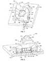
- FIG. 1is a top perspective view of a socket assembly formed in accordance with an exemplary embodiment.
- FIG. 2is a partial cutaway view of the socket assembly shown in FIG. 1 .
- FIG. 3is a top perspective view of an alternative socket assembly formed in accordance with an exemplary embodiment.
- FIG. 4is a top perspective view of another alternative socket assembly formed in accordance with an exemplary embodiment.
- FIG. 5is a top perspective view of a socket housing and thermal management structure for the socket assembly shown in FIG. 4 .
- FIG. 6is a top perspective view of yet another alternative socket assembly formed in accordance with an exemplary embodiment.
- FIG. 7is a top perspective view of a socket housing and thermal management structure for the socket assembly shown in FIG. 6 .
- FIG. 8is a bottom perspective view of another alternative socket assembly formed in accordance with an exemplary embodiment.
- FIG. 9is a top perspective view of yet another alternative socket assembly formed in accordance with an exemplary embodiment.
- FIG. 10is a top perspective view of a thermal management structure for the socket assembly shown in FIG. 9 .
- FIG. 11is a top perspective view of another alternative socket assembly formed in accordance with an exemplary embodiment.
- FIG. 12is a top perspective view of a socket housing and thermal management structure for the socket assembly shown in FIG. 11 .
- FIG. 13is a partial cutaway view of an alternative socket assembly formed in accordance with an exemplary embodiment.
- FIG. 1is a top perspective view of a socket assembly 100 formed in accordance with an exemplary embodiment.
- FIG. 2is a partial cutaway view of the socket assembly 100 .
- the assembly 100is part of a light engine that is used for residential, commercial or industrial use.
- the assembly 100may be used for general purpose lighting, or alternatively, may have a customized application or end use.
- the assembly 100includes a lighting package 102 that is removably received in a receptacle 104 of a socket housing 106 .
- a thermal management structure 108is coupled to the socket housing 106 and is positioned at the receptacle 104 in thermal engagement with the lighting package 102 .
- the thermal management structure 108is configured to engage a heat sink 110 to dissipate heat from the lighting package 102 to the heat sink 110 .
- the lighting package 102includes a solid state lighting device, represented in FIGS. 1 and 2 by a light emitting diode (LED) 114 .
- the LED 114includes an electrical power interface 116 and a thermal interface 118 .
- the power interface 114engages power contacts 120 held by the socket housing 106 . Power is transferred across the power interface 116 to power the LED 114 . Power is supplied to the power contacts 120 by a power connector 122 that is coupled to the socket housing 106 .
- power interfaces 116are provided on opposite edges of the LED 114 , which interface with power contacts 120 on opposites sides of the receptacle 104 .
- Two power connectors 122are coupled to the socket housing 106 , which engage corresponding sets of the power contacts 120 .
- the thermal interface 118engages the thermal management structure 108 .
- the thermal interface 118extends along opposite edges of the LED 114 and along the bottom of the LED 114 .
- the thermal management structure 108engages both the edges and the bottom to dissipate heat from the LED 114 .
- the thermal interface 118may be characterized as having a high thermal conductivity to facilitate good heat transfer at the thermal interface 118 .
- the thermal interface 118may be plated with a metal material.
- the thermal management structure 108includes a mating interface 124 that engages the thermal interface 118 of the LED 114 .
- the thermal management structure 108is manufactured from a metal material, such as copper, aluminum, a metal alloy, and the like.
- the thermal management structure 108includes compliant beams 126 that engage the LED 114 .
- the compliant beams 126ensure good thermal contact between the thermal interface 118 and the mating interface 124 .
- the compliant beams 126may define latches to secure the LED 114 within the receptacle 104 , and thus may be referred to hereinafter as latches 126 .
- the latches 126engage a top surface of the LED 114 to hold the LED 114 within the receptacle 104 .
- the latches 126force the LED 114 downward within the receptacle 104 into engagement with a base 128 of the thermal management structure 108 .
- the base 128thermally engages the bottom of the LED 114 to facilitate thermal transfer of heat from the LED 114 to the thermal management structure 108 , and ultimately to the heat sink 110 .
- the socket housing 106includes a top 130 and a bottom 132 .
- the top 130is open and is configured to receive the lighting package 102 therethrough into the receptacle 104 .
- the bottom 132may rest on a support structure, such as the heat sink 110 or another structure of the lighting fixture.
- the bottom 132is open below the receptacle 104 such that the lighting package 102 may rest on the thermal management structure 108 .
- the socket housing 106includes an upper housing 134 and a lower housing 136 coupled together.
- the power contacts 120are held between the upper and lower housings 134 , 136 , and may be loaded between the upper and lower housings 134 , 136 prior to coupling the upper and lower housings 134 , 136 together. As such, the power contacts 120 may be held internal to the socket housing 106 . The power contacts 120 are positioned such that the power contacts 120 are exposed to the receptacle 104 . As such, when the LED 114 is loaded into the receptacle 104 , the power contacts 120 engage the LED 114 .
- the socket housing 106includes connector ports 138 that receive the power connectors 122 .
- the power contacts 120may be exposed within the connector ports 138 such that the power connectors 122 engage the power contacts 120 when the power connectors 122 are loaded into the connector ports 138 .
- the socket housing 106may include securing features 140 at the connector ports 138 to hold the power connectors 122 within the connector ports 138 .
- the socket housing 106includes mounting features 142 used to secure the socket housing 106 to the heat sink 110 .
- the mounting features 142may include openings that receive fasteners (not shown).
- Alternative types of mounting featuresmay be used in alternative embodiments, such as clips.
- the LED package 102 , the socket housing 106 , and the thermal management structure 108together define an individual socket 150 of the assembly 100 .
- Any number of sockets 150may be combined to form the assembly 100 .
- the sockets 150may be ganged together or may be daisy-chained together.
- the sockets 150may be physically connected together in addition to being electrically connected together.
- the sockets 150may be assembled together prior to being mounted to the heat sink 110 .
- the thermal management structure 108may be coupled to the socket housing 106 , and then the lighting package 102 loaded into the receptacle 104 . Once assembled, the socket 150 may be handled as a single unit, and moved to the appropriate location on the heat sink 110 and mounted thereto.
- the thermal management structure 108is an integral part of the socket 150 and may be mounted to the heat sink 110 during the same mounting step as the socket housing 106 . Once mounted, the thermal management structure 108 engages the heat sink 110 and defines the thermal path between the lighting package 102 and the heat sink 110 .
- the thermal management structure 108may be used as the only thermal interface between the sockets 150 and the heat sink 110 . No other thermal interconnect is required. For example, no thermal grease, thermal epoxy or thermal pad need be positioned between the lighting package 102 and the heat sink 110 .
- the socket 150may be quickly mounted to the heat sink 110 .
- the socket 150is easy and clean to handle and work with.
- the socket 150may be easily repaired and replaced, such as by removing the socket 150 from the heat sink 110 , and without thermal grease or epoxy between the socket 150 and the heat sink 110 , the removal is clean and easy.
- just the lighting package 102may be removed from the receptacle 104 , while the socket housing 106 and thermal management structure 108 remain in place, mounted to the heat sink 110 .
- the lighting packages 102e.g. to replace a defective or burnt out LED 114 , for a different lighting effect, and the like
- FIG. 3is a top perspective view of an alternative socket assembly 200 formed in accordance with an exemplary embodiment.
- the assembly 200includes a lighting package 202 that is removably received in a receptacle 204 of a socket housing 206 .
- a thermal management structure 208is coupled to the socket housing 206 and is positioned at the receptacle 204 in thermal engagement with the lighting package 202 .
- the thermal management structure 208is configured to engage a heat sink (not shown) to dissipate heat from the lighting package 202 to the heat sink.
- the lighting package 202 and thermal management structure 208are similar to the lighting package 102 and thermal management structure 108 (both shown in FIGS.
- socket housing 206differs from the socket housing 106 (shown in FIGS. 1 and 2 ).
- the LED package 202 , the socket housing 206 , and the thermal management structure 208together define an individual socket 210 of the assembly 200 . Any number of sockets 210 may be combined to form the assembly 200 . In the illustrated embodiment, two sockets 210 are ganged together, such that the sockets 210 are mechanically and electrically coupled to one another.
- the socket housing 206includes a first connector 220 and a second connector 222 at opposite ends of the socket housing 206 .
- the first and second connectors 220 , 222are configured to engage connectors 222 , 220 , respectively of an adjacent socket 210 .
- the first and second connectors 220 , 222are also configured to engage power connectors 224 , 226 .
- individual sockets 210may be ganged together, with the power connectors 224 , 226 being coupled to the outermost connectors 220 , 222 , respectively.
- a modular systemis provided, with individual sockets 210 being arranged end-to-end in series. Power is transferred between the connectors 220 , 222 of adjacent sockets 210 .
- the first connector 220includes power contacts 228 that are exposed at a first edge 230 of the socket housing 206 and that are exposed within the receptacle 204 .
- the lighting package 202engages the power contacts 228 .
- Either the first power connector 224 or a second connector 222 of an adjacent socket 210is configured to engage the power contacts 228 at the edge 230 .
- the first connector 220includes securing features 232 for securing the first power connector 224 or the second connector 222 to the first connector 220 .
- the securing features 232represent protrusions.
- the second connector 222includes power contacts 234 that are exposed at a second edge 236 of the socket housing 206 and that are exposed within the receptacle 204 .
- the lighting package 202engages the power contacts 234 .
- Either the second power connector 226 or a first connector 220 of an adjacent socket 210is configured to engage the power contacts 234 at the edge 236 .
- the second connector 222includes securing features 238 for securing the second power connector 226 or the first connector 220 to the second connector 222 .
- the securing features 238represent pockets that receive the protrusions of the securing features 232 .
- the second power connector 226includes a contact 240 terminated to an end of a wire 242 .
- the second power connector 226also includes a body 244 having a channel 246 that receives the contact 240 and wire 242 .
- the contact 240is exposed along an edge of the body 244 for mating with the power contacts 234 of the second connector 222 .
- the body 244includes securing features 248 that are configured to engage the securing features 238 of the second connector 222 to securely couple the second power connector 226 to the second connector 222 .
- the securing features 248represent protrusions that are received in the pockets of the securing features 238 .
- the first power connector 224is similar to the second power connector 226 , however the first power connector 224 includes securing features 250 that are configured to engage the securing features 232 of the first connector 220 to securely couple the first power connector 224 to the first connector 220 .
- the securing features 250represent pockets that receive the protrusions of the securing features 232 .
- the sockets 210may be assembled together prior to being mounted to the heat sink.
- the thermal management structure 208may be coupled to the socket housing 206 , and then the lighting package 202 loaded into the receptacle 204 . Once assembled, the socket 210 may be handled as a single unit, and moved to the appropriate location on the heat sink and mounted thereto. As a result, the thermal management structure 208 is an integral part of the socket 210 and may be mounted to the heat sink during the same mounting step as the socket housing 206 . Once mounted, the thermal management structure 208 engages the heat sink and defines the thermal path between the lighting package 202 and the heat sink.
- the power connectors 224 , 226may be connected to the sockets 210 either before or after the sockets 210 are mounted to the heat sink.
- FIG. 4is a top perspective view of another alternative socket assembly 300 formed in accordance with an exemplary embodiment.
- FIG. 5is an exploded view of a portion of the socket assembly 300 .
- the assembly 300includes a lighting package 302 that is removably received in a receptacle 304 of a socket housing 306 .
- a thermal management structure 308(shown in FIG. 5 ) is coupled to the socket housing 306 and is positioned at the receptacle 304 in thermal engagement with the lighting package 302 .
- the thermal management structure 308is configured to engage a heat sink (not shown) to dissipate heat from the lighting package 302 to the heat sink.
- the lighting package 302 , the socket housing 306 , and the thermal management structure 308together define an individual socket 310 of the assembly 300 .
- Any number of sockets 310may be combined to form the assembly 300 .
- three sockets 310are ganged together, such that the sockets 310 are mechanically and electrically coupled to one another.
- Each lighting package 302includes a lighting printed circuit board (PCB) 312 received in the receptacle 304 .
- the lighting PCBs 312have electronic components 314 mounted thereto.
- the electronic components 314may be LEDs 316 .
- the electronic components 314may additionally or alternatively include microprocessors, capacitors, circuit protection devices, resistors, transistors, integrated circuit, and the like that create an electronic circuit or control circuit with a particular control function (e.g. wireless control, filtering, circuit protection, light control, and the like).
- the lighting PCB 312includes a power interface 320 and a thermal interface 322 .
- the power interface 320engages power contacts 324 held by the socket housing 306 . Power is transferred across the power interface 320 to power the electronic components 314 (shown in FIG. 4 ).
- the power interface 320includes a plurality of power pads 326 on a bottom surface 328 of the lighting PCB 312 that interface with corresponding power contacts 324 .
- the thermal interface 322engages the thermal management structure 308 , which is held by the socket housing 306 at a bottom of the receptacle 304 .
- the thermal management structure 308is represented by a heat slug, which is a solid metal block held by the socket housing 306 and that extends to a bottom 330 of the socket housing 306 .
- a bottom of the thermal management structure 308may flare out to have a larger surface area than a top of the thermal management structure 308 .
- the bottom of the thermal management structure 308engages the heat sink when the socket housing 306 is mounted thereto.
- the top of the thermal management structure 308defines a mating interface 332 that engages the thermal interface 322 when the LED PCB 312 is loaded into the receptacle 304 .
- the socket housing 306includes a first mating end 334 and an opposite second mating end 336 .
- the mating ends 334 , 336are hermaphroditic.
- the mating ends 334 , 336having separable mating interfaces, which may be substantially identical to one another such that the first mating end 334 is configured to mate with either the first or second mating end 334 , 336 of an adjacent socket 310 .
- the mating ends 334 , 336include hooks 338 on one side thereof and pockets 340 on the other side thereof. The hooks 338 are configured to be received in the pockets 340 of an adjacent socket 310 .
- the socket housing 306includes a plurality of the power contacts 324 at each of the mating ends 334 , 336 exposed on the exterior edges of the socket housing 306 .
- the power contacts 324extend into the receptacle 304 for mating with the lighting PCB 312 .
- the power contacts 324may be compliant beams that deflect when engaging corresponding power pads 326 , or corresponding power contacts 324 of an adjacent socket 310 .
- the socket housing 306may include fasteners to secure the socket housing 306 to the heat sink. Once secured, the lighting PCB 312 may be removed from the receptacle 304 and replaced with a different lighting PCB 312 .
- the sockets 310may be assembled together prior to being mounted to the heat sink.
- the thermal management structure 308may be coupled to the socket housing 306 , and then the lighting package 302 loaded into the receptacle 304 .
- the socket 310may be handled as a single unit, and moved to the appropriate location on the heat sink and mounted thereto.
- the thermal management structure 308is an integral part of the socket 310 and may be mounted to the heat sink during the same mounting step as the socket housing 306 . Once mounted, the thermal management structure 308 engages the heat sink and defines the thermal path between the lighting package 302 and the heat sink.
- a power connector 342may be coupled to either mating end 334 , 336 rather than an adjacent socket 310 .
- the socket 310 arranged at the upstream end of the assembly 300may be connected to a power connector 342 .
- the power connector 342supplies power to the assembly 300 , such as from a power source.
- the power connector 342may be connected to the sockets 310 either before or after the sockets 310 are mounted to the heat sink.
- FIG. 6is a top perspective view of yet another alternative socket assembly 400 formed in accordance with an exemplary embodiment.
- FIG. 7is a top perspective view of a portion of the socket assembly 400 .
- the assembly 400includes a lighting package 402 that is removably received in a receptacle 404 of a socket housing 406 .
- a thermal management structure 408is coupled to the socket housing 406 and is positioned at the receptacle 404 in thermal engagement with the lighting package 402 .
- the thermal management structure 408is configured to engage a heat sink (not shown) to dissipate heat from the lighting package 402 to the heat sink.
- the lighting package 402 , the socket housing 406 , and the thermal management structure 408together define an individual socket 410 of the assembly 400 .
- Any number of sockets 410may be combined to form the assembly 400 , such as by being ganged or daisy-chained together.
- the lighting package 402includes a lighting printed circuit board (PCB) 412 received in the receptacle 404 .
- the lighting PCB 412has one or more electronic components 414 mounted thereto.
- the electronic component 414may be an LED.
- the electronic component 414may additionally or alternatively include one or more of microprocessors, capacitors, circuit protection devices, resistors, transistors, integrated circuit, and the like that create an electronic circuit or control circuit with a particular control function (e.g. wireless control, filtering, circuit protection, light control, and the like).
- the lighting PCB 412includes a power interface 420 and a thermal interface 422 .
- the power interface 420includes power contacts 424 that interface with corresponding contacts (not shown) of a power connector 426 . Power is transferred across the power interface 420 to power the electronic components 414 .
- the power connectors 426are received in corresponding connector ports 428 in the socket housing 406 to mate directly to the lighting PCB 412 .
- the thermal interface 422engages the thermal management structure 408 , which is held by the socket housing 406 at a bottom of the receptacle 404 .
- the thermal management structure 408is represented by a metal plate attached to the socket housing 406 at a bottom of the receptacle 406 .
- the thermal management structure 408forms part of the receptacle 406 .
- the thermal management structure 408may include supporting elements 430 in the form of walls and/or latches that support the lighting PCB 412 .
- the thermal management structure 408also includes a base 432 that extends along the bottom of the receptacle 404 . The base 432 supports the lighting PCB 412 from below.
- the base 432includes a plurality of fingers 434 that extend upward from the base 432 into the receptacle 404 .
- the fingers 434are compliant beams that deflect when the lighting PCB 412 is loaded into the receptacle 404 .
- the fingers 434are biased against the lighting PCB 412 and maintain thermal engagement with the lighting PCB 412 when the lighting PCB 412 is loaded into the receptacle 404 .
- Heatis transferred to the base 432 by the fingers 434 .
- the base 432engages the heat sink when the socket housing 406 is mounted thereto.
- the base 432may also include fingers that extend downward and engage the heat sink.
- two electrical power connectors 426are coupled to the individual socket 410 .
- One of the power connectors 426brings power into the socket 410 , such as from a power source or from another upstream socket 410 .
- the other power connector 426takes power out of the socket 410 , such as to a downstream socket 410 .
- the power connectors 426are provided at cable ends. Any number of sockets 410 may be provided and electrically connected using the power connectors 426 and corresponding cables to form the assembly 400 .
- the sockets 410may be assembled together prior to being mounted to the heat sink.
- the thermal management structure 408may be coupled to the socket housing 406 , and then the lighting package 402 loaded into the receptacle 404 .
- the socket 410may be handled as a single unit, and moved to the appropriate location on the heat sink and mounted thereto.
- the thermal management structure 408is an integral part of the socket 410 and may be mounted to the heat sink during the same mounting step as the socket housing 406 . Once mounted, the thermal management structure 408 engages the heat sink and defines the thermal path between the lighting package 402 and the heat sink.
- the power connectors 426may be connected to the sockets 410 either before or after the sockets 410 are mounted to the heat sink.
- FIG. 8is a top perspective view of yet another alternative socket assembly 500 formed in accordance with an exemplary embodiment.
- the assembly 500includes a lighting package 502 that is removably received in a receptacle 504 of a socket housing 506 .
- a thermal management structure 508is coupled to the socket housing 506 and is positioned at the receptacle 504 in thermal engagement with the lighting package 502 .
- the lighting package 502 and socket housing 506are similar to the lighting package 402 and socket housing 406 (both shown in FIGS. 6 and 7 ), however the thermal management structure 508 differs from the thermal management structure 308 (shown in FIGS. 6 and 7 ).
- the thermal management structure 508includes an integral heat sink 510 extending therefrom.
- the thermal management structure 508includes a base 512 and fingers (not shown, but similar to the fingers 434 shown in FIG. 7 ) that extend upward and/or downward from the base 512 to engage the lighting package 502 .
- the base 512may include mounting features (not shown) that engage the socket housing 506 to securely couple the thermal management structure 508 to the socket housing 506 .
- the mounting featuresmay extend into slots in the bottom of the socket housing 506 and engage the socket housing 506 in an interference fit to secure the thermal management structure 508 to the socket housing 506 .
- the heat sink 510is positioned below the base 512 .
- the heat sink 510is formed integral with the base 512 .
- both the base 512 and the heat sink 510are stamped and formed from a common piece of metal.
- the heat sink 510is formed and shaped to facilitate heat dissipation therefrom.
- the heat sink 510includes a plurality of fins 520 that are angled with respect to the base 512 .
- the fins 520may be angled perpendicular to the base 512 or at non-orthogonal angles with respect to the base 512 .
- the heat sink 512has an overall surface area that is greater than the surface area of the base 512 .
- the surface area of the heat sink 510is approximately 5 times the surface area of the base 512 , with each fin 520 having a first side and a second side, and with 5 total number of fins 520 being provided.
- the surface area of one side of each fin 520is approximately half the surface area of the base 512 . It is realized that any number of fins 520 may be provided in alternative embodiments. Additionally, the fins 520 may have any relative size compared to the base 512 .
- FIG. 9is a top perspective view of another alternative socket assembly 600 formed in accordance with an exemplary embodiment.
- FIG. 10is an exploded view of the socket assembly.
- the assembly 600includes a lighting package 602 that is removably received in a receptacle 604 of a socket housing 606 .
- a thermal management structure 608defines the socket housing 606 and receptacle 604 .
- the thermal management structure 608is in thermal engagement with the lighting package 602 .
- the thermal management structure 608is configured to engage a heat sink (not shown) to dissipate heat from the lighting package 602 to the heat sink.
- the lighting package 602includes a lighting printed circuit board (PCB) 612 received in the receptacle 604 .
- the lighting PCB 612has one or more electronic components 614 mounted thereto.
- the electronic component 614may be an LED.
- the electronic component 614may additionally or alternatively include one or more of microprocessors, capacitors, circuit protection devices, resistors, transistors, integrated circuit, and the like that create an electronic circuit or control circuit with a particular control function (e.g. wireless control, filtering, circuit protection, light control, and the like).
- the lighting PCB 612includes one or more power interface(s) 620 and a thermal interface 622 .
- Each power interface 620includes power contacts 624 that interface with corresponding contacts (not shown) of a power connector 626 . Power is transferred across the power interface 620 to power the electronic components 614 .
- the power contacts 624are held in a connector body 628 that is mounted to the lighting PCB 612 .
- the power connector 626is coupled to the connector body 628 such that mating contacts (not shown) of the power connector 626 engage the power contacts 624 .
- the thermal interface 622engages the thermal management structure 608 .
- the thermal management structure 608is represented by a metal plate, which may be stamped and formed to include a base 630 and a plurality of supporting elements 632 extending from the base 630 .
- the supporting elements 632represent walls that form the socket housing 606 and that define a space defining the receptacle 604 .
- the socket housing 606is formed integral with the thermal management structure 608 .
- the thermal management structure 608is the structure defining the receptacle 604 , as opposed to dielectric body defining the receptacle.
- the supporting elements 632may include latches 634 that secure the lighting PCB 612 within the receptacle 604 .
- the base 630extends along the bottom of the receptacle 604 .
- the base 630supports the lighting PCB 612 from below.
- the base 630includes a plurality of package fingers 636 that extend upward from the base 630 into the receptacle 604 and a plurality of heat sink fingers 638 that extend downward from the base 630 .
- the package fingers 636engage the lighting PCB 612 and the heat sink fingers 638 engage the heat sink.
- the fingers 636 , 638are compliant beams that deflect when loaded against the lighting PCB 612 and heat sink, respectively.
- the fingers 636 , 638are biased against the lighting PCB 612 and heat sink, respectively, and maintain thermal engagement when the lighting PCB 612 is loaded into the receptacle 604 and when the socket 610 is mounted to the heat sink. Heat is transferred to the base 630 by the package fingers 636 , and the heat is transferred from the base 630 to the heat sink by the heat sink fingers 638 .
- an equal number of package fingers 636 and heat sink fingers 638may be provided.
- an unequal number of fingers 636 , 638may be provided.
- the fingers 636 , 638may be the same size, or alternatively, may be sized differently.
- the fingers 636may provide substantially the same biasing force upward as the downward biasing force of the fingers 638 .
- two electrical power connectors 626are coupled to the individual socket 610 .
- One of the power connectors 626brings power into the socket 610 , such as from a power source or from another upstream socket 610 .
- the other power connector 626takes power out of the socket 610 , such as to a downstream socket 610 .
- the power connectors 626are provided at cable ends. Any number of sockets 610 may be provided and electrically connected using the power connectors 626 and corresponding cables to form the assembly 600 .
- the sockets 610may be assembled together prior to being mounted to the heat sink.
- the lighting package 602may be loaded into the receptacle 604 of the thermal management structure 608 and handled as a single unit, and moved to the appropriate location on the heat sink and mounted thereto. Once mounted, the thermal management structure 608 engages the heat sink and defines the thermal path between the lighting package 602 and the heat sink.
- the power connectors 626may be connected to the sockets 610 either before or after the sockets 610 are mounted to the heat sink.
- FIG. 11is a top perspective view of another alternative socket assembly 700 formed in accordance with an exemplary embodiment.
- FIG. 12is an exploded view of the socket assembly.
- the assembly 700includes a lighting package 702 that is removably received in a receptacle 704 of a socket housing 706 .
- a thermal management structure 708defines the socket housing 706 and receptacle 704 .
- the thermal management structure 708is in thermal engagement with the lighting package 702 .
- the thermal management structure 708is configured to engage a heat sink (not shown) to dissipate heat from the lighting package 702 to the heat sink.
- the thermal management structure 708is similar to the thermal management structure 608 (shown in FIGS. 9 and 10 ), however the thermal management structure 708 includes different structural features.
- the thermal management structure 708includes a base 730 and a plurality of supporting elements 732 extending from the base 730 .
- the supporting elements 732represent walls that form the socket housing 706 and that define a space defining the receptacle 704 .
- the socket housing 706is formed integral with the thermal management structure 708 .
- the thermal management structure 708is the structure defining the receptacle 704 .
- the supporting elements 732may include latches 734 that secure the lighting PCB 712 within the receptacle 704 .
- At least one of the supporting elements 732includes a ledge 736 . The lighting package 702 is received under the ledge 736 to hold the lighting package 702 within the receptacle 704 .
- the supporting elements 732 extending along the sides of the lighting package 702include deflectable thermal arms 738 that engage the sides of the lighting package 702 .
- the thermal arms 738are in thermal engagement with the sides to dissipate heat from the lighting package 702 .
- the sides of the lighting package 702may be plated to improve thermal conductivity along the sides thereof.
- the base 730extends along the bottom of the receptacle 704 .
- the base 730supports the lighting package 702 from below.
- the base 730includes a plurality of package fingers 740 that extend upward from the base 730 into the receptacle 704 and a plurality of heat sink fingers 742 that extend downward from the base 730 .
- the package fingers 740engage the lighting package 702 and the heat sink fingers 742 engage the heat sink.
- FIG. 13is a partial cutaway view of yet another alternative socket assembly 800 formed in accordance with an exemplary embodiment.
- the assembly 800includes a lighting package 802 that is removably received in a receptacle 804 of a socket housing 806 .
- a thermal management structure 808is coupled to the socket housing 806 and is positioned at the receptacle 804 in thermal engagement with the lighting package 802 .
- the thermal management structure 808is configured to engage a heat sink 810 to dissipate heat from the lighting package 802 to the heat sink 810 .
- the lighting package 802includes a lighting printed circuit board (PCB) 812 received in the receptacle 804 .
- the lighting PCB 812has one or more electronic components 814 mounted thereto.
- the electronic component 814may be an LED.
- the electronic component 814may additionally or alternatively include one or more of microprocessors, capacitors, circuit protection devices, resistors, transistors, integrated circuit, and the like that create an electronic circuit or control circuit with a particular control function (e.g. wireless control, filtering, circuit protection, light control, and the like).
- the lighting PCB 812includes a power interface 820 and a thermal interface 822 .
- the power interface 820includes power contacts 824 that interface with corresponding mating contacts 825 of power connectors 826 . Power is transferred across the power interface 820 to power the electronic components 814 .
- the power connectors 826are received in corresponding connector ports 828 in the socket housing 806 to mate directly to the lighting PCB 812 .
- the thermal interface 822engages the thermal management structure 808 , which is held by the power connectors 826 at a bottom of the receptacle 804 .
- the thermal management structure 808is represented by a metal base 830 attached to a dielectric body 832 of the power connector 826 .
- the thermal management structure 808includes fingers 834 extending forward of the base 830 .
- the fingers 834engage the bottom of the lighting PCB 812 at the thermal interface 822 .
- the fingers 834are compliant beams that deflect when mated with the lighting PCB 812 to ensure good thermal engagement against the bottom of the lighting PCB 812 .
- the fingers 834When the power connector 826 is mated with the socket housing 806 , the fingers 834 are biased against the heat sink 810 and maintain thermal engagement with the heat sink 810 . Heat is transferred by the fingers 834 from the thermal interface 822 to the heat sink 810 when the power connector 826 is plugged into the socket housing 806 .
- two power connectors 826are coupled to the individual socket housing 806 .
- One of the power connectors 826brings power into the socket housing 806 , such as from a power source or from another upstream socket housing 806 .
- the other power connector 826takes power out of the socket housing 806 .
- the power connectors 826are provided at cable ends. Any number of socket housings 806 and lighting packages 802 may be provided and electrically connected using the power connectors 826 and corresponding cables to form the assembly 800 .
- the thermal management structure 808is an integral part of the power connectors 826 and is connected to the lighting PCB 812 when the power connector 826 is coupled to the socket housing 806 . Once mated, the thermal management structure 808 engages the heat sink 810 and defines the thermal path between the lighting package 802 and the heat sink 810 .
Landscapes
- Engineering & Computer Science (AREA)
- General Engineering & Computer Science (AREA)
- Arrangement Of Elements, Cooling, Sealing, Or The Like Of Lighting Devices (AREA)
- Non-Portable Lighting Devices Or Systems Thereof (AREA)
- Connecting Device With Holders (AREA)
- Led Device Packages (AREA)
- Fastening Of Light Sources Or Lamp Holders (AREA)
Abstract
Description
Claims (16)
Priority Applications (5)
| Application Number | Priority Date | Filing Date | Title |
|---|---|---|---|
| US12/634,542US8210715B2 (en) | 2009-12-09 | 2009-12-09 | Socket assembly with a thermal management structure |
| EP10193884.3AEP2333405B1 (en) | 2009-12-09 | 2010-12-06 | Socket assembly with a thermal management structure |
| JP2010273647AJP5594892B2 (en) | 2009-12-09 | 2010-12-08 | Socket assembly having thermal management structure |
| KR1020100124936AKR101760947B1 (en) | 2009-12-09 | 2010-12-08 | Socket assembly with a thermal management structure |
| CN201010625081.6ACN102162631B (en) | 2009-12-09 | 2010-12-09 | Socket assembly with a thermal management structure |
Applications Claiming Priority (1)
| Application Number | Priority Date | Filing Date | Title |
|---|---|---|---|
| US12/634,542US8210715B2 (en) | 2009-12-09 | 2009-12-09 | Socket assembly with a thermal management structure |
Publications (2)
| Publication Number | Publication Date |
|---|---|
| US20110136374A1 US20110136374A1 (en) | 2011-06-09 |
| US8210715B2true US8210715B2 (en) | 2012-07-03 |
Family
ID=43827549
Family Applications (1)
| Application Number | Title | Priority Date | Filing Date |
|---|---|---|---|
| US12/634,542Active2030-09-24US8210715B2 (en) | 2009-12-09 | 2009-12-09 | Socket assembly with a thermal management structure |
Country Status (5)
| Country | Link |
|---|---|
| US (1) | US8210715B2 (en) |
| EP (1) | EP2333405B1 (en) |
| JP (1) | JP5594892B2 (en) |
| KR (1) | KR101760947B1 (en) |
| CN (1) | CN102162631B (en) |
Cited By (10)
| Publication number | Priority date | Publication date | Assignee | Title |
|---|---|---|---|---|
| US20120156920A1 (en)* | 2010-12-17 | 2012-06-21 | Ken Sakai | LED Connector Assembly and Connector |
| USD689031S1 (en)* | 2011-07-08 | 2013-09-03 | Cree, Inc. | LED chip |
| USD691973S1 (en) | 2011-07-08 | 2013-10-22 | Cree, Inc. | Lamp packages |
| USD703348S1 (en) | 2012-07-09 | 2014-04-22 | Cree, Inc. | Lamp package |
| US8941311B2 (en) | 2013-04-09 | 2015-01-27 | Bombardier Transportation Gmbh | Control of the intensity of a LED lighting system |
| US20160131353A1 (en)* | 2014-11-12 | 2016-05-12 | Ingersoll-Rand Company | Integral tool housing heat sink for light emitting diode apparatus |
| US9593835B2 (en) | 2013-04-09 | 2017-03-14 | Bombardier Transportation Gmbh | LED lighting system for a railway vehicle |
| US10119696B2 (en) | 2007-06-25 | 2018-11-06 | Ingersoll-Rand Company | Amplification circuit and heat sink used with a light emitting apparatus having varying voltages |
| US12111039B2 (en)* | 2022-06-08 | 2024-10-08 | Hyundai Mobis Co., Ltd. | Prefab lighting device |
| WO2024216067A1 (en)* | 2023-04-14 | 2024-10-17 | Bal Seal Engineering, Llc | Spring array frame and related methods |
Families Citing this family (40)
| Publication number | Priority date | Publication date | Assignee | Title |
|---|---|---|---|---|
| US9279543B2 (en)* | 2010-10-08 | 2016-03-08 | Cree, Inc. | LED package mount |
| US9146027B2 (en) | 2011-04-08 | 2015-09-29 | Ideal Industries, Inc. | Device for holding a source of LED light |
| JP5965120B2 (en)* | 2011-09-13 | 2016-08-03 | タイコエレクトロニクスジャパン合同会社 | LED socket |
| JP5499005B2 (en)* | 2011-10-25 | 2014-05-21 | 京セラコネクタプロダクツ株式会社 | Semiconductor light emitting element holder, semiconductor light emitting element module, and lighting fixture |
| US9188316B2 (en)* | 2011-11-14 | 2015-11-17 | Tyco Electronics Corporation | LED socket assembly |
| WO2013131092A1 (en)* | 2012-03-02 | 2013-09-06 | Molex Incorporated | Array holder and led module with same |
| CN104350328B (en)* | 2012-03-02 | 2018-05-11 | 莫列斯公司 | L ED module |
| ITMI20121015A1 (en)* | 2012-06-12 | 2013-12-13 | Arditi Spa | LED CHIP ARRAY LIGHTING SYSTEM WITH HIGH SIMPLICITY OF ASSEMBLY. |
| US8876322B2 (en) | 2012-06-20 | 2014-11-04 | Journée Lighting, Inc. | Linear LED module and socket for same |
| JP5548283B2 (en)* | 2012-10-26 | 2014-07-16 | 株式会社東和化成工業所 | Plastic socket |
| JP5614732B2 (en)* | 2012-12-26 | 2014-10-29 | Smk株式会社 | LED module board connector |
| US9565782B2 (en) | 2013-02-15 | 2017-02-07 | Ecosense Lighting Inc. | Field replaceable power supply cartridge |
| TWI598665B (en)* | 2013-03-15 | 2017-09-11 | 隆達電子股份有限公司 | Light-emitting element, long strip light-emitting element and application thereof |
| DE102013205998A1 (en)* | 2013-04-04 | 2014-10-09 | Osram Gmbh | Optoelectronic assembly and method for manufacturing an optoelectronic assembly |
| DE102013221647A1 (en)* | 2013-04-30 | 2014-10-30 | Tridonic Jennersdorf Gmbh | LED module with converter circuit |
| US9976710B2 (en) | 2013-10-30 | 2018-05-22 | Lilibrand Llc | Flexible strip lighting apparatus and methods |
| KR20150054205A (en)* | 2013-11-11 | 2015-05-20 | 미래엘리디 주식회사 | Light emitted diode module for signboard |
| WO2015101420A1 (en)* | 2014-01-02 | 2015-07-09 | Tyco Electronics Nederland B.V. | Led socket assembly |
| US10477636B1 (en) | 2014-10-28 | 2019-11-12 | Ecosense Lighting Inc. | Lighting systems having multiple light sources |
| US11306897B2 (en) | 2015-02-09 | 2022-04-19 | Ecosense Lighting Inc. | Lighting systems generating partially-collimated light emissions |
| US9869450B2 (en) | 2015-02-09 | 2018-01-16 | Ecosense Lighting Inc. | Lighting systems having a truncated parabolic- or hyperbolic-conical light reflector, or a total internal reflection lens; and having another light reflector |
| US9568665B2 (en) | 2015-03-03 | 2017-02-14 | Ecosense Lighting Inc. | Lighting systems including lens modules for selectable light distribution |
| US9651227B2 (en) | 2015-03-03 | 2017-05-16 | Ecosense Lighting Inc. | Low-profile lighting system having pivotable lighting enclosure |
| US9651216B2 (en) | 2015-03-03 | 2017-05-16 | Ecosense Lighting Inc. | Lighting systems including asymmetric lens modules for selectable light distribution |
| US9746159B1 (en) | 2015-03-03 | 2017-08-29 | Ecosense Lighting Inc. | Lighting system having a sealing system |
| JP6481481B2 (en)* | 2015-04-20 | 2019-03-13 | 市光工業株式会社 | Vehicle lighting |
| USD785218S1 (en) | 2015-07-06 | 2017-04-25 | Ecosense Lighting Inc. | LED luminaire having a mounting system |
| USD782094S1 (en) | 2015-07-20 | 2017-03-21 | Ecosense Lighting Inc. | LED luminaire having a mounting system |
| USD782093S1 (en) | 2015-07-20 | 2017-03-21 | Ecosense Lighting Inc. | LED luminaire having a mounting system |
| US9651232B1 (en) | 2015-08-03 | 2017-05-16 | Ecosense Lighting Inc. | Lighting system having a mounting device |
| US11060702B2 (en) | 2016-03-08 | 2021-07-13 | Ecosense Lighting Inc. | Lighting system with lens assembly |
| US10433455B2 (en) | 2016-03-30 | 2019-10-01 | Leviton Manufacturing Co., Inc. | Wiring device with heat removal system |
| US10782316B2 (en)* | 2017-01-09 | 2020-09-22 | Delta Design, Inc. | Socket side thermal system |
| US12388056B1 (en) | 2017-01-27 | 2025-08-12 | Korrus, Inc. | Linear lighting systems and processes |
| WO2018140727A1 (en) | 2017-01-27 | 2018-08-02 | Lilibrand Llc | Lighting systems with high color rendering index and uniform planar illumination |
| US20180328552A1 (en) | 2017-03-09 | 2018-11-15 | Lilibrand Llc | Fixtures and lighting accessories for lighting devices |
| TWI623700B (en)* | 2017-07-11 | 2018-05-11 | Light-emitting diode fixing device | |
| US11041609B2 (en) | 2018-05-01 | 2021-06-22 | Ecosense Lighting Inc. | Lighting systems and devices with central silicone module |
| US11353200B2 (en) | 2018-12-17 | 2022-06-07 | Korrus, Inc. | Strip lighting system for direct input of high voltage driving power |
| WO2023278632A1 (en) | 2021-06-30 | 2023-01-05 | Delta Design, Inc. | Temperature control system including contactor assembly |
Citations (43)
| Publication number | Priority date | Publication date | Assignee | Title |
|---|---|---|---|---|
| US5038255A (en) | 1989-09-09 | 1991-08-06 | Stanley Electric Co., Ltd. | Vehicle lamp |
| US5283716A (en) | 1992-10-16 | 1994-02-01 | Rosemount Inc. | Electrical component support structure |
| US5404282A (en) | 1993-09-17 | 1995-04-04 | Hewlett-Packard Company | Multiple light emitting diode module |
| US5660461A (en) | 1994-12-08 | 1997-08-26 | Quantum Devices, Inc. | Arrays of optoelectronic devices and method of making same |
| DE19818402A1 (en) | 1998-04-24 | 1999-10-28 | Horn Hannes Schulze | Arrangement for illumination and signaling purposes produces light that is friendly to the eye |
| EP1098135A2 (en) | 1999-11-04 | 2001-05-09 | VALEO Beleuchtung Deutschland GmbH | Vehicle light |
| WO2001073844A1 (en) | 2000-03-24 | 2001-10-04 | Gebr. Swoboda Gmbh | Lighting module unit |
| US6318886B1 (en) | 2000-02-11 | 2001-11-20 | Whelen Engineering Company | High flux led assembly |
| US20020113244A1 (en) | 2001-02-22 | 2002-08-22 | Barnett Thomas J. | High power LED |
| US20020114155A1 (en) | 2000-11-24 | 2002-08-22 | Masayuki Katogi | Illumination system and illumination unit |
| US20020176250A1 (en) | 2001-05-26 | 2002-11-28 | Gelcore, Llc | High power led power pack for spot module illumination |
| US20030063463A1 (en) | 2001-10-01 | 2003-04-03 | Sloanled, Inc. | Channel letter lighting using light emitting diodes |
| US20030094893A1 (en) | 2001-09-25 | 2003-05-22 | Patent-Treuhand-Gesellschaft Fur Elektrische Gluhlampen Mbh | Illumination unit having at least one LED as light source |
| US20030112627A1 (en) | 2000-09-28 | 2003-06-19 | Deese Raymond E. | Flexible sign illumination apparatus, system and method |
| US20030189829A1 (en) | 2001-08-09 | 2003-10-09 | Matsushita Electric Industrial Co., Ltd. | LED illumination apparatus and card-type LED illumination source |
| US6667544B1 (en) | 2000-06-30 | 2003-12-23 | Amkor Technology, Inc. | Stackable package having clips for fastening package and tool for opening clips |
| US20040175189A1 (en) | 2003-01-31 | 2004-09-09 | Osram Opto Semiconductors Gmbh | Light-emitting diode carrier |
| US6817735B2 (en) | 2001-05-24 | 2004-11-16 | Matsushita Electric Industrial Co., Ltd. | Illumination light source |
| DE10319525A1 (en) | 2003-04-30 | 2004-11-25 | Lawson Mardon Singen Gmbh | Strip-like arrangement comprises a strip conductor structure and electrically connected electronic components arranged on a strip conductor support which is connected to a covering part |
| US20040252501A1 (en) | 2002-04-24 | 2004-12-16 | Hideo Moriyama | Light source coupler, illuminant device, patterned conductor, and method for manufacturing light source coupler |
| US20040264195A1 (en) | 2003-06-25 | 2004-12-30 | Chia-Fu Chang | Led light source having a heat sink |
| US6911731B2 (en) | 2003-05-14 | 2005-06-28 | Jiahn-Chang Wu | Solderless connection in LED module |
| US20050152146A1 (en) | 2002-05-08 | 2005-07-14 | Owen Mark D. | High efficiency solid-state light source and methods of use and manufacture |
| US20050243558A1 (en) | 2004-04-30 | 2005-11-03 | Guide Corporation | LED assembly with reverse circuit board |
| US6999318B2 (en) | 2003-07-28 | 2006-02-14 | Honeywell International Inc. | Heatsinking electronic devices |
| US20060091410A1 (en) | 2004-11-03 | 2006-05-04 | Chen Chen-Lun H | Low thermal resistance LED package |
| US20060262533A1 (en) | 2005-05-18 | 2006-11-23 | Para Light Electronics Co., Ltd. | Modular light emitting diode |
| US20070025103A1 (en) | 2004-10-20 | 2007-02-01 | Timothy Chan | Method and system for attachment of light emitting diodes to circuitry for use in lighting |
| US20070246712A1 (en) | 2006-04-25 | 2007-10-25 | Samsung Electro-Mechanics Co., Ltd. | Light emitting diode module |
| US7306353B2 (en) | 1999-10-19 | 2007-12-11 | Permlight Products, Inc. | Mounting arrangement for light emitting diodes |
| US7322718B2 (en) | 2003-01-27 | 2008-01-29 | Matsushita Electric Industrial Co., Ltd. | Multichip LED lighting device |
| US7344296B2 (en)* | 2003-02-07 | 2008-03-18 | Matsushita Electric Industrial Co., Ltd. | Socket for led light source and lighting system using the socket |
| US7348604B2 (en) | 2005-05-20 | 2008-03-25 | Tir Technology Lp | Light-emitting module |
| US7400029B2 (en) | 2002-12-16 | 2008-07-15 | Yanchers Inc. | LED illumination system |
| US20080220631A1 (en) | 2005-05-25 | 2008-09-11 | Matsushita Electric Works, Ltd. | Socket for Electronic Component |
| US20080315214A1 (en) | 2007-06-19 | 2008-12-25 | Philips Lumileds Lighting Company, Llc | Solderless Integrated Package Connector and Heat Sink for LED |
| US20090009998A1 (en) | 2007-07-05 | 2009-01-08 | Tyco Electronics Corporation | Wirelessly controlled light emitting display system |
| US20090009103A1 (en) | 2007-07-05 | 2009-01-08 | Tyco Electronics Corporation | Wireless controlled light emitting assembly |
| US20090108281A1 (en) | 2007-10-31 | 2009-04-30 | Cree, Inc. | Light emitting diode package and method for fabricating same |
| US20090130889A1 (en) | 2007-11-20 | 2009-05-21 | Tyco Electronics Corporation | Led socket |
| US7540761B2 (en) | 2007-05-01 | 2009-06-02 | Tyco Electronics Corporation | LED connector assembly with heat sink |
| US20090146919A1 (en) | 2007-12-11 | 2009-06-11 | Kline Daniel S | Large Scale LED Display |
| US7549786B2 (en) | 2006-12-01 | 2009-06-23 | Cree, Inc. | LED socket and replaceable LED assemblies |
Family Cites Families (15)
| Publication number | Priority date | Publication date | Assignee | Title |
|---|---|---|---|---|
| JP2001052837A (en)* | 1999-08-13 | 2001-02-23 | Toshiba Corp | Sheet metal stamped parts and their manufacturing method |
| JP4095463B2 (en)* | 2003-02-13 | 2008-06-04 | 松下電器産業株式会社 | LED light source socket |
| JP4041411B2 (en) | 2003-02-07 | 2008-01-30 | 松下電器産業株式会社 | Rotating socket for card type LED light source |
| CN2729509Y (en)* | 2004-03-08 | 2005-09-28 | 深圳市沃科半导体照明有限公司 | LED combined lamp |
| JP2007141549A (en)* | 2005-11-16 | 2007-06-07 | Koito Mfg Co Ltd | Lamp for vehicle |
| JP2007200697A (en)* | 2006-01-26 | 2007-08-09 | Koito Mfg Co Ltd | Vehicular lamp |
| JP2008016362A (en)* | 2006-07-07 | 2008-01-24 | Koito Mfg Co Ltd | Light emitting module and vehicle lamp |
| JP2008060204A (en)* | 2006-08-30 | 2008-03-13 | Nec Lcd Technologies Ltd | LED backlight unit and liquid crystal display device using the same |
| JP4582100B2 (en)* | 2007-02-15 | 2010-11-17 | パナソニック電工株式会社 | LED package |
| US7621752B2 (en)* | 2007-07-17 | 2009-11-24 | Visteon Global Technologies, Inc. | LED interconnection integrated connector holder package |
| JP4391555B2 (en)* | 2007-09-14 | 2009-12-24 | 日本航空電子工業株式会社 | socket |
| CN201141525Y (en)* | 2007-11-02 | 2008-10-29 | 葛瑞柱 | Assembled LED neon lamp |
| CN101487583B (en)* | 2008-01-16 | 2010-09-29 | 富士迈半导体精密工业(上海)有限公司 | lighting device |
| JP2009200102A (en)* | 2008-02-19 | 2009-09-03 | Stanley Electric Co Ltd | Light-emitting device and fixing device for semiconductor light-emitting device |
| DE202008011979U1 (en)* | 2008-04-01 | 2008-12-11 | Lebensstil Technology Co., Ltd. | Mounting arrangement of a filament |
- 2009
- 2009-12-09USUS12/634,542patent/US8210715B2/enactiveActive
- 2010
- 2010-12-06EPEP10193884.3Apatent/EP2333405B1/enactiveActive
- 2010-12-08KRKR1020100124936Apatent/KR101760947B1/enactiveActive
- 2010-12-08JPJP2010273647Apatent/JP5594892B2/enactiveActive
- 2010-12-09CNCN201010625081.6Apatent/CN102162631B/enactiveActive
Patent Citations (45)
| Publication number | Priority date | Publication date | Assignee | Title |
|---|---|---|---|---|
| US5038255A (en) | 1989-09-09 | 1991-08-06 | Stanley Electric Co., Ltd. | Vehicle lamp |
| US5283716A (en) | 1992-10-16 | 1994-02-01 | Rosemount Inc. | Electrical component support structure |
| US5404282A (en) | 1993-09-17 | 1995-04-04 | Hewlett-Packard Company | Multiple light emitting diode module |
| US5660461A (en) | 1994-12-08 | 1997-08-26 | Quantum Devices, Inc. | Arrays of optoelectronic devices and method of making same |
| DE19818402A1 (en) | 1998-04-24 | 1999-10-28 | Horn Hannes Schulze | Arrangement for illumination and signaling purposes produces light that is friendly to the eye |
| US7306353B2 (en) | 1999-10-19 | 2007-12-11 | Permlight Products, Inc. | Mounting arrangement for light emitting diodes |
| EP1098135A2 (en) | 1999-11-04 | 2001-05-09 | VALEO Beleuchtung Deutschland GmbH | Vehicle light |
| US6318886B1 (en) | 2000-02-11 | 2001-11-20 | Whelen Engineering Company | High flux led assembly |
| WO2001073844A1 (en) | 2000-03-24 | 2001-10-04 | Gebr. Swoboda Gmbh | Lighting module unit |
| US6667544B1 (en) | 2000-06-30 | 2003-12-23 | Amkor Technology, Inc. | Stackable package having clips for fastening package and tool for opening clips |
| US20030112627A1 (en) | 2000-09-28 | 2003-06-19 | Deese Raymond E. | Flexible sign illumination apparatus, system and method |
| US20020114155A1 (en) | 2000-11-24 | 2002-08-22 | Masayuki Katogi | Illumination system and illumination unit |
| US20020113244A1 (en) | 2001-02-22 | 2002-08-22 | Barnett Thomas J. | High power LED |
| US6541800B2 (en) | 2001-02-22 | 2003-04-01 | Weldon Technologies, Inc. | High power LED |
| US6817735B2 (en) | 2001-05-24 | 2004-11-16 | Matsushita Electric Industrial Co., Ltd. | Illumination light source |
| US20020176250A1 (en) | 2001-05-26 | 2002-11-28 | Gelcore, Llc | High power led power pack for spot module illumination |
| US20030189829A1 (en) | 2001-08-09 | 2003-10-09 | Matsushita Electric Industrial Co., Ltd. | LED illumination apparatus and card-type LED illumination source |
| US20030094893A1 (en) | 2001-09-25 | 2003-05-22 | Patent-Treuhand-Gesellschaft Fur Elektrische Gluhlampen Mbh | Illumination unit having at least one LED as light source |
| US20030063463A1 (en) | 2001-10-01 | 2003-04-03 | Sloanled, Inc. | Channel letter lighting using light emitting diodes |
| US20040252501A1 (en) | 2002-04-24 | 2004-12-16 | Hideo Moriyama | Light source coupler, illuminant device, patterned conductor, and method for manufacturing light source coupler |
| US20050152146A1 (en) | 2002-05-08 | 2005-07-14 | Owen Mark D. | High efficiency solid-state light source and methods of use and manufacture |
| US7400029B2 (en) | 2002-12-16 | 2008-07-15 | Yanchers Inc. | LED illumination system |
| US7322718B2 (en) | 2003-01-27 | 2008-01-29 | Matsushita Electric Industrial Co., Ltd. | Multichip LED lighting device |
| US20040175189A1 (en) | 2003-01-31 | 2004-09-09 | Osram Opto Semiconductors Gmbh | Light-emitting diode carrier |
| US7344296B2 (en)* | 2003-02-07 | 2008-03-18 | Matsushita Electric Industrial Co., Ltd. | Socket for led light source and lighting system using the socket |
| DE10319525A1 (en) | 2003-04-30 | 2004-11-25 | Lawson Mardon Singen Gmbh | Strip-like arrangement comprises a strip conductor structure and electrically connected electronic components arranged on a strip conductor support which is connected to a covering part |
| US6911731B2 (en) | 2003-05-14 | 2005-06-28 | Jiahn-Chang Wu | Solderless connection in LED module |
| US20040264195A1 (en) | 2003-06-25 | 2004-12-30 | Chia-Fu Chang | Led light source having a heat sink |
| US6999318B2 (en) | 2003-07-28 | 2006-02-14 | Honeywell International Inc. | Heatsinking electronic devices |
| US20050243558A1 (en) | 2004-04-30 | 2005-11-03 | Guide Corporation | LED assembly with reverse circuit board |
| US20070025103A1 (en) | 2004-10-20 | 2007-02-01 | Timothy Chan | Method and system for attachment of light emitting diodes to circuitry for use in lighting |
| US20060091410A1 (en) | 2004-11-03 | 2006-05-04 | Chen Chen-Lun H | Low thermal resistance LED package |
| US20060262533A1 (en) | 2005-05-18 | 2006-11-23 | Para Light Electronics Co., Ltd. | Modular light emitting diode |
| US7348604B2 (en) | 2005-05-20 | 2008-03-25 | Tir Technology Lp | Light-emitting module |
| US20080220631A1 (en) | 2005-05-25 | 2008-09-11 | Matsushita Electric Works, Ltd. | Socket for Electronic Component |
| US7553162B2 (en) | 2005-05-25 | 2009-06-30 | Panasonic Electric Works Co., Ltd. | Socket for electronic component |
| US20070246712A1 (en) | 2006-04-25 | 2007-10-25 | Samsung Electro-Mechanics Co., Ltd. | Light emitting diode module |
| US7549786B2 (en) | 2006-12-01 | 2009-06-23 | Cree, Inc. | LED socket and replaceable LED assemblies |
| US7540761B2 (en) | 2007-05-01 | 2009-06-02 | Tyco Electronics Corporation | LED connector assembly with heat sink |
| US20080315214A1 (en) | 2007-06-19 | 2008-12-25 | Philips Lumileds Lighting Company, Llc | Solderless Integrated Package Connector and Heat Sink for LED |
| US20090009998A1 (en) | 2007-07-05 | 2009-01-08 | Tyco Electronics Corporation | Wirelessly controlled light emitting display system |
| US20090009103A1 (en) | 2007-07-05 | 2009-01-08 | Tyco Electronics Corporation | Wireless controlled light emitting assembly |
| US20090108281A1 (en) | 2007-10-31 | 2009-04-30 | Cree, Inc. | Light emitting diode package and method for fabricating same |
| US20090130889A1 (en) | 2007-11-20 | 2009-05-21 | Tyco Electronics Corporation | Led socket |
| US20090146919A1 (en) | 2007-12-11 | 2009-06-11 | Kline Daniel S | Large Scale LED Display |
Cited By (12)
| Publication number | Priority date | Publication date | Assignee | Title |
|---|---|---|---|---|
| US10119696B2 (en) | 2007-06-25 | 2018-11-06 | Ingersoll-Rand Company | Amplification circuit and heat sink used with a light emitting apparatus having varying voltages |
| US20120156920A1 (en)* | 2010-12-17 | 2012-06-21 | Ken Sakai | LED Connector Assembly and Connector |
| US9153882B2 (en)* | 2010-12-17 | 2015-10-06 | Tyco Electronics Japan G.K. | Connector having a cylindrical section with a contact connected to an electrical wire therein |
| USD689031S1 (en)* | 2011-07-08 | 2013-09-03 | Cree, Inc. | LED chip |
| USD691973S1 (en) | 2011-07-08 | 2013-10-22 | Cree, Inc. | Lamp packages |
| USD703348S1 (en) | 2012-07-09 | 2014-04-22 | Cree, Inc. | Lamp package |
| US8941311B2 (en) | 2013-04-09 | 2015-01-27 | Bombardier Transportation Gmbh | Control of the intensity of a LED lighting system |
| US9593835B2 (en) | 2013-04-09 | 2017-03-14 | Bombardier Transportation Gmbh | LED lighting system for a railway vehicle |
| US20160131353A1 (en)* | 2014-11-12 | 2016-05-12 | Ingersoll-Rand Company | Integral tool housing heat sink for light emitting diode apparatus |
| US10486291B2 (en)* | 2014-11-12 | 2019-11-26 | Ingersoll-Rand Company | Integral tool housing heat sink for light emitting diode apparatus |
| US12111039B2 (en)* | 2022-06-08 | 2024-10-08 | Hyundai Mobis Co., Ltd. | Prefab lighting device |
| WO2024216067A1 (en)* | 2023-04-14 | 2024-10-17 | Bal Seal Engineering, Llc | Spring array frame and related methods |
Also Published As
| Publication number | Publication date |
|---|---|
| EP2333405A2 (en) | 2011-06-15 |
| JP2011142312A (en) | 2011-07-21 |
| KR20110065408A (en) | 2011-06-15 |
| CN102162631B (en) | 2017-04-12 |
| JP5594892B2 (en) | 2014-09-24 |
| KR101760947B1 (en) | 2017-07-24 |
| EP2333405B1 (en) | 2017-08-23 |
| CN102162631A (en) | 2011-08-24 |
| EP2333405A3 (en) | 2014-01-22 |
| US20110136374A1 (en) | 2011-06-09 |
Similar Documents
| Publication | Publication Date | Title |
|---|---|---|
| US8210715B2 (en) | Socket assembly with a thermal management structure | |
| JP5682953B2 (en) | LED socket assembly | |
| US8240887B2 (en) | LED light module | |
| US8602608B2 (en) | Light module | |
| EP2340393B1 (en) | Led interconnect assembly | |
| JP5669188B2 (en) | LED lighting assembly | |
| EP2423572B1 (en) | Light module | |
| US7892022B2 (en) | Jumper connector for a lighting assembly | |
| WO2008133889A1 (en) | Led connector assembly with heat sink | |
| US8845130B2 (en) | LED socket assembly | |
| JP2012022987A (en) | Light source module and lighting device | |
| US20110115373A1 (en) | Modular led lighting device | |
| CN111734991B (en) | Lighting device | |
| US11563286B2 (en) | Lighting device with plug connection for electrical connection of two circuit boards |
Legal Events
| Date | Code | Title | Description |
|---|---|---|---|
| AS | Assignment | Owner name:TYCO ELECTRONICS CORPORATION, PENNSYLVANIA Free format text:ASSIGNMENT OF ASSIGNORS INTEREST;ASSIGNORS:MOSTOLLER, MATTHEW EDWARD;DAILY, CHRISTOPHER GEORGE;GINGRICH, CHARLES RAYMOND, III;AND OTHERS;REEL/FRAME:023631/0120 Effective date:20091209 | |
| STCF | Information on status: patent grant | Free format text:PATENTED CASE | |
| FPAY | Fee payment | Year of fee payment:4 | |
| AS | Assignment | Owner name:TE CONNECTIVITY CORPORATION, PENNSYLVANIA Free format text:CHANGE OF NAME;ASSIGNOR:TYCO ELECTRONICS CORPORATION;REEL/FRAME:041350/0085 Effective date:20170101 | |
| MAFP | Maintenance fee payment | Free format text:PAYMENT OF MAINTENANCE FEE, 8TH YEAR, LARGE ENTITY (ORIGINAL EVENT CODE: M1552); ENTITY STATUS OF PATENT OWNER: LARGE ENTITY Year of fee payment:8 | |
| AS | Assignment | Owner name:TE CONNECTIVITY SERVICES GMBH, SWITZERLAND Free format text:CHANGE OF ADDRESS;ASSIGNOR:TE CONNECTIVITY SERVICES GMBH;REEL/FRAME:056514/0015 Effective date:20191101 Owner name:TE CONNECTIVITY SERVICES GMBH, SWITZERLAND Free format text:ASSIGNMENT OF ASSIGNORS INTEREST;ASSIGNOR:TE CONNECTIVITY CORPORATION;REEL/FRAME:056514/0048 Effective date:20180928 | |
| AS | Assignment | Owner name:TE CONNECTIVITY SOLUTIONS GMBH, SWITZERLAND Free format text:MERGER;ASSIGNOR:TE CONNECTIVITY SERVICES GMBH;REEL/FRAME:060885/0482 Effective date:20220301 | |
| MAFP | Maintenance fee payment | Free format text:PAYMENT OF MAINTENANCE FEE, 12TH YEAR, LARGE ENTITY (ORIGINAL EVENT CODE: M1553); ENTITY STATUS OF PATENT OWNER: LARGE ENTITY Year of fee payment:12 |