US8210550B2 - Suspension system for baby stroller - Google Patents
Suspension system for baby strollerDownload PDFInfo
- Publication number
- US8210550B2 US8210550B2US12/465,474US46547409AUS8210550B2US 8210550 B2US8210550 B2US 8210550B2US 46547409 AUS46547409 AUS 46547409AUS 8210550 B2US8210550 B2US 8210550B2
- Authority
- US
- United States
- Prior art keywords
- stroller
- elastic member
- elastic
- members
- operable
- Prior art date
- Legal status (The legal status is an assumption and is not a legal conclusion. Google has not performed a legal analysis and makes no representation as to the accuracy of the status listed.)
- Expired - Fee Related, expires
Links
Images


Classifications
- B—PERFORMING OPERATIONS; TRANSPORTING
- B62—LAND VEHICLES FOR TRAVELLING OTHERWISE THAN ON RAILS
- B62B—HAND-PROPELLED VEHICLES, e.g. HAND CARTS OR PERAMBULATORS; SLEDGES
- B62B9/00—Accessories or details specially adapted for children's carriages or perambulators
- B62B9/18—Resilient suspensions of bodies
- B—PERFORMING OPERATIONS; TRANSPORTING
- B62—LAND VEHICLES FOR TRAVELLING OTHERWISE THAN ON RAILS
- B62B—HAND-PROPELLED VEHICLES, e.g. HAND CARTS OR PERAMBULATORS; SLEDGES
- B62B2301/00—Wheel arrangements; Steering; Stability; Wheel suspension
- B62B2301/20—Resilient wheel suspension using springs
Definitions
- the present inventionrelates generally to suspension mechanisms and systems for baby strollers, and in one particular example, to a suspension system including a rotating damper design.
- Strollersare known to employ various types of wheel suspension mechanisms, if employed at all.
- the most common suspension systemutilizes a coil spring surrounding a telescoping tube arrangement.
- Such a telescoping tube arrangementis further typically coupled to a swing arm on a frame part or on a pivot or swivel joint.
- the suspension systemimparts up and down pivotal movement of the swing arms or arms to which the wheel or wheels are attached.
- the wheel suspensionis achieved by this motion being biased against the spring.
- a suspension system including a rotating damper mechanismmay include a first member attached to a stroller frame, a second member disposed co-axially with the first member and operable to rotate relative to the first member, and at least one elastic member (e.g., urethane) positioned between the first and second members for damping motion (e.g., translation and/or rotational motion) therebetween.
- at least one elastic membere.g., urethane
- multiple elastic membersare disposed in a radial pattern between the first and second members.
- the first and second membersmay be attached directly or indirectly to the stroller frame or wheel.
- the suspension systemis tunable and may be initially preloaded to set the spring action of the suspension system at a desired point on a spring rate curve associated with the system.
- the systemmay allow for a selectable spring rate, which may be achieved by having a two stage rotation of the design with two separate rotating elements.
- a first rotating elementis operable to deform the elastic members to affect their starting condition and shape (and thus change the position on a spring rate curve).
- the first rotating elementmay be coupled to a knob or selection device operable by a user to adjust the suspension during use, e.g., over time or based on varying conditions.
- the suspension systemmay include a fixed pivot with a spring element.
- the suspension systemmay include a combination pivot and damper assembly.
- a suspension sub-assemblycomprises at least a first member and an elastic member.
- the elastic membermay be disposed co-axially within or outside of the first member.
- the first membermay further be configured for attachment to a portion of a stroller frame, stroller frame pivot arm, or wheel assembly, and disposed coaxially with a second member, wherein the elastic member is positioned between the first and second members for damping motion (e.g., translation and/or rotational motion) therebetween.
- multiple elastic membersare disposed in a radial pattern between the first and second members.
- the first and second membersmay be attached directly or indirectly to the stroller frame or wheel.
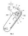
- FIG. 1illustrates a portion of a baby stroller including an exemplary suspension system according to one example
- FIG. 2illustrates a cross-sectional view of an exemplary suspension system
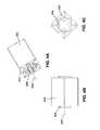
- FIGS. 3A-3Cillustrate perspective, cross-sectional, and side views of an exemplary suspension sub-system
- FIGS. 4A-4Cillustrate perspective, cross-sectional, and side views of an exemplary suspension sub-system according to another example
- FIGS. 5A-5Hillustrate an exemplary suspension adjustment system for use with exemplary suspension systems
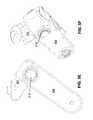
- FIGS. 6A-6Billustrate an exemplary suspension adjustment system for use with exemplary suspension systems
- FIGS. 7A-7Dillustrate an exemplary suspension adjustment system for use with exemplary suspension systems.
- apparatus for a stroller suspension systemincluding a rotating damper mechanism.
- the apparatusincludes a first member positioned coaxially within a second member, where the first and second members are capable of rotation relative to each other, e.g., as part of a pivotjoint.
- the apparatusincludes one or more elastic or damper members positioned between the first and second members for damping relative motion (e.g., rotational or translational motion) of the first and second members.
- the first memberis a rotatable element disposed partially within the second member; however, in other examples the stationary member can be positioned partially within the rotating member.
- the stationary memberis generally referred to as a portion of the baby stroller (or a member generally fixed with respect to the baby stroller frame) and the rotating member a portion of a wheel support (or a member generally fixed with respect to the wheel support); however, it will be recognized that during operation both members may move.
- Various baby strollersmay include a suspension system as described.
- An exemplary strolleris described and shown in U.S. Pat. No. 7,338,122, entitled “Modular Child Restraint System,” which issued on Mar. 4, 2008, and is hereby incorporated by reference in its entirety.
- the exemplary suspension systemmay be used with various other baby strollers, including, but not limited to basinet strollers, jogger strollers, and the like.
- FIG. 1illustrates an exemplary suspension system 130 positioned with a stroller wheel 135 and a frame (not shown) of a baby stroller.
- FIG. 2illustrates a cross-sectional view of the exemplary suspension system.
- a stationary member 101is illustrated with a rotating member 104 disposed coaxially therein, rotating member 104 fixed with respect to structure supporting the stroller wheel as indicated.
- stationary member 101 and rotating member 104are coupled in a pivot joint configuration.
- damper or elastic members 105are disposed between stationary member 101 and rotating member 104 to dampen and/or resist movement of stationary member 101 relative to rotating member 104 about an axis of rotation thereof.
- four elastic members 105are disposed in a radial pattern with respect to the axis of rotation.
- stationary member 101is not stationary in practice and that both stationary member 101 and rotating member 104 move and rotate relative to each other as illustrated.
- elastic members 105may be compressed and triangular shaped as elastic members 505 seen in FIGS. 5G-5H , for example.
- the exemplary suspension systemmay further include a moving suspension member 103 , e.g., a spring, for biasing or resisting rotation of stationary member 101 relative to rotating portion 104 .
- a moving suspension member 103e.g., a spring
- the elastic members 105may be used alone.
- a knob or selection device 112may be operable by a user to adjust the suspension during use, e.g., over time or based on varying conditions, to deform the elastic members 105 and affect their starting condition and shape (and thus change the position on a spring rate curve).
- selection device 112may be included in other configurations, e.g., in-line with the axis of rotation of the joint.
- rotating member 104is positioned within stationary member 101 , where elastic members 105 are disposed between rotating member 104 and stationary member 101 .
- the elastic members 105may be initially compressed in an unloaded state, e.g., with out any torque or load forces from the stroller that may cause relative rotation of the stationary member 101 and rotating member 104 .
- stationary member 101 and rotating member 104will be urged to rotate relative to each other.
- the relative movement between stationary 101 and rotating member 104is damped or resisted by deformation or compression of elastic members 105 .
- Elastic members 105are generally deformed perpendicular to the rotation axis of the system.
- moving suspension member 103may provide further suspension or spring action for the supported stroller.
- the suspension systemincludes multiple elastic members, e.g., four elastic members.
- a single elastic membermay be used (e.g., as seen in FIGS. 4A-4C ), however, three or more elastic members positioned appropriately may provide for a self-centering feature of the rotating and stationary elements.
- elastic elements 105can serve as both a spring and a damper, deriving benefits of compactness and efficiency without having to have two separate elements. Further, in one example, elastic elements 105 may include urethane or another suitable damping material providing for good cold weather performance, rebound/compression/damping performance, chemical resistance, and the like.
- the first and second membersmay include various materials such as injection molded plastic, aluminum, or the like.
- the cross-sectional shape of the opposing surfaces of the first and second membersare shown having a rectangular cross-sectional shape disposed initially offset by 45 degrees.
- different opposing surface shapesmay be used such as triangular, elliptical, circular, oval, polygonal, and the like.
- the cross-sectional shapesdo not need to be the same, e.g., the first member could be rectangular and the second member elliptical.
- the first membere.g., the stationary element 101
- the stationary member 101includes a clamping half 102 which, during assembly, is clamped around the second member 104 and elastic members 105 .
- the designmay provide for ease of manufacturing and cost savings over a non-split design, as well as ease of maintenance or replacement of the second member 104 , elastic members 105 , or the like.
- Other designsare possible and contemplated, e.g., a rotating damper assembly comprising unitary first and second members.
- the exemplary suspension systemsmay also be tuned and/or adjusted.
- a userwhether manufacturer or end-user, may preload the system to achieve different spring constant rates of the system (e.g., to set the spring action at a different point on a spring rate curve associated with the system).
- the systemmay include a selectable spring rate, which may be achieved by having a two stage rotation of the design with two separate rotating elements.
- a first rotating elementis operable to deform the elastic members to affect their starting condition and shape (and thus change the position on a spring rate curve).
- the second rotating elementis operable as described above.
- the first rotating elementmay be coupled to a knob or selection device (such as 112 illustrated in FIG. 2 ) operable by a user to adjust the suspension during use, e.g., over time or based on varying conditions.
- FIGS. 3A-3Cillustrate perspective, cross-sectional, and side views of an exemplary suspension system sub-assembly 300 , which includes structures similar to those shown in FIGS. 1 and 2 .
- sub-assembly 300includes elastic members 305 positioned circumferentially or radially around member 304 , e.g., elastic members disposed in a radial pattern with respect to the axis of rotation of member 304 .
- Member 304may be attached to the stroller frame or wheel assembly, within and co-axially with another member similar to that shown in FIG. 2 .
- one or both endsmay be affixed or fastened to a frame or wheel assembly as described previously.
- sub-assembly 300includes a support member 308 which is included to help secure the arrangement and orientation of elastic members 305 .
- support member 308may secure the position of the elastic members in a generally radial pattern around member 304 , and in this example, offset from a center of the sides of member 304 as seen in FIG. 3C .
- Support member 308may include the same or different material as elastic member 305 and may be formed integrally therewith. Further, support member 308 may include the same or different material as support member 304 and be formed integral therewith.
- suspension system sub-assembliesmay include various configurations and effective spring constants for use with a stroller. Accordingly, a manufacture or user may select different sub-assemblies for use in a common pivot joint depending on various factors such as the type of stroller, intended use, rear wheel versus front wheel, and so on. Additionally, sub-assemblies may be replaced, for example, due to changes in use, weight of a child/seat, or if the spring constant changes over time due to use, exposure to weather (e.g., heat, cold, moisture, etc.), and so on.
- weathere.g., heat, cold, moisture, etc.
- FIGS. 4A-4Cillustrate perspective, cross-sectional, and side views of an exemplary suspension sub-system for a baby stroller.
- This exampleis similar to FIGS. 1 and 2 , however, only a single elastic member 405 is disposed coaxially and circumferentially around member 404 , e.g., in a radial or circular pattern with respect to the axis of rotation of member 404 .
- Elastic member 405is for positioning between member 404 and a second member (as shown with respect to FIG. 2 ).
- a single elastic member 405is disposed to extend circumferentially around member 404 (and in alternate examples, extend circumferentially within a member).
- elastic member 405could be replaced by multiple members extending circumferentially around rotating member 404 .
- elastic member 405may include voids 414 , which may be arranged and positioned to create particular spring constant characteristics of elastic member 405 , reduce the weight of the elastic member 405 , and so on.
- FIGS. 5A-5Hillustrate an exemplary suspension tuning or adjustment system for use with various suspension system examples described herein.
- FIGS. 5A-5Dillustrate an example where inner member 504 (which will be disposed coaxially with or near the axis of rotation) may be expanded radially, thereby changing the amount of preload on the elastic members 505 shown in FIGS. 5G and 5H .
- expanding inner member 504radially causes compression of elastic members 505 , thereby preloading the system.
- Inner member 504may include a single member or four separate elements that can be driven apart by rotation of screw 512 .
- FIGS. 5E-5Fillustrate side views of screw 512 in relation to stationary member 101 and rotating member 104 .
- FIGS. 5G-5Hillustrate cross-sectional side views of inner member 504 and elastic members 505 in relation to stationary member 101 and rotating member 104 .
- a usermay adjust one or both of the screws 512 to expand or compress inner member 504 , thereby changing the characteristics of the suspension system.
- FIGS. 6A-6Billustrate another exemplary suspension tuning or adjustment system for use with various suspension system examples described herein.
- a screw 612is included to adjust the angle of the square cavity-forming members, stationary member 101 and clamping member 102 , which provides additional compression of the elastic members 605 .
- screw 612engages with a member connected to one of the suspension cavity members 102 and/or 104 and is operable to change the angle between the two cavity members 102 and 101 . The change in angle changes the amount of preload on the suspension elements 605 as illustrated in the figures.
- FIGS. 7A-7Dillustrate another exemplary suspension tuning or adjustment system for use with various suspension system examples described herein.
- the inner square memberis made of two separate halves 704 a and 704 b , separated along the longitudinal direction.
- One or more screws 712can be arranged to move the two halves 704 a and 704 b apart from each other along the longitudinal direction to decrease the amount of surface area contacting the elastic members 705 , thus changing the stiffness of the suspension system.
Landscapes
- Engineering & Computer Science (AREA)
- Health & Medical Sciences (AREA)
- Public Health (AREA)
- Chemical & Material Sciences (AREA)
- Combustion & Propulsion (AREA)
- Transportation (AREA)
- Mechanical Engineering (AREA)
- Carriages For Children, Sleds, And Other Hand-Operated Vehicles (AREA)
- Springs (AREA)
Abstract
Description
Claims (24)
Priority Applications (1)
| Application Number | Priority Date | Filing Date | Title |
|---|---|---|---|
| US12/465,474US8210550B2 (en) | 2008-06-09 | 2009-05-13 | Suspension system for baby stroller |
Applications Claiming Priority (2)
| Application Number | Priority Date | Filing Date | Title |
|---|---|---|---|
| US6006008P | 2008-06-09 | 2008-06-09 | |
| US12/465,474US8210550B2 (en) | 2008-06-09 | 2009-05-13 | Suspension system for baby stroller |
Publications (2)
| Publication Number | Publication Date |
|---|---|
| US20090302556A1 US20090302556A1 (en) | 2009-12-10 |
| US8210550B2true US8210550B2 (en) | 2012-07-03 |
Family
ID=41399607
Family Applications (1)
| Application Number | Title | Priority Date | Filing Date |
|---|---|---|---|
| US12/465,474Expired - Fee RelatedUS8210550B2 (en) | 2008-06-09 | 2009-05-13 | Suspension system for baby stroller |
Country Status (1)
| Country | Link |
|---|---|
| US (1) | US8210550B2 (en) |
Cited By (4)
| Publication number | Priority date | Publication date | Assignee | Title |
|---|---|---|---|---|
| CN103009922A (en)* | 2012-12-28 | 2013-04-03 | 胡坚兴 | Caster wheel |
| US10470372B2 (en)* | 2014-07-15 | 2019-11-12 | Pequea Machine, Inc. | Frame suspension for rotary rakes and tedders |
| US10829133B2 (en)* | 2018-07-05 | 2020-11-10 | Faigle Kunststoffe Gmbh | Device comprising a running roller and a suspension system for a running roller |
| US11332180B2 (en) | 2020-01-29 | 2022-05-17 | Guava Family, Inc. | Stroller having compact folding and suspension system |
Families Citing this family (3)
| Publication number | Priority date | Publication date | Assignee | Title |
|---|---|---|---|---|
| WO2012075157A2 (en) | 2010-11-30 | 2012-06-07 | Kolcraft Enterprises, Inc. | Maneuverable strollers |
| CN103909960B (en) | 2013-01-07 | 2016-05-25 | 考可拉夫特公司 | Stroller that is easy to maneuver |
| US8882134B2 (en) | 2013-01-07 | 2014-11-11 | Kolcraft Enterprises, Inc. | Maneuverable strollers |
Citations (14)
| Publication number | Priority date | Publication date | Assignee | Title |
|---|---|---|---|---|
| US3601424A (en)* | 1967-04-22 | 1971-08-24 | Mechanical Services Trailer En | Road-vehicle suspension systems |
| US5301931A (en)* | 1991-07-15 | 1994-04-12 | Ampafrance S.A. | Suspension device for a perambulator, comprising a composite strip of variable stiffness |
| JPH06199101A (en)* | 1992-12-28 | 1994-07-19 | Shuichi Kitamura | Caster provided with suspension |
| US5448796A (en)* | 1993-10-20 | 1995-09-12 | Larson; Albert W. | Sprung castor wheel assembly |
| US6149169A (en)* | 1997-04-08 | 2000-11-21 | Frog Legs, Inc. | Caster fork with dampener |
| US6203054B1 (en) | 1996-12-19 | 2001-03-20 | Form Design Corporation | Suspension for stroller |
| US6499184B2 (en)* | 2001-05-14 | 2002-12-31 | Ross Design & Engineering, Inc. | Elastomeric biased caster |
| US6532623B1 (en)* | 1999-09-21 | 2003-03-18 | Kayaba Industry Co., Ltd. | Caster |
| US7093319B2 (en)* | 2002-06-28 | 2006-08-22 | Superior Tire & Rubber Corporation | Industrial caster wheel with elastomeric spring/damper member and adjustment member |
| US20070257457A1 (en) | 2006-04-03 | 2007-11-08 | Graco Children's Products Inc. | Stroller Wheel Suspension |
| US7338122B2 (en) | 2004-05-17 | 2008-03-04 | Orbit Baby, Inc. | Modular child restraint system |
| US20090033051A1 (en) | 2007-07-31 | 2009-02-05 | Graco Children's Products Inc. | Stroller Wheel with Modular Suspension |
| US20090205164A1 (en)* | 2008-02-19 | 2009-08-20 | Larson Albert W | Castor Wheel Assembly |
| US20100259026A1 (en)* | 2009-04-14 | 2010-10-14 | Patmont Steven J | Motorcycle having torsion-acting shock absorption |
- 2009
- 2009-05-13USUS12/465,474patent/US8210550B2/ennot_activeExpired - Fee Related
Patent Citations (14)
| Publication number | Priority date | Publication date | Assignee | Title |
|---|---|---|---|---|
| US3601424A (en)* | 1967-04-22 | 1971-08-24 | Mechanical Services Trailer En | Road-vehicle suspension systems |
| US5301931A (en)* | 1991-07-15 | 1994-04-12 | Ampafrance S.A. | Suspension device for a perambulator, comprising a composite strip of variable stiffness |
| JPH06199101A (en)* | 1992-12-28 | 1994-07-19 | Shuichi Kitamura | Caster provided with suspension |
| US5448796A (en)* | 1993-10-20 | 1995-09-12 | Larson; Albert W. | Sprung castor wheel assembly |
| US6203054B1 (en) | 1996-12-19 | 2001-03-20 | Form Design Corporation | Suspension for stroller |
| US6149169A (en)* | 1997-04-08 | 2000-11-21 | Frog Legs, Inc. | Caster fork with dampener |
| US6532623B1 (en)* | 1999-09-21 | 2003-03-18 | Kayaba Industry Co., Ltd. | Caster |
| US6499184B2 (en)* | 2001-05-14 | 2002-12-31 | Ross Design & Engineering, Inc. | Elastomeric biased caster |
| US7093319B2 (en)* | 2002-06-28 | 2006-08-22 | Superior Tire & Rubber Corporation | Industrial caster wheel with elastomeric spring/damper member and adjustment member |
| US7338122B2 (en) | 2004-05-17 | 2008-03-04 | Orbit Baby, Inc. | Modular child restraint system |
| US20070257457A1 (en) | 2006-04-03 | 2007-11-08 | Graco Children's Products Inc. | Stroller Wheel Suspension |
| US20090033051A1 (en) | 2007-07-31 | 2009-02-05 | Graco Children's Products Inc. | Stroller Wheel with Modular Suspension |
| US20090205164A1 (en)* | 2008-02-19 | 2009-08-20 | Larson Albert W | Castor Wheel Assembly |
| US20100259026A1 (en)* | 2009-04-14 | 2010-10-14 | Patmont Steven J | Motorcycle having torsion-acting shock absorption |
Non-Patent Citations (2)
| Title |
|---|
| Anonymous. (Unknown). "ROSTA Technology: ROSTA Rubber Suspension System," located at , last accessed on May 26, 2009, pp. 6-12. |
| Anonymous. (Unknown). "ROSTA Technology: ROSTA Rubber Suspension System," located at <http://www.vipro.co.za/Downloads/rosta-technology—rosta—system.pdf>, last accessed on May 26, 2009, pp. 6-12. |
Cited By (6)
| Publication number | Priority date | Publication date | Assignee | Title |
|---|---|---|---|---|
| CN103009922A (en)* | 2012-12-28 | 2013-04-03 | 胡坚兴 | Caster wheel |
| CN103009922B (en)* | 2012-12-28 | 2015-06-10 | 浙江易得力脚轮有限公司 | Caster wheel |
| US10470372B2 (en)* | 2014-07-15 | 2019-11-12 | Pequea Machine, Inc. | Frame suspension for rotary rakes and tedders |
| US10829133B2 (en)* | 2018-07-05 | 2020-11-10 | Faigle Kunststoffe Gmbh | Device comprising a running roller and a suspension system for a running roller |
| US11332180B2 (en) | 2020-01-29 | 2022-05-17 | Guava Family, Inc. | Stroller having compact folding and suspension system |
| US12179825B2 (en) | 2020-01-29 | 2024-12-31 | Guava Family, Inc. | Stroller having compact folding and suspension system |
Also Published As
| Publication number | Publication date |
|---|---|
| US20090302556A1 (en) | 2009-12-10 |
Similar Documents
| Publication | Publication Date | Title |
|---|---|---|
| US8210550B2 (en) | Suspension system for baby stroller | |
| CN104685238B (en) | For turning to the sliding bearing and steering column of main shaft | |
| KR101859664B1 (en) | Fixing device for fishing rodsupporter | |
| US8491051B2 (en) | Infant carrier apparatus with canopy accessory | |
| WO2018218726A1 (en) | Mecanum wheel and robot provided with mecanum wheel | |
| JP2012081953A (en) | Wheel assembly for infant carrier apparatus | |
| BRPI1100071A2 (en) | support structure for a rear and / or a seat and seat assembly comprising such support structure | |
| JP2013067312A (en) | Steering apparatus for vehicle | |
| CN108348072A (en) | Swing mechanism for chair | |
| US8752243B2 (en) | Wheel assembly for an infant carrier apparatus | |
| JP2003243915A (en) | Roof mount antenna for vehicles | |
| US10589651B2 (en) | Headrest | |
| CN101827719A (en) | Air blowout device | |
| CN106457948A (en) | Rotary damper | |
| JPWO2019189473A1 (en) | Steering device | |
| CN100462577C (en) | ball joint | |
| US20120181842A1 (en) | Main pivot assembly for incorporating into a seatback pivotly secured between first and second support plates | |
| US10765214B2 (en) | Guide spring for a seating device and sprung seating device | |
| US20140157939A1 (en) | Release mechanism | |
| US6932691B1 (en) | Film valve assembly for a heating, ventilation and air conditioning system | |
| KR101988464B1 (en) | A Cartridge Type Suspension | |
| CN102844514B (en) | Hinge | |
| WO2016148143A1 (en) | Drum stand and drum device provided with same | |
| US20040226133A1 (en) | Wheel assembly for a stroller | |
| US20050242594A1 (en) | Spring unit with damper and opening-closing device |
Legal Events
| Date | Code | Title | Description |
|---|---|---|---|
| AS | Assignment | Owner name:ORBIT BABY, INC., CALIFORNIA Free format text:ASSIGNMENT OF ASSIGNORS INTEREST;ASSIGNORS:WHITE, BRYAN T.;LEYS, COLTER P.;LEUNG, ALBERT H.;REEL/FRAME:022687/0016 Effective date:20090512 | |
| FEPP | Fee payment procedure | Free format text:PAYOR NUMBER ASSIGNED (ORIGINAL EVENT CODE: ASPN); ENTITY STATUS OF PATENT OWNER: SMALL ENTITY | |
| AS | Assignment | Owner name:COMPASS GROUP DIVERSIFIED HOLDINGS LLC, CONNECTICU Free format text:SECURITY AGREEMENT;ASSIGNOR:ORBIT BABY, INC.;REEL/FRAME:027682/0342 Effective date:20111117 | |
| ZAAA | Notice of allowance and fees due | Free format text:ORIGINAL CODE: NOA | |
| ZAAB | Notice of allowance mailed | Free format text:ORIGINAL CODE: MN/=. | |
| STCF | Information on status: patent grant | Free format text:PATENTED CASE | |
| FPAY | Fee payment | Year of fee payment:4 | |
| AS | Assignment | Owner name:COMPASS GROUP DIVERSIFIED HOLDINGS, LLC., CONNECTI Free format text:RELEASE BY SECURED PARTY;ASSIGNOR:ORBIT BABY, INC.;REEL/FRAME:043041/0425 Effective date:20170101 Owner name:SAFIAN COMPANY, KOREA, REPUBLIC OF Free format text:ASSIGNMENT OF ASSIGNORS INTEREST;ASSIGNOR:ORBIT BABY, INC.;REEL/FRAME:043041/0635 Effective date:20170224 | |
| AS | Assignment | Owner name:ORBIT BABY, INC., CALIFORNIA Free format text:CORRECTIVE ASSIGNMENT TO CORRECT THE CONVEYING AND RECEIVING PARTY PREVIOUSLY RECORDED AT REEL: 043041 FRAME: 0425. ASSIGNOR(S) HEREBY CONFIRMS THE RELEASE OF SECURITY INTEREST;ASSIGNOR:COMPASS GROUP DIVERSIFIED HOLDINGS, LLC.;REEL/FRAME:043493/0915 Effective date:20170101 | |
| MAFP | Maintenance fee payment | Free format text:PAYMENT OF MAINTENANCE FEE, 8TH YR, SMALL ENTITY (ORIGINAL EVENT CODE: M2552); ENTITY STATUS OF PATENT OWNER: SMALL ENTITY Year of fee payment:8 | |
| AS | Assignment | Owner name:ORBIT BABY LIMITED, HONG KONG Free format text:ASSIGNMENT OF ASSIGNORS INTEREST;ASSIGNOR:SAFIAN COMPANY;REEL/FRAME:057711/0684 Effective date:20210916 | |
| FEPP | Fee payment procedure | Free format text:MAINTENANCE FEE REMINDER MAILED (ORIGINAL EVENT CODE: REM.); ENTITY STATUS OF PATENT OWNER: SMALL ENTITY | |
| LAPS | Lapse for failure to pay maintenance fees | Free format text:PATENT EXPIRED FOR FAILURE TO PAY MAINTENANCE FEES (ORIGINAL EVENT CODE: EXP.); ENTITY STATUS OF PATENT OWNER: SMALL ENTITY | |
| STCH | Information on status: patent discontinuation | Free format text:PATENT EXPIRED DUE TO NONPAYMENT OF MAINTENANCE FEES UNDER 37 CFR 1.362 | |
| FP | Lapsed due to failure to pay maintenance fee | Effective date:20240703 |